US5860920A - Systems for locating and ablating accessory pathways in the heart - Google Patents
Systems for locating and ablating accessory pathways in the heartDownload PDFInfo
- Publication number
- US5860920A US5860920AUS08/931,229US93122997AUS5860920AUS 5860920 AUS5860920 AUS 5860920AUS 93122997 AUS93122997 AUS 93122997AUS 5860920 AUS5860920 AUS 5860920A
- Authority
- US
- United States
- Prior art keywords
- electrodes
- heart
- region
- annulus region
- systems
- Prior art date
- Legal status (The legal status is an assumption and is not a legal conclusion. Google has not performed a legal analysis and makes no representation as to the accuracy of the status listed.)
- Expired - Lifetime
Links
- 230000037361pathwayEffects0.000titleabstractdescription40
- 210000001519tissueAnatomy0.000claimsabstractdescription20
- 230000002861ventricularEffects0.000claimsabstractdescription16
- 230000001746atrial effectEffects0.000claimsabstractdescription15
- 210000005003heart tissueAnatomy0.000claimsabstractdescription6
- 239000003086colorantSubstances0.000claimsdescription7
- 230000008859changeEffects0.000claimsdescription3
- 238000000034methodMethods0.000abstractdescription29
- 238000000926separation methodMethods0.000abstractdescription2
- 210000002837heart atriumAnatomy0.000description19
- 239000000523sampleSubstances0.000description10
- 210000001992atrioventricular nodeAnatomy0.000description9
- 238000013507mappingMethods0.000description9
- 238000002679ablationMethods0.000description8
- 210000000591tricuspid valveAnatomy0.000description8
- 238000003780insertionMethods0.000description7
- 230000037431insertionEffects0.000description7
- 210000005246left atriumAnatomy0.000description7
- 210000004115mitral valveAnatomy0.000description7
- 210000005245right atriumAnatomy0.000description7
- 210000004375bundle of hisAnatomy0.000description6
- 239000004020conductorSubstances0.000description6
- 230000002107myocardial effectEffects0.000description6
- 238000004458analytical methodMethods0.000description5
- 238000013459approachMethods0.000description5
- 210000003157atrial septumAnatomy0.000description4
- 239000011248coating agentSubstances0.000description4
- 238000000576coating methodMethods0.000description4
- 210000005240left ventricleAnatomy0.000description4
- 230000003902lesionEffects0.000description4
- BASFCYQUMIYNBI-UHFFFAOYSA-NplatinumChemical compound[Pt]BASFCYQUMIYNBI-UHFFFAOYSA-N0.000description4
- 210000005241right ventricleAnatomy0.000description4
- 230000008602contractionEffects0.000description3
- 230000000694effectsEffects0.000description3
- 230000006870functionEffects0.000description3
- 230000033764rhythmic processEffects0.000description3
- 210000003462veinAnatomy0.000description3
- 101100272668Notophthalmus viridescens BOX5 geneProteins0.000description2
- 208000001871TachycardiaDiseases0.000description2
- 230000004913activationEffects0.000description2
- 210000001367arteryAnatomy0.000description2
- 210000004763bicuspidAnatomy0.000description2
- 239000008280bloodSubstances0.000description2
- 210000004369bloodAnatomy0.000description2
- 230000000747cardiac effectEffects0.000description2
- 150000001875compoundsChemical class0.000description2
- 238000005516engineering processMethods0.000description2
- PCHJSUWPFVWCPO-UHFFFAOYSA-NgoldChemical compound[Au]PCHJSUWPFVWCPO-UHFFFAOYSA-N0.000description2
- 229910052737goldInorganic materials0.000description2
- 239000010931goldSubstances0.000description2
- 230000000004hemodynamic effectEffects0.000description2
- 230000000977initiatory effectEffects0.000description2
- 210000004731jugular veinAnatomy0.000description2
- 239000000463materialSubstances0.000description2
- 230000007246mechanismEffects0.000description2
- 210000003205muscleAnatomy0.000description2
- 229910052697platinumInorganic materials0.000description2
- -1polyethylenePolymers0.000description2
- 210000001013sinoatrial nodeAnatomy0.000description2
- 239000007787solidSubstances0.000description2
- 210000001321subclavian veinAnatomy0.000description2
- 230000006794tachycardiaEffects0.000description2
- 238000012285ultrasound imagingMethods0.000description2
- 210000000596ventricular septumAnatomy0.000description2
- 229910000881Cu alloyInorganic materials0.000description1
- 101100063510Notophthalmus viridescens DLX3 geneProteins0.000description1
- 229920002614Polyether block amidePolymers0.000description1
- 239000004698PolyethyleneSubstances0.000description1
- 229910052788bariumInorganic materials0.000description1
- DSAJWYNOEDNPEQ-UHFFFAOYSA-Nbarium atomChemical compound[Ba]DSAJWYNOEDNPEQ-UHFFFAOYSA-N0.000description1
- 238000005452bendingMethods0.000description1
- 230000036760body temperatureEffects0.000description1
- 210000003698chordae tendineaeAnatomy0.000description1
- 238000010276constructionMethods0.000description1
- 239000013013elastic materialSubstances0.000description1
- 230000008030eliminationEffects0.000description1
- 238000003379elimination reactionMethods0.000description1
- 230000002439hemostatic effectEffects0.000description1
- 239000012212insulatorSubstances0.000description1
- 238000007737ion beam depositionMethods0.000description1
- 239000003550markerSubstances0.000description1
- 229910052751metalInorganic materials0.000description1
- 239000007769metal materialSubstances0.000description1
- 108010007425oligomycin sensitivity conferring proteinProteins0.000description1
- RVTZCBVAJQQJTK-UHFFFAOYSA-Noxygen(2-);zirconium(4+)Chemical compound[O-2].[O-2].[Zr+4]RVTZCBVAJQQJTK-UHFFFAOYSA-N0.000description1
- 230000000737periodic effectEffects0.000description1
- 239000004033plasticSubstances0.000description1
- 229920003023plasticPolymers0.000description1
- 229920000728polyesterPolymers0.000description1
- 229920000573polyethylenePolymers0.000description1
- 230000002028prematureEffects0.000description1
- 230000008569processEffects0.000description1
- 230000000750progressive effectEffects0.000description1
- 230000000284resting effectEffects0.000description1
- 230000035945sensitivityEffects0.000description1
- 238000004544sputter depositionMethods0.000description1
- 230000000638stimulationEffects0.000description1
- 206010042772syncopeDiseases0.000description1
- 238000003856thermoformingMethods0.000description1
- 230000002792vascularEffects0.000description1
- 210000005166vasculatureAnatomy0.000description1
Images


Classifications
- A—HUMAN NECESSITIES
- A61—MEDICAL OR VETERINARY SCIENCE; HYGIENE
- A61B—DIAGNOSIS; SURGERY; IDENTIFICATION
- A61B5/00—Measuring for diagnostic purposes; Identification of persons
- A61B5/68—Arrangements of detecting, measuring or recording means, e.g. sensors, in relation to patient
- A61B5/6846—Arrangements of detecting, measuring or recording means, e.g. sensors, in relation to patient specially adapted to be brought in contact with an internal body part, i.e. invasive
- A61B5/6847—Arrangements of detecting, measuring or recording means, e.g. sensors, in relation to patient specially adapted to be brought in contact with an internal body part, i.e. invasive mounted on an invasive device
- A61B5/6852—Catheters
- A61B5/6855—Catheters with a distal curved tip
- A—HUMAN NECESSITIES
- A61—MEDICAL OR VETERINARY SCIENCE; HYGIENE
- A61B—DIAGNOSIS; SURGERY; IDENTIFICATION
- A61B18/00—Surgical instruments, devices or methods for transferring non-mechanical forms of energy to or from the body
- A61B18/04—Surgical instruments, devices or methods for transferring non-mechanical forms of energy to or from the body by heating
- A61B18/12—Surgical instruments, devices or methods for transferring non-mechanical forms of energy to or from the body by heating by passing a current through the tissue to be heated, e.g. high-frequency current
- A61B18/14—Probes or electrodes therefor
- A61B18/1492—Probes or electrodes therefor having a flexible, catheter-like structure, e.g. for heart ablation
- A—HUMAN NECESSITIES
- A61—MEDICAL OR VETERINARY SCIENCE; HYGIENE
- A61B—DIAGNOSIS; SURGERY; IDENTIFICATION
- A61B5/00—Measuring for diagnostic purposes; Identification of persons
- A61B5/24—Detecting, measuring or recording bioelectric or biomagnetic signals of the body or parts thereof
- A61B5/25—Bioelectric electrodes therefor
- A61B5/279—Bioelectric electrodes therefor specially adapted for particular uses
- A61B5/28—Bioelectric electrodes therefor specially adapted for particular uses for electrocardiography [ECG]
- A61B5/283—Invasive
- A61B5/287—Holders for multiple electrodes, e.g. electrode catheters for electrophysiological study [EPS]
- A—HUMAN NECESSITIES
- A61—MEDICAL OR VETERINARY SCIENCE; HYGIENE
- A61N—ELECTROTHERAPY; MAGNETOTHERAPY; RADIATION THERAPY; ULTRASOUND THERAPY
- A61N1/00—Electrotherapy; Circuits therefor
- A61N1/18—Applying electric currents by contact electrodes
- A61N1/32—Applying electric currents by contact electrodes alternating or intermittent currents
- A61N1/36—Applying electric currents by contact electrodes alternating or intermittent currents for stimulation
- A61N1/362—Heart stimulators
- A61N1/365—Heart stimulators controlled by a physiological parameter, e.g. heart potential
- A61N1/368—Heart stimulators controlled by a physiological parameter, e.g. heart potential comprising more than one electrode co-operating with different heart regions
- A61N1/3686—Heart stimulators controlled by a physiological parameter, e.g. heart potential comprising more than one electrode co-operating with different heart regions configured for selecting the electrode configuration on a lead
- A—HUMAN NECESSITIES
- A61—MEDICAL OR VETERINARY SCIENCE; HYGIENE
- A61N—ELECTROTHERAPY; MAGNETOTHERAPY; RADIATION THERAPY; ULTRASOUND THERAPY
- A61N1/00—Electrotherapy; Circuits therefor
- A61N1/40—Applying electric fields by inductive or capacitive coupling ; Applying radio-frequency signals
- A61N1/403—Applying electric fields by inductive or capacitive coupling ; Applying radio-frequency signals for thermotherapy, e.g. hyperthermia
- A—HUMAN NECESSITIES
- A61—MEDICAL OR VETERINARY SCIENCE; HYGIENE
- A61B—DIAGNOSIS; SURGERY; IDENTIFICATION
- A61B17/00—Surgical instruments, devices or methods
- A61B17/00234—Surgical instruments, devices or methods for minimally invasive surgery
- A61B2017/00292—Surgical instruments, devices or methods for minimally invasive surgery mounted on or guided by flexible, e.g. catheter-like, means
- A61B2017/003—Steerable
- A—HUMAN NECESSITIES
- A61—MEDICAL OR VETERINARY SCIENCE; HYGIENE
- A61B—DIAGNOSIS; SURGERY; IDENTIFICATION
- A61B18/00—Surgical instruments, devices or methods for transferring non-mechanical forms of energy to or from the body
- A61B2018/00053—Mechanical features of the instrument of device
- A61B2018/00107—Coatings on the energy applicator
- A61B2018/00148—Coatings on the energy applicator with metal
- A—HUMAN NECESSITIES
- A61—MEDICAL OR VETERINARY SCIENCE; HYGIENE
- A61B—DIAGNOSIS; SURGERY; IDENTIFICATION
- A61B18/00—Surgical instruments, devices or methods for transferring non-mechanical forms of energy to or from the body
- A61B2018/0091—Handpieces of the surgical instrument or device
- A61B2018/00916—Handpieces of the surgical instrument or device with means for switching or controlling the main function of the instrument or device
- A61B2018/0094—Types of switches or controllers
- A61B2018/00952—Types of switches or controllers rotatable
- A—HUMAN NECESSITIES
- A61—MEDICAL OR VETERINARY SCIENCE; HYGIENE
- A61B—DIAGNOSIS; SURGERY; IDENTIFICATION
- A61B18/00—Surgical instruments, devices or methods for transferring non-mechanical forms of energy to or from the body
- A61B18/04—Surgical instruments, devices or methods for transferring non-mechanical forms of energy to or from the body by heating
- A61B18/12—Surgical instruments, devices or methods for transferring non-mechanical forms of energy to or from the body by heating by passing a current through the tissue to be heated, e.g. high-frequency current
- A61B18/14—Probes or electrodes therefor
- A61B2018/1405—Electrodes having a specific shape
- A61B2018/1407—Loop
- A—HUMAN NECESSITIES
- A61—MEDICAL OR VETERINARY SCIENCE; HYGIENE
- A61B—DIAGNOSIS; SURGERY; IDENTIFICATION
- A61B18/00—Surgical instruments, devices or methods for transferring non-mechanical forms of energy to or from the body
- A61B18/04—Surgical instruments, devices or methods for transferring non-mechanical forms of energy to or from the body by heating
- A61B18/12—Surgical instruments, devices or methods for transferring non-mechanical forms of energy to or from the body by heating by passing a current through the tissue to be heated, e.g. high-frequency current
- A61B18/14—Probes or electrodes therefor
- A61B2018/1405—Electrodes having a specific shape
- A61B2018/1435—Spiral
- A—HUMAN NECESSITIES
- A61—MEDICAL OR VETERINARY SCIENCE; HYGIENE
- A61B—DIAGNOSIS; SURGERY; IDENTIFICATION
- A61B18/00—Surgical instruments, devices or methods for transferring non-mechanical forms of energy to or from the body
- A61B18/18—Surgical instruments, devices or methods for transferring non-mechanical forms of energy to or from the body by applying electromagnetic radiation, e.g. microwaves
- A61B18/1815—Surgical instruments, devices or methods for transferring non-mechanical forms of energy to or from the body by applying electromagnetic radiation, e.g. microwaves using microwaves
- A61B2018/1861—Surgical instruments, devices or methods for transferring non-mechanical forms of energy to or from the body by applying electromagnetic radiation, e.g. microwaves using microwaves with an instrument inserted into a body lumen or cavity, e.g. a catheter
- A—HUMAN NECESSITIES
- A61—MEDICAL OR VETERINARY SCIENCE; HYGIENE
- A61B—DIAGNOSIS; SURGERY; IDENTIFICATION
- A61B5/00—Measuring for diagnostic purposes; Identification of persons
- A61B5/68—Arrangements of detecting, measuring or recording means, e.g. sensors, in relation to patient
- A61B5/6846—Arrangements of detecting, measuring or recording means, e.g. sensors, in relation to patient specially adapted to be brought in contact with an internal body part, i.e. invasive
- A61B5/6847—Arrangements of detecting, measuring or recording means, e.g. sensors, in relation to patient specially adapted to be brought in contact with an internal body part, i.e. invasive mounted on an invasive device
- A61B5/6852—Catheters
- A61B5/6857—Catheters with a distal pigtail shape
- A—HUMAN NECESSITIES
- A61—MEDICAL OR VETERINARY SCIENCE; HYGIENE
- A61B—DIAGNOSIS; SURGERY; IDENTIFICATION
- A61B5/00—Measuring for diagnostic purposes; Identification of persons
- A61B5/68—Arrangements of detecting, measuring or recording means, e.g. sensors, in relation to patient
- A61B5/6846—Arrangements of detecting, measuring or recording means, e.g. sensors, in relation to patient specially adapted to be brought in contact with an internal body part, i.e. invasive
- A61B5/6847—Arrangements of detecting, measuring or recording means, e.g. sensors, in relation to patient specially adapted to be brought in contact with an internal body part, i.e. invasive mounted on an invasive device
- A61B5/6852—Catheters
- A61B5/6858—Catheters with a distal basket, e.g. expandable basket
Definitions
- the inventionis directed to systems and methods for mapping and ablating the interior regions of the heart for treating cardiac conditions.
- SA nodesinoatrial node
- AVatrioventricular
- a fibrous structureseparates the atria from the ventricles.
- the rings or annuli of the tricuspid valve (between the right atrium and right ventricle) and the mitral (or bicuspid) valve (between the left atrium and the left ventricle)are attached to this fibrous skeleton.
- the fibrous skeletonis electrically inert. It normally acts as an insulator to block the conduction of the impulse from the SA node. The electrical impulse would be prevented from crossing over to the ventricular side of the AV groove, if not for the specialized AV conducting tissue, called the atrioventricular node (or "AV node”) and the bundle of HIS (or "HIS bundle”).
- AV nodeatrioventricular node
- HISor "HIS bundle”
- the AV nodeslows the conduction of the impulse to the ventricles, allowing the atria to first complete their contraction and empties blood from the atria into the ventricles.
- the slowed impulseeventually enters the HIS bundle, which delivers the impulse to the ventricular side.
- the ventriclesthen contract.
- the AV conduction systemresults in the described, organized sequence of myocardial contraction.
- the AV conduction systemis the only way for electrical impulses to be conducted from the atria to the ventricles.
- some peopleare born with additional electrical conduction paths between the atria and ventricles. These extra connections are called “bypass tracts” or “accessory pathways”.
- Accessory pathwaysconsist of tiny bands of myocardial tissue that most commonly insert in atrial muscle on one end and ventricular muscle on the other end. The most common variety is located along the AV groove.
- Accessory pathwaysoffer a potential parallel route for electrical impulses, bypassing the normal AV conduction system.
- the accessory pathwaysdo not slow down the electrical impulse, like the AV node does. Instead, the accessory pathways conduct impulses more quickly, like myocardial tissue. When they conduct the impulses in the antegrade direction (i.e., from the atria to the ventricles), they precede the normal impulse from AV node, causing premature stimulation and contraction of the ventricles. When they conduct the impulses in the retrograde direction (i.e., from the ventricles to the atria), the atria contract after the ventricles do. In either case, normal heart rhythm becomes disrupted.
- Accessory pathwaysare generally invisible to the naked eye. They therefore must be located by their electrophysiologic effects.
- Catheter-based techniqueshave been developed to record accessory pathway activation by mapping the left and right annuli of, respectively, the tricuspid valve and the mitral valve.
- the techniquesmap these regions within the heart using sensing electrodes carried by catheters introduced by vascular access into the heart.
- catheter-based techniqueshave allowed identification of the site of the accessory pathway. Once identified, the pathway can be rendered non-conductive by catheter-based ablation techniques.
- mapping and ablating of accessory pathways using conventional catheter-based techniquesare difficult and time consuming. For these reasons, many attempts at creating curative lesions ultimately fail.
- the inventionprovides systems and methods for improving catheter-based ablations of accessory pathways.
- One aspect of the inventionprovides a multi-purpose array of electrodes for both sensing electrical events about a selected annulus region of the heart as well as for ablating tissue in the selected region.
- the electrode arraycomprises a support body having a generally circular shape that conforms to the circumferential geometry of the selected annulus region.
- An array of electrodesis positioned in a spaced apart pattern along the support body.
- Signal wires electrically coupled to the electrodesfor conveying, in a first mode of operation signals representing electrical events sensed by the electrodes in the selected annulus region and for conveying, in a second mode of operation, energy to ablate tissue in the selected annulus region.
- the patternspaces adjacent electrodes in the array no further apart than twice the length of the largest one of the adjacent electrodes.
- This spacingprovides the capability to apply ablating energy uniformly about the entire selected annulus region without periodic movement of the electrode array.
- the electrode spacingpermits use of the same electrodes to sense electrical events in the selected annular region.
- the electrode arraythat embodies this aspect of the invention reduces the time and complexity of a sensing and ablating procedure in the selected annulus region.
- the electrode arrayrequires less manipulation, while providing better tissue/electrode contact and stability than conventional approaches.
- the electrodes in the arraycomprise ring electrodes made of electrically conducting material.
- the electrically conducting materialcomprises a metallic element fastened to the support body.
- the electrically conducting materialcomprises a coating applied upon the support body.
- Another aspect of the inventionprovides a system for sensing electrical events about a selected annulus region of the heart and for ablating tissue in the selected region.
- the systemcomprises a catheter having a guide body that carries the above described electrode array on its distal end.
- the signal wires electrically coupled to the electrodesare themselves electrically coupled to a controller.
- the controlleris operative in two modes. In the first mode of operation, the controller conveys signals representing electrical events sensed by the electrodes in the selected annulus region. In the second mode of operation, the controller conveys energy to the electrodes to ablate tissue in the selected annulus region.
- the controlleralso includes a display device that is operative in the first mode for displaying graphic information that represents the time differences between the atrial and ventricular electrogram complexes sensed by bipolar pairs of the electrodes on the selected annulus region.
- the display deviceshows the time differences sensed by the electrode array to progressively increase from a minimum amount up to a maximum amount, and then progressively decrease back to the minimum amount.
- the accessory pathwayis located in the region of the electrode where the minimum time difference occurs. The display device thereby points the physician to the location of the accessory pathway.
- the display deviceshows the time differences as either as alpha-numeric characters, or as colors that change according to the magnitude of the time differences, or both.
- the inventionprovides precise positioning information with respect to an accessory pathway, without requiring the physician to know the absolute location of the array electrodes or of even the accessory pathway itself. According to the invention, the physician can proceed to ablate the accessory pathway without pinpointing its exact coordinates along the annulus.
- the display devicealso shows electrogram signal morphologies for selected one or more of the bipolar electrode pairs.
- each selected electrogram signal morphologyis displayed in a color that changes according to the magnitude of the time difference associated with the selected electrogram signal morphology.
- Another aspect of the inventionprovides a method for sensing electrical events about a selected annulus region of the heart.
- the methodestablishes a contact site between heart tissue along the selected annulus and an electrode array as generally described above.
- the methodcontinuously maintains the site of contact between the electrode array and heart tissue while conveying signals representing electrical events sensed by bipolar pairs of electrodes in the selected annulus region.
- the methoddisplays the signals as graphic information that represents the time differences between the atrial and ventricular electrogram complexes sensed by the bipolar pairs of the electrodes on the selected annulus region.
- the methodselects the bipolar pair of electrodes that displays the least time separation between the atrial and ventricular complex. According to the invention, this electrode pair identifies the region of the accessory pathway.
- the methodincludes the step of conveying energy to one or more of the electrodes of the selected bipolar pair to ablate tissue in the selected annulus region.
- the various aspects of the inventionprovide systems and methods for locating and ablating accessory pathways about the annulus of either the tricuspid valve or the mitral valve.
- the ablationdestroys the myocardial tissue in those regions where reentry circuits occur.
- the ablationinterrupts electrical conduction in the accessory pathways, preventing tachycardia.
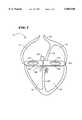
- FIG. 1is a simplified and diagrammatic sectional side view of the interior of the human heart
- FIG. 2is a front view of a multi-function element that can be used to both locate and ablate accessory pathways about annuli within the heart;
- FIG. 3is a top view of the element shown in FIG. 2;
- FIG. 4is a side view of the element shown in FIGS. 2 and 3;
- FIG. 5is a view of a system for mapping and ablating annuli of the heart using the element shown in FIGS. 2 to 4;
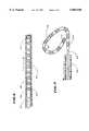
- FIG. 6is a side section view of a guide sheath used to introduce and deploy the element shown in FIG. 2 within the heart, with the element shown carried within the guide sheath;
- FIG. 7is a side section view of the guide sheath shown in FIG. 6, with the element shown deployed outside the guide sheath;
- FIG. 8is a diagrammatic view of the element shown in FIGS. 2 to 4 deployed on the annulus of the tricuspid valve in the right atrium;
- FIG. 9is a diagrammatic view of the element shown in FIGS. 2 to 4 deployed on the annulus of the mitral valve in the left atrium;
- FIG. 10is an enlarged view of the correspondence between the mapping display provided by the system shown in FIG. 5 and the electrodes carried by the element shown in FIGS. 2 to 4;
- FIG. 11is a diagrammatic view of a typical electrogram showing the time difference between the atrial complex and the ventricular complex;
- FIG. 12is an enlarged view of a display that embodies features of the invention and its correspondence between the electrodes carried by the element shown in FIGS. 2 to 4;
- FIG. 13is an enlarged view of a display that also embodies the features of the invention and that includes, in addition to a graphic display of sensed time difference, corresponding electrogram recordings;
- FIG. 14is an alternative embodiment of a probe that carries the element shown in FIGS. 2 to 4 and that shapes the element without using an outer guide sheath.
- FIG. 1shows a simplified and diagrammatic view of the interior structure of the human heart 10.
- FIG. 1The views of the heart 10 shown in FIG. 1 and other Figures in this Specification are not intended to be anatomically accurate in every detail.
- the Figuresshow views of the heart 10 in diagrammatic form as necessary to demonstrate the features of the invention.
- FIG. 1shows the right and left right atria, respectively 12 and 14.
- FIG. 1also shows the right and left ventricles, respectively 16 and 18.
- FIG. 1further shows the atrial septum 20 that separates the right and left atria 12/14.
- FIG. 1also shows the ventricular septum 22 that separates the right and left ventricles 16/18.
- FIG. 1also shows the fibrous structure of the AV groove 24 separating the atria 12/14 from the ventricles 16/18.
- the ring or annulus 26 of the tricuspid valve 28is formed in the AV groove 24 between the right atrium 12 and right ventricle 16.
- the ring or annulus 30 of the mitral (or bicuspid) valve 32is formed in the AV groove 24 between the left atrium and the left ventricle.
- the AV conduction systemincludes the sinoatrial node (or "SA node”) 34, which generates an electrical impulse to begin normal sinus rhythm.
- SA nodesinoatrial node
- the impulsepropagates uniformly across the right and left atria 12/14 and the atrial septum 20 to the atrioventricular (AV) groove 24, causing the atria 12/14 to contract.
- the AV conduction systemfurther includes the atrioventricular node (or "AV node”) 36 and the bundle of HIS (or “HIS bundle”) 38, through which the electrical impulse crosses over the AV groove 24 to the ventricles 16/18.
- AV nodeatrioventricular node
- HISor "HIS bundle”
- the AV node 36first slows the conduction of the impulse, allowing the atria 12/14 to completely contract.
- the HIS bundle 38then delivers the slowed impulse to the ventricles 16/18, causing them to contract.
- FIGS. 2 to 4show from various perspectives a multiple function element that locates and ablates accessory pathways about the valve annuli 26/30 on the AV groove 24.
- FIG. 2shows the element 40 from the top.
- FIG. 3shows the element 40 from the front.
- FIG. 4shows the element 40 from the side.
- the element 40comprises an elongated body 42 that is preformed into a generally curved or circular shape, resembling an open loop.
- the shapecorresponds to the circumferential geometry of a selected annulus 26/30.
- the body 42is preferably formed of an electrically nonconductive, biocompatible, resilient plastic material which retains its shape and does not soften significantly at human body temperature, like Pebax®, polyethylene, or Hytral®, (polyester).
- the geometry of the body 42can be created by thermoforming it into the desired shape.
- the body 42can include an interior core of super-elastic material, like Nitinol wire, which is itself preshaped into the desired configuration.
- This constructionprovides the body 42 with a modulus the lends both resilience and mechanical strength. As a consequence, the body 42 can be maneuvered by the physician into stable and uniform contact about the selected annulus 26/30.
- the preformed shape of the body 42is selected among a variety of curved geometries to overlie the anatomical geometry of the selected annulus. Since the tricuspid and mitral annuli 26/30 typically possess different geometries, so the invention can provide elements 40 possessing different corresponding shapes.
- the body 42carries an array of ring electrodes aligned side by side along the axis of the body 42. Ten electrodes are shown in FIGS. 2 to 4, designated E1 to E10. As FIGS. 2 to 4 show, the electrode array can also include an electrode E1 on the distal tip of the body 42.
- the ring electrodes E1 to E10can be made of a solid, electrically conducting material, like platinum or gold, attached about the body 42.
- the ring electrodes E1 to E10can be formed by coating the exterior surface of the body 42 with an electrically conducting material, like platinum or gold. The coating can be applied using sputtering, ion beam deposition, or equivalent techniques.
- the electrodes E1 to E10are electrically isolated one from the other.
- the electrodesare made from inflexible, metallic materials, they should not exceed 6 mm in length to preserve the overall flexibility of the element 40. If the electrodes are applied by coating, larger electrodes can be used. The spacing between adjacent electrodes should not be more than about twice the length of an individual electrode, so that the electrodes can serve two functions. First, they can uniformly apply ablating energy. Second, they can sense electrical events in heart tissue.
- each electrodeis 2 mm in length, they should not be spaced apart by more than 4 mm. Electrodes spaced apart by more than twice their individual length will not apply ablating energy uniformly about the entire annular area, unless the element 40 is periodically moved.
- the number of the ring electrodes E1 to E10 in the arraycan vary. In representative embodiments, the number of electrodes can range from about 6 to about 20. Of course, more or fewer electrodes could be used. The particular spacing between them can vary, depending upon the particular geometry of the region of use and the functionality desired, keeping in mind the minimum spacing requirements described above.
- the ring electrodes E1 to E10serve two functions. In one mode, the electrodes E1 to E10 serve as sensing or mapping electrodes to monitor the electrical activity in the AV groove about a selected annulus 26/30. In another mode, the electrodes E1 to E10 serve as ablation electrodes to emit energy to ablate tissue about the selected annulus 26/30.
- the element 40is part of an overall system 46 (see FIG. 5) that delivers, deploys, and operates the element 40 inside the heart.
- the system 46includes a probe 48.
- the probe 48has a guide tube 50 that carries the element 40 at its distal end.
- the probe 48also includes a handle or grip 52 attached to the proximal end of the guide tube 50.
- the guide tube 50carries a guide sheath 54, which slides fore and aft along the axis of the guide tube 50.
- FIG. 6shows, sliding the guide sheath 54 forward (that is, toward the element 40), progressive straightens out the resilient body 42, drawing it into the guide sheath 54.
- the body 42assumes the generally linear, low profile shape of the guide sheath (as FIG. 6 shows).
- the low profile shapeallows the physician to employ conventional percutaneous access techniques to introduce the element 40 into a selected region of the heart through a vein or artery.
- FIG. 7shows, sliding the guide sheath 54 to the rear (that is, away from the element 40), frees the body 42 from the confines of the sheath 54.
- the resilient memory of the body 42causes it to return to its preformed shape (as FIG. 7 shows).
- the system 46also includes a controller.
- Each ring electrode E1 to E10is electrically coupled to a signal wire (not shown) made of an electrically conductive material, like copper alloy.
- the signal wiresextend through the guide tube 50 into the handle 52.
- One or more connectors 58attach the proximal ends of the signal wires to an input plug on the controller 56.
- the controller 56includes a signal monitor module 60.
- the signal monitor module 60receives electrical signals detected by the ring electrodes E1 to E1.
- the signal monitor module 60processes the electrical signals to assist the physician in locating the site of accessory pathway relative to the selected annulus 26/30.
- the signal monitor moduledrives a display device 62 on the controller 56.
- the display device 62presents an analysis of electrical activity in a format that the physician can readily view and interpret.
- the controller 56also includes a generator module 64 that creates and transmits ablating energy to a selected one or more of the ring electrodes E1 to E10.
- the selected ring electrodes E1 to E10emit the energy to ablate myocardial tissue they are in contact with.
- the generator module 64transmits radiofrequency electromagnetic energy to the selected electrodes E1 to E10.
- the generator module 64can be operated (through the switch 66) to apply ablating energy to the ring electrodes E1 to E10 in either a unipolar mode or a bipolar mode (as FIG. 5 shows).
- the controlleralso includes a switch 68 for selecting either the signal monitor module 60 or the energy generator module 64, thereby choosing between operating the electrodes in a SENSING MODE and an ABLATING MODE (as FIG. 5 shows).
- the physicianuses a conventional introducer 70 (see FIG. 5) to establish access to a selected vein or artery.
- the physicianWith the guide sheath 54 moved forward and enclosing the element 40 (as FIG. 6 shows), the physician introduces the guide tube 50 and outer sheath 54 through a conventional hemostatic valve 72 on the introducer 70 (see FIG. 5). The physician progressively advances the guide tube 50 and guide sheath 54 through the access vein into the right atrium 12.
- the physicianobserves the progress of the guide sheath 54 using fluoroscopic or ultrasound imaging, or the like.
- the guide sheath 54can include a radio-opaque compound, such as barium, for this purpose.
- a radio-opaque markercan be placed at the distal end of the guide sheath 54.
- the guide sheath 54can itself be preshaped with a memory that assumes a prescribed curvature for simplifying access to the right or left atrium 12/14 through venous access.
- the probe 48can incorporate conventional catheter steering technology. This would provide the capability of remotely steering the element 40 during introduction into and use within the heart. once located in the desired atrium 12/14, the physician slides the guide sheath 54 back to free the element 40 (as FIG. 7 shows). The element 40 resiliently springs into its curved shape.
- the physiciancan use fluoroscopic or ultrasound imaging, or the like, to observe the element 40 while maneuvering it into contact with the selected annulus 26/30.
- the physiciancan deploy an angioscopic or ultrasonic viewing probe to aid positioning.
- FIG. 8shows the element 40 in contact with the annulus 26 of the tricuspid valve 28 in the right atrium 12.
- FIG. 9shows the element 40 in contact with the annulus 30 of the mitral valve 32 in the left atrium 14 after completion of a transeptal approach.
- the element 40is preferably placed in contact against the selected annulus 26/30 from the atrial side.
- the element 40could be placed in contact underneath (i.e., on the ventricular side) the associated valve, resting against the annulus 26/30 behind the chordae tendineae.
- the geometry required for a ventricular placementwill generally differ from that suited for an atrial-placement. The placement would depend upon the physician's choice and whether the insertion point of the accessory pathway is believed to lie on the atrial or ventricular side of the selected annulus 26/30.
- the physiciantakes steps to map the electrical events in the annulus 26/30.
- the physicianselects SENSING MODE. This activates the signal monitor module 60 and its associated display 62.
- the signal monitor module 60receives signals from the electrodes E1 to E10. These signals record electrical events in the cardiac cycle. The signal monitor module 60 analyses the signals and converts them to graphic images on the display 62.
- the signal monitor module 60can include a conventional microprocessor (e.g., using a 386/486 motherboard) to analyze and convert the signals.
- the nature and character of the graphic images on the display 62can vary.
- the displaypresents an array of graphic characters or icons, equal in number to the number of electrodes carried on the element.
- the graphic characterstake the shape of boxes (designated BOX1 to BOX10 in FIG. 10).
- the boxesare numbered to correspond to positions of bipolar pairs of the electrodes, as counted from the distal tip of the element 40.
- there are ten electrodes E1 to E10 on the elementso there are ten numbered boxes BOX1 to BOX10 presented on the display 62.
- a display 62can be presented on a conventional CRT screen. Alternatively, the display can presented on an LCD screen, or as a series of small lights or LCD's.
- the controller 56includes an input device 74 for entering commands (see FIG. 5).
- the input device 74is a conventional mouse, and the display 62 incorporates an interface that receives mouse-driven input.
- the display 62can integrate input and output by incorporating conventional touch screen technology.
- Other conventional input devicescan also be used, like a key board or a voice activated input.
- the individual boxes BOX1 to BOX10display graphic information that represents the time difference between the atrial and ventricular electrogram complexes sensed by the bipolar pairs of ring electrodes E1 to E10 about the selected annulus 26/30.
- BOX1displays the information associated with the complex recorded between electrodes E1 and E10.
- BOX2displays the information associated with the complex recorded between electrodes E1 and E2.
- BOX3displays the information associated with the complex recorded between electrodes E2 and E3.
- BOX4displays the information associated with the complex recorded between electrodes E3 and E4.
- BOX5displays the information associated with the complex recorded between electrodes E4 and E5.
- BOX6displays the information associated with the complex recorded between electrodes E5 and E6.
- BOX7displays the information associated with the complex recorded between electrodes E6 and E7.
- BOX8displays the information associated with the complex recorded between electrodes E7 and E8.
- BOX9displays the information associated with the complex recorded between electrodes E8 and E9.
- BOX10displays the information associated with the complex recorded between electrodes E9 and E10.
- FIG. 11shows the time difference in a typical electrogram as the time between the initiation of the atrial complex A (identified as T1) and the initiation of the ventricular complex V (identified as T2).
- the time difference (T2 - T1)is displayed either in absolute terms, as a number, or in symbolic terms, as colors within the boxes BOX1 to BOX10, or both.
- FIG. 12shows the element 40 in position on the atrial side of the tricuspid annulus 26, as well as the associated display 62.
- the location of an accessory pathwayis shown in FIG. 12 to appear on the annulus 26 at site AP.
- the sensed time difference between the atrial and ventricular complexes present by the display 62will be the smallest where the accessory pathway AP is located.
- Electrode E3lies closest to site AP.
- the time difference in BOX3(as measured between electrodes E2 and E3) to the smallest at 50 msec.
- the time differenceprogressively increases with distance from the accessory pathway AP up to a maximum time difference (150msec) at a location diametrically spaced across the annulus 26 from the accessory pathway AP (at BOX8, as measured between electrodes E7 and E8).
- the signal monitor module 60can also display a selected first color (C1) in the box (i.e., BOX3) corresponding to the smallest time difference.
- C1a selected first color
- the display 62progressively varies the colors or shades of color C2 to C6 in the other BOXES to correspond with the progressively increasing time differences.
- the sensing systemcan cause the smallest time difference to display the color red as C1.
- the subsequent colors C2 to C5sequentially fade using different colors (or different shades of the same color) from red to yellow and eventually to blue (as C6).
- the display 62shows the progression of the time differences along the accessory pathway. This helps the physician interpret the output with a glance.
- the display 62also includes the capability to display electrogram recordings 83 made by electrode pairs about the annulus 26, as selected by the physician based upon the time difference analysis.
- FIG. 13shows the selected pairs to be E1/E10; E2/E3; E4/E5; and E7/E8 (that is, BOX1; BOX3; BOX5; and BOX8).
- the electrogram signals 83(1); 83(3); 83(5); and 83(8)can also be displayed in the same colors according to the time difference color code, as FIG. 13 shows.
- the display 62can be used to confirm the results of the time difference analysis.
- the electrogram signal morphologycan be used by the physician to confirm the identity of the region of the accessory pathway AP.
- the electrogram signal 83(3)(selected as the site of the accessory pathway AP by the time difference analysis) also shows the shortest time between complexes), further indicating close proximity to the accessory pathway AP.
- Electrogram morphologyalso can be used by the physician to confirm uniform contact between the element 40 and the annulus 26.
- the electrogram morphologycan also be used to confirm the presence of an underlying valve structure (as would occur along the mitral valve annulus 30 close to the ventricular septum 22), where only low amplitude far-field signals are sensed.
- the physiciandoes not have to know the absolute location of the ring electrodes or insertion point of the accessory pathway itself. With the display 62, the physician knows that it is somewhere along the annulus. The invention allows the physician to proceed to ablate the insertion point without pinpointing its exact coordinates along the annulus.
- the display shown in FIG. 13suggests that the insertion point of the accessory pathway is somewhere in the region of electrode E3.
- the physiciantakes steps to ablate the insertion point.
- the physicianselects ABLATING MODE on the controller 56. This readies the energy generator module 64. The physician can then, upon additional commands, supply ablation energy to the element 40.
- the physicianselects one or more electrodes E1 to E10 on the element 40 for receiving ablating energy.
- the physicianWhen the input device 74 is mouse-driven, the physician operates the mouse to click-on the box or boxes BOX1 to BOX10 corresponding to electrodes E1 to E10 the physician wants to receive ablating energy.
- the input deviceis a touch screen, the physician touches the box or boxes on the screen corresponding to the electrode or electrodes the physician wants to receive ablating energy.
- the input deviceis a key board, the physician types in the electrode numbers.
- the input deviceis composed of multiple push buttons, the physician pushes the buttons corresponding to the selected electrodes or electrode pairs.
- the particular electrode selection and activation schemedepends upon whether the controller is operating in the unipolar or bipolar mode, as controlled by the switch 66.
- the physicianselects one or more electrodes in the region of the identified insertion point. Based upon the display shown in FIG. 12, the physician would have the option of selecting electrode E3 alone, or electrodes E3 and E4; or electrodes E2 and E3; or electrodes E2, E3, and E4.
- the energy generator module 64supplies power to the selected electrode or electrodes, based upon previously established ablation parameters (power, duration, etc., set by other switches 76 and 78 on the controller 56).
- the energy transmitted by the electrode(s)flows to an external indifferent electrode on the patient (not shown), which is typically an epidermal patch.
- the energycreates a region of thermally destroyed tissue (the lesion) where the tissue contacts the energized electrode(s).
- the physicianhas the option of selecting two or more adjacent electrodes in the region of the identified insertion point. For example, based upon the display in FIG. 12, the physician can select electrodes E2 and E3; or electrodes E2, E3, and E4; or electrodes E3 and E4.
- the energy generator module 64sets the polarity of selected electrodes to deliver a bipolar lesion between the designated electrodes.
- the elementIn the bipolar mode, the element can be operated with higher impedance, higher efficiencies, and more sensitivity to tissue contact than when operated in the unipolar mode.
- the physiciancan successively toggle between the SENSING MODE and the ABLATING MODE until the elimination of the accessory pathway has been confirmed.
- the element 40is carried at the distal end of a probe 80 which, unlike the probe 48 shown in FIG. 5, does not include a guide sheath 54 to control the shape of the element 40.
- the probe 80includes a conventional steering mechanism 82 with an external steering lever 84 for selectively bending or flexing the element 40 along its length, as the solid and phantom lines in FIG. 14 show.
- a representative steering mechanism 82 that can be usedis shown in Copending U.S. Application Ser. No. 07/789,260, now U.S. Pat. No. 5,365,861 which is incorporated by reference.
- FIG. 14shows in solid lines, forward movement of the steering lever 84 straightens the element 40. As FIG. 14 shows in phantom lines, rearward movement of the steering lever 84 flexes or curves the element 40 into its desired loop shape.
- Another alternative embodiment of the elementwould also not require a guide sheath 54.
- One alternative embodimentincludes the use of "shape memory” material that would change the shape of the element upon exposure to the temperature conditions present in the heart.
- Another alternative embodimentwould include an internal sliding stylet to shape the element, as disclosed in copending patent Application Ser. No. 08/099,843, filed Jul. 30, 1993, entitled “Variable Curve Electrophysiological Catheter,” now U.S. Pat. No. 5,397,321, and copending patent application Ser. No. 08/100,739 , filed Jul. 30, 1993, entitled “Variable Stiffness Electrophysiological Catheter,” now abandoned.
- the element itselfmay possess sufficient inherent flexible to permit its advancement through the vasculature with an outer sheath.
- the selected annulus 26/30can be mapped and ablating at one time, without the need to continuously reposition the element 40 and without the need to employ a separate ablation probe.
- the inventionresults in better tissue/electrode contact and stability, to minimize the occurrence of ineffective applications of ablating energy.
- the inventionthereby provides shorter and more effective procedures, with greater incidence of curative lesions.
Landscapes
- Health & Medical Sciences (AREA)
- Life Sciences & Earth Sciences (AREA)
- Heart & Thoracic Surgery (AREA)
- Engineering & Computer Science (AREA)
- Public Health (AREA)
- Animal Behavior & Ethology (AREA)
- Veterinary Medicine (AREA)
- Cardiology (AREA)
- General Health & Medical Sciences (AREA)
- Biomedical Technology (AREA)
- Surgery (AREA)
- Biophysics (AREA)
- Medical Informatics (AREA)
- Molecular Biology (AREA)
- Nuclear Medicine, Radiotherapy & Molecular Imaging (AREA)
- Physics & Mathematics (AREA)
- Radiology & Medical Imaging (AREA)
- Pathology (AREA)
- Physiology (AREA)
- Otolaryngology (AREA)
- Plasma & Fusion (AREA)
- Measurement And Recording Of Electrical Phenomena And Electrical Characteristics Of The Living Body (AREA)
- Surgical Instruments (AREA)
Abstract
Description
This application is a continuation of application Ser. No. 08/744,560, now U.S. Pat. No. 5,673,695 filed on Nov. 6, 1996, which is a continuation of application Ser. No. 08/632,920, now abandoned, filed Apr. 16, 1996, which is a continuation of Ser. No. 08/510,143 filed on Aug. 2, 1995, now abandoned which is a divisional of application Ser. No. 08/138,452 filed on Oct. 15, 1993, which is now abandoned.
The invention is directed to systems and methods for mapping and ablating the interior regions of the heart for treating cardiac conditions.
Normal sinus rhythm of the heart begins with the sinoatrial node (or "SA node" ) generating an electrical impulse. The impulse usually propagates uniformly across the right and left atria and the atrial septum to the atrioventricular (AV) groove. This propagation causes the atria to contract.
At the atrioventricular (AV) groove, the impulse encounters the so-called "skeleton" of the heart. Here, a fibrous structure separates the atria from the ventricles. The rings or annuli of the tricuspid valve (between the right atrium and right ventricle) and the mitral (or bicuspid) valve (between the left atrium and the left ventricle) are attached to this fibrous skeleton.
The fibrous skeleton is electrically inert. It normally acts as an insulator to block the conduction of the impulse from the SA node. The electrical impulse would be prevented from crossing over to the ventricular side of the AV groove, if not for the specialized AV conducting tissue, called the atrioventricular node (or "AV node") and the bundle of HIS (or "HIS bundle").
The AV node slows the conduction of the impulse to the ventricles, allowing the atria to first complete their contraction and empties blood from the atria into the ventricles. The slowed impulse eventually enters the HIS bundle, which delivers the impulse to the ventricular side. The ventricles then contract.
The AV conduction system results in the described, organized sequence of myocardial contraction.
Normally, the AV conduction system is the only way for electrical impulses to be conducted from the atria to the ventricles. However, some people are born with additional electrical conduction paths between the atria and ventricles. These extra connections are called "bypass tracts" or "accessory pathways". Accessory pathways consist of tiny bands of myocardial tissue that most commonly insert in atrial muscle on one end and ventricular muscle on the other end. The most common variety is located along the AV groove.
Accessory pathways offer a potential parallel route for electrical impulses, bypassing the normal AV conduction system.
The accessory pathways do not slow down the electrical impulse, like the AV node does. Instead, the accessory pathways conduct impulses more quickly, like myocardial tissue. When they conduct the impulses in the antegrade direction (i.e., from the atria to the ventricles), they precede the normal impulse from AV node, causing premature stimulation and contraction of the ventricles. When they conduct the impulses in the retrograde direction (i.e., from the ventricles to the atria), the atria contract after the ventricles do. In either case, normal heart rhythm becomes disrupted.
Patients with accessory pathways are susceptible to re-entrant tachycardias involving both the AV node and the accessory pathway. The resultant fast heart rate can be potentially life-threatening. The elevated heart rate can lead to serious hemodynamic compromise. Sudden syncope or hemodynamic collapse can occur.
Accessory pathways are generally invisible to the naked eye. They therefore must be located by their electrophysiologic effects.
Catheter-based techniques have been developed to record accessory pathway activation by mapping the left and right annuli of, respectively, the tricuspid valve and the mitral valve. The techniques map these regions within the heart using sensing electrodes carried by catheters introduced by vascular access into the heart.
These catheter-based techniques have allowed identification of the site of the accessory pathway. Once identified, the pathway can be rendered non-conductive by catheter-based ablation techniques.
However, physicians frequently find it difficult to map and ablate around these annuli, particularly when working on the atrial side. Many complex movements are presently required to map the entire annulus using conventional catheters. Stable and intimate contact between the myocardial tissue and the mapping electrodes are often difficult to achieve.
Furthermore, conventional systems require the use of separate ablating elements. Coordinating the position of the mapping electrodes and the ablating electrodes further compounds the difficulties.
As a result, mapping and ablating of accessory pathways using conventional catheter-based techniques are difficult and time consuming. For these reasons, many attempts at creating curative lesions ultimately fail.
There is a need for catheter-based systems and methods that simplify the procedures for mapping and ablating accessory pathways.
The invention provides systems and methods for improving catheter-based ablations of accessory pathways.
One aspect of the invention provides a multi-purpose array of electrodes for both sensing electrical events about a selected annulus region of the heart as well as for ablating tissue in the selected region. The electrode array comprises a support body having a generally circular shape that conforms to the circumferential geometry of the selected annulus region. An array of electrodes is positioned in a spaced apart pattern along the support body. Signal wires electrically coupled to the electrodes for conveying, in a first mode of operation signals representing electrical events sensed by the electrodes in the selected annulus region and for conveying, in a second mode of operation, energy to ablate tissue in the selected annulus region.
According to this aspect of the invention, the pattern spaces adjacent electrodes in the array no further apart than twice the length of the largest one of the adjacent electrodes. This spacing provides the capability to apply ablating energy uniformly about the entire selected annulus region without periodic movement of the electrode array. At the same time, the electrode spacing permits use of the same electrodes to sense electrical events in the selected annular region.
The electrode array that embodies this aspect of the invention reduces the time and complexity of a sensing and ablating procedure in the selected annulus region. The electrode array requires less manipulation, while providing better tissue/electrode contact and stability than conventional approaches.
In a preferred embodiment, the electrodes in the array comprise ring electrodes made of electrically conducting material. In one arrangement, the electrically conducting material comprises a metallic element fastened to the support body. In another arrangement, the electrically conducting material comprises a coating applied upon the support body.
Another aspect of the invention provides a system for sensing electrical events about a selected annulus region of the heart and for ablating tissue in the selected region. The system comprises a catheter having a guide body that carries the above described electrode array on its distal end. The signal wires electrically coupled to the electrodes are themselves electrically coupled to a controller.
According to this aspect of the invention, the controller is operative in two modes. In the first mode of operation, the controller conveys signals representing electrical events sensed by the electrodes in the selected annulus region. In the second mode of operation, the controller conveys energy to the electrodes to ablate tissue in the selected annulus region.
The controller also includes a display device that is operative in the first mode for displaying graphic information that represents the time differences between the atrial and ventricular electrogram complexes sensed by bipolar pairs of the electrodes on the selected annulus region.
According to this aspect of the invention, the display device shows the time differences sensed by the electrode array to progressively increase from a minimum amount up to a maximum amount, and then progressively decrease back to the minimum amount. The accessory pathway is located in the region of the electrode where the minimum time difference occurs. The display device thereby points the physician to the location of the accessory pathway.
In a preferred embodiment, the display device shows the time differences as either as alpha-numeric characters, or as colors that change according to the magnitude of the time differences, or both.
The invention provides precise positioning information with respect to an accessory pathway, without requiring the physician to know the absolute location of the array electrodes or of even the accessory pathway itself. According to the invention, the physician can proceed to ablate the accessory pathway without pinpointing its exact coordinates along the annulus.
In a preferred embodiment, the display device also shows electrogram signal morphologies for selected one or more of the bipolar electrode pairs. In this arrangement, each selected electrogram signal morphology is displayed in a color that changes according to the magnitude of the time difference associated with the selected electrogram signal morphology.
Another aspect of the invention provides a method for sensing electrical events about a selected annulus region of the heart. The method establishes a contact site between heart tissue along the selected annulus and an electrode array as generally described above. The method continuously maintains the site of contact between the electrode array and heart tissue while conveying signals representing electrical events sensed by bipolar pairs of electrodes in the selected annulus region. The method displays the signals as graphic information that represents the time differences between the atrial and ventricular electrogram complexes sensed by the bipolar pairs of the electrodes on the selected annulus region. The method selects the bipolar pair of electrodes that displays the least time separation between the atrial and ventricular complex. According to the invention, this electrode pair identifies the region of the accessory pathway.
In a preferred embodiment, the method includes the step of conveying energy to one or more of the electrodes of the selected bipolar pair to ablate tissue in the selected annulus region.
The various aspects of the invention provide systems and methods for locating and ablating accessory pathways about the annulus of either the tricuspid valve or the mitral valve. The ablation destroys the myocardial tissue in those regions where reentry circuits occur. The ablation interrupts electrical conduction in the accessory pathways, preventing tachycardia.
FIG. 1 is a simplified and diagrammatic sectional side view of the interior of the human heart;
FIG. 2 is a front view of a multi-function element that can be used to both locate and ablate accessory pathways about annuli within the heart;
FIG. 3 is a top view of the element shown in FIG. 2;
FIG. 4 is a side view of the element shown in FIGS. 2 and 3;
FIG. 5 is a view of a system for mapping and ablating annuli of the heart using the element shown in FIGS. 2 to 4;
FIG. 6 is a side section view of a guide sheath used to introduce and deploy the element shown in FIG. 2 within the heart, with the element shown carried within the guide sheath;
FIG. 7 is a side section view of the guide sheath shown in FIG. 6, with the element shown deployed outside the guide sheath;
FIG. 8 is a diagrammatic view of the element shown in FIGS. 2 to 4 deployed on the annulus of the tricuspid valve in the right atrium;
FIG. 9 is a diagrammatic view of the element shown in FIGS. 2 to 4 deployed on the annulus of the mitral valve in the left atrium;
FIG. 10 is an enlarged view of the correspondence between the mapping display provided by the system shown in FIG. 5 and the electrodes carried by the element shown in FIGS. 2 to 4;
FIG. 11 is a diagrammatic view of a typical electrogram showing the time difference between the atrial complex and the ventricular complex;
FIG. 12 is an enlarged view of a display that embodies features of the invention and its correspondence between the electrodes carried by the element shown in FIGS. 2 to 4;
FIG. 13 is an enlarged view of a display that also embodies the features of the invention and that includes, in addition to a graphic display of sensed time difference, corresponding electrogram recordings;
FIG. 14 is an alternative embodiment of a probe that carries the element shown in FIGS. 2 to 4 and that shapes the element without using an outer guide sheath.
The invention may be embodied in several forms without departing from its spirit or essential characteristics. The scope of the invention is defined in the appended claims, rather than in the specific description preceding them. All embodiments that fall within the meaning and range of equivalency of the claims are therefore intended to be embraced by the claims.
FIG. 1 shows a simplified and diagrammatic view of the interior structure of thehuman heart 10.
The views of theheart 10 shown in FIG. 1 and other Figures in this Specification are not intended to be anatomically accurate in every detail. The Figures show views of theheart 10 in diagrammatic form as necessary to demonstrate the features of the invention.
FIG. 1 shows the right and left right atria, respectively 12 and 14. FIG. 1 also shows the right and left ventricles, respectively 16 and 18.
FIG. 1 further shows theatrial septum 20 that separates the right and leftatria 12/14. FIG. 1 also shows theventricular septum 22 that separates the right andleft ventricles 16/18.
FIG. 1 also shows the fibrous structure of theAV groove 24 separating theatria 12/14 from theventricles 16/18. The ring orannulus 26 of thetricuspid valve 28 is formed in theAV groove 24 between theright atrium 12 andright ventricle 16. The ring orannulus 30 of the mitral (or bicuspid)valve 32 is formed in theAV groove 24 between the left atrium and the left ventricle.
The AV conduction system includes the sinoatrial node (or "SA node") 34, which generates an electrical impulse to begin normal sinus rhythm. In a normal heart, the impulse propagates uniformly across the right and leftatria 12/14 and theatrial septum 20 to the atrioventricular (AV)groove 24, causing theatria 12/14 to contract.
As theatria 12/14 contract, blood in theatria 12/14 enters theventricles 16/18 through the tricuspid andmitral valves
The AV conduction system further includes the atrioventricular node (or "AV node") 36 and the bundle of HIS (or "HIS bundle") 38, through which the electrical impulse crosses over theAV groove 24 to theventricles 16/18.
TheAV node 36 first slows the conduction of the impulse, allowing theatria 12/14 to completely contract. The HISbundle 38 then delivers the slowed impulse to theventricles 16/18, causing them to contract.
FIGS. 2 to 4 show from various perspectives a multiple function element that locates and ablates accessory pathways about thevalve annuli 26/30 on theAV groove 24. FIG. 2 shows theelement 40 from the top. FIG. 3 shows theelement 40 from the front. FIG. 4 shows theelement 40 from the side.
Theelement 40 comprises anelongated body 42 that is preformed into a generally curved or circular shape, resembling an open loop. The shape corresponds to the circumferential geometry of a selectedannulus 26/30.
Thebody 42 is preferably formed of an electrically nonconductive, biocompatible, resilient plastic material which retains its shape and does not soften significantly at human body temperature, like Pebax®, polyethylene, or Hytral®, (polyester).
The geometry of thebody 42 can be created by thermoforming it into the desired shape. Alternatively, thebody 42 can include an interior core of super-elastic material, like Nitinol wire, which is itself preshaped into the desired configuration.
This construction provides thebody 42 with a modulus the lends both resilience and mechanical strength. As a consequence, thebody 42 can be maneuvered by the physician into stable and uniform contact about the selectedannulus 26/30.
The preformed shape of thebody 42 is selected among a variety of curved geometries to overlie the anatomical geometry of the selected annulus. Since the tricuspid andmitral annuli 26/30 typically possess different geometries, so the invention can provideelements 40 possessing different corresponding shapes.
Regardless of its particular shape, thebody 42 carries an array of ring electrodes aligned side by side along the axis of thebody 42. Ten electrodes are shown in FIGS. 2 to 4, designated E1 to E10. As FIGS. 2 to 4 show, the electrode array can also include an electrode E1 on the distal tip of thebody 42.
The ring electrodes E1 to E10 can be made of a solid, electrically conducting material, like platinum or gold, attached about thebody 42. Alternatively, the ring electrodes E1 to E10 can be formed by coating the exterior surface of thebody 42 with an electrically conducting material, like platinum or gold. The coating can be applied using sputtering, ion beam deposition, or equivalent techniques.
The electrodes E1 to E10 are electrically isolated one from the other.
If the electrodes are made from inflexible, metallic materials, they should not exceed 6 mm in length to preserve the overall flexibility of theelement 40. If the electrodes are applied by coating, larger electrodes can be used. The spacing between adjacent electrodes should not be more than about twice the length of an individual electrode, so that the electrodes can serve two functions. First, they can uniformly apply ablating energy. Second, they can sense electrical events in heart tissue.
For example, if each electrode is 2 mm in length, they should not be spaced apart by more than 4 mm. Electrodes spaced apart by more than twice their individual length will not apply ablating energy uniformly about the entire annular area, unless theelement 40 is periodically moved.
The number of the ring electrodes E1 to E10 in the array can vary. In representative embodiments, the number of electrodes can range from about 6 to about 20. Of course, more or fewer electrodes could be used. The particular spacing between them can vary, depending upon the particular geometry of the region of use and the functionality desired, keeping in mind the minimum spacing requirements described above.
According to the invention, because of their close spacing, the ring electrodes E1 to E10 serve two functions. In one mode, the electrodes E1 to E10 serve as sensing or mapping electrodes to monitor the electrical activity in the AV groove about a selectedannulus 26/30. In another mode, the electrodes E1 to E10 serve as ablation electrodes to emit energy to ablate tissue about the selectedannulus 26/30.
According to the invention, theelement 40 is part of an overall system 46 (see FIG. 5) that delivers, deploys, and operates theelement 40 inside the heart.
As FIG. 5 shows, thesystem 46 includes aprobe 48. Theprobe 48 has aguide tube 50 that carries theelement 40 at its distal end. Theprobe 48 also includes a handle orgrip 52 attached to the proximal end of theguide tube 50. Theguide tube 50 carries aguide sheath 54, which slides fore and aft along the axis of theguide tube 50.
As FIG. 6 shows, sliding theguide sheath 54 forward (that is, toward the element 40), progressive straightens out theresilient body 42, drawing it into theguide sheath 54.
Confined within theguide sheath 54, thebody 42 assumes the generally linear, low profile shape of the guide sheath (as FIG. 6 shows). The low profile shape allows the physician to employ conventional percutaneous access techniques to introduce theelement 40 into a selected region of the heart through a vein or artery.
As FIG. 7 shows, sliding theguide sheath 54 to the rear (that is, away from the element 40), frees thebody 42 from the confines of thesheath 54. The resilient memory of thebody 42 causes it to return to its preformed shape (as FIG. 7 shows).
As FIG. 5 shows, thesystem 46 also includes a controller. Each ring electrode E1 to E10 is electrically coupled to a signal wire (not shown) made of an electrically conductive material, like copper alloy. The signal wires extend through theguide tube 50 into thehandle 52. One ormore connectors 58 attach the proximal ends of the signal wires to an input plug on thecontroller 56.
Thecontroller 56 includes asignal monitor module 60. Thesignal monitor module 60 receives electrical signals detected by the ring electrodes E1 to E1. Thesignal monitor module 60 processes the electrical signals to assist the physician in locating the site of accessory pathway relative to the selectedannulus 26/30.
In the illustrated and preferred embodiment (see FIG. 5), the signal monitor module drives adisplay device 62 on thecontroller 56. Thedisplay device 62 presents an analysis of electrical activity in a format that the physician can readily view and interpret.
Thecontroller 56 also includes agenerator module 64 that creates and transmits ablating energy to a selected one or more of the ring electrodes E1 to E10. The selected ring electrodes E1 to E10 emit the energy to ablate myocardial tissue they are in contact with.
While the particular type of ablating energy can vary, the illustrated embodiment, thegenerator module 64 transmits radiofrequency electromagnetic energy to the selected electrodes E1 to E10.
Preferably, thegenerator module 64 can be operated (through the switch 66) to apply ablating energy to the ring electrodes E1 to E10 in either a unipolar mode or a bipolar mode (as FIG. 5 shows).
The controller also includes aswitch 68 for selecting either thesignal monitor module 60 or theenergy generator module 64, thereby choosing between operating the electrodes in a SENSING MODE and an ABLATING MODE (as FIG. 5 shows).
To introduce and deploy theelement 40 within the heart, the physician uses a conventional introducer 70 (see FIG. 5) to establish access to a selected vein or artery.
With theguide sheath 54 moved forward and enclosing the element 40 (as FIG. 6 shows), the physician introduces theguide tube 50 andouter sheath 54 through a conventionalhemostatic valve 72 on the introducer 70 (see FIG. 5). The physician progressively advances theguide tube 50 and guidesheath 54 through the access vein into theright atrium 12.
The physician observes the progress of theguide sheath 54 using fluoroscopic or ultrasound imaging, or the like. Theguide sheath 54 can include a radio-opaque compound, such as barium, for this purpose. Alternatively, a radio-opaque marker can be placed at the distal end of theguide sheath 54.
Theguide sheath 54 can itself be preshaped with a memory that assumes a prescribed curvature for simplifying access to the right orleft atrium 12/14 through venous access.
In an alternative embodiment (not shown), theprobe 48 can incorporate conventional catheter steering technology. This would provide the capability of remotely steering theelement 40 during introduction into and use within the heart. once located in the desiredatrium 12/14, the physician slides theguide sheath 54 back to free the element 40 (as FIG. 7 shows). Theelement 40 resiliently springs into its curved shape.
The physician can use fluoroscopic or ultrasound imaging, or the like, to observe theelement 40 while maneuvering it into contact with the selectedannulus 26/30. Alternatively, the physician can deploy an angioscopic or ultrasonic viewing probe to aid positioning.
Using the invention, access to theannulus 26 of thetricuspid valve 28 can be accomplished through either the subclavian or jugular veins, without the need to remotely steer theelement 40. FIG. 8 shows theelement 40 in contact with theannulus 26 of thetricuspid valve 28 in theright atrium 12.
Using the invention, access to theannulus 30 of themitral valve 32 can also be accomplished through either the subclavian or jugular veins, employing a transeptal approach. Using this approach, the physician enters theleft atrium 14 from theright atrium 12 through theatrial septum 20. This approach is a well known and widely accepted technique used in other left atrium access procedures. FIG. 9 shows theelement 40 in contact with theannulus 30 of themitral valve 32 in theleft atrium 14 after completion of a transeptal approach.
As FIGS. 8 and 9 show, theelement 40 is preferably placed in contact against the selectedannulus 26/30 from the atrial side. Alternatively, theelement 40 could be placed in contact underneath (i.e., on the ventricular side) the associated valve, resting against theannulus 26/30 behind the chordae tendineae. The geometry required for a ventricular placement will generally differ from that suited for an atrial-placement. The placement would depend upon the physician's choice and whether the insertion point of the accessory pathway is believed to lie on the atrial or ventricular side of the selectedannulus 26/30.
Once the physician obtains good contact between the electrodes E1 to E10 and the selectedannulus 26/30, the physician takes steps to map the electrical events in theannulus 26/30.
Operating theswitch 68 on thecontroller 56, the physician selects SENSING MODE. This activates thesignal monitor module 60 and its associateddisplay 62.
Thesignal monitor module 60 receives signals from the electrodes E1 to E10. These signals record electrical events in the cardiac cycle. Thesignal monitor module 60 analyses the signals and converts them to graphic images on thedisplay 62. Thesignal monitor module 60 can include a conventional microprocessor (e.g., using a 386/486 motherboard) to analyze and convert the signals.
The nature and character of the graphic images on thedisplay 62 can vary. In the illustrated and preferred embodiment (as FIG. 10 shows), the display presents an array of graphic characters or icons, equal in number to the number of electrodes carried on the element.
In the illustrated display, the graphic characters take the shape of boxes (designated BOX1 to BOX10 in FIG. 10). The boxes are numbered to correspond to positions of bipolar pairs of the electrodes, as counted from the distal tip of theelement 40. In the illustrated embodiment, there are ten electrodes E1 to E10 on the element, so there are ten numbered boxes BOX1 to BOX10 presented on thedisplay 62. Adisplay 62 can be presented on a conventional CRT screen. Alternatively, the display can presented on an LCD screen, or as a series of small lights or LCD's.
Preferably, thecontroller 56 includes aninput device 74 for entering commands (see FIG. 5).
In the illustrated embodiment, theinput device 74 is a conventional mouse, and thedisplay 62 incorporates an interface that receives mouse-driven input. Alternatively, thedisplay 62 can integrate input and output by incorporating conventional touch screen technology. Other conventional input devices can also be used, like a key board or a voice activated input.
According to another aspect of the invention, the individual boxes BOX1 to BOX10 display graphic information that represents the time difference between the atrial and ventricular electrogram complexes sensed by the bipolar pairs of ring electrodes E1 to E10 about the selectedannulus 26/30.
As FIG. 10 shows, BOX1 displays the information associated with the complex recorded between electrodes E1 and E10. BOX2 displays the information associated with the complex recorded between electrodes E1 and E2. BOX3 displays the information associated with the complex recorded between electrodes E2 and E3. BOX4 displays the information associated with the complex recorded between electrodes E3 and E4. BOX5 displays the information associated with the complex recorded between electrodes E4 and E5. BOX6 displays the information associated with the complex recorded between electrodes E5 and E6. BOX7 displays the information associated with the complex recorded between electrodes E6 and E7. BOX8 displays the information associated with the complex recorded between electrodes E7 and E8. BOX9 displays the information associated with the complex recorded between electrodes E8 and E9. BOX10 displays the information associated with the complex recorded between electrodes E9 and E10.
FIG. 11 shows the time difference in a typical electrogram as the time between the initiation of the atrial complex A (identified as T1) and the initiation of the ventricular complex V (identified as T2). The time difference (T2 - T1) is displayed either in absolute terms, as a number, or in symbolic terms, as colors within the boxes BOX1 to BOX10, or both.
FIG. 12 shows theelement 40 in position on the atrial side of thetricuspid annulus 26, as well as the associateddisplay 62.
The location of an accessory pathway is shown in FIG. 12 to appear on theannulus 26 at site AP. According to the invention, the sensed time difference between the atrial and ventricular complexes present by thedisplay 62 will be the smallest where the accessory pathway AP is located.
Electrode E3 lies closest to site AP. As thedisplay 62 shows in FIG. 12, the time difference in BOX3 (as measured between electrodes E2 and E3) to the smallest at 50 msec. The time difference progressively increases with distance from the accessory pathway AP up to a maximum time difference (150msec) at a location diametrically spaced across theannulus 26 from the accessory pathway AP (at BOX8, as measured between electrodes E7 and E8).
Alternatively, or in addition to, thesignal monitor module 60 can also display a selected first color (C1) in the box (i.e., BOX3) corresponding to the smallest time difference. Thedisplay 62 progressively varies the colors or shades of color C2 to C6 in the other BOXES to correspond with the progressively increasing time differences.
For example, the sensing system can cause the smallest time difference to display the color red as C1. The subsequent colors C2 to C5 sequentially fade using different colors (or different shades of the same color) from red to yellow and eventually to blue (as C6).
In this way, thedisplay 62 shows the progression of the time differences along the accessory pathway. This helps the physician interpret the output with a glance.
In the illustrated and preferred embodiment (see FIG. 13), thedisplay 62 also includes the capability to displayelectrogram recordings 83 made by electrode pairs about theannulus 26, as selected by the physician based upon the time difference analysis. FIG. 13 shows the selected pairs to be E1/E10; E2/E3; E4/E5; and E7/E8 (that is, BOX1; BOX3; BOX5; and BOX8). The electrogram signals 83(1); 83(3); 83(5); and 83(8) can also be displayed in the same colors according to the time difference color code, as FIG. 13 shows.
By showing selected electrogram signal morphologies 83(1)/(3)/(5)/(8), thedisplay 62 can be used to confirm the results of the time difference analysis. The electrogram signal morphology can be used by the physician to confirm the identity of the region of the accessory pathway AP. For example, in FIG. 13, the electrogram signal 83(3) (selected as the site of the accessory pathway AP by the time difference analysis) also shows the shortest time between complexes), further indicating close proximity to the accessory pathway AP.
Electrogram morphology also can be used by the physician to confirm uniform contact between theelement 40 and theannulus 26. The electrogram morphology can also be used to confirm the presence of an underlying valve structure (as would occur along themitral valve annulus 30 close to the ventricular septum 22), where only low amplitude far-field signals are sensed.
With thedisplay 62, the physician does not have to know the absolute location of the ring electrodes or insertion point of the accessory pathway itself. With thedisplay 62, the physician knows that it is somewhere along the annulus. The invention allows the physician to proceed to ablate the insertion point without pinpointing its exact coordinates along the annulus.
The display shown in FIG. 13 suggests that the insertion point of the accessory pathway is somewhere in the region of electrode E3.
With this information, the physician takes steps to ablate the insertion point. Operating theswitch 68, the physician selects ABLATING MODE on thecontroller 56. This readies theenergy generator module 64. The physician can then, upon additional commands, supply ablation energy to theelement 40.
Using theinput device 74, the physician selects one or more electrodes E1 to E10 on theelement 40 for receiving ablating energy.
When theinput device 74 is mouse-driven, the physician operates the mouse to click-on the box or boxes BOX1 to BOX10 corresponding to electrodes E1 to E10 the physician wants to receive ablating energy. When the input device is a touch screen, the physician touches the box or boxes on the screen corresponding to the electrode or electrodes the physician wants to receive ablating energy. When the input device is a key board, the physician types in the electrode numbers. When the input device is composed of multiple push buttons, the physician pushes the buttons corresponding to the selected electrodes or electrode pairs.
The particular electrode selection and activation scheme depends upon whether the controller is operating in the unipolar or bipolar mode, as controlled by theswitch 66.
If the system is operating in a unipolar mode, the physician selects one or more electrodes in the region of the identified insertion point. Based upon the display shown in FIG. 12, the physician would have the option of selecting electrode E3 alone, or electrodes E3 and E4; or electrodes E2 and E3; or electrodes E2, E3, and E4.
Theenergy generator module 64 supplies power to the selected electrode or electrodes, based upon previously established ablation parameters (power, duration, etc., set byother switches
The energy transmitted by the electrode(s) flows to an external indifferent electrode on the patient (not shown), which is typically an epidermal patch. The energy creates a region of thermally destroyed tissue (the lesion) where the tissue contacts the energized electrode(s).
If thecontroller 56 is operating in a bipolar mode, the physician has the option of selecting two or more adjacent electrodes in the region of the identified insertion point. For example, based upon the display in FIG. 12, the physician can select electrodes E2 and E3; or electrodes E2, E3, and E4; or electrodes E3 and E4.
Theenergy generator module 64 sets the polarity of selected electrodes to deliver a bipolar lesion between the designated electrodes.
In the bipolar mode, the element can be operated with higher impedance, higher efficiencies, and more sensitivity to tissue contact than when operated in the unipolar mode.
Using theswitch 68, the physician can successively toggle between the SENSING MODE and the ABLATING MODE until the elimination of the accessory pathway has been confirmed.
The physician then slides theguide sheath 54 forward to enclose theelement 40. The physician then withdraws theguide tube 50 and guidesheath 54 from the heart, ending the procedure.
In an alternative embodiment (shown in FIG. 14), theelement 40 is carried at the distal end of a probe 80 which, unlike theprobe 48 shown in FIG. 5, does not include aguide sheath 54 to control the shape of theelement 40. Instead, the probe 80 includes aconventional steering mechanism 82 with anexternal steering lever 84 for selectively bending or flexing theelement 40 along its length, as the solid and phantom lines in FIG. 14 show.
Arepresentative steering mechanism 82 that can be used is shown in Copending U.S. Application Ser. No. 07/789,260, now U.S. Pat. No. 5,365,861 which is incorporated by reference.
As FIG. 14 shows in solid lines, forward movement of the steeringlever 84 straightens theelement 40. As FIG. 14 shows in phantom lines, rearward movement of the steeringlever 84 flexes or curves theelement 40 into its desired loop shape.
Other alternative embodiments of the element would also not require aguide sheath 54. One alternative embodiment (not shown) includes the use of "shape memory" material that would change the shape of the element upon exposure to the temperature conditions present in the heart. Another alternative embodiment would include an internal sliding stylet to shape the element, as disclosed in copending patent Application Ser. No. 08/099,843, filed Jul. 30, 1993, entitled "Variable Curve Electrophysiological Catheter," now U.S. Pat. No. 5,397,321, and copending patent application Ser. No. 08/100,739 , filed Jul. 30, 1993, entitled "Variable Stiffness Electrophysiological Catheter," now abandoned.
In still another alternative embodiment, the element itself may possess sufficient inherent flexible to permit its advancement through the vasculature with an outer sheath.
Nevertheless, use of the slidingguide sheath 54 to control the shape of the element 40 (as FIGS. 6 and 7 show) is still preferred, because it allows theelement 40 to inherently possess greater stiffness to generate greater contact forces about the selected annulus than the alternative embodiments would permit.
According to the invention, the selectedannulus 26/30 can be mapped and ablating at one time, without the need to continuously reposition theelement 40 and without the need to employ a separate ablation probe. The invention results in better tissue/electrode contact and stability, to minimize the occurrence of ineffective applications of ablating energy. The invention thereby provides shorter and more effective procedures, with greater incidence of curative lesions.
The features of the invention are set forth in the following claims.
Claims (6)
1. A system for sensing electrical events about a selected annulus region of the heart and for ablating tissue in the selected region comprising
a catheter comprising
a guide body having a distal end and a proximal end,
a handle carried on the proximal end of the guide body for manipulating the guide body,
an electrode array carried on the distal end of the guide body for sensing electrical events in heart tissue including
a support body having a generally circular shape that conforms to the circumferential geometry of the selected annulus region,
an array of electrodes positioned in a spaced apart pattern along the support body,
signal wires electrically coupled to the electrodes
a controller electrically coupled to the signal wires and being operative
(i) in a first mode of operation for conveying signals representing electrical events sensed by bipolar pairs of the electrodes in the selected annulus region, and
(ii) in a second mode of operation for conveying energy to one or more of the electrodes to ablate tissue in the selected annulus region, and
the controller further including means for switching between the first and second modes of operation and display means, operative in the first mode, for displaying graphic information that represents the time differences between the atrial and ventricular electrogram complexes sensed by the bipolar pairs of the electrodes on the selected annulus region.
2. A system according to claim 1
wherein the display means shows the time differences as alpha-numeric characters.
3. A system according to claim 1
wherein the display means shows the time differences as colors that change according to the magnitude of the time differences.
4. A system according to claim 1
wherein the display means shows electrogram signal morphologies for selected one or more of the bipolar electrode pairs.
5. A system according to claim 4
wherein each selected electrogram signal morphology is displayed in a color that changes according to the magnitude of the time difference associated with the selected electrogram signal morphology.
6. A system according to claim 1
wherein the pattern spaces adjacent electrodes in the array no further apart than twice the length of the largest one of the adjacent electrodes.
Priority Applications (1)
| Application Number | Priority Date | Filing Date | Title |
|---|---|---|---|
| US08/931,229US5860920A (en) | 1993-10-14 | 1997-09-16 | Systems for locating and ablating accessory pathways in the heart |
Applications Claiming Priority (5)
| Application Number | Priority Date | Filing Date | Title |
|---|---|---|---|
| US13845293A | 1993-10-14 | 1993-10-14 | |
| US51014395A | 1995-08-02 | 1995-08-02 | |
| US63292096A | 1996-04-16 | 1996-04-16 | |
| US08/744,560US5673695A (en) | 1995-08-02 | 1996-11-06 | Methods for locating and ablating accessory pathways in the heart |
| US08/931,229US5860920A (en) | 1993-10-14 | 1997-09-16 | Systems for locating and ablating accessory pathways in the heart |
Related Parent Applications (1)
| Application Number | Title | Priority Date | Filing Date |
|---|---|---|---|
| US08/744,560ContinuationUS5673695A (en) | 1993-10-14 | 1996-11-06 | Methods for locating and ablating accessory pathways in the heart |
Publications (1)
| Publication Number | Publication Date |
|---|---|
| US5860920Atrue US5860920A (en) | 1999-01-19 |
Family
ID=27056808
Family Applications (2)
| Application Number | Title | Priority Date | Filing Date |
|---|---|---|---|
| US08/744,560Expired - LifetimeUS5673695A (en) | 1993-10-14 | 1996-11-06 | Methods for locating and ablating accessory pathways in the heart |
| US08/931,229Expired - LifetimeUS5860920A (en) | 1993-10-14 | 1997-09-16 | Systems for locating and ablating accessory pathways in the heart |
Family Applications Before (1)
| Application Number | Title | Priority Date | Filing Date |
|---|---|---|---|
| US08/744,560Expired - LifetimeUS5673695A (en) | 1993-10-14 | 1996-11-06 | Methods for locating and ablating accessory pathways in the heart |
Country Status (1)
| Country | Link |
|---|---|
| US (2) | US5673695A (en) |
Cited By (113)
| Publication number | Priority date | Publication date | Assignee | Title |
|---|---|---|---|---|
| US6096036A (en)* | 1998-05-05 | 2000-08-01 | Cardiac Pacemakers, Inc. | Steerable catheter with preformed distal shape and method for use |
| US6146381A (en)* | 1998-05-05 | 2000-11-14 | Cardiac Pacemakers, Inc. | Catheter having distal region for deflecting axial forces |
| US6167291A (en)* | 1998-03-12 | 2000-12-26 | Cardima, Inc. | Protected pin connector for an electrophysiology catheter |
| US6315778B1 (en)* | 1999-09-10 | 2001-11-13 | C. R. Bard, Inc. | Apparatus for creating a continuous annular lesion |
| US6325797B1 (en)* | 1999-04-05 | 2001-12-04 | Medtronic, Inc. | Ablation catheter and method for isolating a pulmonary vein |
| US20020087151A1 (en)* | 2000-12-29 | 2002-07-04 | Afx, Inc. | Tissue ablation apparatus with a sliding ablation instrument and method |
| US20020128642A1 (en)* | 1998-10-23 | 2002-09-12 | Afx, Inc. | Directional microwave ablation instrument with marking device |
| US20020128647A1 (en)* | 1999-08-05 | 2002-09-12 | Ed Roschak | Devices for applying energy to tissue |
| WO2002089687A1 (en)* | 2001-05-03 | 2002-11-14 | Medtronic, Inc. | Ablation catheter assembly with radially decreasing helix and method of use |
| US20020193783A1 (en)* | 2000-01-18 | 2002-12-19 | Afx, Inc. | Microwave ablation instrument with flexible antenna assembly and method |
| US20030018358A1 (en)* | 1999-06-25 | 2003-01-23 | Vahid Saadat | Apparatus and methods for treating tissue |
| JP2003503103A (en)* | 1999-06-25 | 2003-01-28 | バヒド サーダット, | Apparatus and method for treating tissue |
| US6514249B1 (en) | 1997-07-08 | 2003-02-04 | Atrionix, Inc. | Positioning system and method for orienting an ablation element within a pulmonary vein ostium |
| US6564096B2 (en) | 2001-02-28 | 2003-05-13 | Robert A. Mest | Method and system for treatment of tachycardia and fibrillation |
| US20030105453A1 (en)* | 2001-05-03 | 2003-06-05 | Stewart Mark T. | Porous medical catheter and methods of manufacture |
| US6592581B2 (en)* | 1998-05-05 | 2003-07-15 | Cardiac Pacemakers, Inc. | Preformed steerable catheter with movable outer sleeve and method for use |
| US6595989B1 (en) | 1999-05-11 | 2003-07-22 | Atrionix, Inc. | Balloon anchor wire |
| US6616628B2 (en) | 2001-11-16 | 2003-09-09 | Cardiac Pacemakers, Inc. | Steerable catheter with a longitudinally adjustable curved core |
| US6619291B2 (en) | 2001-04-24 | 2003-09-16 | Edwin J. Hlavka | Method and apparatus for catheter-based annuloplasty |
| US6628976B1 (en) | 2000-01-27 | 2003-09-30 | Biosense Webster, Inc. | Catheter having mapping assembly |
| US20030191380A1 (en)* | 2000-01-27 | 2003-10-09 | Biosense Webster, Inc. | Method for mapping a tubular region near the heart |
| US20030195508A1 (en)* | 2002-02-28 | 2003-10-16 | Biosense Webster, Inc. | Catheter having circular ablation assembly |
| US20030220639A1 (en)* | 2002-02-19 | 2003-11-27 | Afx, Inc. | Apparatus and method for assessing transmuarlity of a tissue ablation |
| US6671533B2 (en) | 2001-10-11 | 2003-12-30 | Irvine Biomedical Inc. | System and method for mapping and ablating body tissue of the interior region of the heart |
| US6738674B2 (en) | 2001-07-25 | 2004-05-18 | Oscor Inc. | Implantable coronary sinus lead with mapping capabilities |
| US6746446B1 (en) | 2000-08-04 | 2004-06-08 | Cardima, Inc. | Electrophysiological device for the isthmus |
| US6758830B1 (en) | 1999-05-11 | 2004-07-06 | Atrionix, Inc. | Catheter positioning system |
| US20040138652A1 (en)* | 2000-04-12 | 2004-07-15 | Afx, Inc. | Electrode arrangement for use in a medical instrument |
| US20040172046A1 (en)* | 2002-10-21 | 2004-09-02 | Hlavka Edwin J. | Method and apparatus for performing catheter-based annuloplasty using local plications |
| US20040181137A1 (en)* | 2003-03-12 | 2004-09-16 | Rodriguez Cynthia D. | Catheter with contractable mapping assembly |
| US6795721B2 (en) | 2000-01-27 | 2004-09-21 | Biosense Webster, Inc. | Bidirectional catheter having mapping assembly |
| US20050004441A1 (en)* | 2001-10-11 | 2005-01-06 | Chen Peter C. | System and methods for locating and ablating arrhythomogenic tissues |
| US20050010095A1 (en)* | 1999-04-05 | 2005-01-13 | Medtronic, Inc. | Multi-purpose catheter apparatus and method of use |
| US20050033137A1 (en)* | 2002-10-25 | 2005-02-10 | The Regents Of The University Of Michigan | Ablation catheters and methods for their use |
| US6866662B2 (en) | 2002-07-23 | 2005-03-15 | Biosense Webster, Inc. | Ablation catheter having stabilizing array |
| US20050059448A1 (en)* | 2003-09-11 | 2005-03-17 | Scott Sims | Method and apparatus for playing card game |
| US20050056292A1 (en)* | 1999-08-05 | 2005-03-17 | Cooper Joel D. | Devices for maintaining patency of surgically created channels in tissue |
| US6869431B2 (en) | 1997-07-08 | 2005-03-22 | Atrionix, Inc. | Medical device with sensor cooperating with expandable member |
| US20050075629A1 (en)* | 2002-02-19 | 2005-04-07 | Afx, Inc. | Apparatus and method for assessing tissue ablation transmurality |
| US6892087B2 (en) | 2001-11-01 | 2005-05-10 | Oscor Inc. | Vascular introducer with mapping capabilities |
| US20050107783A1 (en)* | 1999-08-05 | 2005-05-19 | Broncus Technologies, Inc. | Devices for applying energy to tissue |
| US20050119734A1 (en)* | 2002-10-21 | 2005-06-02 | Spence Paul A. | Tissue fastening systems and methods utilizing magnetic guidance |
| US20050125011A1 (en)* | 2001-04-24 | 2005-06-09 | Spence Paul A. | Tissue fastening systems and methods utilizing magnetic guidance |
| US20050137700A1 (en)* | 2003-12-23 | 2005-06-23 | Spence Paul A. | Tissue fastening systems and methods utilizing magnetic guidance |
| US20050159788A1 (en)* | 2002-06-14 | 2005-07-21 | Kress David C. | Transmurality assessment apparatus and methods |
| US20050222563A1 (en)* | 2004-03-31 | 2005-10-06 | Mcdaniel Benjamin D | Catheter for circumferential ablation at or near a pulmonary vein |
| US20050251132A1 (en)* | 2002-10-25 | 2005-11-10 | Regents Of The University Of Michigan | Ablation catheters |
| WO2005115231A1 (en)* | 2004-05-17 | 2005-12-08 | C.R. Bard, Inc. | Electrophysiology system for mapping and ablating arrhythmias |
| US20060025765A1 (en)* | 2004-07-30 | 2006-02-02 | Jaime Landman | Electrosurgical systems and methods |
| US20060063121A1 (en)* | 2004-09-22 | 2006-03-23 | Barry David L | Containment apparatus for multi-pass ovens |
| US20060069429A1 (en)* | 2001-04-24 | 2006-03-30 | Spence Paul A | Tissue fastening systems and methods utilizing magnetic guidance |
| US7037334B1 (en) | 2001-04-24 | 2006-05-02 | Mitralign, Inc. | Method and apparatus for catheter-based annuloplasty using local plications |
| US20060106375A1 (en)* | 2004-11-15 | 2006-05-18 | Werneth Randell L | Ablation system with feedback |
| US20060111701A1 (en)* | 2004-11-24 | 2006-05-25 | Ablation Frontiers, Inc. | Atrial ablation catheter adapted for treatment of septal wall arrhythmogenic foci and method of use |
| US20060111700A1 (en)* | 2004-11-24 | 2006-05-25 | Ablation Frontiers, Inc. | Atrial ablation catheter and method of use |
| US20060116749A1 (en)* | 2003-07-18 | 2006-06-01 | Broncus Technologies, Inc. | Devices for maintaining patency of surgically created channels in tissue |
| US7099717B2 (en) | 2002-01-03 | 2006-08-29 | Afx Inc. | Catheter having improved steering |
| US20060206107A1 (en)* | 1999-05-28 | 2006-09-14 | Afx, Inc. | Monopole tip for ablation catheter and methods for using same |
| US20070010857A1 (en)* | 2005-07-05 | 2007-01-11 | Mitralign, Inc. | Tissue anchor, anchoring system and methods of using the same |
| US20070038056A1 (en)* | 2001-10-11 | 2007-02-15 | Carlo Pappone | System and methods for locating and ablating arrhythomogenic tissues |
| US20070038055A1 (en)* | 2000-01-27 | 2007-02-15 | Biosense Webster, Inc. | Catheter having mapping assembly |
| US20070051377A1 (en)* | 2003-11-12 | 2007-03-08 | Medtronic Vascular, Inc. | Cardiac valve annulus reduction system |
| US20070083195A1 (en)* | 2005-07-11 | 2007-04-12 | Werneth Randell L | Low power tissue ablation system |
| US20070083193A1 (en)* | 2005-08-22 | 2007-04-12 | Werneth Randell L | User interface for tissue ablation system |
| US20070118213A1 (en)* | 2005-11-23 | 2007-05-24 | Didier Loulmet | Methods, devices, and kits for treating mitral valve prolapse |
| US7226446B1 (en) | 1999-05-04 | 2007-06-05 | Dinesh Mody | Surgical microwave ablation assembly |
| US20070129760A1 (en)* | 2002-04-08 | 2007-06-07 | Ardian, Inc. | Methods and apparatus for intravasculary-induced neuromodulation or denervation |
| US20070299435A1 (en)* | 2006-06-23 | 2007-12-27 | Crowe John E | Apparatus and method for ablating tissue |
| US20080161705A1 (en)* | 2006-12-29 | 2008-07-03 | Podmore Jonathan L | Devices and methods for ablating near AV groove |
| US20080228266A1 (en)* | 2007-03-13 | 2008-09-18 | Mitralign, Inc. | Plication assistance devices and methods |
| US20080249518A1 (en)* | 2004-04-19 | 2008-10-09 | Prorhythm, Inc. | Ablation Devices with Sensor Structures |
| US20080281312A1 (en)* | 2007-05-11 | 2008-11-13 | Ablation Frontiers, Inc. | Ablation Therapy System and Method for Treating Continuous Atrial Fibrillation |
| US20090030411A1 (en)* | 2004-10-14 | 2009-01-29 | Werneth Randell L | Ablation catheter |
| EP2022397A1 (en) | 2007-08-08 | 2009-02-11 | ProRhythm, Inc. | Miniature circular mapping catheter |
| US20090043186A1 (en)* | 2007-08-08 | 2009-02-12 | Prorhythm, Inc. | Miniature circular mapping catheter |
| US20090043368A1 (en)* | 2007-08-08 | 2009-02-12 | Jung Eugene J | Miniature circular mapping catheter |
| US20090163794A1 (en)* | 2007-12-21 | 2009-06-25 | Masamitsu Muranushi | Devices and methods for cardiac mapping of an annular region |
| US20090287087A1 (en)* | 2006-11-22 | 2009-11-19 | Broncus Technologies, Inc. | Devices for creating passages and sensing for blood vessels |
| US20100010485A1 (en)* | 2008-07-10 | 2010-01-14 | Hs West Investments, Llc | Electrosurgical instrument with an ablation mode and a coagulation mode |
| US20100106153A1 (en)* | 2008-07-10 | 2010-04-29 | Hs West Investments, Llc | Electrosurgical instrument with an ablation mode and a coagulation mode |
| US20100152728A1 (en)* | 2008-12-11 | 2010-06-17 | Park Christopher J | Method and apparatus for determining the efficacy of a lesion |
| US20100222859A1 (en)* | 2008-12-30 | 2010-09-02 | Assaf Govari | Dual-purpose lasso catheter with irrigation using circumferentially arranged ring bump electrodes |
| KR101000320B1 (en) | 2008-04-15 | 2010-12-13 | (주) 태웅메디칼 | Bipolar electrode guide wire and catheter system using same |
| US7850685B2 (en) | 2005-06-20 | 2010-12-14 | Medtronic Ablation Frontiers Llc | Ablation catheter |
| US20110011917A1 (en)* | 2008-12-31 | 2011-01-20 | Hansen Medical, Inc. | Methods, devices, and kits for treating valve prolapse |
| US20110137298A1 (en)* | 2001-10-11 | 2011-06-09 | St. Jude Medical, Inc. | Ultrasound ablation apparatus with discrete staggered ablation zones |
| US20110146673A1 (en)* | 1999-08-05 | 2011-06-23 | Broncus Technologies, Inc. | Methods for treating chronic obstructive pulmonary disease |
| US20110146674A1 (en)* | 2004-07-19 | 2011-06-23 | Broncus Technologies, Inc. | Devices for delivering substances through an extra-anatomic opening created in an airway |
| US20110160724A1 (en)* | 2004-03-05 | 2011-06-30 | Hansen Medical, Inc. | System and method for denaturing and fixing collagenous tissue |
| US20110160719A1 (en)* | 2009-12-30 | 2011-06-30 | Assaf Govari | Catheter with arcuate end section |
| USRE42724E1 (en)* | 1999-06-03 | 2011-09-20 | C.R. Bard, Inc. | Method and apparatus for performing cardiac ablations |
| US8308682B2 (en) | 2003-07-18 | 2012-11-13 | Broncus Medical Inc. | Devices for maintaining patency of surgically created channels in tissue |
| US20130158545A1 (en)* | 2011-12-15 | 2013-06-20 | Assaf Govari | Monitoring and tracking bipolar ablation |
| US8475450B2 (en) | 2008-12-30 | 2013-07-02 | Biosense Webster, Inc. | Dual-purpose lasso catheter with irrigation |
| US8709034B2 (en) | 2011-05-13 | 2014-04-29 | Broncus Medical Inc. | Methods and devices for diagnosing, monitoring, or treating medical conditions through an opening through an airway wall |
| US8864822B2 (en) | 2003-12-23 | 2014-10-21 | Mitralign, Inc. | Devices and methods for introducing elements into tissue |
| US8888773B2 (en) | 2012-05-11 | 2014-11-18 | Medtronic Ardian Luxembourg S.A.R.L. | Multi-electrode catheter assemblies for renal neuromodulation and associated systems and methods |
| US8911461B2 (en) | 2007-03-13 | 2014-12-16 | Mitralign, Inc. | Suture cutter and method of cutting suture |
| US8920415B2 (en) | 2009-12-16 | 2014-12-30 | Biosense Webster (Israel) Ltd. | Catheter with helical electrode |
| US8934978B2 (en) | 2002-04-08 | 2015-01-13 | Medtronic Ardian Luxembourg S.A.R.L. | Methods and apparatus for renal neuromodulation |
| US8956352B2 (en) | 2010-10-25 | 2015-02-17 | Medtronic Ardian Luxembourg S.A.R.L. | Catheter apparatuses having multi-electrode arrays for renal neuromodulation and associated systems and methods |
| US9095321B2 (en) | 2012-11-21 | 2015-08-04 | Medtronic Ardian Luxembourg S.A.R.L. | Cryotherapeutic devices having integral multi-helical balloons and methods of making the same |
| US9179974B2 (en) | 2013-03-15 | 2015-11-10 | Medtronic Ardian Luxembourg S.A.R.L. | Helical push wire electrode |
| US9220433B2 (en) | 2011-06-30 | 2015-12-29 | Biosense Webster (Israel), Ltd. | Catheter with variable arcuate distal section |
| US9345532B2 (en) | 2011-05-13 | 2016-05-24 | Broncus Medical Inc. | Methods and devices for ablation of tissue |
| US9358112B2 (en) | 2001-04-24 | 2016-06-07 | Mitralign, Inc. | Method and apparatus for catheter-based annuloplasty using local plications |
| US9662169B2 (en) | 2011-07-30 | 2017-05-30 | Biosense Webster (Israel) Ltd. | Catheter with flow balancing valve |
| US9707035B2 (en) | 2002-04-08 | 2017-07-18 | Medtronic Ardian Luxembourg S.A.R.L. | Methods for catheter-based renal neuromodulation |
| US10272260B2 (en) | 2011-11-23 | 2019-04-30 | Broncus Medical Inc. | Methods and devices for diagnosing, monitoring, or treating medical conditions through an opening through an airway wall |
| US10736690B2 (en) | 2014-04-24 | 2020-08-11 | Medtronic Ardian Luxembourg S.A.R.L. | Neuromodulation catheters and associated systems and methods |
| US10918373B2 (en) | 2013-08-31 | 2021-02-16 | Edwards Lifesciences Corporation | Devices and methods for locating and implanting tissue anchors at mitral valve commissure |
| US11213678B2 (en) | 2013-09-09 | 2022-01-04 | Medtronic Ardian Luxembourg S.A.R.L. | Method of manufacturing a medical device for neuromodulation |
| US11660190B2 (en) | 2007-03-13 | 2023-05-30 | Edwards Lifesciences Corporation | Tissue anchors, systems and methods, and devices |
Families Citing this family (236)
| Publication number | Priority date | Publication date | Assignee | Title |
|---|---|---|---|---|
| US6413234B1 (en) | 1990-02-02 | 2002-07-02 | Ep Technologies, Inc. | Assemblies for creating compound curves in distal catheter regions |
| US5820591A (en)* | 1990-02-02 | 1998-10-13 | E. P. Technologies, Inc. | Assemblies for creating compound curves in distal catheter regions |
| US6183469B1 (en) | 1997-08-27 | 2001-02-06 | Arthrocare Corporation | Electrosurgical systems and methods for the removal of pacemaker leads |
| US5683366A (en)* | 1992-01-07 | 1997-11-04 | Arthrocare Corporation | System and method for electrosurgical tissue canalization |
| US6179824B1 (en) | 1993-05-10 | 2001-01-30 | Arthrocare Corporation | System and methods for electrosurgical restenosis of body lumens |
| US5699796A (en)* | 1993-01-29 | 1997-12-23 | Cardima, Inc. | High resolution intravascular signal detection |
| US6161543A (en) | 1993-02-22 | 2000-12-19 | Epicor, Inc. | Methods of epicardial ablation for creating a lesion around the pulmonary veins |
| US6915806B2 (en) | 1993-05-10 | 2005-07-12 | Arthrocare Corporation | Method for harvesting graft vessel |
| US5582609A (en)* | 1993-10-14 | 1996-12-10 | Ep Technologies, Inc. | Systems and methods for forming large lesions in body tissue using curvilinear electrode elements |
| CA2174129C (en)* | 1993-10-14 | 2004-03-09 | Sidney D. Fleischman | Electrode elements for forming lesion patterns |
| WO1995010320A1 (en) | 1993-10-15 | 1995-04-20 | Ep Technologies, Inc. | Device for lengthening cardiac conduction pathways |
| US6146379A (en)* | 1993-10-15 | 2000-11-14 | Ep Technologies, Inc. | Systems and methods for creating curvilinear lesions in body tissue |
| US6001093A (en) | 1993-10-15 | 1999-12-14 | Ep Technologies, Inc. | Systems and methods for creating long, thin lesions in body tissue |
| US5575810A (en)* | 1993-10-15 | 1996-11-19 | Ep Technologies, Inc. | Composite structures and methods for ablating tissue to form complex lesion patterns in the treatment of cardiac conditions and the like |
| US6245068B1 (en) | 1994-08-08 | 2001-06-12 | Scimed Life Systems, Inc. | Resilient radiopaque electrophysiology electrodes and probes including the same |
| US5885278A (en) | 1994-10-07 | 1999-03-23 | E.P. Technologies, Inc. | Structures for deploying movable electrode elements |
| US5897553A (en) | 1995-11-02 | 1999-04-27 | Medtronic, Inc. | Ball point fluid-assisted electrocautery device |
| US6409722B1 (en) | 1998-07-07 | 2002-06-25 | Medtronic, Inc. | Apparatus and method for creating, maintaining, and controlling a virtual electrode used for the ablation of tissue |
| AU5558096A (en)* | 1995-05-01 | 1996-11-21 | Medtronic Cardiorhythm | Dual curve ablation catheter and method |
| US6063077A (en)* | 1996-04-08 | 2000-05-16 | Cardima, Inc. | Linear ablation device and assembly |
| NL1003024C2 (en) | 1996-05-03 | 1997-11-06 | Tjong Hauw Sie | Stimulus conduction blocking instrument. |
| US6066139A (en)* | 1996-05-14 | 2000-05-23 | Sherwood Services Ag | Apparatus and method for sterilization and embolization |
| US7052493B2 (en) | 1996-10-22 | 2006-05-30 | Epicor Medical, Inc. | Methods and devices for ablation |
| US6805128B1 (en) | 1996-10-22 | 2004-10-19 | Epicor Medical, Inc. | Apparatus and method for ablating tissue |
| US6311692B1 (en) | 1996-10-22 | 2001-11-06 | Epicor, Inc. | Apparatus and method for diagnosis and therapy of electrophysiological disease |
| US6840936B2 (en) | 1996-10-22 | 2005-01-11 | Epicor Medical, Inc. | Methods and devices for ablation |
| US6719755B2 (en) | 1996-10-22 | 2004-04-13 | Epicor Medical, Inc. | Methods and devices for ablation |
| US6292700B1 (en) | 1999-09-10 | 2001-09-18 | Surx, Inc. | Endopelvic fascia treatment for incontinence |
| US6480746B1 (en) | 1997-08-13 | 2002-11-12 | Surx, Inc. | Noninvasive devices, methods, and systems for shrinking of tissues |
| US7317949B2 (en)* | 1996-11-08 | 2008-01-08 | Ams Research Corporation | Energy induced bulking and buttressing of tissues for incontinence |
| US6081749A (en)* | 1997-08-13 | 2000-06-27 | Surx, Inc. | Noninvasive devices, methods, and systems for shrinking of tissues |
| US5928224A (en)* | 1997-01-24 | 1999-07-27 | Hearten Medical, Inc. | Device for the treatment of damaged heart valve leaflets and methods of using the device |
| US6024740A (en) | 1997-07-08 | 2000-02-15 | The Regents Of The University Of California | Circumferential ablation device assembly |
| US5971983A (en) | 1997-05-09 | 1999-10-26 | The Regents Of The University Of California | Tissue ablation device and method of use |
| US6012457A (en) | 1997-07-08 | 2000-01-11 | The Regents Of The University Of California | Device and method for forming a circumferential conduction block in a pulmonary vein |
| JP3391466B2 (en) | 1997-06-13 | 2003-03-31 | アースロケア コーポレイション | Electrosurgical catheter system and catheter for recanalization of occluded body lumen |
| US6855143B2 (en) | 1997-06-13 | 2005-02-15 | Arthrocare Corporation | Electrosurgical systems and methods for recanalization of occluded body lumens |
| US5782900A (en)* | 1997-06-23 | 1998-07-21 | Irvine Biomedical, Inc. | Catheter system having safety means |
| US5888577A (en)* | 1997-06-30 | 1999-03-30 | Procath Corporation | Method for forming an electrophysiology catheter |
| US6652515B1 (en) | 1997-07-08 | 2003-11-25 | Atrionix, Inc. | Tissue ablation device assembly and method for electrically isolating a pulmonary vein ostium from an atrial wall |
| US6966908B2 (en) | 1997-07-08 | 2005-11-22 | Atrionix, Inc. | Tissue ablation device assembly and method for electrically isolating a pulmonary vein ostium from an atrial wall |
| US6245064B1 (en) | 1997-07-08 | 2001-06-12 | Atrionix, Inc. | Circumferential ablation device assembly |
| US6500174B1 (en) | 1997-07-08 | 2002-12-31 | Atrionix, Inc. | Circumferential ablation device assembly and methods of use and manufacture providing an ablative circumferential band along an expandable member |
| US6164283A (en)* | 1997-07-08 | 2000-12-26 | The Regents Of The University Of California | Device and method for forming a circumferential conduction block in a pulmonary vein |
| US6997925B2 (en) | 1997-07-08 | 2006-02-14 | Atrionx, Inc. | Tissue ablation device assembly and method for electrically isolating a pulmonary vein ostium from an atrial wall |
| US6096037A (en) | 1997-07-29 | 2000-08-01 | Medtronic, Inc. | Tissue sealing electrosurgery device and methods of sealing tissue |
| US9023031B2 (en) | 1997-08-13 | 2015-05-05 | Verathon Inc. | Noninvasive devices, methods, and systems for modifying tissues |
| JP2001514921A (en) | 1997-08-13 | 2001-09-18 | サークス, インコーポレイテッド | Non-invasive devices, methods, and systems for tissue contraction |
| US5897586A (en)* | 1997-08-15 | 1999-04-27 | Regents Of The University Of Minnesota | Implantable defibrillator lead |
| US8709007B2 (en) | 1997-10-15 | 2014-04-29 | St. Jude Medical, Atrial Fibrillation Division, Inc. | Devices and methods for ablating cardiac tissue |
| US6200315B1 (en)* | 1997-12-18 | 2001-03-13 | Medtronic, Inc. | Left atrium ablation catheter |
| US6047700A (en)* | 1998-03-30 | 2000-04-11 | Arthrocare Corporation | Systems and methods for electrosurgical removal of calcified deposits |
| US6527767B2 (en) | 1998-05-20 | 2003-03-04 | New England Medical Center | Cardiac ablation system and method for treatment of cardiac arrhythmias and transmyocardial revascularization |
| US6706039B2 (en) | 1998-07-07 | 2004-03-16 | Medtronic, Inc. | Method and apparatus for creating a bi-polar virtual electrode used for the ablation of tissue |
| US6537248B2 (en) | 1998-07-07 | 2003-03-25 | Medtronic, Inc. | Helical needle apparatus for creating a virtual electrode used for the ablation of tissue |
| US6623480B1 (en) | 1998-07-24 | 2003-09-23 | University Of Kentucky Research Foundation | Flexible recording/high energy electrode catheter with anchor for ablation of atrial flutter by radio frequency energy |
| US8308719B2 (en) | 1998-09-21 | 2012-11-13 | St. Jude Medical, Atrial Fibrillation Division, Inc. | Apparatus and method for ablating tissue |
| US6208881B1 (en) | 1998-10-20 | 2001-03-27 | Micropure Medical, Inc. | Catheter with thin film electrodes and method for making same |
| US6319250B1 (en)* | 1998-11-23 | 2001-11-20 | C.R. Bard, Inc | Tricuspid annular grasp catheter |
| CA2351323A1 (en)* | 1998-11-23 | 2000-06-08 | C.R. Bard, Inc. | Intracardiac grasp catheter |
| US6607502B1 (en) | 1998-11-25 | 2003-08-19 | Atrionix, Inc. | Apparatus and method incorporating an ultrasound transducer onto a delivery member |
| US6358273B1 (en) | 1999-04-09 | 2002-03-19 | Oratec Inventions, Inc. | Soft tissue heating apparatus with independent, cooperative heating sources |
| EP1207788A4 (en) | 1999-07-19 | 2009-12-09 | St Jude Medical Atrial Fibrill | Apparatus and method for ablating tissue |
| US6575966B2 (en)* | 1999-08-23 | 2003-06-10 | Cryocath Technologies Inc. | Endovascular cryotreatment catheter |
| US7706882B2 (en) | 2000-01-19 | 2010-04-27 | Medtronic, Inc. | Methods of using high intensity focused ultrasound to form an ablated tissue area |
| US8241274B2 (en) | 2000-01-19 | 2012-08-14 | Medtronic, Inc. | Method for guiding a medical device |
| US6595934B1 (en) | 2000-01-19 | 2003-07-22 | Medtronic Xomed, Inc. | Methods of skin rejuvenation using high intensity focused ultrasound to form an ablated tissue area containing a plurality of lesions |
| US6447443B1 (en) | 2001-01-13 | 2002-09-10 | Medtronic, Inc. | Method for organ positioning and stabilization |
| US8221402B2 (en) | 2000-01-19 | 2012-07-17 | Medtronic, Inc. | Method for guiding a medical device |
| US6402745B1 (en)* | 2000-02-23 | 2002-06-11 | Peter J. Wilk | Intravenous whip electrode for vein ablation |
| US8048070B2 (en) | 2000-03-06 | 2011-11-01 | Salient Surgical Technologies, Inc. | Fluid-assisted medical devices, systems and methods |
| DE60111517T2 (en) | 2000-04-27 | 2006-05-11 | Medtronic, Inc., Minneapolis | VIBRATION-SENSITIVE ABLATION DEVICE |
| US6488680B1 (en) | 2000-04-27 | 2002-12-03 | Medtronic, Inc. | Variable length electrodes for delivery of irrigated ablation |
| US6514250B1 (en) | 2000-04-27 | 2003-02-04 | Medtronic, Inc. | Suction stabilized epicardial ablation devices |
| ATE378009T1 (en) | 2000-05-16 | 2007-11-15 | Atrionix Inc | DEVICE WITH AN ULTRASONIC TRANSDUCER ON A FEEDER |
| ES2240470T3 (en) | 2000-06-13 | 2005-10-16 | Atrionix, Inc. | SURGICAL ABLATION PROBE THAT ALLOWS TO PERFORM A CIRCULAR INJURY. |
| US7306591B2 (en) | 2000-10-02 | 2007-12-11 | Novasys Medical, Inc. | Apparatus and methods for treating female urinary incontinence |
| US6926669B1 (en) | 2000-10-10 | 2005-08-09 | Medtronic, Inc. | Heart wall ablation/mapping catheter and method |
| US6475179B1 (en) | 2000-11-10 | 2002-11-05 | New England Medical Center | Tissue folding device for tissue ablation, and method thereof |
| US6728563B2 (en) | 2000-11-29 | 2004-04-27 | St. Jude Medical, Daig Division, Inc. | Electrophysiology/ablation catheter having “halo” configuration |
| US7081114B2 (en) | 2000-11-29 | 2006-07-25 | St. Jude Medical, Atrial Fibrillation Division, Inc. | Electrophysiology/ablation catheter having lariat configuration of variable radius |
| US7628780B2 (en) | 2001-01-13 | 2009-12-08 | Medtronic, Inc. | Devices and methods for interstitial injection of biologic agents into tissue |
| US20040138621A1 (en) | 2003-01-14 | 2004-07-15 | Jahns Scott E. | Devices and methods for interstitial injection of biologic agents into tissue |
| US7740623B2 (en) | 2001-01-13 | 2010-06-22 | Medtronic, Inc. | Devices and methods for interstitial injection of biologic agents into tissue |
| US6699240B2 (en) | 2001-04-26 | 2004-03-02 | Medtronic, Inc. | Method and apparatus for tissue ablation |
| US6663627B2 (en) | 2001-04-26 | 2003-12-16 | Medtronic, Inc. | Ablation system and method of use |
| US6648883B2 (en) | 2001-04-26 | 2003-11-18 | Medtronic, Inc. | Ablation system and method of use |
| US7959626B2 (en) | 2001-04-26 | 2011-06-14 | Medtronic, Inc. | Transmural ablation systems and methods |
| US6807968B2 (en) | 2001-04-26 | 2004-10-26 | Medtronic, Inc. | Method and system for treatment of atrial tachyarrhythmias |
| US7250048B2 (en) | 2001-04-26 | 2007-07-31 | Medtronic, Inc. | Ablation system and method of use |
| US6972016B2 (en)* | 2001-05-01 | 2005-12-06 | Cardima, Inc. | Helically shaped electrophysiology catheter |
| EP1435867B1 (en) | 2001-09-05 | 2010-11-17 | Salient Surgical Technologies, Inc. | Fluid-assisted medical devices and systems |
| US7753908B2 (en) | 2002-02-19 | 2010-07-13 | Endoscopic Technologies, Inc. (Estech) | Apparatus for securing an electrophysiology probe to a clamp |
| US7785324B2 (en) | 2005-02-25 | 2010-08-31 | Endoscopic Technologies, Inc. (Estech) | Clamp based lesion formation apparatus and methods configured to protect non-target tissue |
| US7674258B2 (en)* | 2002-09-24 | 2010-03-09 | Endoscopic Technologies, Inc. (ESTECH, Inc.) | Electrophysiology electrode having multiple power connections and electrophysiology devices including the same |
| US6656175B2 (en) | 2001-12-11 | 2003-12-02 | Medtronic, Inc. | Method and system for treatment of atrial tachyarrhythmias |
| US20040215310A1 (en)* | 2002-01-17 | 2004-10-28 | Omar Amirana | Stent and delivery method for applying RF energy to a pulmonary vein and the atrial wall around its ostium to eliminate atrial fibrillation while preventing stenosis of the pulmonary vein thereafter |
| US7967816B2 (en) | 2002-01-25 | 2011-06-28 | Medtronic, Inc. | Fluid-assisted electrosurgical instrument with shapeable electrode |
| US6827715B2 (en) | 2002-01-25 | 2004-12-07 | Medtronic, Inc. | System and method of performing an electrosurgical procedure |
| US7118566B2 (en) | 2002-05-16 | 2006-10-10 | Medtronic, Inc. | Device and method for needle-less interstitial injection of fluid for ablation of cardiac tissue |
| US7294143B2 (en) | 2002-05-16 | 2007-11-13 | Medtronic, Inc. | Device and method for ablation of cardiac tissue |
| US7083620B2 (en) | 2002-10-30 | 2006-08-01 | Medtronic, Inc. | Electrosurgical hemostat |
| US9597146B2 (en)* | 2003-01-21 | 2017-03-21 | Baylis Medical Company Inc. | Method of surgical perforation via the delivery of energy |
| US7048733B2 (en)* | 2003-09-19 | 2006-05-23 | Baylis Medical Company Inc. | Surgical perforation device with curve |
| US7947040B2 (en)* | 2003-01-21 | 2011-05-24 | Baylis Medical Company Inc | Method of surgical perforation via the delivery of energy |
| US7013169B2 (en)* | 2003-01-27 | 2006-03-14 | Cardiac Pacemakers, Inc. | Dual steer preshaped catheter |
| US7357800B2 (en)* | 2003-02-14 | 2008-04-15 | Boston Scientific Scimed, Inc. | Power supply and control apparatus and electrophysiology systems including the same |
| US7497857B2 (en) | 2003-04-29 | 2009-03-03 | Medtronic, Inc. | Endocardial dispersive electrode for use with a monopolar RF ablation pen |
| US7794454B2 (en)* | 2003-07-11 | 2010-09-14 | Medtronic Cryocath Lp | Method and device for epicardial ablation |
| US7438714B2 (en)* | 2003-09-12 | 2008-10-21 | Boston Scientific Scimed, Inc. | Vacuum-based catheter stabilizer |
| US20050059963A1 (en)* | 2003-09-12 | 2005-03-17 | Scimed Life Systems, Inc. | Systems and method for creating transmural lesions |
| US8052676B2 (en) | 2003-12-02 | 2011-11-08 | Boston Scientific Scimed, Inc. | Surgical methods and apparatus for stimulating tissue |
| US8002770B2 (en) | 2003-12-02 | 2011-08-23 | Endoscopic Technologies, Inc. (Estech) | Clamp based methods and apparatus for forming lesions in tissue and confirming whether a therapeutic lesion has been formed |
| US7608072B2 (en)* | 2003-12-02 | 2009-10-27 | Boston Scientific Scimed, Inc. | Surgical methods and apparatus for maintaining contact between tissue and electrophysiology elements and confirming whether a therapeutic lesion has been formed |
| US20050119653A1 (en)* | 2003-12-02 | 2005-06-02 | Swanson David K. | Surgical methods and apparatus for forming lesions in tissue and confirming whether a therapeutic lesion has been formed |
| US7371233B2 (en) | 2004-02-19 | 2008-05-13 | Boston Scientific Scimed, Inc. | Cooled probes and apparatus for maintaining contact between cooled probes and tissue |
| US8491636B2 (en) | 2004-03-23 | 2013-07-23 | Medtronic Cryopath LP | Method and apparatus for inflating and deflating balloon catheters |
| US9555223B2 (en) | 2004-03-23 | 2017-01-31 | Medtronic Cryocath Lp | Method and apparatus for inflating and deflating balloon catheters |
| US7727228B2 (en) | 2004-03-23 | 2010-06-01 | Medtronic Cryocath Lp | Method and apparatus for inflating and deflating balloon catheters |
| US7322973B2 (en)* | 2004-03-31 | 2008-01-29 | Cryocath Technologies Inc. | Method and apparatus for preventing atrial fibrillation |
| US8333764B2 (en) | 2004-05-12 | 2012-12-18 | Medtronic, Inc. | Device and method for determining tissue thickness and creating cardiac ablation lesions |
| JP2007537011A (en) | 2004-05-14 | 2007-12-20 | メドトロニック・インコーポレーテッド | Method and apparatus for treating atrial fibrillation by reducing mass |
| WO2005113057A1 (en)* | 2004-05-17 | 2005-12-01 | C. R. Bard, Inc. | Articulated catheter |
| US7122034B2 (en)* | 2004-05-27 | 2006-10-17 | St. Jude Medical, Atrial Fibrillation Division, Inc. | Curved ablation catheter |
| ATE516762T1 (en) | 2004-06-02 | 2011-08-15 | Medtronic Inc | ABLATION AND STAPLE INSTRUMENT |
| EP1750607A2 (en) | 2004-06-02 | 2007-02-14 | Medtronic, Inc. | Loop ablation apparatus and method |
| WO2005120374A1 (en) | 2004-06-02 | 2005-12-22 | Medtronic, Inc. | Compound bipolar ablation device and method |
| WO2005120376A2 (en) | 2004-06-02 | 2005-12-22 | Medtronic, Inc. | Ablation device with jaws |
| US8926635B2 (en)* | 2004-06-18 | 2015-01-06 | Medtronic, Inc. | Methods and devices for occlusion of an atrial appendage |
| US8663245B2 (en) | 2004-06-18 | 2014-03-04 | Medtronic, Inc. | Device for occlusion of a left atrial appendage |
| US8409219B2 (en) | 2004-06-18 | 2013-04-02 | Medtronic, Inc. | Method and system for placement of electrical lead inside heart |
| US7549988B2 (en) | 2004-08-30 | 2009-06-23 | Boston Scientific Scimed, Inc. | Hybrid lesion formation apparatus, systems and methods |
| US7727231B2 (en) | 2005-01-08 | 2010-06-01 | Boston Scientific Scimed, Inc. | Apparatus and methods for forming lesions in tissue and applying stimulation energy to tissue in which lesions are formed |
| EP1853188B1 (en)* | 2005-01-18 | 2020-03-11 | S.D.M.H. Pty. Ltd. | Device for thermal ablation of biological tissue using spherical ablation patterns |
| US7536225B2 (en) | 2005-01-21 | 2009-05-19 | Ams Research Corporation | Endo-pelvic fascia penetrating heating systems and methods for incontinence treatment |
| US7892228B2 (en)* | 2005-02-25 | 2011-02-22 | Boston Scientific Scimed, Inc. | Dual mode lesion formation apparatus, systems and methods |
| US7794455B2 (en)* | 2005-04-29 | 2010-09-14 | Medtronic Cryocath Lp | Wide area ablation of myocardial tissue |
| US7740627B2 (en)* | 2005-04-29 | 2010-06-22 | Medtronic Cryocath Lp | Surgical method and apparatus for treating atrial fibrillation |
| US8932208B2 (en) | 2005-05-26 | 2015-01-13 | Maquet Cardiovascular Llc | Apparatus and methods for performing minimally-invasive surgical procedures |
| US8016822B2 (en) | 2005-05-28 | 2011-09-13 | Boston Scientific Scimed, Inc. | Fluid injecting devices and methods and apparatus for maintaining contact between fluid injecting devices and tissue |
| WO2007092610A2 (en) | 2006-02-07 | 2007-08-16 | Tivamed, Inc. | Vaginal remodeling device and methods |
| US20080039746A1 (en) | 2006-05-25 | 2008-02-14 | Medtronic, Inc. | Methods of using high intensity focused ultrasound to form an ablated tissue area containing a plurality of lesions |
| US12161390B2 (en) | 2006-09-29 | 2024-12-10 | Boston Scientific Medical Device Limited | Connector system for electrosurgical device |
| US11666377B2 (en) | 2006-09-29 | 2023-06-06 | Boston Scientific Medical Device Limited | Electrosurgical device |
| ITBA20070049A1 (en)* | 2007-06-14 | 2008-12-15 | Massimo Grimaldi | CATHETERS FOR ABLATION TRANSCATETER BY PERCUTANEOUS ROUTE OF HEART ARITHMIA THROUGH BIPOLAR RADIOFREQUENCY |
| WO2009045265A1 (en) | 2007-10-05 | 2009-04-09 | Maquet Cardiovascular, Llc | Devices and methods for minimally-invasive surgical procedures |
| US8535308B2 (en) | 2007-10-08 | 2013-09-17 | Biosense Webster (Israel), Ltd. | High-sensitivity pressure-sensing probe |
| US8357152B2 (en) | 2007-10-08 | 2013-01-22 | Biosense Webster (Israel), Ltd. | Catheter with pressure sensing |
| US8882756B2 (en) | 2007-12-28 | 2014-11-11 | Medtronic Advanced Energy Llc | Fluid-assisted electrosurgical devices, methods and systems |
| US9833149B2 (en) | 2008-03-18 | 2017-12-05 | Circa Scientific, Llc | Methods, apparatus and systems for facilitating introduction of shaped medical instruments into the body of a subject |
| WO2009117523A2 (en) | 2008-03-18 | 2009-09-24 | Circa Medical, Llc | Large surface area temperature sensing device |
| EP2303171A2 (en) | 2008-05-13 | 2011-04-06 | Medtronic, Inc. | Tissue lesion evaluation |
| US8437832B2 (en) | 2008-06-06 | 2013-05-07 | Biosense Webster, Inc. | Catheter with bendable tip |
| US9101734B2 (en) | 2008-09-09 | 2015-08-11 | Biosense Webster, Inc. | Force-sensing catheter with bonded center strut |
| US9326700B2 (en) | 2008-12-23 | 2016-05-03 | Biosense Webster (Israel) Ltd. | Catheter display showing tip angle and pressure |
| US9254168B2 (en) | 2009-02-02 | 2016-02-09 | Medtronic Advanced Energy Llc | Electro-thermotherapy of tissue using penetrating microelectrode array |
| US8231620B2 (en)* | 2009-02-10 | 2012-07-31 | Tyco Healthcare Group Lp | Extension cutting blade |
| EP2398416B1 (en) | 2009-02-23 | 2015-10-28 | Medtronic Advanced Energy LLC | Fluid-assisted electrosurgical device |
| US9345541B2 (en) | 2009-09-08 | 2016-05-24 | Medtronic Advanced Energy Llc | Cartridge assembly for electrosurgical devices, electrosurgical unit and methods of use thereof |
| BR112012006059B8 (en)* | 2009-09-18 | 2021-06-22 | Viveve Inc | apparatus and system for remodeling a therapeutic zone in the tissue underlying a mucosal epithelium of female genital tissue |
| US10688278B2 (en) | 2009-11-30 | 2020-06-23 | Biosense Webster (Israel), Ltd. | Catheter with pressure measuring tip |
| US8521462B2 (en) | 2009-12-23 | 2013-08-27 | Biosense Webster (Israel), Ltd. | Calibration system for a pressure-sensitive catheter |
| US8529476B2 (en) | 2009-12-28 | 2013-09-10 | Biosense Webster (Israel), Ltd. | Catheter with strain gauge sensor |
| US8374670B2 (en) | 2010-01-22 | 2013-02-12 | Biosense Webster, Inc. | Catheter having a force sensing distal tip |
| EP2544616B1 (en) | 2010-03-11 | 2017-09-06 | Medtronic Advanced Energy LLC | Bipolar electrosurgical cutter with position insensitive return electrode contact |
| DE102010019648B4 (en)* | 2010-05-06 | 2019-07-11 | Acandis Gmbh | Electrode and method for producing such an electrode |
| US9744339B2 (en) | 2010-05-12 | 2017-08-29 | Circa Scientific, Llc | Apparatus for manually manipulating hollow organs |
| US20110295249A1 (en)* | 2010-05-28 | 2011-12-01 | Salient Surgical Technologies, Inc. | Fluid-Assisted Electrosurgical Devices, and Methods of Manufacture Thereof |
| US8798952B2 (en) | 2010-06-10 | 2014-08-05 | Biosense Webster (Israel) Ltd. | Weight-based calibration system for a pressure sensitive catheter |
| US9138289B2 (en) | 2010-06-28 | 2015-09-22 | Medtronic Advanced Energy Llc | Electrode sheath for electrosurgical device |
| US8920417B2 (en) | 2010-06-30 | 2014-12-30 | Medtronic Advanced Energy Llc | Electrosurgical devices and methods of use thereof |
| US8226580B2 (en) | 2010-06-30 | 2012-07-24 | Biosense Webster (Israel), Ltd. | Pressure sensing for a multi-arm catheter |
| US8906012B2 (en) | 2010-06-30 | 2014-12-09 | Medtronic Advanced Energy Llc | Electrosurgical devices with wire electrode |
| US8380276B2 (en) | 2010-08-16 | 2013-02-19 | Biosense Webster, Inc. | Catheter with thin film pressure sensing distal tip |
| US9289606B2 (en)* | 2010-09-02 | 2016-03-22 | St. Jude Medical, Atrial Fibrillation Division, Inc. | System for electroporation therapy |
| US8731859B2 (en) | 2010-10-07 | 2014-05-20 | Biosense Webster (Israel) Ltd. | Calibration system for a force-sensing catheter |
| US9023040B2 (en) | 2010-10-26 | 2015-05-05 | Medtronic Advanced Energy Llc | Electrosurgical cutting devices |
| US8979772B2 (en) | 2010-11-03 | 2015-03-17 | Biosense Webster (Israel), Ltd. | Zero-drift detection and correction in contact force measurements |
| US9427281B2 (en) | 2011-03-11 | 2016-08-30 | Medtronic Advanced Energy Llc | Bronchoscope-compatible catheter provided with electrosurgical device |
| US9387031B2 (en) | 2011-07-29 | 2016-07-12 | Medtronic Ablation Frontiers Llc | Mesh-overlayed ablation and mapping device |
| US9750565B2 (en) | 2011-09-30 | 2017-09-05 | Medtronic Advanced Energy Llc | Electrosurgical balloons |
| US8870864B2 (en) | 2011-10-28 | 2014-10-28 | Medtronic Advanced Energy Llc | Single instrument electrosurgery apparatus and its method of use |
| US9687289B2 (en) | 2012-01-04 | 2017-06-27 | Biosense Webster (Israel) Ltd. | Contact assessment based on phase measurement |
| US9168080B2 (en)* | 2012-01-27 | 2015-10-27 | Medtronic Cryocath Lp | Balloon catheter |
| EP4599879A2 (en) | 2012-05-31 | 2025-08-13 | Boston Scientific Medical Device Limited | Radiofrequency perforation apparatus |
| US9113911B2 (en) | 2012-09-06 | 2015-08-25 | Medtronic Ablation Frontiers Llc | Ablation device and method for electroporating tissue cells |
| US20140163652A1 (en)* | 2012-12-10 | 2014-06-12 | Thomas Witzel | Method for treating and repairing mitral valve annulus |
| EP2968846B1 (en) | 2013-03-12 | 2022-05-04 | Baylis Medical Company Inc. | Medical device having a support structure |
| US11937873B2 (en) | 2013-03-12 | 2024-03-26 | Boston Scientific Medical Device Limited | Electrosurgical device having a lumen |
| CA3220441A1 (en) | 2013-03-15 | 2015-09-17 | Boston Scientific Medical Device Limited | Electrosurgical device having a distal aperture |
| US9351783B2 (en) | 2013-05-01 | 2016-05-31 | Medtronic Cryocath Lp | Diagnostic guidewire for cryoablation sensing and pressure monitoring |
| WO2014179110A1 (en)* | 2013-05-03 | 2014-11-06 | St. Jude Medical, Cardiology Division, Inc. | Ablation system, methods, and controllers |
| CN105682726B (en) | 2013-08-07 | 2020-01-03 | 贝利斯医疗公司 | Method and apparatus for puncturing tissue |
| US10661057B2 (en) | 2013-12-20 | 2020-05-26 | Baylis Medical Company Inc. | Steerable medical device handle |
| US9974599B2 (en) | 2014-08-15 | 2018-05-22 | Medtronic Ps Medical, Inc. | Multipurpose electrosurgical device |
| WO2016088084A1 (en)* | 2014-12-03 | 2016-06-09 | Baylis Medical Company Inc. | Devices and methods for electrosurgical navigation |
| USD753302S1 (en) | 2015-02-11 | 2016-04-05 | Baylis Medical Company Inc. | Electrosurgical device with a curve |
| US11389227B2 (en) | 2015-08-20 | 2022-07-19 | Medtronic Advanced Energy Llc | Electrosurgical device with multivariate control |
| US11051875B2 (en) | 2015-08-24 | 2021-07-06 | Medtronic Advanced Energy Llc | Multipurpose electrosurgical device |
| AU2016319002B2 (en) | 2015-09-09 | 2021-05-13 | Boston Scientific Medical Device Limited | Epicardial access system & methods |
| US10716612B2 (en) | 2015-12-18 | 2020-07-21 | Medtronic Advanced Energy Llc | Electrosurgical device with multiple monopolar electrode assembly |
| WO2017118948A1 (en) | 2016-01-07 | 2017-07-13 | Baylis Medical Company Inc. | Hybrid transseptal dilator and methods of using the same |
| WO2018063798A1 (en)* | 2016-09-27 | 2018-04-05 | Cardiac Pacemakers, Inc. | Self stabilizing ablation suction catheter |
| CN110114027B (en) | 2016-11-01 | 2022-09-06 | 贝利斯医疗公司 | Method and apparatus for puncturing tissue |
| US11896823B2 (en) | 2017-04-04 | 2024-02-13 | Btl Healthcare Technologies A.S. | Method and device for pelvic floor tissue treatment |
| US10194975B1 (en) | 2017-07-11 | 2019-02-05 | Medtronic Advanced Energy, Llc | Illuminated and isolated electrosurgical apparatus |
| BR112020011128A2 (en) | 2017-08-10 | 2021-05-04 | Baylis Medical Company Inc. | heat exchange device and temperature sensor and method of use |
| US12023082B2 (en) | 2017-10-06 | 2024-07-02 | Medtronic Advanced Energy Llc | Hemostatic thermal sealer |
| EP3579909B1 (en) | 2017-12-05 | 2020-09-09 | Pedersen, Wesley Robert | Transseptal guide wire puncture system |
| CN112272574A (en) | 2018-05-08 | 2021-01-26 | 贝利斯医疗公司 | Coupling mechanism for device |
| AU2019204574A1 (en) | 2018-06-27 | 2020-01-23 | Viveve, Inc. | Methods for treating urinary stress incontinence |
| KR20220021468A (en) | 2019-04-29 | 2022-02-22 | 베이리스 메디컬 컴퍼니 아이엔씨. | Transseptal system, device and method |
| CN114126514A (en)* | 2019-07-09 | 2022-03-01 | Amx克立普管理有限责任公司 | Methods and devices for heart valve removal therapy |
| US11759190B2 (en) | 2019-10-18 | 2023-09-19 | Boston Scientific Medical Device Limited | Lock for medical devices, and related systems and methods |
| US11801087B2 (en) | 2019-11-13 | 2023-10-31 | Boston Scientific Medical Device Limited | Apparatus and methods for puncturing tissue |
| US11724070B2 (en) | 2019-12-19 | 2023-08-15 | Boston Scientific Medical Device Limited | Methods for determining a position of a first medical device with respect to a second medical device, and related systems and medical devices |
| USD1096819S1 (en) | 2019-12-23 | 2025-10-07 | Biosense Webster (Israel) Ltd. | Display screen with graphical user interface |
| US11006902B1 (en)* | 2019-12-23 | 2021-05-18 | Biosense Webster (Israel) Ltd. | GUI for selective operation of multi-electrode catheters |
| US11931098B2 (en) | 2020-02-19 | 2024-03-19 | Boston Scientific Medical Device Limited | System and method for carrying out a medical procedure |
| US12082792B2 (en) | 2020-02-25 | 2024-09-10 | Boston Scientific Medical Device Limited | Systems and methods for creating a puncture between aorta and the left atrium |
| US11986209B2 (en) | 2020-02-25 | 2024-05-21 | Boston Scientific Medical Device Limited | Methods and devices for creation of communication between aorta and left atrium |
| US11819243B2 (en) | 2020-03-19 | 2023-11-21 | Boston Scientific Medical Device Limited | Medical sheath and related systems and methods |
| US11826075B2 (en) | 2020-04-07 | 2023-11-28 | Boston Scientific Medical Device Limited | Elongated medical assembly |
| US12011279B2 (en) | 2020-04-07 | 2024-06-18 | Boston Scientific Medical Device Limited | Electro-anatomic mapping system |
| US12420067B2 (en) | 2020-05-12 | 2025-09-23 | Boston Scientific Medical Device Limited | Guidewire assembly |
| US11938285B2 (en) | 2020-06-17 | 2024-03-26 | Boston Scientific Medical Device Limited | Stop-movement device for elongated medical assembly |
| CN116437857A (en) | 2020-06-17 | 2023-07-14 | 波士顿科学医疗设备有限公司 | Electroanatomical mapping system |
| US11937796B2 (en) | 2020-06-18 | 2024-03-26 | Boston Scientific Medical Device Limited | Tissue-spreader assembly |
| US12343042B2 (en) | 2020-07-16 | 2025-07-01 | Boston Scientific Medical Device Limited | Pericardial puncture device and method |
| US12042178B2 (en) | 2020-07-21 | 2024-07-23 | Boston Scientific Medical Device Limited | System of medical devices and method for pericardial puncture |
| US12005202B2 (en) | 2020-08-07 | 2024-06-11 | Boston Scientific Medical Device Limited | Catheter having tissue-engaging device |
| US12396785B2 (en) | 2020-08-12 | 2025-08-26 | Boston Scientific Medical Device Limited | System of medical devices and method for pericardial puncture |
| CN111772784B (en)* | 2020-08-24 | 2025-02-14 | 龙德勇 | Ablation Device |
| CA3128527A1 (en) | 2020-09-10 | 2022-03-10 | Baylis Medical Company Inc. | Elongated medical catheter including marker band |
| US11980412B2 (en) | 2020-09-15 | 2024-05-14 | Boston Scientific Medical Device Limited | Elongated medical sheath |
| US12016656B2 (en) | 2020-10-09 | 2024-06-25 | QuantuMed Pty Ltd | Cellular ionic activity visualisation |
Citations (9)
| Publication number | Priority date | Publication date | Assignee | Title |
|---|---|---|---|---|
| US4776349A (en)* | 1985-10-04 | 1988-10-11 | Basem Nashef | Tubular device for the treatment of hollow organs with electric current |
| US4777955A (en)* | 1987-11-02 | 1988-10-18 | Cordis Corporation | Left ventricle mapping probe |
| US4940064A (en)* | 1986-11-14 | 1990-07-10 | Desai Jawahar M | Catheter for mapping and ablation and method therefor |
| US5228442A (en)* | 1991-02-15 | 1993-07-20 | Cardiac Pathways Corporation | Method for mapping, ablation, and stimulation using an endocardial catheter |
| US5263493A (en)* | 1992-02-24 | 1993-11-23 | Boaz Avitall | Deflectable loop electrode array mapping and ablation catheter for cardiac chambers |
| US5275162A (en)* | 1991-11-08 | 1994-01-04 | Ep Technologies, Inc. | Valve mapping catheter |
| US5354297A (en)* | 1992-02-14 | 1994-10-11 | Boaz Avitall | Biplanar deflectable catheter for arrhythmogenic tissue ablation |
| US5358479A (en)* | 1993-12-06 | 1994-10-25 | Electro-Catheter Corporation | Multiform twistable tip deflectable catheter |
| US5362926A (en)* | 1991-07-24 | 1994-11-08 | Denki Kagaku Kogyo Kabushiki Kaisha | Circuit substrate for mounting a semiconductor element |
Family Cites Families (1)
| Publication number | Priority date | Publication date | Assignee | Title |
|---|---|---|---|---|
| SU880410A1 (en)* | 1979-07-24 | 1981-11-15 | Ленинградский Научно-Исследовательский Институт По Болезням Уха, Горла, Носа И Речи | Electrode |
- 1996
- 1996-11-06USUS08/744,560patent/US5673695A/ennot_activeExpired - Lifetime
- 1997
- 1997-09-16USUS08/931,229patent/US5860920A/ennot_activeExpired - Lifetime
Patent Citations (9)
| Publication number | Priority date | Publication date | Assignee | Title |
|---|---|---|---|---|
| US4776349A (en)* | 1985-10-04 | 1988-10-11 | Basem Nashef | Tubular device for the treatment of hollow organs with electric current |
| US4940064A (en)* | 1986-11-14 | 1990-07-10 | Desai Jawahar M | Catheter for mapping and ablation and method therefor |
| US4777955A (en)* | 1987-11-02 | 1988-10-18 | Cordis Corporation | Left ventricle mapping probe |
| US5228442A (en)* | 1991-02-15 | 1993-07-20 | Cardiac Pathways Corporation | Method for mapping, ablation, and stimulation using an endocardial catheter |
| US5362926A (en)* | 1991-07-24 | 1994-11-08 | Denki Kagaku Kogyo Kabushiki Kaisha | Circuit substrate for mounting a semiconductor element |
| US5275162A (en)* | 1991-11-08 | 1994-01-04 | Ep Technologies, Inc. | Valve mapping catheter |
| US5354297A (en)* | 1992-02-14 | 1994-10-11 | Boaz Avitall | Biplanar deflectable catheter for arrhythmogenic tissue ablation |
| US5263493A (en)* | 1992-02-24 | 1993-11-23 | Boaz Avitall | Deflectable loop electrode array mapping and ablation catheter for cardiac chambers |
| US5358479A (en)* | 1993-12-06 | 1994-10-25 | Electro-Catheter Corporation | Multiform twistable tip deflectable catheter |
Non-Patent Citations (16)
| Title |
|---|
| Calkins et al., "Electrogram Criteria for the Identification of Appropriate Target Sites for Radiofrequency Catheter Ablation of Accessory Atrioventricular Connections," Circulation, vol. 85, No. 2, Feb. 1992, pp. 565-573. |
| Calkins et al., Electrogram Criteria for the Identification of Appropriate Target Sites for Radiofrequency Catheter Ablation of Accessory Atrioventricular Connections, Circulation , vol. 85, No. 2, Feb. 1992, pp. 565 573.* |
| Desai, et al., "Two-Phase Radiofrequency Catheter Ablation of Isolated Ventricular Endomyocardium," PACE, vol. 14, Jul., 1991, pp. 1179-1194. |
| Desai, et al., Two Phase Radiofrequency Catheter Ablation of Isolated Ventricular Endomyocardium, PACE , vol. 14, Jul., 1991, pp. 1179 1194.* |
| Gallagher et al., "Variants of Pre-excitation, Update 1989," Mechanisms of Clinical Arrhythmias, Part VIII, Chapter 53, pp. 480-490. |
| Gallagher et al., Variants of Pre excitation, Update 1989, Mechanisms of Clinical Arrhythmias , Part VIII, Chapter 53, pp. 480 490.* |
| Jackman et al., "Catheter Recordings of Accessory Atrioventricular Pathway Activation," Mechanisms of Clinical Arrhythmias, Part VII, Chapter 54, pp. 491-502. |
| Jackman et al., Catheter Recordings of Accessory Atrioventricular Pathway Activation, Mechanisms of Clinical Arrhythmias , Part VII, Chapter 54, pp. 491 502.* |
| Josephson et al., "Role of Catheter Mapping in the Preoperative Evaluation of Ventricular Tachycardia," The American Journal of Cardiology, vol. 49, Jan. 1982, pp. 207-220. |
| Josephson et al., Role of Catheter Mapping in the Preoperative Evaluation of Ventricular Tachycardia, The American Journal of Cardiology , vol. 49, Jan. 1982, pp. 207 220.* |
| Kuck, et al., "Sites of Conduction Block in Accessory Atrioventricular Pathways; Basis for Concealed Accessory Pathways," Mechanisms of Clinical Arrhythmias, Part VIII, Chapter 55, pp. 503-511. |
| Kuck, et al., Sites of Conduction Block in Accessory Atrioventricular Pathways; Basis for Concealed Accessory Pathways, Mechanisms of Clinical Arrhythmias , Part VIII, Chapter 55, pp. 503 511.* |
| Prystowski et al., "Pre-excited Tachycardias," Mechanisms of Clinical Arrhythmias, Part VII, Chapter 52, pp. 472-479. |
| Prystowski et al., Pre excited Tachycardias, Mechanisms of Clinical Arrhythmias , Part VII, Chapter 52, pp. 472 479.* |
| Yee, et al., "Tachycardia Associated with Accessory Atrioventricular Pathways," Mechanisms of Clinical Arrhythmias, Part VII, Chapter 51, pp. 463-472. |
| Yee, et al., Tachycardia Associated with Accessory Atrioventricular Pathways, Mechanisms of Clinical Arrhythmias , Part VII, Chapter 51, pp. 463 472.* |
Cited By (291)
| Publication number | Priority date | Publication date | Assignee | Title |
|---|---|---|---|---|
| US6514249B1 (en) | 1997-07-08 | 2003-02-04 | Atrionix, Inc. | Positioning system and method for orienting an ablation element within a pulmonary vein ostium |
| US6869431B2 (en) | 1997-07-08 | 2005-03-22 | Atrionix, Inc. | Medical device with sensor cooperating with expandable member |
| US6167291A (en)* | 1998-03-12 | 2000-12-26 | Cardima, Inc. | Protected pin connector for an electrophysiology catheter |
| US6146381A (en)* | 1998-05-05 | 2000-11-14 | Cardiac Pacemakers, Inc. | Catheter having distal region for deflecting axial forces |
| US6270496B1 (en)* | 1998-05-05 | 2001-08-07 | Cardiac Pacemakers, Inc. | Steerable catheter with preformed distal shape and method for use |
| US6096036A (en)* | 1998-05-05 | 2000-08-01 | Cardiac Pacemakers, Inc. | Steerable catheter with preformed distal shape and method for use |
| US6592581B2 (en)* | 1998-05-05 | 2003-07-15 | Cardiac Pacemakers, Inc. | Preformed steerable catheter with movable outer sleeve and method for use |
| US7052491B2 (en) | 1998-10-23 | 2006-05-30 | Afx, Inc. | Vacuum-assisted securing apparatus for a microwave ablation instrument |
| US20020128642A1 (en)* | 1998-10-23 | 2002-09-12 | Afx, Inc. | Directional microwave ablation instrument with marking device |
| US7115126B2 (en) | 1998-10-23 | 2006-10-03 | Afx Inc. | Directional microwave ablation instrument with off-set energy delivery portion |
| US7387627B2 (en) | 1998-10-23 | 2008-06-17 | Maquet Cardiovascular Llc | Vacuum-assisted securing apparatus for a microwave ablation instrument |
| US20030036754A1 (en)* | 1998-10-23 | 2003-02-20 | Lyndall Erb | Vacuum-assisted securing apparatus for a microwave ablation instrument |
| US20030195506A1 (en)* | 1999-04-05 | 2003-10-16 | Medtronic, Inc. | Ablation catheter and method for isolating a pulmonary vein |
| US20100204692A1 (en)* | 1999-04-05 | 2010-08-12 | Medtronic, Inc. | Ablation Catheter Assembly with Radially Decreasing Helix and Method of Use |
| US20050010095A1 (en)* | 1999-04-05 | 2005-01-13 | Medtronic, Inc. | Multi-purpose catheter apparatus and method of use |
| US6899711B2 (en)* | 1999-04-05 | 2005-05-31 | Medtronic, Inc. | Ablation catheter and method for isolating a pulmonary vein |
| US8257351B2 (en) | 1999-04-05 | 2012-09-04 | Medtronic, Inc. | Ablation catheter assembly with radially decreasing helix and method of use |
| US9554848B2 (en) | 1999-04-05 | 2017-01-31 | Medtronic, Inc. | Ablation catheters and associated systems and methods |
| US6325797B1 (en)* | 1999-04-05 | 2001-12-04 | Medtronic, Inc. | Ablation catheter and method for isolating a pulmonary vein |
| US6949097B2 (en)* | 1999-04-05 | 2005-09-27 | Medtronic, Inc. | Ablation catheter and method for isolating a pulmonary vein |
| US20040049181A1 (en)* | 1999-04-05 | 2004-03-11 | Medtronic, Inc. | Ablation catheter assembly with radially decreasing helix and method of use |
| US8834464B2 (en) | 1999-04-05 | 2014-09-16 | Mark T. Stewart | Ablation catheters and associated systems and methods |
| US20030195507A1 (en)* | 1999-04-05 | 2003-10-16 | Medtronic, Inc. | Ablation catheter and method for isolating a pulmonary vein |
| US6702811B2 (en) | 1999-04-05 | 2004-03-09 | Medtronic, Inc. | Ablation catheter assembly with radially decreasing helix and method of use |
| US6773433B2 (en)* | 1999-04-05 | 2004-08-10 | Medtronic, Inc. | Ablation catheter and method for isolating a pulmonary vein |
| US20030191463A1 (en)* | 1999-04-05 | 2003-10-09 | Medtronic, Inc. | Ablation catheter and method for isolating a pulmonary vein |
| US7771421B2 (en) | 1999-04-05 | 2010-08-10 | Medtronic, Inc. | Ablation catheter assembly with radially decreasing helix and method of use |
| US7226446B1 (en) | 1999-05-04 | 2007-06-05 | Dinesh Mody | Surgical microwave ablation assembly |
| US20040181188A1 (en)* | 1999-05-11 | 2004-09-16 | Schaer Alan K. | Catheter positioning system |
| US7731681B2 (en) | 1999-05-11 | 2010-06-08 | Atrionix, Inc. | Catheter positioning system |
| US6758830B1 (en) | 1999-05-11 | 2004-07-06 | Atrionix, Inc. | Catheter positioning system |
| US7881807B2 (en) | 1999-05-11 | 2011-02-01 | Schaer Alan K | Balloon anchor wire |
| US6595989B1 (en) | 1999-05-11 | 2003-07-22 | Atrionix, Inc. | Balloon anchor wire |
| US6811544B2 (en) | 1999-05-11 | 2004-11-02 | Alan K. Schaer | Catheter positioning system |
| US20060206107A1 (en)* | 1999-05-28 | 2006-09-14 | Afx, Inc. | Monopole tip for ablation catheter and methods for using same |
| US7346399B2 (en) | 1999-05-28 | 2008-03-18 | Afx, Inc. | Monopole tip for ablation catheter |
| USRE42724E1 (en)* | 1999-06-03 | 2011-09-20 | C.R. Bard, Inc. | Method and apparatus for performing cardiac ablations |
| JP2003503103A (en)* | 1999-06-25 | 2003-01-28 | バヒド サーダット, | Apparatus and method for treating tissue |
| US6669687B1 (en) | 1999-06-25 | 2003-12-30 | Vahid Saadat | Apparatus and methods for treating tissue |
| US20090264994A1 (en)* | 1999-06-25 | 2009-10-22 | Hansen Medical, Inc. | Apparatus and methods for treating tissue |
| US20030018358A1 (en)* | 1999-06-25 | 2003-01-23 | Vahid Saadat | Apparatus and methods for treating tissue |
| US8333204B2 (en) | 1999-06-25 | 2012-12-18 | Hansen Medical, Inc. | Apparatus and methods for treating tissue |
| US7217284B2 (en) | 1999-06-25 | 2007-05-15 | Houser Russell A | Apparatus and methods for treating tissue |
| US7186262B2 (en) | 1999-06-25 | 2007-03-06 | Vahid Saadat | Apparatus and methods for treating tissue |
| US8523883B2 (en) | 1999-06-25 | 2013-09-03 | Hansen Medical, Inc. | Apparatus and methods for treating tissue |
| US6626899B2 (en) | 1999-06-25 | 2003-09-30 | Nidus Medical, Llc | Apparatus and methods for treating tissue |
| US20100116279A9 (en)* | 1999-08-05 | 2010-05-13 | Cooper Joel D | Devices for maintaining patency of surgically created channels in tissue |
| US20020128647A1 (en)* | 1999-08-05 | 2002-09-12 | Ed Roschak | Devices for applying energy to tissue |
| US7815590B2 (en) | 1999-08-05 | 2010-10-19 | Broncus Technologies, Inc. | Devices for maintaining patency of surgically created channels in tissue |
| US20110146673A1 (en)* | 1999-08-05 | 2011-06-23 | Broncus Technologies, Inc. | Methods for treating chronic obstructive pulmonary disease |
| US20050056292A1 (en)* | 1999-08-05 | 2005-03-17 | Cooper Joel D. | Devices for maintaining patency of surgically created channels in tissue |
| US7422563B2 (en) | 1999-08-05 | 2008-09-09 | Broncus Technologies, Inc. | Multifunctional tip catheter for applying energy to tissue and detecting the presence of blood flow |
| US20050107783A1 (en)* | 1999-08-05 | 2005-05-19 | Broncus Technologies, Inc. | Devices for applying energy to tissue |
| US6315778B1 (en)* | 1999-09-10 | 2001-11-13 | C. R. Bard, Inc. | Apparatus for creating a continuous annular lesion |
| US20060116673A1 (en)* | 2000-01-18 | 2006-06-01 | Jules Gauthier | Ablation instrument and method |
| US7033352B1 (en) | 2000-01-18 | 2006-04-25 | Afx, Inc. | Flexible ablation instrument |
| US20020193783A1 (en)* | 2000-01-18 | 2002-12-19 | Afx, Inc. | Microwave ablation instrument with flexible antenna assembly and method |
| US7301131B2 (en) | 2000-01-18 | 2007-11-27 | Afx, Inc. | Microwave ablation instrument with flexible antenna assembly and method |
| US6804545B2 (en) | 2000-01-27 | 2004-10-12 | Biosense Webster, Inc. | Catheter having mapping assembly |
| US6711428B2 (en) | 2000-01-27 | 2004-03-23 | Biosense Webster, Inc. | Catheter having mapping assembly |
| US7187963B2 (en) | 2000-01-27 | 2007-03-06 | Biosense Webster, Inc. | Bidirectional catheter having mapping assembly |
| US7181262B2 (en) | 2000-01-27 | 2007-02-20 | Biosense Webster, Inc. | Method for mapping a tubular region near the heart |
| US20070038055A1 (en)* | 2000-01-27 | 2007-02-15 | Biosense Webster, Inc. | Catheter having mapping assembly |
| US20090259119A1 (en)* | 2000-01-27 | 2009-10-15 | Biosense Webster, Inc. | Catheter having mapping assembly |
| US6845257B2 (en) | 2000-01-27 | 2005-01-18 | Biosense Webster, Inc. | Method for mapping electrical activity |
| US7570982B2 (en) | 2000-01-27 | 2009-08-04 | Biosense Webster, Inc. | Catheter having mapping assembly |
| US20070179375A1 (en)* | 2000-01-27 | 2007-08-02 | Biosense Webster, Inc. | Method for mapping a tubular region near the heart |
| US8204571B2 (en) | 2000-01-27 | 2012-06-19 | Biosense Webster, Inc. | Catheter having mapping assembly |
| US7123951B2 (en) | 2000-01-27 | 2006-10-17 | Biosense Webster, Inc. | Catheter having mapping assembly |
| US20030199746A1 (en)* | 2000-01-27 | 2003-10-23 | Biosense Webster, Inc. | Catheter having mapping assembly |
| US20110166443A1 (en)* | 2000-01-27 | 2011-07-07 | Biosense Webster, Inc. | Catheter having mapping assembly |
| US20040158140A1 (en)* | 2000-01-27 | 2004-08-12 | Biosense Webster, Inc. | Catheter having mapping assembly |
| US7099711B2 (en) | 2000-01-27 | 2006-08-29 | Biosense Webster, Inc. | Method for mapping electrical activity |
| US6795721B2 (en) | 2000-01-27 | 2004-09-21 | Biosense Webster, Inc. | Bidirectional catheter having mapping assembly |
| US7917187B2 (en) | 2000-01-27 | 2011-03-29 | Biosense Webster, Inc. | Catheter having mapping assembly |
| US20040158139A1 (en)* | 2000-01-27 | 2004-08-12 | Fuimaono Kristine B. | Method for mapping electrical activity |
| US20030191380A1 (en)* | 2000-01-27 | 2003-10-09 | Biosense Webster, Inc. | Method for mapping a tubular region near the heart |
| US7610073B2 (en) | 2000-01-27 | 2009-10-27 | Biosense Webster, Inc. | Method for mapping a tubular region near the heart |
| US6628976B1 (en) | 2000-01-27 | 2003-09-30 | Biosense Webster, Inc. | Catheter having mapping assembly |
| US6987996B2 (en) | 2000-01-27 | 2006-01-17 | Biosense Webster, Inc. | Catheter having mapping assembly |
| US6976986B2 (en) | 2000-04-12 | 2005-12-20 | Afx, Inc. | Electrode arrangement for use in a medical instrument |
| US20050251129A1 (en)* | 2000-04-12 | 2005-11-10 | Dany Berube | Electrode arrangement for use in a medical instrument |
| US20040138652A1 (en)* | 2000-04-12 | 2004-07-15 | Afx, Inc. | Electrode arrangement for use in a medical instrument |
| US7156841B2 (en) | 2000-04-12 | 2007-01-02 | Afx, Inc. | Electrode arrangement for use in a medical instrument |
| US6746446B1 (en) | 2000-08-04 | 2004-06-08 | Cardima, Inc. | Electrophysiological device for the isthmus |
| US20030109868A1 (en)* | 2000-12-29 | 2003-06-12 | Afx, Inc. | Medical instrument positioning tool and method |
| US7303560B2 (en) | 2000-12-29 | 2007-12-04 | Afx, Inc. | Method of positioning a medical instrument |
| US20020087151A1 (en)* | 2000-12-29 | 2002-07-04 | Afx, Inc. | Tissue ablation apparatus with a sliding ablation instrument and method |
| US20030050631A1 (en)* | 2000-12-29 | 2003-03-13 | Afx, Inc. | Tissue ablation apparatus with a sliding ablation instrument and method |
| US6564096B2 (en) | 2001-02-28 | 2003-05-13 | Robert A. Mest | Method and system for treatment of tachycardia and fibrillation |
| US20050125011A1 (en)* | 2001-04-24 | 2005-06-09 | Spence Paul A. | Tissue fastening systems and methods utilizing magnetic guidance |
| US20060069429A1 (en)* | 2001-04-24 | 2006-03-30 | Spence Paul A | Tissue fastening systems and methods utilizing magnetic guidance |
| US6718985B2 (en) | 2001-04-24 | 2004-04-13 | Edwin J. Hlavka | Method and apparatus for catheter-based annuloplasty using local plications |
| US6619291B2 (en) | 2001-04-24 | 2003-09-16 | Edwin J. Hlavka | Method and apparatus for catheter-based annuloplasty |
| US7037334B1 (en) | 2001-04-24 | 2006-05-02 | Mitralign, Inc. | Method and apparatus for catheter-based annuloplasty using local plications |
| US20040019378A1 (en)* | 2001-04-24 | 2004-01-29 | Hlavka Edwin J. | Method and apparatus for performing catheter-based annuloplasty |
| US9358112B2 (en) | 2001-04-24 | 2016-06-07 | Mitralign, Inc. | Method and apparatus for catheter-based annuloplasty using local plications |
| WO2002089687A1 (en)* | 2001-05-03 | 2002-11-14 | Medtronic, Inc. | Ablation catheter assembly with radially decreasing helix and method of use |
| US20030105453A1 (en)* | 2001-05-03 | 2003-06-05 | Stewart Mark T. | Porous medical catheter and methods of manufacture |
| US7175734B2 (en) | 2001-05-03 | 2007-02-13 | Medtronic, Inc. | Porous medical catheter and methods of manufacture |
| US6738674B2 (en) | 2001-07-25 | 2004-05-18 | Oscor Inc. | Implantable coronary sinus lead with mapping capabilities |
| US20040138545A1 (en)* | 2001-10-11 | 2004-07-15 | Irvine Biomedical, Inc. | System and method for mapping and ablating body tissue of the interior region of the heart |
| US6671533B2 (en) | 2001-10-11 | 2003-12-30 | Irvine Biomedical Inc. | System and method for mapping and ablating body tissue of the interior region of the heart |
| US20070038056A1 (en)* | 2001-10-11 | 2007-02-15 | Carlo Pappone | System and methods for locating and ablating arrhythomogenic tissues |
| US20050004441A1 (en)* | 2001-10-11 | 2005-01-06 | Chen Peter C. | System and methods for locating and ablating arrhythomogenic tissues |
| US20110137298A1 (en)* | 2001-10-11 | 2011-06-09 | St. Jude Medical, Inc. | Ultrasound ablation apparatus with discrete staggered ablation zones |
| US8974446B2 (en) | 2001-10-11 | 2015-03-10 | St. Jude Medical, Inc. | Ultrasound ablation apparatus with discrete staggered ablation zones |
| US6892087B2 (en) | 2001-11-01 | 2005-05-10 | Oscor Inc. | Vascular introducer with mapping capabilities |
| US6616628B2 (en) | 2001-11-16 | 2003-09-09 | Cardiac Pacemakers, Inc. | Steerable catheter with a longitudinally adjustable curved core |
| US7099717B2 (en) | 2002-01-03 | 2006-08-29 | Afx Inc. | Catheter having improved steering |
| US7192427B2 (en) | 2002-02-19 | 2007-03-20 | Afx, Inc. | Apparatus and method for assessing transmurality of a tissue ablation |
| US20030220639A1 (en)* | 2002-02-19 | 2003-11-27 | Afx, Inc. | Apparatus and method for assessing transmuarlity of a tissue ablation |
| US20050075629A1 (en)* | 2002-02-19 | 2005-04-07 | Afx, Inc. | Apparatus and method for assessing tissue ablation transmurality |
| US6733499B2 (en) | 2002-02-28 | 2004-05-11 | Biosense Webster, Inc. | Catheter having circular ablation assembly |
| US20030195508A1 (en)* | 2002-02-28 | 2003-10-16 | Biosense Webster, Inc. | Catheter having circular ablation assembly |
| US8545495B2 (en) | 2002-02-28 | 2013-10-01 | Biosense Webster, Inc. | Catheter having circular ablation assembly |
| US7371232B2 (en) | 2002-02-28 | 2008-05-13 | Biosense Webster, Inc. | Catheter having circular ablation assembly |
| US9301801B2 (en) | 2002-02-28 | 2016-04-05 | Biosense Webster, Inc. | Catheter having circular ablation assembly |
| US7575566B2 (en) | 2002-02-28 | 2009-08-18 | Biosense Webster, Inc. | Catheter having circular ablation assembly |
| US20080281320A1 (en)* | 2002-02-28 | 2008-11-13 | Biosense Webster, Inc. | Catheter having circular ablation assembly |
| US9289255B2 (en) | 2002-04-08 | 2016-03-22 | Medtronic Ardian Luxembourg S.A.R.L. | Methods and apparatus for renal neuromodulation |
| US20070129760A1 (en)* | 2002-04-08 | 2007-06-07 | Ardian, Inc. | Methods and apparatus for intravasculary-induced neuromodulation or denervation |
| US9675413B2 (en) | 2002-04-08 | 2017-06-13 | Medtronic Ardian Luxembourg S.A.R.L. | Methods and apparatus for renal neuromodulation |
| US8934978B2 (en) | 2002-04-08 | 2015-01-13 | Medtronic Ardian Luxembourg S.A.R.L. | Methods and apparatus for renal neuromodulation |
| US8774913B2 (en) | 2002-04-08 | 2014-07-08 | Medtronic Ardian Luxembourg S.A.R.L. | Methods and apparatus for intravasculary-induced neuromodulation |
| US9707035B2 (en) | 2002-04-08 | 2017-07-18 | Medtronic Ardian Luxembourg S.A.R.L. | Methods for catheter-based renal neuromodulation |
| US20050159788A1 (en)* | 2002-06-14 | 2005-07-21 | Kress David C. | Transmurality assessment apparatus and methods |
| US20050113822A1 (en)* | 2002-07-23 | 2005-05-26 | Fuimaono Kristine B. | Ablation catheter having stabilizing array |
| US6866662B2 (en) | 2002-07-23 | 2005-03-15 | Biosense Webster, Inc. | Ablation catheter having stabilizing array |
| US7410486B2 (en) | 2002-07-23 | 2008-08-12 | Biosense Webster, Inc. | Ablation catheter having stabilizing array |
| US20050119734A1 (en)* | 2002-10-21 | 2005-06-02 | Spence Paul A. | Tissue fastening systems and methods utilizing magnetic guidance |
| US20050184122A1 (en)* | 2002-10-21 | 2005-08-25 | Mitralign, Inc. | Method and apparatus for performing catheter-based annuloplasty using local plications |
| US8979923B2 (en) | 2002-10-21 | 2015-03-17 | Mitralign, Inc. | Tissue fastening systems and methods utilizing magnetic guidance |
| US10028833B2 (en) | 2002-10-21 | 2018-07-24 | Mitralign, Inc. | Tissue fastening systems and methods utilizing magnetic guidance |
| US8460371B2 (en) | 2002-10-21 | 2013-06-11 | Mitralign, Inc. | Method and apparatus for performing catheter-based annuloplasty using local plications |
| US20050119735A1 (en)* | 2002-10-21 | 2005-06-02 | Spence Paul A. | Tissue fastening systems and methods utilizing magnetic guidance |
| US20040172046A1 (en)* | 2002-10-21 | 2004-09-02 | Hlavka Edwin J. | Method and apparatus for performing catheter-based annuloplasty using local plications |
| US20050251132A1 (en)* | 2002-10-25 | 2005-11-10 | Regents Of The University Of Michigan | Ablation catheters |
| US7857808B2 (en) | 2002-10-25 | 2010-12-28 | The Regents Of The University Of Michigan | Ablation catheters |
| US20070106293A1 (en)* | 2002-10-25 | 2007-05-10 | Hakan Oral | Ablation catheters |
| US20050033137A1 (en)* | 2002-10-25 | 2005-02-10 | The Regents Of The University Of Michigan | Ablation catheters and methods for their use |
| US7993333B2 (en) | 2002-10-25 | 2011-08-09 | The Regents Of The University Of Michigan | Ablation catheters |
| US20080161803A1 (en)* | 2002-10-25 | 2008-07-03 | The Regents Of The University Of Michigan | Ablation Catheters And Methods For Their Use |
| US7593760B2 (en) | 2003-03-12 | 2009-09-22 | Biosense Webster, Inc. | Catheter with contractable mapping assembly |
| US20040181137A1 (en)* | 2003-03-12 | 2004-09-16 | Rodriguez Cynthia D. | Catheter with contractable mapping assembly |
| US8000765B2 (en) | 2003-03-12 | 2011-08-16 | Biosense Webster, Inc. | Catheter with contractable mapping assembly |
| US8275440B2 (en) | 2003-03-12 | 2012-09-25 | Biosense Webster, Inc. | Catheter with contractable mapping assembly |
| US20110060207A1 (en)* | 2003-03-12 | 2011-03-10 | Biosense Webster, Inc. | Catheter with contractable mapping assembly |
| US7142903B2 (en) | 2003-03-12 | 2006-11-28 | Biosense Webster, Inc. | Catheter with contractable mapping assembly |
| US20060287592A1 (en)* | 2003-03-12 | 2006-12-21 | Rodriguez Cynthia D | Catheter with contractable mapping assembly |
| US7853302B2 (en) | 2003-03-12 | 2010-12-14 | Biosense Webster, Inc. | Catheter with contractable mapping assembly |
| US8308682B2 (en) | 2003-07-18 | 2012-11-13 | Broncus Medical Inc. | Devices for maintaining patency of surgically created channels in tissue |
| US20060116749A1 (en)* | 2003-07-18 | 2006-06-01 | Broncus Technologies, Inc. | Devices for maintaining patency of surgically created channels in tissue |
| US9533128B2 (en) | 2003-07-18 | 2017-01-03 | Broncus Medical Inc. | Devices for maintaining patency of surgically created channels in tissue |
| US8002740B2 (en) | 2003-07-18 | 2011-08-23 | Broncus Technologies, Inc. | Devices for maintaining patency of surgically created channels in tissue |
| US20050059448A1 (en)* | 2003-09-11 | 2005-03-17 | Scott Sims | Method and apparatus for playing card game |
| US20070051377A1 (en)* | 2003-11-12 | 2007-03-08 | Medtronic Vascular, Inc. | Cardiac valve annulus reduction system |
| US7655040B2 (en)* | 2003-11-12 | 2010-02-02 | Medtronic Vascular, Inc. | Cardiac valve annulus reduction system |
| US20080275503A1 (en)* | 2003-12-23 | 2008-11-06 | Mitralign, Inc. | Method of heart valve repair |
| US20070112424A1 (en)* | 2003-12-23 | 2007-05-17 | Mitralign, Inc. | Catheter based tissue fastening systems and methods |
| US8142493B2 (en) | 2003-12-23 | 2012-03-27 | Mitralign, Inc. | Method of heart valve repair |
| US7431726B2 (en) | 2003-12-23 | 2008-10-07 | Mitralign, Inc. | Tissue fastening systems and methods utilizing magnetic guidance |
| US20050137700A1 (en)* | 2003-12-23 | 2005-06-23 | Spence Paul A. | Tissue fastening systems and methods utilizing magnetic guidance |
| US8864822B2 (en) | 2003-12-23 | 2014-10-21 | Mitralign, Inc. | Devices and methods for introducing elements into tissue |
| US7166127B2 (en) | 2003-12-23 | 2007-01-23 | Mitralign, Inc. | Tissue fastening systems and methods utilizing magnetic guidance |
| US20050267571A1 (en)* | 2003-12-23 | 2005-12-01 | Spence Paul A | Tissue fastening systems and methods utilizing magnetic guidance |
| US20070080188A1 (en)* | 2003-12-23 | 2007-04-12 | Mitralign, Inc. | Tissue fastening systems and methods |
| US20110160724A1 (en)* | 2004-03-05 | 2011-06-30 | Hansen Medical, Inc. | System and method for denaturing and fixing collagenous tissue |
| US8926603B2 (en) | 2004-03-05 | 2015-01-06 | Hansen Medical, Inc. | System and method for denaturing and fixing collagenous tissue |
| US7976539B2 (en) | 2004-03-05 | 2011-07-12 | Hansen Medical, Inc. | System and method for denaturing and fixing collagenous tissue |
| US8007495B2 (en) | 2004-03-31 | 2011-08-30 | Biosense Webster, Inc. | Catheter for circumferential ablation at or near a pulmonary vein |
| US20050222563A1 (en)* | 2004-03-31 | 2005-10-06 | Mcdaniel Benjamin D | Catheter for circumferential ablation at or near a pulmonary vein |
| US8945120B2 (en) | 2004-03-31 | 2015-02-03 | Biosense Webster, Inc. | Catheter for circumferential ablation at or near a pulmonary vein |
| US8721633B2 (en) | 2004-04-19 | 2014-05-13 | Boston Scientific Scimed, Inc. | Ablation devices with sensors structures |
| US20080249518A1 (en)* | 2004-04-19 | 2008-10-09 | Prorhythm, Inc. | Ablation Devices with Sensor Structures |
| US9561043B2 (en) | 2004-04-19 | 2017-02-07 | Boston Scientific Scimed Inc. | Ablation devices with sensors structures |
| US8216216B2 (en) | 2004-04-19 | 2012-07-10 | Boston Scientific Scimed, Inc. | Ablation devices with sensor structures |
| US8398623B2 (en) | 2004-04-19 | 2013-03-19 | Boston Scientific Scimed, Inc. | Ablation devices with sensors structures |
| WO2005115231A1 (en)* | 2004-05-17 | 2005-12-08 | C.R. Bard, Inc. | Electrophysiology system for mapping and ablating arrhythmias |
| US20110146674A1 (en)* | 2004-07-19 | 2011-06-23 | Broncus Technologies, Inc. | Devices for delivering substances through an extra-anatomic opening created in an airway |
| US8608724B2 (en) | 2004-07-19 | 2013-12-17 | Broncus Medical Inc. | Devices for delivering substances through an extra-anatomic opening created in an airway |
| US8784400B2 (en) | 2004-07-19 | 2014-07-22 | Broncus Medical Inc. | Devices for delivering substances through an extra-anatomic opening created in an airway |
| US11357960B2 (en) | 2004-07-19 | 2022-06-14 | Broncus Medical Inc. | Devices for delivering substances through an extra-anatomic opening created in an airway |
| US10369339B2 (en) | 2004-07-19 | 2019-08-06 | Broncus Medical Inc. | Devices for delivering substances through an extra-anatomic opening created in an airway |
| US20060025765A1 (en)* | 2004-07-30 | 2006-02-02 | Jaime Landman | Electrosurgical systems and methods |
| WO2006015354A3 (en)* | 2004-07-30 | 2006-03-16 | Univ St Louis | Electrosurgical systems and methods |
| US20060063121A1 (en)* | 2004-09-22 | 2006-03-23 | Barry David L | Containment apparatus for multi-pass ovens |
| US9642675B2 (en) | 2004-10-14 | 2017-05-09 | Medtronic Ablation Frontiers Llc | Ablation catheter |
| US20090030411A1 (en)* | 2004-10-14 | 2009-01-29 | Werneth Randell L | Ablation catheter |
| US8486063B2 (en) | 2004-10-14 | 2013-07-16 | Medtronic Ablation Frontiers Llc | Ablation catheter |
| US20060106375A1 (en)* | 2004-11-15 | 2006-05-18 | Werneth Randell L | Ablation system with feedback |
| US8617152B2 (en) | 2004-11-15 | 2013-12-31 | Medtronic Ablation Frontiers Llc | Ablation system with feedback |
| US7468062B2 (en) | 2004-11-24 | 2008-12-23 | Ablation Frontiers, Inc. | Atrial ablation catheter adapted for treatment of septal wall arrhythmogenic foci and method of use |
| US20080306477A1 (en)* | 2004-11-24 | 2008-12-11 | Kunis Christopher G | Atrial ablation catheter and method of use |
| US8273084B2 (en) | 2004-11-24 | 2012-09-25 | Medtronic Ablation Frontiers Llc | Atrial ablation catheter and method of use |
| US7429261B2 (en) | 2004-11-24 | 2008-09-30 | Ablation Frontiers, Inc. | Atrial ablation catheter and method of use |
| US9005194B2 (en) | 2004-11-24 | 2015-04-14 | Medtronic Ablation Frontiers Llc | Atrial ablation catheter adapted for treatment of septal wall arrhythmogenic foci and method of use |
| US20060111701A1 (en)* | 2004-11-24 | 2006-05-25 | Ablation Frontiers, Inc. | Atrial ablation catheter adapted for treatment of septal wall arrhythmogenic foci and method of use |
| US20060111700A1 (en)* | 2004-11-24 | 2006-05-25 | Ablation Frontiers, Inc. | Atrial ablation catheter and method of use |
| US9468495B2 (en) | 2005-06-20 | 2016-10-18 | Medtronic Ablation Frontiers Llc | Ablation catheter |
| US7850685B2 (en) | 2005-06-20 | 2010-12-14 | Medtronic Ablation Frontiers Llc | Ablation catheter |
| US8979841B2 (en) | 2005-06-20 | 2015-03-17 | Medtronic Ablation Frontiers Llc | Ablation catheter |
| US20110106074A1 (en)* | 2005-06-20 | 2011-05-05 | Medtronic Ablation Frontiers Llc | Ablation catheter |
| US8771267B2 (en) | 2005-06-20 | 2014-07-08 | Medtronic Ablation Frontiers Llc | Ablation catheter |
| US8337492B2 (en) | 2005-06-20 | 2012-12-25 | Medtronic Ablation Frontiers Llc | Ablation catheter |
| US10695046B2 (en) | 2005-07-05 | 2020-06-30 | Edwards Lifesciences Corporation | Tissue anchor and anchoring system |
| US8951286B2 (en) | 2005-07-05 | 2015-02-10 | Mitralign, Inc. | Tissue anchor and anchoring system |
| US9814454B2 (en) | 2005-07-05 | 2017-11-14 | Mitralign, Inc. | Tissue anchor and anchoring system |
| US8951285B2 (en) | 2005-07-05 | 2015-02-10 | Mitralign, Inc. | Tissue anchor, anchoring system and methods of using the same |
| US20070010857A1 (en)* | 2005-07-05 | 2007-01-11 | Mitralign, Inc. | Tissue anchor, anchoring system and methods of using the same |
| US9259218B2 (en) | 2005-07-05 | 2016-02-16 | Mitralign, Inc. | Tissue anchor and anchoring system |
| US9566113B2 (en) | 2005-07-11 | 2017-02-14 | Medtronic Ablation Frontiers Llc | Low power tissue ablation system |
| US20070083195A1 (en)* | 2005-07-11 | 2007-04-12 | Werneth Randell L | Low power tissue ablation system |
| US8834461B2 (en) | 2005-07-11 | 2014-09-16 | Medtronic Ablation Frontiers Llc | Low power tissue ablation system |
| US8657814B2 (en) | 2005-08-22 | 2014-02-25 | Medtronic Ablation Frontiers Llc | User interface for tissue ablation system |
| US20070083193A1 (en)* | 2005-08-22 | 2007-04-12 | Werneth Randell L | User interface for tissue ablation system |
| US7632308B2 (en) | 2005-11-23 | 2009-12-15 | Didier Loulmet | Methods, devices, and kits for treating mitral valve prolapse |
| US8545551B2 (en) | 2005-11-23 | 2013-10-01 | Hansen Medical, Inc. | Methods, devices, and kits for treating mitral valve prolapse |
| US20100049311A1 (en)* | 2005-11-23 | 2010-02-25 | Didier Loulmet | Methods, devices, and kits for treating mitral valve prolapse |
| US20070118213A1 (en)* | 2005-11-23 | 2007-05-24 | Didier Loulmet | Methods, devices, and kits for treating mitral valve prolapse |
| US20070299435A1 (en)* | 2006-06-23 | 2007-12-27 | Crowe John E | Apparatus and method for ablating tissue |
| US9913969B2 (en) | 2006-10-05 | 2018-03-13 | Broncus Medical Inc. | Devices for delivering substances through an extra-anatomic opening created in an airway |
| US20090287087A1 (en)* | 2006-11-22 | 2009-11-19 | Broncus Technologies, Inc. | Devices for creating passages and sensing for blood vessels |
| US20080161705A1 (en)* | 2006-12-29 | 2008-07-03 | Podmore Jonathan L | Devices and methods for ablating near AV groove |
| WO2008083113A3 (en)* | 2006-12-29 | 2008-09-04 | St Jude Medical Atrial Fibrill | Devices and methods for ablating near av groove |
| US9358111B2 (en) | 2007-03-13 | 2016-06-07 | Mitralign, Inc. | Tissue anchors, systems and methods, and devices |
| US20080228266A1 (en)* | 2007-03-13 | 2008-09-18 | Mitralign, Inc. | Plication assistance devices and methods |
| US8911461B2 (en) | 2007-03-13 | 2014-12-16 | Mitralign, Inc. | Suture cutter and method of cutting suture |
| US9750608B2 (en) | 2007-03-13 | 2017-09-05 | Mitralign, Inc. | Systems and methods for introducing elements into tissue |
| US8845723B2 (en) | 2007-03-13 | 2014-09-30 | Mitralign, Inc. | Systems and methods for introducing elements into tissue |
| US11660190B2 (en) | 2007-03-13 | 2023-05-30 | Edwards Lifesciences Corporation | Tissue anchors, systems and methods, and devices |
| US20080281312A1 (en)* | 2007-05-11 | 2008-11-13 | Ablation Frontiers, Inc. | Ablation Therapy System and Method for Treating Continuous Atrial Fibrillation |
| US8641704B2 (en) | 2007-05-11 | 2014-02-04 | Medtronic Ablation Frontiers Llc | Ablation therapy system and method for treating continuous atrial fibrillation |
| US10219857B2 (en) | 2007-05-11 | 2019-03-05 | Medtronic Ablation Frontiers Llc | RF energy delivery system |
| US8771269B2 (en) | 2007-05-11 | 2014-07-08 | Medtronic Ablation Frontiers Llc | RF energy delivery system and method |
| US8116884B2 (en) | 2007-08-08 | 2012-02-14 | Boston Scientific Scimed, Inc. | Miniature circular mapping catheter |
| US20110092789A1 (en)* | 2007-08-08 | 2011-04-21 | Boston Scientific Scimed, Inc. | Miniature circular mapping catheter |
| US8353900B2 (en) | 2007-08-08 | 2013-01-15 | Boston Scientific Scimed, Inc. | Miniature circular mapping catheter |
| US7860578B2 (en) | 2007-08-08 | 2010-12-28 | Boston Scientific Scimed, Inc. | Miniature circular mapping catheter |
| US20090043186A1 (en)* | 2007-08-08 | 2009-02-12 | Prorhythm, Inc. | Miniature circular mapping catheter |
| US20090043368A1 (en)* | 2007-08-08 | 2009-02-12 | Jung Eugene J | Miniature circular mapping catheter |
| EP2022397A1 (en) | 2007-08-08 | 2009-02-11 | ProRhythm, Inc. | Miniature circular mapping catheter |
| US7606609B2 (en)* | 2007-12-21 | 2009-10-20 | Irvine Biomedical, Inc. | Devices and methods for cardiac mapping of an annular region |
| US20090163794A1 (en)* | 2007-12-21 | 2009-06-25 | Masamitsu Muranushi | Devices and methods for cardiac mapping of an annular region |
| KR101000320B1 (en) | 2008-04-15 | 2010-12-13 | (주) 태웅메디칼 | Bipolar electrode guide wire and catheter system using same |
| US8394088B2 (en) | 2008-07-10 | 2013-03-12 | Hs West Investments, Llc | Electrosurgical instrument with an ablation mode and a coagulation mode |
| US20100106153A1 (en)* | 2008-07-10 | 2010-04-29 | Hs West Investments, Llc | Electrosurgical instrument with an ablation mode and a coagulation mode |
| US20100010485A1 (en)* | 2008-07-10 | 2010-01-14 | Hs West Investments, Llc | Electrosurgical instrument with an ablation mode and a coagulation mode |
| US8361065B2 (en) | 2008-07-10 | 2013-01-29 | HS West Investements, LLC | Electrosurgical instrument with an ablation mode and a coagulation mode |
| US20100152728A1 (en)* | 2008-12-11 | 2010-06-17 | Park Christopher J | Method and apparatus for determining the efficacy of a lesion |
| US8475450B2 (en) | 2008-12-30 | 2013-07-02 | Biosense Webster, Inc. | Dual-purpose lasso catheter with irrigation |
| US8600472B2 (en) | 2008-12-30 | 2013-12-03 | Biosense Webster (Israel), Ltd. | Dual-purpose lasso catheter with irrigation using circumferentially arranged ring bump electrodes |
| US20100222859A1 (en)* | 2008-12-30 | 2010-09-02 | Assaf Govari | Dual-purpose lasso catheter with irrigation using circumferentially arranged ring bump electrodes |
| US20110011917A1 (en)* | 2008-12-31 | 2011-01-20 | Hansen Medical, Inc. | Methods, devices, and kits for treating valve prolapse |
| US8920415B2 (en) | 2009-12-16 | 2014-12-30 | Biosense Webster (Israel) Ltd. | Catheter with helical electrode |
| US9131981B2 (en) | 2009-12-16 | 2015-09-15 | Biosense Webster (Israel) Ltd. | Catheter with helical electrode |
| US8608735B2 (en) | 2009-12-30 | 2013-12-17 | Biosense Webster (Israel) Ltd. | Catheter with arcuate end section |
| US20110160719A1 (en)* | 2009-12-30 | 2011-06-30 | Assaf Govari | Catheter with arcuate end section |
| US8956352B2 (en) | 2010-10-25 | 2015-02-17 | Medtronic Ardian Luxembourg S.A.R.L. | Catheter apparatuses having multi-electrode arrays for renal neuromodulation and associated systems and methods |
| US11116572B2 (en) | 2010-10-25 | 2021-09-14 | Medtronic Ardian Luxembourg S.A.R.L. | Catheter apparatuses having multi-electrode arrays for renal neuromodulation and associated systems and methods |
| US10076382B2 (en) | 2010-10-25 | 2018-09-18 | Medtronic Ardian Luxembourg S.A.R.L. | Catheter apparatuses having multi-electrode arrays for renal neuromodulation and associated systems and methods |
| US8998894B2 (en) | 2010-10-25 | 2015-04-07 | Medtronic Ardian Luxembourg S.A.R.L. | Catheter apparatuses having multi-electrode arrays for renal neuromodulation and associated systems and methods |
| US9345532B2 (en) | 2011-05-13 | 2016-05-24 | Broncus Medical Inc. | Methods and devices for ablation of tissue |
| US12016640B2 (en) | 2011-05-13 | 2024-06-25 | Broncus Medical Inc. | Methods and devices for diagnosing, monitoring, or treating medical conditions through an opening through an airway wall |
| US8709034B2 (en) | 2011-05-13 | 2014-04-29 | Broncus Medical Inc. | Methods and devices for diagnosing, monitoring, or treating medical conditions through an opening through an airway wall |
| US10631938B2 (en) | 2011-05-13 | 2020-04-28 | Broncus Medical Inc. | Methods and devices for diagnosing, monitoring, or treating medical conditions through an opening through an airway wall |
| US9421070B2 (en) | 2011-05-13 | 2016-08-23 | Broncus Medical Inc. | Methods and devices for diagnosing, monitoring, or treating medical conditions through an opening through an airway wall |
| US9486229B2 (en) | 2011-05-13 | 2016-11-08 | Broncus Medical Inc. | Methods and devices for excision of tissue |
| US9993306B2 (en) | 2011-05-13 | 2018-06-12 | Broncus Medical Inc. | Methods and devices for diagnosing, monitoring, or treating medical conditions through an opening through an airway wall |
| US8932316B2 (en) | 2011-05-13 | 2015-01-13 | Broncus Medical Inc. | Methods and devices for diagnosing, monitoring, or treating medical conditions through an opening through an airway wall |
| US9717559B2 (en) | 2011-06-30 | 2017-08-01 | Biosense Webster (Israel) Ltd. | Catheter with adjustable arcuate distal section |
| US9220433B2 (en) | 2011-06-30 | 2015-12-29 | Biosense Webster (Israel), Ltd. | Catheter with variable arcuate distal section |
| US10751120B2 (en) | 2011-07-30 | 2020-08-25 | Biosense Webster (Israel) Ltd. | Catheter with flow balancing valve |
| US9662169B2 (en) | 2011-07-30 | 2017-05-30 | Biosense Webster (Israel) Ltd. | Catheter with flow balancing valve |
| US10272260B2 (en) | 2011-11-23 | 2019-04-30 | Broncus Medical Inc. | Methods and devices for diagnosing, monitoring, or treating medical conditions through an opening through an airway wall |
| US20130158545A1 (en)* | 2011-12-15 | 2013-06-20 | Assaf Govari | Monitoring and tracking bipolar ablation |
| US10456196B2 (en)* | 2011-12-15 | 2019-10-29 | Biosense Webster (Israel) Ltd. | Monitoring and tracking bipolar ablation |
| US11213347B2 (en) | 2011-12-15 | 2022-01-04 | Biosense Webster (Israel) Ltd. | Monitoring and tracking bipolar ablation |
| US10512504B2 (en) | 2012-05-11 | 2019-12-24 | Medtronic Ardian Luxembourg S.A.R.L. | Multi-electrode catheter assemblies for renal neuromodulation and associated systems and methods |
| US9855096B2 (en) | 2012-05-11 | 2018-01-02 | Medtronic Ardian Luxembourg S.A.R.L. | Multi-electrode catheter assemblies for renal neuromodulation and associated systems and methods |
| US9452017B2 (en) | 2012-05-11 | 2016-09-27 | Medtronic Ardian Luxembourg S.A.R.L. | Multi-electrode catheter assemblies for renal neuromodulation and associated systems and methods |
| US8888773B2 (en) | 2012-05-11 | 2014-11-18 | Medtronic Ardian Luxembourg S.A.R.L. | Multi-electrode catheter assemblies for renal neuromodulation and associated systems and methods |
| US9138292B2 (en) | 2012-05-11 | 2015-09-22 | Medtronic Ardian Luxembourg S.A.R.L. | Multi-electrode catheter assemblies for renal neuromodulation and associated systems and methods |
| US9095321B2 (en) | 2012-11-21 | 2015-08-04 | Medtronic Ardian Luxembourg S.A.R.L. | Cryotherapeutic devices having integral multi-helical balloons and methods of making the same |
| US10792098B2 (en) | 2013-03-15 | 2020-10-06 | Medtronic Ardian Luxembourg S.A.R.L. | Helical push wire electrode |
| US9888961B2 (en) | 2013-03-15 | 2018-02-13 | Medtronic Ardian Luxembourg S.A.R.L. | Helical push wire electrode |
| US9179974B2 (en) | 2013-03-15 | 2015-11-10 | Medtronic Ardian Luxembourg S.A.R.L. | Helical push wire electrode |
| US10918373B2 (en) | 2013-08-31 | 2021-02-16 | Edwards Lifesciences Corporation | Devices and methods for locating and implanting tissue anchors at mitral valve commissure |
| US11213678B2 (en) | 2013-09-09 | 2022-01-04 | Medtronic Ardian Luxembourg S.A.R.L. | Method of manufacturing a medical device for neuromodulation |
| US10736690B2 (en) | 2014-04-24 | 2020-08-11 | Medtronic Ardian Luxembourg S.A.R.L. | Neuromodulation catheters and associated systems and methods |
| US11464563B2 (en) | 2014-04-24 | 2022-10-11 | Medtronic Ardian Luxembourg S.A.R.L. | Neuromodulation catheters and associated systems and methods |
Also Published As
| Publication number | Publication date |
|---|---|
| US5673695A (en) | 1997-10-07 |
Similar Documents
| Publication | Publication Date | Title |
|---|---|---|
| US5860920A (en) | Systems for locating and ablating accessory pathways in the heart | |
| US5637090A (en) | Multiple electrode element for mapping and ablating heart tissue | |
| WO1995010226A1 (en) | Locating and ablating pathways in the heart | |
| US5921923A (en) | Method for locating accessory pathways in the heart using multiple pairs of sensing electrodes | |
| US5782899A (en) | Endocardial mapping and ablation system utilizing a separately controlled ablation catheter and method | |
| EP1876985B1 (en) | System for graphically reconstructing pulmonary vein ostia with preshaped localization catheter | |
| US7311705B2 (en) | Catheter apparatus for treatment of heart arrhythmia | |
| CA2304607C (en) | Systems for recording the use of cardiac devices | |
| US5891138A (en) | Catheter system having parallel electrodes | |
| US4940064A (en) | Catheter for mapping and ablation and method therefor | |
| EP1383426B1 (en) | Catheter for three dimensional mapping of electrical activity in blood vessels | |
| US20080058794A1 (en) | Electrophysiology System for Mapping and Ablating Arrhythmias | |
| US12089891B2 (en) | Multi-use endocardial ablation catheter | |
| WO2006020920A2 (en) | Catheter apparatus for treatment of heart arrhythmia | |
| EP1788936B1 (en) | Catheter apparatus for treatment of heart arrhythmia | |
| EP3518741B1 (en) | Mapping and/or ablation catheter with a closed distal loop |
Legal Events
| Date | Code | Title | Description |
|---|---|---|---|
| STCF | Information on status: patent grant | Free format text:PATENTED CASE | |
| FPAY | Fee payment | Year of fee payment:4 | |
| FPAY | Fee payment | Year of fee payment:8 | |
| FPAY | Fee payment | Year of fee payment:12 |