US5860893A - Treadmill with folding handrails - Google Patents
Treadmill with folding handrailsDownload PDFInfo
- Publication number
- US5860893A US5860893AUS08/846,942US84694297AUS5860893AUS 5860893 AUS5860893 AUS 5860893AUS 84694297 AUS84694297 AUS 84694297AUS 5860893 AUS5860893 AUS 5860893A
- Authority
- US
- United States
- Prior art keywords
- treadbase
- handle
- treadmill
- tread base
- user
- Prior art date
- Legal status (The legal status is an assumption and is not a legal conclusion. Google has not performed a legal analysis and makes no representation as to the accuracy of the status listed.)
- Expired - Lifetime
Links
Images


Classifications
- A—HUMAN NECESSITIES
- A63—SPORTS; GAMES; AMUSEMENTS
- A63B—APPARATUS FOR PHYSICAL TRAINING, GYMNASTICS, SWIMMING, CLIMBING, OR FENCING; BALL GAMES; TRAINING EQUIPMENT
- A63B22/00—Exercising apparatus specially adapted for conditioning the cardio-vascular system, for training agility or co-ordination of movements
- A63B22/0015—Exercising apparatus specially adapted for conditioning the cardio-vascular system, for training agility or co-ordination of movements with an adjustable movement path of the support elements
- A63B22/0023—Exercising apparatus specially adapted for conditioning the cardio-vascular system, for training agility or co-ordination of movements with an adjustable movement path of the support elements the inclination of the main axis of the movement path being adjustable, e.g. the inclination of an endless band
- A—HUMAN NECESSITIES
- A63—SPORTS; GAMES; AMUSEMENTS
- A63B—APPARATUS FOR PHYSICAL TRAINING, GYMNASTICS, SWIMMING, CLIMBING, OR FENCING; BALL GAMES; TRAINING EQUIPMENT
- A63B22/00—Exercising apparatus specially adapted for conditioning the cardio-vascular system, for training agility or co-ordination of movements
- A63B22/02—Exercising apparatus specially adapted for conditioning the cardio-vascular system, for training agility or co-ordination of movements with movable endless bands, e.g. treadmills
- A63B22/0235—Exercising apparatus specially adapted for conditioning the cardio-vascular system, for training agility or co-ordination of movements with movable endless bands, e.g. treadmills driven by a motor
- A—HUMAN NECESSITIES
- A63—SPORTS; GAMES; AMUSEMENTS
- A63B—APPARATUS FOR PHYSICAL TRAINING, GYMNASTICS, SWIMMING, CLIMBING, OR FENCING; BALL GAMES; TRAINING EQUIPMENT
- A63B2210/00—Space saving
- A63B2210/06—Space saving incorporated in cabinets
- A—HUMAN NECESSITIES
- A63—SPORTS; GAMES; AMUSEMENTS
- A63B—APPARATUS FOR PHYSICAL TRAINING, GYMNASTICS, SWIMMING, CLIMBING, OR FENCING; BALL GAMES; TRAINING EQUIPMENT
- A63B2210/00—Space saving
- A63B2210/50—Size reducing arrangements for stowing or transport
Definitions
- This inventionrelates to treadmills and, more particularly, the treadmills that have a tread base which is reorientable from a first exercise position to a second storage position within the cabinet, which cabinet includes latching structure for latching the tread base in the cabinet.
- Exercise treadmillstypically include a frame having a left side and a right side spaced apart from the left side and in general alignment therewith. A rigid deck is also typically secured between the left side and the right side. A front roller and rear roller are typically connected to and extend between the left side and the right side forward and rearward of the deck. An endless belt is trained around the front roller and the rear roller. The user exercises on the treadmill by walking, jogging or running on the endless belt on top of a deck underlying the endless belt.
- Typical treadmillsalso include surface engaging structure to support the treadmill on a support surface.
- the surface engaging structuretypically includes feet positioned proximate the rear of the treadmill and feet positioned proximate the front of treadmill.
- the front feet or the rear feetmay be operable to vary the inclination of the treadmill with respect to the support surface.
- U.S. Pat. No. 4,913,396discloses a system for varying or adjusting the incline of a treadmill through the use of a pneumatic cylinder.
- U.S. Pat. No. 4,998,725discloses an alternate arrangement for varying the inclination of a treadmill.
- Treadmillsalso include handles or other upright structure such as that shown in U.S. Des. Pat. No. 304,849 (Watterson), U.S. Des. Pat. No. 306,468 (Watterson), U.S. Des. Pat. No. 306,891 (Watterson), U.S. Des. Pat. No. 316,124 (Dalebout et al.), U.S. Des. Pat. No. 318,699 (Jacobson et al.), U.S. Des. Pat. No. 323,198 (Dalebout et al.), and U.S. Des. Pat. No. 323,199 (Dalebout et al.).
- U.S. Pat. No. 5,102,380shows a treadmill in which a center post may be reoriented from an upright operating position to a lowered position in alignment with the treadmill and with the belt or deck.
- U.S. Des. Pat. No. 211,801shows a treadmill with structure that may be moved from an upright position to a lowered position in general alignment with the treadmill belt or deck.
- U.S. Patent Des. 207,541shows a treadmill that may be reoriented from a horizontal operating condition to an upright storage position.
- U.S. Pat. No. 4,300,761shows an exercise bench which may be repositioned interior a cabinet for purposes of storage.
- U.S. Pat. No. 3,741,538shows an arrangement in which the exercising structure is folded upright for storage against a wall surface.
- U.S. Pat. No. 3,642,279shows a treadmill in which an upright structure may be reoriented to be generally in alignment with the endless belt for purposes of reorienting the treadmill to an upright or storage configuration.
- U.S. Pat. No. 4,679,787shows a bed combined with a treadmill or rolling structure in which the bed is positioned over the top of the treadmill or rolling structure for purposes of storage.
- U.S. Pat. No. 4,757,987shows a treadmill which may be reconfigured into a compact foldable structure which may, in turn, be transported.
- U.S. Pat. No. 4,066,257shows a treadmill positioned within a cabinet that is secured to a wall and reoriented between an upright stored position and an extended or horizontal position for use.
- a treadmillincludes a freestanding housing and has a surface engaging means for engaging a support surface.
- the freestanding housingalso includes enclosure structure extending upwardly from the surface engaging means.
- the enclosure structurepreferably has a left side and a right side spaced from the left side.
- a tread basehas a left side and a right side with an endless belt positioned thereinbetween.
- the tread baseis movably attached to the freestanding housing to be orientable between a first position in which the tread base extends away from the housing with the endless belt positioned to support a user performing exercises thereon and a second position in which the tread base is positioned toward the freestanding housing.
- Latching meansare provided and positioned to latch the tread base to the freestanding housing with the tread base in the second position.
- the enclosure structurehas a top.
- the latching meansincludes a latching member connected to one of the top and the base.
- the latching meansalso includes a lever member connected to the other of the top and the base.
- the lever memberis preferably rotatably connected to the top.
- the lever memberhas a first end configured for operation by the user to urge the lever from a first position to a second position. In the first position, the lever member retains the latching member in the latched member. In the second position, the lever member is positioned to release the latching member from the first position.
- the lever memberdesirably has a second end opposite the first end. The second end is configured to operationally interact with the latching member to urge the latching member from the first position to the second position.
- the lever memberhas a receiving portion to receive the latching member with the lever member in the second position and to retain the latching member with the lever member in the first position.
- the lever memberpreferably includes a cam surface against which the latching member is urged as the tread base is moved towards its second position.
- the receiving portion of the lever memberis positioned proximate the cam surface so that as the latching member leaves the cam surface, it enters the receiving portion as the tread base is urged into its second position.
- the latching meanspreferably includes a spring to urge the lever member toward the first position.
- the topalso desirably has an aperture through which a user may operate the lever member from the first position toward the second position.
- the latching meansincludes a button attached to the lever member to extend through the aperture.
- the buttonis sized for operation with a finger or thumb of a user.
- the latching memberis preferably a cylindrical member connected to the base.
- the receiving portionis preferably a recessed form to retain the latching member and to inhibit movement of the latching member and the tread base from the second position.
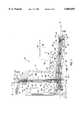
- FIG. 1is a cross-sectional side view of a cabinet treadmill of the instant invention with a tread base positionable between a first incline position and a second incline position, as well as orientable between a first position and a second stored position;
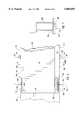
- FIG. 2is a simplified, perspective view of a treadmill with the tread base in the second stored position
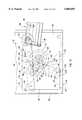
- FIG. 3is a partial side cross-sectional view showing the motor and elevation structure of the treadmill of FIG. 1 with the tread base in a first incline position and in a second stored position;
- FIG. 4is a partial cross-sectional view of portions of the treadmill of FIG. 1 in a second incline position
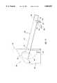
- FIG. 5is a simplified, partial perspective view of selected elements of the structure of FIGS. 3 and 4;
- FIG. 6is a partial top view of portions of the cabinet treadmill of FIG. 1;
- FIG. 7is a partial side view of a motor for use with a treadmill of FIG. 1;
- FIG. 8is an exploded view of the motor of FIG. 1 and associated bracket structure shown in FIGS. 3 and 4;
- FIG. 9is a side view of a portion of the tread base of the treadmill of FIG. 1 with an elevation button;
- FIG. 10is an enlarged, simplified side view of latching structure in the upper portion of the cabinet treadmill of FIG. 1;
- FIG. 11is an enlarged side view of the upper portion of the treadmill of FIG. 1;
- FIG. 12is a simplified, exploded view of portions of the treadmill of FIG. 11;
- FIG. 13is a partial cross-sectional representation of an alternate treadmill having the tread base in a first inclination position and with electrically operable elevation structure;
- FIG. 14is a partial cross-sectional representation of the treadmill of FIG. 13 having the tread base in a second inclination position;
- FIG. 15is a simplified, top cross-sectional view of a portion of the treadmill of FIG. 2;
- FIG. 16is a simplified, side cross-sectional view of a portion of the cover of the treadmill of FIG. 2;
- FIG. 17is a partial, simplified side view of an alternate cabinet treadmill with alternate inclination structure
- FIG. 18is a partial, simplified side view of the alternate cabinet treadmill of FIG. 17 with another alternate inclination structure.
- FIG. 19is a side view of portions of the alternate inclination structure of FIG. 18.
- FIG. 1shows a cabinet treadmill 10 having a freestanding housing 12, as well as a tread base 14.
- the freestanding housing 12has surface engaging means to support the freestanding housing 12 on a support surface.
- the surface engaging means of FIG. 1is shown to be a base 16 which is formed to be generally planar for positioning on a generally planar support surface.
- Inventors skilled in the artwill recognize that other surface-engaging structures may be used, including one or more feet 17 threadedly engaged with the base 16 to be adjustable in height. In one arrangement, feet may be positioned proximate the four corners of the freestanding housing 12. The feet 17 may be used to level the base 16 on the support surface.
- the base 16 or any other surface-engaging structure, such as the feet 17,functions to support the freestanding housing 12 to be, in fact, freestanding when positioned on a support surface.
- the freestanding housing 12has enclosure structure 18 which extends upwardly from the surface-engaging means.
- the enclosure structure 18may be formed in any desirable shape with an open side sized to receive the tread base. In the illustrated arrangement, the enclosure structure 18 is shaped to be rectilinear in projection. Other shapes or configurations may be used as desired.
- the enclosure structure 18has a left side 20 and a right side 22 which as here shown is spaced from and in general alignment with the left side 20.
- the tread base 14also has a left side 24 and a right side 26 (FIG. 2).
- An endless belt 28is positioned between the left side 24 and the right side 26.
- the tread base 14is configured for the performance of treadmill exercises such as walking, jogging or running.
- the tread base 14is orientable between a first position 30 in which the tread base 14 extends away from the freestanding housing 12 with the endless belt 28 positioned to support a user performing exercises thereon. In the second or stored position 32, the tread base 14 is positioned upwardly toward the freestanding housing 12. More specifically, the tread base 14 is reorientable between the first position 30 and the second position 32 in which the tread base 14 is moved toward and positioned substantially within the enclosure structure 18.
- the treadmill 10includes elevation structure 34 positioned forwardly of the tread base 14.
- the elevation structure 34is operable to orient the tread base 14 between a first orientation 38 and a second orientation 40. That is, the tread base 14 is rotatable from the first orientation 38 to the second 40 through angle 42.
- the treadmillalso has a motor 36 that is connected to drive the endless belt 28.
- the cover 78functions as a cabinet door when the tread base 14 is in the second or storage position 32.
- the cover 78is here shown with a left rail 76 and a right rail 77.
- the left rail 76is shown in more detail in FIG. 15.
- the left rail 76 and right rail 77are each formed to extend along the length 430 of the cover 78 and are each similarly formed out of a suitable material such as plastic.
- the left rail 76has an angled edge surface 432 formed to mate with a corresponding edge surface 434 of the side wall 20.
- the right rail 77has an angled edge surface to face a corresponding angled edge surface 436 of the left side wall 22.
- the outer tip 438 of the edge surface 432is positioned to clear the inner surface 440 of the side wall 20 when the tread base 14 is rotated from the stored position 32 toward the first position 30.
- a small gap 442exists between and is defined by the opposing angled surfaces 434 and 432.
- the left rail 76also has a notch 444 formed along its interior side.
- the slot or notch 444is sized to snugly and slidably receive a decorative panel 446.
- the decorative panel 446may be made of any acceptable material such as plastic, formica or plywood.
- the panel 446may have raised portions or indentations formed in various designs and patterns. Other materials may be adhered to the panel 446 including paint, wallpaper or even decorative moldings.
- the left rail 76is shown attached to the left side 24 by any acceptable means including screws, bolts and even adhesives (e.g. thermo plastic glues).
- the left foot 98is also shown attached to the left rail 76 by bolts or screws (not shown) through spacers 448 and 450.
- the left foot 98, as well as the right foot 100function as feet to support the tread base 14 in the first position, and they function as handles for grasping by the user to move the tread base between positions.
- the right rail 77is shown with the panel 446 in the corresponding slot or notch 452.
- An upper cross member 454is shown mounted to extend the width 456 of the door.
- the upper cross member 454has an angled surface 458 that mates or abuts a corresponding angled surface 460 of the upper surface 70 of the enclosure structure 18.
- One or more rubber-like bumpersmay be attached either to surface 460 or surface 458 to act as a cushion and spacer between the surfaces 460 and 458.
- the right foot 100is also shown attached to the right rail 77 by a pair of spacers such as spacer 464.
- FIG. 16also shows a handle 466 which is sized to extend between the left rail 76 and the right rail 77. It may be attached either to the upper cross member 454 as shown or to the left rail 76 and right rail 77.
- the handle 466is shaped with an arcuate exterior surface 468 and an arcuate lower edge 470 to define a recess 472 between the panel 456 and the exterior surface 468.
- the recess 472is sized at its midpoint to accept the fingers of a user. Therefore with the tread base 14 in its first position, the user may reach under the tread base 14 and engage the lip 82 created by the cross member 454. As the user begins to lift the lip 82 upward, the user may engage the handle 466 with the fingers in the recess 470 or as otherwise convenient.
- the usermay also use handles 98 and 100 once the rear 68 of the tread base 14 is elevation above the support surface.
- FIG. 1also shows the cabinet treadmill 10 with handle structure 44 which here consists of a left handle 46 (FIG. 6) and comparable right handle structure 48.
- the handle structure 44is rotatably connected to the tread base 14 and is also movably connected to the freestanding housing 12.
- the handles 46 and 48are firmly mounted with the treadmill 10 in the first orientation or position and movable to a stored configuration when the tread base 14 is oriented into the second or storage position 32.
- FIG. 1also shows a cabinet treadmill 10 with a control arrangement such as control console 50.
- the control console 50is interconnected between the left handle 46 and the right handle 48 through slots 52 formed in the upper end 54 of each of the left handle 46 and right handle 48. That is, a user console 50 may be secured to and between the handles 46 and 48 by another bolt arrangement positioned through or in the slots 52 formed near the end 54 of each of the handles 46 and 48.
- Electrical conductorscan extend through one or both of the handles 46 and 48 and through the left side 24 or right side 26 for operative connection to the motor 36. The conductors are not shown to simplify the drawings.
- a control console 56may be positioned along the back wall 58 of the freestanding housing 12.
- the console 56may be interconnected by conductors 57 to a motor controller 59 which is, in turn, connected by conductors 60 to the motor means 36 and to receive electrical power via plug 52.
- Other control console arrangementsmay be used to present the user with data and controls.
- the console 56may also have a safety switch which includes a card 64 with a lanyard 66 sized for attachment to a user.
- a safety switchwhich includes a card 64 with a lanyard 66 sized for attachment to a user.
- the userinserts the card 64 as a key and attaches the lanyard 66 to his or her person.
- the lanyard 66removes the card 64 to, in turn, turn off the electric motor.
- FIG. 1also shows a gas cylinder 57 optionally in place to provide a force to assist the user in lifting the tread base 14 from the first position 30 toward the second or storage position 32 and in returning the tread base 14 from the storage position 32 to the first position.
- the gas cylinder 57is a conventional gas cylinder rotatably attached at one end 59 to the tread base 14 and to the enclosure structure 18 at its other end 61. More specifically the gas cylinder 57 is rotatably attached to the left side 24 and to the left side or wall 20 of the enclosure structure.
- the gas cylinder 57may also be attached at other locations to provide a force or torque to continuously urge the tread base 14 upward toward the storage position 32.
- the force to be exerted by a user to rotate the tread base 14 between the first position and the storage positionis reduced and set by selecting an appropriately sized gas cylinder.
- the enclosure structure 18also has a top 70 and a back 58 which together form a cabinet into which the tread base 14 is positioned for storage. That is, the tread base 14 is rotated into the second or storage position 32 to be substantially within the enclosure structure 18 as shown in FIG. 1 and as shown in transition in FIG. 2.
- the base 16has a depth 72 and a width 74 which are selected to provide the freestanding housing 12 with a footprint to stably support the freestanding housing 12 and, in turn, the treadmill on a support surface. More specifically, the depth 72 is selected relative to the center of gravity 76 (FIG. 1) of the freestanding housing 12 with the tread base 14 in the second or storage position 32. That is, the depth 72 is selected to not only accommodate all of the structure of the various components as shown in FIG. 1, but also so that a force F 1 applied at or near the top 70 of the freestanding housing 12 will need to be deliberately and specifically applied in order to cause the freestanding housing 12 to tip or rotate on the support surface.
- the width 74is selected so that any force F 2 applied to the freestanding housing 12 at the top 70 will need to be significant in order to cause the freestanding housing with the tread base in the stored position to rotate relative to the support surface.
- Forces F 1 and F 2 in excess of ten (10) pounds and estimated to be in the range of 15 to 30 poundsare contemplated.
- the depth 72 and the width 74 of the freestanding housing 12may vary for different treadmills having tread base of different dimensions, for a typical treadmill having an endless belt 28 with an overall length of about 40 inches or more, a depth 72 from about 18 inches to about 30 inches and a width 74 from about 24 inches to about 36 inches may be found suitable.
- the freestanding housing 12has fully enclosed sides 20 and 22, as well as a fully-enclosed back 58 and top 70.
- the freestanding housing 12constitutes a cabinet into which a tread base 14 is positioned for storage.
- the cabinetmay be fabricated or modified to present a variety of different external appearances in order to be compatible with other furniture items such as bookcases or the like. Indeed, hooks, fasteners or the like may be associated with the side walls 20 and 22 in order to integrate or connect the cabinet within a collection of wall furniture which would include, by way of example, bookcases, stereo cabinets and the like.
- a cover 78is attached to extend between the sides 24 and 26 and between the rear 68 and the front 69.
- the cover 78may be fabricated of any convenient substance to be consistent with, complementary to or the same as the substance used to form the exterior surfaces or walls 20, 22 and rear wall 58 of the freestanding housing 12.
- the underside 78forms a front edge 94 which moves through an arc 95 and over a toe kick 97 from the first position 30 to the second position 32 (FIG. 3). That is, the edge 94 is spaced a distance 101 above the top 103 of the toe kick 97 creating a gap. However, the toe kick 97 is spaced inwardly a distance 105 so that the gap is not easily visible. Further the toe kick and the front edge define a space 99 comparable to that found for many kitchen counter cabinet structures to receive the toes of a user closely approaching the underside 78 so as to, for example, operate the button 322.
- FIGS. 3 and 4the forward end 69 of the tread base 14 as well as the lower portion of the enclosure structure 18 is shown with the associated motor means 36 and elevation structure 34. More particularly, the base 16 is shown with a stiffener 110 which extends between the left side 20 and the right side 22 of the enclosure structure 18. The stiffener 110 is shown held to the base 16 by a plurality of bolts 112 or any acceptable or comparable fastening arrangement.
- a right upright 114 and a left upright 115(FIG. 2) are hollow channels which extend uprightly from the base 16 and above the stiffener 110.
- the right upright 114 and left upright 115both extend a height 116 selected to position the motor means 36 and its related components above the base 16.
- the right upright 114 and left upright 115are reinforced by diagonals 118 and 119 which are welded or otherwise fastened to mounting plates 120 and 121 that are held to the base 16 by a plurality of bolts such as bolt 122 and bolt 124.
- the diagonals 118 and 119are connected at the upper ends 126 and 127 to the uprights 114 and 115, respectively.
- the stiffener 110, the uprights 114 and 115 and the diagonals 118 and 119are all formed from hollow rectilinear channel.
- a base extension 130is rotatably connected to rotate around an axle 132.
- the base extension 130is rotatable about axle 132 between a first position shown in FIG. 3 and a second position shown in FIG. 4. That is, the base extension 130 is mounted to and between the right upright 114 on the left side and the left upright 115 (FIG. 2).
- the left upright 115is comparable in height 116, form and function as that of upright 114. It may be seen that the uprights 114 and 115 also have a stabilizing cross bar 134 attached to extend to between the uprights 114 and 115 to strengthen and support the uprights 114 and 115.
- the base extension 130has a forward groove 136 and a rear groove 138 formed in the top surface 140 to receive screws (not shown) to connect the base extension through other bracket structure to rotate about the axle 132.
- the base extension 130has a left finger 140 and a right finger 142 that extend outwardly for rotatable connection by bolts 144 and 146 to the left side 24 and the right side 26 of the tread base 14.
- the fingers 140 and 142rotatably attach within notches or recesses 148 and 150 formed in sides 24 and 26 so that the exterior surface 152 of the right side 26 and the exterior surface 154 of the left side 24 may be said to be essentially flat or planar.
- the tread base 14has a front roller 154 with the endless belt 28 trained thereabout. More specifically, the tread base 14 has a tread deck 156 mounted by a plurality of rubber-like mounts 158, 160 and 162 to provide a cushioning effect when the user is walking, jogging or running on the endless belt 28 on the tread deck 156.
- the mounts 158, 160 and 162are mounted to a mounting base 164.
- the mounts 158, 160 and 162are spaced to the right side of the tread base 14 and the endless belt 28.
- a comparable plurality of mounts(not shown) are also positioned to the left of the endless belt 28.
- the endless belt 28has an upper stretch 166 and a lower stretch 168. In normal operation, the upper stretch 166 moves from the front roller 154 toward 172 the rear roller 170.
- the lower stretch 168moves from the rear roller 170 toward the front roller 154 in between the left and right rubber mounts such as rubber mounts 158, 160 and 162 and in contact with one or more belt guides 163 (FIG. 15).
- the underside 78contains a supporting cross channel member 174 positioned forwardly with respect to the tread base 14.
- the tread base 14may be rotated from the first position in which it is oriented as shown in FIG. 1 for use by a person performing exercises on the endless belt 28 to a second position in which the tread base 14 is rotated upwardly toward and more specifically within the enclosure structure 18.
- the endless belt 28including the upper stretch 166, the lower stretch 168, as well as the tread deck 156, the mounting base 164 and the underside 78, are all oriented upward and as shown in FIGS. 1, 3 and 4 to be generally upright to act as a closed door of a cabinet.
- the tread base 14is operable between a first incline 38 shown in FIG. 3 and a second incline 40 shown in FIG. 4. That is the inclination or elevation of the tread base 14 relative to a support surface may be varied through angle 42 upon operation of inclination structure.
- the inclination structure illustrated in FIGS. 3 and 4consists of a pneumatic cylinder 180 connected at one end to a bracket 182 by a pin 184. Bracket 182 is secured to the cross member 110 by conventional means including screws, welding and the like.
- the pneumatic cylinder 180is secured at its other end by another bracket 186 which is secured to the underside of the base extension 130 by any acceptable fastening means including pins or the like including, for example, pin 188.
- the pneumatic cylinder 180has a valve 190 which is operable by lever 192.
- the lever 192is moved relative to the bracket 186 by operation of a cable 194 positioned within a sheath 196 fastened to the bracket 186.
- the lever 192moves toward the bracket 186 to operate the valve 190 to in turn cause the pneumatic cylinder to operate, to in turn urge the base extension 130 to rotate upward about bolts 132. That is, operation of the valve 190 operates the pneumatic cylinder 180 in such a fashion that the internal piston shaft 198 extends to urge the deck extension 130 to its upward orientation shown in FIG. 4.
- the deck extension 130is rotatably attached to the front end 69 of the tread deck 14, as better seen in FIG. 6, it can be seen that the tread deck 14 is thereby urged from the first incline 38 to the second incline 40.
- the usermay move his or her weight forward or rearward 172 on the upper stretch 166 of the endless belt 28 to in turn vary the moment arm 199 or torque being exerted about the rear feet 98 and 100 which function as a fulcrum for varying the moment arm associated with the user's weight as the user moves forward or rearward 172 on the endless belt 28.
- the moment arm 199may exceed the upward force applied by the pneumatic cylinder 180 and in turn overcome the force and urge the pneumatic cylinder piston 198 inward into the cylinder housing 200 to vary the inclination between the first inclination 38 and the second inclination 40 and any desired inclination thereinbetween.
- the front roller 154 on the left sidehas a pulley 202 secured thereto.
- the pulley 202is configured to receive a drive belt 204 in a driving relationship with motor means.
- the preferred motor means in FIG. 7is an electric motor 204 with a flywheel 206 mounted to its drive shaft 208.
- a drive pulley 210is also mounted to the drive shaft 208 to drive the pulley 202 via belt 204.
- the flywheel 206is configured to have an increased mass 212 proximate its outer rim to enhance the inertial characteristics thereof.
- the inertia wheel 206is here driven by and functions with the electric motor 204.
- the flywheel 206may be the only motor means involved inasmuch as it operates to deliver energy to drive the endless belt 28 when the user is walking, running or jogging.
- the flywheel 206would receive energy as the user urges the endless belt 28 in the course of walking, jogging or running.
- the flywheel 206 without motor 204receives its energy from the user and delivers that energy to the belt 28 when the user is not delivering energy to the belt when, for example, the user is jogging and in turn not always in contact with the endless belt 28.
- an electric motor 204may be provided to drive the pulley 210 and in turn the belt 204 with or without the flywheel 206.
- the arrangement shown in FIG. 7includes a motor with a flywheel to provide stable rotational energy via the belt 204 to the driven pulley 202.
- the left handle 46is seen attached to the outside 213 of the left side rail 214.
- the right handle 48is attached to the outside 215 of the right side rail 216.
- the handles 46 and 48are rotationally attached to the respective left side rail 214 and right side rail 216 by appropriate structure which includes for example bolt 218 which holds the handle 46 between an appropriate washer 220 and an appropriate wear bushing 224.
- the handles 46 and 48rotate about their respective bolts 218 and 219 as the tread base 14 is rotates from its first position to its second or stored position.
- the pneumatic cylinder 180has a valve 190 which is operated by movement of the lever 192 relative to the bracket 186.
- the movementis effected by operating the cable 194 which is positioned within the sheath 196 in a manner similar to that shown and described in U.S. Pat. No. 5,372,559 the disclosure of which is incorporated herein by reference.
- the cable 194is operated 190 by operation of a foot button 220 positioned in the left side 24 or the right side 26 as desired.
- the corresponding stem 224urges an extension 226 downward.
- the extension 226is connected to the lever 228 which rotates around axis 230.
- the lever 228pulls the cable 194 relative to the sheath 196. That is, the sheath 196 is fixedly secured to a bracket 232 so that the cable 194 moves relative to the sheath 196 to, in turn, cause the valve 190 to operate upon downward 222 movement of the button 200.
- internal pressuresurge the valve 190 to its extended position as shown in FIGS. 3 and 4.
- the cable 194is urged relative to the bracket 232 to urge the button 220 back to its original or upright position generally shown in FIG. 9.
- FIG. 1shows a rear button 220 as well as a forward button 221.
- the forward button 221is structured the same as button 220 and is connected via a separate cable to the lever 192 for operating the lever 192 and in turn the valve 190 the same as button 220.
- a user to raise the elevation of the tread base 14may stand rearwardly on the tread base 14 to vary the leverage or moment about the foot means such as a left foot 98 and right foot 100.
- the internal piston shaft 198may extend to incline the tread base 14.
- the leverage or momentis increased so that the force of extending the internal piston shaft 198 is overcome and the inclination decreased.
- buttons 220 and 221are available for access and operation by a user positioned forwardly and rearwardly and in turn facilitate convenient operation. Indeed the spacing 223 may be selected so that the user must be positioned forwardly on the tread base 14 to operate the forward button 221 and rearwardly to operate the rearward button 220. In other words the buttons 220 and 221 are positioned so the user must position his or her weight forwardly to lower and rearwardly to raise the inclination.
- an electric-powered elevation systemmay be used. That is, a motor may drive a reduction gear to, in turn, rotate a pinion on a rack.
- the rackmay be connected to the base extension 130 and the motor to bracket 182. Upon activation, the pinion moves the rack and, in turn, changes the inclination.
- Other devicesthat employ springs or hydraulics also may be used to vary the inclinations.
- FIGS. 13 and 14illustrate a rack and pinion elevation system. Each is a partial cross-sectional view showing an enclosure structure 350 that has a right side 352, a rear 354 and a bottom 356. A tread base 358 comparable to tread base 14 is shown in a first position 359 in which a user may stand on the tread surface 360. The tread base 358 may be rotated into the enclosure structure 350 to a second or stored position comparable to the second position of the tread base 14.
- the tread base 358is shown in FIG. 13 in a first incline position in which the tread 360 is at a preselected angle or inclination relative to the support surface.
- FIG. 14shows the tread base 358 in a second incline position in which the front end 362 is elevated or higher (relative to a support surface) than when in the first position.
- the front end 362is connected to base extension 364 to rotate about bolts 366 which are comparable to bolts 144 and 146.
- the base extension 364itself is secured to and between spaced apart opposite upright supports 368 by pin 370.
- the upright support 368is secured to bottom 356 by a plurality of screws 372A-D extending through a flange portion 374 of the upright support 368.
- a cross member 376extends between the opposite upright supports 368.
- a motor 379 with an inertia wheel 378has a pulley 380 to power a drive belt (not shown) to in turn drive a pulley 382 at the front end of the tread base 358 in a manner comparable to that shown in FIGS. 3 and 4.
- the motor 379is connected by brackets 382, 384 and 386 comparable to that shown in FIG. 8.
- the base extension 364is shown with a subframe 388 and a cover 390 held in place by bolts 392 and 394 connected to supporting connection brackets 396 and 398.
- the electrically powered elevation structure shown in FIGS. 13 and 14has a motor 400 interconnected through a reduction gear 402.
- a flat strap 404is connected by a bracket 406 to the cross member 376 by a bolt 408 or pin.
- the reduction gear 402is attached to the strap 404 by appropriate screws 410.
- a pinion 412is driven by the motor 400 through the reduction gear 402 to in turn drive a rack 414.
- a rack 414is held in place by a retainer 416 and is rotatably connected by pin or bolt 418 to bracket 420.
- the bracket 420is connected to the base extension 364.
- the useractuates the motor 400 with a switch on a control console such as switch 410 which functions as operations means for operating the elevation structure.
- Poweris thereupon supplied via conductors (not shown) to cause the motor to rotate clockwise or counterclockwise as selected to in turn cause the pinion 412 to rotate on the rack 414 and urge the base extension 364 to rotate about pin 370.
- the front end 362 of the tread basetherefore may be changed in elevation as desired by a user.
- FIGS. 3 and 4also show structure to support the motor means 36 as better seen in FIG. 8. That is, the motor 204 has a connecting bracket 234 connected to the exterior surface 236 of the motor 204 by welding or by any other acceptable means to provide a rigid connection thereinbetween.
- a box bracket 238is sized to fit within the motor bracket 234.
- the box bracket 238has apertures such as apertures 240 sized to correlate to register with apertures such as aperture 242 in bracket 234 for interconnection to the motor bracket 234 by appropriate means such as bolts 244 with associated nuts 246.
- the box bracket 238has a pair of ears 248 and 250, as shown, each having a slot 252 and 256 sized to receive the shaft of a bolt 258 shown in exploded relationship to interconnect with corresponding nut 260.
- the bolt 258 as well as the slots 252 and 256are positioned to register with corresponding apertures 262 and 264 associated and formed in the base bracket 266 which is fixedly secured such as by welding to an attachment bracket 268.
- the attachment bracket 268is secured to the cross support 270 by welding or other means and also to the base extension 130.
- the box bracket 238has a first aperture 272 formed in a left sidewall 274 and a corresponding aperture not shown for purposes of clarity in the right sidewall 276.
- the apertures 272 and its corresponding right aperturereceive the shaft 278 of bolt 280 to rotatably secure therein with a nut 282 the box bracket 238 to the base bracket 266.
- the bolt 258passes through the slots 252 and 256 and may be operated to adjust the tension on the belt 204 to in turn provide an arrangement whereby the belt 204 maintains constant and substantially non-changing tension as the tread base 14 is moved between the first orientation 38 and the second orientation 40 by operation of the inclination structure 34 as hereinbefore discussed.
- the motor bracket 234rotates between a first position shown in FIG. 3 and a second position shown in FIG. 4 as the tread base 14 moves between the first inclination 38 and the second inclination 40.
- the front pulley 154operates about an axle 155 which in turn provides for rotation of the front pulley 154 around axis 157.
- Axis 157is the axis of bolts 146 and 144 and the axis of rotation for fingers 140 and 142.
- the base extension 130has a housing 284 unitarily formed with its upper surface 286 to cover the exposed portion of the driven pulley 202 connected to the front drive pulley 154.
- the tread base 14may be oriented to a second or upright position 32 as shown in FIG. 3.
- the tread base 14has a center of gravity 288 which is positioned to facilitate lifting the tread base from the first position 30 and moving it towards the second position. That is the center of gravity 288 is located toward the center of rotation which is axis 157. With the center of gravity 288 located directly vertically above the axis of rotation 157, the tread base 14 will remain orientated in the second or stored position 32.
- the center of gravity 288may also be oriented counterclockwise relative to the axis of rotation 157 to further enhance the retention of the tread base 14 in the second position by virtue of lever arm developed between displacement of the center of gravity relative to the plane 290 extending vertically upward from the axis 157.
- the center of gravityis located between the front 92 and the middle 289.
- the center of gravity 288may be positioned clockwise relative to the plane 290 with the tread base 14 secured in the second or stored position 32 by a latch or other comparable structure.
- a latching arrangementis provided to latch the tread base 14 to the freestanding housing 12 with the tread base in the second or stored position.
- the latching meanspreferably includes a latching member which may be connected either to the tread base 14 or to the enclosure structure 18.
- the latching memberis a cylindrical bar 300 attached to the left side 24 of the tread base to extend outwardly therefrom for interaction and connection to the lever member 302.
- the lever member 302is rotatably attached by bracket 326 to rotate about axle 304 secured to the top 70 by a bracket 306.
- the lever member 302 as hereinbefore statedmay be secured either to the tread base 14 or to the enclosure structure 18.
- the lever member 302has a first end 308 configured for operation by the user to urge the lever member 302 from its first position as shown in FIG. 10 in solid to a second position 302' shown by dashed lines.
- the lever member 302has a second end 310 opposite the first end 308.
- the second end 310is configured to operatively interact with the latching member 300.
- the latching memberoperates to urge the lever member 302 from the first position to the second position.
- the lever member 302has a receiving portion which is positioned to receive the latching member 300 therewithin and to hold the latching member 300 with the lever member 302 in the first position.
- the lever member 302preferably has a cam surface 314 against which the latching member 300 operates as the tread base is urged towards its second position.
- the receiving portion 312 of the lever member 302is preferably positioned proximate and immediately adjacent the cam surface 314 so that the latching member leaves the cam surface 314 and enters the receiving portion 312 as the tread base 14 is urged into its second position 302'. That is, the latching member 300 is moved 301 to contact the cam surface 314 and force the cam surface 314 and the lever member 302 to rotate about axle 304 from the first position 302 to the second position 302'.
- the latching meanshere illustrated includes spring means to urge the lever member 302 toward the first position 302 from the second position 302'.
- the spring meansis a coil spring 316 positioned between the bracket 306 and the lever member 302.
- the spring 316is configured to compress upon movement of the lever member 302 from the first position 302 to the second position 302' and in turn urge the lever member 302 clockwise against the bumper or spacer 318.
- the top 70preferably has a aperture 320 formed therein so the user may access the lever member 302 for operation.
- a button 322extends from the lever member 302 upward into the aperture 320 so that the user may operate the button 322 by use of a finger. In this way, the user may press downwardly 324 on the button 322 to cause the lever member 302 to rotate 313 about the axis 304 via its related bracket 326 and the related wear washer 328.
- the receiving portion 314is displaced away from the latching member which is pin 300 thereby allowing the latching member 300 to be rotated away from or outwardly from the enclosure structure 18 so that the tread base 14 may in turn be rotated from the second position 32 to the first position 30.
- latching configurationsmay be used as desired including a pin or bolt positioned to extend through the sidewall 20 into the side 24 of the tread base 14.
- Alternate latching arrangementsmay include a ball-detent, a magnetic catch and other devices to inhibit relative movement as between a door and a frame.
- FIG. 11the upper portion of the enclosure structure 18 is shown.
- the right handle 48 and the left handle 46are positioned with their upper end 54 attached to the respective left side 20 and right side 22.
- a right race 330is shown attached to the right side 22 of the enclosure structure 18.
- the left race 332is shown in FIG. 12 with the left handle 46 shown in part.
- An extension 334 sized to snugly and slidably fit within slot 336 of the race 322is attached to the left handle 46.
- the left arm 46is shown with console 343 in place.
- the upper portion of the arm 48includes the slot 52 which is sized to receive nuts or bolts therethrough for further connection to an electronic console 50 as better seen in FIG. 1.
- the right arm 48has a shaft 338 which is similar to shaft 334. Shaft 338 as shown is sized to be snugly slidable within the slot 340 of the right race 330.
- the right handle 48is movable between the first position 48A shown in solid in FIG. 11 which correlates to the first inclination position 38 shown in FIG, 1.
- the handle 40is movable from the first position 48 to a second 48B which correlates to the position of the handle 48 when the wad base 14 has been oriented to the second elevation position 40.
- the handle 48may also be reoriented to the position 48C shown in phantom in FIG. 11 when the tread base 14 is reoriented to the second or storage position 32. That is, as the tread base 14 is rotated upwardly, a force is exerted via the handle 48 on the shafts 338 and 334 to cause them to move in their respective slots 340 and 336 to, in turn, guide the handles 48 and 46 inwardly into the enclosure structure 18 and into a storage position 48C as best seen in FIG. 11.
- the as 330 and 332may be held in place against their respective sides 22 and 20 by plurality of screws or bolts 342. It may be noted that the arrangement of FIG. 11 is configured with the underside 78 positioned within the enclosure as opposed to coextensive with the forward surfaces such as forward surface 82 and 80 as hereinbefore discussed with respect to FIG. 2.
- a cabinet treadmillhas an enclosure structure 480 having a base 482 and opposite sides including right side 484.
- a tread base 486having an endless belt (not shown) and an inertia wheel within the housing 488 is rotatably mounted to the enclosure structure to rotate about bolts such as bolt 490.
- the front edge 492moves in an arc 494 as the tread base 486 is rotatable between a first position 496 in which the tread base 486 is oriented downwardly from the enclosure structure 480 for use by a user and a second or stored position 498 in which the tread base 486 is positioned upwardly within the enclosure structure 18. That is the top 70 sides 20 and 22 together have edges that define a perimeter towards which the underside 78 or door are proximately positioned.
- the treadmill of FIG. 17has rear feet means which support the rear 500 of the tread base 14 on a support surface with the tread base in its first position 496.
- the rear feet meansinclude a pair of spaced apart opposite legs including right leg 502.
- the right leg 502is sized to slidably and snugly move within leg housing 504.
- the leg 502has a plurality of apertures formed in it along its length to register with a corresponding aperture 506 formed in the leg housing 504.
- a pin 508is inserted into the aperture 506 and through a selected corresponding aperture in the leg 502 to vary the inclination of the tread base 486 relative to the support surface.
- a wheel 503is rotatably secured by axle pin 505 to the leg 502.
- FIG. 18shows the treadmill of FIG. 17 with yet another alternative structure to vary the inclination of the tread base 486 when in its first position 496.
- a pair of spaced apart support legs proximate sides of the tread basesupport the tread base on a support surface.
- One such leg 509is shown in FIG. 18. The other is comparably.
- the leg 509 shown in FIG. 18has a generally rectangular planar member 510 which is secured to the tread base 486 in a generally upright vertical orientation.
- the planar member 510may be fabricated of metal and secured to the metal frame of the treadmill by bolts, welding or the like.
- the leg 509has a support 512 that is an elongate planar panel having a first end 514 and a second end 516.
- the first end 514is shaped to be an elongate finger-like extension which functions as a stop for the pawl 518.
- the support 512further has a ratchet section having a plurality of recesses or notches 520 along its perimeter. In the support 512 illustrated in FIG. 18, three distinct notches 520A, 520B and 520C are formed in the perimeter.
- the first notch 520Ais formed by the sides 522, 524 and 526 of the support 512.
- the first notch 520Asubstantially corresponds to the perimeter of a section of the pawl 518 whereby the pawl may be surrounded on a plurality of its sides when that pawl is inserted into the first notch 520A.
- the second notch 520Bis defined by the sides 528 and 530 of the perimeter of the support 512.
- the third notch 520Cis defined by the sides 532 and 534 of the support 512.
- the extension 536may be viewed as being substantially a rectangularly configured section having a longitudinal axis 538 which is oriented to a horizontal axis at an angle A. Given the essentially rectangular configuration of extension 536 it should be understood that linear side 540 would also be oriented at an angle A to the horizontal. In a preferred construction angle A may be within the range of 125 to 136 degrees and preferably 131 degrees.
- the side 522 which extends from side 540is oriented at an angle B from the horizontal.
- angle Bmay be within the range of zero to ten degrees, preferably four degrees.
- Side 524, which extends from side 522is oriented at an angle C from the horizontal.
- Angle Cis within the range of 22 to 34 degrees and preferably approximately 28 degrees.
- Side 526 which extends from side 524is oriented at an angle D from the vertical.
- angle Dmay be within the range of 36 to 48 degrees and preferably 43 degrees.
- Side 528which extends from side 526 is oriented at an angle E from the horizontal.
- angle Eis within the range of four to 15 degrees and preferably nine degrees.
- Side 530extending from side 528, defines an angle F with the vertical.
- Angle Fis preferably within the range of 17 to 29 degrees and preferably 23 degrees.
- Side 532which extends from side 530, is oriented at an angle G from the horizontal.
- Angle Gis within the range of five to fifteen degrees and preferably ten degrees.
- Side 534which extends from side 532 is oriented vertically upright, i.e. at an angle of 90 degrees to the horizontal.
- Sides 526 and 530are dimensioned to provide sufficiently deep notches to enable the top of the pawl 518 to be received in the notches 520B and 520C and form a detachable union with each notch to retain the support in a fixed orientation relative to the exercise apparatus.
- the support 512is rotatably connected to the planar member 510 by means of a pivot axle 542.
- the pivot axle 542is an elongate cylindrical member which extends outwardly and perpendicularly from the surface of the planar member 510.
- the axle 542extends through a circular aperture 544 formed in the support 512.
- the axle 542may be fixedly secured to the planar member 510 while the support 512 is rotatable about the axle 542.
- the axle 542may be fixedly secured to the support 512 and rotatably secured to the planar member 510.
- the axle 542may also be rotatably secured to the planar member 510 while the support 512 is rotatably secured to the axle 542.
- the end 516 of the support 512may be adapted to a connection bar 546 which extends between two spaced apart supports.
- the opposing ends 548 of the bar 546are fitted with end caps 550.
- the end caps 550are preferably fabricated from a material having a high coefficient of friction.
- the end caps 550rest directly on the underlying surface and form the point of contact between the incline adjustment mechanism and the underlying surface.
- the opposite supportsmay be further interconnected to one another by means of a spacer bar 552.
- the pawl 518is a planar member having a somewhat rectangular configuration on one end 554 thereof and an angled surface 556 on its other end 558.
- the pawl 518is rotatably secured to the planar member 510 by a pivot axle 560.
- Axle 560may be configured as an elongate cylindrical shaft which is either fixedly or rotatably secured to the planar member 510 so that the pawl 518 is rotatably with respect to that planar member 510.
- a substantially V-shaped spring 562is secured at its first end 564 to the planar member 510 by means of a pin 566.
- the end 564is formed into a substantially circular configuration which in turn is wrapped around the pin 566.
- the opposing end 568 of the spring 562is also formed into a generally circular configuration which in turn is also secured about a pin 570 which is affixed to the pawl 518.
- the spring 562is constructed to exert a force in the direction of arrow 572. The spring 562 therefore urges the pawl 518, and more specifically, the surface 556 to rotate clockwise into abutment against the support 512 proximate the notches of that support.
- the pawl 518is urged against the perimeter of the support 518 which defines the notches. As the surface 556 of the pawl 518 is urged into one of the notches, the pawl 518 forms a detachable connection with the support 28.
- the support 512When the support 512 engages an underlying surface, such as a floor, the support is urged to rotate in a counterclockwise direction about its pivot axle 542. Should the pawl 518 be secured in notch 520A of the support 512 counterclockwise rotation of support 512 is precluded by the pawl 518. When the end 500 of the treadmill is lifted vertically, the weight of the bar 546 and other components at the end 516 of the support 512 urges the support 512 to rotate clockwise about the axle 542.
- the spring 562is configured such that the force applied to the pawl 518 is less than the torque or force urging clockwise rotation of the support 512.
- a weight 572may be attached to the pawl 518 to urge it to rotate clockwise from notch 520A to notch 520B and 520C, but to rotate counterclockwise when the pawl 518 is urged to a more upright orientation by corner 574.
- the operation of the leg 509is described more fully in U.S. patent application Ser. No. 539,249 filed Oct. 5, 1995, the disclosure of which is incorporated herein by reference.
- the userpositions the tread base 14 in the first position 30 for use.
- the userperforms exercises by positioning himself or herself on the endless belt 28 to commence exercises in the form of walking, jogging or running.
- the treadmillis configured to be electrically powered, the user operates an appropriate on/off switch and other controls conveniently located in a conventional manner as known in the art.
- the usermay operate the buttons 220 or 221 in order to vary the inclination and, in turn, the degree of difficulty of the exercise.
- the userWhen the user is completed, the user lifts the rear end 68 of the tread base 14 upwards towards the second position 32 while operating the button 220 at an appropriate time to lower the front end 69 towards the base 16 as the tread base 14 is rotated inward and toward the second position 32 and is latched in the second position by operation of a latching means as hereinbefore discussed.
Landscapes
- Health & Medical Sciences (AREA)
- Cardiology (AREA)
- Vascular Medicine (AREA)
- General Health & Medical Sciences (AREA)
- Physical Education & Sports Medicine (AREA)
- Rehabilitation Tools (AREA)
Abstract
Description
Claims (11)
Priority Applications (1)
| Application Number | Priority Date | Filing Date | Title |
|---|---|---|---|
| US08/846,942US5860893A (en) | 1996-01-30 | 1997-04-30 | Treadmill with folding handrails |
Applications Claiming Priority (2)
| Application Number | Priority Date | Filing Date | Title |
|---|---|---|---|
| US08/593,799US5704879A (en) | 1996-01-30 | 1996-01-30 | Cabinet treadmill with latch |
| US08/846,942US5860893A (en) | 1996-01-30 | 1997-04-30 | Treadmill with folding handrails |
Related Parent Applications (1)
| Application Number | Title | Priority Date | Filing Date |
|---|---|---|---|
| US08/593,799ContinuationUS5704879A (en) | 1996-01-30 | 1996-01-30 | Cabinet treadmill with latch |
Publications (1)
| Publication Number | Publication Date |
|---|---|
| US5860893Atrue US5860893A (en) | 1999-01-19 |
Family
ID=24376236
Family Applications (2)
| Application Number | Title | Priority Date | Filing Date |
|---|---|---|---|
| US08/593,799Expired - LifetimeUS5704879A (en) | 1996-01-30 | 1996-01-30 | Cabinet treadmill with latch |
| US08/846,942Expired - LifetimeUS5860893A (en) | 1996-01-30 | 1997-04-30 | Treadmill with folding handrails |
Family Applications Before (1)
| Application Number | Title | Priority Date | Filing Date |
|---|---|---|---|
| US08/593,799Expired - LifetimeUS5704879A (en) | 1996-01-30 | 1996-01-30 | Cabinet treadmill with latch |
Country Status (1)
| Country | Link |
|---|---|
| US (2) | US5704879A (en) |
Cited By (104)
| Publication number | Priority date | Publication date | Assignee | Title |
|---|---|---|---|---|
| US6261209B1 (en)* | 1998-05-29 | 2001-07-17 | Fitness Quest, Inc. | Folding exercise treadmill with front inclination |
| US6267710B1 (en)* | 2000-04-12 | 2001-07-31 | Chien-Hsing Liu | Exerciser structure |
| US6273842B1 (en)* | 2000-06-05 | 2001-08-14 | Leao Wang | Electric treadmill with a single motor for adjusting the height of a running board and for folding the treadmill |
| US6461275B1 (en)* | 2000-10-30 | 2002-10-08 | Leao Wang | Elevatingly folding unit of electric exercise treadmill |
| US20020151413A1 (en)* | 1997-10-28 | 2002-10-17 | Dalebout William T. | Fold-out treadmill |
| US20030125165A1 (en)* | 2001-12-31 | 2003-07-03 | Trevino Richard W. | Treadmill |
| US6589138B2 (en) | 2000-05-12 | 2003-07-08 | Precor Incorporated | Treadmill cushion |
| US6610063B2 (en) | 2000-07-28 | 2003-08-26 | Synthes (Usa) | Spinal fixation system |
| US6699159B2 (en)* | 2001-10-11 | 2004-03-02 | J. Robert Rouse | Cam actuated folding treadmill |
| FR2849389A1 (en)* | 2002-12-31 | 2004-07-02 | Forhouse Corp | Inclination mechanism for conveyor belt used for physical exercise has lever arm whose crosspiece is displaced by a control rod of actuating assembly, to change inclination of rolling surface frame |
| US6761667B1 (en) | 2000-02-02 | 2004-07-13 | Icon Ip, Inc. | Hiking exercise apparatus |
| US20040171465A1 (en)* | 2001-09-28 | 2004-09-02 | Patrick Hald | Treadmill belt safety mechanism |
| US20040214693A1 (en)* | 2003-02-28 | 2004-10-28 | Nautilus, Inc. | Dual deck exercise device |
| US20050037898A1 (en)* | 2003-08-11 | 2005-02-17 | Dick Chang | Combination of treadmill and stair climbing machine |
| US20050096188A1 (en)* | 2003-10-29 | 2005-05-05 | James Chen | Folding exercise treadmill with front inclination |
| US20050130807A1 (en)* | 2003-12-11 | 2005-06-16 | Gordon Cutler | Incline trainer |
| US20050148442A1 (en)* | 1996-01-30 | 2005-07-07 | Watterson Scott R. | Reorienting treadmill |
| US20050164838A1 (en)* | 2004-01-09 | 2005-07-28 | Watterson Scott R. | Treadmill with moveable console |
| US20050164839A1 (en)* | 2004-01-09 | 2005-07-28 | Watterson Scott R. | Cushioning treadmill |
| US20050209052A1 (en)* | 2000-02-02 | 2005-09-22 | Ashby Darren C | System and method for selective adjustment of exercise apparatus |
| US20060035755A1 (en)* | 2004-08-11 | 2006-02-16 | Dalebout William T | Elliptical exercise machine with integrated anaerobic exercise system |
| USD527060S1 (en) | 2004-03-22 | 2006-08-22 | Nautilus, Inc. | Exercise device with treadles |
| US20060287161A1 (en)* | 2004-08-11 | 2006-12-21 | Dalebout William T | Foldable elliptical exercise machine |
| US20070027003A1 (en)* | 2005-08-01 | 2007-02-01 | Fitness Quest Inc. | Exercise treadmill |
| US20070049464A1 (en)* | 2005-08-26 | 2007-03-01 | Ming-Fu Chou | Folding device for treadmills |
| WO2007072180A3 (en)* | 2005-12-22 | 2007-10-04 | Club Design S R L | Furniture module containing fitness equipement |
| EP1870137A1 (en)* | 2006-06-21 | 2007-12-26 | Hai-Pin Kuo | Foldable treadmill |
| US20080200314A1 (en)* | 2007-02-20 | 2008-08-21 | Icon Health And Fitness, Inc. | One-step foldable elliptical exercise machine |
| US20080300114A1 (en)* | 2007-06-04 | 2008-12-04 | Dalebout William T | Elliptical exercise machine with adjustable ramp |
| US20090005224A1 (en)* | 2007-06-27 | 2009-01-01 | Johnson Health Tech Co., Ltd | Foldable treadmill |
| US7537549B2 (en) | 2000-02-02 | 2009-05-26 | Icon Ip, Inc. | Incline assembly with cam |
| US20090137367A1 (en)* | 2000-02-02 | 2009-05-28 | Icon Ip, Inc. | Inclining treadmill with magnetic braking system |
| US7658698B2 (en) | 2006-08-02 | 2010-02-09 | Icon Ip, Inc. | Variable stride exercise device with ramp |
| US7674205B2 (en) | 2007-05-08 | 2010-03-09 | Icon Ip, Inc. | Elliptical exercise machine with adjustable foot motion |
| US7717828B2 (en) | 2006-08-02 | 2010-05-18 | Icon Ip, Inc. | Exercise device with pivoting assembly |
| US7972249B1 (en)* | 2010-06-02 | 2011-07-05 | Napalan Paulito B | Gym apparatus |
| USRE42698E1 (en) | 2001-07-25 | 2011-09-13 | Nautilus, Inc. | Treadmill having dual treads for stepping exercises |
| WO2013074243A1 (en) | 2011-11-15 | 2013-05-23 | Icon Health & Fitness, Inc. | Exercise device with rack and pinion incline adjusting mechanism |
| US8690735B2 (en) | 1999-07-08 | 2014-04-08 | Icon Health & Fitness, Inc. | Systems for interaction with exercise device |
| US8758201B2 (en) | 1999-07-08 | 2014-06-24 | Icon Health & Fitness, Inc. | Portable physical activity sensing system |
| US9028368B2 (en) | 1999-07-08 | 2015-05-12 | Icon Health & Fitness, Inc. | Systems, methods, and devices for simulating real world terrain on an exercise device |
| US9174085B2 (en) | 2012-07-31 | 2015-11-03 | John Paul Foley | Exercise system and method |
| CN107866035A (en)* | 2017-12-20 | 2018-04-03 | 浙江正星健身器有限公司 | A kind of handrail foldable structure of treadmill |
| US10188890B2 (en) | 2013-12-26 | 2019-01-29 | Icon Health & Fitness, Inc. | Magnetic resistance mechanism in a cable machine |
| US10220259B2 (en) | 2012-01-05 | 2019-03-05 | Icon Health & Fitness, Inc. | System and method for controlling an exercise device |
| US10226396B2 (en) | 2014-06-20 | 2019-03-12 | Icon Health & Fitness, Inc. | Post workout massage device |
| US10252109B2 (en) | 2016-05-13 | 2019-04-09 | Icon Health & Fitness, Inc. | Weight platform treadmill |
| US10258828B2 (en) | 2015-01-16 | 2019-04-16 | Icon Health & Fitness, Inc. | Controls for an exercise device |
| US10272317B2 (en) | 2016-03-18 | 2019-04-30 | Icon Health & Fitness, Inc. | Lighted pace feature in a treadmill |
| US10279212B2 (en) | 2013-03-14 | 2019-05-07 | Icon Health & Fitness, Inc. | Strength training apparatus with flywheel and related methods |
| US10293211B2 (en) | 2016-03-18 | 2019-05-21 | Icon Health & Fitness, Inc. | Coordinated weight selection |
| US20190192898A1 (en)* | 2017-12-22 | 2019-06-27 | Icon Health & Fitness, Inc. | Inclinable Exercise Machine |
| US10335632B2 (en) | 2015-12-31 | 2019-07-02 | Nautilus, Inc. | Treadmill including a deck locking mechanism |
| US10343017B2 (en) | 2016-11-01 | 2019-07-09 | Icon Health & Fitness, Inc. | Distance sensor for console positioning |
| US10376736B2 (en) | 2016-10-12 | 2019-08-13 | Icon Health & Fitness, Inc. | Cooling an exercise device during a dive motor runway condition |
| US10391361B2 (en) | 2015-02-27 | 2019-08-27 | Icon Health & Fitness, Inc. | Simulating real-world terrain on an exercise device |
| US10398932B2 (en) | 2015-12-31 | 2019-09-03 | Nautilus, Inc. | Treadmill including a lift assistance mechanism |
| US10426989B2 (en) | 2014-06-09 | 2019-10-01 | Icon Health & Fitness, Inc. | Cable system incorporated into a treadmill |
| US10433612B2 (en) | 2014-03-10 | 2019-10-08 | Icon Health & Fitness, Inc. | Pressure sensor to quantify work |
| US10441844B2 (en) | 2016-07-01 | 2019-10-15 | Icon Health & Fitness, Inc. | Cooling systems and methods for exercise equipment |
| US10441840B2 (en) | 2016-03-18 | 2019-10-15 | Icon Health & Fitness, Inc. | Collapsible strength exercise machine |
| US10449416B2 (en) | 2015-08-26 | 2019-10-22 | Icon Health & Fitness, Inc. | Strength exercise mechanisms |
| US10471299B2 (en) | 2016-07-01 | 2019-11-12 | Icon Health & Fitness, Inc. | Systems and methods for cooling internal exercise equipment components |
| US10493349B2 (en) | 2016-03-18 | 2019-12-03 | Icon Health & Fitness, Inc. | Display on exercise device |
| US10500473B2 (en) | 2016-10-10 | 2019-12-10 | Icon Health & Fitness, Inc. | Console positioning |
| US10543395B2 (en) | 2016-12-05 | 2020-01-28 | Icon Health & Fitness, Inc. | Offsetting treadmill deck weight during operation |
| US10561893B2 (en) | 2016-10-12 | 2020-02-18 | Icon Health & Fitness, Inc. | Linear bearing for console positioning |
| US10561894B2 (en) | 2016-03-18 | 2020-02-18 | Icon Health & Fitness, Inc. | Treadmill with removable supports |
| US10625137B2 (en) | 2016-03-18 | 2020-04-21 | Icon Health & Fitness, Inc. | Coordinated displays in an exercise device |
| US10625114B2 (en) | 2016-11-01 | 2020-04-21 | Icon Health & Fitness, Inc. | Elliptical and stationary bicycle apparatus including row functionality |
| US10661114B2 (en) | 2016-11-01 | 2020-05-26 | Icon Health & Fitness, Inc. | Body weight lift mechanism on treadmill |
| US10671705B2 (en) | 2016-09-28 | 2020-06-02 | Icon Health & Fitness, Inc. | Customizing recipe recommendations |
| US10729965B2 (en) | 2017-12-22 | 2020-08-04 | Icon Health & Fitness, Inc. | Audible belt guide in a treadmill |
| US10786706B2 (en) | 2018-07-13 | 2020-09-29 | Icon Health & Fitness, Inc. | Cycling shoe power sensors |
| US10918905B2 (en) | 2016-10-12 | 2021-02-16 | Icon Health & Fitness, Inc. | Systems and methods for reducing runaway resistance on an exercise device |
| US10940360B2 (en) | 2015-08-26 | 2021-03-09 | Icon Health & Fitness, Inc. | Strength exercise mechanisms |
| US10953305B2 (en) | 2015-08-26 | 2021-03-23 | Icon Health & Fitness, Inc. | Strength exercise mechanisms |
| US11000730B2 (en) | 2018-03-16 | 2021-05-11 | Icon Health & Fitness, Inc. | Elliptical exercise machine |
| US11033777B1 (en) | 2019-02-12 | 2021-06-15 | Icon Health & Fitness, Inc. | Stationary exercise machine |
| US11058914B2 (en) | 2016-07-01 | 2021-07-13 | Icon Health & Fitness, Inc. | Cooling methods for exercise equipment |
| US11187285B2 (en) | 2017-12-09 | 2021-11-30 | Icon Health & Fitness, Inc. | Systems and methods for selectively rotationally fixing a pedaled drivetrain |
| US11244751B2 (en) | 2012-10-19 | 2022-02-08 | Finish Time Holdings, Llc | Method and device for providing a person with training data of an athlete as the athlete is performing a swimming workout |
| US11298577B2 (en) | 2019-02-11 | 2022-04-12 | Ifit Inc. | Cable and power rack exercise machine |
| US11326673B2 (en) | 2018-06-11 | 2022-05-10 | Ifit Inc. | Increased durability linear actuator |
| US11451108B2 (en) | 2017-08-16 | 2022-09-20 | Ifit Inc. | Systems and methods for axial impact resistance in electric motors |
| US11534654B2 (en) | 2019-01-25 | 2022-12-27 | Ifit Inc. | Systems and methods for an interactive pedaled exercise device |
| US11534651B2 (en) | 2019-08-15 | 2022-12-27 | Ifit Inc. | Adjustable dumbbell system |
| US11610664B2 (en) | 2012-07-31 | 2023-03-21 | Peloton Interactive, Inc. | Exercise system and method |
| US11673036B2 (en) | 2019-11-12 | 2023-06-13 | Ifit Inc. | Exercise storage system |
| US11794070B2 (en) | 2019-05-23 | 2023-10-24 | Ifit Inc. | Systems and methods for cooling an exercise device |
| US11850497B2 (en) | 2019-10-11 | 2023-12-26 | Ifit Inc. | Modular exercise device |
| US11878199B2 (en) | 2021-02-16 | 2024-01-23 | Ifit Inc. | Safety mechanism for an adjustable dumbbell |
| US11931621B2 (en) | 2020-03-18 | 2024-03-19 | Ifit Inc. | Systems and methods for treadmill drift avoidance |
| US11951377B2 (en) | 2020-03-24 | 2024-04-09 | Ifit Inc. | Leaderboard with irregularity flags in an exercise machine system |
| US12029961B2 (en) | 2020-03-24 | 2024-07-09 | Ifit Inc. | Flagging irregularities in user performance in an exercise machine system |
| US12029935B2 (en) | 2021-08-19 | 2024-07-09 | Ifit Inc. | Adjustment mechanism for an adjustable kettlebell |
| US12176009B2 (en) | 2021-12-30 | 2024-12-24 | Ifit Inc. | Systems and methods for synchronizing workout equipment with video files |
| US12219201B2 (en) | 2021-08-05 | 2025-02-04 | Ifit Inc. | Synchronizing video workout programs across multiple devices |
| US12263371B2 (en) | 2021-04-27 | 2025-04-01 | Ifit Inc. | Devices, systems, and methods for rotating a tread belt in two directions |
| US12280294B2 (en) | 2021-10-15 | 2025-04-22 | Ifit Inc. | Magnetic clutch for a pedaled drivetrain |
| US12350573B2 (en) | 2021-04-27 | 2025-07-08 | Ifit Inc. | Systems and methods for cross-training on exercise devices |
| US12350547B2 (en) | 2022-02-28 | 2025-07-08 | Ifit Inc. | Devices, systems, and methods for moving a movable step through a transition zone |
| US12409375B2 (en) | 2022-03-18 | 2025-09-09 | Ifit Inc. | Systems and methods for haptic simulation in incline exercise devices |
| US12433815B2 (en) | 2020-10-02 | 2025-10-07 | Ifit Inc. | Massage roller with pressure sensors |
Families Citing this family (9)
| Publication number | Priority date | Publication date | Assignee | Title |
|---|---|---|---|---|
| US5868648A (en) | 1996-05-13 | 1999-02-09 | Ff Acquisition Corp. | Foldable treadmill apparatus and method |
| US5830113A (en) | 1996-05-13 | 1998-11-03 | Ff Acquisition Corp. | Foldable treadmill and bench apparatus and method |
| US5855537A (en) | 1996-11-12 | 1999-01-05 | Ff Acquisition Corp. | Powered folding treadmill apparatus and method |
| US6808475B2 (en)* | 2002-10-07 | 2004-10-26 | Kehrbaum John M | Ergonomic computer workstation and treadmill combination |
| US7736280B2 (en)* | 2004-08-17 | 2010-06-15 | Nautilus, Inc. | Treadmill deck locking mechanism |
| US20080234111A1 (en)* | 2007-03-20 | 2008-09-25 | David Austin Packham | Mid-deck hinged treadmill deck |
| US20080280734A1 (en)* | 2007-05-09 | 2008-11-13 | Spark Innovations, Inc. | Folding treadmill |
| TWM400335U (en) | 2010-09-20 | 2011-03-21 | Rexon Ind Corp Ltd | Folding treadmill |
| US9795827B2 (en)* | 2014-09-12 | 2017-10-24 | Thermogenesis Group, Inc. | Retractable treadmill desk |
Citations (2)
| Publication number | Priority date | Publication date | Assignee | Title |
|---|---|---|---|---|
| US931394A (en)* | 1909-04-28 | 1909-08-17 | Alfred Day | Exercising device. |
| US5344372A (en)* | 1993-11-15 | 1994-09-06 | Michael Hung | Treadmill with collapsible handrails |
Family Cites Families (65)
| Publication number | Priority date | Publication date | Assignee | Title |
|---|---|---|---|---|
| DE83466C (en)* | ||||
| US321388A (en)* | 1885-06-30 | ruebsam | ||
| US3127171A (en)* | 1964-03-31 | figure | ||
| US663486A (en)* | 1899-08-07 | 1900-12-11 | Alfred Boren | Combined folding chair and couch. |
| US881521A (en)* | 1906-12-24 | 1908-03-10 | Stephen G Wilson | Mechanical chair. |
| US1020777A (en)* | 1909-07-26 | 1912-03-19 | John Peterson | Music-bench. |
| US1082940A (en)* | 1913-03-01 | 1913-12-30 | Sharp & Smith | Exercising appliance. |
| GB307116A (en)* | 1927-12-07 | 1929-03-07 | William Augustine Spain | Improvements in rowing machines |
| US1850530A (en)* | 1929-05-10 | 1932-03-22 | George K Brown | Exercising apparatus |
| US1928089A (en)* | 1929-07-29 | 1933-09-26 | Blickman Inc | Exercising apparatus |
| US1902694A (en)* | 1932-02-08 | 1933-03-21 | Reid A Edwards | Gymnastic apparatus |
| US1973945A (en)* | 1933-06-30 | 1934-09-18 | Marion I Chavin | Combination exercising and massaging apparatus |
| US2855200A (en)* | 1955-12-01 | 1958-10-07 | Blickman Harry | Home exercising apparatus |
| US2874971A (en)* | 1955-12-23 | 1959-02-24 | Philco Corp | Appliance cabinet structure |
| US3378259A (en)* | 1964-11-13 | 1968-04-16 | Edward C. Kupchinski | Exercising cot |
| NO117726B (en)* | 1967-07-01 | 1969-09-15 | Johannes Oestensjoe & Co A S | |
| US3589715A (en)* | 1968-10-07 | 1971-06-29 | Morris Mark | Convertible foldable exercise cot |
| US3614097A (en)* | 1969-01-28 | 1971-10-19 | Blickman Inc | Weight lifting exercising apparatus |
| NO125477B (en)* | 1969-07-17 | 1972-09-18 | Arnold Selnes | |
| US3659845A (en)* | 1970-04-10 | 1972-05-02 | Quinton Instr | Exercise treadmill and belt support apparatus |
| US3874657A (en)* | 1970-06-04 | 1975-04-01 | Frank J Niebojewski | Exercise apparatus including stall bars and exercise equipment mounted thereon |
| US3738649A (en)* | 1970-11-16 | 1973-06-12 | E Miller | Combined chair and exercising device |
| US3731917A (en)* | 1971-02-25 | 1973-05-08 | Townsend Engineering Co | Treadmill exercising device |
| US3741538A (en)* | 1971-03-22 | 1973-06-26 | R Useldinger | Friction type exercising device mounted on a collapsible structure |
| FR2151551A5 (en)* | 1971-09-03 | 1973-04-20 | Jouk Leo | |
| SE366645B (en)* | 1971-12-02 | 1974-05-06 | Landstingens Inkopscentral | |
| US3751033A (en)* | 1971-12-15 | 1973-08-07 | W Rosenthal | Combination of a chair and pedaling device |
| US3826491A (en)* | 1973-06-18 | 1974-07-30 | Del Mar Eng Lab | Exercise treadmill |
| DE2408052C3 (en)* | 1974-02-20 | 1978-04-13 | Suspa-Federungstechnik Fritz Bauer & Soehne Ohg, 8503 Altdorf | Length-adjustable gas spring |
| US3892404A (en)* | 1974-10-30 | 1975-07-01 | Theodore Martucci | Exercise device |
| US4066257A (en)* | 1975-11-07 | 1978-01-03 | Moller Bynum W | Treadmill exercising device |
| US4026545A (en)* | 1975-11-25 | 1977-05-31 | Schoenenberger Rolf | Physical exercise apparatus |
| US4248476A (en)* | 1978-12-11 | 1981-02-03 | Phelps Melvin B | Convertible seat assembly |
| JPS5628714A (en)* | 1979-08-20 | 1981-03-20 | Tokico Ltd | Locking chair |
| JPS5935735B2 (en)* | 1979-10-09 | 1984-08-30 | 本田技研工業株式会社 | Temporary fixing method and device for thin-walled workpieces |
| JPS56150562A (en)* | 1980-04-23 | 1981-11-21 | Matsushita Electric Ind Co Ltd | Detector for bubble |
| US4300761A (en)* | 1980-10-06 | 1981-11-17 | Howard William E | Spring type exercising device |
| USD270555S (en) | 1981-11-16 | 1983-09-13 | Ralph Ogden | Exercise treadmill |
| US4422635A (en)* | 1982-01-27 | 1983-12-27 | Herod James V | Portable multiple use exerciser |
| DE3370140D1 (en)* | 1982-05-25 | 1987-04-16 | Brown Fitzpatrick Lloyd Patent | Convertible exercising apparatus |
| USD283239S (en) | 1984-01-19 | 1986-04-01 | Precor, Incorporated | Exercise treadmill |
| US4591147A (en)* | 1984-09-06 | 1986-05-27 | Precor Incorporated | System for elevating an exercise treadmill |
| US4625962A (en)* | 1984-10-22 | 1986-12-02 | The Cleveland Clinic Foundation | Upper body exercise apparatus |
| US4664646A (en)* | 1985-01-25 | 1987-05-12 | Rorabaugh Barre L | Treadmill motor drive |
| USD284597S (en) | 1985-01-29 | 1986-07-08 | Precor Incorporated | Inclined physical exerciser |
| US4679787A (en)* | 1985-02-14 | 1987-07-14 | The Stouffer Corporation | Combined exercise station and sleeping bed |
| US4635928A (en)* | 1985-04-15 | 1987-01-13 | Ajax Enterprises Corporation | Adjustable speed control arrangement for motorized exercise treadmills |
| US4729558A (en)* | 1985-10-11 | 1988-03-08 | Kuo Hai P | Running exerciser |
| US4921247A (en)* | 1986-08-11 | 1990-05-01 | Sterling Joseph F | Exercise chair |
| US4776582A (en)* | 1986-10-09 | 1988-10-11 | M & R Industries, Inc. | Exercise treadmill with adjustable slope |
| US4813743A (en)* | 1987-06-30 | 1989-03-21 | Mizelle Ned W | Reclining back mechanism for a seating unit |
| US4759540A (en)* | 1986-10-14 | 1988-07-26 | Industrial Technology Research Institute | Compact structure for a treadmill |
| US4709918A (en)* | 1986-12-29 | 1987-12-01 | Arkady Grinblat | Universal exercising apparatus |
| US4826153A (en)* | 1987-03-02 | 1989-05-02 | Schalip John D | Portable folding freestanding gym |
| US4805901A (en)* | 1987-04-09 | 1989-02-21 | Kulick John M | Collapsible exercise device |
| US5002271A (en)* | 1988-05-17 | 1991-03-26 | Gonzales Ike T | Portable leg exerciser |
| US4913423A (en)* | 1988-06-06 | 1990-04-03 | Farran Mitchell R | Exercise furniture |
| US5192255B1 (en)* | 1988-10-12 | 1995-01-31 | Citicorp North America Inc | Adjustable incline system for exercise equipment |
| US4913396B2 (en)* | 1988-10-12 | 1995-06-20 | Weslo Inc | Adjustable incline system for exercise equipment |
| US5029801A (en)* | 1988-10-12 | 1991-07-09 | Proform Fitness Products, Inc. | Adjustable incline system for exercise equipment |
| US4905330A (en)* | 1989-02-23 | 1990-03-06 | Jacobs Lawrence I | Combination furniture and exercise device |
| US5163885A (en)* | 1990-07-30 | 1992-11-17 | Precor Incorporated | Integrated drive and elevation system for exercise apparatus |
| US5109778A (en)* | 1991-04-29 | 1992-05-05 | Berco Industries | Folding table |
| US5207628A (en)* | 1991-11-18 | 1993-05-04 | Graham Otha O | Suspending fold-away bed exercising device |
| US5352167A (en)* | 1993-06-08 | 1994-10-04 | Ecm Motor Co. | Inclination drive mechanism for a treadmill |
- 1996
- 1996-01-30USUS08/593,799patent/US5704879A/ennot_activeExpired - Lifetime
- 1997
- 1997-04-30USUS08/846,942patent/US5860893A/ennot_activeExpired - Lifetime
Patent Citations (2)
| Publication number | Priority date | Publication date | Assignee | Title |
|---|---|---|---|---|
| US931394A (en)* | 1909-04-28 | 1909-08-17 | Alfred Day | Exercising device. |
| US5344372A (en)* | 1993-11-15 | 1994-09-06 | Michael Hung | Treadmill with collapsible handrails |
Cited By (192)
| Publication number | Priority date | Publication date | Assignee | Title |
|---|---|---|---|---|
| US20050148443A1 (en)* | 1996-01-30 | 2005-07-07 | Watterson Scott R. | Reorienting treadmill |
| US20050148442A1 (en)* | 1996-01-30 | 2005-07-07 | Watterson Scott R. | Reorienting treadmill |
| US7540828B2 (en) | 1996-01-30 | 2009-06-02 | Icon Ip, Inc. | Reorienting treadmill |
| US7192388B2 (en) | 1997-10-28 | 2007-03-20 | Icon Health & Fitness, Inc. | Fold-out treadmill |
| US20020151413A1 (en)* | 1997-10-28 | 2002-10-17 | Dalebout William T. | Fold-out treadmill |
| US6261209B1 (en)* | 1998-05-29 | 2001-07-17 | Fitness Quest, Inc. | Folding exercise treadmill with front inclination |
| US9028368B2 (en) | 1999-07-08 | 2015-05-12 | Icon Health & Fitness, Inc. | Systems, methods, and devices for simulating real world terrain on an exercise device |
| US8690735B2 (en) | 1999-07-08 | 2014-04-08 | Icon Health & Fitness, Inc. | Systems for interaction with exercise device |
| US8758201B2 (en) | 1999-07-08 | 2014-06-24 | Icon Health & Fitness, Inc. | Portable physical activity sensing system |
| US8784270B2 (en) | 1999-07-08 | 2014-07-22 | Icon Ip, Inc. | Portable physical activity sensing system |
| US8876668B2 (en) | 2000-02-02 | 2014-11-04 | Icon Ip, Inc. | Exercise device with magnetic braking system |
| US6761667B1 (en) | 2000-02-02 | 2004-07-13 | Icon Ip, Inc. | Hiking exercise apparatus |
| US7645212B2 (en) | 2000-02-02 | 2010-01-12 | Icon Ip, Inc. | System and method for selective adjustment of exercise apparatus |
| US20050209052A1 (en)* | 2000-02-02 | 2005-09-22 | Ashby Darren C | System and method for selective adjustment of exercise apparatus |
| US20090137367A1 (en)* | 2000-02-02 | 2009-05-28 | Icon Ip, Inc. | Inclining treadmill with magnetic braking system |
| US7537549B2 (en) | 2000-02-02 | 2009-05-26 | Icon Ip, Inc. | Incline assembly with cam |
| US7862483B2 (en) | 2000-02-02 | 2011-01-04 | Icon Ip, Inc. | Inclining treadmill with magnetic braking system |
| US20110152039A1 (en)* | 2000-02-02 | 2011-06-23 | Icon Ip, Inc. | Exercise device with magnetic braking system |
| US9623281B2 (en) | 2000-02-02 | 2017-04-18 | Icon Health & Fitness, Inc. | Exercise device with braking system |
| US6267710B1 (en)* | 2000-04-12 | 2001-07-31 | Chien-Hsing Liu | Exerciser structure |
| US6589138B2 (en) | 2000-05-12 | 2003-07-08 | Precor Incorporated | Treadmill cushion |
| US6273842B1 (en)* | 2000-06-05 | 2001-08-14 | Leao Wang | Electric treadmill with a single motor for adjusting the height of a running board and for folding the treadmill |
| US20070055243A1 (en)* | 2000-07-28 | 2007-03-08 | Synthes (Usa) | Spinal fixation system |
| US20040039386A1 (en)* | 2000-07-28 | 2004-02-26 | Synthes (Usa) | Spinal fixation system |
| US8221470B2 (en) | 2000-07-28 | 2012-07-17 | Synthes Usa, Llc | Spinal fixation system |
| US9504499B2 (en) | 2000-07-28 | 2016-11-29 | DePuy Synthes Products, Inc. | Spinal fixation system |
| US7118571B2 (en) | 2000-07-28 | 2006-10-10 | Synthes (U.S.A.) | Spinal fixation system |
| US8551146B2 (en) | 2000-07-28 | 2013-10-08 | DePuy Synthes Products, LLC | Spinal fixation system |
| US20100042166A1 (en)* | 2000-07-28 | 2010-02-18 | Kumar Kris G | Spinal fixation system |
| US6610063B2 (en) | 2000-07-28 | 2003-08-26 | Synthes (Usa) | Spinal fixation system |
| US6461275B1 (en)* | 2000-10-30 | 2002-10-08 | Leao Wang | Elevatingly folding unit of electric exercise treadmill |
| USRE42698E1 (en) | 2001-07-25 | 2011-09-13 | Nautilus, Inc. | Treadmill having dual treads for stepping exercises |
| US20040171465A1 (en)* | 2001-09-28 | 2004-09-02 | Patrick Hald | Treadmill belt safety mechanism |
| US6699159B2 (en)* | 2001-10-11 | 2004-03-02 | J. Robert Rouse | Cam actuated folding treadmill |
| US20030125165A1 (en)* | 2001-12-31 | 2003-07-03 | Trevino Richard W. | Treadmill |
| US20070054780A1 (en)* | 2001-12-31 | 2007-03-08 | Hebb Industries, Inc. | Treadmill |
| US7544153B2 (en) | 2001-12-31 | 2009-06-09 | Nautilus, Inc. | Treadmill |
| US7455626B2 (en) | 2001-12-31 | 2008-11-25 | Nautilus, Inc. | Treadmill |
| FR2849389A1 (en)* | 2002-12-31 | 2004-07-02 | Forhouse Corp | Inclination mechanism for conveyor belt used for physical exercise has lever arm whose crosspiece is displaced by a control rod of actuating assembly, to change inclination of rolling surface frame |
| US20040214693A1 (en)* | 2003-02-28 | 2004-10-28 | Nautilus, Inc. | Dual deck exercise device |
| US20050037898A1 (en)* | 2003-08-11 | 2005-02-17 | Dick Chang | Combination of treadmill and stair climbing machine |
| US7097593B2 (en) | 2003-08-11 | 2006-08-29 | Nautilus, Inc. | Combination of treadmill and stair climbing machine |
| US6926644B2 (en)* | 2003-10-29 | 2005-08-09 | James Chen | Folding exercise treadmill with front inclination |
| US20050096188A1 (en)* | 2003-10-29 | 2005-05-05 | James Chen | Folding exercise treadmill with front inclination |
| US7285075B2 (en) | 2003-12-11 | 2007-10-23 | Icon Ip, Inc. | Incline trainer |
| US20050130807A1 (en)* | 2003-12-11 | 2005-06-16 | Gordon Cutler | Incline trainer |
| US20050164838A1 (en)* | 2004-01-09 | 2005-07-28 | Watterson Scott R. | Treadmill with moveable console |
| US20050164839A1 (en)* | 2004-01-09 | 2005-07-28 | Watterson Scott R. | Cushioning treadmill |
| US7344481B2 (en) | 2004-01-09 | 2008-03-18 | Icon Ip, Inc. | Treadmill with moveable console |
| USD527060S1 (en) | 2004-03-22 | 2006-08-22 | Nautilus, Inc. | Exercise device with treadles |
| US7909740B2 (en) | 2004-08-11 | 2011-03-22 | Icon Ip, Inc. | Elliptical exercise machine with integrated aerobic exercise system |
| US20080167163A9 (en)* | 2004-08-11 | 2008-07-10 | Icon Ip, Inc. | Folding elliptical exercise machine |
| US20080153674A9 (en)* | 2004-08-11 | 2008-06-26 | Dalebout William T | Foldable elliptical exercise machine |
| US20060035755A1 (en)* | 2004-08-11 | 2006-02-16 | Dalebout William T | Elliptical exercise machine with integrated anaerobic exercise system |
| US20060287161A1 (en)* | 2004-08-11 | 2006-12-21 | Dalebout William T | Foldable elliptical exercise machine |
| US20070129218A1 (en)* | 2004-08-11 | 2007-06-07 | Icon Ip, Inc. | Folding elliptical exercise machine |
| US7740563B2 (en) | 2004-08-11 | 2010-06-22 | Icon Ip, Inc. | Elliptical exercise machine with integrated anaerobic exercise system |
| US7766797B2 (en) | 2004-08-11 | 2010-08-03 | Icon Ip, Inc. | Breakaway or folding elliptical exercise machine |
| US7775940B2 (en) | 2004-08-11 | 2010-08-17 | Icon Ip, Inc. | Folding elliptical exercise machine |
| US7367926B2 (en) | 2005-08-01 | 2008-05-06 | Fitness Quest Inc. | Exercise treadmill |
| US20070027003A1 (en)* | 2005-08-01 | 2007-02-01 | Fitness Quest Inc. | Exercise treadmill |
| US20070049464A1 (en)* | 2005-08-26 | 2007-03-01 | Ming-Fu Chou | Folding device for treadmills |
| WO2007072180A3 (en)* | 2005-12-22 | 2007-10-04 | Club Design S R L | Furniture module containing fitness equipement |
| EP1870137A1 (en)* | 2006-06-21 | 2007-12-26 | Hai-Pin Kuo | Foldable treadmill |
| US7658698B2 (en) | 2006-08-02 | 2010-02-09 | Icon Ip, Inc. | Variable stride exercise device with ramp |
| US7717828B2 (en) | 2006-08-02 | 2010-05-18 | Icon Ip, Inc. | Exercise device with pivoting assembly |
| US7736279B2 (en)* | 2007-02-20 | 2010-06-15 | Icon Ip, Inc. | One-step foldable elliptical exercise machine |
| US20080200314A1 (en)* | 2007-02-20 | 2008-08-21 | Icon Health And Fitness, Inc. | One-step foldable elliptical exercise machine |
| US20100242246A1 (en)* | 2007-02-20 | 2010-09-30 | Icon Ip, Inc. | One-step foldable elliptical exercise machine |
| US7674205B2 (en) | 2007-05-08 | 2010-03-09 | Icon Ip, Inc. | Elliptical exercise machine with adjustable foot motion |
| US7618350B2 (en) | 2007-06-04 | 2009-11-17 | Icon Ip, Inc. | Elliptical exercise machine with adjustable ramp |
| US20080300114A1 (en)* | 2007-06-04 | 2008-12-04 | Dalebout William T | Elliptical exercise machine with adjustable ramp |
| US8182399B2 (en) | 2007-06-27 | 2012-05-22 | Johnson Health Tech Co., Ltd. | Foldable treadmill |
| US20090005224A1 (en)* | 2007-06-27 | 2009-01-01 | Johnson Health Tech Co., Ltd | Foldable treadmill |
| US7972249B1 (en)* | 2010-06-02 | 2011-07-05 | Napalan Paulito B | Gym apparatus |
| WO2013074243A1 (en) | 2011-11-15 | 2013-05-23 | Icon Health & Fitness, Inc. | Exercise device with rack and pinion incline adjusting mechanism |
| US9138615B2 (en) | 2011-11-15 | 2015-09-22 | Icon Health & Fitness, Inc. | Exercise device with rack and pinion incline adjusting mechanism |
| US10220259B2 (en) | 2012-01-05 | 2019-03-05 | Icon Health & Fitness, Inc. | System and method for controlling an exercise device |
| US11295850B2 (en) | 2012-07-31 | 2022-04-05 | Peloton Interactive, Inc. | Exercise system and method |
| US10322315B2 (en) | 2012-07-31 | 2019-06-18 | Peloton Interactive, Inc. | Exercise system and method |
| US10022590B2 (en) | 2012-07-31 | 2018-07-17 | Peloton Interactive, Inc. | Exercise system and method |
| US12249413B2 (en) | 2012-07-31 | 2025-03-11 | Peloton Interactive, Inc. | Exercise system and method |
| US9861855B2 (en) | 2012-07-31 | 2018-01-09 | Peloton Interactive, Inc. | Exercise system and method |
| US10639521B2 (en) | 2012-07-31 | 2020-05-05 | Peloton Interactive, Inc. | Exercise system and method |
| US11915817B2 (en) | 2012-07-31 | 2024-02-27 | Peloton Interactive, Inc. | Exercise system and method |
| US11081224B2 (en) | 2012-07-31 | 2021-08-03 | Peloton Interactive, Inc. | Exercise system and method |
| US11640856B2 (en) | 2012-07-31 | 2023-05-02 | Peloton Interactive, Inc. | Exercise system and method |
| US11610664B2 (en) | 2012-07-31 | 2023-03-21 | Peloton Interactive, Inc. | Exercise system and method |
| US9174085B2 (en) | 2012-07-31 | 2015-11-03 | John Paul Foley | Exercise system and method |
| US11139061B2 (en) | 2012-07-31 | 2021-10-05 | Peloton Interactive, Inc. | Exercise system and method |
| US11145399B2 (en) | 2012-07-31 | 2021-10-12 | Peleton Interactive, Inc. | Exercise system and method |
| US11295849B2 (en) | 2012-07-31 | 2022-04-05 | Peloton Interactive, Inc. | Exercise system and method |
| US10486026B2 (en) | 2012-07-31 | 2019-11-26 | Peloton Interactive, Inc. | Exercise system and method |
| US11289185B2 (en) | 2012-07-31 | 2022-03-29 | Peloton Interactive, Inc. | Exercise system and method |
| US11145398B2 (en) | 2012-07-31 | 2021-10-12 | Peloton Interactive, Inc. | Exercise system and method |
| US11183288B2 (en) | 2012-07-31 | 2021-11-23 | Peloton Interactive, Inc. | Exercise system and method |
| US11170886B2 (en) | 2012-07-31 | 2021-11-09 | Peloton Interactive, Inc. | Exercise system and method |
| US11244751B2 (en) | 2012-10-19 | 2022-02-08 | Finish Time Holdings, Llc | Method and device for providing a person with training data of an athlete as the athlete is performing a swimming workout |
| US11322240B2 (en) | 2012-10-19 | 2022-05-03 | Finish Time Holdings, Llc | Method and device for providing a person with training data of an athlete as the athlete is performing a running workout |
| US12340891B2 (en) | 2012-10-19 | 2025-06-24 | Finish Time Network LLC | System and method for providing a trainer with live training data of an individual as the individual is performing a training workout |
| US11810656B2 (en) | 2012-10-19 | 2023-11-07 | Finish Time Holdings, Llc | System for providing a coach with live training data of an athlete as the athlete is training |
| US11923066B2 (en) | 2012-10-19 | 2024-03-05 | Finish Time Holdings, Llc | System and method for providing a trainer with live training data of an individual as the individual is performing a training workout |
| US11338169B2 (en) | 2013-03-14 | 2022-05-24 | IFIT, Inc. | Strength training apparatus |
| US10709925B2 (en) | 2013-03-14 | 2020-07-14 | Icon Health & Fitness, Inc. | Strength training apparatus |
| US10953268B1 (en) | 2013-03-14 | 2021-03-23 | Icon Health & Fitness, Inc. | Strength training apparatus |
| US10279212B2 (en) | 2013-03-14 | 2019-05-07 | Icon Health & Fitness, Inc. | Strength training apparatus with flywheel and related methods |
| US11878206B2 (en) | 2013-03-14 | 2024-01-23 | Ifit Inc. | Strength training apparatus |
| US10188890B2 (en) | 2013-12-26 | 2019-01-29 | Icon Health & Fitness, Inc. | Magnetic resistance mechanism in a cable machine |
| US10967214B1 (en) | 2013-12-26 | 2021-04-06 | Icon Health & Fitness, Inc. | Cable exercise machine |
| US10758767B2 (en) | 2013-12-26 | 2020-09-01 | Icon Health & Fitness, Inc. | Resistance mechanism in a cable exercise machine |
| US10433612B2 (en) | 2014-03-10 | 2019-10-08 | Icon Health & Fitness, Inc. | Pressure sensor to quantify work |
| US10932517B2 (en) | 2014-03-10 | 2021-03-02 | Icon Health & Fitness, Inc. | Pressure sensor to quantify work |
| US11700905B2 (en) | 2014-03-10 | 2023-07-18 | Ifit Inc. | Pressure sensor to quantify work |
| US10426989B2 (en) | 2014-06-09 | 2019-10-01 | Icon Health & Fitness, Inc. | Cable system incorporated into a treadmill |
| US10226396B2 (en) | 2014-06-20 | 2019-03-12 | Icon Health & Fitness, Inc. | Post workout massage device |
| US10258828B2 (en) | 2015-01-16 | 2019-04-16 | Icon Health & Fitness, Inc. | Controls for an exercise device |
| US10391361B2 (en) | 2015-02-27 | 2019-08-27 | Icon Health & Fitness, Inc. | Simulating real-world terrain on an exercise device |
| US10953305B2 (en) | 2015-08-26 | 2021-03-23 | Icon Health & Fitness, Inc. | Strength exercise mechanisms |
| US10449416B2 (en) | 2015-08-26 | 2019-10-22 | Icon Health & Fitness, Inc. | Strength exercise mechanisms |
| US10940360B2 (en) | 2015-08-26 | 2021-03-09 | Icon Health & Fitness, Inc. | Strength exercise mechanisms |
| US10335632B2 (en) | 2015-12-31 | 2019-07-02 | Nautilus, Inc. | Treadmill including a deck locking mechanism |
| US10398932B2 (en) | 2015-12-31 | 2019-09-03 | Nautilus, Inc. | Treadmill including a lift assistance mechanism |
| US10493349B2 (en) | 2016-03-18 | 2019-12-03 | Icon Health & Fitness, Inc. | Display on exercise device |
| US10864407B2 (en) | 2016-03-18 | 2020-12-15 | Icon Health & Fitness, Inc. | Coordinated weight selection |
| US10272317B2 (en) | 2016-03-18 | 2019-04-30 | Icon Health & Fitness, Inc. | Lighted pace feature in a treadmill |
| US11794075B2 (en) | 2016-03-18 | 2023-10-24 | Ifit Inc. | Stationary exercise machine configured to execute a programmed workout with aerobic portions and lifting portions |
| US11013960B2 (en) | 2016-03-18 | 2021-05-25 | Icon Health & Fitness, Inc. | Exercise system including a stationary bicycle and a free weight cradle |
| US11565148B2 (en) | 2016-03-18 | 2023-01-31 | Ifit Inc. | Treadmill with a scale mechanism in a motor cover |
| US10293211B2 (en) | 2016-03-18 | 2019-05-21 | Icon Health & Fitness, Inc. | Coordinated weight selection |
| US12023549B2 (en) | 2016-03-18 | 2024-07-02 | Ifit Inc. | Stationary exercise machine configured to execute a programmed workout with aerobic portions and lifting portions |
| US10625137B2 (en) | 2016-03-18 | 2020-04-21 | Icon Health & Fitness, Inc. | Coordinated displays in an exercise device |
| US10561894B2 (en) | 2016-03-18 | 2020-02-18 | Icon Health & Fitness, Inc. | Treadmill with removable supports |
| US10441840B2 (en) | 2016-03-18 | 2019-10-15 | Icon Health & Fitness, Inc. | Collapsible strength exercise machine |
| US12029943B2 (en) | 2016-03-18 | 2024-07-09 | Ifit Inc. | Stationary exercise machine configured to execute a programmed workout with aerobic portions and lifting portions |
| US12029944B2 (en) | 2016-03-18 | 2024-07-09 | Ifit Inc. | Stationary exercise machine configured to execute a programmed workout with aerobic portions and lifting portions |
| US10252109B2 (en) | 2016-05-13 | 2019-04-09 | Icon Health & Fitness, Inc. | Weight platform treadmill |
| US11779812B2 (en) | 2016-05-13 | 2023-10-10 | Ifit Inc. | Treadmill configured to automatically determine user exercise movement |
| US10994173B2 (en) | 2016-05-13 | 2021-05-04 | Icon Health & Fitness, Inc. | Weight platform treadmill |
| US11058914B2 (en) | 2016-07-01 | 2021-07-13 | Icon Health & Fitness, Inc. | Cooling methods for exercise equipment |
| US10471299B2 (en) | 2016-07-01 | 2019-11-12 | Icon Health & Fitness, Inc. | Systems and methods for cooling internal exercise equipment components |
| US10441844B2 (en) | 2016-07-01 | 2019-10-15 | Icon Health & Fitness, Inc. | Cooling systems and methods for exercise equipment |
| US10671705B2 (en) | 2016-09-28 | 2020-06-02 | Icon Health & Fitness, Inc. | Customizing recipe recommendations |
| US10500473B2 (en) | 2016-10-10 | 2019-12-10 | Icon Health & Fitness, Inc. | Console positioning |
| US10918905B2 (en) | 2016-10-12 | 2021-02-16 | Icon Health & Fitness, Inc. | Systems and methods for reducing runaway resistance on an exercise device |
| US10376736B2 (en) | 2016-10-12 | 2019-08-13 | Icon Health & Fitness, Inc. | Cooling an exercise device during a dive motor runway condition |
| US10561893B2 (en) | 2016-10-12 | 2020-02-18 | Icon Health & Fitness, Inc. | Linear bearing for console positioning |
| US10625114B2 (en) | 2016-11-01 | 2020-04-21 | Icon Health & Fitness, Inc. | Elliptical and stationary bicycle apparatus including row functionality |
| US10661114B2 (en) | 2016-11-01 | 2020-05-26 | Icon Health & Fitness, Inc. | Body weight lift mechanism on treadmill |
| US10343017B2 (en) | 2016-11-01 | 2019-07-09 | Icon Health & Fitness, Inc. | Distance sensor for console positioning |
| US10543395B2 (en) | 2016-12-05 | 2020-01-28 | Icon Health & Fitness, Inc. | Offsetting treadmill deck weight during operation |
| US11451108B2 (en) | 2017-08-16 | 2022-09-20 | Ifit Inc. | Systems and methods for axial impact resistance in electric motors |
| US12270441B2 (en) | 2017-12-09 | 2025-04-08 | Ifit Inc. | Systems and methods for selectively rotationally fixing a pedaled drivetrain |
| US11708874B2 (en) | 2017-12-09 | 2023-07-25 | Ifit Inc. | Systems and methods for selectively rotationally fixing a pedaled drivetrain |
| US11680611B2 (en) | 2017-12-09 | 2023-06-20 | Ifit Inc. | Systems and methods for selectively rotationally fixing a pedaled drivetrain |
| US11187285B2 (en) | 2017-12-09 | 2021-11-30 | Icon Health & Fitness, Inc. | Systems and methods for selectively rotationally fixing a pedaled drivetrain |
| CN107866035A (en)* | 2017-12-20 | 2018-04-03 | 浙江正星健身器有限公司 | A kind of handrail foldable structure of treadmill |
| CN107866035B (en)* | 2017-12-20 | 2023-03-24 | 浙江正星健身器有限公司 | Handrail beta structure of treadmill |
| US20190192898A1 (en)* | 2017-12-22 | 2019-06-27 | Icon Health & Fitness, Inc. | Inclinable Exercise Machine |
| US10729965B2 (en) | 2017-12-22 | 2020-08-04 | Icon Health & Fitness, Inc. | Audible belt guide in a treadmill |
| US11058913B2 (en)* | 2017-12-22 | 2021-07-13 | Icon Health & Fitness, Inc. | Inclinable exercise machine |
| US11596830B2 (en) | 2018-03-16 | 2023-03-07 | Ifit Inc. | Elliptical exercise machine |
| US11000730B2 (en) | 2018-03-16 | 2021-05-11 | Icon Health & Fitness, Inc. | Elliptical exercise machine |
| US11326673B2 (en) | 2018-06-11 | 2022-05-10 | Ifit Inc. | Increased durability linear actuator |
| US10786706B2 (en) | 2018-07-13 | 2020-09-29 | Icon Health & Fitness, Inc. | Cycling shoe power sensors |
| US12005315B2 (en) | 2018-07-13 | 2024-06-11 | Ifit Inc. | Cycling shoe power sensors |
| US11534654B2 (en) | 2019-01-25 | 2022-12-27 | Ifit Inc. | Systems and methods for an interactive pedaled exercise device |
| US11642564B2 (en) | 2019-02-11 | 2023-05-09 | Ifit Inc. | Exercise machine |
| US11452903B2 (en) | 2019-02-11 | 2022-09-27 | Ifit Inc. | Exercise machine |
| US11298577B2 (en) | 2019-02-11 | 2022-04-12 | Ifit Inc. | Cable and power rack exercise machine |
| US11033777B1 (en) | 2019-02-12 | 2021-06-15 | Icon Health & Fitness, Inc. | Stationary exercise machine |
| US11951358B2 (en) | 2019-02-12 | 2024-04-09 | Ifit Inc. | Encoding exercise machine control commands in subtitle streams |
| US11058918B1 (en) | 2019-02-12 | 2021-07-13 | Icon Health & Fitness, Inc. | Producing a workout video to control a stationary exercise machine |
| US11426633B2 (en) | 2019-02-12 | 2022-08-30 | Ifit Inc. | Controlling an exercise machine using a video workout program |
| US11794070B2 (en) | 2019-05-23 | 2023-10-24 | Ifit Inc. | Systems and methods for cooling an exercise device |
| US11534651B2 (en) | 2019-08-15 | 2022-12-27 | Ifit Inc. | Adjustable dumbbell system |
| US11850497B2 (en) | 2019-10-11 | 2023-12-26 | Ifit Inc. | Modular exercise device |
| US12296247B2 (en) | 2019-10-11 | 2025-05-13 | Ifit Inc. | Modular exercise device |
| US11673036B2 (en) | 2019-11-12 | 2023-06-13 | Ifit Inc. | Exercise storage system |
| US11931621B2 (en) | 2020-03-18 | 2024-03-19 | Ifit Inc. | Systems and methods for treadmill drift avoidance |
| US12029961B2 (en) | 2020-03-24 | 2024-07-09 | Ifit Inc. | Flagging irregularities in user performance in an exercise machine system |
| US11951377B2 (en) | 2020-03-24 | 2024-04-09 | Ifit Inc. | Leaderboard with irregularity flags in an exercise machine system |
| US12433815B2 (en) | 2020-10-02 | 2025-10-07 | Ifit Inc. | Massage roller with pressure sensors |
| US12239872B2 (en) | 2021-02-16 | 2025-03-04 | Ifit Inc. | Safety mechanism for an adjustable dumbbell |
| US11878199B2 (en) | 2021-02-16 | 2024-01-23 | Ifit Inc. | Safety mechanism for an adjustable dumbbell |
| US12350573B2 (en) | 2021-04-27 | 2025-07-08 | Ifit Inc. | Systems and methods for cross-training on exercise devices |
| US12263371B2 (en) | 2021-04-27 | 2025-04-01 | Ifit Inc. | Devices, systems, and methods for rotating a tread belt in two directions |
| US12219201B2 (en) | 2021-08-05 | 2025-02-04 | Ifit Inc. | Synchronizing video workout programs across multiple devices |
| US12029935B2 (en) | 2021-08-19 | 2024-07-09 | Ifit Inc. | Adjustment mechanism for an adjustable kettlebell |
| US12280294B2 (en) | 2021-10-15 | 2025-04-22 | Ifit Inc. | Magnetic clutch for a pedaled drivetrain |
| US12176009B2 (en) | 2021-12-30 | 2024-12-24 | Ifit Inc. | Systems and methods for synchronizing workout equipment with video files |
| US12350547B2 (en) | 2022-02-28 | 2025-07-08 | Ifit Inc. | Devices, systems, and methods for moving a movable step through a transition zone |
| US12409375B2 (en) | 2022-03-18 | 2025-09-09 | Ifit Inc. | Systems and methods for haptic simulation in incline exercise devices |
Also Published As
| Publication number | Publication date |
|---|---|
| US5704879A (en) | 1998-01-06 |
Similar Documents
| Publication | Publication Date | Title |
|---|---|---|
| US5860893A (en) | Treadmill with folding handrails | |
| US5683332A (en) | Cabinet treadmill | |
| US5743833A (en) | Cabinet treadmill with door | |
| US5702325A (en) | Cabinet treadmill with handle | |
| US5718657A (en) | Cabinet treadmill with repositioning assist | |
| US5669857A (en) | Treadmill with elevation | |
| US5672140A (en) | Reorienting treadmill with inclination mechanism | |
| US6974404B1 (en) | Reorienting treadmill | |
| US5662557A (en) | Reorienting treadmill with latch | |
| US5676624A (en) | Portable reorienting treadmill | |
| US5674156A (en) | Reorienting treadmill with covered base | |
| US5772560A (en) | Reorienting treadmill with lift assistance | |
| US5674453A (en) | Reorienting treadmill | |
| US6241638B1 (en) | Fold-up exercise treadmill and method | |
| US7192388B2 (en) | Fold-out treadmill | |
| US6015368A (en) | Folding treadmill and a method of folding a treadmill | |
| US6350218B1 (en) | Fold-out treadmill | |
| US5509876A (en) | Weight-bar support structure with retractable arms | |
| US6830540B2 (en) | Folding treadmill | |
| US6261209B1 (en) | Folding exercise treadmill with front inclination | |
| EP1377346B1 (en) | Collapsible reformer exercise apparatus | |
| US5885197A (en) | Exercise equipment | |
| US5830113A (en) | Foldable treadmill and bench apparatus and method | |
| EP1583589B1 (en) | Recumbent bicycle | |
| US6033347A (en) | Fold-out treadmill |
Legal Events
| Date | Code | Title | Description |
|---|---|---|---|
| AS | Assignment | Owner name:ICON HEALTH & FITNESS, INC., UTAH Free format text:ASSIGNMENT OF ASSIGNORS INTEREST;ASSIGNORS:WATTERSON, SCOTT R.;DELEBOUT, WILLIAM T.;MILLER, FRANK TROY;AND OTHERS;REEL/FRAME:008529/0493 Effective date:19960126 | |
| STCF | Information on status: patent grant | Free format text:PATENTED CASE | |
| CC | Certificate of correction | ||
| AS | Assignment | Owner name:GENERAL ELECTRIC CAPITAL CORPORATION, ILLINOIS Free format text:ASSIGNMENT OF ASSIGNORS INTEREST;ASSIGNOR:ICON IP, INC.;REEL/FRAME:012036/0191 Effective date:20010629 Owner name:GENERAL ELECTRIC CAPITAL CORPORATION, ILLINOIS Free format text:SECURITY AGREEMENT;ASSIGNOR:ICON IP, INC.;REEL/FRAME:012036/0191 Effective date:20010629 | |
| AS | Assignment | Owner name:ICON IP, INC., UTAH Free format text:ASSIGNMENT OF ASSIGNORS INTEREST;ASSIGNOR:ICON HEALTH & FITNESS, INC.;REEL/FRAME:012365/0100 Effective date:20010629 | |
| AS | Assignment | Owner name:GENERAL ELECTRIC CAPITAL CORPORATION, AS AGENT, CONNECTICUT Free format text:SECURITY INTEREST;ASSIGNOR:ICON IP, INC.;REEL/FRAME:012841/0049 Effective date:20020409 Owner name:GENERAL ELECTRIC CAPITAL CORPORATION, AS AGENT, CO Free format text:SECURITY INTEREST;ASSIGNOR:ICON IP, INC.;REEL/FRAME:012841/0049 Effective date:20020409 | |
| FPAY | Fee payment | Year of fee payment:4 | |
| REMI | Maintenance fee reminder mailed | ||
| AS | Assignment | Owner name:ICON IP, INC., UTAH Free format text:RELEASE OF SECURITY INTEREST IN PATENTS;ASSIGNOR:GENERAL ELECTRIC CAPITAL CORPORATION, AS AGENT;REEL/FRAME:016722/0811 Effective date:20051031 Owner name:ICON IP, INC., UTAH Free format text:RELEASE OF SECURITY INTEREST IN PATENTS;ASSIGNOR:GENERAL ELECTRIC CAPITAL CORPORATION, AS AGENT;REEL/FRAME:016722/0632 Effective date:20051031 | |
| AS | Assignment | Owner name:BANK OF AMERICA, N.A., AS ADMINISTRATIVE AGENT, MASSACHUSETTS Free format text:PATENT COLLATERAL ASSIGNMENT AND SECURITY AGREEMENT;ASSIGNOR:ICON IP, INC.;REEL/FRAME:016735/0410 Effective date:20051031 Owner name:BANK OF AMERICA, N.A., AS ADMINISTRATIVE AGENT,MAS Free format text:PATENT COLLATERAL ASSIGNMENT AND SECURITY AGREEMENT;ASSIGNOR:ICON IP, INC.;REEL/FRAME:016735/0410 Effective date:20051031 Owner name:BANK OF AMERICA, N.A., AS ADMINISTRATIVE AGENT, MA Free format text:PATENT COLLATERAL ASSIGNMENT AND SECURITY AGREEMENT;ASSIGNOR:ICON IP, INC.;REEL/FRAME:016735/0410 Effective date:20051031 | |
| AS | Assignment | Owner name:BACK BAY CAPITAL FUNDING LLC, MASSACHUSETTS Free format text:SECURITY AGREEMENT;ASSIGNOR:ICON IP, INC.;REEL/FRAME:016844/0452 Effective date:20051031 | |
| FPAY | Fee payment | Year of fee payment:8 | |
| AS | Assignment | Owner name:BANK OF AMERICA, N.A., AS ADMINISTRATIVE AGENT, CA Free format text:PATENT COLLATERAL ASSIGNMENT AND SECURITY AGREEMENT;ASSIGNOR:ICON IP, INC.;REEL/FRAME:020666/0637 Effective date:20070906 Owner name:ICON IP, INC., UTAH Free format text:RELEASE OF SECURITY INTEREST;ASSIGNOR:BACK BAY CAPITAL FUNDING LLC;REEL/FRAME:020666/0617 Effective date:20070906 | |
| FPAY | Fee payment | Year of fee payment:12 | |
| AS | Assignment | Owner name:ICON IP, INC., A DELAWARE CORPORATION, UTAH Free format text:RELEASE OF SECURITY INTEREST;ASSIGNOR:BANK OF AMERICA, N.A., AS ADMINISTRATIVE AGENT;REEL/FRAME:025105/0106 Effective date:20100820 | |
| AS | Assignment | Owner name:BANK OF AMERICA, N.A., AS ADMINISTRATIVE AGENT, MA Free format text:SECURITY INTEREST;ASSIGNORS:ICON HEALTH & FITNESS, INC., A DELAWARE CORPORATION;HF HOLDINGS, INC., A DELAWARE CORPORATION;ICON INTERNATIONAL HOLDINGS, INC., A DELAWARE CORPORATION;AND OTHERS;REEL/FRAME:024953/0310 Effective date:20100729 | |
| AS | Assignment | Owner name:WILMINGTON TRUST FSB, AS COLLATERAL AGENT, MINNESO Free format text:SECURITY AGREEMENT;ASSIGNORS:ICON HEALTH & FITNESS, INC., A DELAWARE CORPORATION;ICON INTERNATIONAL HOLDINGS, INC., A DELAWARE CORPORATION;UNIVERSAL TECHNICAL SERVICES, A UTAH CORPORATION;AND OTHERS;REEL/FRAME:025309/0683 Effective date:20101008 | |
| AS | Assignment | Owner name:ICON IP, INC., UTAH Free format text:RELEASE OF SECURITY INTEREST;ASSIGNOR:BANK OF AMERICA, N.A., AS ADMINISTRATIVE AGENT;REEL/FRAME:025304/0570 Effective date:20100820 | |
| AS | Assignment | Owner name:ICON HEALTH & FITNESS, INC., UTAH Free format text:ASSIGNMENT OF ASSIGNORS INTEREST;ASSIGNOR:ICON IP, INC.;REEL/FRAME:034650/0013 Effective date:20141216 | |
| AS | Assignment | Owner name:BANK OF AMERICA, N.A., AS ADMINISTRATIVE AGENT, MA Free format text:SECURITY AGREEMENT;ASSIGNORS:ICON HEALTH & FITNESS, INC.;ICON IP, INC.;REEL/FRAME:036104/0833 Effective date:20150710 | |
| AS | Assignment | Owner name:ICON - ALTRA LLC, UTAH Free format text:RELEASE OF SECURITY INTEREST IN PATENTS;ASSIGNOR:BANK OF AMERICA, N.A., ACTING IN ITS CAPACITY AS AGENT FOR THE LENDERS;REEL/FRAME:039584/0575 Effective date:20160803 Owner name:ICON IP, INC., UTAH Free format text:RELEASE OF SECURITY INTEREST IN PATENTS;ASSIGNOR:BANK OF AMERICA, N.A., ACTING IN ITS CAPACITY AS AGENT FOR THE LENDERS;REEL/FRAME:039584/0575 Effective date:20160803 Owner name:ICON IP, INC., UTAH Free format text:RELEASE OF SECURITY INTEREST IN PATENTS;ASSIGNOR:BANK OF AMERICA, N.A., ACTING IN ITS CAPACITY AS AGENT FOR THE LENDERS;REEL/FRAME:039584/0886 Effective date:20160803 Owner name:ICON INTERNATIONAL HOLDINGS, INC., UTAH Free format text:RELEASE OF SECURITY INTEREST IN PATENTS;ASSIGNOR:BANK OF AMERICA, N.A., ACTING IN ITS CAPACITY AS AGENT FOR THE LENDERS;REEL/FRAME:039584/0886 Effective date:20160803 Owner name:FREE MOTION FITNESS, INC., UTAH Free format text:RELEASE OF SECURITY INTEREST IN PATENTS;ASSIGNOR:BANK OF AMERICA, N.A., ACTING IN ITS CAPACITY AS AGENT FOR THE LENDERS;REEL/FRAME:039584/0575 Effective date:20160803 Owner name:ICON DU CANADA INC., CANADA Free format text:RELEASE OF SECURITY INTEREST IN PATENTS;ASSIGNOR:BANK OF AMERICA, N.A., ACTING IN ITS CAPACITY AS AGENT FOR THE LENDERS;REEL/FRAME:039584/0886 Effective date:20160803 Owner name:FREE MOTION FITNESS, INC., UTAH Free format text:RELEASE OF SECURITY INTEREST IN PATENTS;ASSIGNOR:BANK OF AMERICA, N.A., ACTING IN ITS CAPACITY AS AGENT FOR THE LENDERS;REEL/FRAME:039584/0886 Effective date:20160803 Owner name:HF HOLDINGS, INC., UTAH Free format text:RELEASE OF SECURITY INTEREST IN PATENTS;ASSIGNOR:BANK OF AMERICA, N.A., ACTING IN ITS CAPACITY AS AGENT FOR THE LENDERS;REEL/FRAME:039584/0575 Effective date:20160803 Owner name:UNIVERSAL TECHNICAL SERVICES, UTAH Free format text:RELEASE OF SECURITY INTEREST IN PATENTS;ASSIGNOR:BANK OF AMERICA, N.A., ACTING IN ITS CAPACITY AS AGENT FOR THE LENDERS;REEL/FRAME:039584/0886 Effective date:20160803 Owner name:HF HOLDINGS, INC., UTAH Free format text:RELEASE OF SECURITY INTEREST IN PATENTS;ASSIGNOR:BANK OF AMERICA, N.A., ACTING IN ITS CAPACITY AS AGENT FOR THE LENDERS;REEL/FRAME:039584/0886 Effective date:20160803 Owner name:ICON - ALTRA LLC, UTAH Free format text:RELEASE OF SECURITY INTEREST IN PATENTS;ASSIGNOR:BANK OF AMERICA, N.A., ACTING IN ITS CAPACITY AS AGENT FOR THE LENDERS;REEL/FRAME:039584/0886 Effective date:20160803 Owner name:ICON HEALTH & FITNESS, INC, UTAH Free format text:RELEASE OF SECURITY INTEREST IN PATENTS;ASSIGNOR:BANK OF AMERICA, N.A., ACTING IN ITS CAPACITY AS AGENT FOR THE LENDERS;REEL/FRAME:039584/0886 Effective date:20160803 Owner name:ICON DU CANADA INC., CANADA Free format text:RELEASE OF SECURITY INTEREST IN PATENTS;ASSIGNOR:BANK OF AMERICA, N.A., ACTING IN ITS CAPACITY AS AGENT FOR THE LENDERS;REEL/FRAME:039584/0575 Effective date:20160803 Owner name:ICON INTERNATIONAL HOLDINGS, INC., UTAH Free format text:RELEASE OF SECURITY INTEREST IN PATENTS;ASSIGNOR:BANK OF AMERICA, N.A., ACTING IN ITS CAPACITY AS AGENT FOR THE LENDERS;REEL/FRAME:039584/0575 Effective date:20160803 Owner name:ICON HEALTH & FITNESS, INC, UTAH Free format text:RELEASE OF SECURITY INTEREST IN PATENTS;ASSIGNOR:BANK OF AMERICA, N.A., ACTING IN ITS CAPACITY AS AGENT FOR THE LENDERS;REEL/FRAME:039584/0575 Effective date:20160803 Owner name:UNIVERSAL TECHNICAL SERVICES, UTAH Free format text:RELEASE OF SECURITY INTEREST IN PATENTS;ASSIGNOR:BANK OF AMERICA, N.A., ACTING IN ITS CAPACITY AS AGENT FOR THE LENDERS;REEL/FRAME:039584/0575 Effective date:20160803 | |
| AS | Assignment | Owner name:ICON HEALTH & FITNESS, INC., UTAH Free format text:RELEASE OF SECURITY INTEREST IN INTELLECTUAL PROPERTY;ASSIGNOR:WILMINGTON TRUST,NATIONAL ASSOCIATION (AS SUCCESSOR BY MERGER TO WILMINGTON TRUST FSB), AS COLLATERAL AGENT;REEL/FRAME:039610/0346 Effective date:20160803 Owner name:UNIVERSAL TECHNICAL SERVICES, UTAH Free format text:RELEASE OF SECURITY INTEREST IN INTELLECTUAL PROPERTY;ASSIGNOR:WILMINGTON TRUST,NATIONAL ASSOCIATION (AS SUCCESSOR BY MERGER TO WILMINGTON TRUST FSB), AS COLLATERAL AGENT;REEL/FRAME:039610/0346 Effective date:20160803 Owner name:ICON DU CANADA INC., UTAH Free format text:RELEASE OF SECURITY INTEREST IN INTELLECTUAL PROPERTY;ASSIGNOR:WILMINGTON TRUST,NATIONAL ASSOCIATION (AS SUCCESSOR BY MERGER TO WILMINGTON TRUST FSB), AS COLLATERAL AGENT;REEL/FRAME:039610/0346 Effective date:20160803 Owner name:ICON IP, INC., UTAH Free format text:RELEASE OF SECURITY INTEREST IN INTELLECTUAL PROPERTY;ASSIGNOR:WILMINGTON TRUST,NATIONAL ASSOCIATION (AS SUCCESSOR BY MERGER TO WILMINGTON TRUST FSB), AS COLLATERAL AGENT;REEL/FRAME:039610/0346 Effective date:20160803 Owner name:ICON INTERNATIONAL HOLDINGS, INC., UTAH Free format text:RELEASE OF SECURITY INTEREST IN INTELLECTUAL PROPERTY;ASSIGNOR:WILMINGTON TRUST,NATIONAL ASSOCIATION (AS SUCCESSOR BY MERGER TO WILMINGTON TRUST FSB), AS COLLATERAL AGENT;REEL/FRAME:039610/0346 Effective date:20160803 Owner name:FREE MOTION FITNESS, INC., UTAH Free format text:RELEASE OF SECURITY INTEREST IN INTELLECTUAL PROPERTY;ASSIGNOR:WILMINGTON TRUST,NATIONAL ASSOCIATION (AS SUCCESSOR BY MERGER TO WILMINGTON TRUST FSB), AS COLLATERAL AGENT;REEL/FRAME:039610/0346 Effective date:20160803 |