US5860791A - Scroll compressor with end-plate valve having a conical passage and a free sphere - Google Patents
Scroll compressor with end-plate valve having a conical passage and a free sphereDownload PDFInfo
- Publication number
- US5860791A US5860791AUS08/670,062US67006296AUS5860791AUS 5860791 AUS5860791 AUS 5860791AUS 67006296 AUS67006296 AUS 67006296AUS 5860791 AUS5860791 AUS 5860791A
- Authority
- US
- United States
- Prior art keywords
- scroll
- end plate
- fluid
- bypass hole
- housing
- Prior art date
- Legal status (The legal status is an assumption and is not a legal conclusion. Google has not performed a legal analysis and makes no representation as to the accuracy of the status listed.)
- Expired - Lifetime
Links
Images


Classifications
- F—MECHANICAL ENGINEERING; LIGHTING; HEATING; WEAPONS; BLASTING
- F04—POSITIVE - DISPLACEMENT MACHINES FOR LIQUIDS; PUMPS FOR LIQUIDS OR ELASTIC FLUIDS
- F04C—ROTARY-PISTON, OR OSCILLATING-PISTON, POSITIVE-DISPLACEMENT MACHINES FOR LIQUIDS; ROTARY-PISTON, OR OSCILLATING-PISTON, POSITIVE-DISPLACEMENT PUMPS
- F04C28/00—Control of, monitoring of, or safety arrangements for, pumps or pumping installations specially adapted for elastic fluids
- F04C28/10—Control of, monitoring of, or safety arrangements for, pumps or pumping installations specially adapted for elastic fluids characterised by changing the positions of the inlet or outlet openings with respect to the working chamber
- F04C28/16—Control of, monitoring of, or safety arrangements for, pumps or pumping installations specially adapted for elastic fluids characterised by changing the positions of the inlet or outlet openings with respect to the working chamber using lift valves
Definitions
- This inventionrelates to a fluid displacement apparatus, and more particularly, to a scroll type refrigerant compressor with a variable displacement mechanism.
- Compressors used in an automotive air conditioning systemare typically driven by an automobile engine's power, which is transmitted to the compressor through an electromagnetic clutch. If the compressor is not provided with a variable displacement mechanism, and if the engine is rotating at a high rate, the compressor will be driven at a high rate as well and the operating capacity of the compressor may be larger than necessary.
- the electromagnetic clutchoperates to ensure proper functioning of the compressor. However, under these conditions, the operation of the electromagnetic clutch can cause a large change in the load on the engine, thereby reducing the speed and acceleration performance of the automobile.
- a solution to this problemis to provide the compressor with variable displacement mechanism.
- Scroll type compressors having variable displacement mechanisms for varying the compressor capacityare generally known in the art.
- Such a compressoris disclosed, for example, in U.S. Pat. No. 4,904,164 issued to Mabe et al.
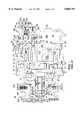
- a scroll type compressorincludes a housing 10 having a front end plate 11 and a cup-shaped casing 12.
- Front end plate 11has an opening 111 through which drive shaft 13 passes.
- An annular projection 112extends from a rear surface of front end plate 11.
- Annular projection 112faces cup-shaped casing 12 and is concentric with opening 111.
- Annular projection 112extends into cup-shaped casing 12, such that an outer peripheral surface of annular projection 112 is adjacent an inner wall surface of opening 121 of cup-shaped casing 12. Opening 121 of cup-shaped casing 12 is thus covered by front end plate 11.
- An O-ring 14is placed between the outer peripheral surface of annular projection 112 and inner wall of opening 121 of cup-shaped casing 12 to seal the mating surfaces thereof.
- a partition wall 122longitudinally projects from the inner end surface of the rear end portion of cup-shaped casing 112 to divide rear chamber 28 into a discharge chamber 281 and an intermediate chamber 282.
- the forward surface of partition wall 122contacts the rear end surface of circular end plate 211.
- Orbiting scroll 22, which is located in front chamber 27,includes a circular end plate 221 and a spiral element 222 extending from a rear end surface of circular end plate 221.
- Spiral element 222 of orbiting scroll 22 and spiral element 212 of fixed scroll 21interfit at an angular offset of approximately 180 degrees and a predetermined radial offset to form a plurality of sealed spaces between spiral element 212 and 222.
- Orbiting scroll 22is rotatably supported by bushing 23, which is eccentrically connected to the inner end of disk-shaped portion 131 through a radial needle bearing 30. While orbiting scroll 22 orbits, rotation thereof is prevented by rotation preventing/thrust bearing mechanism 24, which is placed between front end plate 11 and circular end plate 221 of orbiting scroll 22.
- Compressor housing 10is provided with an inlet port 31 and outlet port 32 for connecting the compressor to an external refrigeration circuit (not shown). Refrigeration fluid from the external refrigeration circuit is introduced into suction chamber 271 through inlet port 31, and flows into the plurality of sealed spaces formed between spiral elements 212 and 222.
- the plurality of sealed spaces between the spiral elementssequentially open and close during the orbital motion of orbiting scroll 22. When these spaces are open, fluid to be compressed flows into these spaces. When the spaces are closed, no additional fluid flows into these spaces and compression begins.
- the outer terminal end of spiral elements 212 and 222terminate at a final involute angle, the location of the spaces is directly related to the final involute angle.
- refrigeration fluid in the sealed spaceis moved radially inwardly and is compressed by the orbital motion of orbiting scroll 22.
- Compressed refrigeration fluid at a central sealed spaceis discharged to discharge chamber 281 past valve plate 231 through discharge port 213 formed at the center of circular end plate 211.
- a pair of holesare formed in circular end plate 211 of fixed scroll 21 and are symmetrically placed so that an axial end surface of spiral elements 222 of orbiting scroll 22 simultaneously crosses over both holes.
- Hole 214(and the other holes not shown) provide fluid communication between the plurality of sealed spaces and intermediate pressure chamber 282.
- Hole 214is placed at a position defined by involute angle ( ⁇ ) (not shown) and opens along the inner side wall of spiral element 212.
- the other holeis placed at a position defined by involute angle ( ⁇ ) (not shown) and opens along a radially outside wall of spiral element 212.
- valve plate 341A pair of valve plates (only one valve plate is shown as valve plate 341) are attached by fasteners (not shown) to the end surface of circular end plate 211 opposite hole 214 and the other holes, respectively.
- Valve plate 341 and the other valve plate (not shown)are made of a material having spring constant which biases valve plates 341 against the openings of holes 214.
- valve retainerprevents excessive bending of valve plates 341.
- Circular end plate 211 of fixed scroll 21also has communicating channel 29 formed therein and located at a radially outer side portion of the terminal end of spiral element 212. Communicating channel 29 provides fluid communication between suction chamber 271 and intermediate pressure chamber 282.
- a control mechanism 36controls fluid communication between suction chamber 271 and intermediate pressure chamber 282.
- Control mechanism 36comprises a first valve element 37 having a cylinder 371 and a piston 372 slidably disposed within cylinder 371.
- Control mechanism 36also comprises a second valve element 38.
- a first opening 373, which opens to intermediate pressure chamber 282,is formed through a side wall of cylinder 371.
- a second opening 374, which opens to communicating channel 29,is formed at a bottom portion of cylinder 371.
- a sealing ring member 61is disposed on an inner surface 122a of partition wall 122.
- An axial annular projection 376outwardly projects from the bottom of piston 372.
- a plurality of communicating holes 377are formed in axial annular projection 376 to provide fluid communication between the interior of piston 372 and space 60.
- a bias spring 39is disposed between a rear end surface of circular end plate 211 and the bottom portion of piston 372 to urge piston 372 rightwardly in FIG. 1.
- control mechanism 36The operation of control mechanism 36 is as follows. When the compressor is in operation, and is driven in a condition in which the suction pressure is relatively high (i.e., the heat load is relatively great), the pressure of communicating channel 29 is greater than that of predetermined operation pressure of bellows 381, and bellows 381 contracts. As a result needle ball-type valve 382 moves forward to block valve seat 385. Therefore, discharge gas pressure led into cylinder 371 through orifice tube 63 fills hollow portion 378 to urge piston 372 toward circular end plate 211 against the restoring force of bias spring 39. If the heat load is high enough, piston 372 blocks first and second openings 373, 374, thereby preventing communication between suction chamber 271 and intermediate pressure chamber 282.
- FIG. 3is an enlarged partial sectional view of a control valve mechanism of a scroll type refrigerant compressor shown in FIG. 2.
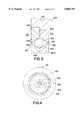
- Disk plate 423which is disposed in cylindrical depression 240, includes conical hole 424 extending from the first end surface 426 thereof and small cylindrical hole 425 extending from second end surface 427 thereof. Disk plate 423 is preferably made of the same material as that of orbiting scroll 22. Disk plate 423 is forcibly inserted into cylindrical depression 240 so that open end of conical hole 424 of disk plate 423 substantially corresponds with open end of conical hole 250. Ball 422 is enclosed between conical hole 250 and conical hole 424.
- Cylindrical depression 240, conical hole 250, small cylindrical hole 251, conical hole 424, small cylindrical hole 425 and ball 422collectively form bypass hole 420.
- the circumference portion 420a of bypass hole 420which is defined by the mating surfaces of conical hole 250 and conical hole 424, is preferably greater than the diameter of ball 422 so that ball 422 freely moves within bypass hole 420.
- the changing point of the compressor capacitywhich relates to the rotating speed of the compressor and the heat load, can be altered by changing the angle of conical holes 250, 424. In this embodiment, when the rotating speed of the compressor decreases, ball 422 is subjected to a small centrifugal force in the radial direction. Further, the differential pressure, which is caused between fluid pocket 272 and cavity 421, urges ball 422 toward cavity 421 to close bypass hole 420.
- End plate 221 of orbiting scroll 22is provided with a plurality of bypass holes 420, 520 and 620 formed between spiral elements 212 and 222.
- Fluid pockets 272communicate with cavity 421, which is defined by the axial end of bushing 23 and end plate 221. Cavity 421 communicates with suction chamber 271.
- End plate 221includes cylindrical depression 241 and preferably has a plurality of small cylindrical holes 251, 253 and 255 extending from one end of conical holes 250, 252 and 254 to fluid pockets 272.
- Disk plate 523includes a plurality of conical holes 524, 526 and 528 extending from first end surface 530 thereof and a plurality of small cylindrical holes 525, 527 and 529 extending from second end surface 531 thereof.
- Disk plate 523is preferably made of the same material as that of orbiting scroll 22. Disk plate 523 is forcibly inserted into cylindrical depression 241 so that the open ends of conical holes 524, 526 and 528 substantially correspond with open ends of conical holes 250, 252 and 254. Balls 422 are enclosed between conical holes 250, 252 and 254 and conical holes 524, 526 and 528. Small cylindrical holes 525, 527 and 529, small cylindrical holes 251, 253 and 255 and balls 422 collectively form bypass holes 420, 520 and 620 and a valve mechanism. Substantially the same effects and advantages as those in the first embodiment are realized in the second embodiment.
Landscapes
- Engineering & Computer Science (AREA)
- Mechanical Engineering (AREA)
- General Engineering & Computer Science (AREA)
- Rotary Pumps (AREA)
- Applications Or Details Of Rotary Compressors (AREA)
Abstract
Description
Claims (13)
Applications Claiming Priority (2)
| Application Number | Priority Date | Filing Date | Title |
|---|---|---|---|
| JP18351595AJP3549631B2 (en) | 1995-06-26 | 1995-06-26 | Variable capacity scroll compressor |
| JP7-183515 | 1995-06-26 |
Publications (1)
| Publication Number | Publication Date |
|---|---|
| US5860791Atrue US5860791A (en) | 1999-01-19 |
Family
ID=16137199
Family Applications (1)
| Application Number | Title | Priority Date | Filing Date |
|---|---|---|---|
| US08/670,062Expired - LifetimeUS5860791A (en) | 1995-06-26 | 1996-06-25 | Scroll compressor with end-plate valve having a conical passage and a free sphere |
Country Status (4)
| Country | Link |
|---|---|
| US (1) | US5860791A (en) |
| EP (1) | EP0754862B1 (en) |
| JP (1) | JP3549631B2 (en) |
| DE (1) | DE69608362T2 (en) |
Cited By (8)
| Publication number | Priority date | Publication date | Assignee | Title |
|---|---|---|---|---|
| US6053714A (en)* | 1997-12-12 | 2000-04-25 | Scroll Technologies, Inc. | Scroll compressor with slider block |
| US6095765A (en)* | 1998-03-05 | 2000-08-01 | Carrier Corporation | Combined pressure ratio and pressure differential relief valve |
| US6176685B1 (en)* | 1998-01-28 | 2001-01-23 | Sanden Corporation | Scroll compressor in which communication is controlled between adjacent compression spaces |
| US6244834B1 (en)* | 1998-01-30 | 2001-06-12 | Denso Corporation | Variable capacity-type scroll compressor |
| US6379131B1 (en) | 1999-03-04 | 2002-04-30 | Sanden Corporation | Scroll type compressor |
| US20050150207A1 (en)* | 2003-12-10 | 2005-07-14 | Christensen Donald J. | Fluidic diverter valve with a variable valve-bore clearance |
| US20060263229A1 (en)* | 2005-05-18 | 2006-11-23 | White Hydraulics Inc | Balancing plate--shuttle ball |
| US20090223244A1 (en)* | 2008-03-06 | 2009-09-10 | Yoshio Kimoto | Swash plate type compressor |
Families Citing this family (1)
| Publication number | Priority date | Publication date | Assignee | Title |
|---|---|---|---|---|
| JP5396235B2 (en)* | 2009-10-26 | 2014-01-22 | 日立アプライアンス株式会社 | Scroll compressor |
Citations (39)
| Publication number | Priority date | Publication date | Assignee | Title |
|---|---|---|---|---|
| US2350537A (en)* | 1941-01-16 | 1944-06-06 | Westinghouse Electric & Mfg Co | Fluid translating apparatus |
| US3253607A (en)* | 1964-06-10 | 1966-05-31 | Trw Inc | Combination pump and flow regulator |
| US3367562A (en)* | 1966-06-23 | 1968-02-06 | Atlas Copco Ab | Means for unloading and controlling compressor units |
| US3759057A (en)* | 1972-01-10 | 1973-09-18 | Westinghouse Electric Corp | Room air conditioner having compressor with variable capacity and control therefor |
| DE2338808A1 (en)* | 1972-08-01 | 1974-02-14 | Medizin Und Labortechnik Leipi | DEVICE FOR REDUCTION OR AVOIDING INTERNAL COMPRESSIONS IN MULTI-STAGE SCREW PUMPS, IN PARTICULAR EVOLVENT PUMPS |
| US3953153A (en)* | 1974-05-17 | 1976-04-27 | Sundstrand Corporation | Multiple displacement pump system and method |
| JPS5535156A (en)* | 1978-09-04 | 1980-03-12 | Sanden Corp | Volume type fluid compressor |
| EP0009350A1 (en)* | 1978-09-04 | 1980-04-02 | Sanden Corporation | Scroll-type fluid compressor units |
| US4382370A (en)* | 1980-10-31 | 1983-05-10 | Hitachi, Ltd. | Refrigerating system using scroll type compressor |
| US4383805A (en)* | 1980-11-03 | 1983-05-17 | The Trane Company | Gas compressor of the scroll type having delayed suction closing capacity modulation |
| JPS58167893A (en)* | 1982-03-29 | 1983-10-04 | Toyoda Autom Loom Works Ltd | Volumetric fluid compressing device |
| US4431388A (en)* | 1982-03-05 | 1984-02-14 | The Trane Company | Controlled suction unloading in a scroll compressor |
| US4432708A (en)* | 1980-07-01 | 1984-02-21 | Sanden Corporation | Scroll type fluid displacement apparatus with pressure communicating passage between pockets |
| US4459817A (en)* | 1980-12-16 | 1984-07-17 | Nippon Soken, Inc. | Rotary compressor |
| EP0113786A1 (en)* | 1982-12-15 | 1984-07-25 | Sanden Corporation | Scroll type compressor with displacement adjusting mechanism |
| US4468178A (en)* | 1981-03-09 | 1984-08-28 | Sanden Corporation | Scroll type compressor with displacement adjusting mechanism |
| US4496296A (en)* | 1982-01-13 | 1985-01-29 | Hitachi, Ltd. | Device for pressing orbiting scroll member in scroll type fluid machine |
| US4498848A (en)* | 1982-03-30 | 1985-02-12 | Daimler-Benz Aktiengesellschaft | Reciprocating piston air compressor |
| US4505651A (en)* | 1982-08-07 | 1985-03-19 | Sanden Corporation | Scroll type compressor with displacement adjusting mechanism |
| JPS60101295A (en)* | 1983-11-08 | 1985-06-05 | Sanden Corp | Compression capacity varying type scroll compressor |
| US4557670A (en)* | 1982-03-09 | 1985-12-10 | Nippon Soken, Inc. | Compressor |
| US4566863A (en)* | 1983-09-16 | 1986-01-28 | Kabushiki Kaisha Toyoda Jidoshokki Seisakusho | Rotary compressor operable under a partial delivery capacity |
| JPS6291680A (en)* | 1985-10-17 | 1987-04-27 | Sanden Corp | Variable delivery type scroll compressor |
| US4673340A (en)* | 1984-11-09 | 1987-06-16 | Sanden Corporation | Variable capacity scroll type fluid compressor |
| US4717314A (en)* | 1985-08-10 | 1988-01-05 | Sanden Corporation | Scroll compressor with control device for variable displacement mechanism |
| US4744733A (en)* | 1985-06-18 | 1988-05-17 | Sanden Corporation | Scroll type compressor with variable displacement mechanism |
| JPS63212789A (en)* | 1987-02-28 | 1988-09-05 | Sanden Corp | Variable capacity type scroll compressor |
| DE3804418A1 (en)* | 1987-03-26 | 1988-10-13 | Mitsubishi Heavy Ind Ltd | CAPACITY CONTROL DEVICE FOR SPIRAL HOUSING COMPRESSORS |
| EP0297840A2 (en)* | 1987-06-30 | 1989-01-04 | Sanden Corporation | Scroll type compressor with variable displacement mechanism |
| JPH01106990A (en)* | 1987-10-19 | 1989-04-24 | Daikin Ind Ltd | Capacity controlling mechanism for scroll type compressor |
| US4846633A (en)* | 1986-11-27 | 1989-07-11 | Mitsubishi Denki Kabushiki Kaisha | Variable-capacity scroll-type compressor |
| JPH01318777A (en)* | 1988-06-20 | 1989-12-25 | Daikin Ind Ltd | Variable capacity type scroll compressor |
| US4940395A (en)* | 1987-12-08 | 1990-07-10 | Sanden Corporation | Scroll type compressor with variable displacement mechanism |
| JPH0318678A (en)* | 1989-06-16 | 1991-01-28 | Mitsubishi Electric Corp | Scroll compressor |
| JPH0392592A (en)* | 1989-09-05 | 1991-04-17 | Daikin Ind Ltd | Scroll type compressor |
| EP0513827A1 (en)* | 1991-05-15 | 1992-11-19 | Sanden Corporation | Scroll type fluid displacement apparatus having a capacity control mechanism |
| US5240388A (en)* | 1991-03-15 | 1993-08-31 | Sanden Corporation | Scroll type compressor with variable displacement mechanism |
| US5336058A (en)* | 1992-02-18 | 1994-08-09 | Sanden Corporation | Scroll-type compressor with variable displacement mechanism |
| US5562426A (en)* | 1994-06-03 | 1996-10-08 | Kabushiki Kaisha Toyoda Jidoshokki Seisakusho | Scroll type refrigerant compressor |
- 1995
- 1995-06-26JPJP18351595Apatent/JP3549631B2/ennot_activeExpired - Lifetime
- 1996
- 1996-06-21EPEP96304605Apatent/EP0754862B1/ennot_activeExpired - Lifetime
- 1996-06-21DEDE69608362Tpatent/DE69608362T2/ennot_activeExpired - Lifetime
- 1996-06-25USUS08/670,062patent/US5860791A/ennot_activeExpired - Lifetime
Patent Citations (44)
| Publication number | Priority date | Publication date | Assignee | Title |
|---|---|---|---|---|
| US2350537A (en)* | 1941-01-16 | 1944-06-06 | Westinghouse Electric & Mfg Co | Fluid translating apparatus |
| US3253607A (en)* | 1964-06-10 | 1966-05-31 | Trw Inc | Combination pump and flow regulator |
| US3367562A (en)* | 1966-06-23 | 1968-02-06 | Atlas Copco Ab | Means for unloading and controlling compressor units |
| US3759057A (en)* | 1972-01-10 | 1973-09-18 | Westinghouse Electric Corp | Room air conditioner having compressor with variable capacity and control therefor |
| DE2338808A1 (en)* | 1972-08-01 | 1974-02-14 | Medizin Und Labortechnik Leipi | DEVICE FOR REDUCTION OR AVOIDING INTERNAL COMPRESSIONS IN MULTI-STAGE SCREW PUMPS, IN PARTICULAR EVOLVENT PUMPS |
| US3953153A (en)* | 1974-05-17 | 1976-04-27 | Sundstrand Corporation | Multiple displacement pump system and method |
| JPS5535156A (en)* | 1978-09-04 | 1980-03-12 | Sanden Corp | Volume type fluid compressor |
| EP0009350A1 (en)* | 1978-09-04 | 1980-04-02 | Sanden Corporation | Scroll-type fluid compressor units |
| US4432708A (en)* | 1980-07-01 | 1984-02-21 | Sanden Corporation | Scroll type fluid displacement apparatus with pressure communicating passage between pockets |
| US4382370A (en)* | 1980-10-31 | 1983-05-10 | Hitachi, Ltd. | Refrigerating system using scroll type compressor |
| US4383805A (en)* | 1980-11-03 | 1983-05-17 | The Trane Company | Gas compressor of the scroll type having delayed suction closing capacity modulation |
| US4459817A (en)* | 1980-12-16 | 1984-07-17 | Nippon Soken, Inc. | Rotary compressor |
| US4468178A (en)* | 1981-03-09 | 1984-08-28 | Sanden Corporation | Scroll type compressor with displacement adjusting mechanism |
| US4496296A (en)* | 1982-01-13 | 1985-01-29 | Hitachi, Ltd. | Device for pressing orbiting scroll member in scroll type fluid machine |
| US4431388A (en)* | 1982-03-05 | 1984-02-14 | The Trane Company | Controlled suction unloading in a scroll compressor |
| US4557670A (en)* | 1982-03-09 | 1985-12-10 | Nippon Soken, Inc. | Compressor |
| JPS58167893A (en)* | 1982-03-29 | 1983-10-04 | Toyoda Autom Loom Works Ltd | Volumetric fluid compressing device |
| US4498848A (en)* | 1982-03-30 | 1985-02-12 | Daimler-Benz Aktiengesellschaft | Reciprocating piston air compressor |
| US4505651A (en)* | 1982-08-07 | 1985-03-19 | Sanden Corporation | Scroll type compressor with displacement adjusting mechanism |
| EP0113786A1 (en)* | 1982-12-15 | 1984-07-25 | Sanden Corporation | Scroll type compressor with displacement adjusting mechanism |
| US4566863A (en)* | 1983-09-16 | 1986-01-28 | Kabushiki Kaisha Toyoda Jidoshokki Seisakusho | Rotary compressor operable under a partial delivery capacity |
| EP0144169A2 (en)* | 1983-11-08 | 1985-06-12 | Sanden Corporation | Scroll type compressor with displacement adjusting mechanism |
| JPS60101295A (en)* | 1983-11-08 | 1985-06-05 | Sanden Corp | Compression capacity varying type scroll compressor |
| US4642034A (en)* | 1983-11-08 | 1987-02-10 | Sanden Corporation | Scroll type compressor with displacement adjusting mechanism |
| US4673340A (en)* | 1984-11-09 | 1987-06-16 | Sanden Corporation | Variable capacity scroll type fluid compressor |
| USRE34148E (en)* | 1985-06-18 | 1992-12-22 | Sanden Corporation | Scroll type compressor with variable displacement mechanism |
| US4744733A (en)* | 1985-06-18 | 1988-05-17 | Sanden Corporation | Scroll type compressor with variable displacement mechanism |
| US4717314A (en)* | 1985-08-10 | 1988-01-05 | Sanden Corporation | Scroll compressor with control device for variable displacement mechanism |
| JPS6291680A (en)* | 1985-10-17 | 1987-04-27 | Sanden Corp | Variable delivery type scroll compressor |
| US4846633A (en)* | 1986-11-27 | 1989-07-11 | Mitsubishi Denki Kabushiki Kaisha | Variable-capacity scroll-type compressor |
| JPS63212789A (en)* | 1987-02-28 | 1988-09-05 | Sanden Corp | Variable capacity type scroll compressor |
| DE3804418A1 (en)* | 1987-03-26 | 1988-10-13 | Mitsubishi Heavy Ind Ltd | CAPACITY CONTROL DEVICE FOR SPIRAL HOUSING COMPRESSORS |
| EP0297840A2 (en)* | 1987-06-30 | 1989-01-04 | Sanden Corporation | Scroll type compressor with variable displacement mechanism |
| US4904164A (en)* | 1987-06-30 | 1990-02-27 | Sanden Corporation | Scroll type compressor with variable displacement mechanism |
| JPH01106990A (en)* | 1987-10-19 | 1989-04-24 | Daikin Ind Ltd | Capacity controlling mechanism for scroll type compressor |
| US4940395A (en)* | 1987-12-08 | 1990-07-10 | Sanden Corporation | Scroll type compressor with variable displacement mechanism |
| JPH01318777A (en)* | 1988-06-20 | 1989-12-25 | Daikin Ind Ltd | Variable capacity type scroll compressor |
| JPH0318678A (en)* | 1989-06-16 | 1991-01-28 | Mitsubishi Electric Corp | Scroll compressor |
| JPH0392592A (en)* | 1989-09-05 | 1991-04-17 | Daikin Ind Ltd | Scroll type compressor |
| US5240388A (en)* | 1991-03-15 | 1993-08-31 | Sanden Corporation | Scroll type compressor with variable displacement mechanism |
| EP0513827A1 (en)* | 1991-05-15 | 1992-11-19 | Sanden Corporation | Scroll type fluid displacement apparatus having a capacity control mechanism |
| US5362211A (en)* | 1991-05-15 | 1994-11-08 | Sanden Corporation | Scroll type fluid displacement apparatus having a capacity control mechanism |
| US5336058A (en)* | 1992-02-18 | 1994-08-09 | Sanden Corporation | Scroll-type compressor with variable displacement mechanism |
| US5562426A (en)* | 1994-06-03 | 1996-10-08 | Kabushiki Kaisha Toyoda Jidoshokki Seisakusho | Scroll type refrigerant compressor |
Non-Patent Citations (1)
| Title |
|---|
| Patent Abstracts of Japan, vol. 15, No. 138, Apr. 1991.* |
Cited By (14)
| Publication number | Priority date | Publication date | Assignee | Title |
|---|---|---|---|---|
| US6053714A (en)* | 1997-12-12 | 2000-04-25 | Scroll Technologies, Inc. | Scroll compressor with slider block |
| US6267573B1 (en) | 1997-12-12 | 2001-07-31 | Scroll Technologies | Slider block hard stop |
| US6176685B1 (en)* | 1998-01-28 | 2001-01-23 | Sanden Corporation | Scroll compressor in which communication is controlled between adjacent compression spaces |
| US6244834B1 (en)* | 1998-01-30 | 2001-06-12 | Denso Corporation | Variable capacity-type scroll compressor |
| US6095765A (en)* | 1998-03-05 | 2000-08-01 | Carrier Corporation | Combined pressure ratio and pressure differential relief valve |
| US6379131B1 (en) | 1999-03-04 | 2002-04-30 | Sanden Corporation | Scroll type compressor |
| US20050150207A1 (en)* | 2003-12-10 | 2005-07-14 | Christensen Donald J. | Fluidic diverter valve with a variable valve-bore clearance |
| US7051512B2 (en) | 2003-12-10 | 2006-05-30 | Honeywell International, Inc. | Fluidic diverter valve with a variable valve-bore clearance |
| US20060263229A1 (en)* | 2005-05-18 | 2006-11-23 | White Hydraulics Inc | Balancing plate--shuttle ball |
| WO2006125010A3 (en)* | 2005-05-18 | 2007-07-05 | White Drive Products Inc | Balancing plate-shuttle ball |
| US7322808B2 (en)* | 2005-05-18 | 2008-01-29 | White Drive Products, Inc. | Balancing plate—shuttle ball |
| CN101198766B (en)* | 2005-05-18 | 2010-08-18 | 怀特驱动产品有限公司 | balance cricket |
| RU2401386C2 (en)* | 2005-05-18 | 2010-10-10 | Уайт Драйв Продактс, Инк. | Hydraulic device |
| US20090223244A1 (en)* | 2008-03-06 | 2009-09-10 | Yoshio Kimoto | Swash plate type compressor |
Also Published As
| Publication number | Publication date |
|---|---|
| EP0754862B1 (en) | 2000-05-17 |
| EP0754862A1 (en) | 1997-01-22 |
| JPH0914164A (en) | 1997-01-14 |
| JP3549631B2 (en) | 2004-08-04 |
| DE69608362T2 (en) | 2000-09-07 |
| DE69608362D1 (en) | 2000-06-21 |
Similar Documents
| Publication | Publication Date | Title |
|---|---|---|
| US4940395A (en) | Scroll type compressor with variable displacement mechanism | |
| US4744733A (en) | Scroll type compressor with variable displacement mechanism | |
| US4642034A (en) | Scroll type compressor with displacement adjusting mechanism | |
| EP0211672B1 (en) | Scroll type compressor with variable displacement mechanism | |
| US4505651A (en) | Scroll type compressor with displacement adjusting mechanism | |
| US4468178A (en) | Scroll type compressor with displacement adjusting mechanism | |
| US4904164A (en) | Scroll type compressor with variable displacement mechanism | |
| AU661308B2 (en) | Scroll type fluid displacement apparatus having a capacity control mechanism | |
| US4456435A (en) | Scroll type fluid displacement apparatus | |
| US4673340A (en) | Variable capacity scroll type fluid compressor | |
| EP0256624A2 (en) | Variable capacity vane compressor | |
| EP0503629B1 (en) | Scroll type compressor with variable displacement mechanism | |
| CN101761478A (en) | Scroll compressor | |
| US4818189A (en) | Variable capacity vane compressor | |
| US5860791A (en) | Scroll compressor with end-plate valve having a conical passage and a free sphere | |
| EP0113786A1 (en) | Scroll type compressor with displacement adjusting mechanism | |
| EP0715080B1 (en) | Fluid displacement apparatus with variable displacement mechanism | |
| CA2046245C (en) | Scroll type compressor with variable displacement mechanism | |
| GB2146075A (en) | Scroll type compressor with displacement adjusting mechanism | |
| JPH07259765A (en) | Compressor | |
| JPH0229879B2 (en) | KAHENYORYOATSUSHUKUKI |
Legal Events
| Date | Code | Title | Description |
|---|---|---|---|
| AS | Assignment | Owner name:SANDEN CORPORATION, JAPAN Free format text:ASSIGNMENT OF ASSIGNORS INTEREST;ASSIGNOR:TOSHIYUKI, KIKUCHI;REEL/FRAME:008129/0615 Effective date:19960828 | |
| STCF | Information on status: patent grant | Free format text:PATENTED CASE | |
| FPAY | Fee payment | Year of fee payment:4 | |
| REMI | Maintenance fee reminder mailed | ||
| FPAY | Fee payment | Year of fee payment:8 | |
| FPAY | Fee payment | Year of fee payment:12 | |
| AS | Assignment | Owner name:SANDEN HOLDINGS CORPORATION, JAPAN Free format text:CHANGE OF NAME;ASSIGNOR:SANDEN CORPORATION;REEL/FRAME:038489/0677 Effective date:20150402 | |
| AS | Assignment | Owner name:SANDEN HOLDINGS CORPORATION, JAPAN Free format text:CORRECTIVE ASSIGNMENT TO CORRECT THE PROPERTY NUMBERS PREVIOUSLY RECORDED AT REEL: 038489 FRAME: 0677. ASSIGNOR(S) HEREBY CONFIRMS THE ASSIGNMENT;ASSIGNOR:SANDEN CORPORATION;REEL/FRAME:047208/0635 Effective date:20150402 | |
| AS | Assignment | Owner name:SANDEN HOLDINGS CORPORATION, JAPAN Free format text:CORRECTIVE ASSIGNMENT TO CORRECT THE TYPOGRAPHICAL ERRORS IN PATENT NOS. 6129293, 7574813, 8238525, 8083454, D545888, D467946, D573242, D487173, AND REMOVE 8750534 PREVIOUSLY RECORDED ON REEL 047208 FRAME 0635. ASSIGNOR(S) HEREBY CONFIRMS THE CHANGE OF NAME;ASSIGNOR:SANDEN CORPORATION;REEL/FRAME:053545/0524 Effective date:20150402 |