US5860648A - Golfing game including object sensing and validation - Google Patents
Golfing game including object sensing and validationDownload PDFInfo
- Publication number
- US5860648A US5860648AUS08/697,961US69796196AUS5860648AUS 5860648 AUS5860648 AUS 5860648AUS 69796196 AUS69796196 AUS 69796196AUS 5860648 AUS5860648 AUS 5860648A
- Authority
- US
- United States
- Prior art keywords
- target
- playing piece
- recited
- target field
- game
- Prior art date
- Legal status (The legal status is an assumption and is not a legal conclusion. Google has not performed a legal analysis and makes no representation as to the accuracy of the status listed.)
- Expired - Lifetime
Links
- 238000010200validation analysisMethods0.000titledescription12
- 230000007246mechanismEffects0.000claimsabstractdescription38
- 238000001454recorded imageMethods0.000claimsabstractdescription19
- 230000000284resting effectEffects0.000claimsabstractdescription9
- 230000000007visual effectEffects0.000claimsabstractdescription4
- 238000000034methodMethods0.000claimsdescription102
- 230000008569processEffects0.000claimsdescription55
- 230000015654memoryEffects0.000claimsdescription45
- 241001417527PempheridaeSpecies0.000claimsdescription16
- 238000013459approachMethods0.000claimsdescription5
- 230000005484gravityEffects0.000claimsdescription3
- 238000012545processingMethods0.000claimsdescription2
- 230000002708enhancing effectEffects0.000claims1
- 238000001514detection methodMethods0.000description14
- 230000006870functionEffects0.000description13
- 239000000872bufferSubstances0.000description12
- 238000010586diagramMethods0.000description12
- 230000000750progressive effectEffects0.000description11
- 238000004458analytical methodMethods0.000description10
- 238000012360testing methodMethods0.000description8
- 230000000903blocking effectEffects0.000description7
- 230000008859changeEffects0.000description6
- 230000009471actionEffects0.000description5
- 101000911753Homo sapiens Protein FAM107BProteins0.000description4
- 102100026983Protein FAM107BHuman genes0.000description4
- 230000008901benefitEffects0.000description4
- 238000010191image analysisMethods0.000description4
- 239000003086colorantSubstances0.000description3
- 239000000463materialSubstances0.000description3
- 244000025254Cannabis sativaSpecies0.000description2
- 230000004075alterationEffects0.000description2
- 238000003708edge detectionMethods0.000description2
- 230000007613environmental effectEffects0.000description2
- 238000012986modificationMethods0.000description2
- 230000004048modificationEffects0.000description2
- 230000002441reversible effectEffects0.000description2
- 238000005096rolling processMethods0.000description2
- 238000005070samplingMethods0.000description2
- 230000001360synchronised effectEffects0.000description2
- 241001482107Alosa sapidissimaSpecies0.000description1
- 241000209202Bromus secalinusSpecies0.000description1
- VVQNEPGJFQJSBK-UHFFFAOYSA-NMethyl methacrylateChemical compoundCOC(=O)C(C)=CVVQNEPGJFQJSBK-UHFFFAOYSA-N0.000description1
- 229920005372Plexiglas®Polymers0.000description1
- 230000003213activating effectEffects0.000description1
- 230000004913activationEffects0.000description1
- 230000015572biosynthetic processEffects0.000description1
- 238000007664blowingMethods0.000description1
- 230000003139buffering effectEffects0.000description1
- 238000004364calculation methodMethods0.000description1
- 238000004891communicationMethods0.000description1
- 239000002131composite materialSubstances0.000description1
- 230000003750conditioning effectEffects0.000description1
- 230000008878couplingEffects0.000description1
- 238000010168coupling processMethods0.000description1
- 238000005859coupling reactionMethods0.000description1
- 230000000694effectsEffects0.000description1
- 238000011156evaluationMethods0.000description1
- 239000000835fiberSubstances0.000description1
- 238000003197gene knockdownMethods0.000description1
- 239000011521glassSubstances0.000description1
- 230000001795light effectEffects0.000description1
- 238000012423maintenanceMethods0.000description1
- 238000005259measurementMethods0.000description1
- 239000002184metalSubstances0.000description1
- 230000003287optical effectEffects0.000description1
- 230000001151other effectEffects0.000description1
- 229920003023plasticPolymers0.000description1
- 238000003825pressingMethods0.000description1
- 230000004044responseEffects0.000description1
- 239000004065semiconductorSubstances0.000description1
- 230000003068static effectEffects0.000description1
- 201000009032substance abuseDiseases0.000description1
- 238000003786synthesis reactionMethods0.000description1
- 238000012546transferMethods0.000description1
- 239000002023woodSubstances0.000description1
Images


Classifications
- A—HUMAN NECESSITIES
- A63—SPORTS; GAMES; AMUSEMENTS
- A63B—APPARATUS FOR PHYSICAL TRAINING, GYMNASTICS, SWIMMING, CLIMBING, OR FENCING; BALL GAMES; TRAINING EQUIPMENT
- A63B67/00—Sporting games or accessories therefor, not provided for in groups A63B1/00 - A63B65/00
- A63B67/02—Special golf games, e.g. miniature golf ; Putting tracks therefor
- A—HUMAN NECESSITIES
- A63—SPORTS; GAMES; AMUSEMENTS
- A63F—CARD, BOARD, OR ROULETTE GAMES; INDOOR GAMES USING SMALL MOVING PLAYING BODIES; VIDEO GAMES; GAMES NOT OTHERWISE PROVIDED FOR
- A63F9/00—Games not otherwise provided for
- A63F9/02—Shooting or hurling games
- A63F9/0204—Targets therefor
- A63F9/0208—Targets therefor the projectile being connectable to the target, e.g. using hook and loop-type fastener, hooks
- G—PHYSICS
- G07—CHECKING-DEVICES
- G07F—COIN-FREED OR LIKE APPARATUS
- G07F17/00—Coin-freed apparatus for hiring articles; Coin-freed facilities or services
- G07F17/32—Coin-freed apparatus for hiring articles; Coin-freed facilities or services for games, toys, sports, or amusements
- G07F17/3286—Type of games
- G07F17/3297—Fairground games, e.g. Tivoli, coin pusher machines, cranes
- A—HUMAN NECESSITIES
- A63—SPORTS; GAMES; AMUSEMENTS
- A63B—APPARATUS FOR PHYSICAL TRAINING, GYMNASTICS, SWIMMING, CLIMBING, OR FENCING; BALL GAMES; TRAINING EQUIPMENT
- A63B24/00—Electric or electronic controls for exercising apparatus of preceding groups; Controlling or monitoring of exercises, sportive games, training or athletic performances
- A63B24/0021—Tracking a path or terminating locations
- A63B2024/0037—Tracking a path or terminating locations on a target surface or at impact on the ground
- A63B2024/0043—Systems for locating the point of impact on a specific surface
- A—HUMAN NECESSITIES
- A63—SPORTS; GAMES; AMUSEMENTS
- A63B—APPARATUS FOR PHYSICAL TRAINING, GYMNASTICS, SWIMMING, CLIMBING, OR FENCING; BALL GAMES; TRAINING EQUIPMENT
- A63B67/00—Sporting games or accessories therefor, not provided for in groups A63B1/00 - A63B65/00
- A63B67/06—Ring or disc tossing games, e.g. quoits; Throwing or tossing games, e.g. using balls; Games for manually rolling balls, e.g. marbles
- A63B2067/065—Ring or disc tossing games, e.g. quoits; Throwing or tossing games, e.g. using balls; Games for manually rolling balls, e.g. marbles used tossed devices of different sizes giving different degrees of difficulty for fitting in or over a target
- A—HUMAN NECESSITIES
- A63—SPORTS; GAMES; AMUSEMENTS
- A63B—APPARATUS FOR PHYSICAL TRAINING, GYMNASTICS, SWIMMING, CLIMBING, OR FENCING; BALL GAMES; TRAINING EQUIPMENT
- A63B63/00—Targets or goals for ball games
- A—HUMAN NECESSITIES
- A63—SPORTS; GAMES; AMUSEMENTS
- A63F—CARD, BOARD, OR ROULETTE GAMES; INDOOR GAMES USING SMALL MOVING PLAYING BODIES; VIDEO GAMES; GAMES NOT OTHERWISE PROVIDED FOR
- A63F7/00—Indoor games using small moving playing bodies, e.g. balls, discs or blocks
- A63F7/22—Accessories; Details
- A63F7/34—Other devices for handling the playing bodies, e.g. bonus ball return means
- A63F2007/345—Ball return mechanisms; Ball delivery
Definitions
- This inventionrelates to games normally played in an arcade environment, and more particularly to games that sense objects directed by a player to influence a game score.
- Games of many typesare played in arcade environments.
- One type of gameincludes object sensors for detecting objects directed by players at provided targets. Golfing games can make use of object detection to determine when a golf ball falls into a target hole.
- the object sensing games of the prior artwhile enjoyable, are limited when determining an identity of a directed object and the final resting position of the object.
- the prior art gamesare limited when determining a trajectory of a directed object. These prior art games tend to determine one of these characteristics, but not more.
- the prior art gamestend to assume that a directed object is a valid object and do not therefore determine the identity of an object or perform other validation procedures.
- the detection of ballstends to be limited to a sensor provided in the target hole or at a particular location on a putting green or field, which does not allow a reliable score or evaluation for balls that do not land in the hole.
- the present inventionprovides a golfing game having the ability to sense and validate objects.
- the gameprovides improved object detection and validation methods that reliably detect a directed playing piece and provide a score based on the position, identity, and/or trajectory of the playing piece.
- a game apparatus of the present inventionincludes a target field for receiving a playing piece directed by a player and a sensor for detecting a playing piece directed by a player.
- the sensordetermines a distance of the playing piece from a target on the target field after the playing piece engages the target field.
- a scoring mechanismprovides a game score based on a distance from the playing piece to the target.
- the sensordetermines a final position of the playing piece at rest after the playing piece engages the target field and the identity of the playing piece, and the score is based on the distance from the final position to the target.
- the point of closest approach of the playing piece to the targetcan be determined, and the score is based on the distance from the point of closest approach to the target.
- the target fieldincludes one or more individual targets, and the game score is based on the distance of the playing piece to one of the targets.
- a playercan select which target the playing piece is to be associated with, or it can be automatically selected.
- the game apparatusis used to provide a golf putting game.
- the individual targetscan be flat frames, positioned on the surface of the target field, which form an aperture having standard golf hole dimensions, or apertures provided in the target field.
- the playing pieceis a golf ball or similar object, and a player can direct multiple golf balls to the target field during a game.
- a removal mechanismremoves the balls from the target field when a game is over so that the player may retrieve the balls.
- Embodiments of removal mechanismsinclude a sweeper arm and a mechanism for tilting the target field such that the balls move off the target field.
- An award dispensercan be included to dispense an award to a player based on the game score.
- the game apparatusis preferably controlled by a digital computer.
- the sensorincludes a visual sensor for detecting the playing piece and determining a position(s) of the playing piece by detecting visible light.
- a disclosed sensing apparatusincludes a video camera and charge coupled device for recording one or more images of the target field and detecting a playing piece in the image.
- the sensoralso includes a digital processor for analyzing the image, determining the final position of the playing piece, and relaying the final position to the scoring mechanism.
- the digital processorscans a recorded image of the target field to detect pixels having an intensity associated with a playing piece.
- the image pixelsare also compared to a predetermined image, such as a mask pixel map, to determine the identity of the playing piece, i.e., if the playing piece is valid and not a false playing piece.
- a predetermined imagesuch as a mask pixel map
- imagesare taken and analyzed to determine if a playing piece has entered the target field. Multiple images are examined to determine whether the playing piece has come to rest. If pixels having a playing piece intensity correspond to pixels of the predetermined image within a threshold, then a valid playing piece has been detected. The distance between the detected playing piece and a designated target is then measured in the image.
- the digital processor and the sensorcan also analyze an object as it is moving toward or over the target field to determine if the object is a valid playing piece for the game apparatus, such as a golf ball.
- a moving objectis recorded in multiple successively-recorded images and the identity of the object in the images is verified.
- the trajectory of the moving objectcan also be analyzed in the images to determine if the object is a valid playing piece.
- a game score for the playing pieceonly when the identity and trajectory of the object is valid.
- An advantage of the present inventionis that the disclosed object sensing apparatus is accurate and dependable for validating directed objects as playing pieces or non-playing pieces.
- the sensing apparatuscan compensate for changing lighting conditions and other environmental conditions that can occur. The game can thus be operated with minimal operator supervision or maintenance.
- Another advantage of the present inventionis that the identity, trajectory, and position of directed playing pieces are reliably determined to provide an accurate score to a player of the game apparatus.
- the sensing apparatusis able to determine distances relative to playing pieces and targets with high accuracy, allowing a game score to be reliably based on playing piece positions. In a golfing game, these advantages allow the game to provide an accurate score to a player based on how closely the player's ball approached a target hole.
- FIG. 1is a perspective view of a golfing game apparatus of the present invention
- FIG. 2is a front cross-sectional view taken along line 1--1 of FIG. 1;
- FIGS. 3a and 3bare detail views of a ball dispenser for use with the present invention.
- FIG. 4is a perspective view of a first embodiment of a ball removal mechanism for use with the present invention.
- FIG. 5is a perspective view of a second embodiment of a ball removal mechanism for use with the present invention.
- FIG. 6is a block diagram of the control system for the game apparatus of the present invention.
- FIG. 7is a block diagram of the vision board controlling the sensing apparatus of the present invention.
- FIG. 8is a flow diagram illustrating the process of operating and playing the game apparatus of the present invention.
- FIG. 9is a diagrammatic illustration of an image of the target field recorded by the sensing apparatus.
- FIG. 10is a flow diagram illustrating the step of FIG. 8 of initializing and calibrating the game apparatus
- FIG. 11is a flow diagram illustrating the step of FIG. 8 of analyzing an image of a target field for balls during a game.
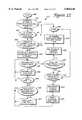
- FIG. 12is a flow diagram illustrating the step of FIG. 11 of finding a ball in an image and determining the distance between the ball and a target hole.
- FIG. 1is a perspective view of a game apparatus in accordance with the present invention.
- a golf ball or similar playing pieceis struck by a player using a golf club or other article and the ball moves into a target field.
- This embodimentis most appropriate for golf putting type games where players try to putt golf balls into target holes in a well-known fashion.
- Game apparatus 10includes a front panel section 102, a target section 104, and a ball field 106.
- Front panel section 102 and target section 104are included on or in a housing 102 which is provided at one end of playing field 106.
- Front panel section 102is positioned to be accessible to a player of game apparatus 10 before starting a game and includes a coin deposit panel 108, function buttons 110, target buttons 112, score displays 114, and speaker 120.
- An optional award dispenser 116can also be included.
- Coin deposit panel 108includes one or more coin deposit slots 118 and preferably accepts standard currency coins, game tokens that are often available in an arcade environment, or any other monetary input (e.g., paper bills, debit card, credit card, etc.). Coin deposit slots are well known to those skilled in the art.
- a cash boxcan be provided behind front panel section 102 to store deposited coins.
- Player and other function buttons 110are provided to allow a player to select various options concerning game play.
- the player buttonsselect the number of players playing a game.
- the game apparatus 10can readily provide a game in which two players compete to achieve the highest score, which is described in greater detail below.
- Other function buttons 110can select options including level of skill of player, resetting the game, ending the game when the player desires, a preferred award type, a progressive option, etc.
- Target buttons 112are function buttons that allow a player to designate a desired target for a directed ball. For example, in the described embodiment, three targets are provided at which the player may direct balls. Preferably, the player aims for one target at a time as selected by the appropriate button 112. Thus, for example, if a player wishes to direct his first ball to target hole #2, the player would push the button 112 corresponding to hole #2.
- the buttons 112are arranged similarly to the spatial arrangement of the targets in the target field 104.
- other variations of target selectioncan be used. For example, a player might select two of the targets with buttons 112 and direct playing pieces at either selected target. Or, a player might select the targets with buttons 112 in a specific order, and then direct playing pieces at targets in that same order.
- a targetcan be automatically selected by the control system of the game apparatus 10 according to a predetermined sequence or randomly.
- Score displays 114are used to display current scores of a game to the player(s).
- the game scoreis preferably based on the location of playing pieces 122 in target field 104 in relation to the targets in the target field. The determination of game score is described in greater detail with reference to FIG. 8.
- a progressive score displaycan be provided for displaying a progressive score.
- a progressive scoreseparate from the game score, can be accumulated and can be added to the game score if a progressive goal is achieved. For example, if a player manages to hit playing pieces in all three target holes, then the player can be considered to have achieved a progressive goal and the progressive score is added to the player's game score.
- the progressive scorecan, for example, be incremented with every coin inserted in coin slot 118 from previous and current games, automatically incremented over time, etc.
- Multiple game apparatuses 10can also be linked together to contribute to a collective progressive score, which can be rewarded to the first player of a linked game apparatus to achieve a progressive goal (multiple game apparatuses can also be linked to allow players of different game apparatuses to compete against each other directly during a game).
- Progressive goals, scores, and bonus apparatusesare described in greater detail in U.S. Pat. No. 5,292,127, by Kelly et al., entitled “Arcade Game”, and co-pending patent application Ser. No. 08/374,490, entitled “Ticket Redemption Game with Money-back Guarantee", filed Jan.
- Additional score displayscan be used to provide scores for multiple players of game apparatus 10 or provide other functions during game play.
- a number of awards, such as tickets,are preferably dispensed from award dispenser 116 based on the final game score displayed by display 114.
- score display 114can be positioned in other areas of game apparatus 10, such as on front panel 102.
- Award dispenser 116may optionally be included in game apparatus 10 to dispense tickets or other awards to the player based upon the result of a game. For example, tickets may be accumulated by a player and redeemed to win various prizes. Ticket dispensing mechanisms are well-known in the prior art. Other types of awards besides tickets may be dispensed by award dispenser 116. For example, sports cards or other trading cards, toy prizes, or even coins or currency can be dispensed. The awards can be stored in a storage area behind the front panel 102 or in housing 103.
- Speaker(s) 120emits sounds based on game actions and other game states and is controlled by the game controller system. The operation of the speakers will be discussed in greater detail subsequently.
- a player sensor 121can be included on front panel section 102 or other area of game apparatus 10.
- the player sensorcan detect if a player moves within a predetermined zone next to target field 104 on playing field 106. If a player is detected by sensor 121, the game is preferably over and the game score reset to zero. This prevents a player from trying to cheat at the game by extending an arm into or close to target field 128 to place playing pieces on targets, etc.
- a linecan be marked on playing field 106 to inform the player how close he or she can get to game target field 128 before activating sensor 121.
- the player sensor 121can be an electromagnetic sensor, such as a thermal sensor for detecting the presence of a human body, which is well-known to those skilled in the art. Other types of sensors, such as motion detectors, break beam sensors, etc., can also be used.
- a playing piece dispensercan be included in the game apparatus 10 to dispense playing pieces to a player.
- such playing piecesare golf balls, but other types of objects can also be used for playing pieces.
- the playing piece dispensercan be provided on front panel section 102 or other area of the game apparatus. An embodiment of a playing piece dispenser is described in parent patent application Ser. No. 08/408,618.
- Target section 104includes target field 128 and sensing apparatus 130.
- Target field 128is an area that is provided as a general target for playing pieces directed by a player of game apparatus 10.
- Housing 103covers target field 128 and a large opening is provided in one side of housing 103 to allow playing pieces to enter the target field.
- a transparent window cover 132made of a relatively rigid material such as glass, plexiglass, or plastic, is positioned to block most of the opening from entry of objects.
- a small opening 134having a height only slightly larger than playing pieces 122, is provided at the bottom of window cover 132 to allow playing pieces to move in and out of the target field 128 and to prevent players from accessing playing pieces that have entered the target field 128.
- the target field 128can be defined to extend further out onto playing field 106, or even include the entire length of the playing field 106 such that the sensing apparatus 130 (described below) detects playing pieces anywhere on the playing field.
- target field 128includes a number of target holes 136.
- target holegenerically refers to any type of target, such as an actual aperture in target field 128, frames 137 that form an aperture on the surface of the target field, markings or indicia on the target field, a cup on the target field, a standing target or hoop, or other types of targets.
- target holes 136are flat frames 137 with a central aperture 139 that is the size of a standard golf course hole. The frames have a small lip on their far edge to block a ball from rolling out of the central aperture 139 once the ball has entered the aperture.
- hole indicators 141such as flags, can be provided to label each target hole 136 so that the player can select a desired target with controls 512.
- other indicatorssuch as light sources (light bulbs, LED's, etc.) can be placed in or near target holes 136 to selectively indicate, draw attention to, or highlight particular targets to the player.
- the currently selected target holecan be highlighted by a light source so the player knows which target to aim for. This light source can later be deactivated and a light source in a different hole illuminated to highlight a different target later in the game.
- holes 136can be actual apertures provided in the surface of target field 128. Such an embodiment, however, may require the playing field 106 and target field 128 to be elevated above a base floor to provide the aperture, or the playing field to ramp up to a higher level of target field 128.
- target field 128can include other types of targets. For example, simple indicia, pictures, or images can be provided on target field 128 to portray a hole 136. Alternately, different types of targets can be provided, such as objects to knock down with a ball, ramps, electrical switches or solenoids, targets to be passed through with a directed ball, and other targets well known in other types of games such as pinball, croquet, and miniature golf.
- the target holes 136can be upright standing wire hoops which the player is to direct balls through using a wooden mallet.
- Other examples of targetsare described in parent patent application Ser. No. 08/408,618.
- Sensing apparatus 130is preferably positioned above target field 128 and senses any objects entering the target field.
- sensing apparatus 130is a camera, such as a digital video camera, that records images and continuously monitors target field 128 for any golf balls 122 or other playing pieces that are directed by the player. Other types of sensors can be used in alternate embodiments.
- the sensing apparatusdistinguishes the appropriate playing pieces used in the game and determines if any playing pieces have engaged targets such as holes 136.
- the sensing apparatus 130can also monitor the target field 128 when no game is played, so that ambient light conditions can be sensed, calibrations performed, and stray objects on target field 128 can be removed. Sensing apparatus 130 is described in greater detail with respect to FIG. 7 and 8.
- a removal mechanismis also preferably included to remove the playing pieces 122 from target field 128 to provide the player with the playing pieces when a game begins.
- the removal mechanismcan be used to clear the target field of playing pieces when a violation of the rules of the game is detected (e.g., the player cheats by placing a ball in a hole with his or her hand). Examples of removal mechanisms are described with respect to FIGS. 4 and 5.
- the front panel functions and displays, sensing apparatus 130, and other functions of the game apparatus 10are preferably controlled by a control system 144.
- This control systemis described in greater detail with respect to FIG. 6.
- the process of analyzing an image from sensing apparatus 130is described in greater detail with respect to FIG. 8.
- Playing field 106is provided in front of housing 103 to provide a simulated "putting green" surface on which players may putt golf balls or otherwise direct playing pieces.
- the playing fieldincludes a target end 138 and a player end 140.
- Playing field 106can be an artificial "grass” carpet or similar surface.
- playing field 106can be folded or rolled and thus conveniently stored when not in use, thus allowing the game apparatus 10 to occupy only the space necessary for housing 103 when the apparatus is not in use.
- One or more markers 142can be provided at or near the player end 140 of playing field 106 to direct the initial placement of golf balls 122 by the player before putting the ball.
- a line or other markingcan also be provided at target end 138 to show at which point on the playing filed 106 that directed balls will be sensed by sensing apparatus 130.
- the playing pieces 122 and any other necessary equipment to direct the playing piececan be manually obtained by the player (e.g., from an operator) before starting a game on game apparatus 10.
- playing piecescan be dispensed to the player from a dispenser included in game apparatus.
- golf ballscan be stored in a storage box or other receptacle and a predetermined number of the balls can be provided to the player after a coin is inserted, similarly to the dispenser described in parent application Ser. No. 08/408,618.
- a ball return mechanismcan return the balls to the storage receptacle after players have hit the balls onto target field 128 and/or on playing field 106.
- a ball return mechanism(such those described with reference to FIGS. 4 and 5) can sweep the balls into such a storage receptacle rather than moving the balls back onto playing field 106.
- FIG. 2is a cross-sectional front elevational view of the game apparatus 10 taken along line 1--1 of FIG. 1.
- Housing 103supports front panel 102 and sensing apparatus 130.
- Sensing apparatus 130is provided in the upper section of housing 103 to scan the target field 128 during a game and between games.
- sensing apparatus 130includes a video camera electrically coupled to a video board 144 that includes video circuitry including components shown in FIG. 7.
- the recorded view of sensing apparatus 130is approximately defined by dashed lines 146.
- sensing apparatus 130may record the ball in motion and/or at a final rest position (if the rest position is within the area of dashed lines 146).
- the sensing apparatus 130can also preferably be used to distinguish if the golf ball is a valid playing piece for use with the game by analyzing the shape, color/shade, and/or other characteristics of the ball.
- the trajectory of a ball as it moves into target field 128can also be analyzed to determine if the ball is a valid playing piece, as described with reference to FIG. 8.
- sensing apparatus 130can be angled to have a field of vision extending more toward the player of game apparatus 10 so that directed playing pieces can be detected before they reach target field 128 and, for example, sound, light, and other effects can be generated in response.
- the range of vision of sensing apparatus 130can be increased to include a greater area of target field 128 and playing field 106.
- Target holes 136preferably include frames 137 coupled to the target field 128. Once all of the balls that are allocated to a player during the game have been sensed in target field 128, a period of time elapses since the player began the game, or the game otherwise ends, the balls 122 are removed from the target field 128. This can be accomplished using a variety of methods and apparatuses. Preferred removal mechanisms is described below with respect to FIGS. 4 and 5.
- a ball dispenser 150is preferably provided in the upper section of housing 103 to dispense balls onto target field 128 when necessary. For example, a ball may be missing when a game is complete due to the ball getting lost, taken by a player, or some other reason. Sensing apparatus 130 can detect how many balls are present on target field 128 when a game is not currently in progress. If there are one or more balls missing, the control system of game apparatus 10 causes dispenser 150 to dispense enough balls to bring the number of balls on the target field to the proper number. A ball dispensed from dispenser 150 preferably falls straight down from the dispenser onto the target field 128. When a player starts a new game, the newly-dispensed ball(s) is moved with the other balls to the player by the removal mechanism described below.
- board 152can also be provided to include the components of the control system 144 as described with reference to FIG. 6.
- board 152is placed separately from the sensing apparatus control board 145 and controls operations such as game score displays, input from front panel buttons, sounds, lights, and other player feedback, etc.
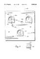
- FIGS. 3a and 3bare detailed elevational views of ball dispenser 150, where FIG. 3a is a front view and FIG. 3b is a side view.
- Extra balls 156are provided on a ramp 158 that is coupled to support sides 159.
- Ramp 158is inclined to cause the balls 156 to be forced by gravity toward a lower end 157 of the ramp.
- a stop mechanism 158is provided to block the balls 156 from rolling off the ramp.
- Stop mechanism 158includes rotating members 160, blocking members 162, and solenoid 164.
- Each rotating member 160is rotatably coupled to an associated support side (as shown in FIG. 3a) such that the rotating members are positioned on each side of the first ball 156 at the lower end of the ramp.
- Each of two blocking members 162is coupled to both rotating members 160 such that both rotating members and blocking members rotate in unison about axis A.
- Solenoid 164is rotatably coupled to one of the rotating members 160 and is physically grounded. The solenoid 164, when controlled by the control system of game apparatus 10, moves in the direction of arrow 166 to rotate rotating members 160 and members 162, as shown by arrow 168. This causes blocking members 162 to move to the position shown by dashed lines 170. With blocking members rotated, the first ball 156a is free to move down ramp 158 and fall down to target field 128 as indicated by arrow 172.
- solenoid 164moves back in the direction opposite to arrow 166 as caused by a spring 167, causing blocking members 162 and rotatable members 160 to move in the direction opposite to arrow 168 back to the starting position where the next ball 166 is blocked.
- the control systemthus can activate solenoid 164 as many times as the number of balls needed on target field 128.
- a greater number of balls than shown in FIG. 3bcan be provided in a storage receptacle or the like.
- a dispensersuch as dispenser 150 can also be used to dispense balls directly to the player when the player starts a game.
- a guidecan be coupled to the lower end of the ramp 158 to guide a predetermined number of balls 156 to the player at player end 140 of playing field 106.
- FIG. 4is a perspective view of a first embodiment of a removal mechanism 200 of game apparatus 10 for removing playing pieces from target field 128 to allow a player to retrieve the playing pieces.
- a sweeper arm 202preferably begins the game at the back side 203 of housing 103 of the game apparatus 10. After a player has directed balls 122 onto playing field 128 during a game and the game is over, the control system 144 instructs one or more actuators 204 in sweeper arm 202 to rotate wheels or an equivalent device to move sweeper arm 202 along guide rails 206 in a direction indicated by arrows 208. Since balls 122 are higher than frames 137 in most embodiments, the sweeper arm 202 is provided at an elevation above playing field 128 such that balls 122 are pushed toward target end 138 by the sweeper arm, but frames 137 are passed over by the sweeper arm.
- Balls 122are pushed out underneath transparent window 132 onto playing field 106 by the sweeper arm.
- balls 122need only be pushed a short distance, and a player of the game apparatus can simply retrieve the balls from the target end 138 of playing field 106 and place them in their starting position at player end 140.
- an additional guide or similar mechanismcan guide the balls to the player at the player end 140 of playing field 106.
- FIG. 5is a perspective view of a second embodiment 200' of a removal mechanism of game apparatus 10 for removing playing pieces from target field 128.
- Mechanism 200'includes a tilting section 220 of target field 128, and a pulley mechanism 222.
- Tilting section 220is preferably a rigid member such as a flat planar member of wood or metal, and includes the simulated grass material or carpet that extends from player end 140 to the target section 128.
- Tilting section 220can be tilted at a hinge 224 near the front of the housing 103.
- the rigid memberpreferably only extends a short distance past hinge 224 toward the player so that the remainder of playing field 106 is flexible and can be rolled or folded when the game apparatus is not in use.
- Pulley mechanism 222is coupled to an interior surface 226 of game housing 103 and is operative to lift one end of tilting section 220 such that balls 122 roll under the influence of gravity off of target section 128 and onto playing field 106.
- Pulley mechanism 222includes a main pulley 230, guide pulleys 232aand 232b, and an actuator 234.
- Main pulley 230is coupled to interior surface 226 and may rotate about axis F.
- Actuator 234has a shaft coupled to main pulley 230 and may rotate the pulley in either direction about axis F.
- Cable 236ais coupled to main pulley 230, routed around guide pulley 232a, and attached to a corner 238a of tilting section 220.
- Guide pulley 232acan rotate about axis G so that the cable 236b may be moved in either direction.
- cable 236bis coupled to main pulley 230, routed around guide pulley 232b, and attached to a corner 238b of tilting section 220.
- Guide pulley 232bcan rotate about axis H to allow the cable to move in either direction.
- Control system 144can activate actuator 234 after a player has directed all balls 122 and the game is over.
- Actuator 234rotates main pulley 222 so that cables 236a and 236b are wound around the main pulley, thus lifting the back edge of tilting section 220 so that section 220 rotates about the hinge 224.
- the cableis wound in this way until the tilting surface is tilted to a predetermined angle with the horizontal, such as 30 degrees, that is known to cause all the balls 122 to roll off the section 220 no matter where the balls are positioned on the target field. This position is shown as dotted lines 220a in FIG. 5.
- the control system 144then instructs the actuator 234 to rotate main pulley 230 in the opposite direction, thus lowering the cable and the edge of tilting section 220 until tilting section 220 lies in its original position used during game play.
- sensorscan be included on target field 128 or on pulleys or cable to detect when the actuator 234 should stop rotating main pulley 222 in either direction.
- limit switch 235can be placed to signal when cable 236a reaches a certain height, indicating to the control system to reverse or deactivate the motors.
- the tilting removal mechanismallows upright indicators or other structures can be placed on the target field without hindering the tilting removal mechanism.
- upright flagscan be placed on the target frames, or, in a croquet embodiment, upright hoops can be provided on target field 128 for ball 122 to pass through, etc.
- target field 128can be vibrated using an actuator or similar device, which causes the playing pieces to move in a desired direction off the target field.
- an air-blowing apparatuscan be provided to force the playing pieces in a desired direction off the target field using force derived from the directed air or other gas.
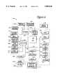
- FIG. 6is a block diagram of a control system 144 of game apparatus 10.
- the control systemfor example, can be implemented on one or more printed circuit boards 145 which can be coupled to game housing 103, behind front panel 102, etc.
- the components of control system 144include a microprocessor 240, RAM 242, ROM 244, a latch 248, DIP switches 250, drivers 252, buffers 254, latches 256, lamp drivers 258, sound chip 260, low pass filter 262, audio amplifier 264, and speakers 120.
- the microprocessor 240is preferably a standard microprocessor such as the 8-bit Intel 8031, which has the range of features adequate for the task, including eight data lines and sixteen address lines.
- the microprocessor 240is coupled to ROM 244 by a data/address/control bus 266.
- the ROM 244is preferably an erasable, programmable read-only memory (EPROM) that contains the start-up instructions and operating system for the microprocessor 240.
- EPROMerasable, programmable read-only memory
- Microprocessor 240is connected to RAM 242 by bus 266 to permit the use of RAM for scratch-pad memory. Methods for coupling ROM 244 and RAM 242 to the microprocessor 240 by bus 266 including enable, address, and control lines are well-known to those skilled in the art.
- the microprocessor 240is also coupled to a latch 248 by the bus 266.
- the switches 250 coupled to latch 248provide selectable functions that the operator of the game unit may change to his or her liking. These selectable functions can include the score achieved for landing a ball or other playing piece on a target, the time period that the game apparatus waits before assuming a game is over, etc. These factors can affect game play and the score achieved by a player. Other functions selectable by switches 250 include sound effects, the test mode, the type of game, and so on, depending on how many selectable functions are desired. Switches 250 can, for example, be implemented as DIP switches. Alternatively, the functions selected by switches 250 can be selected from another input device, such as a control panel of buttons, through software commands to the microprocessor 240, etc.
- the microprocessor 240is also coupled to drivers 252 and buffers 254.
- the buffers 254receive data from several switches and sensors, including test switch 268, coin slot switch 270, lift sensors 271, playing piece sensor 272, game buttons 510 and 512, and player sensor 121, if any of these features are used in a particular embodiment.
- Test switch 268can be a switch location in the interior of game apparatus 10 accessible to the operator which activates a test mode for the game apparatus 10 to determine if the game is operating correctly.
- Coin slot switch 270detects when a coin has been inserted into the coin slot 118 of the front panel 102.
- Limit sensors 210, 212, or 235detect the limits to the back and forward movement of sweeper arm 202 or tilting movement of target field 128, as described with reference to FIGS. 4 and 5.
- Playing piece sensor 272can be used to detect each playing piece as it is dispensed to the player (if a dispenser is included).
- Game controls 110 and 112are provided on front panel 102 and send signals to microprocessor 240 when pressed.
- Player sensor 121if included, sends a signal to microprocessor 240 when a person is sensed within its field of detection to cause the game to end and thus help prevent a player from cheating and getting too close to target field 128.
- a tilt switchcan be provided to sense whether the game apparatus is being moved or tipped by players, and to end the game if such tipping is detected.
- the tilt switchcan detect when players might try to illegally direct balls to high-scoring positions by tipping the game apparatus.
- Drivers 252activate output devices including award dispenser motor 272, pulley motor 234, and any other output devices.
- Award dispenser motor 272drives the award dispenser 116 in front panel 102 that provides tickets or other awards to a player.
- Removal motor(s) 204 or 234drives the sweep arm 204 or the pulley 230 of the target field 128 for removing playing pieces from the target field 128.
- Solenoid 164causes a ball to be dispensed onto target field 128 from dispenser 150.
- Other input/output devicessuch as a video display screen, playing piece dispenser motor, microphone, printer, network interface or modem, or the like, can also be provided in other embodiments.
- Vision board 276is preferably coupled directly to microprocessor 240 through a communication interface 278, such as a serial interface, and includes components for sensing apparatus 130 used to detect and verify tossed playing pieces on target field 128. Vision board 276 is described in greater detail with respect to FIG. 7.
- the microprocessor 240is also coupled to latches 256 which latch data for the lamp drivers 258.
- the lamp drivers 258supply power to the lamps 280, which include lights around the perimeter of game housing 103, front panel 102, target field 128, and other similar areas which can be highlighted as part of game action.
- componentssuch as the motors 272 and 234, and lamps 280 are powered by a commercially available 110 V AC power supply and power converters, which are well known in the art.
- the microprocessor 240is also coupled to a sound chip 260 which can be, for example, an OKI Voice Synthesis LSI chip available from OKI Semiconductor of San Jose, Calif. that has eight data input lines coupled to the microprocessor 240 by a latch 282.
- the sound chip 260can receive its data from ROMs (not shown) and preferably outputs sound data to a low pass filter 262, an audio power amplifier 264, and finally to the output speakers 120, which generate sounds to the player playing the game apparatus 10, as is well known to those skilled in the art.
- the microprocessor 240is also coupled to game score display(s) 114 by a latch 284.
- the game score displaydisplays the game score as calculated by microprocessor 240 and can be a 7-segment LED digit display or similar display. Additional displays 114 can also be connected in alternate embodiments.
- the preferred embodiment of the control system 144operates briefly as follows.
- the microprocessor 240first reads the low memory from ROM 244 over bus 266 and sequences through the software instructions stored in ROM. The settings of DIP switches in the switches block 160 are also read into the microprocessor.
- the software from the ROM 244then instructs the microprocessor 240 to send and receive data over the bus 266 in order to conduct a game. For example, when the coin switch 270 is activated, indicating a coin has been inserted into coin slot 118, the microprocessor receives a signal from the buffers 254 on bus 266.
- the microprocessorthen sends a signal to the removal mechanism 200 or 200' to remove the balls from the target field so the player may access them, or activate a dispenser to dispense playing pieces to the player, as appropriate.
- the microprocessorthen activates sensing apparatus 130 on vision board 276 and waits for signals from sensing apparatus 130 and vision board 276 indicating the distances between balls and target holes and when all the balls have been directed by the player.
- the process of determining score based on ball and target distancesis described in greater detail with respect to FIG. 8.
- An activation signalis then sent to award dispenser motor 272 , if present, by microprocessor 240 to dispense an award based on the calculated game score.
- the playing pieces on target field 128can then be moved to a storage area for a dispenser, in some embodiments.
- the microprocessorawaits another signal from coin switch 270 indicating another coin has been deposited in coin slot 118.
- the microprocessorsends appropriate output signals over bus 266 to activate speakers 120 and lamps 280 whenever game action occurs, such as when sensing apparatus 130 determines that a ball enters the target field, is moving, has stopped moving, has missed the target field, and/or the distance of the ball to the target hole once it comes to rest.
- the microprocessoralso sends signals to update game score displays 114 during a game. The operation of the preferred embodiment of the game apparatus is described in greater detail with respect to FIG. 8.
- FIG. 7is a block diagram of a preferred vision board 276 coupled to microprocessor 240 as shown in FIG. 6.
- Vision board 276is preferably coupled to sensing apparatus 130, which can be a video camera or a similar device.
- the components of vision board 276can be implemented on one or more circuit boards, separate from control system 144; or the control system and vision board components can be integrated on a single board.
- the vision board componentscontrol the operation of the sensing apparatus 130 and process the data sensed by the sensing apparatus.
- vision board 276includes charge coupled device (CCD) 300, timing generator 302, CCD signal drivers 304, video processor 306, analog to digital (A/D) converter 308, buffers 310, 312, 314, and 316, data memory banks 316 and 318, microprocessor 320, and program memory 322.
- CCDcharge coupled device
- A/Danalog to digital
- CCD 300is an image sensing device that senses different wavelengths of light directed at photosensitive elements positioned on the CCD. For example, a number of photosensitive elements on the CCD can be arranged linearly along the top surface of the device, where the elements sense black and white shades of light. In the preferred embodiment, CCD 300 is a black and white CCD that senses shades of gray and produces black and white video signals. A suitable CCD for use in vision board 276 is TC255 from Texas Instruments. CCD 300 receives light from a camera lens, fiber optic cables, or other light guide depicting the image of target field 128, preferably as viewed from above target field 128 at the position of sensing apparatus 130 (as shown in FIGS. 1 and 2).
- Receiving light images of a scene and sensing the images with a CCDis well-known to those skilled in the art.
- a color CCD or equivalent devicecan be used to sense colors in a signal received by a camera or other sensing apparatus 130 and provide an appropriate video signal.
- Timing generator 302is used to generate timing signals used to control the CCD 300 to read incoming light images and provide video data signals describing the received light images. Timing generator also generates signals to control video processor 306 and A/D converter 308, as described below. Finally, timing generator 302 sends out addresses to memory banks 316 and 318 to store video data in the memory banks, as described below.
- a suitable timing generatoris EMP7096 from Ahera.
- CCD signal drivers 304receive the timing signals from timing generator 302 and condition these signals for use with CCD 300. CCD signal drivers also have access to amplitude adjustment potentiometers (not shown), which condition the amplitude of the timing signals for CCD 300. Suitable CCD signal drivers include SN28846 from Texas Instruments. Conditioning timing signals for a CCD is well-known to those skilled in the art.
- CCD 300outputs a CCD video signal on line 330 to video processor 306, which modifies the video signal to produce an encoded video signal.
- Processor 306requires a number of video timing signals so that it can process the CCD video signal correctly.
- the timing signalsare provided by timing generator on bus 331 and include such signals as a composite sync signal, a clamp signal, a blanking signal, and a sample and hold signal. Such timing signals in the generation of an encoded video signal are well known to those skilled in the art.
- Video processor 306outputs an encoded, preferably black and white video signal that can be viewed by an external TV monitor, if desired. Such a monitor can be used to test and diagnose vision board 186.
- a suitable video processoris CXA131OAQ from Sony Corporation.
- A/D converter 308receives the encoded video signal from video processor 306 and converts the analog video signal into a digital signal.
- a clock signal provided by timing generator 302 on line 309sets the sampling rate for A/D converter 308. This clock signal is synchronous with the video timing signals provided by timing generator 302.
- a suitable A/D converteris the TDA8703 from Phillips.
- A/D converter 308outputs the digital video data on bus 334 to buffer 310, which is used to synchronize data flow between the components of the vision board 276.
- the digital video datais output from buffer 310 to data memory 316 or data memory 318, depending on the video data.
- one scan line of datais output at a time from CCD 300.
- a "scan line”is a horizontal line of pixels (picture elements) on a video image and screen, as is well known to those skilled in the art. The scan lines are typically numbered.
- Video data memory 316 and 318are preferably static RAM and store, for example, 128 kilobytes (K). Video memories 316 and 318 receive addresses on address bus 336 through buffers 314 and 316. Video memories 316 and 318 also receive and provide data on data bus 338 through buffers 310 and 312, as described below.
- Microprocessor 320processes video data to provide information on the state of a game in progress to microprocessor 340 of control system 144.
- Microprocessor 320is preferably a digital signal processor (DSP) chip that readily performs signal processing tasks.
- DSPdigital signal processor
- a suitable DSP chipis TMS320BC52 from Texas Instruments.
- Microprocessor 320sends out addresses on address bus 340 to access data in video memories 316 and 318 and in program memory 322. Data is sent to and received from microprocessor 320 using data bus 342.
- buffers 312 and 314are used to buffer addresses and data output by microprocessor 320 so that addresses and data sent by other components to video memories 316 and 318 can be correctly synchronized.
- an even scan line of datais stored in video memory bank 316 and an odd scan line of data is stored in video memory bank 318.
- This arrangementallows microprocessor 320 to read a scan line of data from one of the memory banks while the next scan line from CCD 300 is written into the other memory bank. Buffers 310-316 allow this simultaneous data transfer to occur by buffering data and addresses at the appropriate times.
- Program memory 322stores program instructions for microprocessor 320.
- Program memory 322is preferably an erasable programmable ROM (EPROM) that provides the program instructions to microprocessor 320 at the time game apparatus is powered up.
- Program datacan be provided directly from program memory to microprocessor 320; or, as in the preferred embodiment, the data from program memory can be written into video memory banks 316 and 318 and provided to microprocessor 320 as needed. This latter embodiment can be useful when program memory 322 is, for example, only half the data width required for data provided to microprocessor 320.
- Microprocessorcan address both banks 316 and 318 to receive program data of the proper data width.
- microprocessor 320can also be added to allow microprocessor 320 as needed.
- the TMS32OBC52 DSP chip 320 of the described embodimentcan access a maximum of 64 Kbytes memory.
- memory pagingcan be implemented by adding an I/O latch coupled to data bus 342 to store the paging information, as is well known to those skilled in the art.
- Other similar components and featurescan also be added to vision board 276.
- Vision board 276operates as follows. Program instructions from program memory 322 is initially provided to data memories 316 and 318 so that microprocessor 320 can access the instructions.
- CCD 300senses light images of target field 32 and outputs video data describing these light images according to the timing signals from timing generator 302. The video data is processed by video processor 306, converted to a digital signal by A/D converter 308, and is stored in data memory 316 (if it is data describing an even scan line) or data memory 318 (if it is data describing an odd scan line) on data bus 338 at an address provided by timing generator 302 over address bus 326.
- microprocessor 320reads the data in data memories 316 and 318 by sending addresses over bus 340 and reading data from bus 342. Microprocessor reads a predetermined number of scan lines from memories 316 and 318 to form a complete image. The analysis of the complete image is then performed as detailed below with reference to FIG. 8. Once the analysis is complete, microprocessor 320 sends data to microprocessor 340 through serial interface 321 and over outgoing bus 345 indicating the current distances between playing pieces and targets on target field and other information as detailed in the method of FIG. 8.
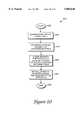
- FIG. 8is a flow diagram illustrating a method 400 of operating and playing game apparatus 10. Although particular microprocessors are described as performing certain steps in the described embodiment, other applicable game components can perform the steps in other embodiments.
- the processbegins at 402.
- step 404initialization and calibration for the game apparatus is performed, preferably when game apparatus 10 is first powered up or reset. Calibration for ambient light levels is performed in step 404.
- the ambient lighting conditionsare recorded for calibration purposes.
- An image of target field 128is preferably recorded by sensing apparatus 130 and stored in memories 216 and 218. An example of such an image is described with reference to FIG. 9. Background pixels in the image of target field 128 are examined to determine ambient lighting conditions, where the background pixels are those pixels describing the surface of target field 128, not target holes or playing pieces.
- a ball intensity thresholdis determined in step 404 using image 440.
- Step 404is preferably implemented when game apparatus 10 is first powered up or reset and is also performed periodically to ensure correct calibration. For example, the recalibration of step 404 can be implemented every two or three hours to compensate for changing ambient lighting conditions during the course of a day. In other embodiments, the position of targets can be precisely located in this step if the targets are to be used as reference points in image analysis. Such an embodiment is described in parent patent application Ser. No. 08/408,618.
- step 406the microprocessor 240 checks if a coin (or other monetary input) has been detected in coin slot 118 by checking input signals from coin switch 180. If no coin is detected, step 408 is implemented for a check for stray objects on target field 128.
- the microprocessor 320uses sensing apparatus 130 to determine if an object has been directed onto target field 128 when a game was not in progress. The microprocessor can detect the object when moving, as accomplished in steps 416 and 418 below; or the object can be detected at rest, as accomplished in step 424 below. If an object is detected, the game apparatus might inform the operator to remove the stray objects, and/or a game might not be allowed to start until the stray object is removed.
- step 408can be implemented only periodically, such as every 10 minutes and/or after a coin is inserted and a game begins. After step 408, the process returns to step 406 to again check for a coin.
- the processor 240receives a target selection from the player and dispenses balls to the player in step 410.
- the playermay preferably select a target hole 136 for which to aim by pressing a target button 112.
- a targetis automatically selected by the game apparatus (e.g., randomly or according to a predetermined pattern), or alternatively the player may aim for any of the provided targets.
- the dispensing of ballsincludes removing the balls from the target field 128 so that the player may place the balls at player end 140 of playing field 106.
- a playing piece dispensercan be used to provide the balls to the player at player end 140.
- the variable BALLSis initialized to zero. This variable stores the amount of balls (or other playing pieces) detected by the game apparatus 10 after being directed by the player.
- a playermay begin to direct playing pieces at this point in the game process. For example, the player can hit a ball 122 through opening 134 in cover 132 with a putting golf club. Players can obtain golf clubs (or other needed equipment) from the operator of the game apparatus.
- step 412is implemented, in which an image 440 of the target field is recorded by sensing apparatus 130 and stored in memories 216 and 218.
- This imagemay show any moving playing pieces on target field 128 and any playing pieces at rest on target field 128.
- This imageis analyzed in step 424, below.
- process 400is implemented so that an image 440 is recorded in step 412 about every 15 milliseconds, although this recording rate can vary in other embodiments.
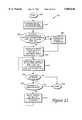
- Steps 414-422may be optionally implemented to validate the directed balls 122 as the balls are moving.
- Validationrefers to the various steps in the current process for determining that a playing piece thrown by the player is a valid playing piece for the game that was provided to the player and not a false or counterfeit playing piece. Validation prevents a player from playing the game with different objects other than the dispensed playing pieces. These validation procedures may not be needed in certain embodiments, such as embodiments having no award dispenser 116 and/or no prizes for players playing the game. In such an embodiment, players may have no real incentive to cheat to gain a high score, and the analysis of the balls at rest in step 424 can be implemented directly after step 412.
- microprocessor 320checks if a moving object has been detected within the range of vision of sensing apparatus 130.
- An "object”, as referred herein,can be a playing piece such as ball 122 or any other object or article which is directed into the field of vision of sensing apparatus 130.
- the image 440 taken in step 412is examined to detect when an object passes into the field of vision by detecting a change of intensity of any pixels in the image.
- Balls 122 pixelshave a different intensity than background target field pixels or pixels of frames 137.
- Microprocessor 320knows an object has been directed by the player when it finds such pixels having a different intensity.
- the microprocessorcan look for pixels that have an intensity value in a predetermined range near the ball intensity value calculated in step 404.
- the ball intensity valueis typically 200 in a range of 0-255
- pixels having an intensity in a range of 190-210can be examined.
- the playing piecescan be detected in image 440 using more elaborate methods, as described below for step 424.
- a different color or other characteristic of the playing piecescan be detected.
- step 424is implemented, detailed below. If a moving object is detected, the microprocessor 320 checks in step 416 if the moving object has a valid identity. This is a validation step to determine if the player is using intended playing pieces, such as standard golf balls or marked golf balls for use with the game apparatus 10. In the preferred embodiment, the identity is determined by examining the size and shape of the playing piece. In alternate embodiments, the identity can also include the color or other characteristics of the playing piece.
- the size of the objectcan be determined by examining the longest portion of the object in image 440 and comparing that portion to a predetermined range of lengths that have been stored in memory. Or, the object can be compared to a spherical shape such as that used for balls 122 (e.g., using a mask as described below for step 424).
- the microprocessorcan compare the size of the object to a range of predetermined sizes to which the size of a valid playing piece should correspond. If the object is determined to be a great degree outside this range of valid sizes (such as by a factor of 2 or more), then the object is assumed to be invalid and the process continues to step 422, described below. If the object is within or marginally outside
- the microprocessor 320can also employ image enhancement techniques (in all the appropriate steps of the current process) to provide a more accurate representation of the object in image 440, if such an enhancement is needed.
- image enhancement techniquesin all the appropriate steps of the current process
- several edge detection methodssuch as Sobel edge detection, are well known to those skilled in the art to provide higher resolution of an edge or other features of an object that have been represented as a collection of pixels.
- the original low resolution imageis processed by these techniques to provide a higher resolution picture.
- microprocessor 320can measure an object more accurately to determine if the object is valid.
- the enhancement techniquescan be used for any step of the process that requires analysis of image 471.
- microprocessor 320can examine all or some of the images recorded during the movement of the object to determine the size and shape of the object, measure different lengths of the object, etc. as it moves or bounces off other playing pieces or targets.
- step 418is implemented, in which microprocessor 320 determines if the moving object has a valid trajectory.
- the microprocessorcan examine a number of successive images 440 to determine a velocity vector or trajectory for the object. Preferably, a minimum of 5 images are examined to determine a trajectory of the object (if the minimum number of images have not been recorded yet, then step 424 is automatically implemented next). If the object is determined to be moving in a direction that is included in predetermined spatial constraints, then the object's trajectory is validated. For example, an object's trajectory can be validated if the object enters image 440 from the front edge at the bottom of the image 440 of FIG. 9 and moves toward a different side of image 440.
- An invalid trajectorymight occur, for example, if a player breaks into housing 103 to throw an object from that position and get easy access to target holes 136, or if a player is able to place a playing piece on a target in target field 128 with his or her hand.
- trajectoriescan be considered valid or invalid in other embodiments.
- additional trajectory validationcan be implemented if desired. For example, the speed of the object as well as the direction can be checked by examining successive images and determining the distance traveled by the object between images. The speed can be calculated since the distance traveled by the object and the time between recorded images is known. Such speed validation might be useful, for example, to invalidate playing pieces that are directed too fast by a player to encourage a safer environment to players.
- step 422is implemented, described below. If the object was found to have a valid trajectory (or if there are not enough images yet recorded to make the validity determination), then step 420 is implemented, in which the variable BALLS is incremented. The process then continues to step 424. If the validation steps 414-322 are not being used in an embodiment, the incrementing of BALLS can be performed in the analysis step 424.
- step 422the detected object is considered invalid from step 416 or step 418 and either the game is ended or the invalidated object is ignored in any further analysis.
- the gamecan be ended when any invalid object is detected during a game, or only for specific types of objects, such as very large objects or very fast-moving objects which could damage the game apparatus 10.
- the invalidated objectcan be ignored in any further analysis, as described above.
- microprocessor 320analyzes image 440 of target field 128 to determine the locations of playing pieces for the purpose of modifying the game score.
- this stepcomprises scanning pixels of the target field image 440 to determine the locations of balls 122 on the playing field. Step 424 is described in greater detail with reference to FIG. 11.
- microprocessor 240calculates a game score based on the information sent by microprocessor 320.
- One or more game score displays 114are also preferably updated accordingly in this step.
- the scoreis determined by the distance of each ball 122 to a designated target hole 136 as indicated in the last-recorded image 440.
- earlier-recorded and/or multiple imagescan be used to determine game score.
- a "designated" holeis intended to refer to the particular hole that the player is aiming for with a particular ball, e.g., a hole that the player selected using controls 112, or a hole that was automatically selected by the game apparatus. In other embodiments, no particular target is selected, and the "designated" hole can be any or all of the target holes provided on target field 128.
- the distance from ball to hole 136can be designated in pixels, inches, or other unit of measure. In the described embodiment, the closer the ball is to the designated hole, the greater the score. A predetermined relationship can be used to determine score based on distance. For example, the inverse of the distance can be provided as the score, and/or a constant can be multiplied by the inverted number. In the described embodiment, if a ball is outside a particular distance from the designated target hole (such as 15 inches), then no points are scored by that ball. Alternatively, the distance itself can be displayed as the score. For example, the distance of each ball to a designated hole is added together, and the player desires to achieve the lowest total score possible. In other embodiments, after each ball is directed by the player, the score display 114 shows the distance of the last directed ball to a designated hole, and also shows the accumulated distance of all balls to designated holes directed during the game.
- the game scorecan be increased by a predetermined number of points for each playing piece in a predetermined scoring position, such as when a ball stops in aperture 139 of a frame 137.
- microprocessor 320can also inform microprocessor 240 about any special scoring conditions. For example, if a ball stops in a special target hole that yields a higher game score (or a special ball lands in a target hole, etc.), processor 320 can inform processor 240 that this condition has occurred. Microprocessor 240 could then increase the game score by a greater amount to reflect the special condition.
- step 428the microprocessor 240 checks if all balls (or other playing pieces) have been directed by the player or if a time limit for the game has expired. Microprocessor 240 checks if BALLS is currently equal to the number of playing pieces that is used with the game apparatus. If so, then the player has hit all of the balls for one game and the game is over. Or, if a predetermined time limit since the last ball was detected has expired, the game is over. Alternatively, a player can be provided with a predetermined time amount to play an entire game; this time limit can be started when the first object is detected by sensing apparatus 130 or when a coin is detected in step 406. An end-game button can also be selected by a player to end the game in some embodiments, as described above. If any of the checks indicate the game is not over, the process returns to step 412.
- the processoptionally can perform after step 428 a final image analysis and game score calculation, similar to steps 424 and 426.
- a final image analysis and game score calculationcan be used in embodiments where only the final positions of the directed balls (at the end of the game) determine the game score. For example, if a player directs a first ball onto target field 128, and then directs a second ball that collides with and moves the first ball to a new position, then the game score based on the first ball's original position should be updated based on the new, final position of the first ball.
- game score for each ballcan be based only on the original rest position of the ball, so that later changes in position of the ball can be ignored.
- different ballscan have different characteristics (markings, color, etc.) to uniquely identify each ball so that the microprocessor can determine which balls have previously been scored after a collision.
- the processthen continues to step 430.
- the balls 122are left resting on target field 128 until a player inserts a coin to start a new game, at which time the balls are removed from the target field and provided to the player.
- microprocessor 240can activate a ball removal mechanism after step 428 to remove all playing pieces from target field 128 and route the balls to the storage area. If an award dispenser is being provided, microprocessor 240 dispenses an award in step 432 to the player from award dispenser 116 based on the final game score. The process then returns to step 406 to check for another coin to be inserted into coin slot 118 by a player.
- a two or more player gamecan also be implemented on game apparatus 10.
- one playercan direct all of his or her golf balls onto target field 128 and receive a score; the other player would then do the same in a different "round” and receive a score, with the higher score winning the game after a predetermined number of rounds.
- playerscan alternate directing balls onto target field 128.
- sensing apparatus 130preferably distinguishes between the two players' balls in order to modify the proper player's score.
- Each player's ballscan be a different color, have different markings, or be provided with other different characteristics to allow the sensing apparatus to distinguish the balls.
- method steps of the current methodcan be performed by microprocessor 240 or 320, microprocessors 240 and 320 can be combined into a single microprocessor, or the microprocessors can be implemented as other types of components.
- FIG. 9illustrates an example of image 440 of target field 128 recorded by sensing apparatus 130 in step 412 of FIG. 8, after three balls have been directed by a player onto the target field.
- This imageis formed and recorded by sensing apparatus 130.
- Image 440preferably is a raster image including rows and columns of pixels, where each pixel has an intensity in a gray scale.
- the field of vision of sensing apparatus 130may be greater than the area of the target field; however, areas of the image 440 that are outside target field 128 are masked out and ignored.
- each pixelhas an intensity value ranging from 0-255 indicating the pixel's shade of gray.
- the pixelsare stored as digital data in data video memories 216 and 218 derived from video data of the CCD, as described above with reference to FIG. 7.
- Each pixelhas characteristic values indicating how bright the pixel is, what gray shade the pixel is, etc.
- a sensing apparatus 130that is operative to record color images can be used, such that the pixels each have a color value rather than (or in addition to) an intensity value.
- Image 440portrays the target field 128 having a background area, which is the "carpet” or simulated putting green in a golf embodiment.
- the pixels of this backgroundpreferably have a low intensity so that they appear dark in image 440.
- These background pixelsare used in the calibration step 404.
- Target holes 136appear in image 440 on the background of target field 128 spaced apart in the particular layout used on target field 128.
- a "fish-eye" or other type of lenscan be used by sensing apparatus 130 to record image 440, as explained in parent application Ser. No. 08/408,618.
- Sensing apparatus 130can be positioned above the center of target field 128.
- Target frames 137can also be distinguished in image 440, although, in the described embodiment, they are not analyzed.
- image 440can be analyzed for pixels having a different intensity (or color) from the target field 128 background to precisely locate each target frame 137 of each hole 136, similarly to the process for locating bottlecaps as described in parent patent application Ser. No. 08/408,618. Or, particular reference areas on the target frames or on the background can be examined.
- the material and surface of frames 137can be provided such that they will appear distinctly from the background of target field 128 and from balls 122.
- Images of balls 122are shown in FIG. 9 in their rest positions after a player has directed them onto the target field.
- Sensing apparatus 130can detect the presence of a ball 122 on target field 128 by detecting a different intensity of pixels in image 440. Pixels describing balls 122 have a much brighter intensity than background pixels in the described embodiment, since the balls are typically white or other bright color.
- a ballcan be detected and validated during image analysis using mask 442, as explained below with reference to FIG. 11.
- control system 144determines a game score based on the distance of balls 122 from designated target holes 136.
- the distancescan be accurately determined from image 440. For example, ball 122a has been hit by a player and comes to rest at the shown position. Previously, by use of front panel 16, the player designated target hole 136a as the desired target for which the player is shooting. Target hole 136a is thus the target referenced when calculating the score.
- the control systemdetermines the distance d1 from the middle of ball 122a to the center 446 of designated target hole 136a. This can be accomplished using a variety of methods.
- the number of pixels between these points in the x- and y-directionscan be counted, and the distance calculated by well-known formulae for calculating a hypotenuse of a triangle.
- the distance in pixelscan be converted to actual measurements in inches or centimeters; or, the distance in pixels need not be converted.
- target hole 136ais again designated as the intended target, and the player directs ball 122b onto target field 128, where it stops in the position shown.
- Microprocessor 320similarly calculates the distance d2 between ball 122b and the center of target hole 136a.
- target hole 136bdesignates target hole 136b as the desired target, and directs ball 122c into the center aperture 139 of frame 137 of target hole 136b.
- the control systempreferably does not need to calculate the distance from the ball to the center of the hole; by directing the ball into the aperture 139, the player has achieved the maximum score. In other embodiments, other factors can be used to determine score, such as the distance of ball 122c from a designated point inside aperture 139 when the ball comes to rest within the aperture 139.
- the scoremight be influenced not by the final rest position of a ball 122, but by the closest distance between the ball and the target at any point along the ball's path (or both the final position and the closest position).
- Data from moving object analysis steps 416 and 418 of FIG. 8can be used for this determination.
- the multiple images recorded during the ball's movement on target field 128can be recorded at a high enough rate so that the closest position of the ball to a designated target can be accurately determined, and a game score is based on the distance from this closest approach to the target.
- Other feedback from game apparatus 10can also be provided based on how close the ball got to a designated target along the path (trajectory) of the ball. For example, audio feedback from speaker 24 in the form of a voice can state that a player "almost made it", was "close”, etc.
- This method of examining the entire trajectory of the ballis preferred in embodiments such as a croquet game.
- a playerdesires to direct ball 122 through one or more upright hoops provided on target field 128.
- Game scoreis based on whether the ball passes through one or more hoops at any point along the ball's trajectory.
- scorecan be further based on the size of a hoop (e.g., smaller hoop yield a greater score than a larger hoop), placement of a hoop on the target field (e.g., front hoops are easier to direct a ball through and thus provide a smaller score than back hoops), and the number of hoops passed through by one ball (e.g., if a ball passes through two hoops, a bonus score can be added).
- size of a hoope.g., smaller hoop yield a greater score than a larger hoop
- placement of a hoop on the target fielde.g., front hoops are easier to direct a ball through and thus provide a smaller score than back hoops
- the number of hoops passed through by one balle.g., if a ball passes through two hoops, a bonus score can be added.
- FIG. 10is a flow diagram illustrating step 404 of FIG. 8, in which initialization and calibration of the game apparatus 10 is performed while a game is not in progress.
- the processbegins at 450, and in step 452, the background of the target field is scanned by sensing apparatus 130 in an image 440 (although no balls 122 are provided on field 128 in this process).
- the average intensity of a number of the recorded background pixelsis determined. For example, background pixels can be sampled from all areas of image 440 to obtain an average value for light reflecting from the entire target field. This average value is later used for the process of FIG. 11.
- an intensity thresholdis lowered until false detections occur at a location on the target field; this step is performed to find the minimum level where detection of pixels occurs in the current ambient lighting conditions.
- a ball maskcan be placed at a background pixel location and using a starting intensity threshold of, for example, 200. The process of detecting a ball using a ball mask and intensity threshold is described below in greater detail with respect to FIG. 11. However, since no ball exists in image 440 at this step, no ball can be found.
- the intensity thresholdis lowered in step 456 until a detection is made; this detection is a false detection.
- the intensity thresholdis raised to a new number in step 458.
- the intensity thresholdis raised by a predetermined amount above the false detection threshold. For example, if white or other bright colors are used on balls 122, then the pixels recorded for balls 122 may be 100 counts brighter than the background pixels in a scale of 0-255. The ball intensity threshold could thus be set 100 counts above the false detection threshold.
- Alternative methods of setting a thresholdcan also be used, such as the method described in parent patent application Ser. No. 08/408,618.
- the processis then complete as indicated at 460.
- the calibration processcan also be performed to recalibrate the intensities after a period of time, the game apparatus is 10 moved, etc.
- FIG. 11is a flow diagram illustrating step 424 of FIG. 8, where the image 440 of the target field is analyzed for balls during a game.
- the processbegins at 462.
- step 464the current intensity of background pixels in image 440 is examined. These pixels can be the same pixels examined in the calibration step 404 as described in step 454 of FIG. 10, or a different sampling of background pixels can be examined. The sampled background pixel intensities can also be averaged, if desired.
- the microprocessor 320checks if the current intensity of the background pixels is different from the average intensity of the background pixels found in the calibration step 404.
- step 468is performed, where the ball intensity threshold is temporarily changed to reflect the changed lighting conditions.
- the ball intensity thresholdcan be modified by the same amount as the difference between the calibrated and current background intensities.
- ⁇ 50% change in light level, etc.other procedures can be implemented. For example, one or more pixels describing the background of the target field 128 can be compared in intensity between the original and current images. If the intensity difference is greater than a predetermined large threshold, then ambient light levels have changed greatly during the course of the game and could cause inaccurate results. Such large light changes can be due to turning on lights, shadows, blocking sunlight through windows, shining a light directly onto sensing apparatus 130, etc. If such a large light change is detected, then several actions can be taken. One action would be to simply invalidate the current game and change the player's score to zero; an error message can also be displayed for the operator of game apparatus 10 to indicate the significant light level changes. Also, the shutter speed of the camera sensor 130 can be adjusted to compensate for the change in light intensity level.
- step 468the process continues to step 470, where a pointer is positioned at a designated first pixel of the recorded image 440.
- the pointerpoints to the pixel that is currently being examined by microprocessor 320.
- the first pixelis preferably a corner pixel, such as the upper left pixel of image 440.
- the microprocessor 320determines if a ball is located at the current location of the pointer, and, if so, the distance between the detected ball and the designated target for that ball. This step is described in greater detail with respect to FIG. 12.
- step 474the microprocessor 320 can check if all the balls intended to be used for one game have been detected in image 440. If all the balls have been detected, the image analysis does not need to continue. For example, if three balls are used in a game, and three balls have already been detected in the current process, there is no need to examine any further pixels in the image. Accordingly, step 475 would be implemented to complete the process. If all balls have not yet been detected, the process continues to step 476. Alternatively, the microprocessor can wait until the entire image has been examined in the current process. If more than the number of balls in the game has been detected in the image, then other false or stray objects have been detected. The objects that are closest in intensity and shape to the valid playing pieces can then be analyzed, while the other objects can be ignored.
- FIG. 12is a flow diagram illustrating step 472 of FIG. 1, in which a ball is checked at the current location of the pointer and, if a ball is found, the distance between the ball and target hole is determined.
- the processbegins at 480, and, in step 481, the microprocessor 320 checks whether the intensity of the pixel at the pointer location (the "current pixel") is greater than the ball intensity threshold determined previously. If not, the process is complete at 485, and the pointer is moved to the next pixel as described in FIG. 11.
- the processfirst checks whether the detected object is at a rest position, i.e., whether the object has stopped moving. This can be accomplished in a variety of ways. In the described embodiment, a predetermined number of the previous, most recently recorded images are examined and compared to the current image to determine if the detected object has moved. For example, the process can examine the current object pixel in a predetermined number of previous images and check if that pixel has a different intensity in one or more of the previous images, which would indicate the detected object is still moving. If the detected object is determined to be still moving, then the process is complete at 485.
- step 482can be omitted, e.g., in embodiments where only the closest approach of the ball to the target on the path of the ball determines game score.
- step 483the microprocessor checks if the object at the current pointer location has been previously examined in the earlier analysis of the current image and in earlier images recorded previously in the game process of FIG. 8. This previous examination would have occurred in the current image when, for example, a high-intensity pixel was found on the horizontal row of pixels just above the current row.
- the microprocessorpreferably stores the locations of balls detected previously in the current image and previous images. Thus, pixels above the intensity threshold are ignored if those pixels are included in a ball that has already been detected and analyzed, and only newly appearing balls are analyzed. Thus, if this ball was previously detected, the process is complete at 485.
- a ball maskis placed at or "over" the image 440 at the estimated center location of the ball image in image 440.
- An example of a ball mask 442is shown in FIG. 9.
- a "mask”, as referred to herein,is a number of pixels, such as a bit map or pixel map, that is stored in memory (preferably program memory 222) and define a shape or image in a predefined area.
- the ball mask 442is a predefined rectangular (or other shaped) map of pixels stored in memory that describe a ball playing piece 122 (the mask can describe other shapes of playing pieces in other embodiments).
- the dark pixels 443, for example,are "0" or off and describe areas outside the dimensions of a ball, and the light pixels 445 are "1" or on and describe the area of pixels covered by a valid ball 122 image as recorded in image 440.
- the ball maskis placed in an estimated center location of a ball on image 440, since the precise location of the ball is not known. Because this is the first pixel of the ball that has been detected (later pixels of this ball are ignored by the check in step 483 above), the center of the ball can be estimated using the scanning direction and the known dimensions of a ball. For example, if the pointer is being scanned in a left-right, top-bottom direction, and a ball pixel is found in step 481, then it is known that the center of the ball will be positioned down and to the right of the first found pixel. If a ball is, for example, generally 12 pixels across, the center of the ball should be about 6 pixels in the down-right direction. Also in step 484, the variable PIXEL -- HITS is initialized to zero. PIXEL -- HITS stores a count of how many image pixels in the mask area have a high enough intensity to be playing piece pixels, as described below.
- Steps 486 to 494are steps for detecting whether a ball is present and for validating that the object is a ball used with the game.
- the microprocessor 320checks if all pixels in the ball mask have been examined (i.e., compared with the corresponding image pixels). If so, then step 496 is implemented as described below. If there are unexamined mask pixels, then the microprocessor examines the next mask pixel in step 488. The "next" mask pixel is the next pixel in a specified order of mask pixels, such as in a left to right, top to bottom order.
- step 490the microprocessor 320 checks if the examined mask pixel is equal to 0, i.e., if the pixel is a dark pixel 443 of mask 442 as shown in FIG. 9. If so, then the process returns to step 486. If not, then step 492 is implemented, where the image pixel of image 440 that corresponds to the examined mask pixel is checked if it is greater than or equal to the ball intensity threshold. In alternate embodiments, a check can be made in this step for color intensity brightness or other characteristic of the image pixels, etc. If the corresponding image pixel intensity is less than the ball intensity threshold, then the process returns to step 486. If the image pixel intensity is greater than the ball intensity threshold, then PIXEL -- HITS is incremented in step 494. The process then returns to step 486 to check for the next pixel of the ball mask.
- microprocessor 320determines in step 486 that all mask pixels have been examined, then in step 496, the microprocessor divides PIXEL -- HITS by the number of pixels in the ball mask. This result is the "mask percentage", the percentage of image pixels in the mask area that have a pixel intensity of a ball. The mask percentage is compared to the mask threshold.
- the mask thresholddefines the minimum percentage of pixels of image 440 that must match pixels of the ball mask for a valid ball to be considered detected.
- the mask thresholdis a number that has been found to work well in tests detecting balls; for example, 70% is a reasonable mask threshold.
- step 498a valid ball is determined to have been located. If desired, an additional check of whether the detected ball is still moving may be performed here--i.e., the ball may still be slightly moving just before it has come to rest, and thus may have passed the check in step 483. The check for movement can be made similarly to that described for step 482.
- step 500the process determines the distance between the located ball and the designated target hole, as described above with respect to FIG. 9.
- a ballis known to be associated with a particular target by its order of detection.
- the first directed ballcan be associated with target hole #1
- the second directed ballcan be associated with target hole #2, etc.
- the microprocessor 240 and/or 320can check which target hole is currently selected and can determine the distance between the detected ball and the currently-selected target (since only a new ball is analyzed in this step). The process is then complete at 485.
- the processcan measure the distances between the balls and the targets at the end of the game, after all balls have been directed onto the target field 128 by the player.
- the target that is closest to each ballis associated with that ball, so that a distance is measured between each ball and the closest target hole.
- the microprocessor 240 or 320can keep track of particular balls and particular targets that were designated to be associated with the balls at the time they were directed onto the target field, and can measure distances at the end of the game between the balls and designated targets.
- Additional testscan also be performed after step 496 to validate that the ball is a valid playing piece.
- the processcan check for surface curvature of a ball by analyzing bright and dark pixels within the ball image caused by shadows. This check prevents flat objects, such as discs, from being detected as a ball. Additional tests can be implemented if further validation of the ball is needed, such as those steps described in parent patent application Ser. No. 08/408,618. When validating different types of playing pieces, surface curvatures, markings, or other characteristics can be detected.
- Step 502is then implemented, in which the microprocessor checks if the mask has been moved to all designated positions. Ball mask is preferably moved to a predetermined number of positions if a failure results from step 496. Microprocessor 320 keeps track of the positions to which the mask has been moved. If the mask has not yet been moved to all of them, then the mask is moved to the next position in step 504. In step 506, the examined mask pixels are reset, and the process returns to step 486. For example, in the described embodiment, ball mask 442 has nine positions. The ball mask can be moved to the right in image 440 (x-coordinate incremented) by one pixel in step 504.
- step 496If failure result again occurs in step 496, then the mask can again be moved one pixel to the right. If, after 3 movements failure still results in step 496, then the mask is reset to its original x position but has a y coordinate incremented (a movement down in image 440). Thus, a 3 ⁇ 3 pixel grid centered around the original mask center point is eventually checked. In alternate embodiments, the mask can be moved greater distances and/or in more positions.
- step 502If the mask has been moved to all predetermined positions in step 502, then no ball has been found at the current image pointer position, and the process is complete at 485.
- the microprocessorcan look at four pixels spaced 90 degrees apart and located a certain distance from the estimated center of the ball. If these four pixels have the desired ball intensity, then further analysis can be performed according to the process 472 described above. If the four pixels are not playing piece pixels, it can be assumed that no ball has been detected.
- balls 122different types or appearances of balls 122 (or other playing pieces) can be used.
- Balls having different attributes or characteristics (identities)can be worth different amounts of points.
- a specially-colored ballmight increase the score by a greater amount than other balls if it stops in a target hole 136.
- a differently-sized or shaped ball or a ball with different markings/indiciamight be worth different amounts of points.
- a different mask similar to those described abovecan be used for each type of ball.
- a color sensing apparatus 130would be more suitable if differently-colored balls are provided, as in the two-player embodiment described above.
Landscapes
- Physics & Mathematics (AREA)
- General Physics & Mathematics (AREA)
- Health & Medical Sciences (AREA)
- General Health & Medical Sciences (AREA)
- Physical Education & Sports Medicine (AREA)
- Engineering & Computer Science (AREA)
- Multimedia (AREA)
- Length Measuring Devices By Optical Means (AREA)
- Image Analysis (AREA)
- Coin-Freed Apparatuses For Hiring Articles (AREA)
Abstract
Description
Claims (51)
Priority Applications (1)
| Application Number | Priority Date | Filing Date | Title |
|---|---|---|---|
| US08/697,961US5860648A (en) | 1995-03-22 | 1996-09-05 | Golfing game including object sensing and validation |
Applications Claiming Priority (2)
| Application Number | Priority Date | Filing Date | Title |
|---|---|---|---|
| US08/408,618US5553859A (en) | 1995-03-22 | 1995-03-22 | Arcade game for sensing and validating objects |
| US08/697,961US5860648A (en) | 1995-03-22 | 1996-09-05 | Golfing game including object sensing and validation |
Related Parent Applications (1)
| Application Number | Title | Priority Date | Filing Date |
|---|---|---|---|
| US08/408,618Continuation-In-PartUS5553859A (en) | 1995-03-22 | 1995-03-22 | Arcade game for sensing and validating objects |
Publications (1)
| Publication Number | Publication Date |
|---|---|
| US5860648Atrue US5860648A (en) | 1999-01-19 |
Family
ID=23617021
Family Applications (2)
| Application Number | Title | Priority Date | Filing Date |
|---|---|---|---|
| US08/408,618Expired - LifetimeUS5553859A (en) | 1995-03-22 | 1995-03-22 | Arcade game for sensing and validating objects |
| US08/697,961Expired - LifetimeUS5860648A (en) | 1995-03-22 | 1996-09-05 | Golfing game including object sensing and validation |
Family Applications Before (1)
| Application Number | Title | Priority Date | Filing Date |
|---|---|---|---|
| US08/408,618Expired - LifetimeUS5553859A (en) | 1995-03-22 | 1995-03-22 | Arcade game for sensing and validating objects |
Country Status (3)
| Country | Link |
|---|---|
| US (2) | US5553859A (en) |
| AU (1) | AU5426796A (en) |
| WO (1) | WO1996029125A1 (en) |
Cited By (87)
| Publication number | Priority date | Publication date | Assignee | Title |
|---|---|---|---|---|
| KR20000006863A (en)* | 1999-11-09 | 2000-02-07 | 홍의식 | Control signal processing system for coin inserting type of golf putting game |
| WO2000041776A1 (en)* | 1999-01-15 | 2000-07-20 | Jonathan Brust | System and method for recording and analyzing a golf swing |
| WO2001007122A1 (en)* | 1999-07-26 | 2001-02-01 | Pierre Conradie | Entertainment equipment |
| US20010038178A1 (en)* | 1998-09-11 | 2001-11-08 | Olaf Vancura | Knowledge-based casino game and method therefor |
| US20030004005A1 (en)* | 2001-06-29 | 2003-01-02 | Ainsworth Clifford L. | Method and apparatus for uniquely identifying a golf ball at a target |
| GB2379614A (en)* | 2001-09-07 | 2003-03-19 | Bell Fruit Games Ltd | An entertainment machine having a means of detecting different playing pieces |
| KR20030026192A (en)* | 2001-09-25 | 2003-03-31 | 넥스콘 월드 주식회사 | A puttingame machine and a method of sensing ball |
| US20030073479A1 (en)* | 2001-09-07 | 2003-04-17 | Richard Wilson | Entertainment machine |
| GB2381757A (en)* | 2001-11-09 | 2003-05-14 | Bell Fruit Games Ltd | A prize giving entertainment machine |
| USD474813S1 (en) | 2001-08-22 | 2003-05-20 | Stephen Brian Wilson | Game |
| US20030125122A1 (en)* | 2000-01-05 | 2003-07-03 | Jolliffe Steven P. | Golf game |
| US6595863B2 (en) | 2000-10-03 | 2003-07-22 | Par Action Golf, Inc. | Golf simulator |
| US6602146B1 (en) | 2000-06-12 | 2003-08-05 | John Pirre | Putting skill game |
| US20030166420A1 (en)* | 2002-03-04 | 2003-09-04 | Jason Chou | Golf practising device having displaying device |
| US20030190962A1 (en)* | 2002-04-05 | 2003-10-09 | Canterbury Stephen A. | System and method for combining low-power signals and high-power signals on a single circuit board in a gaming machine |
| USD483414S1 (en) | 2002-10-29 | 2003-12-09 | Howard Wilson, Sr. | Board game |
| US20040047514A1 (en)* | 2002-09-05 | 2004-03-11 | Eastman Kodak Company | Method for sharpening a digital image |
| US20040053661A1 (en)* | 2002-09-13 | 2004-03-18 | Jones Aaron T. | Wagering gaming device having simulated control of movement of game functional elements |
| US20040072625A1 (en)* | 2002-10-15 | 2004-04-15 | Fertig John K. | Golf game and method of game play using same |
| US6767284B1 (en) | 2000-03-14 | 2004-07-27 | John R. Koza | Skill games |
| US20040235548A1 (en)* | 2002-03-28 | 2004-11-25 | Jamal Benbrahim | Casino gaming apparatus with a bonus |
| US20040267386A1 (en)* | 1999-07-15 | 2004-12-30 | Aaron Hightower | System and method of vehicle competition with enhanced ghosting features |
| US20050059446A1 (en)* | 2003-09-15 | 2005-03-17 | Kaminkow Joseph E. | Gaming device having a segment elimination game |
| US20050192124A1 (en)* | 2004-03-01 | 2005-09-01 | Ultimate Golf Challenge, Inc. | Method and system for implementing a closest to the pin challenge |
| US6964608B1 (en) | 2000-03-14 | 2005-11-15 | John R. Koza | Skill games |
| US20060040735A1 (en)* | 2004-08-20 | 2006-02-23 | Baerlocher Anthony J | Gaming device and method having a first interactive game which determines a function of a second wagering game |
| US20060074921A1 (en)* | 2002-07-24 | 2006-04-06 | Total Immersion | Method and system enabling real time mixing of synthetic images and video images by a user |
| GB2381211B (en)* | 2001-10-23 | 2006-05-03 | Bell Fruit Games Ltd | An entertainment machine |
| US20060116189A1 (en)* | 2001-12-31 | 2006-06-01 | Igt | Method and apparatus for providing an advantage to a player in a bonus game |
| WO2006080622A1 (en)* | 2004-09-21 | 2006-08-03 | Field Club Co., Ltd. | Digital golf putting system |
| US20060189399A1 (en)* | 2005-02-18 | 2006-08-24 | Blue Marlin Llc | Method and imager for determining the point of impact on a putter face |
| US7137900B1 (en) | 2005-06-03 | 2006-11-21 | Van Dyke Peter F | Apparatus and method for practicing golf ball putting |
| US20070054723A1 (en)* | 2005-09-02 | 2007-03-08 | Igt | Video and mechanical spinning bonus wheel |
| US7214138B1 (en)* | 1999-01-29 | 2007-05-08 | Bgi Acquisition, Llc | Golf ball flight monitoring system |
| US20070167205A1 (en)* | 2006-01-10 | 2007-07-19 | Whitfield Richard A | Game apparatus and method |
| US20070197306A1 (en)* | 2006-02-21 | 2007-08-23 | James Ting | Indoor putting game device |
| US20070205553A1 (en)* | 2004-05-26 | 2007-09-06 | Turley Jeffrey D | Apparatus for table golf game |
| GB2436966A (en)* | 2006-04-05 | 2007-10-10 | Tomy Co Ltd | Colour detection game apparatus |
| WO2007087385A3 (en)* | 2006-01-23 | 2007-12-06 | Accu Sport Int Inc | Imaging system and method including multiple, sequentially exposed image sensors |
| WO2007140860A1 (en)* | 2006-06-07 | 2007-12-13 | Friend For Golfers Gmbh | An autarkic golf diagnosis apparatus and a method of manufacturing the same |
| US20080009359A1 (en)* | 2006-06-19 | 2008-01-10 | Tae-Hyok Yun | Putting training apparatus |
| US20080012824A1 (en)* | 2006-07-17 | 2008-01-17 | Anders Grunnet-Jepsen | Free-Space Multi-Dimensional Absolute Pointer Using a Projection Marker System |
| US20080108425A1 (en)* | 2006-11-08 | 2008-05-08 | Igt | Gaming system and method providing an interactive game with automatic wagers |
| WO2008056005A1 (en)* | 2006-11-06 | 2008-05-15 | Delgado Menchaca Jose Pablo | Automatic ball collection installation for golf practice ranges |
| US20080278445A1 (en)* | 2007-05-08 | 2008-11-13 | Thinkoptics, Inc. | Free-space multi-dimensional absolute pointer with improved performance |
| US20090062002A1 (en)* | 2007-08-30 | 2009-03-05 | Bay Tek Games, Inc. | Apparatus And Method of Detecting And Tracking Objects In Amusement Games |
| US20090093324A1 (en)* | 2007-10-03 | 2009-04-09 | Payer Christopher M | Croquet modifying game |
| US20090104964A1 (en)* | 2007-10-17 | 2009-04-23 | Igt | Gaming system, gaming device and gaming method providing player physical activation of the symbol generator |
| EP1547657A4 (en)* | 2002-09-17 | 2010-01-06 | Aruze Corp | GAMING MACHINE AND PROGRAM |
| US20100304825A1 (en)* | 2009-05-29 | 2010-12-02 | Igt | Gaming system, gaming device and method providing competitive wagering games |
| US7950993B2 (en) | 2006-11-08 | 2011-05-31 | Igt | Gaming system and method providing an interactive game with automatic wagers |
| USRE42439E1 (en)* | 1999-05-27 | 2011-06-07 | ArborCom Technologies, Inc. | Canopy modification using computer modelling |
| US20110201437A1 (en)* | 2008-04-25 | 2011-08-18 | Robert Blair Fallow | Golfing Game Apparatus |
| USD648404S1 (en) | 2009-10-02 | 2011-11-08 | Winsor Fun, LLC | Lawn game component |
| US20110294586A1 (en)* | 2009-03-13 | 2011-12-01 | Seong In Cho | Virtual golf simulation device and method for the same |
| US20120183451A1 (en)* | 2009-09-10 | 2012-07-19 | Zheng Shi | Cap sterilizing mechanism for bottle filling device |
| US8231453B2 (en) | 2009-08-25 | 2012-07-31 | Igt | Gaming system, gaming device and method for providing a player an opportunity to win a designated award based on one or more aspects of the player's skill |
| US8366533B1 (en) | 2011-09-21 | 2013-02-05 | Igt | Gaming system, gaming device, and method providing an obstacle board slot game |
| US8366532B1 (en) | 2011-09-21 | 2013-02-05 | Igt | Gaming system, gaming device, and method providing an obstacle board slot game |
| US8398475B2 (en) | 2010-04-27 | 2013-03-19 | Igt | Gaming system, gaming device and method providing a first game and a plurality second wagering games each associated with a separate activatable component of the first game |
| US8409035B1 (en) | 2008-10-03 | 2013-04-02 | Winsor Fun, LLC | Method of playing a field game |
| WO2013156778A1 (en) | 2012-04-18 | 2013-10-24 | David Victor Jolliffe | Ball game apparatus |
| US8696482B1 (en) | 2010-10-05 | 2014-04-15 | Swingbyte, Inc. | Three dimensional golf swing analyzer |
| WO2013141843A3 (en)* | 2012-03-20 | 2014-05-01 | Konami Gaming, Incorporated | Game machine, control method of controlling computer and computer program used therein |
| US20140162798A1 (en)* | 2011-06-02 | 2014-06-12 | Yong Hoon Kim | Housing-type gold-simulation apparatus |
| KR200474335Y1 (en)* | 2013-02-13 | 2014-09-12 | 주)도전하는사람들 | Game Apparatus for Training Golf Putting and Lottering a Free Gift |
| US8907889B2 (en) | 2005-01-12 | 2014-12-09 | Thinkoptics, Inc. | Handheld vision based absolute pointing system |
| US8974316B2 (en) | 2010-04-22 | 2015-03-10 | Joseph Sery | Putting/chipping trainer |
| US20150087432A1 (en)* | 2012-04-18 | 2015-03-26 | Dartslive Co., Ltd. | Golf game device, golf game server, and golf game system |
| GB2526338A (en)* | 2014-05-21 | 2015-11-25 | Automation 4 Ltd | A ball game apparatus |
| WO2016014583A1 (en)* | 2014-07-22 | 2016-01-28 | Bush Shane | System and method for a golf game |
| US9278272B1 (en) | 2015-02-12 | 2016-03-08 | Joseph Sery | Golf training apparatus and method |
| US9416959B2 (en) | 2012-05-17 | 2016-08-16 | Donald Spinner | Illuminated golf |
| US9911286B2 (en) | 2003-10-20 | 2018-03-06 | Igt | Electronic gaming device which determines play information |
| US20180099204A1 (en)* | 2016-10-07 | 2018-04-12 | Remy Couture | Golf putting game and practice tool |
| CN108079551A (en)* | 2017-12-15 | 2018-05-29 | 深圳市梵高夫科技有限公司 | The definite method, apparatus and storage medium of golf reward on total mark |
| JP2018102929A (en)* | 2018-01-05 | 2018-07-05 | コナミゲーミング インコーポレーテッド | Game machine, control method used for the same, and computer program |
| IT201700046516A1 (en)* | 2017-04-28 | 2018-10-28 | Mondo Giochi S R L | ENTERTAINMENT MACHINE |
| US20190105579A1 (en)* | 2017-10-06 | 2019-04-11 | Technologyone, Inc. | Baseplate assembly for use with toy pieces |
| CN111330248A (en)* | 2020-02-19 | 2020-06-26 | 梵高夫科技控股(深圳)有限公司 | Golf entertainment system and golf game method |
| US20220203166A1 (en)* | 2020-12-31 | 2022-06-30 | Vrotein Inc. | Putting guide system |
| US11443596B2 (en) | 2013-07-09 | 2022-09-13 | Igt | Gaming system and method for resuming a skill-based game after an interruption event |
| US11458381B2 (en)* | 2019-07-10 | 2022-10-04 | TP Sports Technologies, LLC | Athletic training device and system |
| US20220355176A1 (en)* | 2021-05-04 | 2022-11-10 | Ron Hollomon | Golf putting training system and method |
| WO2023087047A1 (en)* | 2021-11-19 | 2023-05-25 | Puttchamp Pty Ltd | Ball game apparatus and method therefor |
| USD989878S1 (en)* | 2022-02-01 | 2023-06-20 | Sandstone Media, LLC | Game |
| US11724172B2 (en) | 2015-07-09 | 2023-08-15 | World Golf Systems Limited | Ball game apparatus |
Families Citing this family (30)
| Publication number | Priority date | Publication date | Assignee | Title |
|---|---|---|---|---|
| US5553859A (en)* | 1995-03-22 | 1996-09-10 | Lazer-Tron Corporation | Arcade game for sensing and validating objects |
| US6259827B1 (en) | 1996-03-21 | 2001-07-10 | Cognex Corporation | Machine vision methods for enhancing the contrast between an object and its background using multiple on-axis images |
| US6137893A (en) | 1996-10-07 | 2000-10-24 | Cognex Corporation | Machine vision calibration targets and methods of determining their location and orientation in an image |
| US5678823A (en)* | 1996-10-17 | 1997-10-21 | Bob's Space Racers Inc. | Total solar eclipse game of skill |
| US5960125A (en) | 1996-11-21 | 1999-09-28 | Cognex Corporation | Nonfeedback-based machine vision method for determining a calibration relationship between a camera and a moveable object |
| US6075881A (en) | 1997-03-18 | 2000-06-13 | Cognex Corporation | Machine vision methods for identifying collinear sets of points from an image |
| US6608647B1 (en) | 1997-06-24 | 2003-08-19 | Cognex Corporation | Methods and apparatus for charge coupled device image acquisition with independent integration and readout |
| US5978521A (en)* | 1997-09-25 | 1999-11-02 | Cognex Corporation | Machine vision methods using feedback to determine calibration locations of multiple cameras that image a common object |
| US5978080A (en) | 1997-09-25 | 1999-11-02 | Cognex Corporation | Machine vision methods using feedback to determine an orientation, pixel width and pixel height of a field of view |
| US6381375B1 (en) | 1998-02-20 | 2002-04-30 | Cognex Corporation | Methods and apparatus for generating a projection of an image |
| US6687402B1 (en) | 1998-12-18 | 2004-02-03 | Cognex Corporation | Machine vision methods and systems for boundary feature comparison of patterns and images |
| US6381366B1 (en) | 1998-12-18 | 2002-04-30 | Cognex Corporation | Machine vision methods and system for boundary point-based comparison of patterns and images |
| US6684402B1 (en) | 1999-12-01 | 2004-01-27 | Cognex Technology And Investment Corporation | Control methods and apparatus for coupling multiple image acquisition devices to a digital data processor |
| US6748104B1 (en) | 2000-03-24 | 2004-06-08 | Cognex Corporation | Methods and apparatus for machine vision inspection using single and multiple templates or patterns |
| US7006669B1 (en) | 2000-12-31 | 2006-02-28 | Cognex Corporation | Machine vision method and apparatus for thresholding images of non-uniform materials |
| KR200273826Y1 (en)* | 2002-02-01 | 2002-04-27 | 온스그래픽(주) | Coin-throwing game machine |
| US7757951B2 (en)* | 2005-08-19 | 2010-07-20 | Global Payment Technologies, Inc. | Information readers, apparatuses including information readers, and related methods |
| US7639861B2 (en) | 2005-09-14 | 2009-12-29 | Cognex Technology And Investment Corporation | Method and apparatus for backlighting a wafer during alignment |
| US8111904B2 (en) | 2005-10-07 | 2012-02-07 | Cognex Technology And Investment Corp. | Methods and apparatus for practical 3D vision system |
| US7584890B2 (en)* | 2006-06-23 | 2009-09-08 | Global Payment Technologies, Inc. | Validator linear array |
| US8162584B2 (en) | 2006-08-23 | 2012-04-24 | Cognex Corporation | Method and apparatus for semiconductor wafer alignment |
| US10729973B2 (en)* | 2008-06-30 | 2020-08-04 | Microsoft Technology Licensing, Llc | Dynamic selection of sensor sensitivity in a game input system |
| US8113930B1 (en)* | 2009-02-18 | 2012-02-14 | Coats John O | Dartboard assembly |
| US9189702B2 (en) | 2012-12-31 | 2015-11-17 | Cognex Corporation | Imaging system for determining multi-view alignment |
| RU2561325C1 (en)* | 2014-11-28 | 2015-08-27 | Общество с ограниченной ответственностью "Эксперт-Ч" | Prize attraction |
| US10373343B1 (en)* | 2015-05-28 | 2019-08-06 | Certainteed Corporation | System for visualization of a building material |
| US11195324B1 (en) | 2018-08-14 | 2021-12-07 | Certainteed Llc | Systems and methods for visualization of building structures |
| US10902704B1 (en)* | 2020-08-20 | 2021-01-26 | Stephen P. Shoemaker Trust | Crane game with tubular target holders |
| US20230149800A1 (en)* | 2021-11-16 | 2023-05-18 | Bob's Space Racers, Inc. | Attendant-free game machine |
| US12115425B1 (en) | 2023-09-11 | 2024-10-15 | Puttshack LTD | Standalone and multigame miniature golf structure |
Citations (72)
| Publication number | Priority date | Publication date | Assignee | Title |
|---|---|---|---|---|
| US3268227A (en)* | 1961-05-03 | 1966-08-23 | Jr Samuel A Thatcher | Simulated bowling game with inclined board, cylindrical projectile and indicia target zones |
| US3275325A (en)* | 1964-04-08 | 1966-09-27 | Kenneth W Mackenzie | Golf putting trainer |
| US3584877A (en)* | 1969-01-13 | 1971-06-15 | Raymond J Florian | Golf game |
| US3595581A (en)* | 1966-10-05 | 1971-07-27 | Brunswick Corp | Golf green |
| US3623731A (en)* | 1970-07-23 | 1971-11-30 | Edgar Forcier | Golf putting game |
| US3633911A (en)* | 1968-07-19 | 1972-01-11 | Bertil Ingvar Burstrom | Self-indicating target with slidable target sections |
| US3658343A (en)* | 1968-12-10 | 1972-04-25 | Brunswick Corp | Contourable green with randomly operable contour selection |
| US3854728A (en)* | 1973-08-13 | 1974-12-17 | J Brandell | Golf putting game device |
| US3863922A (en)* | 1970-10-21 | 1975-02-04 | Maurice E Peeples | Golf practice range and method of retrieving balls hit thereon |
| US4023806A (en)* | 1975-10-28 | 1977-05-17 | Wiser John A | Tiltable game surface device |
| US4055349A (en)* | 1976-04-21 | 1977-10-25 | Hunt Archie F | Golf putting practice device having mechanical calculators |
| US4114887A (en)* | 1976-10-01 | 1978-09-19 | Delraso Americo | Golf putting game apparatus |
| US4130280A (en)* | 1977-12-20 | 1978-12-19 | Joseph Lowell | Game apparatus |
| US4130281A (en)* | 1977-07-29 | 1978-12-19 | Leber Ralph E | Horseshoe pitching game apparatus |
| US4150825A (en)* | 1977-07-18 | 1979-04-24 | Wilson Robert F | Golf game simulating apparatus |
| US4171812A (en)* | 1978-06-19 | 1979-10-23 | Marsin Daniel J | Mechanical golf green |
| US4177994A (en)* | 1976-12-20 | 1979-12-11 | University Of Iowa Research Foundation | Golf game and practice apparatus |
| US4195920A (en)* | 1970-09-04 | 1980-04-01 | Brunswick Corporation | Golf game projector |
| US4215865A (en)* | 1978-08-10 | 1980-08-05 | Pilati Oliver H | Golf game |
| US4247112A (en)* | 1978-06-29 | 1981-01-27 | Americo Del Raso | Golfing putting game apparatus |
| US4320902A (en)* | 1981-02-23 | 1982-03-23 | Florkey Arthur G | Pitching track game |
| US4336939A (en)* | 1980-12-05 | 1982-06-29 | Krumlauf Alfred C | Golf chip and putt practice device and game |
| US4343469A (en)* | 1979-05-07 | 1982-08-10 | Nippon Gakki Seizo Kabushiki Kaisha | Golf game practicing apparatus |
| US4461477A (en)* | 1982-06-14 | 1984-07-24 | Stewart Eddie A | Method and apparatus for improving the performance of a batter |
| US4545576A (en)* | 1982-01-15 | 1985-10-08 | Harris Thomas M | Baseball-strike indicator and trajectory analyzer and method of using same |
| US4563005A (en)* | 1984-01-10 | 1986-01-07 | Fortune 100, Inc. | Apparatus for evaluating baseball pitching performance |
| US4572512A (en)* | 1982-09-30 | 1986-02-25 | Tegart Harold G | Golf course |
| US4611809A (en)* | 1985-01-04 | 1986-09-16 | Irvin Gettelfinger | Golf putting practice apparatus |
| US4634130A (en)* | 1985-09-11 | 1987-01-06 | Command Automation, Inc. | Golf practice putting device |
| US4696474A (en)* | 1982-09-30 | 1987-09-29 | Tegart Harold G | Golf course |
| US4763903A (en)* | 1986-01-31 | 1988-08-16 | Max W. Goodwin | Target scoring and display system and method |
| US4767121A (en)* | 1984-12-05 | 1988-08-30 | Joytec Ltd. | Apparatus for simulating play on a golf course or driving range |
| US4789163A (en)* | 1987-06-11 | 1988-12-06 | Warner Larry W | Indoor horseshoe pitching game |
| US4789932A (en)* | 1984-09-21 | 1988-12-06 | Austin T. Musselman | Apparatus and method for automatically scoring a dart game |
| US4798385A (en)* | 1982-09-30 | 1989-01-17 | Tegart Harold G | Double ended golf course |
| US4828267A (en)* | 1988-01-07 | 1989-05-09 | Ray Goodrich | Putting practicing device |
| US4858922A (en)* | 1988-07-12 | 1989-08-22 | Intermark Amusements, Inc. | Method and apparatus for determining the velocity and path of travel of a ball |
| US4915384A (en)* | 1988-07-21 | 1990-04-10 | Bear Robert A | Player adaptive sports training system |
| US4927160A (en)* | 1989-01-23 | 1990-05-22 | Thomas W. Nichol | Electronic bag toss game with light-activated detection |
| US4941662A (en)* | 1988-11-14 | 1990-07-17 | Deperna James | Baseball game |
| US4956775A (en)* | 1985-10-01 | 1990-09-11 | Klamer R B | Object sensor for detecting characteristics such as color for games |
| US4993709A (en)* | 1987-10-05 | 1991-02-19 | Pan Pacific Corporation | Ball game apparatus |
| US4995607A (en)* | 1988-08-31 | 1991-02-26 | Whitfield Terry B | Interactive sports training device |
| US5024441A (en)* | 1988-04-07 | 1991-06-18 | Claude Rousseau | Golfcourse simulator device |
| US5042813A (en)* | 1990-02-15 | 1991-08-27 | Huang Kuo Shyang | Indoor golf training course |
| US5062641A (en)* | 1989-09-28 | 1991-11-05 | Nannette Poillon | Projectile trajectory determination system |
| US5067718A (en)* | 1991-01-02 | 1991-11-26 | Golf Vegas International, Inc. | Rolling ball speed and position indicating device and method |
| US5082262A (en)* | 1991-07-15 | 1992-01-21 | Sanchez Richard D | Training device for baseball batter and method therefor |
| US5087045A (en)* | 1990-02-26 | 1992-02-11 | Samuel Kim | Putting green with adjustable topography and multi-ball return |
| US5092602A (en)* | 1990-11-26 | 1992-03-03 | Witler James L | Golfing apparatus |
| US5100145A (en)* | 1990-02-26 | 1992-03-31 | Samuel Kim | Putting green with adjustable topography and multi-ball return |
| US5102141A (en)* | 1989-07-17 | 1992-04-07 | Mulay Plastics Inc. | Golf putting practice device |
| US5102140A (en)* | 1991-01-24 | 1992-04-07 | Gene Vincent | Automated hole-in-one recording system |
| US5108101A (en)* | 1991-03-04 | 1992-04-28 | Postula Victor A | Method of playing a lag and bump putting game |
| US5112054A (en)* | 1990-03-15 | 1992-05-12 | Gordon Oswald | Golf park |
| US5118105A (en)* | 1988-04-18 | 1992-06-02 | Brunswick Bowling & Billiards Corporation | Bowling statistics display system |
| US5129653A (en)* | 1991-08-01 | 1992-07-14 | Habitat International, Inc. | Golf putting trainer |
| US5150898A (en)* | 1991-02-11 | 1992-09-29 | Rare Coin-It, Inc. | Game apparatus |
| US5163683A (en)* | 1990-03-15 | 1992-11-17 | Gordon Oswald | Golf park |
| US5163677A (en)* | 1990-12-03 | 1992-11-17 | Foley Derek F | Golf driving range |
| US5174574A (en)* | 1991-01-02 | 1992-12-29 | Golf Vegas International, Inc. | Putting target |
| US5184824A (en)* | 1990-07-03 | 1993-02-09 | Riedinger Thomas R | Golf facility and method |
| US5201521A (en)* | 1991-03-22 | 1993-04-13 | Healy Charles W | Putting practice and game apparatus |
| US5225185A (en)* | 1990-04-30 | 1993-07-06 | Revlon Consumer Products Corporation | Nail enamels containing glyceryl, glycol or citrate esters |
| US5242169A (en)* | 1992-06-17 | 1993-09-07 | Douglas & Laabs, Inc. | Golf putting practice device |
| US5375832A (en)* | 1990-11-26 | 1994-12-27 | Witler; James L. | Golfing apparatus |
| US5395115A (en)* | 1991-01-18 | 1995-03-07 | Ferns; Derek | Golfing facility |
| US5398936A (en)* | 1992-04-29 | 1995-03-21 | Accu-Sport International, Inc. | Golfing apparatus and method for golf play simulation |
| US5401018A (en)* | 1992-11-13 | 1995-03-28 | Lazer-Tron Corporation | Baseball simulation game |
| US5439224A (en)* | 1992-06-05 | 1995-08-08 | Bertoncino; James | Driving range with automated scoring system |
| US5478077A (en)* | 1993-03-31 | 1995-12-26 | Elm Inc. | Object collision point detecting apparatus |
| US5553859A (en)* | 1995-03-22 | 1996-09-10 | Lazer-Tron Corporation | Arcade game for sensing and validating objects |
Family Cites Families (2)
| Publication number | Priority date | Publication date | Assignee | Title |
|---|---|---|---|---|
| US2148346A (en)* | 1938-04-26 | 1939-02-21 | Goldman Moses | Amusement device |
| US5292127C1 (en)* | 1992-10-02 | 2001-05-22 | Arcade Planet Inc | Arcade game |
- 1995
- 1995-03-22USUS08/408,618patent/US5553859A/ennot_activeExpired - Lifetime
- 1996
- 1996-03-21AUAU54267/96Apatent/AU5426796A/ennot_activeAbandoned
- 1996-03-21WOPCT/US1996/003871patent/WO1996029125A1/enactiveApplication Filing
- 1996-09-05USUS08/697,961patent/US5860648A/ennot_activeExpired - Lifetime
Patent Citations (76)
| Publication number | Priority date | Publication date | Assignee | Title |
|---|---|---|---|---|
| US3268227A (en)* | 1961-05-03 | 1966-08-23 | Jr Samuel A Thatcher | Simulated bowling game with inclined board, cylindrical projectile and indicia target zones |
| US3275325A (en)* | 1964-04-08 | 1966-09-27 | Kenneth W Mackenzie | Golf putting trainer |
| US3595581A (en)* | 1966-10-05 | 1971-07-27 | Brunswick Corp | Golf green |
| US3633911A (en)* | 1968-07-19 | 1972-01-11 | Bertil Ingvar Burstrom | Self-indicating target with slidable target sections |
| US3658343A (en)* | 1968-12-10 | 1972-04-25 | Brunswick Corp | Contourable green with randomly operable contour selection |
| US3584877A (en)* | 1969-01-13 | 1971-06-15 | Raymond J Florian | Golf game |
| US3623731A (en)* | 1970-07-23 | 1971-11-30 | Edgar Forcier | Golf putting game |
| US4195920A (en)* | 1970-09-04 | 1980-04-01 | Brunswick Corporation | Golf game projector |
| US3863922A (en)* | 1970-10-21 | 1975-02-04 | Maurice E Peeples | Golf practice range and method of retrieving balls hit thereon |
| US3854728A (en)* | 1973-08-13 | 1974-12-17 | J Brandell | Golf putting game device |
| US4023806A (en)* | 1975-10-28 | 1977-05-17 | Wiser John A | Tiltable game surface device |
| US4070025A (en)* | 1975-10-28 | 1978-01-24 | Wiser John A | Tiltable game surface device |
| US4055349A (en)* | 1976-04-21 | 1977-10-25 | Hunt Archie F | Golf putting practice device having mechanical calculators |
| US4114887A (en)* | 1976-10-01 | 1978-09-19 | Delraso Americo | Golf putting game apparatus |
| US4177994A (en)* | 1976-12-20 | 1979-12-11 | University Of Iowa Research Foundation | Golf game and practice apparatus |
| US4150825A (en)* | 1977-07-18 | 1979-04-24 | Wilson Robert F | Golf game simulating apparatus |
| US4130281A (en)* | 1977-07-29 | 1978-12-19 | Leber Ralph E | Horseshoe pitching game apparatus |
| US4130280A (en)* | 1977-12-20 | 1978-12-19 | Joseph Lowell | Game apparatus |
| US4171812A (en)* | 1978-06-19 | 1979-10-23 | Marsin Daniel J | Mechanical golf green |
| US4247112A (en)* | 1978-06-29 | 1981-01-27 | Americo Del Raso | Golfing putting game apparatus |
| US4215865A (en)* | 1978-08-10 | 1980-08-05 | Pilati Oliver H | Golf game |
| US4343469A (en)* | 1979-05-07 | 1982-08-10 | Nippon Gakki Seizo Kabushiki Kaisha | Golf game practicing apparatus |
| US4336939A (en)* | 1980-12-05 | 1982-06-29 | Krumlauf Alfred C | Golf chip and putt practice device and game |
| US4320902A (en)* | 1981-02-23 | 1982-03-23 | Florkey Arthur G | Pitching track game |
| US4545576A (en)* | 1982-01-15 | 1985-10-08 | Harris Thomas M | Baseball-strike indicator and trajectory analyzer and method of using same |
| US4461477A (en)* | 1982-06-14 | 1984-07-24 | Stewart Eddie A | Method and apparatus for improving the performance of a batter |
| US4696474A (en)* | 1982-09-30 | 1987-09-29 | Tegart Harold G | Golf course |
| US4572512A (en)* | 1982-09-30 | 1986-02-25 | Tegart Harold G | Golf course |
| US4798385A (en)* | 1982-09-30 | 1989-01-17 | Tegart Harold G | Double ended golf course |
| US4563005A (en)* | 1984-01-10 | 1986-01-07 | Fortune 100, Inc. | Apparatus for evaluating baseball pitching performance |
| US4789932A (en)* | 1984-09-21 | 1988-12-06 | Austin T. Musselman | Apparatus and method for automatically scoring a dart game |
| US4767121A (en)* | 1984-12-05 | 1988-08-30 | Joytec Ltd. | Apparatus for simulating play on a golf course or driving range |
| US4611809A (en)* | 1985-01-04 | 1986-09-16 | Irvin Gettelfinger | Golf putting practice apparatus |
| US4634130A (en)* | 1985-09-11 | 1987-01-06 | Command Automation, Inc. | Golf practice putting device |
| US4956775A (en)* | 1985-10-01 | 1990-09-11 | Klamer R B | Object sensor for detecting characteristics such as color for games |
| US4763903A (en)* | 1986-01-31 | 1988-08-16 | Max W. Goodwin | Target scoring and display system and method |
| US4789163A (en)* | 1987-06-11 | 1988-12-06 | Warner Larry W | Indoor horseshoe pitching game |
| US4993709A (en)* | 1987-10-05 | 1991-02-19 | Pan Pacific Corporation | Ball game apparatus |
| US4828267A (en)* | 1988-01-07 | 1989-05-09 | Ray Goodrich | Putting practicing device |
| US5024441A (en)* | 1988-04-07 | 1991-06-18 | Claude Rousseau | Golfcourse simulator device |
| US5118105A (en)* | 1988-04-18 | 1992-06-02 | Brunswick Bowling & Billiards Corporation | Bowling statistics display system |
| US4858922A (en)* | 1988-07-12 | 1989-08-22 | Intermark Amusements, Inc. | Method and apparatus for determining the velocity and path of travel of a ball |
| US4915384A (en)* | 1988-07-21 | 1990-04-10 | Bear Robert A | Player adaptive sports training system |
| US4995607A (en)* | 1988-08-31 | 1991-02-26 | Whitfield Terry B | Interactive sports training device |
| US4941662A (en)* | 1988-11-14 | 1990-07-17 | Deperna James | Baseball game |
| US4927160A (en)* | 1989-01-23 | 1990-05-22 | Thomas W. Nichol | Electronic bag toss game with light-activated detection |
| US5102141A (en)* | 1989-07-17 | 1992-04-07 | Mulay Plastics Inc. | Golf putting practice device |
| US5062641A (en)* | 1989-09-28 | 1991-11-05 | Nannette Poillon | Projectile trajectory determination system |
| US5042813A (en)* | 1990-02-15 | 1991-08-27 | Huang Kuo Shyang | Indoor golf training course |
| US5301947A (en)* | 1990-02-26 | 1994-04-12 | Samuel Kim | Putting green with adjustable topography and multi-ball return |
| US5100145A (en)* | 1990-02-26 | 1992-03-31 | Samuel Kim | Putting green with adjustable topography and multi-ball return |
| US5087045A (en)* | 1990-02-26 | 1992-02-11 | Samuel Kim | Putting green with adjustable topography and multi-ball return |
| US5318303A (en)* | 1990-02-26 | 1994-06-07 | Samuel Kim | Putting green with adjustable topography and multi-ball return |
| US5163683A (en)* | 1990-03-15 | 1992-11-17 | Gordon Oswald | Golf park |
| US5112054A (en)* | 1990-03-15 | 1992-05-12 | Gordon Oswald | Golf park |
| US5225185A (en)* | 1990-04-30 | 1993-07-06 | Revlon Consumer Products Corporation | Nail enamels containing glyceryl, glycol or citrate esters |
| US5184824A (en)* | 1990-07-03 | 1993-02-09 | Riedinger Thomas R | Golf facility and method |
| US5092602A (en)* | 1990-11-26 | 1992-03-03 | Witler James L | Golfing apparatus |
| US5375832A (en)* | 1990-11-26 | 1994-12-27 | Witler; James L. | Golfing apparatus |
| US5290037A (en)* | 1990-11-26 | 1994-03-01 | Witler James L | Golfing apparatus |
| US5163677A (en)* | 1990-12-03 | 1992-11-17 | Foley Derek F | Golf driving range |
| US5174574A (en)* | 1991-01-02 | 1992-12-29 | Golf Vegas International, Inc. | Putting target |
| US5067718A (en)* | 1991-01-02 | 1991-11-26 | Golf Vegas International, Inc. | Rolling ball speed and position indicating device and method |
| US5395115A (en)* | 1991-01-18 | 1995-03-07 | Ferns; Derek | Golfing facility |
| US5102140A (en)* | 1991-01-24 | 1992-04-07 | Gene Vincent | Automated hole-in-one recording system |
| US5150898A (en)* | 1991-02-11 | 1992-09-29 | Rare Coin-It, Inc. | Game apparatus |
| US5108101A (en)* | 1991-03-04 | 1992-04-28 | Postula Victor A | Method of playing a lag and bump putting game |
| US5201521A (en)* | 1991-03-22 | 1993-04-13 | Healy Charles W | Putting practice and game apparatus |
| US5082262A (en)* | 1991-07-15 | 1992-01-21 | Sanchez Richard D | Training device for baseball batter and method therefor |
| US5129653A (en)* | 1991-08-01 | 1992-07-14 | Habitat International, Inc. | Golf putting trainer |
| US5398936A (en)* | 1992-04-29 | 1995-03-21 | Accu-Sport International, Inc. | Golfing apparatus and method for golf play simulation |
| US5439224A (en)* | 1992-06-05 | 1995-08-08 | Bertoncino; James | Driving range with automated scoring system |
| US5242169A (en)* | 1992-06-17 | 1993-09-07 | Douglas & Laabs, Inc. | Golf putting practice device |
| US5401018A (en)* | 1992-11-13 | 1995-03-28 | Lazer-Tron Corporation | Baseball simulation game |
| US5478077A (en)* | 1993-03-31 | 1995-12-26 | Elm Inc. | Object collision point detecting apparatus |
| US5553859A (en)* | 1995-03-22 | 1996-09-10 | Lazer-Tron Corporation | Arcade game for sensing and validating objects |
Non-Patent Citations (6)
| Title |
|---|
| "Go for the Green," G.L. Technology, Inc., 1996. |
| "Putting Challenge II," G.L. Technology, Inc., 1996. |
| "Putting Challenge, A Stroke of Genius," Ice, No Date. |
| Go for the Green, G.L. Technology, Inc., 1996.* |
| Putting Challenge II, G.L. Technology, Inc., 1996.* |
| Putting Challenge, A Stroke of Genius, Ice, No Date.* |
Cited By (164)
| Publication number | Priority date | Publication date | Assignee | Title |
|---|---|---|---|---|
| US20010038178A1 (en)* | 1998-09-11 | 2001-11-08 | Olaf Vancura | Knowledge-based casino game and method therefor |
| US7572182B2 (en) | 1998-09-11 | 2009-08-11 | Igt | Knowledge-based casino game and method therefor |
| WO2000041776A1 (en)* | 1999-01-15 | 2000-07-20 | Jonathan Brust | System and method for recording and analyzing a golf swing |
| US20070213139A1 (en)* | 1999-01-29 | 2007-09-13 | Keith Stivers | Golf ball flight monitoring system |
| US7214138B1 (en)* | 1999-01-29 | 2007-05-08 | Bgi Acquisition, Llc | Golf ball flight monitoring system |
| USRE42439E1 (en)* | 1999-05-27 | 2011-06-07 | ArborCom Technologies, Inc. | Canopy modification using computer modelling |
| US20040267386A1 (en)* | 1999-07-15 | 2004-12-30 | Aaron Hightower | System and method of vehicle competition with enhanced ghosting features |
| WO2001007122A1 (en)* | 1999-07-26 | 2001-02-01 | Pierre Conradie | Entertainment equipment |
| KR20000006863A (en)* | 1999-11-09 | 2000-02-07 | 홍의식 | Control signal processing system for coin inserting type of golf putting game |
| US7040998B2 (en)* | 2000-01-05 | 2006-05-09 | World Golf Systems, Ltd. | Golf putting game with means for automatically monitoring the movement of the ball |
| US20030125122A1 (en)* | 2000-01-05 | 2003-07-03 | Jolliffe Steven P. | Golf game |
| US6964608B1 (en) | 2000-03-14 | 2005-11-15 | John R. Koza | Skill games |
| US6767284B1 (en) | 2000-03-14 | 2004-07-27 | John R. Koza | Skill games |
| US6602146B1 (en) | 2000-06-12 | 2003-08-05 | John Pirre | Putting skill game |
| US6595863B2 (en) | 2000-10-03 | 2003-07-22 | Par Action Golf, Inc. | Golf simulator |
| US20030004005A1 (en)* | 2001-06-29 | 2003-01-02 | Ainsworth Clifford L. | Method and apparatus for uniquely identifying a golf ball at a target |
| US6974391B2 (en)* | 2001-06-29 | 2005-12-13 | Ainsworth Clifford L | Method and apparatus for uniquely identifying a golf ball at a target |
| USD474813S1 (en) | 2001-08-22 | 2003-05-20 | Stephen Brian Wilson | Game |
| US20030073479A1 (en)* | 2001-09-07 | 2003-04-17 | Richard Wilson | Entertainment machine |
| US7172197B2 (en) | 2001-09-07 | 2007-02-06 | Bell-Fruit Games Limited | Entertainment machine |
| GB2379614A (en)* | 2001-09-07 | 2003-03-19 | Bell Fruit Games Ltd | An entertainment machine having a means of detecting different playing pieces |
| GB2379614B (en)* | 2001-09-07 | 2005-03-30 | Bell Fruit Games Ltd | Entertainment machine |
| KR20030026192A (en)* | 2001-09-25 | 2003-03-31 | 넥스콘 월드 주식회사 | A puttingame machine and a method of sensing ball |
| GB2381211B (en)* | 2001-10-23 | 2006-05-03 | Bell Fruit Games Ltd | An entertainment machine |
| GB2381757A (en)* | 2001-11-09 | 2003-05-14 | Bell Fruit Games Ltd | A prize giving entertainment machine |
| US8585482B2 (en) | 2001-12-31 | 2013-11-19 | Igt | Method and apparatus for providing an advantage to a player in a bonus game |
| US7914372B2 (en) | 2001-12-31 | 2011-03-29 | Igt | Method and apparatus for providing an advantage to a player in a bonus game |
| US20080234034A1 (en)* | 2001-12-31 | 2008-09-25 | Igt | Method and apparatus for providing an advantage to a player in a bonus game |
| US20080300050A1 (en)* | 2001-12-31 | 2008-12-04 | Igt | Method and apparatus for providing an advantage to a player in a bonus game |
| US7357714B2 (en) | 2001-12-31 | 2008-04-15 | Igt | Method and apparatus for providing an advantage to a player in a bonus game |
| US20060116189A1 (en)* | 2001-12-31 | 2006-06-01 | Igt | Method and apparatus for providing an advantage to a player in a bonus game |
| US20110111841A1 (en)* | 2001-12-31 | 2011-05-12 | Igt | Method and apparatus for providing an advantage to a player in a bonus game |
| US8317589B2 (en) | 2001-12-31 | 2012-11-27 | Igt | Method and apparatus for providing an advantage to a player in a bonus game |
| US7785186B2 (en) | 2001-12-31 | 2010-08-31 | Igt | Method and apparatus for providing an advantage to a player in a bonus game |
| US8777715B2 (en) | 2001-12-31 | 2014-07-15 | Igt | Method and apparatus for providing an advantage to a player in a bonus game |
| US20030166420A1 (en)* | 2002-03-04 | 2003-09-04 | Jason Chou | Golf practising device having displaying device |
| US7976382B2 (en) | 2002-03-28 | 2011-07-12 | Igt | Casino gaming apparatus with a bonus associated with a cash out |
| US20040235548A1 (en)* | 2002-03-28 | 2004-11-25 | Jamal Benbrahim | Casino gaming apparatus with a bonus |
| US20070149269A1 (en)* | 2002-03-28 | 2007-06-28 | Igt | Casino gaming apparatus with a bonus |
| US7169047B2 (en) | 2002-03-28 | 2007-01-30 | Igt | Providing an indication of a hidden bonus on a casino gaming apparatus |
| US20030190962A1 (en)* | 2002-04-05 | 2003-10-09 | Canterbury Stephen A. | System and method for combining low-power signals and high-power signals on a single circuit board in a gaming machine |
| US7637816B2 (en)* | 2002-04-05 | 2009-12-29 | Wms Gaming Inc. | System and method for combining low-power signals and high-power signals on a single circuit board in a gaming machine |
| US7471301B2 (en)* | 2002-07-24 | 2008-12-30 | Total Immersion | Method and system enabling real time mixing of synthetic images and video images by a user |
| US20060074921A1 (en)* | 2002-07-24 | 2006-04-06 | Total Immersion | Method and system enabling real time mixing of synthetic images and video images by a user |
| US20040047514A1 (en)* | 2002-09-05 | 2004-03-11 | Eastman Kodak Company | Method for sharpening a digital image |
| US7228004B2 (en)* | 2002-09-05 | 2007-06-05 | Eastman Kodak Company | Method for sharpening a digital image |
| US7789756B2 (en) | 2002-09-13 | 2010-09-07 | Igt | Wagering gaming device having simulated control of movement of game functional elements |
| US8075384B2 (en) | 2002-09-13 | 2011-12-13 | Igt | Wagering gaming device having simulated control of movement of game functional elements |
| US9005001B2 (en) | 2002-09-13 | 2015-04-14 | Igt | Wagering gaming device having simulated control of movement of game functional elements |
| US9147310B2 (en) | 2002-09-13 | 2015-09-29 | Igt | Wagering gaming device having simulated control of movement of game functional elements |
| US9600956B2 (en) | 2002-09-13 | 2017-03-21 | Igt | Wagering gaming device having simulated control of movement of game functional elements |
| US20040053661A1 (en)* | 2002-09-13 | 2004-03-18 | Jones Aaron T. | Wagering gaming device having simulated control of movement of game functional elements |
| US20110159944A1 (en)* | 2002-09-13 | 2011-06-30 | Igt | Wagering gaming device having simulated control of movement of game functional elements |
| EP1547657A4 (en)* | 2002-09-17 | 2010-01-06 | Aruze Corp | GAMING MACHINE AND PROGRAM |
| US20040072625A1 (en)* | 2002-10-15 | 2004-04-15 | Fertig John K. | Golf game and method of game play using same |
| USD483414S1 (en) | 2002-10-29 | 2003-12-09 | Howard Wilson, Sr. | Board game |
| US20050059446A1 (en)* | 2003-09-15 | 2005-03-17 | Kaminkow Joseph E. | Gaming device having a segment elimination game |
| US9911286B2 (en) | 2003-10-20 | 2018-03-06 | Igt | Electronic gaming device which determines play information |
| US20050192124A1 (en)* | 2004-03-01 | 2005-09-01 | Ultimate Golf Challenge, Inc. | Method and system for implementing a closest to the pin challenge |
| US20070205553A1 (en)* | 2004-05-26 | 2007-09-06 | Turley Jeffrey D | Apparatus for table golf game |
| US7967674B2 (en) | 2004-08-20 | 2011-06-28 | Igt | Gaming device and method having a first interactive game which determines a function of a second wagering game |
| US7326115B2 (en) | 2004-08-20 | 2008-02-05 | Igt | Gaming device and method having a first interactive game which determines a function of a second wagering game |
| US20060040735A1 (en)* | 2004-08-20 | 2006-02-23 | Baerlocher Anthony J | Gaming device and method having a first interactive game which determines a function of a second wagering game |
| US8267765B2 (en) | 2004-08-20 | 2012-09-18 | Igt | Gaming device and method having a first interactive game which determines a function of a second wagering game |
| WO2006080622A1 (en)* | 2004-09-21 | 2006-08-03 | Field Club Co., Ltd. | Digital golf putting system |
| US8907889B2 (en) | 2005-01-12 | 2014-12-09 | Thinkoptics, Inc. | Handheld vision based absolute pointing system |
| US20060189398A1 (en)* | 2005-02-18 | 2006-08-24 | Blue Marlin Llc | Method and system for determining club head speed |
| US20060189399A1 (en)* | 2005-02-18 | 2006-08-24 | Blue Marlin Llc | Method and imager for determining the point of impact on a putter face |
| US7255647B2 (en)* | 2005-02-18 | 2007-08-14 | Blue Marlin | Method and system for determining club head speed |
| US7384343B2 (en)* | 2005-02-18 | 2008-06-10 | Blue Marlin Llc | Method and imager for determining the point of impact on a putter face |
| US7364396B2 (en) | 2005-06-03 | 2008-04-29 | Van Dyke Peter F | Apparatus and method for practicing golf ball putting |
| US7137900B1 (en) | 2005-06-03 | 2006-11-21 | Van Dyke Peter F | Apparatus and method for practicing golf ball putting |
| US20060276254A1 (en)* | 2005-06-03 | 2006-12-07 | Van Dyke Peter F | Apparatus and method for practicing golf ball putting |
| US20070078019A1 (en)* | 2005-06-03 | 2007-04-05 | Van Dyke Peter F | Apparatus and Method for Practicing Golf Ball Putting |
| US20070054723A1 (en)* | 2005-09-02 | 2007-03-08 | Igt | Video and mechanical spinning bonus wheel |
| US9552686B2 (en) | 2005-09-02 | 2017-01-24 | Igt | Video and mechanical spinning bonus wheel |
| US8771051B2 (en) | 2005-09-02 | 2014-07-08 | Igt | Video and mechanical spinning bonus wheel |
| US20070167205A1 (en)* | 2006-01-10 | 2007-07-19 | Whitfield Richard A | Game apparatus and method |
| US7744479B2 (en)* | 2006-01-10 | 2010-06-29 | Whitfield Richard A | Golf practice game apparatus with sensors |
| WO2007087385A3 (en)* | 2006-01-23 | 2007-12-06 | Accu Sport Int Inc | Imaging system and method including multiple, sequentially exposed image sensors |
| US7294062B2 (en)* | 2006-02-21 | 2007-11-13 | James Ting | Indoor putting game device |
| US20070197306A1 (en)* | 2006-02-21 | 2007-08-23 | James Ting | Indoor putting game device |
| GB2436966A (en)* | 2006-04-05 | 2007-10-10 | Tomy Co Ltd | Colour detection game apparatus |
| WO2007140860A1 (en)* | 2006-06-07 | 2007-12-13 | Friend For Golfers Gmbh | An autarkic golf diagnosis apparatus and a method of manufacturing the same |
| US7566275B2 (en)* | 2006-06-19 | 2009-07-28 | Sun Chul Yun | Golf putting training apparatus |
| US20080009359A1 (en)* | 2006-06-19 | 2008-01-10 | Tae-Hyok Yun | Putting training apparatus |
| US8913003B2 (en) | 2006-07-17 | 2014-12-16 | Thinkoptics, Inc. | Free-space multi-dimensional absolute pointer using a projection marker system |
| US20080012824A1 (en)* | 2006-07-17 | 2008-01-17 | Anders Grunnet-Jepsen | Free-Space Multi-Dimensional Absolute Pointer Using a Projection Marker System |
| WO2008056005A1 (en)* | 2006-11-06 | 2008-05-15 | Delgado Menchaca Jose Pablo | Automatic ball collection installation for golf practice ranges |
| US7931531B2 (en) | 2006-11-08 | 2011-04-26 | Igt | Gaming system and method providing an interactive game with automatic wagers |
| US20080108425A1 (en)* | 2006-11-08 | 2008-05-08 | Igt | Gaming system and method providing an interactive game with automatic wagers |
| US8864564B2 (en) | 2006-11-08 | 2014-10-21 | Igt | Gaming system and method providing an interactive game with automatic wagers |
| US20110201413A1 (en)* | 2006-11-08 | 2011-08-18 | Igt | Gaming system and method providing an interactive game with automatic wagers |
| US7950993B2 (en) | 2006-11-08 | 2011-05-31 | Igt | Gaming system and method providing an interactive game with automatic wagers |
| US8430735B2 (en) | 2006-11-08 | 2013-04-30 | Igt | Gaming system and method providing an interactive game with automatic wagers |
| US20080278445A1 (en)* | 2007-05-08 | 2008-11-13 | Thinkoptics, Inc. | Free-space multi-dimensional absolute pointer with improved performance |
| US9176598B2 (en) | 2007-05-08 | 2015-11-03 | Thinkoptics, Inc. | Free-space multi-dimensional absolute pointer with improved performance |
| US20090062002A1 (en)* | 2007-08-30 | 2009-03-05 | Bay Tek Games, Inc. | Apparatus And Method of Detecting And Tracking Objects In Amusement Games |
| US7955195B2 (en) | 2007-10-03 | 2011-06-07 | Payer Christopher M | Croquet modifying game |
| US20090093324A1 (en)* | 2007-10-03 | 2009-04-09 | Payer Christopher M | Croquet modifying game |
| US20100184535A1 (en)* | 2007-10-03 | 2010-07-22 | Payer Christopher M | Croquet modifying game |
| US20090104964A1 (en)* | 2007-10-17 | 2009-04-23 | Igt | Gaming system, gaming device and gaming method providing player physical activation of the symbol generator |
| US20110201437A1 (en)* | 2008-04-25 | 2011-08-18 | Robert Blair Fallow | Golfing Game Apparatus |
| US8409035B1 (en) | 2008-10-03 | 2013-04-02 | Winsor Fun, LLC | Method of playing a field game |
| US8585477B2 (en)* | 2009-03-13 | 2013-11-19 | Golfzon Co., Ltd. | Virtual golf simulation device and method for the same |
| US20110294586A1 (en)* | 2009-03-13 | 2011-12-01 | Seong In Cho | Virtual golf simulation device and method for the same |
| US8292720B2 (en) | 2009-05-29 | 2012-10-23 | Igt | Gaming system, gaming device and method providing competitive wagering games |
| US20100304825A1 (en)* | 2009-05-29 | 2010-12-02 | Igt | Gaming system, gaming device and method providing competitive wagering games |
| US8608542B2 (en) | 2009-05-29 | 2013-12-17 | Igt | Gaming system, gaming device and method providing competitive wagering games |
| US8764552B2 (en) | 2009-08-25 | 2014-07-01 | Igt | Gaming system, gaming device and method for providing a player an opportunity to win a designated award based on one or more aspects of the player's skill |
| US8475262B2 (en) | 2009-08-25 | 2013-07-02 | Igt | Gaming system, gaming device and method for providing a player an opportunity to win a designated award based on one or more aspects of the player's skill |
| US8231453B2 (en) | 2009-08-25 | 2012-07-31 | Igt | Gaming system, gaming device and method for providing a player an opportunity to win a designated award based on one or more aspects of the player's skill |
| US9045322B2 (en)* | 2009-09-10 | 2015-06-02 | Hangzhou Zhongya Machinery Co., Ltd. | Cap sterilizing mechanism for bottle filling device |
| US20120183451A1 (en)* | 2009-09-10 | 2012-07-19 | Zheng Shi | Cap sterilizing mechanism for bottle filling device |
| USD648404S1 (en) | 2009-10-02 | 2011-11-08 | Winsor Fun, LLC | Lawn game component |
| USD684219S1 (en) | 2009-10-02 | 2013-06-11 | Winsor Fun, LLC | Lawn game component |
| USD667064S1 (en) | 2009-10-02 | 2012-09-11 | Guyer Reynolds W | Lawn game component |
| US8974316B2 (en) | 2010-04-22 | 2015-03-10 | Joseph Sery | Putting/chipping trainer |
| US9159202B2 (en) | 2010-04-27 | 2015-10-13 | Igt | Gaming system, gaming device and method providing a first game and a plurality second wagering games each associated with a separate activatable component of the first game |
| US8398475B2 (en) | 2010-04-27 | 2013-03-19 | Igt | Gaming system, gaming device and method providing a first game and a plurality second wagering games each associated with a separate activatable component of the first game |
| US9978201B2 (en) | 2010-04-27 | 2018-05-22 | Igt | Gaming system, gaming device and method providing a first game and a plurality second wagering games each associated with a separate activatable component of the first game |
| US8992297B2 (en) | 2010-04-27 | 2015-03-31 | Igt | Gaming system, gaming device and method providing a first game and a plurality second wagering games each associated with a separate activatable component of the first game |
| US10515507B2 (en) | 2010-04-27 | 2019-12-24 | Igt | Gaming system, gaming device and method providing a first game and a plurality second wagering games each associated with a separate activatable component of the first game |
| US8696482B1 (en) | 2010-10-05 | 2014-04-15 | Swingbyte, Inc. | Three dimensional golf swing analyzer |
| US9566493B2 (en)* | 2011-06-02 | 2017-02-14 | Yong Hoon Kim | Housing-type golf-simulation apparatus |
| US20140162798A1 (en)* | 2011-06-02 | 2014-06-12 | Yong Hoon Kim | Housing-type gold-simulation apparatus |
| US8366532B1 (en) | 2011-09-21 | 2013-02-05 | Igt | Gaming system, gaming device, and method providing an obstacle board slot game |
| US8366533B1 (en) | 2011-09-21 | 2013-02-05 | Igt | Gaming system, gaming device, and method providing an obstacle board slot game |
| US9381437B2 (en)* | 2012-03-20 | 2016-07-05 | Konami Gaming, Inc. | Game machine, control method of controlling computer and computer program used therein |
| CN104321806B (en)* | 2012-03-20 | 2017-03-22 | 科乐美游戏公司 | Game machine, control method of controlling computer and computer program used therein |
| WO2013141843A3 (en)* | 2012-03-20 | 2014-05-01 | Konami Gaming, Incorporated | Game machine, control method of controlling computer and computer program used therein |
| JP2015513944A (en)* | 2012-03-20 | 2015-05-18 | コナミゲーミング インコーポレーテッド | GAME MACHINE, CONTROL METHOD USED FOR THE SAME, AND COMPUTER PROGRAM |
| AU2012374065B2 (en)* | 2012-03-20 | 2015-07-16 | Konami Gaming, Incorporated | Game machine, control method of controlling computer and computer program used therein |
| US20150045099A1 (en)* | 2012-03-20 | 2015-02-12 | Masato Okuaki | Game machine, control method of controlling computer and computer program used therein |
| CN104321806A (en)* | 2012-03-20 | 2015-01-28 | 科乐美游戏公司 | Game machine, control method of controlling computer and computer program used therein |
| WO2013156778A1 (en) | 2012-04-18 | 2013-10-24 | David Victor Jolliffe | Ball game apparatus |
| US20150087432A1 (en)* | 2012-04-18 | 2015-03-26 | Dartslive Co., Ltd. | Golf game device, golf game server, and golf game system |
| US9416959B2 (en) | 2012-05-17 | 2016-08-16 | Donald Spinner | Illuminated golf |
| KR200474335Y1 (en)* | 2013-02-13 | 2014-09-12 | 주)도전하는사람들 | Game Apparatus for Training Golf Putting and Lottering a Free Gift |
| US11443596B2 (en) | 2013-07-09 | 2022-09-13 | Igt | Gaming system and method for resuming a skill-based game after an interruption event |
| US11763631B2 (en) | 2013-07-09 | 2023-09-19 | Igt | Gaming system and method for resuming a skill-based game after an interruption event |
| US12183158B2 (en) | 2013-07-09 | 2024-12-31 | Igt | Gaming system and method for resuming a skill-based game after an interruption event |
| US11756384B2 (en) | 2013-07-09 | 2023-09-12 | Igt | Gaming system and method for resuming a skill-based game after an interruption event |
| GB2526338B (en)* | 2014-05-21 | 2017-09-06 | Automation 4 Ltd | A ball game apparatus |
| GB2526338A (en)* | 2014-05-21 | 2015-11-25 | Automation 4 Ltd | A ball game apparatus |
| US9468828B2 (en) | 2014-07-22 | 2016-10-18 | Shane BUSH | System and method for a golf game |
| WO2016014583A1 (en)* | 2014-07-22 | 2016-01-28 | Bush Shane | System and method for a golf game |
| US9278272B1 (en) | 2015-02-12 | 2016-03-08 | Joseph Sery | Golf training apparatus and method |
| US11724172B2 (en) | 2015-07-09 | 2023-08-15 | World Golf Systems Limited | Ball game apparatus |
| US20180099204A1 (en)* | 2016-10-07 | 2018-04-12 | Remy Couture | Golf putting game and practice tool |
| IT201700046516A1 (en)* | 2017-04-28 | 2018-10-28 | Mondo Giochi S R L | ENTERTAINMENT MACHINE |
| US20190105579A1 (en)* | 2017-10-06 | 2019-04-11 | Technologyone, Inc. | Baseplate assembly for use with toy pieces |
| CN108079551A (en)* | 2017-12-15 | 2018-05-29 | 深圳市梵高夫科技有限公司 | The definite method, apparatus and storage medium of golf reward on total mark |
| JP2018102929A (en)* | 2018-01-05 | 2018-07-05 | コナミゲーミング インコーポレーテッド | Game machine, control method used for the same, and computer program |
| US11458381B2 (en)* | 2019-07-10 | 2022-10-04 | TP Sports Technologies, LLC | Athletic training device and system |
| CN111330248B (en)* | 2020-02-19 | 2021-11-09 | 梵高夫科技控股(深圳)有限公司 | Golf entertainment system and golf game method |
| CN111330248A (en)* | 2020-02-19 | 2020-06-26 | 梵高夫科技控股(深圳)有限公司 | Golf entertainment system and golf game method |
| JP2022105271A (en)* | 2020-12-31 | 2022-07-13 | ブロテイン インコーポレイテッド | Putting guide system |
| US20220203166A1 (en)* | 2020-12-31 | 2022-06-30 | Vrotein Inc. | Putting guide system |
| US12324959B2 (en)* | 2020-12-31 | 2025-06-10 | Vrotein Inc. | Putting guide system |
| US20220355176A1 (en)* | 2021-05-04 | 2022-11-10 | Ron Hollomon | Golf putting training system and method |
| US11794086B2 (en)* | 2021-05-04 | 2023-10-24 | Ron Hollomon | Golf putting training system and method |
| WO2023087047A1 (en)* | 2021-11-19 | 2023-05-25 | Puttchamp Pty Ltd | Ball game apparatus and method therefor |
| USD989878S1 (en)* | 2022-02-01 | 2023-06-20 | Sandstone Media, LLC | Game |
Also Published As
| Publication number | Publication date |
|---|---|
| WO1996029125A1 (en) | 1996-09-26 |
| AU5426796A (en) | 1996-10-08 |
| US5553859A (en) | 1996-09-10 |
Similar Documents
| Publication | Publication Date | Title |
|---|---|---|
| US5860648A (en) | Golfing game including object sensing and validation | |
| US5733193A (en) | Boxing arcade game | |
| US5951015A (en) | Interactive arcade game apparatus | |
| US5704612A (en) | Arcade game with color sensing apparatus | |
| US6139429A (en) | Video crane game | |
| US5769424A (en) | Arcade game for stacking directed playing pieces | |
| US5318298A (en) | Arcade game | |
| US5667217A (en) | Roll-down arcade game | |
| US7878506B1 (en) | Wheel indicators | |
| US5401018A (en) | Baseball simulation game | |
| US20060111171A1 (en) | Gaming player image capture and display systems and methods | |
| US8075379B2 (en) | Game device with cheating prevention function, and method and program for preventing cheating during a game | |
| US7559552B2 (en) | Coin roulette arcade game | |
| US20040166948A1 (en) | Golf-related game with video recording system | |
| JP2011004919A (en) | Token feeder, and token game device | |
| JP3051647U (en) | Virtual pitching device | |
| US7055821B1 (en) | Coin rolling game apparatus |
Legal Events
| Date | Code | Title | Description |
|---|---|---|---|
| AS | Assignment | Owner name:RLT ACQUISITION, INC., CALIFORNIA Free format text:ASSIGNMENT OF ASSIGNORS INTEREST;ASSIGNOR:ACCLAIM REDEMPTION GAMES, INC.;REEL/FRAME:008423/0635 Effective date:19970305 | |
| AS | Assignment | Owner name:ACCLAIM REDEMPTION GAMES, INC., CALIFORNIA Free format text:ASSIGNMENT OF ASSIGNORS INTEREST;ASSIGNORS:PETERMEIER, NORMAN B.;KELLY, MATTHEW F.;LAD, JAYASH J.;AND OTHERS;REEL/FRAME:008777/0721;SIGNING DATES FROM 19961007 TO 19961016 | |
| STCF | Information on status: patent grant | Free format text:PATENTED CASE | |
| AS | Assignment | Owner name:ARCADE PLANET, INC., CALIFORNIA Free format text:CHANGE OF NAME;ASSIGNOR:RLT ACQUISITION, INC.;REEL/FRAME:010371/0933 Effective date:19991013 | |
| FPAY | Fee payment | Year of fee payment:4 | |
| FEPP | Fee payment procedure | Free format text:PAT HOLDER NO LONGER CLAIMS SMALL ENTITY STATUS, ENTITY STATUS SET TO UNDISCOUNTED (ORIGINAL EVENT CODE: STOL); ENTITY STATUS OF PATENT OWNER: LARGE ENTITY | |
| REFU | Refund | Free format text:REFUND - PAYMENT OF MAINTENANCE FEE, 8TH YR, SMALL ENTITY (ORIGINAL EVENT CODE: R2552); ENTITY STATUS OF PATENT OWNER: LARGE ENTITY | |
| AS | Assignment | Owner name:SIERRA DESIGN GROUP, NEVADA Free format text:ASSIGNMENT OF ASSIGNORS INTEREST;ASSIGNOR:ARCADE PLANET, INC.;REEL/FRAME:017706/0182 Effective date:20060228 | |
| FPAY | Fee payment | Year of fee payment:8 | |
| FEPP | Fee payment procedure | Free format text:PAYOR NUMBER ASSIGNED (ORIGINAL EVENT CODE: ASPN); ENTITY STATUS OF PATENT OWNER: LARGE ENTITY Free format text:PAYER NUMBER DE-ASSIGNED (ORIGINAL EVENT CODE: RMPN); ENTITY STATUS OF PATENT OWNER: LARGE ENTITY | |
| FPAY | Fee payment | Year of fee payment:12 | |
| AS | Assignment | Owner name:BANK OF AMERICA, N.A., AS ADMINISTRATIVE AGENT, TE Free format text:AMENDED AND RESTATED PATENT SECURITY AGREEMENT;ASSIGNOR:SIERRA DESIGN GROUP;REEL/FRAME:031745/0183 Effective date:20131125 | |
| AS | Assignment | Owner name:BALLY TECHNOLOGIES, INC., NEVADA Free format text:RELEASE BY SECURED PARTY;ASSIGNOR:BANK OF AMERICA, N.A.;REEL/FRAME:034501/0049 Effective date:20141121 Owner name:ARCADE PLANET, INC., NEVADA Free format text:RELEASE BY SECURED PARTY;ASSIGNOR:BANK OF AMERICA, N.A.;REEL/FRAME:034501/0049 Effective date:20141121 Owner name:SHFL ENTERTAINMENT, INC, NEVADA Free format text:RELEASE BY SECURED PARTY;ASSIGNOR:BANK OF AMERICA, N.A.;REEL/FRAME:034501/0049 Effective date:20141121 Owner name:SIERRA DESIGN GROUP, NEVADA Free format text:RELEASE BY SECURED PARTY;ASSIGNOR:BANK OF AMERICA, N.A.;REEL/FRAME:034501/0049 Effective date:20141121 Owner name:BALLY GAMING INTERNATIONAL, INC., NEVADA Free format text:RELEASE BY SECURED PARTY;ASSIGNOR:BANK OF AMERICA, N.A.;REEL/FRAME:034501/0049 Effective date:20141121 Owner name:BALLY GAMING, INC, NEVADA Free format text:RELEASE BY SECURED PARTY;ASSIGNOR:BANK OF AMERICA, N.A.;REEL/FRAME:034501/0049 Effective date:20141121 | |
| AS | Assignment | Owner name:SIERRA DESIGN GROUP, NEVADA Free format text:RELEASE OF SECURITY INTEREST IN PATENTS (RELEASES RF 031745/0183);ASSIGNOR:BANK OF AMERICA, N.A.;REEL/FRAME:043326/0729 Effective date:20170707 | |
| AS | Assignment | Owner name:SG GAMING, INC., NEVADA Free format text:CHANGE OF NAME;ASSIGNOR:BALLY GAMING, INC.;REEL/FRAME:051642/0589 Effective date:20200103 |