US5859596A - Switchyard equipment monitoring system and communications network therefor - Google Patents
Switchyard equipment monitoring system and communications network thereforDownload PDFInfo
- Publication number
- US5859596A US5859596AUS08/705,395US70539596AUS5859596AUS 5859596 AUS5859596 AUS 5859596AUS 70539596 AUS70539596 AUS 70539596AUS 5859596 AUS5859596 AUS 5859596A
- Authority
- US
- United States
- Prior art keywords
- data
- monitoring device
- monitoring
- event
- equipment
- Prior art date
- Legal status (The legal status is an assumption and is not a legal conclusion. Google has not performed a legal analysis and makes no representation as to the accuracy of the status listed.)
- Expired - Lifetime
Links
- 238000004891communicationMethods0.000titleclaimsabstractdescription41
- 238000012544monitoring processMethods0.000titleclaimsabstractdescription35
- 238000012806monitoring deviceMethods0.000claimsabstractdescription168
- 238000012360testing methodMethods0.000claimsabstractdescription147
- 238000012423maintenanceMethods0.000claimsdescription24
- 230000005284excitationEffects0.000claimsdescription16
- 230000007246mechanismEffects0.000claimsdescription14
- 230000004044responseEffects0.000claimsdescription12
- 230000000977initiatory effectEffects0.000claimsdescription5
- 230000008033biological extinctionEffects0.000claimsdescription2
- 101150025612POLL geneProteins0.000description13
- 238000006073displacement reactionMethods0.000description11
- 230000006870functionEffects0.000description8
- 238000012545processingMethods0.000description8
- 238000010586diagramMethods0.000description7
- 238000000034methodMethods0.000description7
- 230000008569processEffects0.000description7
- 238000001228spectrumMethods0.000description5
- 238000013480data collectionMethods0.000description4
- 241000282668CebusSpecies0.000description3
- 239000003990capacitorSubstances0.000description3
- 239000012080ambient airSubstances0.000description2
- 230000005540biological transmissionEffects0.000description2
- 238000010276constructionMethods0.000description2
- 238000009434installationMethods0.000description2
- 230000003449preventive effectEffects0.000description2
- 238000012552reviewMethods0.000description2
- 101001022148Homo sapiens FurinProteins0.000description1
- 101000701936Homo sapiens Signal peptidase complex subunit 1Proteins0.000description1
- 241001165050OcalaSpecies0.000description1
- 102100030313Signal peptidase complex subunit 1Human genes0.000description1
- 238000009825accumulationMethods0.000description1
- 239000003570airSubstances0.000description1
- 230000008878couplingEffects0.000description1
- 238000010168coupling processMethods0.000description1
- 238000005859coupling reactionMethods0.000description1
- 230000002950deficientEffects0.000description1
- 230000000694effectsEffects0.000description1
- 238000012986modificationMethods0.000description1
- 230000004048modificationEffects0.000description1
- 230000000737periodic effectEffects0.000description1
- 230000007704transitionEffects0.000description1
- 230000001960triggered effectEffects0.000description1
Images


Classifications
- H—ELECTRICITY
- H02—GENERATION; CONVERSION OR DISTRIBUTION OF ELECTRIC POWER
- H02J—CIRCUIT ARRANGEMENTS OR SYSTEMS FOR SUPPLYING OR DISTRIBUTING ELECTRIC POWER; SYSTEMS FOR STORING ELECTRIC ENERGY
- H02J13/00—Circuit arrangements for providing remote indication of network conditions, e.g. an instantaneous record of the open or closed condition of each circuitbreaker in the network; Circuit arrangements for providing remote control of switching means in a power distribution network, e.g. switching in and out of current consumers by using a pulse code signal carried by the network
- H02J13/00006—Circuit arrangements for providing remote indication of network conditions, e.g. an instantaneous record of the open or closed condition of each circuitbreaker in the network; Circuit arrangements for providing remote control of switching means in a power distribution network, e.g. switching in and out of current consumers by using a pulse code signal carried by the network characterised by information or instructions transport means between the monitoring, controlling or managing units and monitored, controlled or operated power network element or electrical equipment
- H02J13/00028—Circuit arrangements for providing remote indication of network conditions, e.g. an instantaneous record of the open or closed condition of each circuitbreaker in the network; Circuit arrangements for providing remote control of switching means in a power distribution network, e.g. switching in and out of current consumers by using a pulse code signal carried by the network characterised by information or instructions transport means between the monitoring, controlling or managing units and monitored, controlled or operated power network element or electrical equipment involving the use of Internet protocols
- H—ELECTRICITY
- H02—GENERATION; CONVERSION OR DISTRIBUTION OF ELECTRIC POWER
- H02J—CIRCUIT ARRANGEMENTS OR SYSTEMS FOR SUPPLYING OR DISTRIBUTING ELECTRIC POWER; SYSTEMS FOR STORING ELECTRIC ENERGY
- H02J13/00—Circuit arrangements for providing remote indication of network conditions, e.g. an instantaneous record of the open or closed condition of each circuitbreaker in the network; Circuit arrangements for providing remote control of switching means in a power distribution network, e.g. switching in and out of current consumers by using a pulse code signal carried by the network
- H02J13/00032—Systems characterised by the controlled or operated power network elements or equipment, the power network elements or equipment not otherwise provided for
- H02J13/00034—Systems characterised by the controlled or operated power network elements or equipment, the power network elements or equipment not otherwise provided for the elements or equipment being or involving an electric power substation
Definitions
- the present inventionrelates generally to a monitoring and testing system for switchyard equipment and a communications network for transmitting operation and test results related to the switchyard equipment throughout a communications network.
- Switchyard equipment or gearsuch as circuit breakers, transformers, capacitor banks, and the like which help deliver electrical power.
- the switchyard equipmentmust be regularly tested and maintained to minimize the likelihood of a failure during normal operation. Preventive maintenance and replacement schedules are typically established for such equipment, and periodic testing may be performed to detect potential problems. Examples of monitoring systems for switchyard equipment are described in U.S. Pat. No. 5,270,658 (Epstein), U.S. Pat. No. 5,384,678 (Ebersohl et al.) and U.S. Pat. No. 5,179,376 (Pomatto)
- Current systems for monitoring switchyard equipmentare not capable of performing comprehensive tests of certain switchyard equipment, such as circuit breakers, without using auxiliary test equipment.
- current monitoring systemsdo not have a built-in excitation voltage generator for use in testing a plural phase circuit breaker to obtain breaker response time.
- Current systemsare also not capable of retrieving previous test data for on-site analysis of current and previous test data.
- a switchyard equipment monitoring systemwhich does not require maintenance of a separate communications network between the equipment and a remote data collection location, which can bidirectionally communicate data between monitoring devices connected to the equipment and the remote data collection location, which collects and organizes the data in a versatile database format, and which allows the data to be manipulated at the equipment, as well as at the remote data collection location, and which allows comprehensive tests to be performed on the equipment without the use of auxiliary test equipment.
- the present inventionfills these needs.
- the present inventionprovides a switchyard equipment monitoring system.
- the switchyard equipmentreceives power and control signals from a remote location via a power line.
- the systemcomprises a plurality of monitoring devices, a communications node at the remote location, and a remote host computer connected to the communications node.
- Each monitoring deviceis connected to a piece of switchyard equipment.
- Each monitoring deviceincludes testing and/or monitoring circuitry for testing and/or monitoring one or more conditions of the piece of switchyard equipment and generating condition data therefrom, a storage device for storing the generated data, and a transmitter adapted to transmit the data to the remote location via the power line.
- the communications nodeis connected to the power line.
- the remote host computerreceives the data transmitted to the remote location and stores the received data therein.
- the monitoring devicefor switchyard equipment, wherein the switchyard equipment receives power and control signals from a remote location via a power line.
- the monitoring devicecomprises testing and/or monitoring circuitry for testing and/or monitoring one or more conditions of the switchyard equipment and generating condition data therefrom, a storage device for storing the data, and a transmitter adapted to transmit the data to a remotely located computer via the power line.
- the monitoring devicecan test a plural phase circuit breaker to obtain breaker response time.
- the monitoring deviceincludes an excitation voltage generator and output adapted for connection to line and load sides of the plural breaker phases, and a circuit adapted to receive test trip event and test close event data, including breaker mechanism movement data, upon application of the excitation voltage.
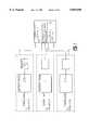
- FIG. 1is a block diagram schematic of a preferred embodiment of the present invention shown in a system environment
- FIG. 2is a block diagram schematic of a plurality of systems of FIG. 1, each connected to a central host computer, in accordance with another aspect of the present invention
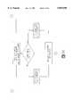
- FIG. 3is a block diagram schematic of a monitoring device used in the system of FIG. 1, shown connected to a piece of switchyard equipment;
- FIG. 4is a block diagram schematic of a communications node for use in the system of FIG. 1;
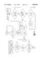
- FIGS. 5A and 5Btaken together, are a first flowchart for alarm events, as programmed into the monitoring device of FIG. 3;
- FIGS. 5C and 5Jtaken together, are a second flowchart for alarm events, as programmed into the monitoring device of FIG. 3;
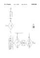
- FIG. 6is a schematic diagram of a circuit breaker configuration of FIG. 1;
- FIG. 7is a sample mechanism displacement plot generated by using data collected by the monitoring device of FIG. 3.
- FIG. 1is an overview of the system environment for the present invention.
- the present inventionis used for collecting and processing operating condition information and data from a plurality of pieces of switchyard equipment or gear.
- the operating informationis collected, stored, and analyzed to provide maintenance personnel with an operating history of the switchyard equipment such that preventive maintenance activities can be more efficiently scheduled, thereby resulting in reduced maintenance cost, increased availability, and extension of equipment service life.
- the switchyard equipmentmay be associated with a power distribution switchyard or an electric substation.
- Switchyard equipmentincludes circuit breakers, transformers, and the like.
- the circuit breakersare typically high-voltage, high-power gas or oil type breakers.
- the inventionis described in the context of a circuit breaker monitoring system, although the scope of the invention includes other types of switchyard equipment, including transformers, transmission and distribution circuits, capacitor banks and other power equipment.
- FIG. 1there is shown a plurality of three-phase circuit breakers 10, each connected to branches at an end of a power line 12.
- the other end of the power line 12is connected to a battery room 14 having a bank of batteries 16 and control equipment (not shown).
- the battery room 14outputs control voltage signals, typically at 125 or 250 VDC, which are carried by the power line 12 to the respective circuit breakers 10 for controlling the operation of the circuit breakers 10.
- the power line 12is also referred to as a local DC power bus.
- the bank of batteries 16are constantly trickle-charged by AC power. If AC power is disrupted, the batteries 16 allow the circuit breakers 10 to be controlled for a sufficient period of time before AC power is restored and the batteries 16 can be recharged.
- the power line 12is also used to communicate simple control status information from the circuit breakers 10 back to the control equipment in the battery room 14.
- Each switchyard locationincludes a plurality of the circuit breakers 10 and a battery room 14.
- the battery room 14is "remote” from the actual circuit breakers 10, it is in the same site or location as the circuit breakers 10.
- the above-described elements and system arrangementare conventional.
- the present inventioninterfaces with the above-described elements and system arrangement in a novel manner.
- FIG. 6illustrates a typical breaker configuration 19.
- the monitoring device 18is primarily a transmitter unit, but includes additional functions.
- the monitoring device 18interfaces with various sensors, provides data acquisition and limited data processing regarding breaker conditions, and provides communications with other components.
- Some types of data collected by the monitoring device 18include the following: time of fault initiation, if a fault occurs; current on each phase when the circuit breaker is operated; time of trip/close coil energization; time of arc extinction; ambient temperature in mechanism cabinet; accumulator air pressure; and gas pressure on compressor.
- each monitoring device 18is adapted to bidirectionally communicate with the other components via a power line carrier over the existing power line 12.
- the monitoring device 18itself is powered by the DC voltage on the power line 12.
- Another important feature of the inventionis that the monitoring device 18 is adapted to conduct comprehensive tests of switchyard equipment without the use of auxiliary test equipment, as required by the prior art.
- the monitoring device 18includes a built-in excitation voltage generator for use in testing a plural phase circuit breaker to obtain breaker response time. The monitoring device 18 is described in more detail below with respect to FIG. 3.
- the communications node 20is described in detail below with respect to FIG. 4.
- a remote host computer 22 located in a local breaker relay roomThe remote host computer 22 is connected to the communications node 20 and sends signals to, and receives signals from, the communications node 20.
- the connection between the remote host computer 22 and the communications node 20is an RS-232 link 23, or the like.
- the remote host computer 22receives data collected from the monitoring devices 18 and stores the data in a database 24 therein.
- the remote host computer 22further includes one or more application programs 26 and a display 28.
- the application programs 26process and analyze the data in the database 24 and create customized displays of breaker information from the data.
- one application program 26is a data analyzer for determining equipment performance, determining remaining life span of the equipment, and developing predictive maintenance schedules for the equipment.
- the remote host computer 22is a personal computer.
- the node computer 30is a portable or notebook personal computer which is used by breaker unit maintenance technicians to collect, analyze and display test mode data and historical operating data on a circuit breaker 10 under test.
- the node computer 30communicates with a monitoring device 18 through a direct RS-232 serial I/O port connection via an RS-232 link 32.
- the node computer 30thus receives data associated with the circuit breaker 10 connected to the respective monitoring device 18. More specifically, the node computer 30 receives local test data stored in the monitoring device 18.
- the node computer 30may also retrieve historical information for the respective circuit breaker 10 which was previously sent to the remote host computer 22 and which is currently stored in its database 24.
- the node computer 30retrieves the circuit breaker data from the database 24 via the power line 12.
- the node computer 30includes appropriate application programs (not shown) to perform these necessary functions.
- the node computer 30is not permanently attached to a monitoring device 18. Rather, it is moved from monitoring device 18 (or breaker location) to monitoring device 18 by the maintenance technician.
- the node computer 30may also interface directly with the remote host computer 22 in a similar manner.
- a central host computer 34located off-site.
- the central host computer 34communicates with the remote host computer 22 via a dial-up modem connection.
- the central host computer 34provides a centralized database 35 and processing functions for a plurality of set-ups, each set-up employing components (1)-(4).
- the central host computer 34includes application programs 58 and a display 60 for processing and analyzing the data in the centralized database 35 and creating customized displays of breaker information from the data.
- the application programs 58may be the same or more extensive than those in the remote host computer 22.
- Components (1)-(4)form a communication and data acquisition network.
- the power line 12 and RS-232 links 23 and 32are the communication paths in the network.
- the networkcommunicates between nodes. As described above, one node is located in the battery room at one end of the power line 12.
- each monitoring device 18is a node on the network. Accordingly, each monitoring device 18 includes appropriate communications node circuitry, as described below with respect to FIG. 3. In one embodiment of the invention, there are up to 254 monitoring devices 18 on a single network, and a single remote host computer 22 per network.
- FIG. 2shows a configuration wherein a central host computer 34 monitors a plurality of networks, each including the components (1)-(4).
- the host computer 34thus monitors a plurality of switchyard equipment sites 36 1 , 36 2 , . . . 36 n .
- FIG. 3shows a monitoring device 18 connected to a piece of switchyard equipment 38, which may be a circuit breaker, transformer, or the like.
- the monitoring device 18includes an I/O board 40, testing/monitoring circuitry 42, a storage device or memory 44, a processor 46, RS-232 port 47, and a node 48 for interfacing with the power line 12 (not shown).
- the I/O board 40accepts up to 16 analog and up to 24 digital input signals.
- the I/O board 40includes an A/D converter 70 connected to a high and a low speed multiplexer (MUX) 72 and 74 for processing the analog and digital signals.
- MUXlow speed multiplexer
- the high speed MUX 72processes signals described below which are received on high speed channels
- the low speed MUX 74processes signals described below which are received on low speed channels.
- the I/O board 40also outputs an analog excitation voltage and a DC test voltage, as needed. These output voltages may be used, for example, to test a solenoid or to test pressure sensors or contact closures.
- the analog outputuses a transformer isolated from the power line 12 and operating at 46 VDC.
- To test pressure sensors or contact closuresuses a transformer isolated from the power line 12 and operating at 10 VDC.
- the testing/monitoring circuitry 42includes the necessary hardware and software for performing the testing and monitoring of the switchyard equipment.
- the memory 44stores data acquired by the testing/monitoring circuitry 42. Periodically, the remote host computer 22 polls each monitoring device 18 for the data stored in the memory 44.
- the processor 46controls and coordinates the functions of the monitoring device 18.
- the processor 46houses software for processing trip event and close event data, and test software.
- the processor 46also houses software for processing alarm events, as described more fully with respect to FIGS. 5A-5D.
- the RS-232 port 47is used to interface with the node computer 30, as shown in FIG. 1.
- the node 48includes a transceiver (transmitter/receiver) 50 and a power line interface 52.
- the power line interface 52is connected at one end to the power line 12, and at the other end to the transceiver 50.
- the transceiver 50is a spread spectrum power line transceiver, and the data is transmitted to and from the remote host computer 22 via the power line 12 using a spread spectrum carrier.
- the transceiver 50uses spread spectrum carrier products available from Intellon Corporation, Ocala, Fla.
- the transceiver 50is an Intellon CENode PL which incorporates an Intellon CEThinx Network Controller and a CELinx pl Transceiver.
- the power line interface 52is a power line coupling circuit which is constructed using a transformer and capacitor, as set forth in Intellon's CENode PL Implementation Block Diagram.
- Each monitoring device 18has a unique 32-bit address, which is composed of an 8-bit Domain address, a 16-bit unit serial number, and an 8-bit node address.
- the 16-bit unit serial numberis contained in a read-only device and is unique to each monitoring unit 18.
- the monitoring unit 18operates from input supply voltages of either 125 or 250 VDC supplied by the power line 12.
- a 125/250 VDC switchis provided for selecting the appropriate input supply voltage.
- the data acquisition of analog signalsmay have the following features:
- FIG. 4shows the hardware associated with the communications node 20.
- the hardwareis essentially the same as the hardware of the node 48 in the monitoring device 18.
- the communications node 20includes a transceiver 54 and a power line interface 56 of similar construction as described above.
- the networkis patterned after the seven-layer OSI network model which includes a physical layer, data link, network layer, transport layer, session layer, presentation layer, and application layer.
- the physical layeris provided by the Intellon CEBus powerline carrier hardware with an appropriate interface to the 125/250 VDC power line 12.
- the data link and network layersare provided by the Intellon CEBus standard implementation.
- the transport and session layersare provided by custom software which uses the Intellon network layer facilities to define a series of acknowledged protocols for communicating messages between the remote host computer 22 and the monitoring devices 18.
- the presentation and application layersare provided by custom software that implements the acquisition, interpretation and storage of data.
- a communications node 20 and a remote host computer 22After a network of monitoring devices 18, a communications node 20 and a remote host computer 22 is installed and configured, communications between the remote host computer 22 and each monitoring device 18 are initiated. Communications occur by asynchronously polling each monitoring device 18 by the remote host computer 22. That is, a monitoring device 18 speaks to a remote host computer 22 only in response to a specific request by the remote host computer 22. A monitoring device 18 does not place any data packets on the network unless and until specifically requested to do so by the remote host computer 22. To achieve maximum network reliability, all message communications are acknowledged.
- the transport and session layer message protocolsare defined as follows:
- each monitoring device 18must be activated before it can begin to acquire data and be allowed to respond to requests for data from the remote host computer 22.
- the remote host computer 22activates a monitoring device 18 by sending it an ACTIVATE MESSAGE, and subsequently receiving an ACTIVATE ACKNOWLEDGE message therefrom. If the remote host computer 22 does not receive an acknowledge message from the monitoring device 18 within a specified period of time, another ACTIVATE message is sent. If no acknowledgement is received from the monitoring device 18 after a predetermined number of ACTIVATE messages have been sent, the remote host computer 22 generates an error message which is written to an error file in the remote host computer 22.
- the remote host computer 22activates all monitoring devices 18 on the network until each monitoring device 18 has been properly activated or until an error condition is generated for that monitoring device 18. As new monitoring devices 18 are added to the network, or defective monitoring devices 18 are replaced, the remote host computer 22 automatically activates them after the network configuration table (described below) has been manually updated.
- nnnnetwork address 8-bit (0-255)
- An eventis defined as a state transition involving either of the following operations:
- the beginning of a TRIP EVENTis defined as that instant of time at which the voltage across the trip solenoid coil reaches a predefined DC voltage threshold.
- the end of the trip eventis defined as that instant of time at which the current on all three phases (A, B and C) reads zero for at least five consecutive samples (e.g., 5 ms.).
- the beginning of a CLOSE EVENTis defined as that instant of time at which the voltage across the close solenoid coil reaches a predefined DC voltage threshold.
- the end of the close eventis defined as that instant of time at which the current on all three phases (A, B and C) has reached a value of at least three A/D counts (i.e., 23.4 amps).
- the remote host computer 22Upon completion of the activate sequence, the remote host computer 22 begins polling each monitoring device 18 to determine if an "event" has occurred. Possible event types are:
- An EVENT POLL MESSAGEis sent to each active monitoring device 18 on the network.
- a monitoring device 18receives an EVENT POLL MESSAGE, it sends an EVENT POLL ACKNOWLEDGE message back to the remote host computer 22.
- This acknowledge messagecontains a status word containing the following information:
- the remote host computer 22If the remote host computer 22 does not receive the EVENT POLL ACKNOWLEDGE message from a particular monitoring device 18 within a specified period of time, the remote host computer 22 proceeds to poll other monitoring devices 18 and picks up the unacknowledged monitoring device 18 on the next pass. This process does not present a problem since the event poll is conducted on a more or less continuous basis. If, however, a particular monitoring device 18 does not respond with an EVENT POLL ACKNOWLEDGE message after a predetermined number of event polls, then the remote host computer 22 generates an error entry in an ERROR FILE and sets the status of the particular monitoring device 18 to "error" in the network configuration table.
- the remote host computer 22When the remote host computer 22 encounters a monitoring device 18 that has events to report, it sends the monitoring device 18 a SEND EVENT DATA MESSAGE, requesting the monitoring device 18 to send the earliest event that it has stored. Upon receipt of the SEND EVENT DATA message, the monitoring device 18 sends the event data block to the remote host computer 22 and waits for an EVENT DATA ACKNOWLEDGE message back from the remote host computer 22. If the monitoring device 18 does not receive an acknowledgement from the remote host computer 22, the monitoring device 18 waits for another SEND EVENT DATA MESSAGE from the remote host computer 22. The monitoring device 18 does not flush any event data until it has received an acknowledgement from the remote host computer 22 indicating that the data has been successfully transferred.
- the communications protocol for event pollingmay be summarized as follows:
- the remote host computer 22conducts a Routine Poll sequence to retrieve routine data from each monitoring device 18.
- Each monitoring device 18is polled individually by the remote host computer 22 and asked to send its ROUTINE DATA BLOCK.
- the monitoring device 18Upon receipt of a SEND ROUTINE DATA MESSAGE from the remote host computer 22, the monitoring device 18 sends the routine data block to the remote host computer 22 and waits for a ROUTINE DATA ACKNOWLEDGE message back from the remote host computer 22. If the monitoring device 18 does not receive an acknowledgement from the remote host computer 22, it waits for another SEND ROUTINE DATA MESSAGE from the remote host computer 22.
- the monitoring device 18does not flush any routine data until it has received an acknowledgement from the remote host computer 22 indicating that the data has been successfully transferred. If a ROUTINE DATA BLOCK is not received from the monitoring device 18 within a specified period of time, the remote host computer 22 polls the next monitoring device 18 on the network until all monitoring devices 18 have been polled at least once. The remote host computer 22 then re-polls any monitoring device 18 from which no routine data has been received. The routine poll continues until routine data has been received from all monitoring devices 18.
- monitoring device 18 remote host computer 22If, however, a particular monitoring device 18 does not respond with a routine data block message after a predetermined number of routine polls, then the remote host computer 22 generates an error entry in the ERROR FILE and sets the status of the monitoring device 18 to "error" in the network configuration table.
- the communications protocol for routine pollingmay be summarized as follows: monitoring device 18 remote host computer 22
- a monitoring device 18enters the Test Mode in response to a command from a node computer 30 (typically operated by a maintenance technician) connected to the monitoring unit's local RS-232 port. However, the Test Mode is not entered if there is unread event data in the monitoring device 18. All event data must be uploaded to the remote host computer 22 before the Test Mode is entered. Upon entering the Test Mode, the monitoring device 18 sets a flag in the next EVENT POLL ACKNOWLEDGE message that it sends back to the remote host computer 22, thus notifying the remote host computer 22 that the monitoring device 18 is in the Test Mode. The monitoring device 18 also suspends accumulation of routine data.
- the remote host computer 22Upon detecting the Test Mode flag for a particular monitoring device 18, the remote host computer 22 immediately conducts a routine poll of that monitoring device 18 to collect any remaining routine data accumulated since the last routine poll. The remote host computer 22 continues to send EVENT POLL messages to the monitoring device 18 in the Test Mode. As long as the monitoring device 18 is in a Test Mode, it responds to EVENT POLL messages by indicating that it is "busy"(i.e., in the Test Mode).
- Test eventsare sent to the remote host computer 22 in the same manner as event data, except that the communications are tagged as TEST EVENTS.
- the node computer 30is adapted to access information from the database 24 of the remote host computer 22 by sending requests through the monitoring device 18 to the remote host computer 22, via the power line 12.
- the database requests and responses theretoare communicated through the nodes 20 and 48 using the spread spectrum power line transceivers 50 and 54 and spread spectrum carrier described above.
- the database request from the node computer 30causes a flag to be set in the EVENT POLL ACKNOWLEDGE status word.
- the remote host computer 22then polls the monitoring device 18 to ask what specific data is desired, using a SEND DATABASE QUERY message.
- the monitoring device 18responds with a DATABASE QUERY MESSAGE which specifies the database records desired.
- the remote host computer 22sends the DATABASE INFORMATION (which may comprise a number of data packets), and then waits for a DATABASE ACKNOWLEDGE message from the monitoring device 18, verifying that the DATABASE INFORMATION message was correctly received.
- the Test Modeis exited by issuing a command at the node computer 30, which is passed on to the monitoring device 18. If the monitoring device 18 has successfully uploaded all test data to the remote host computer 22, the test data memory is flushed before returning to the routine poll mode. Next, the monitoring device 18 clears the Test Mode flag in the Event Poll acknowledge status word, and resumes collection of routine data. The remote host computer 22 then updates the monitoring device 18 mode to "routine" in the network configuration table, and routine polling of the monitoring device 18 resumes at the next hourly poll.
- the communications protocol for the Test Modemay be summarized as follows:
- the maintenance technicianruns application programs in the node computer 30 to obtain immediate feedback regarding the switchyard equipment.
- the node computer 30is also used to access historical data from the database 24 of remote host computer 22, as described above.
- the node computer 30compares the new test data with the historical data to set new alarm thresholds and baselines for the particular piece of switchyard equipment. A specific example of how test data is generated and used when rebuilding a breaker is provided below.
- Routine DataNo events to report.
- the monitoring device 18Upon receiving a SEND ROUTINE DATA MESSAGE from the remote host computer 22 (that it is the top of the hour), the monitoring device 18 computes and stores averaged values of temperature and pressure, and the accumulated amp-hours for each phase since the last routine poll. Next, the monitoring device 18 sends this information to the remote host computer 22 as a ROUTINE DATA BLOCK. The remote host computer 22 then stores this information in the ROUTINE FILE which is subsequently read by the database manager and incorporated into the database 24.
- the structure of the ROUTINE DATA BLOCKis as follows:
- Trip EventDefined as the instant in time at which the voltage across the trip solenoid reaches a preset threshold and ending at the instance in time at which the current on all three phases (A, B and C) has read zero for 5 consecutive samples (i.e., 5 ms).
- the EVENT DATA BLOCK structure for a Trip Eventis as follows:
- the EVENT DATA BLOCK structure for a Close Eventis as follows:
- Compressor EventDefined as the instant in time at which a running average of 5 sec. slope exceeds (+). and ending at the instant in time at which a running average of 5 sec. slope is less than or equal to (+).
- the EVENT DATA BLOCK structure for a Compressor Eventis as follows:
- Test Trip EventIn the Test Mode, a Test Trip Event is defined as the instant in time at which the voltage across the close solenoid reaches a preset threshold, and ending at the instant in time at which the current on all three phases (A, B and C) has reached a value of (p+-3 a/d counts) for at least 5 consecutive samples (i.e. 5 ms).
- Test Trip eventThe data structure for the Test Trip event is identical to that for the Test Close event described below.
- Test Close EventIn the transmitter Test Mode a Test Close Event is defined as the instant in time at which the voltage across the close solenoid reaches a preset threshold, and ending at the instant in time at which the current on all three phases (A, B and C) has reached a value of at least 23 amps (3 a/d counts).
- the monitoring device 18includes data link and network software, as well as application software.
- the data link and network softwareis based on Intellon's CEBus packet communications facilities.
- the data link layers and network layershandle the communication of data packets between the remote host computer 22 and the monitoring device 18 over the network communications media (power line 12).
- the application softwareis written in the C programming language, with some time critical routines written in the native assembly language of the monitoring device processor 46.
- the application softwareprovides data acquisition/storage, packet construction and parsing, messaging protocols, and monitoring unit executive functions.
- the remote host computer 22comprises appropriately configured Intel processor-based PC hardware, Microsoft Windows NT Workstation system software, network control and data collection software, and various database management and application software functions.
- the network control and data collection softwareprovides (a) all communications with the monitoring devices 18 on the network, (b) data collection functions, and (c) interfacing with the database application software.
- the network control and data collection softwarealso collects breaker operating, event and test data from the monitoring devices 18, and presents the data to the database application software via the following files on a hard disk of the remote host computer 22:
- Routine Data File--contains routine operating data for each active monitoring device 18 on the network.
- Event Data File--contains operating event data (trip, close, compressor) from any monitoring device 18 on which an operating event occurred.
- Test Data File--contains test event data from any breaker undergoing test or maintenance.
- the network control and data collection softwarefacilitates requests by a node computer 30 for transmission of information stored in the database 24 of the remote host computer 22 to a monitoring device 18.
- the node computer 30comprises appropriately configured portable notebook computer hardware, Microsoft Windows 3.1, Windows for Workgroups 3.11, or Windows 95 operating system software, software for interfacing with a monitoring device 18, and test applications support software.
- the interface softwareenables communications of commands and data between the monitoring device 18 and the node computer test applications software, via an RS-232 direct connection between the monitoring device 18 and node computer 30.
- the interface softwarehas a foreground process to allow connection to the monitoring device 18 and downloading of set-up information, and a background process to allow the test applications support software to read test data from the monitoring device 18 and request/receive database information from the remote host computer 22.
- a software program for implementing the flowchartis programmed into one or more EPROMs in the processor 46 of the monitoring device 18.
- the alarms in FIGS. 5A-5Dare front-end alarms which are proactively transmitted by the monitoring device 18 when triggered. That is, the monitoring device 18 does not wait for a polling signal from the remote host computer 22 or central host computer 34 to send the alarm event. Examples of these alarms were described above in the section entitled "Transmitter Routine and Event Data Block Structures".
- Variablessuch as thresholds, which are required for performing the steps in the flowcharts of FIGS. 5A-5D are pre-programmed into the EPROM(s) of the processor 46 when the monitoring device 18 is installed.
- the thresholdsmay be viewed and/or reprogrammed through a node computer 30 when a maintenance technician services the switchyard equipment.
- the application programs resident in the remote host computer 22 and central host computer 34generate back-end alarms after processing data received from the monitoring device 18, and storing the processed data in the databases of the computers 22 and 34.
- the back-end alarmsare typically less critical than the front-end alarms generated directly by the monitoring device 18.
- FIG. 6shows a schematic diagram of one circuit breaker installation 19 in FIG. 1.
- the particular circuit breaker installation illustrated hereincomprises a conventional oil circuit breaker 62 having three tanks, poles or phases A, B, C. Each phase has a line side 64 and a load side 66. Each phase is controlled by a breaker mechanism 68.
- the mechanism 68includes a piston 76 for tripping/closing each of the three phases.
- the novel monitoring device 18 of the present inventionis physically bolted to the housing of the breaker mechanism 68. Electrical interconnections between the monitoring device 18 and the circuit breaker 62 are not shown in detail.
- output leads and cablesare attached to the monitoring device 18 and connected to respective parts of the breaker 62.
- one output leadis connected to a transducer or sensor 78 for measuring displacement of the piston 76 and/or for measuring displacement of contact closure mechanisms 79 inside each phase.
- Each phaseincludes a test tap for connection of the sensor 78 thereto.
- the sensor(s) 78may be any prior art sensor suitable for such purposes.
- a multi-line output cableis connected at one set of ends to the isolated excitation voltage output of the monitoring device 18, and at the other set of ends to the line and load sides of the breaker phases A-C. The output leads and cables are removed after exiting the Test Mode.
- the node computer 30, in conjunction with testing capabilities built into the monitoring device 18,allows a maintenance technician to test a piece of switchyard equipment, compare the test data to historical data, set new alarm thresholds (i.e., values in the EPROM(s) of processor 46), and set new baselines stored in the remote host computer 22. Baselines are used by the remote host computer 22 to determine when subsequent event data indicates potential problems or wear in the switchyard equipment. This feature is particularly useful when rebuilding switchyard equipment.
- the monitoring device 18may be configured as shown in FIG. 6 to test a plural phase circuit breaker and obtain breaker response time when rebuilding a breaker. After the breaker 62 is rebuilt, the node computer 30 is connected to the monitoring device 18 and the Test Mode is entered.
- the leads and cablesare connected to the sensor(s) 78 and the line and load sides of the breaker phases A-C.
- the isolated excitation voltageis applied from the monitoring device 18 and the monitoring device 18 receives test trip event and test close event data from the breaker 62, as well as piston displacement data (i.e., breaker mechanism movement).
- the piston displacement datais the "piston displacement sample set" referred to above which is obtained during the test trip event and test close event. Typically, plural tests (such as eight or more) are conducted.
- the collected datais downloaded into the node computer 30.
- An application program in the node computer 30creates mechanism displacement plots (trend curves) from the data. Each of the plural tests generates a plot. That is, a plot is generated for each trip and close test cycle. A sample plot is shown in FIG. 7.
- the maintenance technicianreviews the plots and selects which plots are to be used to generate an averaged plot. Typically, four plots are selected.
- the node computer 30causes the monitoring device 18 to keep the data associated with the four selected plots and to discard data associated with unselected plots. If desired, the maintenance technician compares the current averaged plot with an averaged plot generated from the previous Test Mode (i.e., historical data). To perform a current vs.
- the historical datais downloaded to the node computer 30 from the remote host computer 22 in response to a request for data sent by the node computer 30 (through the monitoring device 18) to the remote host computer 22.
- the maintenance technicianuses the information in the plots to set new alarm thresholds and baselines for the breaker 62.
- the monitoring device 18sends the new data associated with the four selected plots to the remote host computer 22 for storage therein and for use in setting new baselines. The new plot data will also be used for comparison purposes during the next breaker rebuild.
- One or more of the application programs 26 which are resident in the remote host computer 22may also be resident in the node computer 30. In this manner, a maintenance technician in the field can retrieve data from the database 24 of the remote host computer 22 and perform local analysis and display of information regarding the switchyard equipment 10.
- the application programs in the node computer 30, remote host computer 22 and central host computer 34are identical.
- the node computer 30may be directly connected to the remote host computer 22.
- the node computer 30can then run application programs 26 which are stored therein using the data in the database 24, but which are not available in the remote host computer 22.
- the remote host computer 22polls the monitoring devices 18 for new data about once per second, and the central host computer 34 polls the remote host computer 22 for new data about once every half hour or hour.
- the polling frequenciesmay be greater or less than these values.
Landscapes
- Engineering & Computer Science (AREA)
- Power Engineering (AREA)
- Remote Monitoring And Control Of Power-Distribution Networks (AREA)
Abstract
Description
______________________________________No. of Channels: 16 (6 high speed, 8 low speed)Resolution: 8 bitsSample Rate: 1 ms, for high speed channels (8 channels sampled simultaneously) 1 second, for low speed channels (8 channels sampled simultaneously)Sample Clock Frequency: High Speed: 1 KHZ (1 ms period) Low Speed: 1 Hz (1 second period)Analog Input Signals:(RTD) Ambient Air -39 to +122° C.TemperatureSensor voltage output: TBD(CT1) Current Transformer, 0-100 mv RMS (0 to 2000 amps)Phase ASensor voltage output:(CT2) Current Transformer, 0-100 mv RMS (0 to 2000 amps)Phase BSensor voltage output:(CT3) Current Transformer, 0-100 mv RMS (o to 2000 amps)Phase CSensor voltage output:(P1) Pressure No. 1 0-100 mv(P2) Pressure No. 2 0-100 mv(optional)(TRIP) Solenoid VoltageVoltage: 125 VDC 250 VDC(CLOSE) Close SolenoidVoltageVoltage: 125 or 250 VDC(PD) Piston DisplacementVoltage: 1-5 voltsTest Mode DC voltagePhase A 0-100 VDCTest Mode DC voltagePhase B 0-100 VDCTest Mode DC voltagePhase C 0-100 VDCLow Speed Channels: RTD Ambient air Temperature CT1 Current Transformer phase A CT2 Current Transformer phase B CT3 Current Transformer phase C P1 Pressure No. 1 P2 Pressure No. 2High Speed Channels: CT1 Current Transformer phase A CT2 Current Transformer phase B CT3 Current Transformer phase C Piston Displacement Voltage Test Mode DC voltage phase A Test Mode DC voltage phase B Test Mode DC voltage phase CContact Closure Inputs:No. of lines: 24Type: Dry contactExcitation voltage: +10 VDC(supplied by transmitter)______________________________________
______________________________________Closed to Open (Trip Event)Open to Closed (Close Event)______________________________________
__________________________________________________________________________monitoringdevice 18remote host computer 22__________________________________________________________________________ <<<< EVENT POLL MESSAGEEVENT POLL ACKNOWLEDGE >>>>(if events to report, then) <<<< SEND EVENT DATA MESSAGEEVENT DATA BLOCK >>>> <<<< EVENT DATA ACKNOWLEDGE__________________________________________________________________________
__________________________________________________________________________monitoringdevice 18remote host computer 22__________________________________________________________________________ <<<< SEND ROUTINE DATA MESSAGEROUTINE DATA BLOCK >>>> <<<< ROUTINE DATA ACKNOWLEDGE__________________________________________________________________________
__________________________________________________________________________monitoringdevice 18remote host computer 22__________________________________________________________________________ <<<< EVENT POLL MESSAGEEVENT POLL ACKNOWLEDGE >>>>(with Test Mode flag set) <<<< SEND ROUTINE DATA MESSAGEROUTINE DATA BLOCK >>>> <<<< ROUTINE DATA ACKNOWLEDGE<<<< EVENT POLL MESSAGES and ACKNOWLEDGES >>>>(if test events to report, then) <<<< SEND TEST EVENT DATA MESSAGETEST EVENT DATA BLOCK >>>> <<<< TEST EVENT DATA ACKNOWLEDGE<<<< EVENT POLL MESSAGES and ACKNOWLEDGES >>>>(if database query request, then) <<<< SEND DATABASE QUERYDATABASE QUERY MESSAGE >>>> <<<< DATABASE INFORMATIONDATABASE ACKNOWLEDGE >>>>(to exit test mode) <<<< EVENT POLL MESSAGEEVENT POLL ACKNOWLEDGE >>>>(with Test Mode flag cleared)__________________________________________________________________________
______________________________________(2 byte) Routine Status word (0-65535) Bit-Mapped value for Routine status indicators(1 byte) Temperature (0-255 counts)(1 byte) #1 Tank Pressure (0-255 counts)(1 byte) #2 Tank Pressure (0-255 counts)(3 byte) Phase A Amp-Hours (0-1.7 Ma)(3 byte) Phase B Amp-Hours (0-1.7 Ma)(3 byte) Phase C Amp-Hours (0-1.7 Ma)14 bytes total______________________________________Routine StatusBit # Definition______________________________________0 (LSB) 0-Routine Mode 1 -Test Mode 1 Data Block Type: 001-Routine 2 010-Trip Event 3 011-Close Event 100-Test Trip Event 101-Test Close Event 111-Compressor Event 4Hi Temperature Alarm 5 Lo Temperature Alarm6 #1 Compressor On7 #1 TankLo Pressure Alarm 8 #1 Tank Hi Pressure Alarm9 #2 Compressor On10 #2 Tank Lo Pressure Alarm11 #2 Tank Hi Pressure Alarm______________________________________
______________________________________(2 byte) Event Status (0-65535) Bit-Mapped value forword Event status indicators (see Trip/Close Status below)(1 byte) Event counter (0-255) Stored events in monitoring device 18 from previous poll(2 byte) Events since last (0-65535) Total events since last Test maintenance test(1 byte) Total Event Time (0-255 ms) Total time of event from start to finish(1 byte) Phase A-B Delay (0-255 ms) Time difference between Time phase A & B reaching 0 value(1 byte) Phase A-C Delay (0-255 ms) Time difference between Time phase A & C reaching 0 value(1 byte) Phase B-C Delay (0-255 ms) Time difference between Time phase B & C reaching 0 value(2 byte) Phase A Current (0-65535) Instantaneous current value on Phase A at Start time(2 byte) Phase B Current (0-65535) Instantaneous current value on Phase B at Start time(2 byte) Phase C Current (0-65535) Instantaneous current value on Phase C at Start time(1 byte) #1 Tank Pressure (0-255 counts) Tank #1 pressure at Event start time(1 byte) #2 Tank Pressure (0-255 counts) Tank #2 pressure at Event start time (0 if N/A)(1 byte) Event Temperature (0-255 counts) Temperature at Event start time(3 byte) Event Age (0-194 days) Elapsed seconds since the Event start time21 bytes total______________________________________
______________________________________(2 byte) Trip/Close Event (0-65535) Bit-Mapped value for Status Event status indicators (see Trip/Close Status below)(1 byte) Event counter (0-255) Stored events in monitoring device 18 from previous poll(2 byte) Events since last (0-65535) Total events since last Test maintenance test(1 byte) Total Event Time (0-255 ms) Total time of event from start to finish(1 byte) Phase A-B Delay (0-255 ms) Time difference between Time phase A & B × ms after Event Start(1 byte) Phase A-C Delay (0-255 ms) Time difference between Time phase A & C × ms after Event Start(1 byte) Phase B-C Delay (0-255 ms) Time difference between Time phase B & C × ms after Event Start(2 byte) Phase A Current (0-65535) Instantaneous current value on Phase A at Finish time(2 byte) Phase B Current (0-65535) Instantaneous current value on Phase B at Finish time(2 byte) Phase C Current (0-65535) Instantaneous current value on Phase C at Finish time(1 byte) #1 Tank Pressure (0-255 counts) Tank #1 pressure at Event start time(1 byte) #2 Tank Pressure (0-255 counts) Tank #2 pressure at Event start time (0 if N/A)(1 byte) Event Temperature (0-255 counts) Temperature at Event start time(3 byte) Event Age (0-194 days) Elapsed seconds since the Event start time21 bytes total______________________________________Routine StatusBit # Definition______________________________________0 (LSB) 0-Routine Mode 1 - Test Mode1 Data Block Type: 001-Routine2 010-Trip Event3 011-Close Event 100-Test Trip Event 101-Test Close Event 111-Compressor Event4 Hi Temperature Alarm5 #1 Tank Compressor On6 #1 Tank Lo Pressure Alarm7 #1 Tank Hi Pressure Alarm8 #2 Tank Compressor On9 #2 Tank Lo Pressure Alarm10 #2 Tank Hi Pressure Alarm11 Maximum event time exceeded12 Phase A-B maximum (open/close) delay time exceeded13 Phase A-C maximum (open/close) delay time exceeded14 Phase B-C maximum (open/close) delay time exceeded______________________________________
______________________________________(2 byte) Compressor Event (0-65535) Bit-Mapped value for Status Event status indicators(1 byte) Event counter (0-255) Stored events inmonitoring device 18 from previous poll(2 byte) Events since last (0-65535) Accumulative Charge Test cycles since last maintenance test(2 byte) Total Run Time (0-65535 sec) Total Compressor run time from start to finish(1 byte) Event Temperature (0-255 counts) Temperature at Event start time(3 byte) Event Age (0-194 days) Elapsed seconds since event start time11 bytes total______________________________________Compressor Event StatusBit # Definition______________________________________0 (LSB) 0-Routine Mode 1 -Test Mode 1 Data Block Type: 001-Routine 2 010-Trip Event 3 011-Close Event 100-Test Trip Event 101-Test Close Event 111-Compressor Event 4 0-#1 Compressor Event 1-#2Compressor Event 5 Hi Temperature Alarm6Lo Temperature Alarm 7 Tank Compressor On8 Tank Lo Pressure Alarm9 TankHi Pressure Alarm 10 Maximum Run-Time Exceeded______________________________________
______________________________________(2 byte) Event Status Word (0-65535) Bit-Mapped value for Event status indicators (see Trip/Close Status below)(1 byte) Total Event Time (0-255 ms) Total time for all phases to reach final value(1 byte) Phase A Event (0-255 ms) Total time of phase A Time Event from Start to Finish(1 byte) Phase B Event (0-255 ms) Total time of phase B Time Event from Start to Finish(1 byte) Phase C Event (0-255 ms) Total time of phase C Time Event from Start to Finish(320 Phase A voltage (0-255 counts) Sampled data set forbytes) sample set Phase A Event(320 Phase B voltage (0-255 counts) Sampled data set forbytes) sample set Phase B Event(320 Phase C voltage (0-255 counts) Sampled data set forbytes) sample set Phase C Event(1 byte) Phase A-B Delay (0-255 counts) Time difference between Time phase A & B final values(1 byte) Phase A Finish (0-255 counts) Sample # in sampled sample # data for Finish of Phase A Event(1 byte) Phase A-C Delay (0-255 counts) Time difference between Time phase A & C final values(1 byte) Phase B Finish (0-255 counts) Sample # in sampled sample # data for Finish of Phase B Event(1 byte) Phase B-C Delay (0-255 counts) Time difference between Time phase B & C final values(1 byte) Phase C Finish (0-255 counts) Sample # in sampled sample # data for Finish of Phase C Event(320 Piston displace- (0-255 counts) Sampled data set forbytes) ment sample set Piston displacement during Event(1 byte) Event Temperature (0-255 counts) Temperature at Event Start time(1 byte) #1 Tank Pressure (0-255 counts) Tank #1 pressure at Event start time(1 byte) #2 Tank Pressure (0-255 counts) Tank #2 pressure at Event start time if applicable1295 totalbytes______________________________________
Claims (6)
Priority Applications (1)
| Application Number | Priority Date | Filing Date | Title |
|---|---|---|---|
| US08/705,395US5859596A (en) | 1996-08-30 | 1996-08-30 | Switchyard equipment monitoring system and communications network therefor |
Applications Claiming Priority (1)
| Application Number | Priority Date | Filing Date | Title |
|---|---|---|---|
| US08/705,395US5859596A (en) | 1996-08-30 | 1996-08-30 | Switchyard equipment monitoring system and communications network therefor |
Publications (1)
| Publication Number | Publication Date |
|---|---|
| US5859596Atrue US5859596A (en) | 1999-01-12 |
Family
ID=24833272
Family Applications (1)
| Application Number | Title | Priority Date | Filing Date |
|---|---|---|---|
| US08/705,395Expired - LifetimeUS5859596A (en) | 1996-08-30 | 1996-08-30 | Switchyard equipment monitoring system and communications network therefor |
Country Status (1)
| Country | Link |
|---|---|
| US (1) | US5859596A (en) |
Cited By (67)
| Publication number | Priority date | Publication date | Assignee | Title |
|---|---|---|---|---|
| US6121593A (en)* | 1998-08-19 | 2000-09-19 | Duck Creek Energy, Inc. | Home appliances provided with control systems which may be actuated from a remote location |
| US6246928B1 (en)* | 1997-12-09 | 2001-06-12 | Schneider Electric Sa | Electrical interruption device comprising a communication module |
| WO2002054562A1 (en)* | 2000-12-29 | 2002-07-11 | Abb Ab | Substation control system |
| US6466023B2 (en)* | 1998-12-28 | 2002-10-15 | General Electric Company | Method of determining contact wear in a trip unit |
| US6473608B1 (en) | 1999-01-12 | 2002-10-29 | Powerdsine Ltd. | Structure cabling system |
| US20020194406A1 (en)* | 2001-06-18 | 2002-12-19 | Houlberg Christian Lauritz | RS-232 bus data tap apparatus |
| US6502203B2 (en)* | 1999-04-16 | 2002-12-31 | Compaq Information Technologies Group, L.P. | Method and apparatus for cluster system operation |
| US20030099076A1 (en)* | 1999-08-02 | 2003-05-29 | Shimon Elkayam | Integral board and module for power over LAN |
| US6665720B1 (en)* | 1999-09-21 | 2003-12-16 | Intel Corporation | Adapter for a home power line network |
| US6694270B2 (en) | 1994-12-30 | 2004-02-17 | Power Measurement Ltd. | Phasor transducer apparatus and system for protection, control, and management of electricity distribution systems |
| US20040037300A1 (en)* | 1999-01-12 | 2004-02-26 | Amir Lehr | Structure cabling system |
| US20040049321A1 (en)* | 1999-01-12 | 2004-03-11 | Amir Lehr | System for power delivery over data communication cabling infrastructure |
| US20040062203A1 (en)* | 1998-04-10 | 2004-04-01 | Austermann John F. | System for communicating with electronic equipment |
| US20040104784A1 (en)* | 2002-11-19 | 2004-06-03 | Ishmael Enriquez | Wide area network as applied to switchyard/substation control design |
| US20040153779A1 (en)* | 2001-03-20 | 2004-08-05 | Sven Laurosch | Switchgear cabinet or switchgear cabinet assembly comprising a monitoring device that is arranged therein |
| US20040189307A1 (en)* | 2003-03-31 | 2004-09-30 | Rudholm Stig Olov | Methods and apparatus for analyzing high voltage circuit breakers |
| US20040204075A1 (en)* | 2002-05-29 | 2004-10-14 | Rusnak Mark Frederick | Wireless transceiver module and system employing a wireless transceiver apparatus between a portable communicating device and a communication network |
| US20040261626A1 (en)* | 2002-03-26 | 2004-12-30 | Tmio, Llc | Home appliances provided with control systems which may be actuated from a remote location |
| US20050025162A1 (en)* | 2002-11-13 | 2005-02-03 | Yehuda Binder | Addressable outlet, and a network using same |
| US20050040809A1 (en)* | 2003-08-22 | 2005-02-24 | Uber Arthur E. | Power line property measurement devices and power line fault location methods, devices and systems |
| US20050231320A1 (en)* | 2004-04-20 | 2005-10-20 | Ackermann John M | Wireless communication fuse state indicator system and method |
| US20050254494A1 (en)* | 2000-09-21 | 2005-11-17 | Serconet, Ltd. | Telephone communication system and method over local area network wiring |
| WO2006014691A1 (en)* | 2004-07-21 | 2006-02-09 | Underground Systems, Inc. | Dynamic line rating system with real-time tracking of conductor creep to establish the maximum allowable conductor loading as limited by clearance |
| US20060077607A1 (en)* | 2004-09-10 | 2006-04-13 | Henricks Michael C | Circuit protector monitoring assembly kit and method |
| US20060087397A1 (en)* | 2004-10-26 | 2006-04-27 | Cooper Technologies Company | Fuse state indicating optical circuit and system |
| US20060092962A1 (en)* | 1998-07-28 | 2006-05-04 | Serconet, Ltd | Local area network of serial intelligent cells |
| US20060176630A1 (en)* | 2005-02-09 | 2006-08-10 | Eaton Corporation | System for wireless monitoring of circuit breakers |
| US20060181427A1 (en)* | 2005-01-31 | 2006-08-17 | Csi Technology, Inc. | Machine condition indication system |
| US20060209847A1 (en)* | 1999-07-07 | 2006-09-21 | Serconet, Ltd. | Local area network for distributing data communication, sensing and control signals |
| US20060235741A1 (en)* | 2005-04-18 | 2006-10-19 | Dataforensics, Llc | Systems and methods for monitoring and reporting |
| US20070143207A1 (en)* | 2005-12-16 | 2007-06-21 | Breen Thomas B | Method and system for lease of assets, such as trailers, storage devices and facilities |
| US20070194942A1 (en)* | 2004-09-10 | 2007-08-23 | Darr Matthew R | Circuit protector monitoring assembly, system and method |
| US20070257807A1 (en)* | 2004-09-10 | 2007-11-08 | Darr Matthew R | Circuit protector monitoring assembly |
| US20080114998A1 (en)* | 2006-11-12 | 2008-05-15 | Microsemi Corp. - Analog Mixed Signal Group Ltd. | Reduced Guard Band for Power Over Ethernet |
| US20080225453A1 (en)* | 2007-03-16 | 2008-09-18 | Hansder Engineering Co., Ltd. | Breaker control system using power frequency carrier |
| US20080231410A1 (en)* | 2004-04-20 | 2008-09-25 | Frank Anthony Doljack | RFID Open Fuse Indicator, System, and Method |
| US20090132679A1 (en)* | 2004-01-13 | 2009-05-21 | Serconet, Ltd. | Information device |
| US20090259507A1 (en)* | 2005-09-30 | 2009-10-15 | Hirobumi Miwa | Working Machine Maintenance Work Management System |
| US20090282274A1 (en)* | 2008-05-09 | 2009-11-12 | International Business Machines Corporation | Managing Power Consumption In A Data Center |
| US20090287943A1 (en)* | 2008-05-15 | 2009-11-19 | International Business Machines Corporation | Mapping power domains in a data center |
| US20090296712A1 (en)* | 2008-05-27 | 2009-12-03 | Eyran Lida | Methods and devices for cec block termination |
| US20100030392A1 (en)* | 2008-07-31 | 2010-02-04 | Microsemi Corp. - Analog Mixed Signal Group Ltd. | Time Integrated Guard Band |
| US20100115299A1 (en)* | 2008-11-04 | 2010-05-06 | Microsemi Corp. - Analog Mixed Signal Group, Ltd. | Compensation for high powered midspan power sourcing equipment |
| US20100123453A1 (en)* | 2008-11-19 | 2010-05-20 | Nokomis, Inc. | Advance manufacturing monitoring and diagnostic tool |
| US20100164749A1 (en)* | 2008-12-29 | 2010-07-01 | Power Measurement Ltd. | Automatic Registration of Meters to a Centralized Data System |
| US7808128B1 (en)* | 2004-11-12 | 2010-10-05 | Dgi Creations, Llc | Remote monitoring of control decisions for network protectors |
| CN101867225A (en)* | 2010-05-31 | 2010-10-20 | 江苏省电力公司南通供电公司 | Integrated debugging method for substation comprehensive automation and relay protection system |
| US8350417B1 (en)* | 2007-01-30 | 2013-01-08 | Sunpower Corporation | Method and apparatus for monitoring energy consumption of a customer structure |
| US8363797B2 (en) | 2000-03-20 | 2013-01-29 | Mosaid Technologies Incorporated | Telephone outlet for implementing a local area network over telephone lines and a local area network using such outlets |
| CN103197233A (en)* | 2012-12-18 | 2013-07-10 | 辽宁省电力有限公司检修分公司 | High-voltage switch opening and closing time online monitor and high-voltage switch opening and closing time online monitoring method |
| US8860353B1 (en) | 2011-04-22 | 2014-10-14 | Dgi Creations, Llc | Protection for a network protector close motor |
| US8873586B2 (en) | 2000-04-19 | 2014-10-28 | Conversant Intellectual Property Management Incorporated | Network combining wired and non-wired segments |
| US9217775B2 (en) | 2010-06-07 | 2015-12-22 | Abb Research Ltd. | Systems and methods for characterizing fault clearing devices |
| WO2015192659A1 (en)* | 2014-06-19 | 2015-12-23 | 国家电网公司 | Intelligent transformer substation warning message reporting method |
| US20160364975A1 (en)* | 2015-06-10 | 2016-12-15 | Alstom Transport Technologies | Equipment life span monitoring system and method |
| CN106663963A (en)* | 2015-05-06 | 2017-05-10 | 杨启蓓 | Smart multi-dimensional big data analyzing expert system for high-voltage circuit breaker in power grid |
| JP2018201331A (en)* | 2014-03-07 | 2018-12-20 | 株式会社Gsユアサ | Maintenance and operation system for apparatus with storage battery |
| US10205307B2 (en) | 2010-03-23 | 2019-02-12 | Southwire Company, Llc | Power line maintenance monitoring |
| US10448864B1 (en) | 2017-02-24 | 2019-10-22 | Nokomis, Inc. | Apparatus and method to identify and measure gas concentrations |
| US10890345B2 (en)* | 2017-08-09 | 2021-01-12 | Verdigris Technologies, Inc. | System and methods for a commissioning a sensor system |
| WO2021168265A1 (en) | 2020-02-21 | 2021-08-26 | Schneider Electric USA, Inc. | Circuit breakers with field servicing capability |
| CN113364129A (en)* | 2021-06-25 | 2021-09-07 | 广西电网有限责任公司 | High-availability method for data processing service of power grid monitoring system |
| DE102020209645A1 (en) | 2020-07-30 | 2022-02-03 | Siemens Aktiengesellschaft | Method for determining the status of an electrical switchgear, monitoring unit for an electrical switchgear and electrical switchgear |
| US11402423B2 (en)* | 2016-12-05 | 2022-08-02 | Siemens Energy Global GmbH & Co. KG | Operating component |
| US11489847B1 (en) | 2018-02-14 | 2022-11-01 | Nokomis, Inc. | System and method for physically detecting, identifying, and diagnosing medical electronic devices connectable to a network |
| US20230058294A1 (en)* | 2021-08-20 | 2023-02-23 | Alabama Power Company | Condition-based circuit breaker maintenance arrangement for electrical power distribution infrastructure |
| US12445461B2 (en) | 2022-10-13 | 2025-10-14 | Nokomis, Inc. | System and method for physically detecting, identifying, and diagnosing medical electronic devices connectable to a network |
Citations (9)
| Publication number | Priority date | Publication date | Assignee | Title |
|---|---|---|---|---|
| US5179376A (en)* | 1991-02-28 | 1993-01-12 | Systems Analysis And Integration, Inc. | Substation load distribution monitor system |
| US5270658A (en)* | 1991-08-19 | 1993-12-14 | Epstein Barry M | Means and method for testing and monitoring a circuit breaker panel assembly |
| US5301122A (en)* | 1992-02-12 | 1994-04-05 | Measuring And Monitoring, Inc. | Measuring and monitoring system |
| US5384678A (en)* | 1992-06-09 | 1995-01-24 | Gec Alsthom T & D Sa | Control and self-monitoring system, in particular for a multipole electrical apparatus such as a high tension circuit breaker |
| US5490086A (en)* | 1992-03-06 | 1996-02-06 | Siemens Energy & Automation, Inc. | Plug-in ground fault monitor for a circuit breaker |
| US5491463A (en)* | 1993-06-28 | 1996-02-13 | Advanced Control Technologies, Inc. | Power line communication system |
| US5502435A (en)* | 1994-04-06 | 1996-03-26 | Ralston; Douglas E. | Method and system for monitoring circuit breaker gas pressure |
| US5554968A (en)* | 1994-08-22 | 1996-09-10 | Lee; Raymond | Data communication using power lines |
| US5694108A (en)* | 1996-05-01 | 1997-12-02 | Abb Power T&D Company Inc. | Apparatus and methods for power network coupling |
- 1996
- 1996-08-30USUS08/705,395patent/US5859596A/ennot_activeExpired - Lifetime
Patent Citations (9)
| Publication number | Priority date | Publication date | Assignee | Title |
|---|---|---|---|---|
| US5179376A (en)* | 1991-02-28 | 1993-01-12 | Systems Analysis And Integration, Inc. | Substation load distribution monitor system |
| US5270658A (en)* | 1991-08-19 | 1993-12-14 | Epstein Barry M | Means and method for testing and monitoring a circuit breaker panel assembly |
| US5301122A (en)* | 1992-02-12 | 1994-04-05 | Measuring And Monitoring, Inc. | Measuring and monitoring system |
| US5490086A (en)* | 1992-03-06 | 1996-02-06 | Siemens Energy & Automation, Inc. | Plug-in ground fault monitor for a circuit breaker |
| US5384678A (en)* | 1992-06-09 | 1995-01-24 | Gec Alsthom T & D Sa | Control and self-monitoring system, in particular for a multipole electrical apparatus such as a high tension circuit breaker |
| US5491463A (en)* | 1993-06-28 | 1996-02-13 | Advanced Control Technologies, Inc. | Power line communication system |
| US5502435A (en)* | 1994-04-06 | 1996-03-26 | Ralston; Douglas E. | Method and system for monitoring circuit breaker gas pressure |
| US5554968A (en)* | 1994-08-22 | 1996-09-10 | Lee; Raymond | Data communication using power lines |
| US5694108A (en)* | 1996-05-01 | 1997-12-02 | Abb Power T&D Company Inc. | Apparatus and methods for power network coupling |
Non-Patent Citations (4)
| Title |
|---|
| Technical data manual for Intellon CELinx pl, CEBus Spread Spectrum Power Line Transceiver IC, Preliminary Information Rev. 0.4, Oct. 1, 1993, Intellon Corp., Ocala, Florida, Oct. 1, 1993, 15 pages plus rear cover.* |
| Technical data manual for Intellon CELinx pl, CEBus® Spread Spectrum Power Line Transceiver IC, Preliminary Information Rev. 0.4, Oct. 1, 1993, Intellon Corp., Ocala, Florida, Oct. 1, 1993, 15 pages plus rear cover. |
| Technical data manual for Intellon CENode PL, CEBus Power Line Network Interface, Version 1.0, Intellon Corp., Ocala, Florida, Feb. 15, 1995, 28 pages.* |
| Technical data manual for Intellon CENode PL, CEBus® Power Line Network Interface, Version 1.0, Intellon Corp., Ocala, Florida, Feb. 15, 1995, 28 pages. |
Cited By (175)
| Publication number | Priority date | Publication date | Assignee | Title |
|---|---|---|---|---|
| US6694270B2 (en) | 1994-12-30 | 2004-02-17 | Power Measurement Ltd. | Phasor transducer apparatus and system for protection, control, and management of electricity distribution systems |
| US7174258B2 (en) | 1994-12-30 | 2007-02-06 | Power Measurement Ltd. | Apparatus and system for protection, control, and management of electricity distribution systems using time synchronization |
| US7248977B2 (en) | 1994-12-30 | 2007-07-24 | Power Measurement Ltd. | Phasor transducer apparatus and system for protection, control, and management of electricity distribution systems |
| US20040133367A1 (en)* | 1994-12-30 | 2004-07-08 | Hart Ronald G. | Phasor transducer apparatus and system for protection, control, and management of electricity distribution systems |
| US20040059469A1 (en)* | 1994-12-30 | 2004-03-25 | Hart Ronald G. | Phasor transducer apparatus and system for protection, control, and management of electricity distribution systems |
| US6246928B1 (en)* | 1997-12-09 | 2001-06-12 | Schneider Electric Sa | Electrical interruption device comprising a communication module |
| US8902760B2 (en) | 1998-04-10 | 2014-12-02 | Chrimar Systems, Inc. | Network system and optional tethers |
| US20040062203A1 (en)* | 1998-04-10 | 2004-04-01 | Austermann John F. | System for communicating with electronic equipment |
| US8155012B2 (en) | 1998-04-10 | 2012-04-10 | Chrimar Systems, Inc. | System and method for adapting a piece of terminal equipment |
| US9049019B2 (en) | 1998-04-10 | 2015-06-02 | Chrimar Systems, Inc. | Network equipment and optional tether |
| US9019838B2 (en) | 1998-04-10 | 2015-04-28 | Chrimar Systems, Inc. | Central piece of network equipment |
| US8942107B2 (en) | 1998-04-10 | 2015-01-27 | Chrimar Systems, Inc. | Piece of ethernet terminal equipment |
| US20090022057A1 (en)* | 1998-04-10 | 2009-01-22 | Austermann John F Iii | System and method for communicating with objects on a network |
| US9812825B2 (en) | 1998-04-10 | 2017-11-07 | Chrimar Systems, Inc. | Ethernet device |
| US8885659B2 (en) | 1998-07-28 | 2014-11-11 | Conversant Intellectual Property Management Incorporated | Local area network of serial intelligent cells |
| US7852874B2 (en) | 1998-07-28 | 2010-12-14 | Mosaid Technologies Incorporated | Local area network of serial intelligent cells |
| US8867523B2 (en) | 1998-07-28 | 2014-10-21 | Conversant Intellectual Property Management Incorporated | Local area network of serial intelligent cells |
| US20100154022A1 (en)* | 1998-07-28 | 2010-06-17 | Mosaid Technologies Incorporated | Local area network of serial intelligent cells |
| US8325636B2 (en) | 1998-07-28 | 2012-12-04 | Mosaid Technologies Incorporated | Local area network of serial intelligent cells |
| US7830858B2 (en) | 1998-07-28 | 2010-11-09 | Mosaid Technologies Incorporated | Local area network of serial intelligent cells |
| US8885660B2 (en) | 1998-07-28 | 2014-11-11 | Conversant Intellectual Property Management Incorporated | Local area network of serial intelligent cells |
| US20080219288A1 (en)* | 1998-07-28 | 2008-09-11 | Israeli Company Of Serconet Ltd. | Local area network of serial intelligent cells |
| US20060092962A1 (en)* | 1998-07-28 | 2006-05-04 | Serconet, Ltd | Local area network of serial intelligent cells |
| US8908673B2 (en) | 1998-07-28 | 2014-12-09 | Conversant Intellectual Property Management Incorporated | Local area network of serial intelligent cells |
| US7969917B2 (en) | 1998-07-28 | 2011-06-28 | Mosaid Technologies Incorporated | Local area network of serial intelligent cells |
| US7986708B2 (en) | 1998-07-28 | 2011-07-26 | Mosaid Technologies Incorporated | Local area network of serial intelligent cells |
| US6121593A (en)* | 1998-08-19 | 2000-09-19 | Duck Creek Energy, Inc. | Home appliances provided with control systems which may be actuated from a remote location |
| US20080087663A1 (en)* | 1998-08-19 | 2008-04-17 | Tmio,Llc | Home appliances provided with control systems which may be actuated from a remote location |
| US6466023B2 (en)* | 1998-12-28 | 2002-10-15 | General Electric Company | Method of determining contact wear in a trip unit |
| US20050041800A1 (en)* | 1999-01-12 | 2005-02-24 | Amir Lehr | Method and apparatus for supplying power in a local area network |
| US7257724B2 (en) | 1999-01-12 | 2007-08-14 | Powerdsine Ltd. - Microsemi Corporation | Method and apparatus for power management in a local area network |
| US20050169243A1 (en)* | 1999-01-12 | 2005-08-04 | Amir Lehr | Combiner for power delivery over data communication cabling infrastructure |
| US20050169297A1 (en)* | 1999-01-12 | 2005-08-04 | Amir Lehr | System for powering a switch over data communication cabling infrastructure |
| US7421290B2 (en) | 1999-01-12 | 2008-09-02 | Microsemi Corp.—Analog Mixed Signal Group Ltd. | Power supply subsystem for powering a node over communication cabling |
| US6473608B1 (en) | 1999-01-12 | 2002-10-29 | Powerdsine Ltd. | Structure cabling system |
| US7813752B2 (en) | 1999-01-12 | 2010-10-12 | Microsemi Corp. - Analog Mixed Signal Group Ltd. | Power control subsystem for powering a node over communication cabling |
| US20020191553A1 (en)* | 1999-01-12 | 2002-12-19 | Amir Lehr | Structure cabling system |
| US6985713B2 (en) | 1999-01-12 | 2006-01-10 | Powerdsine, Ltd. | Data communication network providing power over network connections with node identification functionality |
| US20040095917A1 (en)* | 1999-01-12 | 2004-05-20 | Amir Lehr | Structure cabling system |
| US7006815B2 (en) | 1999-01-12 | 2006-02-28 | Powerdsine, Ltd. | Power supply subsystem for powering a node over communication cabling |
| US20040049321A1 (en)* | 1999-01-12 | 2004-03-11 | Amir Lehr | System for power delivery over data communication cabling infrastructure |
| US9823732B2 (en) | 1999-01-12 | 2017-11-21 | Cisco Technology Inc. | Power control subsystem with a plurality of current limit values |
| US20050049758A1 (en)* | 1999-01-12 | 2005-03-03 | Amir Lehr | Method and apparatus for power management in a local area network |
| US9606596B2 (en) | 1999-01-12 | 2017-03-28 | Cisco Technology Inc. | Power control subsystem with a plurality of current limit values |
| US20030036819A1 (en)* | 1999-01-12 | 2003-02-20 | Amir Lehr | Data communication network |
| US20060091865A1 (en)* | 1999-01-12 | 2006-05-04 | Amir Lehr | Power control subsystem for powering a node over communication cabling |
| US7437217B2 (en) | 1999-01-12 | 2008-10-14 | Microsemi Corp. - Analog Mixed Signal Group Ltd. | Method and apparatus for supplying power in a local area network |
| US7346785B2 (en) | 1999-01-12 | 2008-03-18 | Microsemi Corp. - Analog Mixed Signal Group Ltd. | Structure cabling system |
| US7327743B2 (en) | 1999-01-12 | 2008-02-05 | Microsemi Corp—Analog Mixed Signal Group, Ltd. | Structure cabling system |
| US6909943B2 (en) | 1999-01-12 | 2005-06-21 | Power Dsine, Ltd. | System for power delivery over data communication cabling infrastructure |
| US7325150B2 (en) | 1999-01-12 | 2008-01-29 | Microsemi Corp.—Analog Mixed Signal Group, Ltd. | Combiner for power delivery over data communication cabling infrastructure |
| US20050003795A1 (en)* | 1999-01-12 | 2005-01-06 | Amir Lehr | Power supply subsystem for powering a node over communication cabling |
| US20040266492A1 (en)* | 1999-01-12 | 2004-12-30 | Amir Lehr | Power supply subsystem for powering a node over communication cabling |
| US20070135155A1 (en)* | 1999-01-12 | 2007-06-14 | Amir Lehr | Power Control Subsystem with a Plurality of Current Limit Values |
| US8559996B2 (en) | 1999-01-12 | 2013-10-15 | Cisco Technology Inc. | Power control subsystem with a plurality of current limit values |
| US7305573B2 (en) | 1999-01-12 | 2007-12-04 | Microsemi Corp. - Analog Mixed Signal Group Ltd. | Determining whether characteristics of a local area network node allow it to receive power over communication cabling |
| US7254734B2 (en) | 1999-01-12 | 2007-08-07 | Powerdsine, Ltd. - Microsemi Corporation | Structure cabling system |
| US7466819B2 (en) | 1999-01-12 | 2008-12-16 | Microsemi Corp. | System for powering a switch over data communication cabling infrastructure |
| US20040037300A1 (en)* | 1999-01-12 | 2004-02-26 | Amir Lehr | Structure cabling system |
| US6502203B2 (en)* | 1999-04-16 | 2002-12-31 | Compaq Information Technologies Group, L.P. | Method and apparatus for cluster system operation |
| US8582598B2 (en) | 1999-07-07 | 2013-11-12 | Mosaid Technologies Incorporated | Local area network for distributing data communication, sensing and control signals |
| US20060209847A1 (en)* | 1999-07-07 | 2006-09-21 | Serconet, Ltd. | Local area network for distributing data communication, sensing and control signals |
| US8121132B2 (en) | 1999-07-07 | 2012-02-21 | Mosaid Technologies Incorporated | Local area network for distributing data communication, sensing and control signals |
| US7835386B2 (en) | 1999-07-07 | 2010-11-16 | Mosaid Technologies Incorporated | Local area network for distributing data communication, sensing and control signals |
| US7046983B2 (en) | 1999-08-02 | 2006-05-16 | Powerdsine, Ltd. | Integral board and module for power over LAN |
| US20030099076A1 (en)* | 1999-08-02 | 2003-05-29 | Shimon Elkayam | Integral board and module for power over LAN |
| US6665720B1 (en)* | 1999-09-21 | 2003-12-16 | Intel Corporation | Adapter for a home power line network |
| US8855277B2 (en) | 2000-03-20 | 2014-10-07 | Conversant Intellectual Property Managment Incorporated | Telephone outlet for implementing a local area network over telephone lines and a local area network using such outlets |
| US8363797B2 (en) | 2000-03-20 | 2013-01-29 | Mosaid Technologies Incorporated | Telephone outlet for implementing a local area network over telephone lines and a local area network using such outlets |
| US8982904B2 (en) | 2000-04-19 | 2015-03-17 | Conversant Intellectual Property Management Inc. | Network combining wired and non-wired segments |
| US8873586B2 (en) | 2000-04-19 | 2014-10-28 | Conversant Intellectual Property Management Incorporated | Network combining wired and non-wired segments |
| US8619538B2 (en) | 2000-09-21 | 2013-12-31 | Mosaid Technologies Incorporated | Communication system and method over local area network wiring |
| US7843799B2 (en) | 2000-09-21 | 2010-11-30 | Mosaid Technologies Incorporated | Telephone communication system and method over local area network wiring |
| US8817779B2 (en) | 2000-09-21 | 2014-08-26 | Conversant Intellectual Property Management Incorporated | Telephone communication system and method over local area network wiring |
| US20050254494A1 (en)* | 2000-09-21 | 2005-11-17 | Serconet, Ltd. | Telephone communication system and method over local area network wiring |
| US7447144B2 (en) | 2000-09-21 | 2008-11-04 | Serconet, Ltd. | Telephone communication system and method over local area network wiring |
| US7480233B2 (en) | 2000-09-21 | 2009-01-20 | Serconet Ltd. | Telephone communication system and method over local area network wiring |
| US20110038368A1 (en)* | 2000-09-21 | 2011-02-17 | Mosaid Technologies Incorporated | Telephone communication system and method over local area network wiring |
| US7489709B2 (en) | 2000-09-21 | 2009-02-10 | Serconet Ltd. | Telephone communication system and method over local area network wiring |
| WO2002054562A1 (en)* | 2000-12-29 | 2002-07-11 | Abb Ab | Substation control system |
| US6957170B2 (en)* | 2001-03-20 | 2005-10-18 | Rittal Gmbh & Co. Kg | Switchgear cabinet or switchgear cabinet assembly comprising a monitoring device that is arranged therein |
| US20040153779A1 (en)* | 2001-03-20 | 2004-08-05 | Sven Laurosch | Switchgear cabinet or switchgear cabinet assembly comprising a monitoring device that is arranged therein |
| US20020194406A1 (en)* | 2001-06-18 | 2002-12-19 | Houlberg Christian Lauritz | RS-232 bus data tap apparatus |
| US6720801B2 (en)* | 2001-06-18 | 2004-04-13 | The United States Of America As Represented By The Secretary Of The Navy | RS-232 bus data tap apparatus |
| US20040261626A1 (en)* | 2002-03-26 | 2004-12-30 | Tmio, Llc | Home appliances provided with control systems which may be actuated from a remote location |
| US20040204075A1 (en)* | 2002-05-29 | 2004-10-14 | Rusnak Mark Frederick | Wireless transceiver module and system employing a wireless transceiver apparatus between a portable communicating device and a communication network |
| US7990908B2 (en) | 2002-11-13 | 2011-08-02 | Mosaid Technologies Incorporated | Addressable outlet, and a network using the same |
| US20080198777A1 (en)* | 2002-11-13 | 2008-08-21 | Serconet Ltd. | Addressable outlet, and a network using the same |
| US7911992B2 (en) | 2002-11-13 | 2011-03-22 | Mosaid Technologies Incorporated | Addressable outlet, and a network using the same |
| US7522615B2 (en) | 2002-11-13 | 2009-04-21 | Serconet, Ltd. | Addressable outlet, and a network using same |
| US20050025162A1 (en)* | 2002-11-13 | 2005-02-03 | Yehuda Binder | Addressable outlet, and a network using same |
| US8295185B2 (en) | 2002-11-13 | 2012-10-23 | Mosaid Technologies Inc. | Addressable outlet for use in wired local area network |
| US20040104784A1 (en)* | 2002-11-19 | 2004-06-03 | Ishmael Enriquez | Wide area network as applied to switchyard/substation control design |
| US20040189307A1 (en)* | 2003-03-31 | 2004-09-30 | Rudholm Stig Olov | Methods and apparatus for analyzing high voltage circuit breakers |
| US6965238B2 (en)* | 2003-03-31 | 2005-11-15 | General Electric Company | Methods and apparatus for analyzing high voltage circuit breakers |
| US20050040809A1 (en)* | 2003-08-22 | 2005-02-24 | Uber Arthur E. | Power line property measurement devices and power line fault location methods, devices and systems |
| US11032353B2 (en) | 2004-01-13 | 2021-06-08 | May Patents Ltd. | Information device |
| US20090132679A1 (en)* | 2004-01-13 | 2009-05-21 | Serconet, Ltd. | Information device |
| US8134445B2 (en)* | 2004-04-20 | 2012-03-13 | Cooper Technologies Company | RFID open fuse indicator, system, and method |
| US20050231320A1 (en)* | 2004-04-20 | 2005-10-20 | Ackermann John M | Wireless communication fuse state indicator system and method |
| US20080231410A1 (en)* | 2004-04-20 | 2008-09-25 | Frank Anthony Doljack | RFID Open Fuse Indicator, System, and Method |
| US7369029B2 (en) | 2004-04-20 | 2008-05-06 | Cooper Technologies Company | Wireless communication fuse state indicator system and method |
| US20070200556A1 (en)* | 2004-07-21 | 2007-08-30 | John Engelhardt | Dynamic line rating system with real-time tracking of conductor creep to establish the maximum allowable conductor loading as limited by clearance |
| WO2006014691A1 (en)* | 2004-07-21 | 2006-02-09 | Underground Systems, Inc. | Dynamic line rating system with real-time tracking of conductor creep to establish the maximum allowable conductor loading as limited by clearance |
| US7504819B2 (en) | 2004-07-21 | 2009-03-17 | Underground Systems, Inc. | Dynamic line rating system with real-time tracking of conductor creep to establish the maximum allowable conductor loading as limited by clearance |
| CN101027568B (en)* | 2004-07-21 | 2010-12-22 | 地下系统公司 | Dynamic line rating system for real-time tracking of conductor creep to establish maximum allowable conductor load at clearance limit |
| US7612654B2 (en) | 2004-09-10 | 2009-11-03 | Cooper Technologies Company | System and method for circuit protector monitoring and management |
| US8169331B2 (en) | 2004-09-10 | 2012-05-01 | Cooper Technologies Company | Circuit protector monitoring assembly |
| US20060077607A1 (en)* | 2004-09-10 | 2006-04-13 | Henricks Michael C | Circuit protector monitoring assembly kit and method |
| US7391299B2 (en) | 2004-09-10 | 2008-06-24 | Cooper Technologies Company | Circuit protector monitoring and management system user interface method, system and program |
| US20070257807A1 (en)* | 2004-09-10 | 2007-11-08 | Darr Matthew R | Circuit protector monitoring assembly |
| US20070194942A1 (en)* | 2004-09-10 | 2007-08-23 | Darr Matthew R | Circuit protector monitoring assembly, system and method |
| US7576635B2 (en) | 2004-09-10 | 2009-08-18 | Cooper Technologies Company | Circuit protector signal transmission, methods and system |
| US20060077608A1 (en)* | 2004-09-10 | 2006-04-13 | Speno Timothy H | Multifunctional response tool, method and system for circuit protector management |
| US8059005B2 (en) | 2004-09-10 | 2011-11-15 | Cooper Technologies Company | Circuit protector monitoring assembly kit and method |
| US20060077609A1 (en)* | 2004-09-10 | 2006-04-13 | Bender Robert L | System and method for circuit protector monitoring and management |
| US20060087785A1 (en)* | 2004-09-10 | 2006-04-27 | Bender Robert L | Circuit protector signal transmission, methods and system |
| US20060087397A1 (en)* | 2004-10-26 | 2006-04-27 | Cooper Technologies Company | Fuse state indicating optical circuit and system |
| US7808128B1 (en)* | 2004-11-12 | 2010-10-05 | Dgi Creations, Llc | Remote monitoring of control decisions for network protectors |
| US8174402B2 (en) | 2005-01-31 | 2012-05-08 | Csi Technology, Inc. | Machine condition indication system |
| US20060181427A1 (en)* | 2005-01-31 | 2006-08-17 | Csi Technology, Inc. | Machine condition indication system |
| US20080106424A1 (en)* | 2005-01-31 | 2008-05-08 | Kai Bouse | Machine condition indication system |
| US20060176630A1 (en)* | 2005-02-09 | 2006-08-10 | Eaton Corporation | System for wireless monitoring of circuit breakers |
| AU2006213553B2 (en)* | 2005-02-09 | 2010-09-30 | Eaton Corporation | System for wireless monitoring of circuit breakers |
| US7403015B2 (en)* | 2005-02-09 | 2008-07-22 | Eaton Corporation | System for wireless monitoring of circuit breakers |
| US20060235741A1 (en)* | 2005-04-18 | 2006-10-19 | Dataforensics, Llc | Systems and methods for monitoring and reporting |
| US8533018B2 (en)* | 2005-09-30 | 2013-09-10 | Komatsu Ltd. | System for construction machine maintenance based on predicted service life |
| US20090259507A1 (en)* | 2005-09-30 | 2009-10-15 | Hirobumi Miwa | Working Machine Maintenance Work Management System |
| US20070143207A1 (en)* | 2005-12-16 | 2007-06-21 | Breen Thomas B | Method and system for lease of assets, such as trailers, storage devices and facilities |
| US7941354B2 (en)* | 2005-12-16 | 2011-05-10 | Asset Intelligence, Llc | Method and system for lease of assets, such as trailers, storage devices and facilities |
| US7895456B2 (en) | 2006-11-12 | 2011-02-22 | Microsemi Corp. - Analog Mixed Signal Group Ltd | Reduced guard band for power over Ethernet |
| US20080114998A1 (en)* | 2006-11-12 | 2008-05-15 | Microsemi Corp. - Analog Mixed Signal Group Ltd. | Reduced Guard Band for Power Over Ethernet |
| US8350417B1 (en)* | 2007-01-30 | 2013-01-08 | Sunpower Corporation | Method and apparatus for monitoring energy consumption of a customer structure |
| US20080225453A1 (en)* | 2007-03-16 | 2008-09-18 | Hansder Engineering Co., Ltd. | Breaker control system using power frequency carrier |
| US7921315B2 (en) | 2008-05-09 | 2011-04-05 | International Business Machines Corporation | Managing power consumption in a data center based on monitoring circuit breakers |
| US20090282274A1 (en)* | 2008-05-09 | 2009-11-12 | International Business Machines Corporation | Managing Power Consumption In A Data Center |
| US20090287943A1 (en)* | 2008-05-15 | 2009-11-19 | International Business Machines Corporation | Mapping power domains in a data center |
| US20090296712A1 (en)* | 2008-05-27 | 2009-12-03 | Eyran Lida | Methods and devices for cec block termination |
| US8996732B2 (en)* | 2008-05-27 | 2015-03-31 | Valens Semiconductor Ltd. | Methods and devices for CEC block termination |
| US20100030392A1 (en)* | 2008-07-31 | 2010-02-04 | Microsemi Corp. - Analog Mixed Signal Group Ltd. | Time Integrated Guard Band |
| US8160753B2 (en) | 2008-07-31 | 2012-04-17 | Microsemi Corp.—Analog Mixed Signal Group Ltd. | Time integrated guard band |
| US8195965B2 (en) | 2008-11-04 | 2012-06-05 | Microsemi Corp. - Analog Mixed Signal Group Ltd. | Compensation for high powered midspan power sourcing equipment |
| US20100115299A1 (en)* | 2008-11-04 | 2010-05-06 | Microsemi Corp. - Analog Mixed Signal Group, Ltd. | Compensation for high powered midspan power sourcing equipment |
| US20100123453A1 (en)* | 2008-11-19 | 2010-05-20 | Nokomis, Inc. | Advance manufacturing monitoring and diagnostic tool |
| US8643539B2 (en)* | 2008-11-19 | 2014-02-04 | Nokomis, Inc. | Advance manufacturing monitoring and diagnostic tool |
| US8203462B2 (en) | 2008-12-29 | 2012-06-19 | Schneider Electric USA, Inc. | Automatic registration of meters to a centralized data system |
| WO2010077588A1 (en)* | 2008-12-29 | 2010-07-08 | Square D Company | Automatic registration of meters to a centralized data system |
| US20100164749A1 (en)* | 2008-12-29 | 2010-07-01 | Power Measurement Ltd. | Automatic Registration of Meters to a Centralized Data System |
| US10205307B2 (en) | 2010-03-23 | 2019-02-12 | Southwire Company, Llc | Power line maintenance monitoring |
| CN101867225A (en)* | 2010-05-31 | 2010-10-20 | 江苏省电力公司南通供电公司 | Integrated debugging method for substation comprehensive automation and relay protection system |
| CN101867225B (en)* | 2010-05-31 | 2012-07-04 | 江苏省电力公司南通供电公司 | Debugging method for integrated automation of transformer substation and integration of relaying protection system |
| US9217775B2 (en) | 2010-06-07 | 2015-12-22 | Abb Research Ltd. | Systems and methods for characterizing fault clearing devices |
| US10324132B2 (en) | 2010-06-07 | 2019-06-18 | Abb Inc. | Systems and methods for power line event zone identification |
| US10422833B2 (en) | 2010-06-07 | 2019-09-24 | Abb Research Ltd. | Systems and methods for classifying power line events |
| US8860353B1 (en) | 2011-04-22 | 2014-10-14 | Dgi Creations, Llc | Protection for a network protector close motor |
| CN103197233A (en)* | 2012-12-18 | 2013-07-10 | 辽宁省电力有限公司检修分公司 | High-voltage switch opening and closing time online monitor and high-voltage switch opening and closing time online monitoring method |
| JP2018201331A (en)* | 2014-03-07 | 2018-12-20 | 株式会社Gsユアサ | Maintenance and operation system for apparatus with storage battery |
| WO2015192659A1 (en)* | 2014-06-19 | 2015-12-23 | 国家电网公司 | Intelligent transformer substation warning message reporting method |
| EP3293853A4 (en)* | 2015-05-06 | 2018-03-14 | Yang, Qibei | Smart multi-dimensional big data analyzing expert system for high-voltage circuit breaker in power grid |
| CN106663963B (en)* | 2015-05-06 | 2019-04-09 | 杨启蓓 | Multi-dimensional big data analysis intelligent expert system for power grid high-voltage circuit breakers |
| CN106663963A (en)* | 2015-05-06 | 2017-05-10 | 杨启蓓 | Smart multi-dimensional big data analyzing expert system for high-voltage circuit breaker in power grid |
| US20160364975A1 (en)* | 2015-06-10 | 2016-12-15 | Alstom Transport Technologies | Equipment life span monitoring system and method |
| US9997049B2 (en)* | 2015-06-10 | 2018-06-12 | Alstom Transport Technologies | Equipment life span monitoring system and method |
| US11402423B2 (en)* | 2016-12-05 | 2022-08-02 | Siemens Energy Global GmbH & Co. KG | Operating component |
| US10448864B1 (en) | 2017-02-24 | 2019-10-22 | Nokomis, Inc. | Apparatus and method to identify and measure gas concentrations |
| US11229379B2 (en) | 2017-02-24 | 2022-01-25 | Nokomis, Inc. | Apparatus and method to identify and measure gas concentrations |
| US10890345B2 (en)* | 2017-08-09 | 2021-01-12 | Verdigris Technologies, Inc. | System and methods for a commissioning a sensor system |
| US11489847B1 (en) | 2018-02-14 | 2022-11-01 | Nokomis, Inc. | System and method for physically detecting, identifying, and diagnosing medical electronic devices connectable to a network |
| WO2021168265A1 (en) | 2020-02-21 | 2021-08-26 | Schneider Electric USA, Inc. | Circuit breakers with field servicing capability |
| EP4091226A4 (en)* | 2020-02-21 | 2024-04-24 | Schneider Electric USA, Inc. | Circuit breakers with field servicing capability |
| DE102020209645A1 (en) | 2020-07-30 | 2022-02-03 | Siemens Aktiengesellschaft | Method for determining the status of an electrical switchgear, monitoring unit for an electrical switchgear and electrical switchgear |
| US12288967B2 (en) | 2020-07-30 | 2025-04-29 | Siemens Aktiengesellschaft | Method for determining the state of an electrical switchgear assembly, monitoring unit for an electrical switchgear assembly, and electrical switchgear assembly |
| CN113364129A (en)* | 2021-06-25 | 2021-09-07 | 广西电网有限责任公司 | High-availability method for data processing service of power grid monitoring system |
| US20230058294A1 (en)* | 2021-08-20 | 2023-02-23 | Alabama Power Company | Condition-based circuit breaker maintenance arrangement for electrical power distribution infrastructure |
| US12445461B2 (en) | 2022-10-13 | 2025-10-14 | Nokomis, Inc. | System and method for physically detecting, identifying, and diagnosing medical electronic devices connectable to a network |
Similar Documents
| Publication | Publication Date | Title |
|---|---|---|
| US5859596A (en) | Switchyard equipment monitoring system and communications network therefor | |
| KR0176245B1 (en) | Electric power system with remote monitoring and control of protective relays | |
| US6005759A (en) | Method and system for monitoring and controlling an electrical distribution network | |
| US7209804B2 (en) | System and method for providing remote monitoring of voltage power transmission and distribution devices | |
| US7881907B2 (en) | System and method for providing remote monitoring of voltage power transmission and distribution devices | |
| KR100369613B1 (en) | The Preventive Diagnostic System for the Electric Power Substation Equipments | |
| US7501775B2 (en) | Switching device system, components therefore and methods relating thereto | |
| CN111272225A (en) | Switch cabinet comprehensive state monitoring system | |
| CN115136435A (en) | Circuit breaker with field maintenance capability | |
| JP4048467B2 (en) | Remote monitoring diagnostic system for electrical equipment | |
| CN108089083A (en) | Alternating-current charging pile detecting system | |
| JP4229602B2 (en) | Device monitoring / driving support method | |
| CN214410058U (en) | Multifunctional acquisition and base station energy efficiency analysis system | |
| JP2002049418A (en) | Device monitoring system and method | |
| US20240402228A1 (en) | Intelligent electronic device and method thereof | |
| CN213959828U (en) | Low-voltage power distribution system based on oil sludge treatment station | |
| CN111965455A (en) | Mobile power equipment test system | |
| CN113363996A (en) | Security device load policy management system | |
| CN117458718A (en) | Integrated information monitoring system of ring main unit | |
| CN117176201A (en) | System for transmitting electricity data through HPLC+HRF dual-mode communication | |
| JP2002171696A (en) | Remote monitor system and method for transformer facilities | |
| JP3953823B2 (en) | Power receiving device management system, power receiving device management device, power receiving device inspection method | |
| JP2002233081A (en) | Equipment monitoring and control system | |
| EP0810555A2 (en) | The monitoring of a system | |
| CN114899944B (en) | Communication management machine |
Legal Events
| Date | Code | Title | Description |
|---|---|---|---|
| AS | Assignment | Owner name:MAINTENACE & DIAGNOSTICIS, L.L.C., PENNSYLVANIA Free format text:ASSIGNMENT OF ASSIGNORS INTEREST;ASSIGNOR:MCRAE, DAVID J.;REEL/FRAME:008190/0780 Effective date:19960905 | |
| AS | Assignment | Owner name:PARAGON SERVICES, INC., TENNESSEE Free format text:MERGER;ASSIGNOR:MAINTENANCE & DIAGNOSTICS, L.L.C.;REEL/FRAME:008272/0679 Effective date:19961025 | |
| AS | Assignment | Owner name:CSI SERVICES, INC., TENNESSEE Free format text:CHANGE OF NAME;ASSIGNOR:PARAGON SERVICES, INC.;REEL/FRAME:008512/0576 Effective date:19961219 | |
| AS | Assignment | Owner name:CSI TECHNOLOGY, INC., DELAWARE Free format text:ASSIGNMENT OF ASSIGNORS INTEREST;ASSIGNOR:CSI SERVICES, INC.;REEL/FRAME:008553/0469 Effective date:19970512 | |
| STCF | Information on status: patent grant | Free format text:PATENTED CASE | |
| CC | Certificate of correction | ||
| FPAY | Fee payment | Year of fee payment:4 | |
| FPAY | Fee payment | Year of fee payment:8 | |
| SULP | Surcharge for late payment | Year of fee payment:7 | |
| FPAY | Fee payment | Year of fee payment:12 |