US5858020A - Modular prosthesis - Google Patents
Modular prosthesisDownload PDFInfo
- Publication number
- US5858020A US5858020AUS08/567,650US56765095AUS5858020AUS 5858020 AUS5858020 AUS 5858020AUS 56765095 AUS56765095 AUS 56765095AUS 5858020 AUS5858020 AUS 5858020A
- Authority
- US
- United States
- Prior art keywords
- clamp
- cavity
- rod
- kit
- dimension
- Prior art date
- Legal status (The legal status is an assumption and is not a legal conclusion. Google has not performed a legal analysis and makes no representation as to the accuracy of the status listed.)
- Expired - Lifetime
Links
Images


Classifications
- A—HUMAN NECESSITIES
- A61—MEDICAL OR VETERINARY SCIENCE; HYGIENE
- A61F—FILTERS IMPLANTABLE INTO BLOOD VESSELS; PROSTHESES; DEVICES PROVIDING PATENCY TO, OR PREVENTING COLLAPSING OF, TUBULAR STRUCTURES OF THE BODY, e.g. STENTS; ORTHOPAEDIC, NURSING OR CONTRACEPTIVE DEVICES; FOMENTATION; TREATMENT OR PROTECTION OF EYES OR EARS; BANDAGES, DRESSINGS OR ABSORBENT PADS; FIRST-AID KITS
- A61F2/00—Filters implantable into blood vessels; Prostheses, i.e. artificial substitutes or replacements for parts of the body; Appliances for connecting them with the body; Devices providing patency to, or preventing collapsing of, tubular structures of the body, e.g. stents
- A61F2/02—Prostheses implantable into the body
- A61F2/30—Joints
- A61F2/38—Joints for elbows or knees
- A61F2/389—Tibial components
- A—HUMAN NECESSITIES
- A61—MEDICAL OR VETERINARY SCIENCE; HYGIENE
- A61F—FILTERS IMPLANTABLE INTO BLOOD VESSELS; PROSTHESES; DEVICES PROVIDING PATENCY TO, OR PREVENTING COLLAPSING OF, TUBULAR STRUCTURES OF THE BODY, e.g. STENTS; ORTHOPAEDIC, NURSING OR CONTRACEPTIVE DEVICES; FOMENTATION; TREATMENT OR PROTECTION OF EYES OR EARS; BANDAGES, DRESSINGS OR ABSORBENT PADS; FIRST-AID KITS
- A61F2/00—Filters implantable into blood vessels; Prostheses, i.e. artificial substitutes or replacements for parts of the body; Appliances for connecting them with the body; Devices providing patency to, or preventing collapsing of, tubular structures of the body, e.g. stents
- A61F2/02—Prostheses implantable into the body
- A61F2/30—Joints
- A61F2/32—Joints for the hip
- A61F2/36—Femoral heads ; Femoral endoprostheses
- A—HUMAN NECESSITIES
- A61—MEDICAL OR VETERINARY SCIENCE; HYGIENE
- A61F—FILTERS IMPLANTABLE INTO BLOOD VESSELS; PROSTHESES; DEVICES PROVIDING PATENCY TO, OR PREVENTING COLLAPSING OF, TUBULAR STRUCTURES OF THE BODY, e.g. STENTS; ORTHOPAEDIC, NURSING OR CONTRACEPTIVE DEVICES; FOMENTATION; TREATMENT OR PROTECTION OF EYES OR EARS; BANDAGES, DRESSINGS OR ABSORBENT PADS; FIRST-AID KITS
- A61F2/00—Filters implantable into blood vessels; Prostheses, i.e. artificial substitutes or replacements for parts of the body; Appliances for connecting them with the body; Devices providing patency to, or preventing collapsing of, tubular structures of the body, e.g. stents
- A61F2/02—Prostheses implantable into the body
- A61F2/30—Joints
- A61F2/46—Special tools for implanting artificial joints
- A61F2/4637—Special tools for implanting artificial joints for connecting or disconnecting two parts of a prosthesis
- A—HUMAN NECESSITIES
- A61—MEDICAL OR VETERINARY SCIENCE; HYGIENE
- A61B—DIAGNOSIS; SURGERY; IDENTIFICATION
- A61B17/00—Surgical instruments, devices or methods
- A61B17/28—Surgical forceps
- A61B17/2812—Surgical forceps with a single pivotal connection
- A61B17/2833—Locking means
- A61B2017/2837—Locking means with a locking ratchet
- A—HUMAN NECESSITIES
- A61—MEDICAL OR VETERINARY SCIENCE; HYGIENE
- A61F—FILTERS IMPLANTABLE INTO BLOOD VESSELS; PROSTHESES; DEVICES PROVIDING PATENCY TO, OR PREVENTING COLLAPSING OF, TUBULAR STRUCTURES OF THE BODY, e.g. STENTS; ORTHOPAEDIC, NURSING OR CONTRACEPTIVE DEVICES; FOMENTATION; TREATMENT OR PROTECTION OF EYES OR EARS; BANDAGES, DRESSINGS OR ABSORBENT PADS; FIRST-AID KITS
- A61F2/00—Filters implantable into blood vessels; Prostheses, i.e. artificial substitutes or replacements for parts of the body; Appliances for connecting them with the body; Devices providing patency to, or preventing collapsing of, tubular structures of the body, e.g. stents
- A61F2/02—Prostheses implantable into the body
- A61F2/30—Joints
- A61F2/32—Joints for the hip
- A61F2/36—Femoral heads ; Femoral endoprostheses
- A61F2/3662—Femoral shafts
- A61F2/367—Proximal or metaphyseal parts of shafts
- A—HUMAN NECESSITIES
- A61—MEDICAL OR VETERINARY SCIENCE; HYGIENE
- A61F—FILTERS IMPLANTABLE INTO BLOOD VESSELS; PROSTHESES; DEVICES PROVIDING PATENCY TO, OR PREVENTING COLLAPSING OF, TUBULAR STRUCTURES OF THE BODY, e.g. STENTS; ORTHOPAEDIC, NURSING OR CONTRACEPTIVE DEVICES; FOMENTATION; TREATMENT OR PROTECTION OF EYES OR EARS; BANDAGES, DRESSINGS OR ABSORBENT PADS; FIRST-AID KITS
- A61F2/00—Filters implantable into blood vessels; Prostheses, i.e. artificial substitutes or replacements for parts of the body; Appliances for connecting them with the body; Devices providing patency to, or preventing collapsing of, tubular structures of the body, e.g. stents
- A61F2/02—Prostheses implantable into the body
- A61F2/30—Joints
- A61F2/46—Special tools for implanting artificial joints
- A61F2/4603—Special tools for implanting artificial joints for insertion or extraction of endoprosthetic joints or of accessories thereof
- A61F2/4607—Special tools for implanting artificial joints for insertion or extraction of endoprosthetic joints or of accessories thereof of hip femoral endoprostheses
- A—HUMAN NECESSITIES
- A61—MEDICAL OR VETERINARY SCIENCE; HYGIENE
- A61F—FILTERS IMPLANTABLE INTO BLOOD VESSELS; PROSTHESES; DEVICES PROVIDING PATENCY TO, OR PREVENTING COLLAPSING OF, TUBULAR STRUCTURES OF THE BODY, e.g. STENTS; ORTHOPAEDIC, NURSING OR CONTRACEPTIVE DEVICES; FOMENTATION; TREATMENT OR PROTECTION OF EYES OR EARS; BANDAGES, DRESSINGS OR ABSORBENT PADS; FIRST-AID KITS
- A61F2/00—Filters implantable into blood vessels; Prostheses, i.e. artificial substitutes or replacements for parts of the body; Appliances for connecting them with the body; Devices providing patency to, or preventing collapsing of, tubular structures of the body, e.g. stents
- A61F2/02—Prostheses implantable into the body
- A61F2/30—Joints
- A61F2002/30001—Additional features of subject-matter classified in A61F2/28, A61F2/30 and subgroups thereof
- A61F2002/30003—Material related properties of the prosthesis or of a coating on the prosthesis
- A61F2002/3006—Properties of materials and coating materials
- A61F2002/30092—Properties of materials and coating materials using shape memory or superelastic materials, e.g. nitinol
- A—HUMAN NECESSITIES
- A61—MEDICAL OR VETERINARY SCIENCE; HYGIENE
- A61F—FILTERS IMPLANTABLE INTO BLOOD VESSELS; PROSTHESES; DEVICES PROVIDING PATENCY TO, OR PREVENTING COLLAPSING OF, TUBULAR STRUCTURES OF THE BODY, e.g. STENTS; ORTHOPAEDIC, NURSING OR CONTRACEPTIVE DEVICES; FOMENTATION; TREATMENT OR PROTECTION OF EYES OR EARS; BANDAGES, DRESSINGS OR ABSORBENT PADS; FIRST-AID KITS
- A61F2/00—Filters implantable into blood vessels; Prostheses, i.e. artificial substitutes or replacements for parts of the body; Appliances for connecting them with the body; Devices providing patency to, or preventing collapsing of, tubular structures of the body, e.g. stents
- A61F2/02—Prostheses implantable into the body
- A61F2/30—Joints
- A61F2002/30001—Additional features of subject-matter classified in A61F2/28, A61F2/30 and subgroups thereof
- A61F2002/30108—Shapes
- A61F2002/30199—Three-dimensional shapes
- A61F2002/30205—Three-dimensional shapes conical
- A61F2002/3021—Three-dimensional shapes conical frustoconical
- A—HUMAN NECESSITIES
- A61—MEDICAL OR VETERINARY SCIENCE; HYGIENE
- A61F—FILTERS IMPLANTABLE INTO BLOOD VESSELS; PROSTHESES; DEVICES PROVIDING PATENCY TO, OR PREVENTING COLLAPSING OF, TUBULAR STRUCTURES OF THE BODY, e.g. STENTS; ORTHOPAEDIC, NURSING OR CONTRACEPTIVE DEVICES; FOMENTATION; TREATMENT OR PROTECTION OF EYES OR EARS; BANDAGES, DRESSINGS OR ABSORBENT PADS; FIRST-AID KITS
- A61F2/00—Filters implantable into blood vessels; Prostheses, i.e. artificial substitutes or replacements for parts of the body; Appliances for connecting them with the body; Devices providing patency to, or preventing collapsing of, tubular structures of the body, e.g. stents
- A61F2/02—Prostheses implantable into the body
- A61F2/30—Joints
- A61F2002/30001—Additional features of subject-matter classified in A61F2/28, A61F2/30 and subgroups thereof
- A61F2002/30108—Shapes
- A61F2002/30199—Three-dimensional shapes
- A61F2002/30205—Three-dimensional shapes conical
- A61F2002/30217—Three-dimensional shapes conical hollow cones, e.g. tubular-like cones
- A—HUMAN NECESSITIES
- A61—MEDICAL OR VETERINARY SCIENCE; HYGIENE
- A61F—FILTERS IMPLANTABLE INTO BLOOD VESSELS; PROSTHESES; DEVICES PROVIDING PATENCY TO, OR PREVENTING COLLAPSING OF, TUBULAR STRUCTURES OF THE BODY, e.g. STENTS; ORTHOPAEDIC, NURSING OR CONTRACEPTIVE DEVICES; FOMENTATION; TREATMENT OR PROTECTION OF EYES OR EARS; BANDAGES, DRESSINGS OR ABSORBENT PADS; FIRST-AID KITS
- A61F2/00—Filters implantable into blood vessels; Prostheses, i.e. artificial substitutes or replacements for parts of the body; Appliances for connecting them with the body; Devices providing patency to, or preventing collapsing of, tubular structures of the body, e.g. stents
- A61F2/02—Prostheses implantable into the body
- A61F2/30—Joints
- A61F2002/30001—Additional features of subject-matter classified in A61F2/28, A61F2/30 and subgroups thereof
- A61F2002/30108—Shapes
- A61F2002/30199—Three-dimensional shapes
- A61F2002/30224—Three-dimensional shapes cylindrical
- A61F2002/30235—Three-dimensional shapes cylindrical tubular, e.g. sleeves
- A—HUMAN NECESSITIES
- A61—MEDICAL OR VETERINARY SCIENCE; HYGIENE
- A61F—FILTERS IMPLANTABLE INTO BLOOD VESSELS; PROSTHESES; DEVICES PROVIDING PATENCY TO, OR PREVENTING COLLAPSING OF, TUBULAR STRUCTURES OF THE BODY, e.g. STENTS; ORTHOPAEDIC, NURSING OR CONTRACEPTIVE DEVICES; FOMENTATION; TREATMENT OR PROTECTION OF EYES OR EARS; BANDAGES, DRESSINGS OR ABSORBENT PADS; FIRST-AID KITS
- A61F2/00—Filters implantable into blood vessels; Prostheses, i.e. artificial substitutes or replacements for parts of the body; Appliances for connecting them with the body; Devices providing patency to, or preventing collapsing of, tubular structures of the body, e.g. stents
- A61F2/02—Prostheses implantable into the body
- A61F2/30—Joints
- A61F2002/30001—Additional features of subject-matter classified in A61F2/28, A61F2/30 and subgroups thereof
- A61F2002/30316—The prosthesis having different structural features at different locations within the same prosthesis; Connections between prosthetic parts; Special structural features of bone or joint prostheses not otherwise provided for
- A61F2002/30329—Connections or couplings between prosthetic parts, e.g. between modular parts; Connecting elements
- A61F2002/30331—Connections or couplings between prosthetic parts, e.g. between modular parts; Connecting elements made by longitudinally pushing a protrusion into a complementarily-shaped recess, e.g. held by friction fit
- A61F2002/30332—Conically- or frustoconically-shaped protrusion and recess
- A—HUMAN NECESSITIES
- A61—MEDICAL OR VETERINARY SCIENCE; HYGIENE
- A61F—FILTERS IMPLANTABLE INTO BLOOD VESSELS; PROSTHESES; DEVICES PROVIDING PATENCY TO, OR PREVENTING COLLAPSING OF, TUBULAR STRUCTURES OF THE BODY, e.g. STENTS; ORTHOPAEDIC, NURSING OR CONTRACEPTIVE DEVICES; FOMENTATION; TREATMENT OR PROTECTION OF EYES OR EARS; BANDAGES, DRESSINGS OR ABSORBENT PADS; FIRST-AID KITS
- A61F2/00—Filters implantable into blood vessels; Prostheses, i.e. artificial substitutes or replacements for parts of the body; Appliances for connecting them with the body; Devices providing patency to, or preventing collapsing of, tubular structures of the body, e.g. stents
- A61F2/02—Prostheses implantable into the body
- A61F2/30—Joints
- A61F2002/30001—Additional features of subject-matter classified in A61F2/28, A61F2/30 and subgroups thereof
- A61F2002/30316—The prosthesis having different structural features at different locations within the same prosthesis; Connections between prosthetic parts; Special structural features of bone or joint prostheses not otherwise provided for
- A61F2002/30329—Connections or couplings between prosthetic parts, e.g. between modular parts; Connecting elements
- A61F2002/30331—Connections or couplings between prosthetic parts, e.g. between modular parts; Connecting elements made by longitudinally pushing a protrusion into a complementarily-shaped recess, e.g. held by friction fit
- A61F2002/30354—Cylindrically-shaped protrusion and recess, e.g. cylinder of circular basis
- A—HUMAN NECESSITIES
- A61—MEDICAL OR VETERINARY SCIENCE; HYGIENE
- A61F—FILTERS IMPLANTABLE INTO BLOOD VESSELS; PROSTHESES; DEVICES PROVIDING PATENCY TO, OR PREVENTING COLLAPSING OF, TUBULAR STRUCTURES OF THE BODY, e.g. STENTS; ORTHOPAEDIC, NURSING OR CONTRACEPTIVE DEVICES; FOMENTATION; TREATMENT OR PROTECTION OF EYES OR EARS; BANDAGES, DRESSINGS OR ABSORBENT PADS; FIRST-AID KITS
- A61F2/00—Filters implantable into blood vessels; Prostheses, i.e. artificial substitutes or replacements for parts of the body; Appliances for connecting them with the body; Devices providing patency to, or preventing collapsing of, tubular structures of the body, e.g. stents
- A61F2/02—Prostheses implantable into the body
- A61F2/30—Joints
- A61F2002/30001—Additional features of subject-matter classified in A61F2/28, A61F2/30 and subgroups thereof
- A61F2002/30316—The prosthesis having different structural features at different locations within the same prosthesis; Connections between prosthetic parts; Special structural features of bone or joint prostheses not otherwise provided for
- A61F2002/30329—Connections or couplings between prosthetic parts, e.g. between modular parts; Connecting elements
- A61F2002/30405—Connections or couplings between prosthetic parts, e.g. between modular parts; Connecting elements made by screwing complementary threads machined on the parts themselves
- A61F2002/30425—Square threads
- A—HUMAN NECESSITIES
- A61—MEDICAL OR VETERINARY SCIENCE; HYGIENE
- A61F—FILTERS IMPLANTABLE INTO BLOOD VESSELS; PROSTHESES; DEVICES PROVIDING PATENCY TO, OR PREVENTING COLLAPSING OF, TUBULAR STRUCTURES OF THE BODY, e.g. STENTS; ORTHOPAEDIC, NURSING OR CONTRACEPTIVE DEVICES; FOMENTATION; TREATMENT OR PROTECTION OF EYES OR EARS; BANDAGES, DRESSINGS OR ABSORBENT PADS; FIRST-AID KITS
- A61F2/00—Filters implantable into blood vessels; Prostheses, i.e. artificial substitutes or replacements for parts of the body; Appliances for connecting them with the body; Devices providing patency to, or preventing collapsing of, tubular structures of the body, e.g. stents
- A61F2/02—Prostheses implantable into the body
- A61F2/30—Joints
- A61F2002/30001—Additional features of subject-matter classified in A61F2/28, A61F2/30 and subgroups thereof
- A61F2002/30316—The prosthesis having different structural features at different locations within the same prosthesis; Connections between prosthetic parts; Special structural features of bone or joint prostheses not otherwise provided for
- A61F2002/30329—Connections or couplings between prosthetic parts, e.g. between modular parts; Connecting elements
- A61F2002/30474—Connections or couplings between prosthetic parts, e.g. between modular parts; Connecting elements using an intermediate sleeve interposed between both prosthetic parts to be coupled
- A—HUMAN NECESSITIES
- A61—MEDICAL OR VETERINARY SCIENCE; HYGIENE
- A61F—FILTERS IMPLANTABLE INTO BLOOD VESSELS; PROSTHESES; DEVICES PROVIDING PATENCY TO, OR PREVENTING COLLAPSING OF, TUBULAR STRUCTURES OF THE BODY, e.g. STENTS; ORTHOPAEDIC, NURSING OR CONTRACEPTIVE DEVICES; FOMENTATION; TREATMENT OR PROTECTION OF EYES OR EARS; BANDAGES, DRESSINGS OR ABSORBENT PADS; FIRST-AID KITS
- A61F2/00—Filters implantable into blood vessels; Prostheses, i.e. artificial substitutes or replacements for parts of the body; Appliances for connecting them with the body; Devices providing patency to, or preventing collapsing of, tubular structures of the body, e.g. stents
- A61F2/02—Prostheses implantable into the body
- A61F2/30—Joints
- A61F2002/30001—Additional features of subject-matter classified in A61F2/28, A61F2/30 and subgroups thereof
- A61F2002/30316—The prosthesis having different structural features at different locations within the same prosthesis; Connections between prosthetic parts; Special structural features of bone or joint prostheses not otherwise provided for
- A61F2002/30329—Connections or couplings between prosthetic parts, e.g. between modular parts; Connecting elements
- A61F2002/30476—Connections or couplings between prosthetic parts, e.g. between modular parts; Connecting elements locked by an additional locking mechanism
- A61F2002/30484—Mechanically expandable devices located on the first prosthetic part for locking into or onto the second prosthetic part
- A—HUMAN NECESSITIES
- A61—MEDICAL OR VETERINARY SCIENCE; HYGIENE
- A61F—FILTERS IMPLANTABLE INTO BLOOD VESSELS; PROSTHESES; DEVICES PROVIDING PATENCY TO, OR PREVENTING COLLAPSING OF, TUBULAR STRUCTURES OF THE BODY, e.g. STENTS; ORTHOPAEDIC, NURSING OR CONTRACEPTIVE DEVICES; FOMENTATION; TREATMENT OR PROTECTION OF EYES OR EARS; BANDAGES, DRESSINGS OR ABSORBENT PADS; FIRST-AID KITS
- A61F2/00—Filters implantable into blood vessels; Prostheses, i.e. artificial substitutes or replacements for parts of the body; Appliances for connecting them with the body; Devices providing patency to, or preventing collapsing of, tubular structures of the body, e.g. stents
- A61F2/02—Prostheses implantable into the body
- A61F2/30—Joints
- A61F2002/30001—Additional features of subject-matter classified in A61F2/28, A61F2/30 and subgroups thereof
- A61F2002/30316—The prosthesis having different structural features at different locations within the same prosthesis; Connections between prosthetic parts; Special structural features of bone or joint prostheses not otherwise provided for
- A61F2002/30535—Special structural features of bone or joint prostheses not otherwise provided for
- A61F2002/30537—Special structural features of bone or joint prostheses not otherwise provided for adjustable
- A61F2002/30538—Special structural features of bone or joint prostheses not otherwise provided for adjustable for adjusting angular orientation
- A61F2002/3054—Special structural features of bone or joint prostheses not otherwise provided for adjustable for adjusting angular orientation about a connection axis or implantation axis for selecting any one of a plurality of radial orientations between two modular parts, e.g. Morse taper connections, at discrete positions, angular positions or continuous positions
- A—HUMAN NECESSITIES
- A61—MEDICAL OR VETERINARY SCIENCE; HYGIENE
- A61F—FILTERS IMPLANTABLE INTO BLOOD VESSELS; PROSTHESES; DEVICES PROVIDING PATENCY TO, OR PREVENTING COLLAPSING OF, TUBULAR STRUCTURES OF THE BODY, e.g. STENTS; ORTHOPAEDIC, NURSING OR CONTRACEPTIVE DEVICES; FOMENTATION; TREATMENT OR PROTECTION OF EYES OR EARS; BANDAGES, DRESSINGS OR ABSORBENT PADS; FIRST-AID KITS
- A61F2/00—Filters implantable into blood vessels; Prostheses, i.e. artificial substitutes or replacements for parts of the body; Appliances for connecting them with the body; Devices providing patency to, or preventing collapsing of, tubular structures of the body, e.g. stents
- A61F2/02—Prostheses implantable into the body
- A61F2/30—Joints
- A61F2002/30001—Additional features of subject-matter classified in A61F2/28, A61F2/30 and subgroups thereof
- A61F2002/30316—The prosthesis having different structural features at different locations within the same prosthesis; Connections between prosthetic parts; Special structural features of bone or joint prostheses not otherwise provided for
- A61F2002/30535—Special structural features of bone or joint prostheses not otherwise provided for
- A61F2002/30574—Special structural features of bone or joint prostheses not otherwise provided for with an integral complete or partial collar or flange
- A—HUMAN NECESSITIES
- A61—MEDICAL OR VETERINARY SCIENCE; HYGIENE
- A61F—FILTERS IMPLANTABLE INTO BLOOD VESSELS; PROSTHESES; DEVICES PROVIDING PATENCY TO, OR PREVENTING COLLAPSING OF, TUBULAR STRUCTURES OF THE BODY, e.g. STENTS; ORTHOPAEDIC, NURSING OR CONTRACEPTIVE DEVICES; FOMENTATION; TREATMENT OR PROTECTION OF EYES OR EARS; BANDAGES, DRESSINGS OR ABSORBENT PADS; FIRST-AID KITS
- A61F2/00—Filters implantable into blood vessels; Prostheses, i.e. artificial substitutes or replacements for parts of the body; Appliances for connecting them with the body; Devices providing patency to, or preventing collapsing of, tubular structures of the body, e.g. stents
- A61F2/02—Prostheses implantable into the body
- A61F2/30—Joints
- A61F2002/30001—Additional features of subject-matter classified in A61F2/28, A61F2/30 and subgroups thereof
- A61F2002/30316—The prosthesis having different structural features at different locations within the same prosthesis; Connections between prosthetic parts; Special structural features of bone or joint prostheses not otherwise provided for
- A61F2002/30535—Special structural features of bone or joint prostheses not otherwise provided for
- A61F2002/30594—Special structural features of bone or joint prostheses not otherwise provided for slotted, e.g. radial or meridian slot ending in a polar aperture, non-polar slots, horizontal or arcuate slots
- A—HUMAN NECESSITIES
- A61—MEDICAL OR VETERINARY SCIENCE; HYGIENE
- A61F—FILTERS IMPLANTABLE INTO BLOOD VESSELS; PROSTHESES; DEVICES PROVIDING PATENCY TO, OR PREVENTING COLLAPSING OF, TUBULAR STRUCTURES OF THE BODY, e.g. STENTS; ORTHOPAEDIC, NURSING OR CONTRACEPTIVE DEVICES; FOMENTATION; TREATMENT OR PROTECTION OF EYES OR EARS; BANDAGES, DRESSINGS OR ABSORBENT PADS; FIRST-AID KITS
- A61F2/00—Filters implantable into blood vessels; Prostheses, i.e. artificial substitutes or replacements for parts of the body; Appliances for connecting them with the body; Devices providing patency to, or preventing collapsing of, tubular structures of the body, e.g. stents
- A61F2/02—Prostheses implantable into the body
- A61F2/30—Joints
- A61F2002/30001—Additional features of subject-matter classified in A61F2/28, A61F2/30 and subgroups thereof
- A61F2002/30316—The prosthesis having different structural features at different locations within the same prosthesis; Connections between prosthetic parts; Special structural features of bone or joint prostheses not otherwise provided for
- A61F2002/30535—Special structural features of bone or joint prostheses not otherwise provided for
- A61F2002/30604—Special structural features of bone or joint prostheses not otherwise provided for modular
- A61F2002/30616—Sets comprising a plurality of prosthetic parts of different sizes or orientations
- A—HUMAN NECESSITIES
- A61—MEDICAL OR VETERINARY SCIENCE; HYGIENE
- A61F—FILTERS IMPLANTABLE INTO BLOOD VESSELS; PROSTHESES; DEVICES PROVIDING PATENCY TO, OR PREVENTING COLLAPSING OF, TUBULAR STRUCTURES OF THE BODY, e.g. STENTS; ORTHOPAEDIC, NURSING OR CONTRACEPTIVE DEVICES; FOMENTATION; TREATMENT OR PROTECTION OF EYES OR EARS; BANDAGES, DRESSINGS OR ABSORBENT PADS; FIRST-AID KITS
- A61F2/00—Filters implantable into blood vessels; Prostheses, i.e. artificial substitutes or replacements for parts of the body; Appliances for connecting them with the body; Devices providing patency to, or preventing collapsing of, tubular structures of the body, e.g. stents
- A61F2/02—Prostheses implantable into the body
- A61F2/30—Joints
- A61F2/30721—Accessories
- A61F2/30734—Modular inserts, sleeves or augments, e.g. placed on proximal part of stem for fixation purposes or wedges for bridging a bone defect
- A61F2002/30738—Sleeves
- A—HUMAN NECESSITIES
- A61—MEDICAL OR VETERINARY SCIENCE; HYGIENE
- A61F—FILTERS IMPLANTABLE INTO BLOOD VESSELS; PROSTHESES; DEVICES PROVIDING PATENCY TO, OR PREVENTING COLLAPSING OF, TUBULAR STRUCTURES OF THE BODY, e.g. STENTS; ORTHOPAEDIC, NURSING OR CONTRACEPTIVE DEVICES; FOMENTATION; TREATMENT OR PROTECTION OF EYES OR EARS; BANDAGES, DRESSINGS OR ABSORBENT PADS; FIRST-AID KITS
- A61F2/00—Filters implantable into blood vessels; Prostheses, i.e. artificial substitutes or replacements for parts of the body; Appliances for connecting them with the body; Devices providing patency to, or preventing collapsing of, tubular structures of the body, e.g. stents
- A61F2/02—Prostheses implantable into the body
- A61F2/30—Joints
- A61F2/30767—Special external or bone-contacting surface, e.g. coating for improving bone ingrowth
- A61F2/30771—Special external or bone-contacting surface, e.g. coating for improving bone ingrowth applied in original prostheses, e.g. holes or grooves
- A61F2002/30795—Blind bores, e.g. of circular cross-section
- A—HUMAN NECESSITIES
- A61—MEDICAL OR VETERINARY SCIENCE; HYGIENE
- A61F—FILTERS IMPLANTABLE INTO BLOOD VESSELS; PROSTHESES; DEVICES PROVIDING PATENCY TO, OR PREVENTING COLLAPSING OF, TUBULAR STRUCTURES OF THE BODY, e.g. STENTS; ORTHOPAEDIC, NURSING OR CONTRACEPTIVE DEVICES; FOMENTATION; TREATMENT OR PROTECTION OF EYES OR EARS; BANDAGES, DRESSINGS OR ABSORBENT PADS; FIRST-AID KITS
- A61F2/00—Filters implantable into blood vessels; Prostheses, i.e. artificial substitutes or replacements for parts of the body; Appliances for connecting them with the body; Devices providing patency to, or preventing collapsing of, tubular structures of the body, e.g. stents
- A61F2/02—Prostheses implantable into the body
- A61F2/30—Joints
- A61F2/32—Joints for the hip
- A61F2/36—Femoral heads ; Femoral endoprostheses
- A61F2/3609—Femoral heads or necks; Connections of endoprosthetic heads or necks to endoprosthetic femoral shafts
- A61F2002/3625—Necks
- A61F2002/3627—Necks with lateral apertures, holes or openings
- A—HUMAN NECESSITIES
- A61—MEDICAL OR VETERINARY SCIENCE; HYGIENE
- A61F—FILTERS IMPLANTABLE INTO BLOOD VESSELS; PROSTHESES; DEVICES PROVIDING PATENCY TO, OR PREVENTING COLLAPSING OF, TUBULAR STRUCTURES OF THE BODY, e.g. STENTS; ORTHOPAEDIC, NURSING OR CONTRACEPTIVE DEVICES; FOMENTATION; TREATMENT OR PROTECTION OF EYES OR EARS; BANDAGES, DRESSINGS OR ABSORBENT PADS; FIRST-AID KITS
- A61F2/00—Filters implantable into blood vessels; Prostheses, i.e. artificial substitutes or replacements for parts of the body; Appliances for connecting them with the body; Devices providing patency to, or preventing collapsing of, tubular structures of the body, e.g. stents
- A61F2/02—Prostheses implantable into the body
- A61F2/30—Joints
- A61F2/32—Joints for the hip
- A61F2/36—Femoral heads ; Femoral endoprostheses
- A61F2/3609—Femoral heads or necks; Connections of endoprosthetic heads or necks to endoprosthetic femoral shafts
- A61F2002/3625—Necks
- A61F2002/3647—Necks pierced with a longitudinal bore
- A—HUMAN NECESSITIES
- A61—MEDICAL OR VETERINARY SCIENCE; HYGIENE
- A61F—FILTERS IMPLANTABLE INTO BLOOD VESSELS; PROSTHESES; DEVICES PROVIDING PATENCY TO, OR PREVENTING COLLAPSING OF, TUBULAR STRUCTURES OF THE BODY, e.g. STENTS; ORTHOPAEDIC, NURSING OR CONTRACEPTIVE DEVICES; FOMENTATION; TREATMENT OR PROTECTION OF EYES OR EARS; BANDAGES, DRESSINGS OR ABSORBENT PADS; FIRST-AID KITS
- A61F2/00—Filters implantable into blood vessels; Prostheses, i.e. artificial substitutes or replacements for parts of the body; Appliances for connecting them with the body; Devices providing patency to, or preventing collapsing of, tubular structures of the body, e.g. stents
- A61F2/02—Prostheses implantable into the body
- A61F2/30—Joints
- A61F2/32—Joints for the hip
- A61F2/36—Femoral heads ; Femoral endoprostheses
- A61F2/3609—Femoral heads or necks; Connections of endoprosthetic heads or necks to endoprosthetic femoral shafts
- A61F2002/365—Connections of heads to necks
- A—HUMAN NECESSITIES
- A61—MEDICAL OR VETERINARY SCIENCE; HYGIENE
- A61F—FILTERS IMPLANTABLE INTO BLOOD VESSELS; PROSTHESES; DEVICES PROVIDING PATENCY TO, OR PREVENTING COLLAPSING OF, TUBULAR STRUCTURES OF THE BODY, e.g. STENTS; ORTHOPAEDIC, NURSING OR CONTRACEPTIVE DEVICES; FOMENTATION; TREATMENT OR PROTECTION OF EYES OR EARS; BANDAGES, DRESSINGS OR ABSORBENT PADS; FIRST-AID KITS
- A61F2/00—Filters implantable into blood vessels; Prostheses, i.e. artificial substitutes or replacements for parts of the body; Appliances for connecting them with the body; Devices providing patency to, or preventing collapsing of, tubular structures of the body, e.g. stents
- A61F2/02—Prostheses implantable into the body
- A61F2/30—Joints
- A61F2/32—Joints for the hip
- A61F2/36—Femoral heads ; Femoral endoprostheses
- A61F2/3609—Femoral heads or necks; Connections of endoprosthetic heads or necks to endoprosthetic femoral shafts
- A61F2002/3652—Connections of necks to shafts
- A—HUMAN NECESSITIES
- A61—MEDICAL OR VETERINARY SCIENCE; HYGIENE
- A61F—FILTERS IMPLANTABLE INTO BLOOD VESSELS; PROSTHESES; DEVICES PROVIDING PATENCY TO, OR PREVENTING COLLAPSING OF, TUBULAR STRUCTURES OF THE BODY, e.g. STENTS; ORTHOPAEDIC, NURSING OR CONTRACEPTIVE DEVICES; FOMENTATION; TREATMENT OR PROTECTION OF EYES OR EARS; BANDAGES, DRESSINGS OR ABSORBENT PADS; FIRST-AID KITS
- A61F2/00—Filters implantable into blood vessels; Prostheses, i.e. artificial substitutes or replacements for parts of the body; Appliances for connecting them with the body; Devices providing patency to, or preventing collapsing of, tubular structures of the body, e.g. stents
- A61F2/02—Prostheses implantable into the body
- A61F2/30—Joints
- A61F2/32—Joints for the hip
- A61F2/36—Femoral heads ; Femoral endoprostheses
- A61F2/3662—Femoral shafts
- A61F2002/3678—Geometrical features
- A61F2002/3694—Geometrical features with longitudinal bores
- A—HUMAN NECESSITIES
- A61—MEDICAL OR VETERINARY SCIENCE; HYGIENE
- A61F—FILTERS IMPLANTABLE INTO BLOOD VESSELS; PROSTHESES; DEVICES PROVIDING PATENCY TO, OR PREVENTING COLLAPSING OF, TUBULAR STRUCTURES OF THE BODY, e.g. STENTS; ORTHOPAEDIC, NURSING OR CONTRACEPTIVE DEVICES; FOMENTATION; TREATMENT OR PROTECTION OF EYES OR EARS; BANDAGES, DRESSINGS OR ABSORBENT PADS; FIRST-AID KITS
- A61F2/00—Filters implantable into blood vessels; Prostheses, i.e. artificial substitutes or replacements for parts of the body; Appliances for connecting them with the body; Devices providing patency to, or preventing collapsing of, tubular structures of the body, e.g. stents
- A61F2/02—Prostheses implantable into the body
- A61F2/30—Joints
- A61F2/46—Special tools for implanting artificial joints
- A61F2002/4688—Special tools for implanting artificial joints having operating or control means
- A61F2002/4692—Special tools for implanting artificial joints having operating or control means fluid
- A61F2002/4693—Special tools for implanting artificial joints having operating or control means fluid hydraulic
- A—HUMAN NECESSITIES
- A61—MEDICAL OR VETERINARY SCIENCE; HYGIENE
- A61F—FILTERS IMPLANTABLE INTO BLOOD VESSELS; PROSTHESES; DEVICES PROVIDING PATENCY TO, OR PREVENTING COLLAPSING OF, TUBULAR STRUCTURES OF THE BODY, e.g. STENTS; ORTHOPAEDIC, NURSING OR CONTRACEPTIVE DEVICES; FOMENTATION; TREATMENT OR PROTECTION OF EYES OR EARS; BANDAGES, DRESSINGS OR ABSORBENT PADS; FIRST-AID KITS
- A61F2/00—Filters implantable into blood vessels; Prostheses, i.e. artificial substitutes or replacements for parts of the body; Appliances for connecting them with the body; Devices providing patency to, or preventing collapsing of, tubular structures of the body, e.g. stents
- A61F2/02—Prostheses implantable into the body
- A61F2/30—Joints
- A61F2/46—Special tools for implanting artificial joints
- A61F2002/4688—Special tools for implanting artificial joints having operating or control means
- A61F2002/4692—Special tools for implanting artificial joints having operating or control means fluid
- A61F2002/4694—Special tools for implanting artificial joints having operating or control means fluid pneumatic
- A—HUMAN NECESSITIES
- A61—MEDICAL OR VETERINARY SCIENCE; HYGIENE
- A61F—FILTERS IMPLANTABLE INTO BLOOD VESSELS; PROSTHESES; DEVICES PROVIDING PATENCY TO, OR PREVENTING COLLAPSING OF, TUBULAR STRUCTURES OF THE BODY, e.g. STENTS; ORTHOPAEDIC, NURSING OR CONTRACEPTIVE DEVICES; FOMENTATION; TREATMENT OR PROTECTION OF EYES OR EARS; BANDAGES, DRESSINGS OR ABSORBENT PADS; FIRST-AID KITS
- A61F2210/00—Particular material properties of prostheses classified in groups A61F2/00 - A61F2/26 or A61F2/82 or A61F9/00 or A61F11/00 or subgroups thereof
- A61F2210/0014—Particular material properties of prostheses classified in groups A61F2/00 - A61F2/26 or A61F2/82 or A61F9/00 or A61F11/00 or subgroups thereof using shape memory or superelastic materials, e.g. nitinol
- A61F2210/0019—Particular material properties of prostheses classified in groups A61F2/00 - A61F2/26 or A61F2/82 or A61F9/00 or A61F11/00 or subgroups thereof using shape memory or superelastic materials, e.g. nitinol operated at only one temperature whilst inside or touching the human body, e.g. constrained in a non-operative shape during surgery, another temperature only occurring before the operation
- A—HUMAN NECESSITIES
- A61—MEDICAL OR VETERINARY SCIENCE; HYGIENE
- A61F—FILTERS IMPLANTABLE INTO BLOOD VESSELS; PROSTHESES; DEVICES PROVIDING PATENCY TO, OR PREVENTING COLLAPSING OF, TUBULAR STRUCTURES OF THE BODY, e.g. STENTS; ORTHOPAEDIC, NURSING OR CONTRACEPTIVE DEVICES; FOMENTATION; TREATMENT OR PROTECTION OF EYES OR EARS; BANDAGES, DRESSINGS OR ABSORBENT PADS; FIRST-AID KITS
- A61F2220/00—Fixations or connections for prostheses classified in groups A61F2/00 - A61F2/26 or A61F2/82 or A61F9/00 or A61F11/00 or subgroups thereof
- A61F2220/0025—Connections or couplings between prosthetic parts, e.g. between modular parts; Connecting elements
- A61F2220/0033—Connections or couplings between prosthetic parts, e.g. between modular parts; Connecting elements made by longitudinally pushing a protrusion into a complementary-shaped recess, e.g. held by friction fit
- A—HUMAN NECESSITIES
- A61—MEDICAL OR VETERINARY SCIENCE; HYGIENE
- A61F—FILTERS IMPLANTABLE INTO BLOOD VESSELS; PROSTHESES; DEVICES PROVIDING PATENCY TO, OR PREVENTING COLLAPSING OF, TUBULAR STRUCTURES OF THE BODY, e.g. STENTS; ORTHOPAEDIC, NURSING OR CONTRACEPTIVE DEVICES; FOMENTATION; TREATMENT OR PROTECTION OF EYES OR EARS; BANDAGES, DRESSINGS OR ABSORBENT PADS; FIRST-AID KITS
- A61F2230/00—Geometry of prostheses classified in groups A61F2/00 - A61F2/26 or A61F2/82 or A61F9/00 or A61F11/00 or subgroups thereof
- A61F2230/0063—Three-dimensional shapes
- A61F2230/0067—Three-dimensional shapes conical
- A—HUMAN NECESSITIES
- A61—MEDICAL OR VETERINARY SCIENCE; HYGIENE
- A61F—FILTERS IMPLANTABLE INTO BLOOD VESSELS; PROSTHESES; DEVICES PROVIDING PATENCY TO, OR PREVENTING COLLAPSING OF, TUBULAR STRUCTURES OF THE BODY, e.g. STENTS; ORTHOPAEDIC, NURSING OR CONTRACEPTIVE DEVICES; FOMENTATION; TREATMENT OR PROTECTION OF EYES OR EARS; BANDAGES, DRESSINGS OR ABSORBENT PADS; FIRST-AID KITS
- A61F2230/00—Geometry of prostheses classified in groups A61F2/00 - A61F2/26 or A61F2/82 or A61F9/00 or A61F11/00 or subgroups thereof
- A61F2230/0063—Three-dimensional shapes
- A61F2230/0069—Three-dimensional shapes cylindrical
- A—HUMAN NECESSITIES
- A61—MEDICAL OR VETERINARY SCIENCE; HYGIENE
- A61F—FILTERS IMPLANTABLE INTO BLOOD VESSELS; PROSTHESES; DEVICES PROVIDING PATENCY TO, OR PREVENTING COLLAPSING OF, TUBULAR STRUCTURES OF THE BODY, e.g. STENTS; ORTHOPAEDIC, NURSING OR CONTRACEPTIVE DEVICES; FOMENTATION; TREATMENT OR PROTECTION OF EYES OR EARS; BANDAGES, DRESSINGS OR ABSORBENT PADS; FIRST-AID KITS
- A61F2310/00—Prostheses classified in A61F2/28 or A61F2/30 - A61F2/44 being constructed from or coated with a particular material
- A61F2310/00005—The prosthesis being constructed from a particular material
- A61F2310/00011—Metals or alloys
- A61F2310/00017—Iron- or Fe-based alloys, e.g. stainless steel
- A—HUMAN NECESSITIES
- A61—MEDICAL OR VETERINARY SCIENCE; HYGIENE
- A61F—FILTERS IMPLANTABLE INTO BLOOD VESSELS; PROSTHESES; DEVICES PROVIDING PATENCY TO, OR PREVENTING COLLAPSING OF, TUBULAR STRUCTURES OF THE BODY, e.g. STENTS; ORTHOPAEDIC, NURSING OR CONTRACEPTIVE DEVICES; FOMENTATION; TREATMENT OR PROTECTION OF EYES OR EARS; BANDAGES, DRESSINGS OR ABSORBENT PADS; FIRST-AID KITS
- A61F2310/00—Prostheses classified in A61F2/28 or A61F2/30 - A61F2/44 being constructed from or coated with a particular material
- A61F2310/00005—The prosthesis being constructed from a particular material
- A61F2310/00011—Metals or alloys
- A61F2310/00023—Titanium or titanium-based alloys, e.g. Ti-Ni alloys
- A—HUMAN NECESSITIES
- A61—MEDICAL OR VETERINARY SCIENCE; HYGIENE
- A61F—FILTERS IMPLANTABLE INTO BLOOD VESSELS; PROSTHESES; DEVICES PROVIDING PATENCY TO, OR PREVENTING COLLAPSING OF, TUBULAR STRUCTURES OF THE BODY, e.g. STENTS; ORTHOPAEDIC, NURSING OR CONTRACEPTIVE DEVICES; FOMENTATION; TREATMENT OR PROTECTION OF EYES OR EARS; BANDAGES, DRESSINGS OR ABSORBENT PADS; FIRST-AID KITS
- A61F2310/00—Prostheses classified in A61F2/28 or A61F2/30 - A61F2/44 being constructed from or coated with a particular material
- A61F2310/00005—The prosthesis being constructed from a particular material
- A61F2310/00011—Metals or alloys
- A61F2310/00029—Cobalt-based alloys, e.g. Co-Cr alloys or Vitallium
Definitions
- This inventionrelates to the field of medical prostheses and particularly to prostheses for use as replacements for diseased or damaged joints.
- Prostheses for replacement of jointscommonly involve two parts having mutually articulating surfaces, and structure for mounting the parts to bone.
- the prostheses partsmust be carefully shaped and sized, and must be properly oriented by the surgeon with respect to each other and with respect to the anatomy of the patient.
- the present inventionmakes use of a clamp capable of firmly clamping to a prosthesis member and that may be used to firmly clamp together selected parts of a modular prosthesis.
- the clamphas a "rest" configuration having a dimension in one direction that can be reduced by applying to it an external stimulus, with concurrent expansion of the clamp in a second direction normal to the first direction, so that the clamp may be received in a cavity of a prosthesis member.
- the clampseeks to return toward its "rest” configuration, the clamp dimension in the one direction increasing so that the clamp presses upon the cavity walls to strongly clamp to the prosthesis member.
- the inventionrelates to a modular prosthesis kit
- a first memberhaving walls defining a cavity, and a clamp releasably clampable within said cavity.
- the clamphas a first, rest configuration having a predetermined dimension in a first direction and being responsive to an external stimulus to assume a second configuration having a lesser dimension in said first direction with concurrent increase of a dimension in a second direction normal to the first direction to permit the clamp to be at least partially received in the cavity.
- the predetermined dimensionis so chosen that upon withdrawal of the external stimulus, the clamp returns toward its rest configuration with consequent increase in its dimension in the first direction sufficient to strongly clamp to said member.
- the inventioncomprises a modular prosthesis kit that includes instrumentation for assembly, comprising a first prosthesis member having walls defining a cavity and a clamp releasably clampable within said cavity.
- the clamphas a first, rest configuration having a predetermined dimension in a first direction.
- An instrumentis provided for applying a stretching force to said clamp in a second direction normal to said first direction to reduce said dimension in the first direction enough to permit said clamp to be received in said cavity.
- the predetermined dimensionis such that upon removal of the stretching force, the clamp returns toward its rest configuration with consequent increase in its dimension in the first direction sufficient to strongly clamp to said first prosthesis member.
- the prosthesis kitincludes a second member configured to snugly receive at least a portion of the first member in any of several orientations.
- the cavity walls of the first memberare configured to expand into clamping contact with the second member as the clamp returns toward its rest configuration to fixedly support the second member in a predetermined orientation with respect to the first member.
- the inventionrelates to a method for assembling members of a modular prosthesis.
- a first prosthesis memberis provided with walls defining a cavity, and a clamp is provided having a first, rest configuration having a predetermined dimension in a first direction.
- the clampis subjected to an external stimulus, preferably a physical tensioning stimulus, to reduce the dimension in the first direction with concurrent expansion of a clamp dimension in a second direction normal to the first direction to enable the clamp to be received in the cavity of the first prosthesis member.
- the external stimulusis thereafter withdrawn to allow the clamp to return toward its first, rest configuration with consequent increase in its dimension in the first direction sufficient to strongly clamp to said first prosthesis member.
- the clamp and the cavity of the first prosthesis memberhave confronting, clamping surfaces that, when clamped, are substantially congruent so as to provide surface-to-surface contact between the clamp and first member and the prosthesis is free of gaps between confronting surfaces.
- the clamping surfaces of these membersare substantially congruent so as to provide surface-to-surface contact between the clamping surfaces of the first and second members and the prosthesis is free of gaps between confronting surfaces. Such surface-to-surface contact promotes uniform loading along the clamping surfaces.
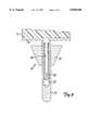
- FIG. 1is a side view, in partial cross-section, of a portion of a hip joint prosthesis in accordance with the invention
- FIG. 2is a cross-sectional, broken away view taken across line 2--2 of FIG. 1;
- FIG. 3is a schematic front view of the tibial portion of a knee joint in accordance with the invention.
- FIG. 4is a side view, in partial cross-section, of a portion of another hip joint prosthesis similar to that of FIG. 1;
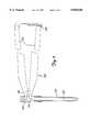
- FIG. 5is an exploded assembly view of parts of instrumentation for use in the assembly of the hip joint prosthesis of FIG. 4;
- FIG. 6is a view of the parts of FIG. 5 as assembled
- FIG. 7is a view of the assembly of FIG. 6 together with a manually operated force generating device.
- FIG. 8is a cross-sectional, broken away view showing another embodiment of the invention.
- a modular hip prosthesisis designated 10, and comprises an elongated stem 12 sized to be received in a surgically prepared intramedullary canal of the femur.
- Axial bore 14is formed in the stem 12.
- a body member 16is provided with a bore 18 sized to closely receive the stem 12, the body having a generally triangular shape when viewed from the side and configured to fit the surgically sculpted proximal end of the intramedullary canal of the femur.
- a neck member 20having a bore 21 sized to closely receive the upper end of the stem 12, the neck including an angled extension 22 terminating in a ball 24 sized to articulate with an appropriately sized and shaped socket prosthesis (not shown) to be mounted in the acetabular recess of the pelvis.
- a clamp 30is shown in FIG. 1 as an elongated metal rod having an axial bore 32 that extends from its proximal end portion 34 to a floor 36 short of the distal end portion 38 of the clamp. Near its upper end, the axial bore 32 has a distally facing shoulder fashioned to receive a placement instrument, as will be described below.
- the clamp 30is shaped and sized such that at body temperature, its diameter, when not constrained in the stem 12, will be slightly larger than the diameter of the bore 14 of the stem.
- the diameter 21 of the neck bore and the diameter 18 of the body boreare essentially the same as the outer diameter of the stem 12; that is, the stem is snugly but slidably received in the bores 18, 21 so that the body and the neck can be moved by hand upon the stem without difficulty.
- a preferred metalis a shape memory alloy such as nitinol, in its superelastic state in which applied stress results in a reversible martensitic phase transition.
- a nitinol claimp 30When a nitinol claimp 30 is stretched as described above, and providing that its temperature is maintained substantially above its ausenite finish temperature (the temperature at which the alloy is completely in its austenitic form), a transition from the austenite phase to the martensite phase occurs. This is known as stress induced martensite formation and is the basis for the phenomenon known as pseudoelasticity or superelasticity.
- the shape memory alloywill remain at least partially in the martensite phase as long as the external stress is maintained.
- the clamp 30Upon release of the stress, however, the clamp 30 will return to the austeniste phase and toward its original shape and size. Because the clamp is constrained within the dimensions of the stem bore 14, however, it will not be able to completely resume its original shape and size. As a result, the clamp 30 will exert a continuous force against the bore 14 of the stem 12.
- the clampmay be made from a shape memory alloy such as nitinol in which the material is capable of undergoing a temperature-induced phase change.
- the shape memory alloyis so configured that when in its stable phase at body temperature, its diameter is slightly greater than the diameter 14 of the stem.
- the clampmay be deformed into a different physical shape in which it is slightly longer and slightly more slender than in its stable form at body temperature, this configuration permitting the clamp to slide into the bore 14 of the stem.
- the shape memory alloyonce the shape memory alloy is warmed and passes through its phase transition temperature range, it expands toward its stable configuration at body temperature, thereby pressing outwardly with a continuous force upon the bore of the stem.
- the clamptends to return to a configuration which may be referred to as a "rest" configuration at body temperature.
- the rest configurationhas a transverse dimension (the diameter in the case of a rod having a circular cross-section) that is slightly larger than the transverse dimension of the stem bore, and as a result the clamp pushes outwardly strongly upon the stem bore and becomes firmly clamped in the stem bore.
- the walls 42 of the clamphave outer surfaces 44 that engage and push outwardly upon the bore 14.
- the outer wall 44 of the clamppushes outwardly upon the surface of the stem bore 14, and the walls of the stem, in turn, are forced outwardly into contact with the inner surface 26 of the body 16 and also with the inner surface 28 of the neck 20.
- the outer surface of the clamp 30is generally cylindrical and makes substantial surface-to-surface contact with the surface of the bore 14.
- the stem wallis sufficiently flexible as to enable the outer wall of the stem to expand into contact with the bores of both the body and the shoulder, even when these bores are slightly different in diameter.
- a feature of a preferred embodiment of the inventionis that the clamped surfaces--that is, the confronting surfaces of the clamp and first member, and the confronting surfaces of the first and second members--mate in surface-to-surface contact to fairly uniformly distribute the compressive forces over the clamped surfaces and preferably to avoid gaps between confronting surfaces.
- a "gap"is the thin void space formed between slightly spaced confronting surfaces of a prosthesis when assembled, as, for example, the space formed between an elongated, smooth-walled rod having threads at one end and the bore receiving the rod.
- the clampis a cylinder having a circular cross-section and the cavity is a circular bore, the compressive clamping force exerted by the clamp against the walls of the bore would be primarily radial and substantially uniform along the length of the clamp.
- Onemay vary as desired the concentration of compressive forces between the clamp (and between prosthesis members) by varying the shapes of the clamping surfaces. For example, if the cross-sections of the clamp and recess were oval rather than circular, one would expect the compressive clamping force to be somewhat greater in the longer transverse dimension than in the shorter transverse dimension.
- FIG. 2The invention in another embodiment is shown in FIG. 2, in which the ball 24 is firmly mounted to the angled neck extension 22.
- the ball 24 and the neck member 20(from which extends the angled extension 22) generally will be assembled as a subunit, and the subunit will then be assembled with the body and stem as mentioned above.
- the angled extension 22has an internal bore 50 that is open at one end and is closed at its other end 52.
- the bore 50extends downwardly and laterally as shown in FIGS. 1 and 2, and opens into the bore 28.
- the distal end of the angled neckhas a tapered head 54 that is received within a tapered bore 60 formed in the ball 24.
- the angled neck 22functions not only as a part of the prosthesis but also as the clamp. To positively and firmly connect the ball 24 to the angled neck, one first elongates the angled neck in the manner described above in connection with the clamp 30.
- the stretching force imparted by the instrumentis withdrawn, and the neck 22 returns toward its original, "rest” configuration, the outer wall of the head 54 bearing outwardly against the confining walls of the bore 60 to firmly clamp the ball to the angled neck.
- the bore 50is fully accessible through its open end prior to mounting of the neck 20 upon the stem 12.
- the clamp and the cavityalthough circular in cross-section and making mutual surface-to-surface contact, are tapered rather than cylindrical, illustrating how the shape of the clamp and cavity may be varied.
- a tibial tray componentis shown generally as 70 and comprises a stem 72 adapted to be received in the surgically prepared intramedullary canal of the tibia in a known fashion.
- the stemterminates upwardly in a metal tray 74 which in turn supports a bearing insert 76 of high molecular weight polyethylene or the like.
- the latteris adapted to articulate with the condyles at the distal end of the femur, or with the condyles of a prosthetic femoral implant, all in a known fashion.
- a shoulder 78which fits in the surgically prepared upper end of the tibial intramedullary canal, and serves to support the upper end of the stem.
- a clamp such as that described aboveis shown at 80 in FIG. 3. It is desirably cylindrical in cross section, having a diameter at body temperature that is slightly greater than the diameter of a bore 82 formed axial within the stem 72.
- the clamp 80may be inserted by the same method described in connection with the clamp 30 of FIG. 1. When the stretching force is withdrawn, the clamp returns toward its "rest" configuration and its walls press outwardly against the walls of the stem 72, causing the latter in turn to clamp strongly to the walls of the bore 84 of the shoulder member 78.
- a slightly modified hip joint prosthesisis depicted in FIG. 4 as 100, the prosthesis having a stem 112 adapted for insertion in the intramedullary canal of the femur.
- An axial bore 114is formed in the stem, and the walls of the stem near its proximal end may have longitudinal slots 116 formed therein, the slots ending in round holes 118 to avoid stress concentration areas.
- the slots 116enable the wall of the stem to expand more easily, and are spaced evenly about the circumference of the stem.
- Four slotsmay be employed.
- a body 120is provided with an internal bore 122 sized to snugly receive the stem, the body bearing a ball 124 similar to ball 24 of FIG. 1.
- the upper or proximal end of the body 120extends slightly beyond the proximal end 126 of the stem.
- Clamp 130Within the stem is received a hollow, tubular clamp 130 similar to the clamp 30 shown in FIG. 1.
- Clamp 130has a proximal, externally threaded end portion 132 that extends beyond the proximal end 126 of the stem but is yet preferably retained in the proximal end portion of the body bore 122, all as shown in FIG. 4.
- FIGS. 5-7depict instrumentation for applying tensile stress to the clamp typified as 130 in the drawing.
- Shown at 140is a tubular gripping tool having an open distal end portion 142 that is internally threaded to receive the external threads of the proximal end portion 132 of the clamp. Square threads preferably are used.
- An aperture 144is formed in the gripping tool 140 proximal of its distal end portion 142.
- An elongated pushing rod 150is received in the hollow clamp, and has a distal end 152 shaped to engage the confronting distal end wall 134 of the clamp in surface-to-surface contact.
- the proximal end 154 of the pushing rodis accessible through the aperture 144, as shown best in FIG. 6, and has a recessed end surface 156.
- the proximal end wall 146 of the tubular gripping toolsimilarly has a recessed surface 148 facing the recessed end surface 156 of the rod.
- FIG. 7depicts the assembly of FIG. 6 in association with a manually operated plier-like force-generating device 170, the device having handles 172, oppositely facing nose portions 174 receivable in the aperture in the gripping tool, and a pivot 176 positioned to provide substantial mechanical advantage to the nose portions.
- Nose portions 174bear against the respective recessed surfaces of the push rod and gripping tool as shown in FIG. 7; squeezing of the handles together results in the application of substantial force to the rod 150, causing the clamp 130 to elongate slightly but sufficiently to enable the clamp to be inserted in the bore of the stem.
- a tooth and pawl mechanism 178 of known design and commonly used with surgical instrumentsis provided at the ends of the handles to hold them together and thus maintain the stem in its stressed, elongated configuration.
- Various other devices capable of delivering substantial force to stretch the clampmay be employed using any of a number of mechanical, pneumatic, and hydraulic means.
- a push rod 150is inserted in an appropriate clamp 130, and the proximal end of the clamp is screwed onto the end of the gripping tool 140 to form the assembly shown in FIG. 6.
- the nose portions 174 of the force-generating device 170are inserted through the aperture 144 into contact with the respective recessed surfaces of the push rod and gripping tool, and the handles are squeezed toward each other and locked by the mechanism 178, thus holding the clamp in its elongated configuration.
- Body 120is received over the stem, and is positioned where desired along the stem by the surgeon during the implantation procedure.
- the clampis inserted into the stem bore.
- Mechanism 178is then released, resulting in the release of pressure of the nose elements against the push rod and gripping tool.
- the clamp 130expands toward its rest configuration, it bears with substantial force against the walls of the stem, forcing these walls into tight contact with the walls of the bore formed in the body.
- the gripping toolis then removed, and the open proximal end of the clamp is capped appropriately if desired.
- the stem of the prosthesis of FIG. 1itself as the clamp, eliminating the clamp 30.
- the proximal end of the stemmay be internally threaded to receive the distal threaded end of an externally threaded gripping tool similar to that shown at 140 in FIG. 6.
- the gripping tool and push rodmay be longer than that shown in the drawing to allow placement of the neck and body over the gripping tool prior to threading the gripping tool onto the threaded end of the stem.
- the gripping tool 140By appropriately configuring the gripping tool 140, one may loosely position the neck 20 and body 16 on the gripping tool prior to use of the device to elongate the proximal portion of the stem.
- the push rod 150is placed in the bore of the stem, and the gripping tool is threaded onto the stem.
- the neck and bodyOnce the stem 12 has been elongated by operation of the force generating device and appropriately positioned in the femoral cavity, the neck and body may be brought down over the nose portions and around the stem and positioned as desired within the intramedullary canal.
- the various parts of the prostheses of the invention that are clamped togetherare made of metal such as stainless steel, cobalt chrome alloys, titanium alloys or the like as are commonly employed for prostheses manufacture.
- the clampsimilarly, may be made of a shape memory alloy or of any metal that exhibits an initial proportional relationship between stress and strain (in the range of validity of Hooke's law).
- Various metals and metal alloyssatisfy this requirement, including stainless steel.
- the ratio of the lateral or transverse strain to the longitudinal or axial straincommonly referred to as Poisson's ratio, can range from 0.2 to 0.5, depending on the material and its condition. Poisson's ratio for stainless steel, for example, is about 0.28.
- the clamps according to the inventionpreferably are made of a shape memory alloy such as nitinol.
- Nitinolexhibits a Poisson's ratio of about 0.3, but this ratio significantly increases up to approximately 0.5 or more when the shape memory alloy is stretched beyond its initial elastic limit; that is, when the formation of stress-induced martensite begins to occur.
- Nitinolis a pseudoelastic material, that is, a material that exhibits superelasticity at room temperature.
- a number of shape memory alloysare known to exhibit the superelastic/pseudoelastic recovery characteristic, and these are generally characterized by their ability, at room or body temperature, to be deformed from an austenitic crystal structure to a stressed-induced martensitic structure, returning to the austenitic state when the stress is removed.
- the alternate crystal structuresgive the alloy superelastic or pseudoelastic properties.
- Nitinol clamps of the type referred to above in connection with FIGS. 1 and 3can readily be elongated up to 8% or more through the use of instruments such as that shown in FIG. 4.
- nitinolwith an assumed Poisson's ratio of 0.3
- a clampsuch as that shown in FIG. 6 is elongated 8%, it would be expected to shrink about 2.4% in diameter.
- the initial diameter of a clampwere in the neighborhood of 1/2 inch, the decrease in diameter would be on the order of 0.012 inches. Since tooling tolerances for the internal bores of stems and other prosthesis parts can easily be held within ⁇ 0.002 inches, a change of 0.012 inches in the clamp diameter allows substantial room for design variations in size. It is generally preferred that the diameter of the stem bore, however, be only very slightly greater than the outer diameter of the clamp when the clamp is longitudinally stretched to an elongation of, for example, 8%.
- a surgeonmay select the desired sizes of the stem, body and head, and can assemble the same during a surgical procedure.
- an articulating ball 124 of the appropriate sizeis selected and is mounted as described above to the neck 120.
- the femoral prosthesis without the clamp 130is then assembled. Assembly may take place away from the patient if the desired dimensions and respective angles of the prosthesis parts are known with accuracy ahead of time, as by measurement or by use of trial prosthesis parts.
- the prosthesis itselfcan be assembled in the intramedullary canal of the patient, with the correct orientations of the parts noted. Referring to FIGS.
- a clamp 130is tensioned to reduce its diameter through use of the gripping tool 140, the pushrod 150 and the force generating device 170, and is then gently placed in the bore of the stem.
- the clampexpands immediately toward its larger diameter "rest” configuration, thereby clamping itself to the stem and clamping the stem 112 to the body 120.
- the resulting prosthesisdesirably has no threaded fastenings to come loose.
- the body 120may be positioned independently in axial and rotational directions on the stem as the surgeon may deem appropriate for the particular patient. In the same manner in which assembly was carried out, disassembly can be afforded by reversing the steps.
- the clamp 80may be inserted in the bore 82 and permitted to expand toward its "rest" configuration. This, in turn, forces the walls of the stem outwardly and to contact with the bore 84 of the shoulder 78 to lock the stem and shoulder together.
- clamp of the inventionhas been described in terms of a hollow rod with one open end and one closed end, it should be understood that a variety of clamp configurations may be employed. If a change of shape of the clamp due to a martensite to austenite shape memory alloy phase change is desired, then a solid rather than hollow clamp may be preferred. Hollow structures are preferred even in this instance, however, in that the hollow interior of the clamp provides a means for cooling the clamp in the event that a prosthesis needs to be disassembled.
- the outer surface of the clamp and the inner surfaces of the bore or bores within which the clamp is receivedbe smooth and regular so as to make good surface-to-surface contact
- the outer surface of the clampmay, in fact, be ridged or roughened or longitudinally fluted or otherwise configured, as desired.
- the clamps of the inventionneed not be round in cross section nor must they have a uniform dimension transverse to the longitudinal axis. If desired, the outer surface of the clamp may have a greater transverse dimension in some areas than in others. For example, with reference to FIG. 1, the transverse dimension of the clamp may be greater near the top of the clamp where the stem portion that is clamped bears also against the bore of the body or vice versa.
- the clampmay in fact be hollow or tubular in design.
- head 54 of the neck extension 22may be formed with a thimble-shaped clamp 180 having an outwardly flared skirt 182 at its open end.
- the rim of the opening 60encounters the skirt 182 and forces the walls of the clamp to elongate.
- the walls of the clampincrease slightly in thickness, wedging the ball onto the head 54 and sealing the opening 60.
- the interface 61 between the head 54 and the clamp 180is also sealed.
- the confronting walls of the clamp and cavitymay be so configured that any slippage between the clamp and the cavity results in the clamp being urged more deeply into the cavity.
- the confronting walls of the clamp or cavity or bothmay be configured to have circumferential shoulders or tapered surfaces or other shapes, that coact to preferentially urge the clamp to move or "walk" in one direction rather than the opposite direction upon repeated slippage between the confronting surfaces.
- the diameters 131, 133 of the clamp 130 and the bore in the stem 112may be slightly greater near the distal end of the stem 112 than near the proximal end so that any movement or "walking" of the clamp due to repeated slippage of the clamp and the stem bore urges the clamp distally within the stem, drawing the widened threaded shoulder at the proximal end of the clamp into contact with the proximal end 126 of the stem.
Landscapes
- Health & Medical Sciences (AREA)
- Orthopedic Medicine & Surgery (AREA)
- Transplantation (AREA)
- Heart & Thoracic Surgery (AREA)
- Life Sciences & Earth Sciences (AREA)
- Oral & Maxillofacial Surgery (AREA)
- Engineering & Computer Science (AREA)
- Biomedical Technology (AREA)
- Veterinary Medicine (AREA)
- Vascular Medicine (AREA)
- Cardiology (AREA)
- Animal Behavior & Ethology (AREA)
- General Health & Medical Sciences (AREA)
- Public Health (AREA)
- Physical Education & Sports Medicine (AREA)
- Prostheses (AREA)
- Mutual Connection Of Rods And Tubes (AREA)
- Insertion Pins And Rivets (AREA)
Abstract
Description
Claims (20)
Priority Applications (17)
| Application Number | Priority Date | Filing Date | Title |
|---|---|---|---|
| US08/567,650US5858020A (en) | 1995-12-05 | 1995-12-05 | Modular prosthesis |
| TW085100277ATW477693B (en) | 1995-12-05 | 1996-01-11 | Kit for making a modular prosthesis |
| CA002239551ACA2239551A1 (en) | 1995-12-05 | 1996-12-05 | Modular prosthesis |
| KR1019980704253AKR19990071963A (en) | 1995-12-05 | 1996-12-05 | Modular prosthetics |
| PCT/US1996/019376WO1997020525A1 (en) | 1995-12-05 | 1996-12-05 | Modular prosthesis |
| AU11474/97AAU730597B2 (en) | 1995-12-05 | 1996-12-05 | Modular prosthesis |
| BR9611809-1ABR9611809A (en) | 1995-12-05 | 1996-12-05 | Modular prosthesis |
| ES96942902TES2181929T3 (en) | 1995-12-05 | 1996-12-05 | EQUIPMENT FOR THE PERFORMANCE OF A MODULAR PROTESIS AND PROCEDURE FOR THE ASSEMBLY OF SUCH MODULAR PROTESIS. |
| DK96942902TDK0869752T3 (en) | 1995-12-05 | 1996-12-05 | Modular prosthetic |
| EP96942902AEP0869752B1 (en) | 1995-12-05 | 1996-12-05 | Modular prosthesis |
| DE69623129TDE69623129T2 (en) | 1995-12-05 | 1996-12-05 | MODULAR PROSTHESIS |
| JP09521426AJP2000515030A (en) | 1995-12-05 | 1996-12-05 | Modular prostheses |
| EA199800421AEA000291B1 (en) | 1995-12-05 | 1996-12-05 | Modular prosthesis |
| KR19997011332AKR20010013336A (en) | 1995-12-05 | 1997-06-04 | Modular prosthesis |
| PCT/US1997/009466WO1998055051A1 (en) | 1995-12-05 | 1997-06-04 | Modular prosthesis |
| EP97928774AEP0991378A1 (en) | 1995-12-05 | 1997-06-04 | Modular prosthesis |
| NO982572ANO982572L (en) | 1995-12-05 | 1998-06-04 | Modular Prosthetic |
Applications Claiming Priority (1)
| Application Number | Priority Date | Filing Date | Title |
|---|---|---|---|
| US08/567,650US5858020A (en) | 1995-12-05 | 1995-12-05 | Modular prosthesis |
Publications (1)
| Publication Number | Publication Date |
|---|---|
| US5858020Atrue US5858020A (en) | 1999-01-12 |
Family
ID=24268058
Family Applications (1)
| Application Number | Title | Priority Date | Filing Date |
|---|---|---|---|
| US08/567,650Expired - LifetimeUS5858020A (en) | 1995-12-05 | 1995-12-05 | Modular prosthesis |
Country Status (14)
| Country | Link |
|---|---|
| US (1) | US5858020A (en) |
| EP (2) | EP0869752B1 (en) |
| JP (1) | JP2000515030A (en) |
| KR (2) | KR19990071963A (en) |
| AU (1) | AU730597B2 (en) |
| BR (1) | BR9611809A (en) |
| CA (1) | CA2239551A1 (en) |
| DE (1) | DE69623129T2 (en) |
| DK (1) | DK0869752T3 (en) |
| EA (1) | EA000291B1 (en) |
| ES (1) | ES2181929T3 (en) |
| NO (1) | NO982572L (en) |
| TW (1) | TW477693B (en) |
| WO (2) | WO1997020525A1 (en) |
Cited By (97)
| Publication number | Priority date | Publication date | Assignee | Title |
|---|---|---|---|---|
| US5976188A (en)* | 1997-10-21 | 1999-11-02 | Johnson & Johnson Professional, Inc. | Modular prosthesis system with hybrid fixation |
| US6139584A (en)* | 1998-12-22 | 2000-10-31 | Depuy Orthopaedics, Inc. | Proximal femoral sleeve for a revision hip prosthesis |
| US6203575B1 (en)* | 1998-01-16 | 2001-03-20 | Sulzer Orthopaedie Ag | Modular system for shaft prostheses |
| WO2000070244A3 (en)* | 1999-05-14 | 2001-05-25 | Patrick White | Stress-induced seal |
| US6257593B1 (en) | 1999-05-14 | 2001-07-10 | Patrick Michel White | Stress induced interposed connector |
| US6306174B1 (en)* | 1998-12-18 | 2001-10-23 | Benoist Girard Sas | Femoral component |
| US20020038148A1 (en)* | 2000-03-13 | 2002-03-28 | Jose Fernandez | Modular hip prosthesis |
| US6428578B2 (en)* | 1998-03-18 | 2002-08-06 | Sct Incorporated | Modular prosthesis and connector therefor |
| US6435519B1 (en) | 1999-05-14 | 2002-08-20 | Patrick Michel White | Stress-induced gasket |
| US20030065397A1 (en)* | 2001-08-27 | 2003-04-03 | Hanssen Arlen D. | Prosthetic implant support structure |
| US20030100896A1 (en)* | 2001-11-27 | 2003-05-29 | Lutz Biedermann | Element with a shank and a holding element connected to it for connecting to a rod |
| US6637995B1 (en) | 2000-02-09 | 2003-10-28 | Patrick Michel White | Super-elastic rivet assembly |
| US20030204268A1 (en)* | 2002-04-25 | 2003-10-30 | Medicinelodge, Inc. | Binary attachment mechanism and method for a modular prosthesis |
| US20030204266A1 (en)* | 2002-04-25 | 2003-10-30 | Medicinelodge, Inc. | Modular prosthesis for replacing bone and method |
| US6706072B2 (en) | 2000-11-08 | 2004-03-16 | Depuy Orthopaedics, Inc. | Modular prosthesis having a stem component with a counterbored cavity defined therein and associated method |
| US6749639B2 (en) | 2001-08-27 | 2004-06-15 | Mayo Foundation For Medical Education And Research | Coated prosthetic implant |
| US20040117024A1 (en)* | 2002-12-13 | 2004-06-17 | Gerbec Daniel E. | Modular implant for joint reconstruction and method of use |
| US20040122437A1 (en)* | 2002-12-20 | 2004-06-24 | Dwyer Kimberly A. | Alignment device for modular implants and method |
| US20040122439A1 (en)* | 2002-12-20 | 2004-06-24 | Dwyer Kimberly A. | Adjustable biomechanical templating & resection instrument and associated method |
| US20040122440A1 (en)* | 2002-12-20 | 2004-06-24 | Daniels David W. | Instrument and associated method of trialing for modular hip stems |
| WO2004030556A3 (en)* | 2002-10-04 | 2004-07-29 | Orthosoft Inc | Computer-assisted hip replacement surgery |
| DE10257774A1 (en)* | 2002-12-10 | 2004-07-29 | Hjs Gelenk System Gmbh | Artificial joint |
| US20040162619A1 (en)* | 2001-08-27 | 2004-08-19 | Zimmer Technology, Inc. | Tibial augments for use with knee joint prostheses, method of implanting the tibial augment, and associated tools |
| US20040254646A1 (en)* | 2003-06-16 | 2004-12-16 | Stone Kevin T. | Provisional coupling mechanism |
| US20040260399A1 (en)* | 2001-09-21 | 2004-12-23 | Poon-Ung Chieng | Device for propecting femoral neck |
| US20040267373A1 (en)* | 2003-06-25 | 2004-12-30 | Dwyer Kimberly Ann | Assembly tool for modular implants and associated method |
| US20040267267A1 (en)* | 2003-06-25 | 2004-12-30 | Daniels David Wayne | Non-linear reamer for bone preparation and associated method |
| US20050004679A1 (en)* | 2003-07-03 | 2005-01-06 | Gary Sederholm | Modular hip prosthesis |
| US6840700B1 (en)* | 1998-07-30 | 2005-01-11 | G. Rau Gmbh & Co. Kg | Mechanical connecting element |
| US6852132B1 (en)* | 2000-07-05 | 2005-02-08 | Russell A Houser | Artificial limbs incorporating superelastic supports |
| US20050033444A1 (en)* | 2003-06-25 | 2005-02-10 | Jones Michael C. | Assembly tool for modular implants and associated method |
| US6863690B2 (en) | 2002-09-27 | 2005-03-08 | Depuy Products, Inc. | Humeral shoulder prosthesis |
| US6866683B2 (en) | 2002-12-13 | 2005-03-15 | Medicine Lodge, Inc. | Modular implant for joint reconstruction and method of use |
| US20050075735A1 (en)* | 2000-04-10 | 2005-04-07 | Berelsman Brian K. | Method and apparatus for adjusting height and angle for a radial head |
| US6902583B2 (en) | 2002-04-25 | 2005-06-07 | Medicinelodge, Inc. | Tripartite attachment mechanism and method for a modular prosthesis |
| US20050125067A1 (en)* | 2003-12-08 | 2005-06-09 | Sweeney Patrick J. | Modular cannulated total joint prosthesis |
| US6913623B1 (en) | 2000-08-15 | 2005-07-05 | Centerpulse Orthopedics, Inc. | Two piecefused femoral hip stem |
| US20050165493A1 (en)* | 2004-01-22 | 2005-07-28 | Ries Michael D. | Femoral hip prosthesis and method of implantation |
| US20050234462A1 (en)* | 2004-01-05 | 2005-10-20 | Hershberger Troy W | Method and instrumentation for performing minimally invasive hip arthroplasty |
| US20060004463A1 (en)* | 2004-06-30 | 2006-01-05 | Lewis Paul P | Extended radius prosthesis and associated method |
| RU2268685C2 (en)* | 2004-02-19 | 2006-01-27 | Государственное научное учреждение "Институт механики металлополимерных систем им. В.А.Белого НАН Беларуси" | Hip joint's endoprosthesis caput |
| US7074224B2 (en) | 2003-06-25 | 2006-07-11 | Depuy Products, Inc. | Modular tapered reamer for bone preparation and associated method |
| US20060232408A1 (en)* | 2005-04-18 | 2006-10-19 | Sdgi Holdings, Inc. | Method and apparatus for implant identification |
| US7150680B2 (en) | 1999-05-14 | 2006-12-19 | Precimed S.A. | Drive shaft coupling |
| US7179261B2 (en) | 2003-12-16 | 2007-02-20 | Depuy Spine, Inc. | Percutaneous access devices and bone anchor assemblies |
| US20070050039A1 (en)* | 2005-08-30 | 2007-03-01 | Dietz Terry L | Orthopaedic implant, stem and associated method |
| US20070100464A1 (en)* | 2005-10-27 | 2007-05-03 | Zimmer Technology, Inc. | Orthopaedic implant sleeve and method |
| US7235106B2 (en) | 2002-12-20 | 2007-06-26 | Depuy Products, Inc. | Modular hip stems and associated method of trialing |
| US20080161811A1 (en)* | 2006-09-29 | 2008-07-03 | Depuy Products, Inc. | Proximal reamer |
| US20080167722A1 (en)* | 2007-01-10 | 2008-07-10 | Biomet Manufacturing Corp. | Knee Joint Prosthesis System and Method for Implantation |
| US20080243264A1 (en)* | 2007-03-26 | 2008-10-02 | Fonte Matthew V | Proximally Self-Locking Long Bone Prosthesis |
| US20080255560A1 (en)* | 2004-05-21 | 2008-10-16 | Myers Surgical Solutions, Llc | Fracture Fixation and Site Stabilization System |
| US7445639B2 (en) | 2001-02-23 | 2008-11-04 | Biomet Manufacturing Corp. | Knee joint prosthesis |
| US7497874B1 (en) | 2001-02-23 | 2009-03-03 | Biomet Manufacturing Corp. | Knee joint prosthesis |
| US20090112216A1 (en)* | 2007-10-30 | 2009-04-30 | Leisinger Steven R | Taper disengagement tool |
| US20090149964A1 (en)* | 2007-10-10 | 2009-06-11 | Biomet Manufacturing Corp. | Knee joint prosthesis system and method for implantation |
| US20090157189A1 (en)* | 2007-12-13 | 2009-06-18 | Biomet Manufacturing Corp. | Modular Articulating Cement Spacer Mold |
| US20090175978A1 (en)* | 2007-12-13 | 2009-07-09 | Biomet Manufacturing Corp. | Modular Articulating Cement Spacer |
| RU2361545C1 (en)* | 2007-11-26 | 2009-07-20 | Сергей Анатольевич Лунёв | Endoprosthesis of coxal articulation |
| US20090299482A1 (en)* | 2007-01-10 | 2009-12-03 | Biomet Manufacturing Corp. | Knee Joint Prosthesis System and Method for Implantation |
| US20090326672A1 (en)* | 2006-11-28 | 2009-12-31 | Depuy Products, Inc. | Modular Proximal Body Trial |
| US20100046315A1 (en)* | 2008-08-22 | 2010-02-25 | Biomet Manufacturing Corp. | Bone cement mixing cartridge and method of use |
| US20100082031A1 (en)* | 2008-09-30 | 2010-04-01 | Sackett Samuel G | Minimally invasive bone miller apparatus |
| US20100198271A1 (en)* | 2009-02-02 | 2010-08-05 | Vincent Leone | Screw Sheath for Minimally Invasive Spinal Surgery and Method Relating Thereto |
| US20100241236A1 (en)* | 2000-04-10 | 2010-09-23 | Biomet Manufacturing Corp. | Modular Radial Head Prosthesis |
| US20100286696A1 (en)* | 2003-12-30 | 2010-11-11 | Depuy Products, Inc. | Minimally Invasive Bone Miller Apparatus |
| US7857858B2 (en) | 2002-04-25 | 2010-12-28 | Zimmer Technology, Inc. | Modular bone implant, tool, and method |
| US20110112651A1 (en)* | 2001-08-27 | 2011-05-12 | Zimmer, Inc. | Femoral augments for use with knee joint prosthesis |
| US8187280B2 (en) | 2007-10-10 | 2012-05-29 | Biomet Manufacturing Corp. | Knee joint prosthesis system and method for implantation |
| US8292932B2 (en) | 2005-07-08 | 2012-10-23 | Biedermann Technologies Gmbh & Co. Kg | Bone anchoring element |
| US8328873B2 (en) | 2007-01-10 | 2012-12-11 | Biomet Manufacturing Corp. | Knee joint prosthesis system and method for implantation |
| USD684693S1 (en) | 2002-08-22 | 2013-06-18 | Zimmer, Inc. | Prosthetic implant support structure |
| US8518050B2 (en) | 2007-10-31 | 2013-08-27 | DePuy Synthes Products, LLC | Modular taper assembly device |
| US8535382B2 (en) | 2000-04-10 | 2013-09-17 | Biomet Manufacturing, Llc | Modular radial head prostheses |
| US8533921B2 (en) | 2010-06-15 | 2013-09-17 | DePuy Synthes Products, LLC | Spiral assembly tool |
| US8696758B2 (en) | 2011-04-06 | 2014-04-15 | DePuy Synthes Products, LLC | Revision hip prosthesis having an implantable distal stem component |
| US8900317B2 (en) | 2011-05-20 | 2014-12-02 | Zimmer, Inc. | Stabilizing prosthesis support structure |
| US8961516B2 (en) | 2005-05-18 | 2015-02-24 | Sonoma Orthopedic Products, Inc. | Straight intramedullary fracture fixation devices and methods |
| US8998919B2 (en) | 2003-06-25 | 2015-04-07 | DePuy Synthes Products, LLC | Assembly tool for modular implants, kit and associated method |
| US9060820B2 (en) | 2005-05-18 | 2015-06-23 | Sonoma Orthopedic Products, Inc. | Segmented intramedullary fracture fixation devices and methods |
| US20150182340A1 (en)* | 2012-08-06 | 2015-07-02 | Universite de Bordeaux | Condylar prosthesis for a temporo-mandibular joint |
| US9095452B2 (en) | 2010-09-01 | 2015-08-04 | DePuy Synthes Products, Inc. | Disassembly tool |
| US20150272740A1 (en)* | 2012-10-31 | 2015-10-01 | Kyocera Medical Corporation | Artificial hip joint |
| US9155574B2 (en) | 2006-05-17 | 2015-10-13 | Sonoma Orthopedic Products, Inc. | Bone fixation device, tools and methods |
| US9259250B2 (en) | 2006-11-22 | 2016-02-16 | Sonoma Orthopedic Products, Inc. | Fracture fixation device, tools and methods |
| US20170204674A1 (en)* | 2016-01-20 | 2017-07-20 | Baker Hughes Incorporated | Method and apparatus for securing bodies using shape memory materials |
| US9770278B2 (en) | 2014-01-17 | 2017-09-26 | Arthrex, Inc. | Dual tip guide wire |
| US9814499B2 (en) | 2014-09-30 | 2017-11-14 | Arthrex, Inc. | Intramedullary fracture fixation devices and methods |
| US20180073303A1 (en)* | 2016-09-12 | 2018-03-15 | Baker Hughes Incorporated | Mechanical Locking Mechanism Using Shape Memory Materials |
| US10280479B2 (en) | 2016-01-20 | 2019-05-07 | Baker Hughes, A Ge Company, Llc | Earth-boring tools and methods for forming earth-boring tools using shape memory materials |
| US10487589B2 (en) | 2016-01-20 | 2019-11-26 | Baker Hughes, A Ge Company, Llc | Earth-boring tools, depth-of-cut limiters, and methods of forming or servicing a wellbore |
| US11141276B2 (en) | 2017-01-20 | 2021-10-12 | Biomet Manufacturing, Llc | Modular augment component |
| US11419642B2 (en) | 2003-12-16 | 2022-08-23 | Medos International Sarl | Percutaneous access devices and bone anchor assemblies |
| US11826267B2 (en) | 2017-04-12 | 2023-11-28 | Depuy Ireland Unlimited Company | Femoral trialling kit and assembly |
| US12127955B2 (en) | 2021-04-29 | 2024-10-29 | Depuy Ireland Unlimited Company | Trial component and method |
| US12208021B2 (en) | 2018-10-04 | 2025-01-28 | Depuy Ireland Unlimited Company | Prosthesis extraction system |
| US20250221822A1 (en)* | 2024-01-04 | 2025-07-10 | Arthrex, Inc. | Hydraulic taper separator for orthopaedic implant systems and methods of disassembly |
Families Citing this family (12)
| Publication number | Priority date | Publication date | Assignee | Title |
|---|---|---|---|---|
| US5858020A (en)* | 1995-12-05 | 1999-01-12 | Metagen, Llc | Modular prosthesis |
| US5906644A (en)* | 1996-08-30 | 1999-05-25 | Powell; Douglas Hunter | Adjustable modular orthopedic implant |
| WO1998008467A1 (en)* | 1996-08-30 | 1998-03-05 | Hunter Innovations, Inc. | Adjustable modular orthopedic implant |
| AU749190B2 (en)* | 1997-06-04 | 2002-06-20 | Orthopaedic Innovations, Inc. | Modular prosthesis |
| DE19833791A1 (en)* | 1998-07-21 | 2000-01-27 | Merete Management Gmbh | Tool for fitting or removing ball in joint prosthesis |
| EP0995412B1 (en)* | 1998-10-23 | 2004-03-31 | Centerpulse Orthopedics Ltd. | Artificial joint cup |
| GB9828084D0 (en)* | 1998-12-18 | 1999-02-17 | Benoist Girard & Cie | Femoral component |
| US6692530B2 (en)* | 2001-10-17 | 2004-02-17 | Hammill Manufacturing Co. | Split sleeve modular joint |
| EP1743587B1 (en)* | 2005-07-08 | 2008-03-26 | BIEDERMANN MOTECH GmbH | Bone anchoring element |
| KR101239218B1 (en)* | 2010-05-13 | 2013-03-05 | 서울대학교산학협력단 | Bistable intelligence morphing active plate |
| FR2977139B1 (en)* | 2011-06-30 | 2014-08-22 | Ldr Medical | INTER-SPINAL IMPLANT AND IMPLANTATION INSTRUMENT |
| DE102015121779B4 (en)* | 2015-12-15 | 2018-03-29 | Gottfried Wilhelm Leibniz Universität Hannover | Revisionable endoprosthesis |
Citations (31)
| Publication number | Priority date | Publication date | Assignee | Title |
|---|---|---|---|---|
| US3981307A (en)* | 1974-07-01 | 1976-09-21 | Ethicon, Inc. | Thermal attachment of surgical sutures to needles |
| GB1548964A (en)* | 1975-04-09 | 1979-07-18 | Raychem Corp | Fastening devices |
| US4170990A (en)* | 1977-01-28 | 1979-10-16 | Fried. Krupp Gesellschaft Mit Beschrankter Haftung | Method for implanting and subsequently removing mechanical connecting elements from living tissue |
| US4170794A (en)* | 1977-03-23 | 1979-10-16 | Rosenthal Technik Ag | Bone joint endoprosthesis |
| SU1110447A1 (en)* | 1982-09-24 | 1984-08-30 | Новокузнецкий институт усовершенствования врачей | Compressing fixative |
| US4520511A (en)* | 1981-10-26 | 1985-06-04 | Paribelli Gianezio | Hip prosthesis with expanding femoral component |
| US4693724A (en)* | 1985-01-31 | 1987-09-15 | Rhenter Jean L | Total hip prosthesis with primary fixation |
| SU1351591A1 (en)* | 1986-06-17 | 1987-11-15 | Запорожский Областной Отдел Здравоохранения | Intraosseous fixative |
| US4756711A (en)* | 1985-12-24 | 1988-07-12 | Christian Mai | Self-locking prosthesis, and methods for producing and for fitting in same |
| EP0311208A1 (en)* | 1987-10-05 | 1989-04-12 | Ordev B.V. | Adjustable prosthesis |
| US4896955A (en)* | 1983-12-06 | 1990-01-30 | Cvi/Beta Ventures, Inc. | Eyeglass frame including shape-memory elements |
| DE3838388A1 (en)* | 1988-11-11 | 1990-05-17 | Thomas Dr Med Pfeifer | Fastening device |
| US4938773A (en)* | 1989-01-18 | 1990-07-03 | Strand John A | Hip joint prosthesis |
| US4995883A (en)* | 1989-02-08 | 1991-02-26 | Smith & Nephew Richards Inc. | Modular hip prosthesis |
| FR2651119A1 (en)* | 1989-08-23 | 1991-03-01 | Felman Daniel | Phalangeal articular prosthesis |
| US5002578A (en)* | 1990-05-04 | 1991-03-26 | Venus Corporation | Modular hip stem prosthesis apparatus and method |
| US5013507A (en)* | 1989-09-29 | 1991-05-07 | The Boeing Company | Method for producing an elongate passage within a component |
| JPH03159645A (en)* | 1989-11-20 | 1991-07-09 | Ngk Spark Plug Co Ltd | Artificial condyle |
| US5035712A (en)* | 1989-06-16 | 1991-07-30 | Ordev B.V. | Self-adjusting prosthesis attachment |
| US5080685A (en)* | 1986-08-15 | 1992-01-14 | Boehringer Mannheim Corporation | Modular hip prosthesis |
| US5120175A (en)* | 1991-07-15 | 1992-06-09 | Arbegast William J | Shape memory alloy fastener |
| WO1992014423A1 (en)* | 1991-02-22 | 1992-09-03 | Pisharodi Madhavan | Middle expandable intervertebral disk implant and method |
| US5190546A (en)* | 1983-10-14 | 1993-03-02 | Raychem Corporation | Medical devices incorporating SIM alloy elements |
| EP0610575A2 (en)* | 1993-02-11 | 1994-08-17 | Giuseppe Vrespa | Removable stump pin for endosteal implants |
| EP0634154A1 (en)* | 1993-07-16 | 1995-01-18 | MEC HINT S.r.l. | Improvement in the locking among the components of a multicomponent prosthesis for use in traumatology, orthopedics and veterinary medicine |
| US5397360A (en)* | 1993-02-11 | 1995-03-14 | Osteonics Corp. | Modular components for prosthetic implants |
| US5415660A (en)* | 1994-01-07 | 1995-05-16 | Regents Of The University Of Minnesota | Implantable limb lengthening nail driven by a shape memory alloy |
| WO1995013757A1 (en)* | 1993-11-18 | 1995-05-26 | Kirschner Medical Corporation | Modular prosthesis with shape memory alloy elements |
| FR2722679A1 (en)* | 1994-07-25 | 1996-01-26 | Daniel Felman | Expansible arthrodesis implant for insertion between vertebrae |
| US5507826A (en)* | 1993-03-05 | 1996-04-16 | Memory Medical Systems, Inc. | Prosthesis with shape memory locking element |
| US5584695A (en)* | 1994-03-07 | 1996-12-17 | Memory Medical Systems, Inc. | Bone anchoring apparatus and method |
Family Cites Families (1)
| Publication number | Priority date | Publication date | Assignee | Title |
|---|---|---|---|---|
| US5858020A (en)* | 1995-12-05 | 1999-01-12 | Metagen, Llc | Modular prosthesis |
- 1995
- 1995-12-05USUS08/567,650patent/US5858020A/ennot_activeExpired - Lifetime
- 1996
- 1996-01-11TWTW085100277Apatent/TW477693B/ennot_activeIP Right Cessation
- 1996-12-05EAEA199800421Apatent/EA000291B1/ennot_activeIP Right Cessation
- 1996-12-05JPJP09521426Apatent/JP2000515030A/ennot_activeCeased
- 1996-12-05KRKR1019980704253Apatent/KR19990071963A/ennot_activeCeased
- 1996-12-05DEDE69623129Tpatent/DE69623129T2/ennot_activeExpired - Fee Related
- 1996-12-05DKDK96942902Tpatent/DK0869752T3/enactive
- 1996-12-05EPEP96942902Apatent/EP0869752B1/ennot_activeExpired - Lifetime
- 1996-12-05BRBR9611809-1Apatent/BR9611809A/ennot_activeIP Right Cessation
- 1996-12-05ESES96942902Tpatent/ES2181929T3/ennot_activeExpired - Lifetime
- 1996-12-05AUAU11474/97Apatent/AU730597B2/ennot_activeCeased
- 1996-12-05CACA002239551Apatent/CA2239551A1/ennot_activeAbandoned
- 1996-12-05WOPCT/US1996/019376patent/WO1997020525A1/ennot_activeApplication Discontinuation
- 1997
- 1997-06-04EPEP97928774Apatent/EP0991378A1/ennot_activeWithdrawn
- 1997-06-04WOPCT/US1997/009466patent/WO1998055051A1/ennot_activeApplication Discontinuation
- 1997-06-04KRKR19997011332Apatent/KR20010013336A/ennot_activeCeased
- 1998
- 1998-06-04NONO982572Apatent/NO982572L/ennot_activeApplication Discontinuation
Patent Citations (33)
| Publication number | Priority date | Publication date | Assignee | Title |
|---|---|---|---|---|
| US3981307A (en)* | 1974-07-01 | 1976-09-21 | Ethicon, Inc. | Thermal attachment of surgical sutures to needles |
| GB1548964A (en)* | 1975-04-09 | 1979-07-18 | Raychem Corp | Fastening devices |
| US4170990A (en)* | 1977-01-28 | 1979-10-16 | Fried. Krupp Gesellschaft Mit Beschrankter Haftung | Method for implanting and subsequently removing mechanical connecting elements from living tissue |
| US4170794A (en)* | 1977-03-23 | 1979-10-16 | Rosenthal Technik Ag | Bone joint endoprosthesis |
| US4520511A (en)* | 1981-10-26 | 1985-06-04 | Paribelli Gianezio | Hip prosthesis with expanding femoral component |
| SU1110447A1 (en)* | 1982-09-24 | 1984-08-30 | Новокузнецкий институт усовершенствования врачей | Compressing fixative |
| US5190546A (en)* | 1983-10-14 | 1993-03-02 | Raychem Corporation | Medical devices incorporating SIM alloy elements |
| US4896955A (en)* | 1983-12-06 | 1990-01-30 | Cvi/Beta Ventures, Inc. | Eyeglass frame including shape-memory elements |
| US4896955B1 (en)* | 1983-12-06 | 1991-05-21 | Eyeglass frame including shape-memory elements | |
| US4693724A (en)* | 1985-01-31 | 1987-09-15 | Rhenter Jean L | Total hip prosthesis with primary fixation |
| US4756711A (en)* | 1985-12-24 | 1988-07-12 | Christian Mai | Self-locking prosthesis, and methods for producing and for fitting in same |
| SU1351591A1 (en)* | 1986-06-17 | 1987-11-15 | Запорожский Областной Отдел Здравоохранения | Intraosseous fixative |
| US5080685A (en)* | 1986-08-15 | 1992-01-14 | Boehringer Mannheim Corporation | Modular hip prosthesis |
| US4921499A (en)* | 1987-10-05 | 1990-05-01 | Ordev B.V. | Adjustable prosthesis |
| EP0311208A1 (en)* | 1987-10-05 | 1989-04-12 | Ordev B.V. | Adjustable prosthesis |
| DE3838388A1 (en)* | 1988-11-11 | 1990-05-17 | Thomas Dr Med Pfeifer | Fastening device |
| US4938773A (en)* | 1989-01-18 | 1990-07-03 | Strand John A | Hip joint prosthesis |
| US4995883A (en)* | 1989-02-08 | 1991-02-26 | Smith & Nephew Richards Inc. | Modular hip prosthesis |
| US5035712A (en)* | 1989-06-16 | 1991-07-30 | Ordev B.V. | Self-adjusting prosthesis attachment |
| FR2651119A1 (en)* | 1989-08-23 | 1991-03-01 | Felman Daniel | Phalangeal articular prosthesis |
| US5013507A (en)* | 1989-09-29 | 1991-05-07 | The Boeing Company | Method for producing an elongate passage within a component |
| JPH03159645A (en)* | 1989-11-20 | 1991-07-09 | Ngk Spark Plug Co Ltd | Artificial condyle |
| US5002578A (en)* | 1990-05-04 | 1991-03-26 | Venus Corporation | Modular hip stem prosthesis apparatus and method |
| WO1992014423A1 (en)* | 1991-02-22 | 1992-09-03 | Pisharodi Madhavan | Middle expandable intervertebral disk implant and method |
| US5120175A (en)* | 1991-07-15 | 1992-06-09 | Arbegast William J | Shape memory alloy fastener |
| EP0610575A2 (en)* | 1993-02-11 | 1994-08-17 | Giuseppe Vrespa | Removable stump pin for endosteal implants |
| US5397360A (en)* | 1993-02-11 | 1995-03-14 | Osteonics Corp. | Modular components for prosthetic implants |
| US5507826A (en)* | 1993-03-05 | 1996-04-16 | Memory Medical Systems, Inc. | Prosthesis with shape memory locking element |
| EP0634154A1 (en)* | 1993-07-16 | 1995-01-18 | MEC HINT S.r.l. | Improvement in the locking among the components of a multicomponent prosthesis for use in traumatology, orthopedics and veterinary medicine |
| WO1995013757A1 (en)* | 1993-11-18 | 1995-05-26 | Kirschner Medical Corporation | Modular prosthesis with shape memory alloy elements |
| US5415660A (en)* | 1994-01-07 | 1995-05-16 | Regents Of The University Of Minnesota | Implantable limb lengthening nail driven by a shape memory alloy |
| US5584695A (en)* | 1994-03-07 | 1996-12-17 | Memory Medical Systems, Inc. | Bone anchoring apparatus and method |
| FR2722679A1 (en)* | 1994-07-25 | 1996-01-26 | Daniel Felman | Expansible arthrodesis implant for insertion between vertebrae |
Cited By (246)
| Publication number | Priority date | Publication date | Assignee | Title |
|---|---|---|---|---|
| US5976188A (en)* | 1997-10-21 | 1999-11-02 | Johnson & Johnson Professional, Inc. | Modular prosthesis system with hybrid fixation |
| US6203575B1 (en)* | 1998-01-16 | 2001-03-20 | Sulzer Orthopaedie Ag | Modular system for shaft prostheses |
| US6699293B2 (en)* | 1998-03-18 | 2004-03-02 | Sct Incorporated | Prosthesis having wedge-shaped body |
| US6428578B2 (en)* | 1998-03-18 | 2002-08-06 | Sct Incorporated | Modular prosthesis and connector therefor |
| US6840700B1 (en)* | 1998-07-30 | 2005-01-11 | G. Rau Gmbh & Co. Kg | Mechanical connecting element |
| US6306174B1 (en)* | 1998-12-18 | 2001-10-23 | Benoist Girard Sas | Femoral component |
| US6139584A (en)* | 1998-12-22 | 2000-10-31 | Depuy Orthopaedics, Inc. | Proximal femoral sleeve for a revision hip prosthesis |
| US6435519B1 (en) | 1999-05-14 | 2002-08-20 | Patrick Michel White | Stress-induced gasket |
| WO2000070244A3 (en)* | 1999-05-14 | 2001-05-25 | Patrick White | Stress-induced seal |
| US6257593B1 (en) | 1999-05-14 | 2001-07-10 | Patrick Michel White | Stress induced interposed connector |
| US7150680B2 (en) | 1999-05-14 | 2006-12-19 | Precimed S.A. | Drive shaft coupling |
| US6513814B2 (en)* | 1999-05-14 | 2003-02-04 | Patrick Michel White | Stress induced connecting assembly |
| US6637995B1 (en) | 2000-02-09 | 2003-10-28 | Patrick Michel White | Super-elastic rivet assembly |
| WO2001069108A1 (en)* | 2000-03-11 | 2001-09-20 | Patrick White | Stress-induced interposed connector |
| US20020038148A1 (en)* | 2000-03-13 | 2002-03-28 | Jose Fernandez | Modular hip prosthesis |
| US6911048B2 (en)* | 2000-03-13 | 2005-06-28 | Exactech, Inc. | Modular hip prosthesis |
| US8920509B2 (en) | 2000-04-10 | 2014-12-30 | Biomet Manufacturing, Llc | Modular radial head prosthesis |
| US20100312349A1 (en)* | 2000-04-10 | 2010-12-09 | Biomet Manufacturing Corp. | Modular prosthesis and use thereof for replacing a radial head |
| US8535382B2 (en) | 2000-04-10 | 2013-09-17 | Biomet Manufacturing, Llc | Modular radial head prostheses |
| US9579208B2 (en) | 2000-04-10 | 2017-02-28 | Biomet Manufacturing, Llc | Modular radial head prosthesis |
| US8425615B2 (en) | 2000-04-10 | 2013-04-23 | Biomet Manufacturing Corp. | Method and apparatus for adjusting height and angle for a radial head |
| US20100241236A1 (en)* | 2000-04-10 | 2010-09-23 | Biomet Manufacturing Corp. | Modular Radial Head Prosthesis |
| US8366781B2 (en) | 2000-04-10 | 2013-02-05 | Biomet Manufacturing Corp. | Modular prosthesis and use thereof for replacing a radial head |
| US20100262252A1 (en)* | 2000-04-10 | 2010-10-14 | Biomet Manufacturing Corp. | Modular prosthesis and use thereof for replacing a radial head |
| US20110125276A1 (en)* | 2000-04-10 | 2011-05-26 | Biomet Manufacturing Corp. | Modular prosthesis and use thereof for replacing a radial head |
| US20100030339A1 (en)* | 2000-04-10 | 2010-02-04 | Biomet Manufacturing Corp. | Method and apparatus for adjusting height and angle for a radial head |
| US20050075735A1 (en)* | 2000-04-10 | 2005-04-07 | Berelsman Brian K. | Method and apparatus for adjusting height and angle for a radial head |
| US8114163B2 (en) | 2000-04-10 | 2012-02-14 | Biomet Manufacturing Corp. | Method and apparatus for adjusting height and angle for a radial head |
| US8110005B2 (en) | 2000-04-10 | 2012-02-07 | Biomet Manufacturing Corp. | Modular prosthesis and use thereof for replacing a radial head |
| US9439784B2 (en) | 2000-04-10 | 2016-09-13 | Biomet Manufacturing, Llc | Modular radial head prosthesis |
| US20110144759A1 (en)* | 2000-04-10 | 2011-06-16 | Biomet Manufacturing Corp. | Modular prosthesis and use thereof for replacing a radial head |
| US9333084B2 (en) | 2000-04-10 | 2016-05-10 | Biomet Manufacturing, Llc | Modular prosthesis and use thereof for replacing a radial head |
| US6852132B1 (en)* | 2000-07-05 | 2005-02-08 | Russell A Houser | Artificial limbs incorporating superelastic supports |
| US6913623B1 (en) | 2000-08-15 | 2005-07-05 | Centerpulse Orthopedics, Inc. | Two piecefused femoral hip stem |
| US6706072B2 (en) | 2000-11-08 | 2004-03-16 | Depuy Orthopaedics, Inc. | Modular prosthesis having a stem component with a counterbored cavity defined therein and associated method |
| US6723129B2 (en) | 2000-11-08 | 2004-04-20 | Depuy Orthopaedics, Inc. | Self-locking modular prosthesis having taper feature and associated method |
| US7122056B2 (en) | 2000-11-08 | 2006-10-17 | Depuy Orthopaedics, Inc. | Self-locking modular prosthesis |
| US7445639B2 (en) | 2001-02-23 | 2008-11-04 | Biomet Manufacturing Corp. | Knee joint prosthesis |
| US7497874B1 (en) | 2001-02-23 | 2009-03-03 | Biomet Manufacturing Corp. | Knee joint prosthesis |
| US10646346B2 (en) | 2001-08-27 | 2020-05-12 | Zimmer, Inc. | Prosthetic implant support structure |
| US10092404B2 (en) | 2001-08-27 | 2018-10-09 | Zimmer, Inc. | Prosthetic implant support structure |
| US9044326B2 (en) | 2001-08-27 | 2015-06-02 | Zimmer, Inc. | Femoral augments for use with knee joint prosthesis |
| US10806587B2 (en) | 2001-08-27 | 2020-10-20 | Zimmer, Inc. | Prosthetic implant support structure |
| US8728168B2 (en) | 2001-08-27 | 2014-05-20 | Zimmer, Inc. | Prosthetic implant support structure |
| US9539096B2 (en) | 2001-08-27 | 2017-01-10 | Zimmer, Inc. | Methods for supporting a prosthetic implant in a patient |
| US6749639B2 (en) | 2001-08-27 | 2004-06-15 | Mayo Foundation For Medical Education And Research | Coated prosthetic implant |
| US8535385B2 (en) | 2001-08-27 | 2013-09-17 | Zimmer, Inc. | Prosthetic implant support structure |
| US20100145452A1 (en)* | 2001-08-27 | 2010-06-10 | Zimmer, Inc. | Prosthetic implant support structure |
| US10893947B2 (en) | 2001-08-27 | 2021-01-19 | Zimmer, Inc. | Femoral augments for use with knee joint prosthesis |
| US9713532B2 (en) | 2001-08-27 | 2017-07-25 | Zimmer, Inc. | Method for augmenting femoral components of knee joint prosthesis |
| US8506645B2 (en) | 2001-08-27 | 2013-08-13 | Zimmer, Inc. | Tibial augments for use with knee joint prostheses |
| US10653526B2 (en) | 2001-08-27 | 2020-05-19 | Zimmer, Inc. | Prosthetic implant support structure |
| US9907664B2 (en) | 2001-08-27 | 2018-03-06 | Zimmer, Inc. | Methods for augmenting a tibial component of a knee joint prosthesis |
| US10085841B2 (en) | 2001-08-27 | 2018-10-02 | Zimmer, Inc. | Femoral implant systems |
| US20040162619A1 (en)* | 2001-08-27 | 2004-08-19 | Zimmer Technology, Inc. | Tibial augments for use with knee joint prostheses, method of implanting the tibial augment, and associated tools |
| US20110009974A1 (en)* | 2001-08-27 | 2011-01-13 | Zimmer Technology, Inc. | Tibial augments for use with knee joint prostheses, method of implanting the tibial augment, and associated tools |
| US10098743B2 (en) | 2001-08-27 | 2018-10-16 | Zimmer, Inc. | Prosthetic implant support structure |
| US10201426B2 (en) | 2001-08-27 | 2019-02-12 | Zimmer, Inc. | Prosthetic implant support structure |
| US20070088443A1 (en)* | 2001-08-27 | 2007-04-19 | Hanssen Arlen D | Prosthetic implant support structure |
| US9265614B2 (en) | 2001-08-27 | 2016-02-23 | Zimmer, Inc. | Method of implanting the tibial augment |
| US20030065397A1 (en)* | 2001-08-27 | 2003-04-03 | Hanssen Arlen D. | Prosthetic implant support structure |
| US20110112651A1 (en)* | 2001-08-27 | 2011-05-12 | Zimmer, Inc. | Femoral augments for use with knee joint prosthesis |
| US7458990B2 (en)* | 2001-09-21 | 2008-12-02 | Poon-Ung Chieng | Device for protecting femoral neck |
| US20040260399A1 (en)* | 2001-09-21 | 2004-12-23 | Poon-Ung Chieng | Device for propecting femoral neck |
| US20030100896A1 (en)* | 2001-11-27 | 2003-05-29 | Lutz Biedermann | Element with a shank and a holding element connected to it for connecting to a rod |
| US9895173B2 (en) | 2001-11-27 | 2018-02-20 | Biedermann Technologies Gmbh & Co. Kg | Element with a shank and a holding element connected to it for connecting to a rod |
| US10792075B2 (en) | 2001-11-27 | 2020-10-06 | Biedermann Technologies Gmbh & Co. Kg | Element with a shank and a holding element connected to it for connecting to a rod |
| US8828060B2 (en)* | 2001-11-27 | 2014-09-09 | Biedermann Technologies Gmbh & Co. Kg | Element with a shank and a holding element connected to it for connecting to a rod |
| US7857858B2 (en) | 2002-04-25 | 2010-12-28 | Zimmer Technology, Inc. | Modular bone implant, tool, and method |
| US6902583B2 (en) | 2002-04-25 | 2005-06-07 | Medicinelodge, Inc. | Tripartite attachment mechanism and method for a modular prosthesis |
| US6875239B2 (en)* | 2002-04-25 | 2005-04-05 | Medicinelodge, Inc. | Modular prosthesis for replacing bone and method |
| US20110066249A1 (en)* | 2002-04-25 | 2011-03-17 | Zimmer Technology, Inc. | Modular bone implant, tool, and method |
| US20030204268A1 (en)* | 2002-04-25 | 2003-10-30 | Medicinelodge, Inc. | Binary attachment mechanism and method for a modular prosthesis |
| US20030204266A1 (en)* | 2002-04-25 | 2003-10-30 | Medicinelodge, Inc. | Modular prosthesis for replacing bone and method |
| US8241367B2 (en) | 2002-04-25 | 2012-08-14 | Zimmer, Inc. | Modular bone implant, tool, and method |
| USD684693S1 (en) | 2002-08-22 | 2013-06-18 | Zimmer, Inc. | Prosthetic implant support structure |
| US6863690B2 (en) | 2002-09-27 | 2005-03-08 | Depuy Products, Inc. | Humeral shoulder prosthesis |
| US11311339B2 (en) | 2002-10-04 | 2022-04-26 | Orthosoft Inc. | Computer-assisted hip replacement surgery |
| US10219865B2 (en) | 2002-10-04 | 2019-03-05 | Orthosoft Inc. | Computer-assisted hip replacement surgery |
| EP1870053A3 (en)* | 2002-10-04 | 2008-05-21 | Orthosoft Inc. | Computer-assisted hip replacement surgery |
| US20050021043A1 (en)* | 2002-10-04 | 2005-01-27 | Herbert Andre Jansen | Apparatus for digitizing intramedullary canal and method |
| US9339277B2 (en) | 2002-10-04 | 2016-05-17 | Orthosoft Holdings Inc. | Computer-assisted hip replacement surgery |
| US20040230199A1 (en)* | 2002-10-04 | 2004-11-18 | Jansen Herbert Andre | Computer-assisted hip replacement surgery |
| WO2004030556A3 (en)* | 2002-10-04 | 2004-07-29 | Orthosoft Inc | Computer-assisted hip replacement surgery |
| US20060206210A1 (en)* | 2002-12-10 | 2006-09-14 | Hjs Gelenk System Gmbh | Artificial joint |
| DE10257774A1 (en)* | 2002-12-10 | 2004-07-29 | Hjs Gelenk System Gmbh | Artificial joint |
| US6887276B2 (en) | 2002-12-13 | 2005-05-03 | Medicine Lodge, Inc | Modular implant for joint reconstruction and method of use |
| US6866683B2 (en) | 2002-12-13 | 2005-03-15 | Medicine Lodge, Inc. | Modular implant for joint reconstruction and method of use |
| US20040117024A1 (en)* | 2002-12-13 | 2004-06-17 | Gerbec Daniel E. | Modular implant for joint reconstruction and method of use |
| US8529578B2 (en) | 2002-12-20 | 2013-09-10 | DePuy Synthes Products, LLC | Instrument and associated method of trialing for modular hip stems |
| US20040122439A1 (en)* | 2002-12-20 | 2004-06-24 | Dwyer Kimberly A. | Adjustable biomechanical templating & resection instrument and associated method |
| US20070244566A1 (en)* | 2002-12-20 | 2007-10-18 | Depuy Products, Inc. | Trialing system and method for modular hip joint replacement system |
| US7022141B2 (en) | 2002-12-20 | 2006-04-04 | Depuy Products, Inc. | Alignment device for modular implants and method |
| US7235106B2 (en) | 2002-12-20 | 2007-06-26 | Depuy Products, Inc. | Modular hip stems and associated method of trialing |
| US20110046745A1 (en)* | 2002-12-20 | 2011-02-24 | Depuy Products, Inc. | Instrument and associated method of trialing for modular hip stems |
| US20040122437A1 (en)* | 2002-12-20 | 2004-06-24 | Dwyer Kimberly A. | Alignment device for modular implants and method |
| US7854737B2 (en) | 2002-12-20 | 2010-12-21 | Depuy Products, Inc. | Instrument and associated method of trailing for modular hip stems |
| US20100292806A1 (en)* | 2002-12-20 | 2010-11-18 | Depuy Products, Inc. | Trialing System and Method for Modular Hip Joint Replacement System |
| US20040122440A1 (en)* | 2002-12-20 | 2004-06-24 | Daniels David W. | Instrument and associated method of trialing for modular hip stems |
| US7794503B2 (en) | 2002-12-20 | 2010-09-14 | Depuy Products, Inc. | Trialing system and method for modular hip joint replacement system |
| US20040254646A1 (en)* | 2003-06-16 | 2004-12-16 | Stone Kevin T. | Provisional coupling mechanism |
| US7582092B2 (en) | 2003-06-25 | 2009-09-01 | Depuy Products, Inc. | Assembly tool for modular implants and associated method |
| US20070162033A1 (en)* | 2003-06-25 | 2007-07-12 | Daniels David W | Modular tapered reamer for bone preparation and associated method |
| US8790346B2 (en) | 2003-06-25 | 2014-07-29 | DePuy Synthes Products, LLC | Modular tapered reamer for bone preparation and associated method |
| US8419799B2 (en) | 2003-06-25 | 2013-04-16 | Depuy Products, Inc. | Assembly tool for modular implants and associated method |
| US9381097B2 (en) | 2003-06-25 | 2016-07-05 | DePuy Synthes Products, Inc. | Assembly tool for modular implants, kit and associated method |
| US20110125154A1 (en)* | 2003-06-25 | 2011-05-26 | Depuy Products, Inc. | Non-linear reamer for bone preparation and associated method |
| US20040267267A1 (en)* | 2003-06-25 | 2004-12-30 | Daniels David Wayne | Non-linear reamer for bone preparation and associated method |
| US7074224B2 (en) | 2003-06-25 | 2006-07-11 | Depuy Products, Inc. | Modular tapered reamer for bone preparation and associated method |
| US8998919B2 (en) | 2003-06-25 | 2015-04-07 | DePuy Synthes Products, LLC | Assembly tool for modular implants, kit and associated method |
| US8685036B2 (en) | 2003-06-25 | 2014-04-01 | Michael C. Jones | Assembly tool for modular implants and associated method |
| US7297166B2 (en) | 2003-06-25 | 2007-11-20 | Depuy Products, Inc. | Assembly tool for modular implants and associated method |
| US20050033444A1 (en)* | 2003-06-25 | 2005-02-10 | Jones Michael C. | Assembly tool for modular implants and associated method |
| US20080091212A1 (en)* | 2003-06-25 | 2008-04-17 | Depuy Products, Inc. | Assembly tool for modular implants and associated method |
| US20040267373A1 (en)* | 2003-06-25 | 2004-12-30 | Dwyer Kimberly Ann | Assembly tool for modular implants and associated method |
| EP1493407A3 (en)* | 2003-07-03 | 2005-04-13 | Centerpulse Orthopedics Inc. | Modular hip prosthesis |
| AU2004203031B2 (en)* | 2003-07-03 | 2009-07-23 | Zimmer, Inc. | Modular hip prosthesis |
| US7468078B2 (en) | 2003-07-03 | 2008-12-23 | Zimmer, Inc. | Modular hip prosthesis |
| US20050004679A1 (en)* | 2003-07-03 | 2005-01-06 | Gary Sederholm | Modular hip prosthesis |
| US20050125067A1 (en)* | 2003-12-08 | 2005-06-09 | Sweeney Patrick J. | Modular cannulated total joint prosthesis |
| US7766968B2 (en)* | 2003-12-08 | 2010-08-03 | Sweeney Patrick J | Modular cannulated total joint prosthesis |
| US8617210B2 (en) | 2003-12-16 | 2013-12-31 | Depuy Spine, Sarl | Percutaneous access devices and bone anchor assemblies |
| US11419642B2 (en) | 2003-12-16 | 2022-08-23 | Medos International Sarl | Percutaneous access devices and bone anchor assemblies |
| US7179261B2 (en) | 2003-12-16 | 2007-02-20 | Depuy Spine, Inc. | Percutaneous access devices and bone anchor assemblies |
| US10299839B2 (en) | 2003-12-16 | 2019-05-28 | Medos International Sárl | Percutaneous access devices and bone anchor assemblies |
| US8518082B2 (en) | 2003-12-16 | 2013-08-27 | Depuy Spine, Sarl | Percutaneous access devices and bone anchor assemblies |
| US7854751B2 (en) | 2003-12-16 | 2010-12-21 | Dupuy Spine, Inc. | Percutaneous access devices and bone anchor assemblies |
| US20100286696A1 (en)* | 2003-12-30 | 2010-11-11 | Depuy Products, Inc. | Minimally Invasive Bone Miller Apparatus |
| US7942879B2 (en) | 2003-12-30 | 2011-05-17 | Depuy Products, Inc. | Minimally invasive bone miller apparatus |
| US20050234463A1 (en)* | 2004-01-05 | 2005-10-20 | Hershberger Troy W | Method and instrumentation for performing minimally invasive hip arthroplasty |
| US20050234462A1 (en)* | 2004-01-05 | 2005-10-20 | Hershberger Troy W | Method and instrumentation for performing minimally invasive hip arthroplasty |
| US7976545B2 (en) | 2004-01-05 | 2011-07-12 | Biomet Manufacturing Corp. | Method and instrumentation for performing minimally invasive hip arthroplasty |
| US7854769B2 (en) | 2004-01-05 | 2010-12-21 | Biomet Manufacturing Corp. | Method and instrumentation for performing minimally invasive hip arthroplasty |
| US7833228B1 (en) | 2004-01-05 | 2010-11-16 | Biomet Manufacturing Corp. | Method and instrumentation for performing minimally invasive hip arthroplasty |
| US8157871B2 (en) | 2004-01-22 | 2012-04-17 | Michael D Ries | Femoral HIP prosthesis and method of implantation |
| US20050165493A1 (en)* | 2004-01-22 | 2005-07-28 | Ries Michael D. | Femoral hip prosthesis and method of implantation |
| US20110004319A1 (en)* | 2004-01-22 | 2011-01-06 | Michael D. Ries | Femoral Hip Prosthesis and Method of Implantation |
| US7534271B2 (en) | 2004-01-22 | 2009-05-19 | Smith + Nephew | Femoral hip prosthesis and method of implantation |
| US7374576B1 (en) | 2004-01-22 | 2008-05-20 | Medicinelodge, Inc | Polyaxial orthopedic fastening apparatus with independent locking modes |
| US20090216335A1 (en)* | 2004-01-22 | 2009-08-27 | Smith & Nephew | Femoral Hip Prosthesis and Method of Implantation |
| RU2268685C2 (en)* | 2004-02-19 | 2006-01-27 | Государственное научное учреждение "Институт механики металлополимерных систем им. В.А.Белого НАН Беларуси" | Hip joint's endoprosthesis caput |
| US20080255560A1 (en)* | 2004-05-21 | 2008-10-16 | Myers Surgical Solutions, Llc | Fracture Fixation and Site Stabilization System |
| US8163029B2 (en) | 2004-06-30 | 2012-04-24 | Depuy Products, Inc. | Extended radius prosthesis and associated method |
| US20060004463A1 (en)* | 2004-06-30 | 2006-01-05 | Lewis Paul P | Extended radius prosthesis and associated method |
| US7474223B2 (en) | 2005-04-18 | 2009-01-06 | Warsaw Orthopedic, Inc. | Method and apparatus for implant identification |
| US20060235488A1 (en)* | 2005-04-18 | 2006-10-19 | Sdgi Holdings, Inc. | Systems and methods for RFID-based medical implant identification |
| US20060232408A1 (en)* | 2005-04-18 | 2006-10-19 | Sdgi Holdings, Inc. | Method and apparatus for implant identification |
| US8961516B2 (en) | 2005-05-18 | 2015-02-24 | Sonoma Orthopedic Products, Inc. | Straight intramedullary fracture fixation devices and methods |
| US9060820B2 (en) | 2005-05-18 | 2015-06-23 | Sonoma Orthopedic Products, Inc. | Segmented intramedullary fracture fixation devices and methods |
| US8292932B2 (en) | 2005-07-08 | 2012-10-23 | Biedermann Technologies Gmbh & Co. Kg | Bone anchoring element |
| US8845702B2 (en) | 2005-07-08 | 2014-09-30 | Biedermann Technologies Gmbh & Co. Kg | Bone anchoring element |
| US20070050039A1 (en)* | 2005-08-30 | 2007-03-01 | Dietz Terry L | Orthopaedic implant, stem and associated method |
| US20070050042A1 (en)* | 2005-08-30 | 2007-03-01 | Dietz Terry L | Orthopaedic implant kit, orthopaedic surgery kit and associated method |
| US8048167B2 (en)* | 2005-08-30 | 2011-11-01 | Depuy Products, Inc. | Orthopaedic implant kit, orthopaedic surgery kit and associated method |
| US8790413B2 (en) | 2005-10-27 | 2014-07-29 | Zimmer, Inc. | Orthopaedic implant sleeve and method |
| US20070100464A1 (en)* | 2005-10-27 | 2007-05-03 | Zimmer Technology, Inc. | Orthopaedic implant sleeve and method |
| US9155574B2 (en) | 2006-05-17 | 2015-10-13 | Sonoma Orthopedic Products, Inc. | Bone fixation device, tools and methods |
| US8597298B2 (en) | 2006-09-29 | 2013-12-03 | DePuy Synthes Products, LLC | Proximal reamer |
| US20080161811A1 (en)* | 2006-09-29 | 2008-07-03 | Depuy Products, Inc. | Proximal reamer |
| US8852189B2 (en) | 2006-09-29 | 2014-10-07 | DePuy Synthes Products, LLC | Proximal reamer |
| US8852188B2 (en) | 2006-09-29 | 2014-10-07 | DePuy Synthes Products, LLC | Proximal reamer |
| US9259250B2 (en) | 2006-11-22 | 2016-02-16 | Sonoma Orthopedic Products, Inc. | Fracture fixation device, tools and methods |
| US20090326672A1 (en)* | 2006-11-28 | 2009-12-31 | Depuy Products, Inc. | Modular Proximal Body Trial |
| US7951205B2 (en) | 2006-11-28 | 2011-05-31 | Depuy Products, Inc. | Modular proximal body trial |
| US8328873B2 (en) | 2007-01-10 | 2012-12-11 | Biomet Manufacturing Corp. | Knee joint prosthesis system and method for implantation |
| US8936648B2 (en) | 2007-01-10 | 2015-01-20 | Biomet Manufacturing, Llc | Knee joint prosthesis system and method for implantation |
| US20090299482A1 (en)* | 2007-01-10 | 2009-12-03 | Biomet Manufacturing Corp. | Knee Joint Prosthesis System and Method for Implantation |
| US8480751B2 (en) | 2007-01-10 | 2013-07-09 | Biomet Manufacturing, Llc | Knee joint prosthesis system and method for implantation |
| US20080167722A1 (en)* | 2007-01-10 | 2008-07-10 | Biomet Manufacturing Corp. | Knee Joint Prosthesis System and Method for Implantation |
| US8157869B2 (en) | 2007-01-10 | 2012-04-17 | Biomet Manufacturing Corp. | Knee joint prosthesis system and method for implantation |
| US8163028B2 (en) | 2007-01-10 | 2012-04-24 | Biomet Manufacturing Corp. | Knee joint prosthesis system and method for implantation |
| US8062378B2 (en) | 2007-03-26 | 2011-11-22 | Mx Orthopedics Corp. | Proximal self-locking long bone prosthesis |
| US20080243264A1 (en)* | 2007-03-26 | 2008-10-02 | Fonte Matthew V | Proximally Self-Locking Long Bone Prosthesis |
| US20090204226A1 (en)* | 2007-03-26 | 2009-08-13 | Mx Orthopedics Corp. | Proximally Self-Locking Long Bone Prosthesis |
| US7947135B2 (en) | 2007-03-26 | 2011-05-24 | Mx Orthopedics Corp. | Proximally self-locking long bone prosthesis |
| US20110192563A1 (en)* | 2007-03-26 | 2011-08-11 | Mx Orthopedics Corp. | Proximally Self-Locking Long Bone Prosthesis |
| US20080262629A1 (en)* | 2007-03-26 | 2008-10-23 | Fonte Matthew V | Proximally Self-Locking Long Bone Prosthesis |
| US8398790B2 (en)* | 2007-03-26 | 2013-03-19 | Mx Orthopedics, Corp. | Proximally self-locking long bone prosthesis |
| US8137486B2 (en)* | 2007-03-26 | 2012-03-20 | Mx Orthopedics, Corp. | Proximally self-locking long bone prosthesis |
| US20120123554A1 (en)* | 2007-03-26 | 2012-05-17 | Mx Orthopedics, Corp. | Proximally Self-Locking Long Bone Prosthesis |
| US8562616B2 (en) | 2007-10-10 | 2013-10-22 | Biomet Manufacturing, Llc | Knee joint prosthesis system and method for implantation |
| US9763793B2 (en) | 2007-10-10 | 2017-09-19 | Biomet Manufacturing, Llc | Knee joint prosthesis system and method for implantation |
| US20090149964A1 (en)* | 2007-10-10 | 2009-06-11 | Biomet Manufacturing Corp. | Knee joint prosthesis system and method for implantation |
| US10736747B2 (en) | 2007-10-10 | 2020-08-11 | Biomet Manufacturing, Llc | Knee joint prosthesis system and method for implantation |
| US8187280B2 (en) | 2007-10-10 | 2012-05-29 | Biomet Manufacturing Corp. | Knee joint prosthesis system and method for implantation |
| US8556912B2 (en) | 2007-10-30 | 2013-10-15 | DePuy Synthes Products, LLC | Taper disengagement tool |
| US20090112216A1 (en)* | 2007-10-30 | 2009-04-30 | Leisinger Steven R | Taper disengagement tool |
| US9717545B2 (en) | 2007-10-30 | 2017-08-01 | DePuy Synthes Products, Inc. | Taper disengagement tool |
| US8518050B2 (en) | 2007-10-31 | 2013-08-27 | DePuy Synthes Products, LLC | Modular taper assembly device |
| US9119601B2 (en) | 2007-10-31 | 2015-09-01 | DePuy Synthes Products, Inc. | Modular taper assembly device |
| RU2361545C1 (en)* | 2007-11-26 | 2009-07-20 | Сергей Анатольевич Лунёв | Endoprosthesis of coxal articulation |
| US20090157189A1 (en)* | 2007-12-13 | 2009-06-18 | Biomet Manufacturing Corp. | Modular Articulating Cement Spacer Mold |
| US8920152B2 (en) | 2007-12-13 | 2014-12-30 | Biomet Manufacturing, Llc | Modular articulating cement spacer |
| US8206143B2 (en) | 2007-12-13 | 2012-06-26 | Biomet Manufacturing Corp. | Modular articulating cement spacer |
| US7637729B2 (en) | 2007-12-13 | 2009-12-29 | Biomet Manufacturing Corp. | Modular articulating cement spacer mold |
| US20090175978A1 (en)* | 2007-12-13 | 2009-07-09 | Biomet Manufacturing Corp. | Modular Articulating Cement Spacer |
| US10478242B2 (en) | 2008-08-22 | 2019-11-19 | Encore Medical, L.P. | Bone cement mixing cartridge and method of use |
| US10959764B2 (en) | 2008-08-22 | 2021-03-30 | Encore Medical, L.P. | Bone cement mixing cartridge and method of use |
| US9492947B2 (en) | 2008-08-22 | 2016-11-15 | Encore Medical, L.P. | Bone cement mixing cartridge and method of use |
| US20100046315A1 (en)* | 2008-08-22 | 2010-02-25 | Biomet Manufacturing Corp. | Bone cement mixing cartridge and method of use |
| US9974589B2 (en) | 2008-08-22 | 2018-05-22 | Encore Medical, L.P. | Bone cement mixing cartridge and method of use |
| US8668375B2 (en) | 2008-08-22 | 2014-03-11 | Biomet Manufacturing, Llc | Bone cement mixing cartridge and method of use |
| US8480289B2 (en) | 2008-08-22 | 2013-07-09 | Biomet Manufacturing, Llc | Bone cement mixing cartridge and method of use |
| US20100082031A1 (en)* | 2008-09-30 | 2010-04-01 | Sackett Samuel G | Minimally invasive bone miller apparatus |
| US8828003B2 (en) | 2008-09-30 | 2014-09-09 | DePuy Synthes Products, LLC | Minimally invasive bone miller apparatus |
| US8167882B2 (en) | 2008-09-30 | 2012-05-01 | Depuy Products, Inc. | Minimally invasive bone miller apparatus |
| US20100198271A1 (en)* | 2009-02-02 | 2010-08-05 | Vincent Leone | Screw Sheath for Minimally Invasive Spinal Surgery and Method Relating Thereto |
| US8533921B2 (en) | 2010-06-15 | 2013-09-17 | DePuy Synthes Products, LLC | Spiral assembly tool |
| US10166118B2 (en) | 2010-06-15 | 2019-01-01 | DePuy Synthes Products, Inc. | Spiral assembly tool |
| US9101495B2 (en) | 2010-06-15 | 2015-08-11 | DePuy Synthes Products, Inc. | Spiral assembly tool |
| US9867720B2 (en) | 2010-09-01 | 2018-01-16 | DePuy Synthes Products, Inc. | Disassembly tool |
| US9095452B2 (en) | 2010-09-01 | 2015-08-04 | DePuy Synthes Products, Inc. | Disassembly tool |
| US10292837B2 (en) | 2010-09-01 | 2019-05-21 | Depuy Synthes Products Inc. | Disassembly tool |
| US8696758B2 (en) | 2011-04-06 | 2014-04-15 | DePuy Synthes Products, LLC | Revision hip prosthesis having an implantable distal stem component |
| US10925739B2 (en) | 2011-04-06 | 2021-02-23 | DePuy Synthes Products, Inc. | Version-replicating instrument and orthopaedic surgical procedure for using the same to implant a revision hip prosthesis |
| US9504578B2 (en) | 2011-04-06 | 2016-11-29 | Depuy Synthes Products, Inc | Revision hip prosthesis having an implantable distal stem component |
| US10064725B2 (en) | 2011-04-06 | 2018-09-04 | DePuy Synthes Products, Inc. | Distal reamer for use during an orthopaedic surgical procedure to implant a revision hip prosthesis |
| US9949833B2 (en) | 2011-04-06 | 2018-04-24 | DePuy Synthes Products, Inc. | Finishing RASP and orthopaedic surgical procedure for using the same to implant a revision hip prosthesis |
| US10226345B2 (en) | 2011-04-06 | 2019-03-12 | DePuy Synthes Products, Inc. | Version-replicating instrument and orthopaedic surgical procedure for using the same to implant a revision hip prosthesis |
| US9737405B2 (en) | 2011-04-06 | 2017-08-22 | DePuy Synthes Products, Inc. | Orthopaedic surgical procedure for implanting a revision hip prosthesis |
| US8900246B2 (en) | 2011-04-06 | 2014-12-02 | DePuy Synthes Products, LLC | Proximal trial instrument for use during an orthopaedic surgical procedure to implant a revision hip prosthesis |
| US10888427B2 (en) | 2011-04-06 | 2021-01-12 | DePuy Synthes Products, Inc. | Distal reamer for use during an orthopaedic surgical procedure to implant a revision hip prosthesis |
| US10603173B2 (en) | 2011-04-06 | 2020-03-31 | DePuy Synthes Products, Inc. | Orthopaedic surgical procedure for implanting a revision hip prosthesis |
| US9597188B2 (en) | 2011-04-06 | 2017-03-21 | DePuy Synthes Products, Inc. | Version-replicating instrument and orthopaedic surgical procedure for using the same to implant a revision hip prosthesis |
| US8702807B2 (en) | 2011-04-06 | 2014-04-22 | DePuy Synthes Products, LLC | Revision hip prosthesis having an implantable distal stem component |
| US10772730B2 (en) | 2011-04-06 | 2020-09-15 | DePuy Synthes Products, Inc. | Finishing rasp and orthopaedic surgical procedure for using the same to implant a revision hip prosthesis |
| US8900317B2 (en) | 2011-05-20 | 2014-12-02 | Zimmer, Inc. | Stabilizing prosthesis support structure |
| US9517138B2 (en) | 2011-05-20 | 2016-12-13 | Zimmer, Inc. | Stabilizing prosthesis support structure |
| US9517135B2 (en)* | 2012-08-06 | 2016-12-13 | Universite de Bordeaux | Condylar prosthesis for a temporo-mandibular joint |
| US20150182340A1 (en)* | 2012-08-06 | 2015-07-02 | Universite de Bordeaux | Condylar prosthesis for a temporo-mandibular joint |
| US20150272740A1 (en)* | 2012-10-31 | 2015-10-01 | Kyocera Medical Corporation | Artificial hip joint |
| US9770278B2 (en) | 2014-01-17 | 2017-09-26 | Arthrex, Inc. | Dual tip guide wire |
| US10548648B2 (en) | 2014-09-30 | 2020-02-04 | Arthrex, Inc. | Intramedullary fracture fixation devices and methods |
| US9814499B2 (en) | 2014-09-30 | 2017-11-14 | Arthrex, Inc. | Intramedullary fracture fixation devices and methods |
| US10487589B2 (en) | 2016-01-20 | 2019-11-26 | Baker Hughes, A Ge Company, Llc | Earth-boring tools, depth-of-cut limiters, and methods of forming or servicing a wellbore |
| US10508323B2 (en)* | 2016-01-20 | 2019-12-17 | Baker Hughes, A Ge Company, Llc | Method and apparatus for securing bodies using shape memory materials |
| US10280479B2 (en) | 2016-01-20 | 2019-05-07 | Baker Hughes, A Ge Company, Llc | Earth-boring tools and methods for forming earth-boring tools using shape memory materials |
| US20170204674A1 (en)* | 2016-01-20 | 2017-07-20 | Baker Hughes Incorporated | Method and apparatus for securing bodies using shape memory materials |
| US10569370B2 (en)* | 2016-09-12 | 2020-02-25 | Baker Hughes, A Ge Company, Llc | Mechanical locking mechanism using shape memory materials |
| US20180073303A1 (en)* | 2016-09-12 | 2018-03-15 | Baker Hughes Incorporated | Mechanical Locking Mechanism Using Shape Memory Materials |
| US11141276B2 (en) | 2017-01-20 | 2021-10-12 | Biomet Manufacturing, Llc | Modular augment component |
| US11559403B2 (en) | 2017-01-20 | 2023-01-24 | Biomet Manufacturing, Llc | Modular augment component |
| US11826267B2 (en) | 2017-04-12 | 2023-11-28 | Depuy Ireland Unlimited Company | Femoral trialling kit and assembly |
| US12208021B2 (en) | 2018-10-04 | 2025-01-28 | Depuy Ireland Unlimited Company | Prosthesis extraction system |
| US12127955B2 (en) | 2021-04-29 | 2024-10-29 | Depuy Ireland Unlimited Company | Trial component and method |
| US20250221822A1 (en)* | 2024-01-04 | 2025-07-10 | Arthrex, Inc. | Hydraulic taper separator for orthopaedic implant systems and methods of disassembly |
Also Published As
| Publication number | Publication date |
|---|---|
| DK0869752T3 (en) | 2002-12-23 |
| WO1998055051A1 (en) | 1998-12-10 |
| TW477693B (en) | 2002-03-01 |
| EA199800421A1 (en) | 1998-12-24 |
| KR20010013336A (en) | 2001-02-26 |
| AU730597B2 (en) | 2001-03-08 |
| NO982572D0 (en) | 1998-06-04 |
| EP0869752A1 (en) | 1998-10-14 |
| BR9611809A (en) | 1999-09-21 |
| KR19990071963A (en) | 1999-09-27 |
| NO982572L (en) | 1998-08-04 |
| DE69623129D1 (en) | 2002-09-26 |
| DE69623129T2 (en) | 2003-04-17 |
| WO1997020525A1 (en) | 1997-06-12 |
| ES2181929T3 (en) | 2003-03-01 |
| JP2000515030A (en) | 2000-11-14 |
| EP0869752B1 (en) | 2002-08-21 |
| CA2239551A1 (en) | 1997-06-12 |
| EP0991378A1 (en) | 2000-04-12 |
| AU1147497A (en) | 1997-06-27 |
| EA000291B1 (en) | 1999-02-25 |
Similar Documents
| Publication | Publication Date | Title |
|---|---|---|
| US5858020A (en) | Modular prosthesis | |
| AU2001284857B2 (en) | Surgical instrumentation and method for treatment of the spine | |
| JP5111796B2 (en) | Acetabular liner removal device, kit and related methods | |
| US4135517A (en) | Femoral prosthesis trial fitting device | |
| US5683404A (en) | Clamp and method for its use | |
| US5645589A (en) | Anchor and method for securement into a bore | |
| JP3548578B2 (en) | Artificial joint | |
| EP1943985A1 (en) | Orthopaedic stem with protrusion | |
| CN104042365B (en) | The prosthetic component close for joint line and method | |
| AU2010269153B2 (en) | Hip joint device | |
| JP2010522048A (en) | Spinal implant and method for providing dynamic stability to the spine | |
| CN104042362B (en) | The prosthetic component kept with secondary | |
| US11304813B2 (en) | Hip joint device | |
| US20040153076A1 (en) | Ligament graft cage fixation device | |
| AU749190B2 (en) | Modular prosthesis | |
| KR101281446B1 (en) | distal modular femoral stem used by isoelastic nonmetal rod or bioabsorbable rod | |
| US6786932B1 (en) | Femur end implant | |
| MXPA98004487A (en) | Protesis modu | |
| AU3826602A (en) | Modular prosthesis |
Legal Events
| Date | Code | Title | Description |
|---|---|---|---|
| AS | Assignment | Owner name:ORTHOPAEDIC INNOVATIONS, INC, MINNESOTA Free format text:ASSIGNMENT OF ASSIGNORS INTEREST;ASSIGNOR:METAGEN, LLC;REEL/FRAME:009883/0512 Effective date:19990203 Owner name:ORTHOPAEDIC INNOVATIONS, INC,MINNESOTA Free format text:ASSIGNMENT OF ASSIGNORS INTEREST;ASSIGNOR:METAGEN, LLC;REEL/FRAME:009883/0512 Effective date:19990203 | |
| REMI | Maintenance fee reminder mailed | ||
| FEPP | Fee payment procedure | Free format text:PAT HOLDER CLAIMS SMALL ENTITY STATUS, ENTITY STATUS SET TO SMALL (ORIGINAL EVENT CODE: LTOS); ENTITY STATUS OF PATENT OWNER: SMALL ENTITY | |
| FPAY | Fee payment | Year of fee payment:4 | |
| SULP | Surcharge for late payment | ||
| STCF | Information on status: patent grant | Free format text:PATENTED CASE | |
| FP | Lapsed due to failure to pay maintenance fee | Effective date:20030112 | |
| FPAY | Fee payment | Year of fee payment:8 | |
| AS | Assignment | Owner name:RAMON B. GUSTILO, M.D., MINNESOTA Free format text:CORRECTIVE SECURITY INTEREST SUPERCEDING SECURITY INTEREST RECORDED AT REEL 015293 FRAME 0480 ON 10/27/04;ASSIGNOR:ORTHOPAEDIC INNOVATIONS, INC.;REEL/FRAME:018109/0768 Effective date:20040914 | |
| AS | Assignment | Owner name:ORTHOPAEDIC INNOVATIONS, INC.,MINNESOTA Free format text:RELEASE BY SECURED PARTY;ASSIGNOR:GUSTILO, RAMON B., M.D.;REEL/FRAME:018323/0204 Effective date:20060928 Owner name:GUSTILO, RAMON B., M.D.,MINNESOTA Free format text:ASSIGNMENT OF ASSIGNORS INTEREST;ASSIGNOR:ORTHOPAEDIC INNOVATIONS, INC.;REEL/FRAME:018323/0210 Effective date:20060929 Owner name:GUSTILO, RAMON B., M.D., MINNESOTA Free format text:ASSIGNMENT OF ASSIGNORS INTEREST;ASSIGNOR:ORTHOPAEDIC INNOVATIONS, INC.;REEL/FRAME:018323/0210 Effective date:20060929 Owner name:ORTHOPAEDIC INNOVATIONS, INC., MINNESOTA Free format text:RELEASE BY SECURED PARTY;ASSIGNOR:GUSTILO, RAMON B., M.D.;REEL/FRAME:018323/0204 Effective date:20060928 | |
| AS | Assignment | Owner name:ACTIVELOCK SURGICAL, INC.,MINNESOTA Free format text:ASSIGNMENT OF ASSIGNORS INTEREST;ASSIGNOR:GUSTILO, RAMON B;REEL/FRAME:024091/0852 Effective date:20100314 | |
| FPAY | Fee payment | Year of fee payment:12 |