US5858008A - Cannula sealing shield assembly - Google Patents
Cannula sealing shield assemblyDownload PDFInfo
- Publication number
- US5858008A US5858008AUS08/839,223US83922397AUS5858008AUS 5858008 AUS5858008 AUS 5858008AUS 83922397 AUS83922397 AUS 83922397AUS 5858008 AUS5858008 AUS 5858008A
- Authority
- US
- United States
- Prior art keywords
- cannula
- shield
- distal end
- seal plug
- sealing
- Prior art date
- Legal status (The legal status is an assumption and is not a legal conclusion. Google has not performed a legal analysis and makes no representation as to the accuracy of the status listed.)
- Expired - Lifetime
Links
- 238000007789sealingMethods0.000titleclaimsabstractdescription76
- 239000012530fluidSubstances0.000claimsabstractdescription46
- 238000004891communicationMethods0.000claimsabstractdescription24
- 230000014759maintenance of locationEffects0.000claimsdescription8
- 239000000463materialSubstances0.000claimsdescription7
- 239000002184metalSubstances0.000claimsdescription5
- 229920001169thermoplasticPolymers0.000claimsdescription5
- 239000004416thermosoftening plasticSubstances0.000claimsdescription5
- 244000043261Hevea brasiliensisSpecies0.000claimsdescription3
- 229920003052natural elastomerPolymers0.000claimsdescription3
- 229920001194natural rubberPolymers0.000claimsdescription3
- 229920003051synthetic elastomerPolymers0.000claimsdescription3
- 239000005061synthetic rubberSubstances0.000claimsdescription3
- 229920002725thermoplastic elastomerPolymers0.000claimsdescription3
- 239000012815thermoplastic materialSubstances0.000claimsdescription3
- 239000011521glassSubstances0.000claimsdescription2
- 239000003814drugSubstances0.000description12
- 229940079593drugDrugs0.000description12
- 239000007788liquidSubstances0.000description7
- 229910001220stainless steelInorganic materials0.000description3
- 239000010935stainless steelSubstances0.000description3
- 239000004593EpoxySubstances0.000description2
- 239000000853adhesiveSubstances0.000description2
- 230000001070adhesive effectEffects0.000description2
- 238000003825pressingMethods0.000description2
- 238000010276constructionMethods0.000description1
- 239000013536elastomeric materialSubstances0.000description1
- -1for exampleSubstances0.000description1
- 230000003993interactionEffects0.000description1
- 230000002452interceptive effectEffects0.000description1
- 238000000034methodMethods0.000description1
- 239000004033plasticSubstances0.000description1
- 239000012858resilient materialSubstances0.000description1
Images


Classifications
- A—HUMAN NECESSITIES
- A61—MEDICAL OR VETERINARY SCIENCE; HYGIENE
- A61M—DEVICES FOR INTRODUCING MEDIA INTO, OR ONTO, THE BODY; DEVICES FOR TRANSDUCING BODY MEDIA OR FOR TAKING MEDIA FROM THE BODY; DEVICES FOR PRODUCING OR ENDING SLEEP OR STUPOR
- A61M5/00—Devices for bringing media into the body in a subcutaneous, intra-vascular or intramuscular way; Accessories therefor, e.g. filling or cleaning devices, arm-rests
- A61M5/178—Syringes
- A—HUMAN NECESSITIES
- A61—MEDICAL OR VETERINARY SCIENCE; HYGIENE
- A61J—CONTAINERS SPECIALLY ADAPTED FOR MEDICAL OR PHARMACEUTICAL PURPOSES; DEVICES OR METHODS SPECIALLY ADAPTED FOR BRINGING PHARMACEUTICAL PRODUCTS INTO PARTICULAR PHYSICAL OR ADMINISTERING FORMS; DEVICES FOR ADMINISTERING FOOD OR MEDICINES ORALLY; BABY COMFORTERS; DEVICES FOR RECEIVING SPITTLE
- A61J1/00—Containers specially adapted for medical or pharmaceutical purposes
- A61J1/14—Details; Accessories therefor
- A61J1/20—Arrangements for transferring or mixing fluids, e.g. from vial to syringe
- A61J1/2096—Combination of a vial and a syringe for transferring or mixing their contents
- A—HUMAN NECESSITIES
- A61—MEDICAL OR VETERINARY SCIENCE; HYGIENE
- A61M—DEVICES FOR INTRODUCING MEDIA INTO, OR ONTO, THE BODY; DEVICES FOR TRANSDUCING BODY MEDIA OR FOR TAKING MEDIA FROM THE BODY; DEVICES FOR PRODUCING OR ENDING SLEEP OR STUPOR
- A61M5/00—Devices for bringing media into the body in a subcutaneous, intra-vascular or intramuscular way; Accessories therefor, e.g. filling or cleaning devices, arm-rests
- A61M5/178—Syringes
- A61M5/31—Details
- A61M5/32—Needles; Details of needles pertaining to their connection with syringe or hub; Accessories for bringing the needle into, or holding the needle on, the body; Devices for protection of needles
- A61M5/3202—Devices for protection of the needle before use, e.g. caps
- A—HUMAN NECESSITIES
- A61—MEDICAL OR VETERINARY SCIENCE; HYGIENE
- A61M—DEVICES FOR INTRODUCING MEDIA INTO, OR ONTO, THE BODY; DEVICES FOR TRANSDUCING BODY MEDIA OR FOR TAKING MEDIA FROM THE BODY; DEVICES FOR PRODUCING OR ENDING SLEEP OR STUPOR
- A61M5/00—Devices for bringing media into the body in a subcutaneous, intra-vascular or intramuscular way; Accessories therefor, e.g. filling or cleaning devices, arm-rests
- A61M5/178—Syringes
- A61M5/31—Details
- A61M5/32—Needles; Details of needles pertaining to their connection with syringe or hub; Accessories for bringing the needle into, or holding the needle on, the body; Devices for protection of needles
- A61M5/3205—Apparatus for removing or disposing of used needles or syringes, e.g. containers; Means for protection against accidental injuries from used needles
- A61M5/321—Means for protection against accidental injuries by used needles
- A61M5/3213—Caps placed axially onto the needle, e.g. equipped with finger protection guards
- A—HUMAN NECESSITIES
- A61—MEDICAL OR VETERINARY SCIENCE; HYGIENE
- A61J—CONTAINERS SPECIALLY ADAPTED FOR MEDICAL OR PHARMACEUTICAL PURPOSES; DEVICES OR METHODS SPECIALLY ADAPTED FOR BRINGING PHARMACEUTICAL PRODUCTS INTO PARTICULAR PHYSICAL OR ADMINISTERING FORMS; DEVICES FOR ADMINISTERING FOOD OR MEDICINES ORALLY; BABY COMFORTERS; DEVICES FOR RECEIVING SPITTLE
- A61J1/00—Containers specially adapted for medical or pharmaceutical purposes
- A61J1/14—Details; Accessories therefor
- A61J1/20—Arrangements for transferring or mixing fluids, e.g. from vial to syringe
- A61J1/2003—Accessories used in combination with means for transfer or mixing of fluids, e.g. for activating fluid flow, separating fluids, filtering fluid or venting
- A61J1/2006—Piercing means
- A61J1/201—Piercing means having one piercing end
- A—HUMAN NECESSITIES
- A61—MEDICAL OR VETERINARY SCIENCE; HYGIENE
- A61M—DEVICES FOR INTRODUCING MEDIA INTO, OR ONTO, THE BODY; DEVICES FOR TRANSDUCING BODY MEDIA OR FOR TAKING MEDIA FROM THE BODY; DEVICES FOR PRODUCING OR ENDING SLEEP OR STUPOR
- A61M5/00—Devices for bringing media into the body in a subcutaneous, intra-vascular or intramuscular way; Accessories therefor, e.g. filling or cleaning devices, arm-rests
- A61M5/178—Syringes
- A61M5/31—Details
- A61M2005/3103—Leak prevention means for distal end of syringes, i.e. syringe end for mounting a needle
- A61M2005/3104—Caps for syringes without needle
- A—HUMAN NECESSITIES
- A61—MEDICAL OR VETERINARY SCIENCE; HYGIENE
- A61M—DEVICES FOR INTRODUCING MEDIA INTO, OR ONTO, THE BODY; DEVICES FOR TRANSDUCING BODY MEDIA OR FOR TAKING MEDIA FROM THE BODY; DEVICES FOR PRODUCING OR ENDING SLEEP OR STUPOR
- A61M5/00—Devices for bringing media into the body in a subcutaneous, intra-vascular or intramuscular way; Accessories therefor, e.g. filling or cleaning devices, arm-rests
- A61M5/178—Syringes
- A61M5/31—Details
- A61M2005/3103—Leak prevention means for distal end of syringes, i.e. syringe end for mounting a needle
- A61M2005/3106—Plugs for syringes without needle
- A—HUMAN NECESSITIES
- A61—MEDICAL OR VETERINARY SCIENCE; HYGIENE
- A61M—DEVICES FOR INTRODUCING MEDIA INTO, OR ONTO, THE BODY; DEVICES FOR TRANSDUCING BODY MEDIA OR FOR TAKING MEDIA FROM THE BODY; DEVICES FOR PRODUCING OR ENDING SLEEP OR STUPOR
- A61M5/00—Devices for bringing media into the body in a subcutaneous, intra-vascular or intramuscular way; Accessories therefor, e.g. filling or cleaning devices, arm-rests
- A61M5/178—Syringes
- A61M5/31—Details
- A61M2005/3103—Leak prevention means for distal end of syringes, i.e. syringe end for mounting a needle
- A61M2005/3107—Leak prevention means for distal end of syringes, i.e. syringe end for mounting a needle for needles
- A61M2005/3109—Caps sealing the needle bore by use of, e.g. air-hardening adhesive, elastomer or epoxy resin
- A—HUMAN NECESSITIES
- A61—MEDICAL OR VETERINARY SCIENCE; HYGIENE
- A61M—DEVICES FOR INTRODUCING MEDIA INTO, OR ONTO, THE BODY; DEVICES FOR TRANSDUCING BODY MEDIA OR FOR TAKING MEDIA FROM THE BODY; DEVICES FOR PRODUCING OR ENDING SLEEP OR STUPOR
- A61M5/00—Devices for bringing media into the body in a subcutaneous, intra-vascular or intramuscular way; Accessories therefor, e.g. filling or cleaning devices, arm-rests
- A61M5/178—Syringes
- A61M5/31—Details
- A61M5/32—Needles; Details of needles pertaining to their connection with syringe or hub; Accessories for bringing the needle into, or holding the needle on, the body; Devices for protection of needles
- A61M5/34—Constructions for connecting the needle, e.g. to syringe nozzle or needle hub
- A61M5/344—Constructions for connecting the needle, e.g. to syringe nozzle or needle hub using additional parts, e.g. clamping rings or collets
Definitions
- the present inventionrelates to a cannula and shield assembly for use with fluid delivery devices such as a hypodermic syringe, and more particularly concerns a shield having cannula sealing features.
- a typical hypodermic syringeincludes a syringe barrel with a tapered tip extending from its distal end.
- the syringeis usually used in combination with a needle assembly having a hub and a needle cannula.
- the hubis configured to engage the tip of the syringe barrel so that the syringe and needle assembly combination can be used to fill the syringe barrel with medication or other liquid for delivery directly to a patient or other fluid delivery apparatus connected to the patient.
- the prior artteaches a wide variety of needle shields that can be used to re-shield a hypodermic needle after the syringe is filled with medication and before it is delivered to the patient. These shields protect the needle between filling and the time of medication delivery.
- the prior artalso teaches prefilled syringes having a needle shield lined with elastomeric material which seals the contents of the syringe so that medication cannot leave the syringe through the needle cannula during storage.
- These needle shieldsare especially useful in the commercial setting wherein pharmaceutical manufacturers fill syringes which are not used for long periods of time thereafter.
- the subject inventionrelates to a cannula sealing shield assembly comprising a cannula, a shield and a seal plug.
- a cannula assemblyincludes the cannula having a proximal end, a distal end and a lumen therethrough, and a hub having an open proximal end and a distal end joined to the proximal end of the cannula so that the lumen is in fluid communication with the open proximal end of the hub.
- the shieldhas an open proximal end, an open distal end and a side wall therebetween defining a recess in the shield.
- the shieldis removably connected to the cannula assembly so that the distal end of the cannula is contained within the recess.
- the seal plughas a proximal end and a distal end.
- the seal plughas a distal position wherein the seal plug projects distally outwardly from the distal end of the shield for telescoping movement from the distal position to a proximal position.
- the seal plugincludes structure for sealing the cannula to prevent unpressurized fluid communication between the lumen of the cannula and the exterior of the seal plug when the seal plug is in the proximal position.
- a cannula sealing shield and syringe assemblycomprising a syringe barrel, a cannula, a shield and a seal plug.
- the syringe barrelhas an elongate body defining a chamber for retaining fluid, and open proximal end and a distal end having a tip extending therefrom.
- the tipincludes a passageway therethrough in fluid communication with the chamber.
- the cannulahas a proximal end, a distal end and a lumen therethrough. The proximal end of the cannula is connected to the tip of the syringe barrel so that the lumen is in fluid communication with the chamber.
- the shieldhas an open proximal end, an open distal end and a side wall therebetween defining a recess in the shield.
- the shieldis removably connected to the tip of the syringe barrel so that the distal end of the cannula is contained within the recess.
- the seal plughas a proximal end and a distal end.
- the seal plughas a distal position with respect to the shield wherein the seal plug projects distally outwardly from the distal end of the shield for telescoping movement from the distal position to a proximal position.
- the plugincludes structure for sealing the cannula to prevent unpressurized fluid communication between the lumen and the exterior of the shield when the plug is in the proximal position.
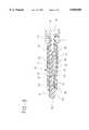
- FIG. 1is an exploded perspective view of the cannula sealing shield assembly of the present invention and a hypodermic syringe.
- FIG. 2is a side elevation view of the cannula sealing shield assembly of the present invention attached to a hypodermic syringe.
- FIG. 3is a cross-sectional view of the cannula assembly and syringe of FIG. 2 taken along line 3--3.
- FIG. 4is the cannula assembly and syringe of FIG. 3 illustrating the seal plug in the proximal cannula sealing position.
- FIG. 5illustrates an alternative needle cannula assembly.
- FIG. 6illustrates a standard hypodermic needle.
- FIGS. 7 and 8are cross-sectional side elevation views of an alternative embodiment of the cannula sealing shield assembly of the present invention.
- FIGS. 9 and 10are cross-sectional side elevation views of still another alternative embodiment of the cannula sealing shield assembly of the present invention.
- FIG. 11is a cross-sectional side elevation view of an alternative embodiment of the present invention wherein the seal plug is capable of sealing the lumen of the cannula.
- FIG. 12is a cross-sectional side elevation view of a cannula sealing shield assembly of the present invention being used with a syringe barrel having a permanently mounted needle cannula.
- a cannula sealing shield assembly 20comprises a cannula assembly 21 including a cannula 22 having a proximal end 23, a distal end 25 and a lumen 27 therethrough.
- a hub 28having an open proximal end 29 and a distal end 31 joined to proximal end 23 of the cannula so that the lumen is in fluid communication with the open proximal end of the hub.
- Hub 28preferably includes radial projections 32 for engaging the locking luer type collar of the syringe barrel or other fluid delivery device, as will be explained in more detail hereinafter.
- distal end 25 of the cannulapreferably includes a blunt tip 33, and the cannula and the hub are preferably integrally formed of a thermoplastic material.
- the cannula and the hubcan be separately formed and later connected mechanically or joined with adhesives such as epoxy.
- a shield 35includes an open proximal end 37, an open distal end 38 and a side wall 39 therebetween defining a recess 40 in the shield.
- the shieldis removably connected to the cannula assembly so that distal end 25 of the cannula is contained within recess 40 of the shield.
- a seal plug 43includes a proximal end 44 and a distal end 45. The seal plug has a distal position, as illustrated in FIG. 3, wherein the seal plug projects distally outwardly from distal end 38 of shield 35 for telescoping movement from the distal position to a proximal position, illustrated in FIG. 4.
- the seal plugincludes means for sealing the cannula to prevent unpressurized fluid from communicating between lumen 27 of the cannula and the exterior of the shield when the seal plug is in the proximal position.
- means for sealingincludes retention conduit 46 extending distally from proximal end 44 of the seal plug.
- the retention conduitincludes an inside surface 47 for sealing engagement with the distal end of the cannula when the seal plug is in the proximal position as illustrated in FIG. 4. It is preferable to include a tapered portion 46 at the proximal end of the seal plug for guiding the distal end of the cannula into the retention conduit when the seal plug is being moved from the distal position to the proximal sealing position.
- seal plug 43in the normal use of the cannula sealing shield assembly, the seal plug cannot be moved from its proximal sealing position through its distal position.
- Means for preventing the seal plug from moving from the proximal sealing position to the distal positioncan be accomplished by a variety of structures and configurations.
- the preferred structureincludes configuring seal plug 43 so that when it is pushed from the distal position of FIG. 3 to the proximal sealing position of FIG. 4 by applying digital pressure to finger contact surface 50, the plug comes to rest substantially inside open distal end 38 of shield 35. In this position, the user is prevented from grasping the plug to pull it back to its distal position.
- interacting structurecan be provided between the shield and the seal plug to help lock the seal plug in the proximal sealing position.
- Such structurecan include projections and/or recesses on the shield to engage projections and/or recesses on the seal plug when the seal plug is in its proximal sealing position, as will be explained in more detail hereinafter.
- the seal plugmay be held in its distal position through mechanical interaction between the shield and the seal plug such as interfering structures, friction, threads or the like.
- the shieldincludes an inwardly directed annular projection 41 and annular recess 51 in the seal plug.
- annular projection 41 in the shieldengages annular recess 5 1 in the seal plug, to hold the seal plug in its desired axial position with respect to the shield.
- the projectionmay be any size from a discrete bump to a full annular ring, or a segmented ring depending on the structural shapes and choice of materials for the plug in the shield.
- the recess in the seal plugcan take a variety of configurations to appropriately interact with the projection in the shield.
- the structurecan also be reversed so that the plug contains the projection and the shield contains the recess.
- the cannula sealing shield assembly of the present inventionis suitable for use with a wide variety of fluid delivery devices such as syringes.
- cannula sealing shield assembly 20is connected to a hypodermic syringe 70 comprising a syringe barrel 71 having a distal end 73, a proximal end 74 and a circular side wall 75 defining a chamber 76 for retaining fluid.
- Volume measuring indicia 72are on the barrel for measuring the amount of fluid to be delivered or received.
- the distal end of the syringe barrelis connected to hub 28 so that the lumen of cannula 22 is in fluid communication with chamber 76 of the syringe barrel.
- distal end 73 of the syringe barrelincludes a preferably frusto-conically shaped tip 77 having a conduit 78 therethrough which provides a fluid path between the cannula and the chamber.
- the frusto-conically shaped tip of the syringe barrelfrictionally engages a preferably frusto-conically shaped surface 30 in open proximal end 29 of the hub.
- the distal end of the syringe barrelalso preferably, but not necessarily, includes a locking luer-type collar 79 concentrically surrounding tip 77.
- the luer collarhas an internal thread 80 which engages the radial projections 32 on hub 28 to hold the hub securely to the barrel.
- a stopper 82is positioned in chamber 76 in sliding fluid-tight engagement with circular side wall 75.
- An elongate plunger rod 83is connected to the stopper and extends proximally through the open proximal end of barrel 71.
- the stopper and the plunger rodcan be made of one-piece unitary construction. The force applied to the plunger rod causing sliding movement of the stopper in a proximal direction draws fluid through the conduit 78 into chamber 76. Conversely, sliding movement of stopper 82 in a distal direction urges fluid from chamber 76 through conduit 78.
- syringe 70can be filled with medication or other liquid through a variety of known methods with the cannula assembly attached or removed. After filling, the syringe and cannula assembly, with shield removed, may be used immediately to deliver medication or other liquid to a patient either directly through the skin or through a pierceable septum of an I.V. set or other device if the distal end of the cannula is sharpened. When the distal end of the cannula is blunt, medication or other liquid can be delivered through various fluid transfer devices including I.V. sets having pre-slit septums which are known in the art.
- the shieldin the embodiment of FIGS.
- the userhas the option of sealing the cannula by moving the seal plug from the distal position to the proximal position. This motion may be accomplished by pressing on the contact surface of the seal plug to move the seal plug in a proximal direction. There may be an extended period of time between filling and syringe and dispensing the medication or liquid. During this time the user may wish to prevent unpressurized fluid from exiting through the distal end of the cannula. By moving the seal plug to the proximal position the cannula is sealed to prevent unpressurized fluid communication between the lumen and the exterior of the shield. At the time of use, the shield is removed to expose the cannula.
- FIG. 5illustrates an alternative cannula assembly 121 including a metal cannula 122, made of metal with stainless steel being preferred, and a hub 128 preferably made of thermoplastic material.
- Cannula 122includes a proximal end 123 and distal end 125, having a lumen therethrough.
- Distal end 125includes a blunt tip 133.
- Cannula assembly 121functions similarly to cannula assembly 21, in the embodiment of FIGS. 1-4.
- Stainless steel cannulaeare desirable because of their strength advantage over thermoplastic cannulae which allow such cannulae to be made in smaller outside diameters and having a large lumen diameter while still having substantial strength.
- FIG. 6illustrates a prior art needle assembly 221 which is commonly used to inject medication into a patient or for transferring fluid through pierceable septums such as septums found in medication vials and I.V. sets.
- Needle assembly 221includes needle cannula 222 having proximal end 223, distal end 225 and a lumen therethrough.
- Needle assembly 221also includes a hub 228 having an open proximal end 229 and a distal end 231 joined to the proximal end of the cannula.
- Distal end 225 of the cannulafurther includes a sharp edge 233 capable of piercing skin, stoppers and septums.
- the preferred embodiment of the cannula sealing shield assembly of the present inventionincludes a cannula assembly having a blunt cannula.
- a cannula sealing shield assemblywhich contains a cannula assembly having a cannula with a sharpened distal tip such as cannula assembly 221.
- FIGS. 7-8illustrate an alternative cannula sealing shield assembly 320 which is functionally similar to the embodiment of FIGS. 1-4.
- cannula sealing shield assembly 320is connected to syringe 370 having an elongate cylindrical body 375 defining a chamber 376 for retaining fluid, an open proximal end, a distal end 373.
- a frusto-conically shaped tip 377extends from the distal end and having a conduit 378 therethrough in fluid communication with chamber 376.
- a cannula assembly 321includes a cannula 322 having a distal end 325 which includes a sharp edge 333.
- a shield 335having an open proximal end 337, an open distal end 338 and a side wall 339 therebetween defining a recess 340 in the shield.
- the shieldis removably connected to the cannula assembly so that the distal end of the cannula is contained within the recess.
- a seal plug 343includes a proximal end 344, having a proximal surface 348 and a distal end 345.
- the seal plughas a distal position wherein the seal plug projects distally outwardly from the distal end of the shield for telescoping movement from the distal position, as illustrated in FIG. 7, to a proximal position, as illustrated in FIG. 8, wherein the seal plug seals the distal end of the cannula to prevent unpressurized fluid communication between the passageway and the exterior of the shield.
- the componentsare configured such that the cannula 322 is long enough so that when seal plug 343 is in the proximal position, as illustrated in FIG.
- the distal end of the cannulais embedded in proximal end 344 of the seal plug.
- embedding the needle portion into the seal plugwill cause the seal plug to sealingly engage the outside surface of the distal end of the cannula, occlude the lumen or both, to prevent unpressurized fluid communication between the lumen and the exterior of the shield.
- the cannula sealing shield assemblyis used in a similar manner to the embodiment of FIGS. 1-4.
- seal plug 343 of the present embodimentAlthough a wide variety of materials can be used to fabricate the seal plug of the present invention, such as, natural rubber, synthetic rubber, thermoplastic elastomer and thermoplastic, softer materials such as natural rubber, synthetic rubber and thermoplastic elastomers are preferred for seal plug 343 of the present embodiment. A softer more resilient material will more easily allow distal end of the cannula to embed itself into the proximal end of the seal plug.
- the seal plugcan be made of two materials, for example, thermoplastic with an elastomeric insert for the proximal surface.
- FIGS. 9 and 10illustrate an alternative cannula sealing shield and syringe assembly.
- This embodimentfunctions similarly to the embodiment of FIGS. 1-4 except that cannula 422 and hub 428 are integrally formed with syringe barrel 471.
- a shield 435has an open proximal end 437, an open distal end 438 and a side wall 439 therebetween defining a recess 440 in the shield.
- a seal plug 434includes a proximal end 444 and a distal end 445. The seal plug has a distal position wherein the seal plug projects distally outwardly from distal open end 438 of the shield, as illustrated in FIG. 9, for telescoping movement from the distal position to a proximal position, as illustrated in FIG. 10.
- FIG. 11illustrates another alternative embodiment of a cannula sealing shield assembly of the present invention.
- This embodimentincludes shield 535 having an open proximal end 537, an open distal end 538 and a side wall 539 therebetween defining a recess 540 in the shield.
- a seal plug 543includes a proximal end 544 and a distal end 545. Sealing plug 543 also includes proximally directed projection 552 on the proximal end of the seal plug.
- Projection 522is configured so that when the seal plug is in the proximal position a portion of projection 522 is in lumen 527 of cannula 522.
- the embodiment of FIG. 11also includes means for preventing movement of the seal plug from the proximal sealing position to the distal position.
- the means for preventing such movementincludes inwardly projecting annular rib 542 in said shield and annular recess 553 in the seal plug.
- FIG. 12illustrates another alternative cannula sealing shield and syringe assembly wherein hypodermic syringe 670 includes a syringe barrel 671 having an elongate cylindrical body or side wall 675 defining a chamber 676 for retaining fluid.
- Barrel 671includes a distal end 673 having a distally projecting tip 677 which includes a tip passageway 681 therethrough in communication with chamber 676.
- a cannula 622includes a distal end 625 and a proximal end 623 which is fixedly attached to tip 677 of the syringe barrel.
- the proximal end of the cannulais positioned within tip passageway 681 and held there by a mechanical means or adhesive such as epoxy.
- the syringe barrelis preferably made of glass or plastic and the cannula is preferably made of metal such as stainless steel and includes a sharp tip 633.
- the assembly of this embodimentfunctions similarly to the assembly of the embodiment of FIG. 11.
Landscapes
- Health & Medical Sciences (AREA)
- Life Sciences & Earth Sciences (AREA)
- Veterinary Medicine (AREA)
- Engineering & Computer Science (AREA)
- Public Health (AREA)
- General Health & Medical Sciences (AREA)
- Animal Behavior & Ethology (AREA)
- Biomedical Technology (AREA)
- Hematology (AREA)
- Heart & Thoracic Surgery (AREA)
- Anesthesiology (AREA)
- Vascular Medicine (AREA)
- Environmental & Geological Engineering (AREA)
- Pharmacology & Pharmacy (AREA)
- Infusion, Injection, And Reservoir Apparatuses (AREA)
- Surgical Instruments (AREA)
Abstract
Description
The present invention relates to a cannula and shield assembly for use with fluid delivery devices such as a hypodermic syringe, and more particularly concerns a shield having cannula sealing features.
A typical hypodermic syringe includes a syringe barrel with a tapered tip extending from its distal end. The syringe is usually used in combination with a needle assembly having a hub and a needle cannula. The hub is configured to engage the tip of the syringe barrel so that the syringe and needle assembly combination can be used to fill the syringe barrel with medication or other liquid for delivery directly to a patient or other fluid delivery apparatus connected to the patient. The prior art teaches a wide variety of needle shields that can be used to re-shield a hypodermic needle after the syringe is filled with medication and before it is delivered to the patient. These shields protect the needle between filling and the time of medication delivery.
The prior art also teaches prefilled syringes having a needle shield lined with elastomeric material which seals the contents of the syringe so that medication cannot leave the syringe through the needle cannula during storage. These needle shields are especially useful in the commercial setting wherein pharmaceutical manufacturers fill syringes which are not used for long periods of time thereafter.
However, there is still a need for a simple cannula and shield assembly which will protect a cannula before use, such as being attached to an empty syringe barrel, wherein the shield has cannula sealing features which can be manually activated by the user after the syringe barrel is filled with medication or other liquid.
The subject invention relates to a cannula sealing shield assembly comprising a cannula, a shield and a seal plug. A cannula assembly includes the cannula having a proximal end, a distal end and a lumen therethrough, and a hub having an open proximal end and a distal end joined to the proximal end of the cannula so that the lumen is in fluid communication with the open proximal end of the hub. The shield has an open proximal end, an open distal end and a side wall therebetween defining a recess in the shield. The shield is removably connected to the cannula assembly so that the distal end of the cannula is contained within the recess. The seal plug has a proximal end and a distal end. The seal plug has a distal position wherein the seal plug projects distally outwardly from the distal end of the shield for telescoping movement from the distal position to a proximal position. The seal plug includes structure for sealing the cannula to prevent unpressurized fluid communication between the lumen of the cannula and the exterior of the seal plug when the seal plug is in the proximal position.
Another embodiment of the present invention includes a cannula sealing shield and syringe assembly comprising a syringe barrel, a cannula, a shield and a seal plug. The syringe barrel has an elongate body defining a chamber for retaining fluid, and open proximal end and a distal end having a tip extending therefrom. The tip includes a passageway therethrough in fluid communication with the chamber. The cannula has a proximal end, a distal end and a lumen therethrough. The proximal end of the cannula is connected to the tip of the syringe barrel so that the lumen is in fluid communication with the chamber. The shield has an open proximal end, an open distal end and a side wall therebetween defining a recess in the shield. The shield is removably connected to the tip of the syringe barrel so that the distal end of the cannula is contained within the recess. The seal plug has a proximal end and a distal end. The seal plug has a distal position with respect to the shield wherein the seal plug projects distally outwardly from the distal end of the shield for telescoping movement from the distal position to a proximal position. The plug includes structure for sealing the cannula to prevent unpressurized fluid communication between the lumen and the exterior of the shield when the plug is in the proximal position.
FIG. 1 is an exploded perspective view of the cannula sealing shield assembly of the present invention and a hypodermic syringe.
FIG. 2 is a side elevation view of the cannula sealing shield assembly of the present invention attached to a hypodermic syringe.
FIG. 3 is a cross-sectional view of the cannula assembly and syringe of FIG. 2 taken alongline 3--3.
FIG. 4 is the cannula assembly and syringe of FIG. 3 illustrating the seal plug in the proximal cannula sealing position.
FIG. 5 illustrates an alternative needle cannula assembly.
FIG. 6 illustrates a standard hypodermic needle.
FIGS. 7 and 8 are cross-sectional side elevation views of an alternative embodiment of the cannula sealing shield assembly of the present invention.
FIGS. 9 and 10 are cross-sectional side elevation views of still another alternative embodiment of the cannula sealing shield assembly of the present invention.
FIG. 11 is a cross-sectional side elevation view of an alternative embodiment of the present invention wherein the seal plug is capable of sealing the lumen of the cannula.
FIG. 12 is a cross-sectional side elevation view of a cannula sealing shield assembly of the present invention being used with a syringe barrel having a permanently mounted needle cannula.
While this invention is satisfied by embodiments in many different forms, there are shown in the drawings and will be herein described in detail preferred embodiments of the invention with the understanding that the present disclosure is to be considered exemplary of the principles of the invention and not intended to limit the scope of the invention to those embodiments illustrated. The scope of the invention will be measured by the appended claims and their equivalents.
Referring to FIGS. 1-4, a cannulasealing shield assembly 20 comprises acannula assembly 21 including acannula 22 having aproximal end 23, adistal end 25 and alumen 27 therethrough. Ahub 28 having an openproximal end 29 and a distal end 31 joined toproximal end 23 of the cannula so that the lumen is in fluid communication with the open proximal end of the hub.Hub 28 preferably includesradial projections 32 for engaging the locking luer type collar of the syringe barrel or other fluid delivery device, as will be explained in more detail hereinafter. In this embodiment,distal end 25 of the cannula preferably includes ablunt tip 33, and the cannula and the hub are preferably integrally formed of a thermoplastic material. However, the cannula and the hub can be separately formed and later connected mechanically or joined with adhesives such as epoxy.
Ashield 35 includes an openproximal end 37, an opendistal end 38 and aside wall 39 therebetween defining arecess 40 in the shield. The shield is removably connected to the cannula assembly so thatdistal end 25 of the cannula is contained withinrecess 40 of the shield. Aseal plug 43 includes aproximal end 44 and adistal end 45. The seal plug has a distal position, as illustrated in FIG. 3, wherein the seal plug projects distally outwardly fromdistal end 38 ofshield 35 for telescoping movement from the distal position to a proximal position, illustrated in FIG. 4. The seal plug includes means for sealing the cannula to prevent unpressurized fluid from communicating betweenlumen 27 of the cannula and the exterior of the shield when the seal plug is in the proximal position. In this embodiment, means for sealing includesretention conduit 46 extending distally fromproximal end 44 of the seal plug. The retention conduit includes aninside surface 47 for sealing engagement with the distal end of the cannula when the seal plug is in the proximal position as illustrated in FIG. 4. It is preferable to include atapered portion 46 at the proximal end of the seal plug for guiding the distal end of the cannula into the retention conduit when the seal plug is being moved from the distal position to the proximal sealing position.
In some applications it is preferable to provide structure or to configure the components so that, in the normal use of the cannula sealing shield assembly, the seal plug cannot be moved from its proximal sealing position through its distal position. Means for preventing the seal plug from moving from the proximal sealing position to the distal position can be accomplished by a variety of structures and configurations. The preferred structure includes configuringseal plug 43 so that when it is pushed from the distal position of FIG. 3 to the proximal sealing position of FIG. 4 by applying digital pressure tofinger contact surface 50, the plug comes to rest substantially inside opendistal end 38 ofshield 35. In this position, the user is prevented from grasping the plug to pull it back to its distal position. Also, interacting structure can be provided between the shield and the seal plug to help lock the seal plug in the proximal sealing position. Such structure can include projections and/or recesses on the shield to engage projections and/or recesses on the seal plug when the seal plug is in its proximal sealing position, as will be explained in more detail hereinafter.
The seal plug may be held in its distal position through mechanical interaction between the shield and the seal plug such as interfering structures, friction, threads or the like. In this embodiment, the shield includes an inwardly directedannular projection 41 and annular recess 51 in the seal plug. When the seal plug is in its distal position, as illustrated in FIG. 3,annular projection 41 in the shield engages annular recess 5 1 in the seal plug, to hold the seal plug in its desired axial position with respect to the shield. The projection may be any size from a discrete bump to a full annular ring, or a segmented ring depending on the structural shapes and choice of materials for the plug in the shield. Likewise, the recess in the seal plug can take a variety of configurations to appropriately interact with the projection in the shield. The structure can also be reversed so that the plug contains the projection and the shield contains the recess.
The cannula sealing shield assembly of the present invention is suitable for use with a wide variety of fluid delivery devices such as syringes. For the purpose of illustration, cannula sealingshield assembly 20 is connected to ahypodermic syringe 70 comprising asyringe barrel 71 having adistal end 73, aproximal end 74 and acircular side wall 75 defining achamber 76 for retaining fluid.Volume measuring indicia 72 are on the barrel for measuring the amount of fluid to be delivered or received. The distal end of the syringe barrel is connected tohub 28 so that the lumen ofcannula 22 is in fluid communication withchamber 76 of the syringe barrel. In this embodiment,distal end 73 of the syringe barrel includes a preferably frusto-conically shapedtip 77 having aconduit 78 therethrough which provides a fluid path between the cannula and the chamber. The frusto-conically shaped tip of the syringe barrel frictionally engages a preferably frusto-conically shapedsurface 30 in openproximal end 29 of the hub. The distal end of the syringe barrel also preferably, but not necessarily, includes a locking luer-type collar 79 concentrically surroundingtip 77. The luer collar has an internal thread 80 which engages theradial projections 32 onhub 28 to hold the hub securely to the barrel. It is within the scope of the present invention to include various hub configurations to attach to a variety of medical fluid handling devices. The hub configuration described hereinabove, having a frusto-conically shaped interior cavity, reflects one of these many possibilities. Many syringes and fluid handling devices, such as stopcocks and adapters, contain a luer slip or locking luer-type fittings to which a hub having a frusto-conically shaped interior cavity will properly engage. It is within the purview of the present invention to provide a cannula sealing shield and syringe assembly wherein the cannula assembly is integrally molded with the syringe barrel. It is also within the purview of the present invention to provide such an assembly wherein the cannula is permanently attached to the tip of the syringe barrel.
Astopper 82 is positioned inchamber 76 in sliding fluid-tight engagement withcircular side wall 75. Anelongate plunger rod 83 is connected to the stopper and extends proximally through the open proximal end ofbarrel 71. The stopper and the plunger rod can be made of one-piece unitary construction. The force applied to the plunger rod causing sliding movement of the stopper in a proximal direction draws fluid through theconduit 78 intochamber 76. Conversely, sliding movement ofstopper 82 in a distal direction urges fluid fromchamber 76 throughconduit 78.
In use,syringe 70 can be filled with medication or other liquid through a variety of known methods with the cannula assembly attached or removed. After filling, the syringe and cannula assembly, with shield removed, may be used immediately to deliver medication or other liquid to a patient either directly through the skin or through a pierceable septum of an I.V. set or other device if the distal end of the cannula is sharpened. When the distal end of the cannula is blunt, medication or other liquid can be delivered through various fluid transfer devices including I.V. sets having pre-slit septums which are known in the art. The shield, in the embodiment of FIGS. 1-4, can be removed and installed as many times as necessary between filling the syringe and delivering medication or other liquid to the patient. It is an important feature of the present invention that the user has the option of sealing the cannula by moving the seal plug from the distal position to the proximal position. This motion may be accomplished by pressing on the contact surface of the seal plug to move the seal plug in a proximal direction. There may be an extended period of time between filling and syringe and dispensing the medication or liquid. During this time the user may wish to prevent unpressurized fluid from exiting through the distal end of the cannula. By moving the seal plug to the proximal position the cannula is sealed to prevent unpressurized fluid communication between the lumen and the exterior of the shield. At the time of use, the shield is removed to expose the cannula.
FIG. 5 illustrates analternative cannula assembly 121 including ametal cannula 122, made of metal with stainless steel being preferred, and ahub 128 preferably made of thermoplastic material.Cannula 122 includes aproximal end 123 anddistal end 125, having a lumen therethrough.Distal end 125 includes ablunt tip 133.Cannula assembly 121 functions similarly tocannula assembly 21, in the embodiment of FIGS. 1-4. Stainless steel cannulae are desirable because of their strength advantage over thermoplastic cannulae which allow such cannulae to be made in smaller outside diameters and having a large lumen diameter while still having substantial strength.
FIG. 6 illustrates a prior art needle assembly 221 which is commonly used to inject medication into a patient or for transferring fluid through pierceable septums such as septums found in medication vials and I.V. sets. Needle assembly 221 includesneedle cannula 222 havingproximal end 223,distal end 225 and a lumen therethrough. Needle assembly 221 also includes ahub 228 having an openproximal end 229 and adistal end 231 joined to the proximal end of the cannula.Distal end 225 of the cannula further includes asharp edge 233 capable of piercing skin, stoppers and septums.
The preferred embodiment of the cannula sealing shield assembly of the present invention includes a cannula assembly having a blunt cannula. However, it is within the purview of the present invention to include a cannula sealing shield assembly which contains a cannula assembly having a cannula with a sharpened distal tip such as cannula assembly 221.
FIGS. 7-8 illustrate an alternative cannula sealingshield assembly 320 which is functionally similar to the embodiment of FIGS. 1-4. For the purposes of illustration, cannula sealingshield assembly 320 is connected tosyringe 370 having an elongatecylindrical body 375 defining achamber 376 for retaining fluid, an open proximal end, a distal end 373. A frusto-conicallyshaped tip 377 extends from the distal end and having aconduit 378 therethrough in fluid communication withchamber 376. Acannula assembly 321 includes acannula 322 having adistal end 325 which includes asharp edge 333. Ashield 335 having an openproximal end 337, an opendistal end 338 and aside wall 339 therebetween defining arecess 340 in the shield. The shield is removably connected to the cannula assembly so that the distal end of the cannula is contained within the recess.
Aseal plug 343 includes aproximal end 344, having aproximal surface 348 and adistal end 345. The seal plug has a distal position wherein the seal plug projects distally outwardly from the distal end of the shield for telescoping movement from the distal position, as illustrated in FIG. 7, to a proximal position, as illustrated in FIG. 8, wherein the seal plug seals the distal end of the cannula to prevent unpressurized fluid communication between the passageway and the exterior of the shield. In this embodiment, the components are configured such that thecannula 322 is long enough so that whenseal plug 343 is in the proximal position, as illustrated in FIG. 8, the distal end of the cannula is embedded inproximal end 344 of the seal plug. Depending on the shape of thesharp edge 333 of the distal end of the cannula and the configuration and material of the seal plug, embedding the needle portion into the seal plug will cause the seal plug to sealingly engage the outside surface of the distal end of the cannula, occlude the lumen or both, to prevent unpressurized fluid communication between the lumen and the exterior of the shield. The cannula sealing shield assembly is used in a similar manner to the embodiment of FIGS. 1-4.
Although a wide variety of materials can be used to fabricate the seal plug of the present invention, such as, natural rubber, synthetic rubber, thermoplastic elastomer and thermoplastic, softer materials such as natural rubber, synthetic rubber and thermoplastic elastomers are preferred forseal plug 343 of the present embodiment. A softer more resilient material will more easily allow distal end of the cannula to embed itself into the proximal end of the seal plug. The seal plug can be made of two materials, for example, thermoplastic with an elastomeric insert for the proximal surface.
FIGS. 9 and 10 illustrate an alternative cannula sealing shield and syringe assembly. This embodiment functions similarly to the embodiment of FIGS. 1-4 except thatcannula 422 andhub 428 are integrally formed withsyringe barrel 471. Ashield 435 has an openproximal end 437, an opendistal end 438 and aside wall 439 therebetween defining arecess 440 in the shield. Aseal plug 434 includes aproximal end 444 and adistal end 445. The seal plug has a distal position wherein the seal plug projects distally outwardly from distalopen end 438 of the shield, as illustrated in FIG. 9, for telescoping movement from the distal position to a proximal position, as illustrated in FIG. 10.
FIG. 11 illustrates another alternative embodiment of a cannula sealing shield assembly of the present invention. This embodiment includesshield 535 having an openproximal end 537, an opendistal end 538 and aside wall 539 therebetween defining arecess 540 in the shield. Aseal plug 543 includes aproximal end 544 and adistal end 545.Sealing plug 543 also includes proximally directedprojection 552 on the proximal end of the seal plug.Projection 522 is configured so that when the seal plug is in the proximal position a portion ofprojection 522 is inlumen 527 ofcannula 522. The embodiment of FIG. 11 also includes means for preventing movement of the seal plug from the proximal sealing position to the distal position. In this embodiment the means for preventing such movement includes inwardly projectingannular rib 542 in said shield andannular recess 553 in the seal plug. When the seal plug is moved to its proximal cannula sealing position, by applying pressure to fingercontact surface 550, inwardly projectingannular rib 542 snaps intoannular recess 553 to lock the seal plug in the proximal position.
FIG. 12 illustrates another alternative cannula sealing shield and syringe assembly whereinhypodermic syringe 670 includes asyringe barrel 671 having an elongate cylindrical body orside wall 675 defining achamber 676 for retaining fluid.Barrel 671 includes adistal end 673 having a distally projectingtip 677 which includes atip passageway 681 therethrough in communication withchamber 676. Acannula 622 includes adistal end 625 and aproximal end 623 which is fixedly attached to tip 677 of the syringe barrel. In this embodiment the proximal end of the cannula is positioned withintip passageway 681 and held there by a mechanical means or adhesive such as epoxy. In this embodiment, the syringe barrel is preferably made of glass or plastic and the cannula is preferably made of metal such as stainless steel and includes asharp tip 633. In use, the assembly of this embodiment functions similarly to the assembly of the embodiment of FIG. 11.
Claims (19)
1. A cannula sealing shield assembly comprising:
a cannula assembly including a cannula having a proximal end, a distal end and a lumen therethrough, and a hub having an open proximal end and a distal end joined to said proximal end of said cannula so that said lumen is in fluid communication with said open proximal end of said hub;
a shield having an open proximal end, an open distal end and a side wall therebetween defining a recess in said shield, said shield being removably connected to said cannula assembly so that said distal end of said cannula is contained within said recess; and
a seal plug having a proximal end and a distal end, said seal plug having a distal position wherein said seal plug projects distally outwardly from said distal end of said shield for telescoping movement from said distal position to a proximal position, said seal plug including means for sealing said cannula to prevent unpressurized fluid communication between said lumen and the exterior of said shield when said seal plug is in said proximal position.
2. The cannula sealing shield assembly of claim 1 wherein said means for sealing includes a retention conduit extending distally from said proximal end of said seal plug, said conduit having an inside surface for sealing engagement with said distal end of said cannula when said sealing plug is in said proximal position.
3. The cannula sealing shield assembly of claim 2 wherein said seal plug includes a tapered portion at said proximal end for guiding said distal end of said cannula into said retention conduit when said seal plug is being moved from said distal position to said proximal position.
4. The cannula sealing shield assembly of claim 1 wherein said sealing means includes said cannula being long enough so that when said seal plug is in said proximal position said distal end of said cannula is embedded in said proximal end of said seal plug.
5. The cannula sealing shield assembly of claim 1 wherein said means for sealing includes a proximally directed projection on said proximal end of said seal plug, said projection being configured so that when said seal plug is in said proximal position a portion of said projection is in said lumen of said cannula.
6. The cannula sealing shield assembly of claim 1 wherein said seal plug is made of material selected from the group consisting of natural rubber, synthetic rubber, thermoplastic elastomer and thermoplastic.
7. The cannula sealing shield assembly of claim 1 further including means for preventing said seal plug from moving from said proximal sealing position to said distal position.
8. The cannula sealing shield assembly of claim 1 wherein said distal end of said cannula includes a blunt distal tip.
9. The cannula sealing shield assembly of claim 1 wherein said cannula and said hub are integrally formed of thermoplastic material.
10. The cannula sealing shield assembly of claim 1 wherein said cannula is made of metal.
11. The cannula sealing shield assembly of claim 1 further including a syringe barrel having an elongate cylindrical body defining a chamber for retaining fluid, an open proximal end, a distal end and a tip extending from said distal end having a tip passageway therethrough in fluid communication with said chamber, said tip being positioned within said open proximal end of said hub so that said chamber is in fluid communication with said lumen of said cannula.
12. The cannula sealing shield assembly of claim 11 wherein said syringe barrel further includes a stopper positioned in said chamber in sliding fluid-tight engagement with said side wall and an elongate plunger rod connected to said stopper and extending proximally outwardly through said open proximal end of said barrel so that force applied to said plunger rod causing sliding movement of said stopper in a proximal direction draws fluid through said tip passageway into said chamber and sliding movement of said stopper in a distal direction urges fluid from said chamber through said tip passageway.
13. The cannula sealing shield assembly of claim 1 wherein said cannula assembly is integrally formed with a syringe barrel having an elongate cylindrical body defining a chamber for retaining fluid, an open proximal end and a distal end, said cannula extending from said distal end of said barrel and positioned so that said lumen of said cannula is in fluid communication with said chamber.
14. A cannula sealing shield assembly comprising:
a cannula assembly including a cannula having a proximal end, a blunt distal end and a lumen therethrough, and a hub having an open proximal end and a distal end joined to said proximal end of said cannula so that said lumen is in fluid communication with said open proximal end of said hub;
a shield having an open proximal end, an open distal end and a side wall therebetween defining a recess in said shield, said shield being removably connected to said cannula assembly so that said distal end of said cannula is contained within said recess; and
a seal plug having a proximal end and a distal end, said seal plug having a distal position wherein said seal plug projects distally outwardly from said distal end of said shield for telescoping movement from said distal position to a proximal position, said seal plug including means for sealing said cannula to prevent unpressurized fluid communication between said lumen and the exterior of said shield when said seal plug is in said proximal position, said means for sealing including a retention conduit extending distally from said proximal end of said seal plug, said conduit having an inside surface for sealing engagement with said needle portion when said sealing plug is in said proximal position.
15. A cannula sealing shield and syringe assembly comprising:
a syringe barrel having an elongate body defining a chamber for retaining fluid, an open proximal end, a distal end, and a tip extending from said distal end having a tip passageway therethrough in fluid communication with said chamber;
a cannula having a proximal end, a distal end and a lumen therethrough, said proximal end of said cannula being connected to said tip so that said lumen is in fluid communication with said chamber;
a shield having an open proximal end, an open distal end and a side wall therebetween defining a recess in said shield, said shield being removably connected to said tip of said syringe barrel so that said distal end of said cannula is contained within said recess; and
a seal plug having a proximal end and a distal end, said seal plug having a distal position wherein said seal plug projects distally outwardly from said distal end of said shield for a telescoping movement from said distal position to a proximal position, said plug including means for sealing said cannula to prevent unpressurized fluid communication between said lumen and the exterior of said shield when said seal plug is in said proximal position.
16. The cannula sealing shield and syringe assembly of claim 15 wherein said means for sealing includes a retention conduit extending distally from said proximal end of said seal plug, said conduit having an inside surface for sealing engagement with said distal end of said cannula when said sealing plug is in said proximal position.
17. The cannula sealing shield and syringe assembly of claim 16 wherein said seal plug includes a tapered portion at said proximal end for guiding said distal end of said cannula into said retention conduit when said seal plug is being moved from said distal position to said proximal position.
18. A cannula sealing shield and syringe assembly wherein said cannula is made of metal.
19. A cannula sealing shield and syringe assembly wherein said syringe barrel is made of material selected from the group of thermoplastic and glass.
Priority Applications (15)
| Application Number | Priority Date | Filing Date | Title |
|---|---|---|---|
| US08/839,223US5858008A (en) | 1997-04-22 | 1997-04-22 | Cannula sealing shield assembly |
| TW86109381ATW410164B (en) | 1997-04-22 | 1997-07-03 | Cannula sealing shield assembly |
| CA 2209956CA2209956C (en) | 1997-04-22 | 1997-07-04 | Cannula sealing shield assembly |
| CA 2209957CA2209957C (en) | 1996-07-22 | 1997-07-04 | Syringe filling and delivery device |
| JP09188609AJP3083134B2 (en) | 1997-04-22 | 1997-07-14 | Cannula sealed shield assembly |
| DE69715747TDE69715747T2 (en) | 1996-07-22 | 1997-07-15 | Device for filling and administering the contents of syringes |
| EP19970305220EP0873757B1 (en) | 1997-04-22 | 1997-07-15 | Cannula sealing shield assembly |
| DE1997625282DE69725282T2 (en) | 1997-04-22 | 1997-07-15 | Sealing and protective arrangement for cannulas |
| EP19970305249EP0820779B1 (en) | 1996-07-22 | 1997-07-15 | Syringe filling and delivery device |
| ES97305249TES2184035T3 (en) | 1996-07-22 | 1997-07-15 | DEVICE FOR FILLING AND MANAGING THE CONTENT OF SYRINGES. |
| SG1997002473ASG66379A1 (en) | 1997-04-22 | 1997-07-16 | Cannula sealing shield assembly |
| BR9704042ABR9704042A (en) | 1997-04-22 | 1997-07-21 | Cannula seal protector set |
| MXPA/A/1997/005523AMXPA97005523A (en) | 1997-04-22 | 1997-07-21 | Can sealing protector assembly |
| AU29435/97AAU735857B2 (en) | 1997-04-22 | 1997-07-22 | Cannula sealing shield assembly |
| KR1019970034270AKR100408924B1 (en) | 1997-04-22 | 1997-07-22 | Cannula seal seal assembly |
Applications Claiming Priority (1)
| Application Number | Priority Date | Filing Date | Title |
|---|---|---|---|
| US08/839,223US5858008A (en) | 1997-04-22 | 1997-04-22 | Cannula sealing shield assembly |
Publications (1)
| Publication Number | Publication Date |
|---|---|
| US5858008Atrue US5858008A (en) | 1999-01-12 |
Family
ID=25279180
Family Applications (1)
| Application Number | Title | Priority Date | Filing Date |
|---|---|---|---|
| US08/839,223Expired - LifetimeUS5858008A (en) | 1996-07-22 | 1997-04-22 | Cannula sealing shield assembly |
Country Status (10)
| Country | Link |
|---|---|
| US (1) | US5858008A (en) |
| EP (1) | EP0873757B1 (en) |
| JP (1) | JP3083134B2 (en) |
| KR (1) | KR100408924B1 (en) |
| AU (1) | AU735857B2 (en) |
| BR (1) | BR9704042A (en) |
| CA (1) | CA2209956C (en) |
| DE (1) | DE69725282T2 (en) |
| SG (1) | SG66379A1 (en) |
| TW (1) | TW410164B (en) |
Cited By (92)
| Publication number | Priority date | Publication date | Assignee | Title |
|---|---|---|---|---|
| USD454394S1 (en) | 2001-03-19 | 2002-03-12 | Becton Dickinson And Company | Needle cover |
| WO2001056632A3 (en)* | 2000-02-02 | 2002-03-14 | Fada Italia S P A | Improved disposable syringe |
| US6440151B1 (en) | 1998-05-01 | 2002-08-27 | Sub-Q, Inc. | Device and method for facilitating hemostasis of a biopsy tract |
| US6447534B2 (en) | 1998-05-01 | 2002-09-10 | Sub-Q, Inc. | Device and method for facilitating hemostasis of a biopsy tract |
| US20020156495A1 (en)* | 1995-09-15 | 2002-10-24 | Rodney Brenneman | Apparatus and method for percutaneous sealing of blood vessel punctures |
| US20020190226A1 (en)* | 2001-03-12 | 2002-12-19 | Mark Ashby | Methods for sterilizing cross-linked gelatin compositions |
| US20030028140A1 (en)* | 2001-03-12 | 2003-02-06 | Greff Richard J. | Cross-linked gelatin composition comprising a wetting agent |
| US20030088271A1 (en)* | 1998-05-01 | 2003-05-08 | Cragg Andrew M. | System and method for facilitating hemostasis of blood vessel punctures with absorbable sponge |
| US20030135237A1 (en)* | 1998-05-01 | 2003-07-17 | Cragg Andrew H. | Device, system and method for improving delivery of hemostatic material |
| US6610026B2 (en) | 1998-05-01 | 2003-08-26 | Sub-Q, Inc. | Method of hydrating a sponge material for delivery to a body |
| US6629963B2 (en)* | 1996-06-20 | 2003-10-07 | Becton, Dickinson And Company | Syringe and needle shield assembly and method of sterilizing such assembly |
| US20040019330A1 (en)* | 2001-11-08 | 2004-01-29 | Sub-Q, Inc., A California Corporation | Sheath based blood vessel puncture locator and depth indicator |
| US6702785B1 (en)* | 2000-05-04 | 2004-03-09 | Collins Sonya Dene | Needle capper |
| US20040102730A1 (en)* | 2002-10-22 | 2004-05-27 | Davis Thomas P. | System and method for facilitating hemostasis of blood vessel punctures with absorbable sponge |
| US20040111066A1 (en)* | 1996-06-20 | 2004-06-10 | Becton, Dickinson And Company | Mult-beveled point needle and syringe having a multi-beveled point needle |
| US20040176723A1 (en)* | 2001-11-08 | 2004-09-09 | Sing Eduardo Chi | Pledget-handling system and method for delivering hemostasis promoting material to a blood vessel puncture site by fluid pressure |
| US6846320B2 (en) | 1998-05-01 | 2005-01-25 | Sub-Q, Inc. | Device and method for facilitating hemostasis of a biopsy tract |
| US20050033360A1 (en)* | 2001-11-08 | 2005-02-10 | Sing Eduardo Chi | Pledget-handling system and method for delivering hemostasis promoting material to a blood vessel puncture site by fluid pressure |
| US6863680B2 (en) | 2001-11-08 | 2005-03-08 | Sub-Q, Inc. | System and method for delivering hemostasis promoting material to a blood vessel puncture site by fluid pressure |
| US20050059080A1 (en)* | 1998-05-01 | 2005-03-17 | Sing Eduardo Chi | Absorbable sponge with contrasting agent |
| US20050196553A1 (en)* | 1997-07-11 | 2005-09-08 | Weder Donald E. | Method for producing corrugated decorative grass |
| US20050222539A1 (en)* | 2004-03-30 | 2005-10-06 | Pediamed Pharmaceuticals, Inc. | Automatic injection device |
| US6964658B2 (en) | 2000-05-12 | 2005-11-15 | Sub-Q, Inc. | System and method for facilitating hemostasis of blood vessel punctures with absorbable sponge |
| US6984219B2 (en) | 1999-09-23 | 2006-01-10 | Mark Ashby | Depth and puncture control for blood vessel hemostasis system |
| US7008440B2 (en) | 2001-11-08 | 2006-03-07 | Sub-Q, Inc. | System and method for delivering hemostasis promoting material to a blood vessel puncture site by fluid pressure |
| US7029489B1 (en) | 2001-05-18 | 2006-04-18 | Sub-Q, Inc. | System and method for delivering hemostasis promoting material to a blood vessel puncture site |
| US7037322B1 (en) | 2001-11-08 | 2006-05-02 | Sub-Q, Inc. | System and method for delivering hemostasis promoting material to a blood vessel puncture with a staging tube |
| US7048710B1 (en) | 1998-05-01 | 2006-05-23 | Sub-Q, Inc. | System and method for facilitating hemostasis of blood vessel punctures with absorbable sponge |
| US7201725B1 (en) | 2000-09-25 | 2007-04-10 | Sub-Q, Inc. | Device and method for determining a depth of an incision |
| US7335219B1 (en) | 2002-11-04 | 2008-02-26 | Sub-Q, Inc. | Hemostatic device including a capsule |
| US20090182284A1 (en)* | 2008-01-11 | 2009-07-16 | Ucb Pharma Sa | Systems and methods for administering medication |
| US7625352B1 (en) | 1998-05-01 | 2009-12-01 | Sub-Q, Inc. | Depth and puncture control for system for hemostasis of blood vessel |
| US20090326467A1 (en)* | 2008-06-25 | 2009-12-31 | Tyco Healthcare Group Lp | Surgical portal apparatus with waffle seal |
| US7695492B1 (en) | 1999-09-23 | 2010-04-13 | Boston Scientific Scimed, Inc. | Enhanced bleed back system |
| US20100160889A1 (en)* | 2008-12-22 | 2010-06-24 | Baxter International Inc. | Vial access spike assembly |
| US20100198163A1 (en)* | 2007-03-02 | 2010-08-05 | Bonnet Stephane | Protection device for a needle |
| US7875043B1 (en) | 2003-12-09 | 2011-01-25 | Sub-Q, Inc. | Cinching loop |
| US20110112622A1 (en)* | 2009-05-29 | 2011-05-12 | Xlumena, Inc. | Apparatus and method for deploying stent across adjacent tissue layers |
| US7955353B1 (en) | 2002-11-04 | 2011-06-07 | Sub-Q, Inc. | Dissolvable closure device |
| USD641078S1 (en) | 2008-12-29 | 2011-07-05 | Ucb Pharma, S.A. | Medical syringe with needle tip cap |
| WO2011098831A1 (en)* | 2010-02-11 | 2011-08-18 | Barry Peter Liversidge | Medical needle cover arrangement |
| USD660958S1 (en) | 2009-07-20 | 2012-05-29 | Ucb Pharma, S.A. | Device for administering medication |
| US8317821B1 (en) | 2002-11-04 | 2012-11-27 | Boston Scientific Scimed, Inc. | Release mechanism |
| US8512295B2 (en) | 2010-08-19 | 2013-08-20 | West Pharmaceutical Services, Inc. | Rigid needle shield |
| EP2575929A4 (en)* | 2010-06-03 | 2014-12-17 | Jms North America Corp | Systems and methods for a medical syringe |
| US8945067B2 (en) | 2008-07-18 | 2015-02-03 | Ucb Pharma, S.A. | Systems for administering medication |
| US9072827B2 (en) | 2012-03-26 | 2015-07-07 | Medimop Medical Projects Ltd. | Fail safe point protector for needle safety flap |
| US9149575B2 (en) | 2010-01-19 | 2015-10-06 | Medimop Medical Projects Ltd. | Needle assembly for drug pump |
| US9166313B2 (en) | 2013-04-30 | 2015-10-20 | Medimop Medical Projects | Power supply contact for installation of printed circuit board |
| US9173997B2 (en) | 2007-10-02 | 2015-11-03 | Medimop Medical Projects Ltd. | External drug pump |
| USD747799S1 (en) | 2011-03-22 | 2016-01-19 | Medimop Medical Projects Ltd. | Cartridge |
| US9259532B2 (en) | 2010-01-19 | 2016-02-16 | Medimop Medical Projects Ltd. | Cartridge interface assembly |
| US9345836B2 (en) | 2007-10-02 | 2016-05-24 | Medimop Medical Projects Ltd. | Disengagement resistant telescoping assembly and unidirectional method of assembly for such |
| US9421323B2 (en) | 2013-01-03 | 2016-08-23 | Medimop Medical Projects Ltd. | Door and doorstop for portable one use drug delivery apparatus |
| US9452261B2 (en) | 2010-05-10 | 2016-09-27 | Medimop Medical Projects Ltd. | Low volume accurate injector |
| US9463280B2 (en) | 2012-03-26 | 2016-10-11 | Medimop Medical Projects Ltd. | Motion activated septum puncturing drug delivery device |
| US9572926B2 (en) | 2009-09-15 | 2017-02-21 | Medimop Medical Projects Ltd. | Cartridge insertion assembly |
| US9656019B2 (en) | 2007-10-02 | 2017-05-23 | Medimop Medical Projects Ltd. | Apparatuses for securing components of a drug delivery system during transport and methods of using same |
| US9744297B2 (en) | 2015-04-10 | 2017-08-29 | Medimop Medical Projects Ltd. | Needle cannula position as an input to operational control of an injection device |
| US9795534B2 (en) | 2015-03-04 | 2017-10-24 | Medimop Medical Projects Ltd. | Compliant coupling assembly for cartridge coupling of a drug delivery device |
| US9889256B2 (en) | 2013-05-03 | 2018-02-13 | Medimop Medical Projects Ltd. | Sensing a status of an infuser based on sensing motor control and power input |
| US9987432B2 (en) | 2015-09-22 | 2018-06-05 | West Pharma. Services IL, Ltd. | Rotation resistant friction adapter for plunger driver of drug delivery device |
| US10071196B2 (en) | 2012-05-15 | 2018-09-11 | West Pharma. Services IL, Ltd. | Method for selectively powering a battery-operated drug-delivery device and device therefor |
| US10071198B2 (en) | 2012-11-02 | 2018-09-11 | West Pharma. Servicees IL, Ltd. | Adhesive structure for medical device |
| USD835268S1 (en)* | 2017-04-06 | 2018-12-04 | Becton, Dickinson And Company | Syringe tip with indicator |
| USD835269S1 (en)* | 2017-04-06 | 2018-12-04 | Becton, Dickinson And Company | Syringe tip with indicator |
| US10149943B2 (en) | 2015-05-29 | 2018-12-11 | West Pharma. Services IL, Ltd. | Linear rotation stabilizer for a telescoping syringe stopper driverdriving assembly |
| US10251813B2 (en) | 2015-03-04 | 2019-04-09 | West Pharma. Services IL, Ltd. | Flexibly mounted cartridge alignment collar for drug delivery device |
| US10293120B2 (en) | 2015-04-10 | 2019-05-21 | West Pharma. Services IL, Ltd. | Redundant injection device status indication |
| US10335545B2 (en) | 2012-01-31 | 2019-07-02 | West Pharma. Services IL, Ltd. | Time dependent drug delivery apparatus |
| US10363377B2 (en) | 2014-12-03 | 2019-07-30 | Eli Lilly And Company | Needle shield puller cap assembly |
| US10420880B2 (en) | 2007-10-02 | 2019-09-24 | West Pharma. Services IL, Ltd. | Key for securing components of a drug delivery system during assembly and/or transport and methods of using same |
| US10668213B2 (en) | 2012-03-26 | 2020-06-02 | West Pharma. Services IL, Ltd. | Motion activated mechanisms for a drug delivery device |
| US10857343B2 (en) | 2017-04-06 | 2020-12-08 | Becton, Dickinson And Company | Medical devices with visual and tactile indicators |
| US11013865B2 (en) | 2013-10-15 | 2021-05-25 | Becton Dickinson France | Tip cap assembly for closing an injection system |
| US11167086B2 (en) | 2008-09-15 | 2021-11-09 | West Pharma. Services IL, Ltd. | Stabilized pen injector |
| US11311674B2 (en) | 2016-01-21 | 2022-04-26 | West Pharma. Services IL, Ltd. | Medicament delivery device comprising a visual indicator |
| US11318254B2 (en) | 2015-10-09 | 2022-05-03 | West Pharma. Services IL, Ltd. | Injector needle cap remover |
| US11338090B2 (en) | 2016-08-01 | 2022-05-24 | West Pharma. Services IL, Ltd. | Anti-rotation cartridge pin |
| US11364337B2 (en) | 2016-01-21 | 2022-06-21 | West Pharma. Services IL, Ltd. | Force containment in an automatic injector |
| US11389597B2 (en) | 2016-03-16 | 2022-07-19 | West Pharma. Services IL, Ltd. | Staged telescopic screw assembly having different visual indicators |
| WO2022175249A1 (en)* | 2021-02-16 | 2022-08-25 | Novo Nordisk A/S | Needle assembly with sealing feature |
| US11484662B2 (en)* | 2015-11-27 | 2022-11-01 | Sanofi-Aventis Deutschland Gmbh | Medicament injection device |
| US11547802B2 (en) | 2015-10-09 | 2023-01-10 | West Pharma. Services IL, Ltd. | Angled syringe patch injector |
| US11672904B2 (en) | 2016-01-21 | 2023-06-13 | West Pharma. Services IL, Ltd. | Needle insertion and retraction mechanism |
| US11730892B2 (en) | 2016-08-01 | 2023-08-22 | West Pharma. Services IL, Ltd. | Partial door closure prevention spring |
| US11819673B2 (en) | 2016-06-02 | 2023-11-21 | West Pharma. Services, IL, Ltd. | Three position needle retraction |
| US11819666B2 (en) | 2017-05-30 | 2023-11-21 | West Pharma. Services IL, Ltd. | Modular drive train for wearable injector |
| US11857767B2 (en) | 2017-12-22 | 2024-01-02 | West Pharma. Services IL, Ltd. | Injector usable with different dimension cartridges |
| US11931552B2 (en) | 2015-06-04 | 2024-03-19 | West Pharma Services Il, Ltd. | Cartridge insertion for drug delivery device |
| US12097357B2 (en) | 2008-09-15 | 2024-09-24 | West Pharma. Services IL, Ltd. | Stabilized pen injector |
| USD1071214S1 (en)* | 2024-07-15 | 2025-04-15 | Jonathan D. Hodges | Needle capper |
Families Citing this family (6)
| Publication number | Priority date | Publication date | Assignee | Title |
|---|---|---|---|---|
| DE19927201A1 (en)* | 1999-06-15 | 2001-01-25 | Schott Glas | Syringe for medical purposes |
| AU1569301A (en)* | 1999-11-05 | 2001-06-06 | Eli Lilly And Company | Teat infusion syringe and related components |
| US6951228B2 (en)* | 2003-12-04 | 2005-10-04 | B Braun Medical Inc. | Bulk compounder manifold |
| JP5725838B2 (en)* | 2010-12-20 | 2015-05-27 | 三菱鉛筆株式会社 | Needle tip sealing device for blood collection device |
| JP5615158B2 (en)* | 2010-12-20 | 2014-10-29 | 三菱鉛筆株式会社 | Needle tip sealing device for blood collection device |
| CN111359055A (en)* | 2020-03-18 | 2020-07-03 | 江西洪达医疗器械集团有限公司 | Easy-to-feed gas cylinder plug puncture outfit |
Citations (2)
| Publication number | Priority date | Publication date | Assignee | Title |
|---|---|---|---|---|
| US5085647A (en)* | 1991-03-07 | 1992-02-04 | Sherwood Medical Company | Rigid needle cover with needle sealing plug and method of manufacture thereof |
| US5624402A (en)* | 1994-12-12 | 1997-04-29 | Becton, Dickinson And Company | Syringe tip cap |
Family Cites Families (10)
| Publication number | Priority date | Publication date | Assignee | Title |
|---|---|---|---|---|
| DE1057737B (en)* | 1955-05-03 | 1959-05-21 | Gruenenthal Chemie | Injection ampoule for multiple media and single use |
| US4781701A (en)* | 1986-07-11 | 1988-11-01 | Arzneimittel Gmbh Apotheker Vetter & Co. Ravensburg | Syringe for medical purposes |
| US4728321A (en) | 1987-04-16 | 1988-03-01 | Ming-Chiu Wu | Syringe cap with adhesive holding plug |
| US4872552A (en)* | 1988-11-16 | 1989-10-10 | Mid-South Products Engineering, Inc. | Safety packaging for hypodermic syringes with needles and the like |
| US4964866A (en)* | 1989-11-22 | 1990-10-23 | Becton, Dickinson And Company | Needle sheath assembly |
| US5116325A (en)* | 1990-06-06 | 1992-05-26 | Paterson Donald W | Needle assembly |
| US5232455A (en)* | 1991-01-07 | 1993-08-03 | Smiths Industries Medical Systems, Inc. | Syringe with protective housing |
| US5242400A (en)* | 1991-12-06 | 1993-09-07 | The Medtech Group, Inc. | Disposable pre-filled syringe with retractable needle |
| US5540666A (en)* | 1993-03-31 | 1996-07-30 | Immuno Aktiengesellschaft | Cannula shield and injection syringe system |
| DE69506017T2 (en)* | 1994-03-17 | 1999-10-07 | Terumo K.K., Tokio/Tokyo | Resin needle |
- 1997
- 1997-04-22USUS08/839,223patent/US5858008A/ennot_activeExpired - Lifetime
- 1997-07-03TWTW86109381Apatent/TW410164B/ennot_activeIP Right Cessation
- 1997-07-04CACA 2209956patent/CA2209956C/ennot_activeExpired - Fee Related
- 1997-07-14JPJP09188609Apatent/JP3083134B2/ennot_activeExpired - Fee Related
- 1997-07-15DEDE1997625282patent/DE69725282T2/ennot_activeExpired - Fee Related
- 1997-07-15EPEP19970305220patent/EP0873757B1/ennot_activeExpired - Lifetime
- 1997-07-16SGSG1997002473Apatent/SG66379A1/enunknown
- 1997-07-21BRBR9704042Apatent/BR9704042A/ennot_activeIP Right Cessation
- 1997-07-22AUAU29435/97Apatent/AU735857B2/ennot_activeCeased
- 1997-07-22KRKR1019970034270Apatent/KR100408924B1/ennot_activeExpired - Fee Related
Patent Citations (2)
| Publication number | Priority date | Publication date | Assignee | Title |
|---|---|---|---|---|
| US5085647A (en)* | 1991-03-07 | 1992-02-04 | Sherwood Medical Company | Rigid needle cover with needle sealing plug and method of manufacture thereof |
| US5624402A (en)* | 1994-12-12 | 1997-04-29 | Becton, Dickinson And Company | Syringe tip cap |
Cited By (153)
| Publication number | Priority date | Publication date | Assignee | Title |
|---|---|---|---|---|
| US7175646B2 (en) | 1995-09-15 | 2007-02-13 | Boston Scientific Scimed, Inc. | Apparatus and method for percutaneous sealing of blood vessel punctures |
| US20020156495A1 (en)* | 1995-09-15 | 2002-10-24 | Rodney Brenneman | Apparatus and method for percutaneous sealing of blood vessel punctures |
| US6629963B2 (en)* | 1996-06-20 | 2003-10-07 | Becton, Dickinson And Company | Syringe and needle shield assembly and method of sterilizing such assembly |
| US7468055B2 (en) | 1996-06-20 | 2008-12-23 | Becton Dickinson And Company | Multi-beveled point needle and syringe having a multi-beveled point needle |
| US7320683B2 (en) | 1996-06-20 | 2008-01-22 | Becton, Dickinson And Company | Multi-beveled point needle and syringe having a multi-beveled point needle |
| US20040111066A1 (en)* | 1996-06-20 | 2004-06-10 | Becton, Dickinson And Company | Mult-beveled point needle and syringe having a multi-beveled point needle |
| US20040030303A1 (en)* | 1996-06-20 | 2004-02-12 | Becton, Dickinson And Company | Multi-beveled point needle and syringe having a multi-beveled point needle |
| US20050196553A1 (en)* | 1997-07-11 | 2005-09-08 | Weder Donald E. | Method for producing corrugated decorative grass |
| US20100036414A1 (en)* | 1998-05-01 | 2010-02-11 | Sub-Q, Inc. | System and method for facilitating hemostasis of blood vessel punctures with absorbable sponge |
| US7625352B1 (en) | 1998-05-01 | 2009-12-01 | Sub-Q, Inc. | Depth and puncture control for system for hemostasis of blood vessel |
| US20030135237A1 (en)* | 1998-05-01 | 2003-07-17 | Cragg Andrew H. | Device, system and method for improving delivery of hemostatic material |
| US6447534B2 (en) | 1998-05-01 | 2002-09-10 | Sub-Q, Inc. | Device and method for facilitating hemostasis of a biopsy tract |
| US20030088271A1 (en)* | 1998-05-01 | 2003-05-08 | Cragg Andrew M. | System and method for facilitating hemostasis of blood vessel punctures with absorbable sponge |
| US6610026B2 (en) | 1998-05-01 | 2003-08-26 | Sub-Q, Inc. | Method of hydrating a sponge material for delivery to a body |
| US20100029908A1 (en)* | 1998-05-01 | 2010-02-04 | Boston Scientific Scimed, Inc. | Absorbable sponge with contrasting agent |
| US8050741B2 (en) | 1998-05-01 | 2011-11-01 | Boston Scientific Scimed, Inc. | Device and method for facilitating hemostasis of a biopsy tract |
| US7618567B2 (en) | 1998-05-01 | 2009-11-17 | Boston Scientific Scimed, Inc. | Absorbable sponge with contrasting agent |
| US6846320B2 (en) | 1998-05-01 | 2005-01-25 | Sub-Q, Inc. | Device and method for facilitating hemostasis of a biopsy tract |
| US7611479B2 (en) | 1998-05-01 | 2009-11-03 | Sub-Q, Inc. | System and method for facilitating hemostasis of blood vessel punctures with absorbable sponge |
| US6440151B1 (en) | 1998-05-01 | 2002-08-27 | Sub-Q, Inc. | Device and method for facilitating hemostasis of a biopsy tract |
| US7753872B2 (en) | 1998-05-01 | 2010-07-13 | Boston Scientific Scimed, Inc. | Device, system and method for improving delivery of hemostatic material |
| US20050059080A1 (en)* | 1998-05-01 | 2005-03-17 | Sing Eduardo Chi | Absorbable sponge with contrasting agent |
| US7048710B1 (en) | 1998-05-01 | 2006-05-23 | Sub-Q, Inc. | System and method for facilitating hemostasis of blood vessel punctures with absorbable sponge |
| US20050113737A1 (en)* | 1998-05-01 | 2005-05-26 | Mark Ashby | Device and method for facilitating hemostasis of a biopsy tract |
| US7695492B1 (en) | 1999-09-23 | 2010-04-13 | Boston Scientific Scimed, Inc. | Enhanced bleed back system |
| US6984219B2 (en) | 1999-09-23 | 2006-01-10 | Mark Ashby | Depth and puncture control for blood vessel hemostasis system |
| WO2001056632A3 (en)* | 2000-02-02 | 2002-03-14 | Fada Italia S P A | Improved disposable syringe |
| US6702785B1 (en)* | 2000-05-04 | 2004-03-09 | Collins Sonya Dene | Needle capper |
| US6964658B2 (en) | 2000-05-12 | 2005-11-15 | Sub-Q, Inc. | System and method for facilitating hemostasis of blood vessel punctures with absorbable sponge |
| US7201725B1 (en) | 2000-09-25 | 2007-04-10 | Sub-Q, Inc. | Device and method for determining a depth of an incision |
| US8524270B2 (en) | 2001-03-12 | 2013-09-03 | Boston Scientific Scimed, Inc. | Cross-linked gelatin composition coated with a wetting agent |
| US20020190226A1 (en)* | 2001-03-12 | 2002-12-19 | Mark Ashby | Methods for sterilizing cross-linked gelatin compositions |
| US20050106063A1 (en)* | 2001-03-12 | 2005-05-19 | Mark Ashby | Methods for sterilizing cross-linked gelatin compositions |
| US8821918B2 (en) | 2001-03-12 | 2014-09-02 | Boston Scientific Scimed Inc. | Cross-linked gelatin composition comprising a wetting agent |
| US8187625B2 (en) | 2001-03-12 | 2012-05-29 | Boston Scientific Scimed, Inc. | Cross-linked gelatin composition comprising a wetting agent |
| US7264772B2 (en) | 2001-03-12 | 2007-09-04 | Boston Scientific Scimed, Inc. | Methods for sterilizing cross-linked gelatin compositions |
| US20030028140A1 (en)* | 2001-03-12 | 2003-02-06 | Greff Richard J. | Cross-linked gelatin composition comprising a wetting agent |
| US6849232B2 (en) | 2001-03-12 | 2005-02-01 | Sub-Q, Inc. | Methods for sterilizing cross-linked gelatin compositions |
| USD454394S1 (en) | 2001-03-19 | 2002-03-12 | Becton Dickinson And Company | Needle cover |
| US7029489B1 (en) | 2001-05-18 | 2006-04-18 | Sub-Q, Inc. | System and method for delivering hemostasis promoting material to a blood vessel puncture site |
| US7037322B1 (en) | 2001-11-08 | 2006-05-02 | Sub-Q, Inc. | System and method for delivering hemostasis promoting material to a blood vessel puncture with a staging tube |
| US7037323B2 (en) | 2001-11-08 | 2006-05-02 | Sub-Q, Inc. | Pledget-handling system and method for delivering hemostasis promoting material to a blood vessel puncture site by fluid pressure |
| US7008440B2 (en) | 2001-11-08 | 2006-03-07 | Sub-Q, Inc. | System and method for delivering hemostasis promoting material to a blood vessel puncture site by fluid pressure |
| US20040019330A1 (en)* | 2001-11-08 | 2004-01-29 | Sub-Q, Inc., A California Corporation | Sheath based blood vessel puncture locator and depth indicator |
| US20040176723A1 (en)* | 2001-11-08 | 2004-09-09 | Sing Eduardo Chi | Pledget-handling system and method for delivering hemostasis promoting material to a blood vessel puncture site by fluid pressure |
| US20050033360A1 (en)* | 2001-11-08 | 2005-02-10 | Sing Eduardo Chi | Pledget-handling system and method for delivering hemostasis promoting material to a blood vessel puncture site by fluid pressure |
| US7192436B2 (en) | 2001-11-08 | 2007-03-20 | Sub-Q, Inc. | Pledget-handling system and method for delivering hemostasis promoting material to a blood vessel puncture site by fluid pressure |
| US7025748B2 (en) | 2001-11-08 | 2006-04-11 | Boston Scientific Scimed, Inc. | Sheath based blood vessel puncture locator and depth indicator |
| US6863680B2 (en) | 2001-11-08 | 2005-03-08 | Sub-Q, Inc. | System and method for delivering hemostasis promoting material to a blood vessel puncture site by fluid pressure |
| US20040102730A1 (en)* | 2002-10-22 | 2004-05-27 | Davis Thomas P. | System and method for facilitating hemostasis of blood vessel punctures with absorbable sponge |
| US7455680B1 (en) | 2002-11-04 | 2008-11-25 | Boston Scientific Scimed, Inc. | Apparatus and method for inhibiting blood loss |
| US7335219B1 (en) | 2002-11-04 | 2008-02-26 | Sub-Q, Inc. | Hemostatic device including a capsule |
| US8317821B1 (en) | 2002-11-04 | 2012-11-27 | Boston Scientific Scimed, Inc. | Release mechanism |
| US7955353B1 (en) | 2002-11-04 | 2011-06-07 | Sub-Q, Inc. | Dissolvable closure device |
| US7875043B1 (en) | 2003-12-09 | 2011-01-25 | Sub-Q, Inc. | Cinching loop |
| US20050222539A1 (en)* | 2004-03-30 | 2005-10-06 | Pediamed Pharmaceuticals, Inc. | Automatic injection device |
| US8672894B2 (en) | 2007-03-02 | 2014-03-18 | Becton Dickinson France S.A.S. | Protection device for a needle |
| US9265895B2 (en) | 2007-03-02 | 2016-02-23 | Becton Dickinson France S.A.S. | Protection device for a needle |
| US20100198163A1 (en)* | 2007-03-02 | 2010-08-05 | Bonnet Stephane | Protection device for a needle |
| US11590291B2 (en) | 2007-10-02 | 2023-02-28 | West Pharma. Services IL, Ltd. | External drug pump |
| US9861759B2 (en) | 2007-10-02 | 2018-01-09 | Medimop Medical Projects Ltd. | External drug pump |
| US9173997B2 (en) | 2007-10-02 | 2015-11-03 | Medimop Medical Projects Ltd. | External drug pump |
| US9782545B2 (en) | 2007-10-02 | 2017-10-10 | Medimop Medical Projects Ltd. | External drug pump |
| US9656019B2 (en) | 2007-10-02 | 2017-05-23 | Medimop Medical Projects Ltd. | Apparatuses for securing components of a drug delivery system during transport and methods of using same |
| US10384017B2 (en) | 2007-10-02 | 2019-08-20 | West Pharma. Services IL, Ltd. | Anti-rotation feature for infusion pump cartridge |
| US10413679B2 (en) | 2007-10-02 | 2019-09-17 | West Pharma. Services IL, Ltd. | External drug pump |
| US10420880B2 (en) | 2007-10-02 | 2019-09-24 | West Pharma. Services IL, Ltd. | Key for securing components of a drug delivery system during assembly and/or transport and methods of using same |
| US11504481B2 (en) | 2007-10-02 | 2022-11-22 | West Pharma. Services IL, Ltd. | Anti-rotation feature for infusion pump cartridge |
| US9345836B2 (en) | 2007-10-02 | 2016-05-24 | Medimop Medical Projects Ltd. | Disengagement resistant telescoping assembly and unidirectional method of assembly for such |
| US8579866B2 (en) | 2008-01-11 | 2013-11-12 | Ucb Pharma, S.A. | Systems and methods for administering medication |
| US20090182284A1 (en)* | 2008-01-11 | 2009-07-16 | Ucb Pharma Sa | Systems and methods for administering medication |
| US10661023B2 (en) | 2008-01-11 | 2020-05-26 | Ucb Bioparma Sprl | Systems and methods for administering medication |
| US9901686B2 (en) | 2008-01-11 | 2018-02-27 | Ucb Biopharma Sprl | Systems and methods for administering medication |
| US8012129B2 (en) | 2008-06-25 | 2011-09-06 | Tyco Healthcare Group Lp | Surgical portal apparatus with waffle seal |
| US20090326467A1 (en)* | 2008-06-25 | 2009-12-31 | Tyco Healthcare Group Lp | Surgical portal apparatus with waffle seal |
| US8945067B2 (en) | 2008-07-18 | 2015-02-03 | Ucb Pharma, S.A. | Systems for administering medication |
| US9333305B2 (en) | 2008-07-18 | 2016-05-10 | Ucb Biopharma Sprl | Systems for automatically administering medication |
| US12097357B2 (en) | 2008-09-15 | 2024-09-24 | West Pharma. Services IL, Ltd. | Stabilized pen injector |
| US11167086B2 (en) | 2008-09-15 | 2021-11-09 | West Pharma. Services IL, Ltd. | Stabilized pen injector |
| WO2010074871A1 (en)* | 2008-12-22 | 2010-07-01 | Baxter International.Inc. | Vial access spike assembly |
| US20100160889A1 (en)* | 2008-12-22 | 2010-06-24 | Baxter International Inc. | Vial access spike assembly |
| USD653336S1 (en) | 2008-12-29 | 2012-01-31 | Ucb Pharma, S.A. | Needle tip cap connector |
| USD649632S1 (en) | 2008-12-29 | 2011-11-29 | Ucb Pharma, S.A. | Handle for a medication administration device |
| USD641078S1 (en) | 2008-12-29 | 2011-07-05 | Ucb Pharma, S.A. | Medical syringe with needle tip cap |
| USD661389S1 (en) | 2008-12-29 | 2012-06-05 | Ucb Pharma, S.A. | Syringe handle for a medication administration device |
| US20110112622A1 (en)* | 2009-05-29 | 2011-05-12 | Xlumena, Inc. | Apparatus and method for deploying stent across adjacent tissue layers |
| USD676552S1 (en) | 2009-07-20 | 2013-02-19 | Ucb Pharma, S.A. | Needle cap for a medication administration device |
| USD660958S1 (en) | 2009-07-20 | 2012-05-29 | Ucb Pharma, S.A. | Device for administering medication |
| US9572926B2 (en) | 2009-09-15 | 2017-02-21 | Medimop Medical Projects Ltd. | Cartridge insertion assembly |
| US9764092B2 (en) | 2010-01-19 | 2017-09-19 | Medimop Medical Projects Ltd. | Needle assembly for drug pump |
| US9149575B2 (en) | 2010-01-19 | 2015-10-06 | Medimop Medical Projects Ltd. | Needle assembly for drug pump |
| US9259532B2 (en) | 2010-01-19 | 2016-02-16 | Medimop Medical Projects Ltd. | Cartridge interface assembly |
| US9492610B2 (en) | 2010-01-19 | 2016-11-15 | MEDIMOP Projects Ltd. | Needle assembly for drug pump |
| US9522234B2 (en) | 2010-01-19 | 2016-12-20 | Medimop Medical Projects Ltd. | Needle assembly for drug pump |
| WO2011098831A1 (en)* | 2010-02-11 | 2011-08-18 | Barry Peter Liversidge | Medical needle cover arrangement |
| US10213561B2 (en) | 2010-02-11 | 2019-02-26 | Tip-Top.Com Ltd | Medical needle cover arrangement |
| US9452261B2 (en) | 2010-05-10 | 2016-09-27 | Medimop Medical Projects Ltd. | Low volume accurate injector |
| EP2575929A4 (en)* | 2010-06-03 | 2014-12-17 | Jms North America Corp | Systems and methods for a medical syringe |
| US9084854B2 (en) | 2010-08-19 | 2015-07-21 | West Pharmaceutical Services, Inc. | Rigid needle shield |
| US8512295B2 (en) | 2010-08-19 | 2013-08-20 | West Pharmaceutical Services, Inc. | Rigid needle shield |
| USD747799S1 (en) | 2011-03-22 | 2016-01-19 | Medimop Medical Projects Ltd. | Cartridge |
| US10335545B2 (en) | 2012-01-31 | 2019-07-02 | West Pharma. Services IL, Ltd. | Time dependent drug delivery apparatus |
| US10668213B2 (en) | 2012-03-26 | 2020-06-02 | West Pharma. Services IL, Ltd. | Motion activated mechanisms for a drug delivery device |
| US10179204B2 (en) | 2012-03-26 | 2019-01-15 | West Pharma. Services IL, Ltd. | Motion-activated septum puncturing drug delivery device |
| US9463280B2 (en) | 2012-03-26 | 2016-10-11 | Medimop Medical Projects Ltd. | Motion activated septum puncturing drug delivery device |
| US9511190B2 (en) | 2012-03-26 | 2016-12-06 | Medimop Medical Projects Ltd. | Fail safe point protector for needle safety flap |
| US9878091B2 (en) | 2012-03-26 | 2018-01-30 | Medimop Medical Projects Ltd. | Motion activated septum puncturing drug delivery device |
| US9072827B2 (en) | 2012-03-26 | 2015-07-07 | Medimop Medical Projects Ltd. | Fail safe point protector for needle safety flap |
| US10159785B2 (en) | 2012-03-26 | 2018-12-25 | West Pharma. Services IL, Ltd. | Motion activated septum puncturing drug delivery device |
| US9393365B2 (en) | 2012-03-26 | 2016-07-19 | Medimop Medical Projects Ltd. | Fail safe point protector for needle safety flap |
| US10071196B2 (en) | 2012-05-15 | 2018-09-11 | West Pharma. Services IL, Ltd. | Method for selectively powering a battery-operated drug-delivery device and device therefor |
| US10071198B2 (en) | 2012-11-02 | 2018-09-11 | West Pharma. Servicees IL, Ltd. | Adhesive structure for medical device |
| US9421323B2 (en) | 2013-01-03 | 2016-08-23 | Medimop Medical Projects Ltd. | Door and doorstop for portable one use drug delivery apparatus |
| US9166313B2 (en) | 2013-04-30 | 2015-10-20 | Medimop Medical Projects | Power supply contact for installation of printed circuit board |
| US9889256B2 (en) | 2013-05-03 | 2018-02-13 | Medimop Medical Projects Ltd. | Sensing a status of an infuser based on sensing motor control and power input |
| US10398837B2 (en) | 2013-05-03 | 2019-09-03 | West Pharma. Services IL, Ltd. | Sensing a status of an infuser based on sensing motor control and power input |
| US11013865B2 (en) | 2013-10-15 | 2021-05-25 | Becton Dickinson France | Tip cap assembly for closing an injection system |
| US10363377B2 (en) | 2014-12-03 | 2019-07-30 | Eli Lilly And Company | Needle shield puller cap assembly |
| US11253429B2 (en) | 2015-03-04 | 2022-02-22 | West Pharma. Services IL, Ltd. | Flexibly mounted cartridge alignment collar for drug delivery device |
| US10251813B2 (en) | 2015-03-04 | 2019-04-09 | West Pharma. Services IL, Ltd. | Flexibly mounted cartridge alignment collar for drug delivery device |
| US9795534B2 (en) | 2015-03-04 | 2017-10-24 | Medimop Medical Projects Ltd. | Compliant coupling assembly for cartridge coupling of a drug delivery device |
| US10617819B2 (en) | 2015-04-10 | 2020-04-14 | West Pharma. Services IL, Ltd. | Needle cannula position as an input to operational control of an injection device |
| US10293120B2 (en) | 2015-04-10 | 2019-05-21 | West Pharma. Services IL, Ltd. | Redundant injection device status indication |
| US9744297B2 (en) | 2015-04-10 | 2017-08-29 | Medimop Medical Projects Ltd. | Needle cannula position as an input to operational control of an injection device |
| US10149943B2 (en) | 2015-05-29 | 2018-12-11 | West Pharma. Services IL, Ltd. | Linear rotation stabilizer for a telescoping syringe stopper driverdriving assembly |
| US11931552B2 (en) | 2015-06-04 | 2024-03-19 | West Pharma Services Il, Ltd. | Cartridge insertion for drug delivery device |
| US9987432B2 (en) | 2015-09-22 | 2018-06-05 | West Pharma. Services IL, Ltd. | Rotation resistant friction adapter for plunger driver of drug delivery device |
| US12036394B2 (en) | 2015-10-09 | 2024-07-16 | West Pharma. Services IL, Ltd. | Injector needle cap and/or liner remover |
| US11759573B2 (en) | 2015-10-09 | 2023-09-19 | West Pharma. Services, IL, Ltd. | Bent fluid path add on to a prefilled reservoir |
| US12138429B2 (en) | 2015-10-09 | 2024-11-12 | West Pharma. Services IL, Ltd. | Angled syringe patch injector |
| US12208246B2 (en) | 2015-10-09 | 2025-01-28 | West Pharma. Services IL, Ltd. | Bent fluid path add on to a prefilled fluid reservoir |
| US11318254B2 (en) | 2015-10-09 | 2022-05-03 | West Pharma. Services IL, Ltd. | Injector needle cap remover |
| US11547802B2 (en) | 2015-10-09 | 2023-01-10 | West Pharma. Services IL, Ltd. | Angled syringe patch injector |
| US11724034B2 (en) | 2015-10-09 | 2023-08-15 | West Pharma. Services, IL, Ltd. | Injector system |
| US11484662B2 (en)* | 2015-11-27 | 2022-11-01 | Sanofi-Aventis Deutschland Gmbh | Medicament injection device |
| US12420028B2 (en) | 2015-11-27 | 2025-09-23 | Sanofi-Aventis Deutschland Gmbh | Medicament injection device |
| US11672904B2 (en) | 2016-01-21 | 2023-06-13 | West Pharma. Services IL, Ltd. | Needle insertion and retraction mechanism |
| US11311674B2 (en) | 2016-01-21 | 2022-04-26 | West Pharma. Services IL, Ltd. | Medicament delivery device comprising a visual indicator |
| US12427261B2 (en) | 2016-01-21 | 2025-09-30 | West Pharma. Services IL, Ltd. | Medicament delivery device comprising a visual indicator |
| US12005237B2 (en) | 2016-01-21 | 2024-06-11 | West Pharma. Services IL, Ltd. | Medicament delivery device comprising a visual indicator |
| US11364337B2 (en) | 2016-01-21 | 2022-06-21 | West Pharma. Services IL, Ltd. | Force containment in an automatic injector |
| US11389597B2 (en) | 2016-03-16 | 2022-07-19 | West Pharma. Services IL, Ltd. | Staged telescopic screw assembly having different visual indicators |
| US11819673B2 (en) | 2016-06-02 | 2023-11-21 | West Pharma. Services, IL, Ltd. | Three position needle retraction |
| US11730892B2 (en) | 2016-08-01 | 2023-08-22 | West Pharma. Services IL, Ltd. | Partial door closure prevention spring |
| US11338090B2 (en) | 2016-08-01 | 2022-05-24 | West Pharma. Services IL, Ltd. | Anti-rotation cartridge pin |
| US12357767B2 (en) | 2016-08-01 | 2025-07-15 | West Pharma. Services IL, Ltd. | Partial door closure prevention spring |
| US10857343B2 (en) | 2017-04-06 | 2020-12-08 | Becton, Dickinson And Company | Medical devices with visual and tactile indicators |
| USD835269S1 (en)* | 2017-04-06 | 2018-12-04 | Becton, Dickinson And Company | Syringe tip with indicator |
| USD835268S1 (en)* | 2017-04-06 | 2018-12-04 | Becton, Dickinson And Company | Syringe tip with indicator |
| US11819666B2 (en) | 2017-05-30 | 2023-11-21 | West Pharma. Services IL, Ltd. | Modular drive train for wearable injector |
| US11857767B2 (en) | 2017-12-22 | 2024-01-02 | West Pharma. Services IL, Ltd. | Injector usable with different dimension cartridges |
| WO2022175249A1 (en)* | 2021-02-16 | 2022-08-25 | Novo Nordisk A/S | Needle assembly with sealing feature |
| USD1071214S1 (en)* | 2024-07-15 | 2025-04-15 | Jonathan D. Hodges | Needle capper |
Also Published As
| Publication number | Publication date |
|---|---|
| AU735857B2 (en) | 2001-07-19 |
| AU2943597A (en) | 1998-10-29 |
| DE69725282D1 (en) | 2003-11-06 |
| MX9705523A (en) | 1998-10-31 |
| EP0873757A3 (en) | 1999-01-13 |
| JP3083134B2 (en) | 2000-09-04 |
| DE69725282T2 (en) | 2004-08-12 |
| CA2209956C (en) | 2002-01-15 |
| EP0873757A2 (en) | 1998-10-28 |
| CA2209956A1 (en) | 1998-10-22 |
| KR19980079299A (en) | 1998-11-25 |
| SG66379A1 (en) | 1999-07-20 |
| JPH10295814A (en) | 1998-11-10 |
| TW410164B (en) | 2000-11-01 |
| EP0873757B1 (en) | 2003-10-01 |
| BR9704042A (en) | 1998-12-08 |
| KR100408924B1 (en) | 2004-03-22 |
Similar Documents
| Publication | Publication Date | Title |
|---|---|---|
| US5858008A (en) | Cannula sealing shield assembly | |
| EP0888794B1 (en) | Method for filling syringes | |
| AU714392B2 (en) | Syringe filling and delivery device | |
| US4664655A (en) | High viscosity fluid delivery system | |
| US4116196A (en) | Additive adapter | |
| AU682670B2 (en) | Syringe needle isolation device | |
| JP4216466B2 (en) | Fluid transfer assembly | |
| US5064419A (en) | Disposable hypodermic syringe | |
| EP1071487B1 (en) | Syringe assembly | |
| CN107980006B (en) | Medicine package | |
| US5607400A (en) | Pre-fillable syringe and stopper assembly therefor | |
| US4758234A (en) | High viscosity fluid delivery system | |
| US4084588A (en) | Parenteral drug storage device with closure piercing coupling member | |
| JP2005523118A (en) | Fluid transfer adapter for use with a syringe barrel | |
| CN110882161A (en) | Syringe assembly and adapter member | |
| US9757526B2 (en) | Drug administration instrument | |
| EP0820779B1 (en) | Syringe filling and delivery device | |
| JP3294537B2 (en) | Fluid transfer device for accessing fluid from vials and ampules and method for transferring fluid using the device | |
| MXPA97005523A (en) | Can sealing protector assembly | |
| JP3065814B2 (en) | Chemical filling syringe | |
| JP2025527285A (en) | TIP CAP ASSEMBLY FOR INJECTION SYSTEM - Patent application | |
| MXPA97005521A (en) | Filling and supply device of jeri |
Legal Events
| Date | Code | Title | Description |
|---|---|---|---|
| AS | Assignment | Owner name:BECTON, DICKINSON AND COMPANY, NEW JERSEY Free format text:ASSIGNMENT OF ASSIGNORS INTEREST;ASSIGNOR:CAPACCIO, PAUL R.;REEL/FRAME:008722/0941 Effective date:19970421 | |
| STCF | Information on status: patent grant | Free format text:PATENTED CASE | |
| REMI | Maintenance fee reminder mailed | ||
| FPAY | Fee payment | Year of fee payment:4 | |
| SULP | Surcharge for late payment | ||
| FPAY | Fee payment | Year of fee payment:8 | |
| FPAY | Fee payment | Year of fee payment:12 |