US5857995A - Multiple bladed surgical cutting device removably connected to a rotary drive element - Google Patents
Multiple bladed surgical cutting device removably connected to a rotary drive elementDownload PDFInfo
- Publication number
- US5857995A US5857995AUS08/889,016US88901697AUS5857995AUS 5857995 AUS5857995 AUS 5857995AUS 88901697 AUS88901697 AUS 88901697AUS 5857995 AUS5857995 AUS 5857995A
- Authority
- US
- United States
- Prior art keywords
- cutting
- surgical
- cutting device
- cutting head
- emulsifying
- Prior art date
- Legal status (The legal status is an assumption and is not a legal conclusion. Google has not performed a legal analysis and makes no representation as to the accuracy of the status listed.)
- Expired - Lifetime
Links
- 238000005520cutting processMethods0.000titleclaimsabstractdescription277
- 238000001356surgical procedureMethods0.000claimsabstractdescription36
- 239000000463materialSubstances0.000claimsdescription27
- 238000003780insertionMethods0.000claimsdescription8
- 230000037431insertionEffects0.000claimsdescription8
- 229910000811surgical stainless steelInorganic materials0.000claimsdescription5
- 230000001804emulsifying effectEffects0.000claims20
- 230000005484gravityEffects0.000claims1
- 230000009467reductionEffects0.000abstractdescription2
- 210000000988bone and boneAnatomy0.000description23
- 238000000034methodMethods0.000description14
- 210000001519tissueAnatomy0.000description10
- 230000004927fusionEffects0.000description8
- 238000002360preparation methodMethods0.000description7
- 239000011800void materialSubstances0.000description5
- 238000002674endoscopic surgeryMethods0.000description4
- 210000004872soft tissueAnatomy0.000description4
- 238000012976endoscopic surgical procedureMethods0.000description3
- 230000035876healingEffects0.000description3
- 208000014674injuryDiseases0.000description3
- 238000003801millingMethods0.000description3
- 208000008035Back PainDiseases0.000description2
- 241001631457CannulaSpecies0.000description2
- 208000000094Chronic PainDiseases0.000description2
- 208000002193PainDiseases0.000description2
- 230000009471actionEffects0.000description2
- 238000013461designMethods0.000description2
- 229910003460diamondInorganic materials0.000description2
- 239000010432diamondSubstances0.000description2
- 239000000839emulsionSubstances0.000description2
- 238000004519manufacturing processMethods0.000description2
- 239000002184metalSubstances0.000description2
- 230000007170pathologyEffects0.000description2
- 210000000115thoracic cavityAnatomy0.000description2
- 230000008733traumaEffects0.000description2
- 102100020760Ferritin heavy chainHuman genes0.000description1
- 101001002987Homo sapiens Ferritin heavy chainProteins0.000description1
- 241001465754MetazoaSpecies0.000description1
- 241000283984RodentiaSpecies0.000description1
- 208000027418Wounds and injuryDiseases0.000description1
- 239000002639bone cementSubstances0.000description1
- 230000006378damageEffects0.000description1
- 238000007598dipping methodMethods0.000description1
- 238000005516engineering processMethods0.000description1
- 239000012634fragmentSubstances0.000description1
- 210000001624hipAnatomy0.000description1
- 210000004394hip jointAnatomy0.000description1
- 230000002262irrigationEffects0.000description1
- 238000003973irrigationMethods0.000description1
- 210000001503jointAnatomy0.000description1
- 210000003127kneeAnatomy0.000description1
- 210000000629knee jointAnatomy0.000description1
- 238000002684laminectomyMethods0.000description1
- 210000004705lumbosacral regionAnatomy0.000description1
- 238000003754machiningMethods0.000description1
- 238000012986modificationMethods0.000description1
- 230000004048modificationEffects0.000description1
- 210000005036nerveAnatomy0.000description1
- 230000008569processEffects0.000description1
- 230000004044responseEffects0.000description1
- 210000000323shoulder jointAnatomy0.000description1
- 238000009987spinningMethods0.000description1
- 239000003381stabilizerSubstances0.000description1
- 238000012800visualizationMethods0.000description1
- 239000002699waste materialSubstances0.000description1
Images


Classifications
- A—HUMAN NECESSITIES
- A61—MEDICAL OR VETERINARY SCIENCE; HYGIENE
- A61B—DIAGNOSIS; SURGERY; IDENTIFICATION
- A61B17/00—Surgical instruments, devices or methods
- A61B17/16—Instruments for performing osteoclasis; Drills or chisels for bones; Trepans
- A61B17/1613—Component parts
- A61B17/1615—Drill bits, i.e. rotating tools extending from a handpiece to contact the worked material
- A—HUMAN NECESSITIES
- A61—MEDICAL OR VETERINARY SCIENCE; HYGIENE
- A61B—DIAGNOSIS; SURGERY; IDENTIFICATION
- A61B17/00—Surgical instruments, devices or methods
- A61B17/32—Surgical cutting instruments
- A61B17/320016—Endoscopic cutting instruments, e.g. arthroscopes, resectoscopes
- A61B17/32002—Endoscopic cutting instruments, e.g. arthroscopes, resectoscopes with continuously rotating, oscillating or reciprocating cutting instruments
- A—HUMAN NECESSITIES
- A61—MEDICAL OR VETERINARY SCIENCE; HYGIENE
- A61B—DIAGNOSIS; SURGERY; IDENTIFICATION
- A61B17/00—Surgical instruments, devices or methods
- A61B17/16—Instruments for performing osteoclasis; Drills or chisels for bones; Trepans
- A61B17/1613—Component parts
- A61B17/1633—Sleeves, i.e. non-rotating parts surrounding the bit shaft, e.g. the sleeve forming a single unit with the bit shaft
- A—HUMAN NECESSITIES
- A61—MEDICAL OR VETERINARY SCIENCE; HYGIENE
- A61B—DIAGNOSIS; SURGERY; IDENTIFICATION
- A61B17/00—Surgical instruments, devices or methods
- A61B17/16—Instruments for performing osteoclasis; Drills or chisels for bones; Trepans
- A61B17/1662—Instruments for performing osteoclasis; Drills or chisels for bones; Trepans for particular parts of the body
- A61B17/1671—Instruments for performing osteoclasis; Drills or chisels for bones; Trepans for particular parts of the body for the spine
- A—HUMAN NECESSITIES
- A61—MEDICAL OR VETERINARY SCIENCE; HYGIENE
- A61B—DIAGNOSIS; SURGERY; IDENTIFICATION
- A61B17/00—Surgical instruments, devices or methods
- A61B17/00234—Surgical instruments, devices or methods for minimally invasive surgery
- A61B2017/00238—Type of minimally invasive operation
- A61B2017/00261—Discectomy
- A—HUMAN NECESSITIES
- A61—MEDICAL OR VETERINARY SCIENCE; HYGIENE
- A61B—DIAGNOSIS; SURGERY; IDENTIFICATION
- A61B17/00—Surgical instruments, devices or methods
- A61B17/32—Surgical cutting instruments
- A61B17/3205—Excision instruments
- A61B17/3207—Atherectomy devices working by cutting or abrading; Similar devices specially adapted for non-vascular obstructions
- A61B17/320758—Atherectomy devices working by cutting or abrading; Similar devices specially adapted for non-vascular obstructions with a rotating cutting instrument, e.g. motor driven
- A61B2017/320775—Morcellators, impeller or propeller like means
- A—HUMAN NECESSITIES
- A61—MEDICAL OR VETERINARY SCIENCE; HYGIENE
- A61B—DIAGNOSIS; SURGERY; IDENTIFICATION
- A61B90/00—Instruments, implements or accessories specially adapted for surgery or diagnosis and not covered by any of the groups A61B1/00 - A61B50/00, e.g. for luxation treatment or for protecting wound edges
- A61B90/06—Measuring instruments not otherwise provided for
- A61B2090/062—Measuring instruments not otherwise provided for penetration depth
- A—HUMAN NECESSITIES
- A61—MEDICAL OR VETERINARY SCIENCE; HYGIENE
- A61B—DIAGNOSIS; SURGERY; IDENTIFICATION
- A61B90/00—Instruments, implements or accessories specially adapted for surgery or diagnosis and not covered by any of the groups A61B1/00 - A61B50/00, e.g. for luxation treatment or for protecting wound edges
- A61B90/08—Accessories or related features not otherwise provided for
- A61B2090/0801—Prevention of accidental cutting or pricking
- A61B2090/08021—Prevention of accidental cutting or pricking of the patient or his organs
- A—HUMAN NECESSITIES
- A61—MEDICAL OR VETERINARY SCIENCE; HYGIENE
- A61B—DIAGNOSIS; SURGERY; IDENTIFICATION
- A61B2217/00—General characteristics of surgical instruments
- A61B2217/002—Auxiliary appliance
- A61B2217/005—Auxiliary appliance with suction drainage system
Definitions
- This inventionrelates generally to devices used in surgical procedures, such as, for example, endoscopic diskectomy and endoscopic spinal fusion. More specifically, the invention relates to a rotatable surgical cutting device which is removably connected to a rotary drive element having a cutting head with three or more blades located on leading edges of a window extending through the cutting head and spaced around a circumference of the cutting head.
- spinal disk problemsare the most common cause of disability of people under 45 years of age. There are currently 5.2 million Americans either temporarily or permanently disabled as a result of chronic back pain. Approximately 220,000 spinal operations are performed in America each year to combat the disabilities caused by spinal disk problems.
- a common problem among patients suffering from chronic back painis a protruding lumbar intervertebral disc. This condition occurs when a portion of the disk protrudes into the spinal canal space and creates pressure on a nerve. A patient may also experience a partial or complete collapse of an intervertebral disk, resulting in spinal instability, immobility and severe chronic pain.
- Endoscopic diskectomycan be used for the removal of fibrous intervertebral tissue. Endoscopic surgeries are accomplished by creating small openings or "ports" in the body, through which various small instruments or a camera may be inserted and manipulated to observe or work in the disk space area. Current endoscopic procedures utilized for the removal of disk material rely primarily upon automated or manual methods. (Surgical Dynamics Nucleotome or the Soframor-Danek Diskector). These methods remove intervertebral disk material by using a guillotine cutting blade, with the aspiration of disk material into a port connected to a cannula, once the device is activated.
- intervertebral disk tissueFor open spinal fusions, products currently available for the removal of intervertebral disk tissue include the Acromed manual PLIG instrumentation and the Cloward PLIF set instrumentation. These instruments are manual in operation and utilize rasps and rongeurs, whereby disk material is removed by increasing the size of the rasp sequentially. Devices currently used for the preparation of the intervertebral disk space for bone cage placement are also manual in operation, utilizing a traditional drill bit and brace or drill bit handle configuration.
- the inventionis a surgical cutting device constructed from one piece of hardened surgical steel.
- the cutting devicecan be constructed of multiple parts braised or welded together.
- the devicehas a proximal end comprising a mounting shaft, a main shaft, and optional depth indicators located on the main shaft.
- the devicealso includes a cutting head positioned at the end of the main shaft at the distal end of the device.
- the mounting shaftis designed to fit into most standard low or high speed rotary surgical drills.
- the cutting deviceis attached to and removable from the rotary drill in the same manner as currently available rotary tools and accessories, namely by placing the mounting shaft into the friction lock collet of the drill.
- the main shaft of the cutting deviceis designed in various lengths to enable the use of the device for both cannulated endoscopic surgeries, or non-cannulated open back surgeries.
- the main shaftcan be a straight cylindrical shaft or can be threaded similar to a screw which serves to move displaced emulsified disk material from the tip of the cutting device.
- the optional depth indicatorsprovide a method for the instantaneous observation of cutting depth when the device is in the intervertebral disk space. These indicators also serve to alert the surgeon to over-penetration into the disk wall.
- the cutting head of the deviceincludes two, three or more cutting blades and an entry tip.
- the multiple-bladed configuration of the cutting headforms a window between the cutting blades providing an area for removed disk material to accumulate and be further reduced in density.
- the cutting head of the deviceis designed with various outside diameters and tip configurations.
- the various head diametersallow for the device to be used for the removal of disk material in the cervical, thoracic or lumbar regions of the spine, based upon the pathology and intervertebral disk space of the patient.
- the unique design of the headenables the smooth and accurate entry of the device into the intervertebral disk space, while simultaneously cutting and reducing the density of the removed intervertebral fibro cartilaginous disc material.
- the head of the deviceis also designed to perform decortication of bone if desired, either simultaneously or independently to the removal of the disk material. Based upon the requirements of the surgical procedure, the surgeon may select one or more of the various tip configurations to perform the disk removal procedure. Also, by using a series of incrementally increasing diameter heads, the surgeon can accurately increase the size of the void created in the intervertebral disk space. This provides an evacuated disk space in preparation for a bone graft or the placement of bone cage devices.
- the head configurations of the devicecan be round, teardrop, bulb, or elliptical shaped or modified versions thereof, or notched or flame shaped.
- the various head configurationsinclude one of a number of different entry tip configurations including a flat ended arrow style tip, a conical bullet style tip, an elliptical, circular, or rounded tip and modified versions thereof.
- the entry tipmay also include an additional cutting blade or blades to facilitate removal of tissue. These additional cutting blades can be a single blade, multiple blades, a raised spiral flute or helix circling the diameter of the head, or a rasp configuration.
- the bullet and arrow style tipsare designed to be used primarily for the initial entry into the intervertebral disk space. These tips provide a smooth entry into the annulus of the disk, to begin the intervertebral disk tissue removal process.
- the rounded tipis designed primarily to be used in a secondary operation, to increase the amount of disk material removed and to provide a smooth circular void in the disk.
- the tips of the devicesmay also be used for the decortication of bone if desired. Based upon the procedure to be performed, the location of the injury and the position of the offending disk tissue, the surgeon will select the device head configuration, entry tip style and diameter accordingly.
- the devicemay be used in a cannulated or non-cannulated fashion, based upon the surgical procedure to be performed.
- the deviceis used in a cannulated fashion using a standard surgical cannula and elongated guard that is designed to fit in most surgical cannulas currently available.
- single, multiple or full length bushings or bearingscan be positioned on the shaft of the device to reduce the friction between the shaft and the cannula or guard.
- a mechanical depth stopcan also be incorporated onto the shaft to protect the device from extending too far from the end of the cannula or guard when in use.
- the cutting devicecan be made to be removable from or captive within the cannula or surgical guard.
- the deviceIn the case of endoscopic surgeries, the device is placed through the skin and docked on the edge of the intervertebral disc. Once docked, the surgeon uses the surgical drill to rotate the head of the device to smoothly enter the annulus of the disc. As the device enters into the disk space, the disk tissue is cut and migrates to the elliptical opening at the center of the cutting head. As the procedure continues, the removed disk material is then further reduced in density, as a result of the spinning of the cutting blades.
- the surgeonmay then use the device to decorticate the vertebral end plate in preparation for a bone graft, using the same, or a different device diameter or tip configuration. Due to the reduction in density of the removed disk material, normal surgical irrigation and suction can be used to thoroughly flush the surgical site. Since the density of the disk material is reduced to an emulsion, rather than being trimmed or cut into fragments, the possibility of disk debris being left at the operation site is significantly reduced.
- the deviceWhen used in open back surgery, the device is used in a non-cannulated fashion, utilizing a guard. In the case of these surgeries, the device is used to remove disk tissue and decorticate bone externally from the cannula, in the same manner as described above for endoscopic procedures.
- the surgical cutting device of the present inventionis also applicable to other surgical procedures.
- the devicein hip surgery, can be used for the removal of soft tissue and the decortication of bone.
- hip joint revision surgerythe device can be used for the removal of soft tissue, the decortication of bone and the removal of bone cement.
- shoulder and shoulder joint replacement surgerythe device is also applicable for the removal of soft tissue and the decortication of bone.
- knee surgery and knee joint replacement surgerythe device can also be used for the removal of soft tissue and the decortication of bone.
- the devicewill be attached to a rotary drill and operate similarly to that in spinal surgery.
- Additional procedures for which the device may be usedinclude, but are not limited to, the micro lumbar laminectomy, the anterior or posterior inter-body lumbar diskectomy and fusion, the cervical anterior diskectomy and fusion and the anterior thoracic diskectomy and fusion and the placement of bone cage devices between intervertebral bodies.
- some objectives of this inventionare to provide a surgical cutting device capable of providing a circular hole in the intervertebral disk space for efficient disk removal during diskectomies and in preparation for bone grafting and placement of bone cages; provide a surgical device with the ability to accurately remove and reduce the density of intervertebral fibro cartilaginous disk material, and therefore reduce the possibility of disk debris being left in the intervertebral space. This removal of disk material improves bone graft contact and will improve fusion potential; and to minimize the degree of tissue trauma, by reducing the elapsed time and tool manipulation currently required to remove disk material and to prepare a site for bone grafting.
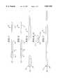
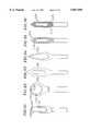
- FIG. 1is a top view of a typical cutting device
- FIG. 2is a side view of the cutting device of FIG. 1;
- FIG. 3is a partial detail view of the cutting device of FIG. 1 illustrating the cutting head, including the angled blade configuration and the entry tip;
- FIG. 4is a cross-sectional view of the cutting head taken along line 4--4 of FIG. 3;
- FIG. 5is a top view of a cutting device having an arrow style entry tip configuration
- FIG. 6is an end view of the cutting device of FIG. 5;
- FIG. 7is a side view of the cutting device of FIG. 5;
- FIG. 8is a top view of a cutting device having a bullet style entry tip configuration
- FIG. 9is an end view of the cutting device of FIG. 8;
- FIG. 10is a side view of the cutting device of FIG. 8;
- FIG. 11is a top view of a cutting device having a elliptical style entry tip configuration
- FIG. 12is an end view of the cutting device of FIG. 11;
- FIG. 13is a side view of the cutting device of FIG. 11;
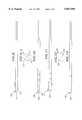
- FIG. 14is a top view of the cutting device of FIG. 1 illustrating the approximate length of the device for use in a non-cannulated open back surgical procedure;
- FIG. 15is a top view of the cutting device of FIG. 1 illustrating the relational length of the device for use in a cannulated endoscopic surgical procedure;
- FIG. 16is a top view of a alternative embodiment cutting device having a rounded style entry tip configuration
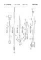
- FIG. 17ais a side view of a drill guard for use in an open back surgical procedure
- FIG. 17bis a side view of a drill guard for use in an endoscopic surgical procedure
- FIG. 18is a side view of a self-aspirating embodiment of the cutting device of FIG. 1;
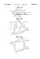
- FIG. 19ais a top view of a round cutting head configuration of the cutting device
- FIG. 19bis a top view of a bulb cutting head configuration of the cutting device.
- FIG. 20is an end view of the cutting head of FIG. 19b having a rounded style entry tip configuration
- FIG. 21ais a top view of a cervical version of the cutting device
- FIG. 21bis a side view of the cutting device of FIG. 21a;
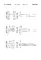
- FIG. 22is a top view of a cutting device illustrating an alternate tapered shaft configuration
- FIG. 23is a side view of the cutting device of FIG. 22 including a bearing or bushing;
- FIG. 24is a side view of a cutting device including multiple bearings and a mechanical depth stop
- FIG. 25is a side view of a cutting device including a full length bearing or bushing
- FIG. 26is a cross-sectional side view of a cutting device captive within a cannula
- FIG. 27is a cutting device with a screw shaft
- FIG. 28is a cross-sectional side view of a modified arrow tip cutting head configuration taken along line 28--28 of FIG. 28A;
- FIG. 28Ais an end view of the cutting head of FIG. 28;
- FIG. 29is a top view of an auger tip cutting head configuration of the cutting device.
- FIG. 29Ais an end view of the cutting head of FIG. 29;
- FIG. 30is a top view of an additional modified arrow tip cutting head configuration
- FIG. 30Ais an end view of the cutting head configuration of FIG. 30;
- FIG. 31is a top view of a modified elliptical cutting head configuration
- FIG. 32is a top view of a modified rounded cutting head configuration
- FIG. 33is a top view of a notch cutting head configuration
- FIG. 34is a top view of a flame cutting head configuration
- FIG. 35is a top view of a fluted cutting head configuration
- FIG. 36is a top view of a rasp cutting head configuration
- FIG. 37is a top view of a cutting head configuration with three cutting blades formed by the window in the cutting head;
- FIG. 38is a cross-sectional end view taken along line 38--38 of FIG. 37;
- FIG. 39is a cross-sectional end view of a cutting head configuration having four cutting blades formed by the window in the cutting head.
- the surgical cutting device 10 of the present inventioncomprises a mounting shaft 12, a main shaft 14 attached to the mounting shaft, and a cutting head 16 positioned at the opposite end of main shaft 14.
- the main shaftcan include optional engraved depth indicators 18 positioned adjacent to the cutting head. Although the cutting device functions properly without the depth indicators, they do add a certain degree of visualization during surgery.
- the cutting head, main shaft, and mounting shaftare an integral piece of hardened surgical steel, wherein the mounting shaft is connected to a rotary drill so that the cutting device can be rotated allowing the cutting head to operate.
- the componentscan be milled from different diameter rod stock and then braised or welded together through a socket or butt joint. Milling from different diameter rod stock is a more efficient use of rod stock which reduces waste and provides an easier milling process for mass production.
- the cutting headincludes a window 20 machined through the cutting head defining two cutting blades 22 on a leading edge of the cutting head as the cutting device is rotated in a counterclockwise direction 24.
- Window 20is machined through the cutting head defining angled walls 26 through the depth of the cutting head. Walls 26 are at an angle ⁇ approximately 15°-30° from a horizontal plane extending perpendicular to the opening of the window.
- the cutting bladescan be smooth as shown in FIG. 3 or serrated.
- Window 20provides an area for removed tissue to accumulate and be further reduced in density, due to the rotation of the cutting blades.
- the removed materialis essentially liquefied and removed by aspiration.
- FIGS. 1-4For a cutting device rotatable in a clockwise direction, the configuration of the cutting blades and tapered walls would be a mirror image of that depicted in FIG. 4.
- the window 20 as shown in FIGS. 1-4is elliptical or oval in shape, however, other shaped windows are contemplated as discussed subsequently herein. It is to be understood that all cutting head versions disclosed herein include a window defining at least two cutting blades as shown in FIGS. 3 and 4.
- FIGS. 5-7illustrate an arrow style entry tip 30 for the cutting device 10.
- the arrow style entry tiphas an elliptical perimeter 32 with a converging sloping surface 34 which converges in a rounded point 36.
- FIGS. 8-10illustrate an alternative entry tip configuration being a bullet style entry tip 38.
- the bullet style entry tipincludes a circular outer perimeter 40 having a sloping converging surface 42 terminating in a rounded point 44.
- FIGS. 11-13illustrate a second alternative entry tip configuration being an elliptical style entry tip 46.
- Elliptical style entry tip 46includes an elliptical perimeter 48 with an arcuate rounded outer surface 50.
- the cutting device of the present inventionhas dimensions that are practical for entry into the spinal intervertebral disk space for the various regions of the spine.
- the typical outside diameter or width of the cutting headwill range from about 3 to about 13 millimeters. Widths of the cutting head can also range from about 5 to about 9 millimeters.
- the cutting headis balanced around the axis of the device so that the device will not wobble during rotation.
- the typical length of the cutting device 10 of the present invention for use in a non-cannulated fashionis from about 3 inches to about 6 inches. This length provides the necessary shaft length for insertion into a surgical drill and drill guard.
- the mounting shaft 12 of the cutting devicehas a reduced diameter from the main shaft 14 for insertion into the surgical drill collet 52.
- FIG. 15illustrates the typical length of the cutting device for use in a cannulated, endoscopic fashion and is from about 8 inches to about 12 inches.
- This lengthprovides the necessary main shaft 14 length for insertion into the surgical drill, a standard surgical cannula and an elongated guard (see FIG. 26) and provides the necessary extension of the entry tip 28 from the cannula for entry into the intervertebral disk.
- the outside diameter of the cannulated endoscopic deviceis that necessary to fit in close tolerance with the inside diameter of a standard guard or surgical cannula.
- the length of all embodiments of the cutting device of the present inventiontypically could increase in increments of 1/2 inch.
- the mounting shaft diameter 12typically would be 0.092 inches or 0.125 inches based upon currently available surgical drill mounting collets 52.
- FIGS. 17a and 17billustrate standard surgical drill guards, wherein FIG. 17a depicts an open back surgery drill guard 54 and FIG. 17b depicts an endoscopic surgery drill guard 56.
- the difference between drill guards 54 and 56is the overall length of the guard.
- Guards 54 and 56are made of surgical steel tubing that slides onto the collet 52 of the drill and is held in place by friction. More specifically, guards 54 and 56 include a friction sleeve 58 which slides over the drill collet 52.
- Drill guards 54 and 56further include a finger pull 60 for insertion and removal of the drill guard and a guard body 62 extending from the finger pull 60.
- a stabilizer bushing 64is positioned at the end of the guard body 62.
- a shaft opening 66extends along the length of the guard for insertion of the cutting device.
- Vent holes 68are typically located along the length of the guard body 72 at given intervals. Standard commercially available guards or custom made guards that are slightly longer and have a slightly larger internal diameter may be used with the cutting device of the present invention.
- FIG. 18illustrates a self-aspirating cutting device 70 which includes an aspiration channel 72 extending along the length of the mounting shaft 74, main shaft 76 and terminating at window 80 in cutting head 78.
- the aspiration channelterminates in openings 82 and 84, in the window of the cutting head and in the mounting shaft, respectively.
- the aspiration channel of the cutting deviceis for aspiration of the removed material.
- the geometrical shape of the cutting headcan also be varied.
- the cutting head 16 of the cutting device embodiments referenced hereinillustrate a generally elliptical cutting head.
- Alternative cutting head geometriescan be seen in FIGS. 16, 19A and 19B.
- FIG. 16illustrates a tear drop cutting head configuration 86 having a rounded entry tip 88 and includes converging walls 90 extending from entry tip 88 to main shaft 92.
- the cutting headincludes a tear drop shaped window 94.
- FIG. 19aillustrates a round cutting head configuration 96.
- the cutting headincludes a rounded outer wall 98 extending from the main shaft 100.
- the round cutting headalso includes a circular window 102.
- FIG. 19billustrates a bulb cutting head configuration 104 having a rounded entry tip 106 and generally parallel side walls 108. Converging back walls 110 extend from the main shaft 112 to the parallel side walls 108.
- the bulb cutting head configurationincludes a generally elliptical or oval window 114.
- the entry tipsIn each of the tear drop cutting head configuration, round head configuration, and bulb head configuration, the entry tips have a rounded configuration as shown in FIG. 20.
- the rounded entry tipincludes an oval perimeter 116 and a rounded outer surface 118.
- FIGS. 21A and 21Billustrate a cervical cutting device 120 wherein the mounting shaft 122 and main shaft 124 are of equal diameter.
- the cervical cutting toolpreferably would have an overall length of 3.75 inches and a cutting head diameter of 0.125 to 0.160 inches. As seen in FIG. 21B, the height of the cutting head 126 is equal to the diameter of the main shaft.
- FIGS. 22 and 23illustrates yet another alternative cutting device 128 having a tapered main shaft 130 without fillets at the juncture between the main shaft and the mounting shaft 132.
- a bushing or bearing 134is placed along the main shaft 130 to reduce the friction between the main shaft and the cannula into which the cutting device is inserted. If a bushing is used, it is preferably made from metal or plastic. If a bearing were used, it would be a ball or race type bearing. Multiple bearings or bushings 134 and 136 can be utilized along the main shaft 138 of a cutting device 140 as shown in FIG. 24. Although two bearings or bushings 134 and 136 are shown, it is to be understood that any multiple number of bearings or bushings having varying lengths can be positioned along the main shaft of the cutting device to reduce friction between the cutting device and a cannula.
- a mechanical depth stop 142can be incorporated into the cutting device typically at the juncture between the main shaft 138 and the mounting shaft 144 to prevent the cutting device from extending too far from the end of the cannula (see FIG. 26) when in use.
- a full length bushing or bearing 146can be positioned on the main shaft 148 of a cutting device 150 as shown in FIG. 25.
- the cutting device 150can be removable from the cannula 152 or can be captive within the cannula as shown in FIG. 26.
- the cannula 152(or a surgical guard in other applications) includes retainer rings 154 and 156 at opposite ends of the main shaft 158 to rigidly secure the cannula to the main shaft.
- Two bearings or bushings 160are positioned within the cannula, however it is to be understood that the number and length of each bearing or bushing can vary for the particular application.
- FIG. 27illustrates an alternative embodiment main shaft configuration for a cutting device 162.
- the main shaft 164is threaded 166, which assists in moving displaced emulsified disk material from the cutting head, up the main shaft 164 and away from the surgical site.
- cutting device 162is only shown in FIG. 27, it is to be understood that device 162 is used in conjunction with a cannula or drill guard as shown in FIG. 26 for device 150.
- the threads 166move the removed tissue along the shaft 164 within the cannula or drill guard.
- FIGS. 28 through 36illustrate additional cutting head configurations for the cutting device.
- FIG. 28illustrates a modified arrow tip cutting head configuration wherein semi-circular portions 170 are removed from the entry tip, thereby defining semi-circular cutting blades 174 positioned on either side of the entry tip 172. Cutting blades 174 on the entry tip provide a smoother entry into the intervertable disk space and a more rapid removal of matter.
- FIGS. 29 and 29Aillustrate an auger tip cutting head configuration wherein the entry tip includes a narrow pyramidal entry portion 176 and angled base portions 178 and 180. A blade 182 is machined onto the leading edge of the pyramidal center portion 176. Blade 182 also provides a smoother entry into the intervertebral disk space and rapid removal of matter.
- FIG. 28illustrates a modified arrow tip cutting head configuration wherein semi-circular portions 170 are removed from the entry tip, thereby defining semi-circular cutting blades 174 positioned on either side of the entry tip 172. Cutting blades 174
- FIG. 30illustrates a second modified arrow tip configuration in which a semi-circular and angled portion 184 is removed from each end of the entry tip to form a cutting blade 186 having a semi-circular portion 188 and an angled relief portion 190.
- Semi-circular and angled portion 184provide a more aggressive cutting action for the cutting device.
- FIGS. 31 and 32illustrate modified elliptical and round cutting head configurations, respectively wherein the window 192 has been raised so that the window 192 forms a thin portion 194 along the upper perimeter of the entry tip thereby extending the cutting blade around the upper perimeter 196 in the window.
- the cutting bladeis not limited to just the sides of the window and allows for the easy removal of disk material using a lateral movement of the cutting device across the intervertebral disk space.
- FIG. 33illustrates a notched cutting head configuration wherein each side of the cutting head includes serrations 198.
- FIG. 34illustrates a flame shaped cutting head configuration 200.
- FIG. 35illustrates a fluted cutting head configuration 202 wherein the cutting head includes raised spiral flutes or helixes 204 circling the diameter of the head.
- FIG. 36illustrates a rasp cutting head configuration 206 wherein the cutting head is knurled producing smaller flutes 208 and 210 criss-crossing in both directions around the diameter of the cutting head.
- the cutting head configurations of FIGS. 33 through 36allow for the easy removal of matter using a lateral movement of the cutting head across the intervertebral disk space, and in particular the flutes of FIGS. 35 and 36 provide for the head to be more aggressive in the removal of material. Additionally, any of the cutting head configurations depicted herein can be diamond coated by dipping the cutting heads into a diamond emulsion to enhance the cutting capabilities of the device.
- the cutting device of the present inventioncan also be designed to include three or more cutting blades on leading edges of a window in the cutting head. As seen in FIGS. 37-39, three and four cutting blades are shown. A device with additional cutting blades can be used where additional cutting action is desired. However, adding cutting blades does involve more complex configurations that can be more difficult and expensive to manufacture.
- the cutting device 212 of FIGS. 37 and 38illustrate a three bladed configuration wherein the cutting head 214 includes a window 216 machined through the cutting device defining three cutting blades 218A, 218B, 218C on a leading edge of the cutting head as the cutting device is rotated in a counterclockwise direction 220.
- Window 216is preferably formed using an EDM wire (electrical discharge machine) to electrically remove material to form the window and blades. Other standard machining processes can also be used such as, for example, milling.
- Window 216is machined to define angled walls 222 and a relief portion 224.
- FIG. 39illustrates a cutting device 226 having four cutting blades 228A, 228B, 228C and 228D spaced around the circumference of a window 230 of the cutting head 232.
- Cutting device 226is similar to device 212 except the cutting blades are slightly smaller to accommodate the additional blade.
- all of the cutting bladesare of equal size and uniformly spaced around the circumference of the cutting head, however, it is contemplated that the cutting blades could be of different sizes and nonuniformly spaced around the circumference of the cutting head but only in configurations where the combination of size and position ensures that the cutting device does not wobble during rotation.
- the inventionalso contemplates versions having more than four cutting blades spaced around a window of the cutting head.
- All of the cutting devices with three or more blades on leading edges of a windowcan include any of the features discussed above with respect to a two-bladed version, such as, for example, shaft styles, head and entry tip shapes, use with cannulas or guards, and can be formed from a single piece of surgical steel or multiple pieces joined together.
Landscapes
- Health & Medical Sciences (AREA)
- Surgery (AREA)
- Life Sciences & Earth Sciences (AREA)
- Biomedical Technology (AREA)
- Medical Informatics (AREA)
- Orthopedic Medicine & Surgery (AREA)
- Veterinary Medicine (AREA)
- Engineering & Computer Science (AREA)
- Public Health (AREA)
- Heart & Thoracic Surgery (AREA)
- Nuclear Medicine, Radiotherapy & Molecular Imaging (AREA)
- Molecular Biology (AREA)
- Animal Behavior & Ethology (AREA)
- General Health & Medical Sciences (AREA)
- Dentistry (AREA)
- Oral & Maxillofacial Surgery (AREA)
- Surgical Instruments (AREA)
Abstract
Description
Claims (24)
Priority Applications (6)
| Application Number | Priority Date | Filing Date | Title |
|---|---|---|---|
| US08/889,016US5857995A (en) | 1996-08-15 | 1997-07-07 | Multiple bladed surgical cutting device removably connected to a rotary drive element |
| CA002288768ACA2288768C (en) | 1997-05-08 | 1998-05-07 | Multiple bladed surgical cutting device removably connected to a rotary drive element |
| PCT/US1998/009414WO1998049945A1 (en) | 1997-05-08 | 1998-05-07 | Multiple bladed surgical cutting device removably connected to a rotary drive element |
| JP54852998AJP2001526565A (en) | 1997-05-08 | 1998-05-07 | Multi-blade surgical cutting instrument detachably connected to a rotary drive element |
| EP98920348AEP0986328A4 (en) | 1997-05-08 | 1998-05-07 | Multiple bladed surgical cutting device removably connected to a rotary drive element |
| AU72946/98AAU726056C (en) | 1997-05-08 | 1998-05-07 | Multiple bladed surgical cutting device removably connected to a rotary drive element |
Applications Claiming Priority (3)
| Application Number | Priority Date | Filing Date | Title |
|---|---|---|---|
| US69598496A | 1996-08-15 | 1996-08-15 | |
| US08/853,065US5925056A (en) | 1996-04-12 | 1997-05-08 | Surgical cutting device removably connected to a rotary drive element |
| US08/889,016US5857995A (en) | 1996-08-15 | 1997-07-07 | Multiple bladed surgical cutting device removably connected to a rotary drive element |
Related Parent Applications (1)
| Application Number | Title | Priority Date | Filing Date |
|---|---|---|---|
| US08/853,065Continuation-In-PartUS5925056A (en) | 1996-04-12 | 1997-05-08 | Surgical cutting device removably connected to a rotary drive element |
Publications (1)
| Publication Number | Publication Date |
|---|---|
| US5857995Atrue US5857995A (en) | 1999-01-12 |
Family
ID=27127112
Family Applications (1)
| Application Number | Title | Priority Date | Filing Date |
|---|---|---|---|
| US08/889,016Expired - LifetimeUS5857995A (en) | 1996-08-15 | 1997-07-07 | Multiple bladed surgical cutting device removably connected to a rotary drive element |
Country Status (5)
| Country | Link |
|---|---|
| US (1) | US5857995A (en) |
| EP (1) | EP0986328A4 (en) |
| JP (1) | JP2001526565A (en) |
| CA (1) | CA2288768C (en) |
| WO (1) | WO1998049945A1 (en) |
Cited By (176)
| Publication number | Priority date | Publication date | Assignee | Title |
|---|---|---|---|---|
| US6174311B1 (en) | 1998-10-28 | 2001-01-16 | Sdgi Holdings, Inc. | Interbody fusion grafts and instrumentation |
| USRE37304E1 (en)* | 1996-11-15 | 2001-07-31 | Rhein Medical, Inc. | Surgical knife blade |
| US20020165550A1 (en)* | 1999-10-21 | 2002-11-07 | George Frey | Devices and techniques for a posterior lateral disc space approach |
| US20030018347A1 (en)* | 2001-07-23 | 2003-01-23 | Ioannis Pallikaris | Device for separating the epithelium layer from the surface of the cornea of an eye |
| US20030023306A1 (en)* | 2000-03-14 | 2003-01-30 | Mingyan Liu | Vertebral implant for promoting arthrodesis of the spine |
| US20030078589A1 (en)* | 1998-04-01 | 2003-04-24 | Preissman Howard E. | High pressure applicator |
| US6579298B1 (en)* | 2000-02-29 | 2003-06-17 | Scimed Life Systems, Inc. | Method and apparatus for treating vein graft lesions |
| US20030144678A1 (en)* | 1996-02-07 | 2003-07-31 | Hellenkamp Johann F. | Automatic surgical device and control assembly for cutting a cornea |
| US6610089B1 (en) | 1997-08-26 | 2003-08-26 | Sdgi Holdings, Inc. | Spinal implant and cutting tool preparation accessory for mounting the implant |
| US20040010231A1 (en)* | 2000-07-13 | 2004-01-15 | Leonhardt Howard J | Deployment system for myocardial cellular material |
| US20040030346A1 (en)* | 1999-10-21 | 2004-02-12 | George Frey | Devices and techniques for a posterior lateral disc space approach |
| US20040059254A1 (en)* | 2001-03-23 | 2004-03-25 | Stryker Puerto Rico Limited | Micro-invasive breast biopsy device |
| US20040073139A1 (en)* | 2002-10-11 | 2004-04-15 | Hirsch Joshua A. | Cannula for extracting and implanting material |
| US20040073309A1 (en)* | 1997-06-03 | 2004-04-15 | Bianchi John R. | Open intervertebral spacer |
| US20040088053A1 (en)* | 2002-10-30 | 2004-05-06 | Hassan Serhan | Regenerative implants for stabilizing the spine and devices for attachment of said implants |
| US20040092980A1 (en)* | 2001-10-26 | 2004-05-13 | Cesarini Peter M. | Reciprocating rotary arthroscopic surgical instrument |
| US20040102784A1 (en)* | 2000-07-12 | 2004-05-27 | Denis Pasquet | Curettage instrument |
| US6764491B2 (en) | 1999-10-21 | 2004-07-20 | Sdgi Holdings, Inc. | Devices and techniques for a posterior lateral disc space approach |
| US20040181250A1 (en)* | 2003-02-20 | 2004-09-16 | Adams Kenneth M | Surgical elongate blade assembly with interchangeable inner member, kit and method relating thereto |
| US20040220599A1 (en)* | 2001-07-23 | 2004-11-04 | Fos Holding S.A. | Device for separating the epithelium layer from the surface of the cornea of an eye |
| US20040236358A1 (en)* | 2003-04-07 | 2004-11-25 | Barrile-Josephson Craig A. | Bar-link drive system for a microkeratome |
| US20040260321A1 (en)* | 2002-12-19 | 2004-12-23 | Ming-Kok Tai | Apparatus and method for separating the epithelium layer from the cornea of an eye without corneal pre-applanation |
| US20040260320A1 (en)* | 2002-12-10 | 2004-12-23 | Lisk James R. | Disposable separator for separating the epithelium layer from the cornea of an eye |
| US20050055041A1 (en)* | 2003-09-05 | 2005-03-10 | Sightrate B.V. | Device for separation of corneal epithelium |
| US20050070907A1 (en)* | 2003-09-25 | 2005-03-31 | Abernathie Dennis L. | Method and device for drilling and tapping a bore for a bone screw |
| US20050197661A1 (en)* | 2004-03-03 | 2005-09-08 | Scimed Life Systems, Inc. | Tissue removal probe with sliding burr in cutting window |
| US20050203527A1 (en)* | 2004-03-03 | 2005-09-15 | Scimed Life Systems, Inc. | Apparatus and methods for removing vertebral bone and disc tissue |
| US20050209610A1 (en)* | 2004-03-03 | 2005-09-22 | Scimed Life Systems, Inc. | Radially adjustable tissue removal device |
| US20050209622A1 (en)* | 2004-03-03 | 2005-09-22 | Scimed Life Systems, Inc. | Tissue removal probe with irrigation and aspiration ports |
| US20050209530A1 (en)* | 2001-03-23 | 2005-09-22 | Stryker Puerto Rico Limited | Micro-invasive tissue removal device |
| US20050228398A1 (en)* | 2004-04-12 | 2005-10-13 | Rathbun David S | Free hand drill guide |
| US20060064101A1 (en)* | 2004-02-12 | 2006-03-23 | Arthrocare Corporation | Bone access system |
| US20060161176A1 (en)* | 2004-01-12 | 2006-07-20 | Heegaard Eric G | Medical device for perforating a biological membrane |
| US20060164913A1 (en)* | 2005-01-21 | 2006-07-27 | Arthrocare Corporation | Multi-chamber integrated mixing and delivery system |
| US20060185490A1 (en)* | 2005-02-23 | 2006-08-24 | Mincer Mathew T | Microtome blade |
| US20060282011A1 (en)* | 2005-06-08 | 2006-12-14 | Vogeler Douglas M | Elliptical biopsy guide |
| US20070055259A1 (en)* | 2005-08-17 | 2007-03-08 | Norton Britt K | Apparatus and methods for removal of intervertebral disc tissues |
| US7226459B2 (en) | 2001-10-26 | 2007-06-05 | Smith & Nephew, Inc. | Reciprocating rotary arthroscopic surgical instrument |
| US20070161962A1 (en)* | 2006-01-09 | 2007-07-12 | Edie Jason A | Device and method for moving fill material to an implant |
| US20070162062A1 (en)* | 2005-12-08 | 2007-07-12 | Norton Britt K | Reciprocating apparatus and methods for removal of intervertebral disc tissues |
| US20070162129A1 (en)* | 2006-01-09 | 2007-07-12 | Edie Jason A | Adjustable insertion device for a vertebral implant |
| US20070244496A1 (en)* | 1996-02-07 | 2007-10-18 | Hellenkamp Johann F | Automatic surgical device and control assembly for cutting a cornea |
| US20070255172A1 (en)* | 2001-03-23 | 2007-11-01 | Stryker Puerto Rico Limited | Micro-invasive nucleotomy device and method |
| US20070265650A1 (en)* | 2001-07-23 | 2007-11-15 | Ioannis Pallikaris | Device for separating the epithelial layer from the surface of the cornea of an eye |
| US20070293949A1 (en)* | 2004-10-08 | 2007-12-20 | Salerni Anthony A | Interior connecting interbody cage insertional tools, methods and devices |
| US20080021488A1 (en)* | 2006-07-24 | 2008-01-24 | Sascha Berberich | Medical Instrument for Cutting Tissue |
| US7344539B2 (en) | 2001-03-30 | 2008-03-18 | Depuy Acromed, Inc. | Intervertebral connection system |
| US20080154304A1 (en)* | 2006-12-21 | 2008-06-26 | Arthrocare Corporation | System and method for accessing a tissue structure |
| US20080243122A1 (en)* | 2007-03-29 | 2008-10-02 | Kohm Andrew C | Apparatuses and methods for bone screw augmentation |
| US20080269754A1 (en)* | 2007-03-06 | 2008-10-30 | Orthobond, Inc. | Preparation Tools and Methods of Using the Same |
| US7468048B2 (en) | 2006-10-06 | 2008-12-23 | National Jewish Health | Joint aspirate facilitating device |
| US7485125B2 (en)* | 2001-12-17 | 2009-02-03 | Smith & Nephew, Inc. | Cutting instrument |
| US20100023065A1 (en)* | 2008-07-25 | 2010-01-28 | Welch Andrea M | Tissue access device with alignment guide and methods of use |
| US20100043612A1 (en)* | 2007-04-20 | 2010-02-25 | Feather Safety Razor Co., Ltd. | Replaceable blade for microtome and curl prevention plate |
| US20100137835A1 (en)* | 2003-07-15 | 2010-06-03 | Leonhardt Howard J | Deployment system for myocardial cellular material |
| US20100234849A1 (en)* | 2004-11-19 | 2010-09-16 | Conformis, Inc. | Surgical Cutting Tool |
| US7905886B1 (en)* | 2003-07-07 | 2011-03-15 | Nuvasive Inc. | System and methods for performing transforaminal lumbar interbody fusion |
| US7935122B2 (en) | 2004-12-23 | 2011-05-03 | Arthrocare Corporation | Cannula having asymmetrically-shaped threads |
| USRE42959E1 (en) | 1996-12-02 | 2011-11-22 | Abbott Cardiovascular Systems Inc. | Apparatus and methods for stimulating revascularization and/or tissue growth |
| US8123756B2 (en) | 1999-09-30 | 2012-02-28 | Neurotherm, Inc. | High pressure delivery system |
| USRE43300E1 (en) | 1996-12-02 | 2012-04-03 | Abbott Cardiovascular Systems Inc. | Apparatus having stabilization members for percutaneously performing surgery and methods of use |
| WO2013007116A1 (en)* | 2011-07-13 | 2013-01-17 | 北京水木天蓬医疗技术有限公司 | Ultrasonic osteotome head |
| US8623088B1 (en) | 2005-07-15 | 2014-01-07 | Nuvasive, Inc. | Spinal fusion implant and related methods |
| US8845733B2 (en) | 2010-06-24 | 2014-09-30 | DePuy Synthes Products, LLC | Lateral spondylolisthesis reduction cage |
| US8893722B2 (en) | 1997-09-04 | 2014-11-25 | Smith & Nephew, Inc. | Surgical endoscopic cutting device and method for its use |
| USD731063S1 (en) | 2009-10-13 | 2015-06-02 | Nuvasive, Inc. | Spinal fusion implant |
| USRE45638E1 (en) | 1996-12-02 | 2015-08-04 | Abbott Cardiovascular Systems Inc. | Apparatus for percutaneously performing myocardial revascularization having means for sensing tissue parameters and method of use |
| US9125550B2 (en) | 2004-08-27 | 2015-09-08 | Smith & Nephew, Inc. | Tissue resecting system |
| US9155454B2 (en) | 2010-09-28 | 2015-10-13 | Smith & Nephew, Inc. | Hysteroscopic system |
| USD741488S1 (en) | 2006-07-17 | 2015-10-20 | Nuvasive, Inc. | Spinal fusion implant |
| US9226764B2 (en) | 2012-03-06 | 2016-01-05 | DePuy Synthes Products, Inc. | Conformable soft tissue removal instruments |
| US20160066929A1 (en)* | 2014-09-09 | 2016-03-10 | Russo Surgical Tools, LLC | Surgical instrument for harvesting bone |
| US9332995B2 (en) | 2012-09-25 | 2016-05-10 | Russo Inventions, Llc | Bone-harvesting tool |
| US9364260B2 (en) | 2012-05-25 | 2016-06-14 | Depuy Mitek, Llc | Method for atraumatic hip access |
| US9585675B1 (en)* | 2015-10-23 | 2017-03-07 | RELIGN Corporation | Arthroscopic devices and methods |
| CN107073601A (en)* | 2014-08-14 | 2017-08-18 | 史赛克欧洲控股I有限责任公司 | Surgical drill with single cutting chip area |
| US9855675B1 (en)* | 2016-09-20 | 2018-01-02 | RELIGN Corporation | Arthroscopic devices and methods |
| US20180078279A1 (en)* | 2016-09-20 | 2018-03-22 | RELIGN Corporation | Arthroscopic devices and methods |
| US9931224B2 (en) | 2009-11-05 | 2018-04-03 | DePuy Synthes Products, Inc. | Self-pivoting spinal implant and associated instrumentation |
| WO2018059261A1 (en)* | 2016-09-28 | 2018-04-05 | 江苏水木天蓬科技有限公司 | Ultrasonic osteotome cutter bit |
| US10022140B2 (en) | 2016-02-04 | 2018-07-17 | RELIGN Corporation | Arthroscopic devices and methods |
| US10022245B2 (en) | 2012-12-17 | 2018-07-17 | DePuy Synthes Products, Inc. | Polyaxial articulating instrument |
| US20180263649A1 (en)* | 2017-03-17 | 2018-09-20 | RELIGN Corporation | Arthroscopic devices and methods |
| US10172644B2 (en) | 2006-03-29 | 2019-01-08 | Edge Systems Llc | Devices, systems and methods for treating the skin |
| US10179229B2 (en) | 2014-12-23 | 2019-01-15 | Edge Systems Llc | Devices and methods for treating the skin using a porous member |
| US10238812B2 (en) | 2013-03-15 | 2019-03-26 | Edge Systems Llc | Skin treatment systems and methods using needles |
| US10251675B2 (en) | 2006-03-29 | 2019-04-09 | Edge Systems Llc | Devices, systems and methods for treating the skin |
| US10299819B2 (en) | 2016-07-28 | 2019-05-28 | Covidien Lp | Reciprocating rotary surgical cutting device and system for tissue resecting, and method for its use |
| US10299803B2 (en) | 2016-08-04 | 2019-05-28 | Covidien Lp | Self-aligning drive coupler |
| US10357642B2 (en) | 2005-12-30 | 2019-07-23 | Edge Systems Llc | Removable tips for use with skin treatment systems |
| US10368881B2 (en) | 2016-06-03 | 2019-08-06 | Quandary Medical, Llc | Method and apparatus for minimally invasive posterolateral spinal fusion |
| US10517609B1 (en)* | 2014-09-10 | 2019-12-31 | Andrew S. Kaplan | Suture drill apparatus and method |
| US10556097B2 (en) | 2008-01-29 | 2020-02-11 | Edge Systems Llc | Devices for treating skin using treatment materials located along a tip |
| US10556096B2 (en) | 2008-01-04 | 2020-02-11 | Edge Systems Llc | Devices and methods for skin treatment |
| US10582966B2 (en) | 2015-04-21 | 2020-03-10 | RELIGN Corporation | Arthroscopic devices and methods |
| US10595889B2 (en) | 2016-04-11 | 2020-03-24 | RELIGN Corporation | Arthroscopic devices and methods |
| US20200113619A1 (en)* | 2018-10-11 | 2020-04-16 | Rebound Therapeutics Corporation | Cautery tool for intracranial surgery |
| US10631889B2 (en) | 2014-12-16 | 2020-04-28 | Covidien Lp | Surgical device with incorporated tissue extraction |
| US10750931B2 (en) | 2015-05-26 | 2020-08-25 | Covidien Lp | Systems and methods for generating a fluid bearing for an operative procedure |
| US10772652B2 (en) | 2015-01-28 | 2020-09-15 | Covidien Lp | Tissue resection system |
| US10772654B2 (en) | 2017-03-02 | 2020-09-15 | Covidien Lp | Fluid-driven tissue resecting instruments, systems, and methods |
| US10799264B2 (en) | 2015-06-18 | 2020-10-13 | Covidien Lp | Surgical instrument with suction control |
| US10804769B2 (en) | 2015-06-17 | 2020-10-13 | Covidien Lp | Surgical instrument with phase change cooling |
| US10842350B2 (en) | 2015-06-17 | 2020-11-24 | Covidien Lp | Endoscopic device with drip flange and methods of use thereof for an operative procedure |
| US10869684B2 (en) | 2018-02-13 | 2020-12-22 | Covidien Lp | Powered tissue resecting device |
| US10898218B2 (en) | 2019-02-25 | 2021-01-26 | Covidien Lp | Tissue resecting device including a motor cooling assembly |
| US10945752B2 (en) | 2019-03-20 | 2021-03-16 | Covidien Lp | Tissue resecting instrument including a rotation lock feature |
| US20210093371A1 (en)* | 2019-09-30 | 2021-04-01 | RELIGN Corporation | Medical devices and method |
| US10966843B2 (en) | 2017-07-18 | 2021-04-06 | DePuy Synthes Products, Inc. | Implant inserters and related methods |
| US10993743B2 (en) | 2013-03-15 | 2021-05-04 | Edge Systems Llc | Devices, systems and methods for treating the skin |
| DE102019130568A1 (en)* | 2019-11-13 | 2021-05-20 | Aesculap Ag | Surgical cutter with improved chip evacuation |
| US11020577B2 (en) | 2008-01-29 | 2021-06-01 | Edge Systems Llc | Devices and systems for treating skin surfaces |
| US11045287B2 (en)* | 2016-01-29 | 2021-06-29 | Nobel Biocare Services Ag | Dentistry tool |
| US11045331B2 (en) | 2017-08-14 | 2021-06-29 | DePuy Synthes Products, Inc. | Intervertebral implant inserters and related methods |
| US11065147B2 (en) | 2018-10-18 | 2021-07-20 | Covidien Lp | Devices, systems, and methods for pre-heating fluid to be introduced into a patient during a surgical procedure |
| US11083481B2 (en) | 2019-02-22 | 2021-08-10 | Covidien Lp | Tissue resecting instrument including an outflow control seal |
| US11154318B2 (en) | 2019-02-22 | 2021-10-26 | Covidien Lp | Tissue resecting instrument including an outflow control seal |
| US11172953B2 (en) | 2016-04-11 | 2021-11-16 | RELIGN Corporation | Arthroscopic devices and methods |
| US11179172B2 (en) | 2019-12-05 | 2021-11-23 | Covidien Lp | Tissue resecting instrument |
| US11197710B2 (en) | 2018-10-26 | 2021-12-14 | Covidien Lp | Tissue resecting device including a blade lock and release mechanism |
| US11207119B2 (en) | 2016-03-11 | 2021-12-28 | RELIGN Corporation | Arthroscopic devices and methods |
| US11234759B2 (en) | 2015-10-23 | 2022-02-01 | RELIGN Corporation | Arthroscopic devices and methods |
| US11241357B2 (en) | 2015-07-08 | 2022-02-08 | Edge Systems Llc | Devices, systems and methods for promoting hair growth |
| US11317947B2 (en) | 2020-02-18 | 2022-05-03 | Covidien Lp | Tissue resecting instrument |
| US11344424B2 (en) | 2017-06-14 | 2022-05-31 | Medos International Sarl | Expandable intervertebral implant and related methods |
| US11369490B2 (en) | 2011-03-22 | 2022-06-28 | DePuy Synthes Products, Inc. | Universal trial for lateral cages |
| US11376032B2 (en) | 2019-12-05 | 2022-07-05 | Covidien Lp | Tissue resecting instrument |
| US11426290B2 (en) | 2015-03-06 | 2022-08-30 | DePuy Synthes Products, Inc. | Expandable intervertebral implant, system, kit and method |
| US11426231B2 (en) | 2017-01-11 | 2022-08-30 | RELIGN Corporation | Arthroscopic devices and methods |
| US11432942B2 (en) | 2006-12-07 | 2022-09-06 | DePuy Synthes Products, Inc. | Intervertebral implant |
| US11446156B2 (en) | 2018-10-25 | 2022-09-20 | Medos International Sarl | Expandable intervertebral implant, inserter instrument, and related methods |
| US11446155B2 (en) | 2017-05-08 | 2022-09-20 | Medos International Sarl | Expandable cage |
| US11452806B2 (en) | 2019-10-04 | 2022-09-27 | Covidien Lp | Outflow collection vessels, systems, and components thereof for hysteroscopic surgical procedures |
| US11452607B2 (en) | 2010-10-11 | 2022-09-27 | DePuy Synthes Products, Inc. | Expandable interspinous process spacer implant |
| US11497619B2 (en) | 2013-03-07 | 2022-11-15 | DePuy Synthes Products, Inc. | Intervertebral implant |
| US11510788B2 (en) | 2016-06-28 | 2022-11-29 | Eit Emerging Implant Technologies Gmbh | Expandable, angularly adjustable intervertebral cages |
| USD974558S1 (en) | 2020-12-18 | 2023-01-03 | Stryker European Operations Limited | Ultrasonic knife |
| US11547782B2 (en) | 2020-01-31 | 2023-01-10 | Covidien Lp | Fluid collecting sheaths for endoscopic devices and systems |
| US11547815B2 (en) | 2018-05-30 | 2023-01-10 | Covidien Lp | Systems and methods for measuring and controlling pressure within an internal body cavity |
| US11553977B2 (en) | 2019-05-29 | 2023-01-17 | Covidien Lp | Hysteroscopy systems and methods for managing patient fluid |
| US11571233B2 (en) | 2020-11-19 | 2023-02-07 | Covidien Lp | Tissue removal handpiece with integrated suction |
| US11596522B2 (en) | 2016-06-28 | 2023-03-07 | Eit Emerging Implant Technologies Gmbh | Expandable and angularly adjustable intervertebral cages with articulating joint |
| US11596429B2 (en) | 2020-04-20 | 2023-03-07 | Covidien Lp | Tissue resecting instrument |
| US11602438B2 (en) | 2008-04-05 | 2023-03-14 | DePuy Synthes Products, Inc. | Expandable intervertebral implant |
| US11607321B2 (en) | 2009-12-10 | 2023-03-21 | DePuy Synthes Products, Inc. | Bellows-like expandable interbody fusion cage |
| US11612491B2 (en) | 2009-03-30 | 2023-03-28 | DePuy Synthes Products, Inc. | Zero profile spinal fusion cage |
| US11622868B2 (en) | 2007-06-26 | 2023-04-11 | DePuy Synthes Products, Inc. | Highly lordosed fusion cage |
| US11654033B2 (en) | 2010-06-29 | 2023-05-23 | DePuy Synthes Products, Inc. | Distractible intervertebral implant |
| US11737777B2 (en) | 2020-02-05 | 2023-08-29 | Covidien Lp | Tissue resecting instruments |
| US11737881B2 (en) | 2008-01-17 | 2023-08-29 | DePuy Synthes Products, Inc. | Expandable intervertebral implant and associated method of manufacturing the same |
| WO2023164094A1 (en)* | 2022-02-25 | 2023-08-31 | Life Spine, Inc. | Vertebral disc auger |
| US11744999B2 (en) | 2014-12-23 | 2023-09-05 | Hydra Facial LLC | Devices and methods for treating the skin |
| US11752009B2 (en) | 2021-04-06 | 2023-09-12 | Medos International Sarl | Expandable intervertebral fusion cage |
| US11806245B2 (en) | 2020-03-06 | 2023-11-07 | Eit Emerging Implant Technologies Gmbh | Expandable intervertebral implant |
| WO2023164576A3 (en)* | 2022-02-23 | 2023-11-23 | Treace Medical Concepts, Inc. | Multi-sided cutting instrument for mobilizing small bones in the foot |
| US11850160B2 (en) | 2021-03-26 | 2023-12-26 | Medos International Sarl | Expandable lordotic intervertebral fusion cage |
| US11864735B2 (en) | 2016-05-26 | 2024-01-09 | Covidien Lp | Continuous flow endoscope |
| US11872139B2 (en) | 2010-06-24 | 2024-01-16 | DePuy Synthes Products, Inc. | Enhanced cage insertion assembly |
| US11883058B2 (en) | 2019-03-26 | 2024-01-30 | Covidien Lp | Jaw members, end effector assemblies, and ultrasonic surgical instruments including the same |
| US11890237B2 (en) | 2019-10-04 | 2024-02-06 | Covidien Lp | Outflow collection vessels, systems, and components thereof for hysteroscopic surgical procedures |
| USD1016615S1 (en) | 2021-09-10 | 2024-03-05 | Hydrafacial Llc | Container for a skin treatment device |
| USRE49973E1 (en) | 2013-02-28 | 2024-05-21 | DePuy Synthes Products, Inc. | Expandable intervertebral implant, system, kit and method |
| USD1036670S1 (en)* | 2022-02-21 | 2024-07-23 | Bionix, Llc | Curette tip |
| USD1042807S1 (en) | 2021-10-11 | 2024-09-17 | Hydrafacial Llc | Skin treatment tip |
| US12090064B2 (en) | 2022-03-01 | 2024-09-17 | Medos International Sarl | Stabilization members for expandable intervertebral implants, and related systems and methods |
| US12156673B2 (en) | 2020-10-07 | 2024-12-03 | Covidien Lp | Temperature measurement device for a handpiece of a surgical instrument |
| US12167888B2 (en) | 2016-03-10 | 2024-12-17 | RELIGN Corporation | Arthroscopic devices and methods |
| USD1065551S1 (en) | 2021-09-10 | 2025-03-04 | Hydrafacial Llc | Skin treatment device |
| CN119606490A (en)* | 2024-12-30 | 2025-03-14 | 华中科技大学同济医学院附属同济医院 | A circular internal cutting and closing device for subpleural ground glass nodules of the lung |
| USD1068078S1 (en) | 2023-02-08 | 2025-03-25 | Treace Medical Concepts, Inc. | Handle for an orthopedic instrument |
| USD1068077S1 (en) | 2023-02-08 | 2025-03-25 | Treace Medical Concepts, Inc. | Orthopedic rasp for preparing an intercuneiform joint |
| US12295618B2 (en) | 2020-01-06 | 2025-05-13 | Hydrafacial Llc | Skin treatment tool applicator tip |
| US12303109B2 (en) | 2021-12-22 | 2025-05-20 | Covidien Lp | Surgical systems and methods for component cooling while warming fluid to be introduced during a surgical procedure |
| USD1084369S1 (en) | 2023-02-10 | 2025-07-15 | Hydrafacial Llc | Skin treatment tip |
| US12364500B2 (en) | 2021-05-26 | 2025-07-22 | Covidien Lp | Tissue resecting instrument |
| US12440346B2 (en) | 2023-03-31 | 2025-10-14 | DePuy Synthes Products, Inc. | Expandable intervertebral implant |
Families Citing this family (24)
| Publication number | Priority date | Publication date | Assignee | Title |
|---|---|---|---|---|
| US6083228A (en)* | 1998-06-09 | 2000-07-04 | Michelson; Gary K. | Device and method for preparing a space between adjacent vertebrae to receive an insert |
| EP1681021A3 (en) | 1998-06-09 | 2009-04-15 | Warsaw Orthopedic, Inc. | Abrading element for preparing a space between adjacent vertebral bodies |
| US6692501B2 (en) | 2000-12-14 | 2004-02-17 | Gary K. Michelson | Spinal interspace shaper |
| AU2004283727A1 (en)* | 2003-10-23 | 2005-05-06 | Trans1 Inc. | Tools and tool kits for performing minimally invasive procedures on the spine |
| DE502004010650D1 (en)* | 2003-12-10 | 2010-03-04 | Cervitech Inc | INSTRUMENTARIUM FOR USING AN INTERMEDIATE JOINT PROSTHESIS |
| NZ534215A (en)* | 2004-07-20 | 2005-12-23 | Enztec Ltd | Improved surgical drill |
| FR2883156B1 (en)* | 2005-03-15 | 2008-06-27 | Jean Claude Yeung | DRILL BIT AND RECOVERY OF MULTI-BLADE BONE |
| FR2898484B1 (en)* | 2006-03-16 | 2009-02-27 | Fournitures Hospitalieres Ind | TOOL FOR MAKING A BORING INTO A BONE |
| WO2007104837A1 (en)* | 2006-03-16 | 2007-09-20 | Jean-Claude Yeung | Bone-reaming drill with multiple blades |
| US11202639B2 (en) | 2007-05-02 | 2021-12-21 | Arthrex, Inc. | Combined flip cutter and drill |
| EP2098177B1 (en) | 2008-03-03 | 2013-10-16 | Arthrex, Inc. | Combined flip cutter and drill |
| US9125720B2 (en) | 2008-10-13 | 2015-09-08 | Alcon Research, Ltd. | Capsularhexis device with flexible heating element |
| US8137344B2 (en) | 2008-12-10 | 2012-03-20 | Alcon Research, Ltd. | Flexible, automated capsulorhexis device |
| US8157797B2 (en) | 2009-01-12 | 2012-04-17 | Alcon Research, Ltd. | Capsularhexis device with retractable bipolar electrodes |
| US8814854B2 (en) | 2009-06-03 | 2014-08-26 | Alcon Research, Ltd. | Capsulotomy repair device and method for capsulotomy repair |
| US9241755B2 (en) | 2010-05-11 | 2016-01-26 | Alcon Research, Ltd. | Capsule polishing device and method for capsule polishing |
| US9149388B2 (en) | 2010-09-29 | 2015-10-06 | Alcon Research, Ltd. | Attenuated RF power for automated capsulorhexis |
| CN102475567B (en)* | 2011-05-03 | 2014-07-09 | 江苏水木天蓬科技有限公司 | Ultrasonic bone knife head |
| WO2012149837A1 (en)* | 2011-05-03 | 2012-11-08 | 江苏水木天蓬科技有限公司 | Piezosurgery tool bit |
| DE102011084792A1 (en)* | 2011-10-19 | 2013-04-25 | Söring GmbH | sonotrode |
| USD707818S1 (en) | 2013-03-05 | 2014-06-24 | Alcon Research Ltd. | Capsulorhexis handpiece |
| WO2014159225A2 (en) | 2013-03-14 | 2014-10-02 | Baxano Surgical, Inc. | Spinal implants and implantation system |
| USD737438S1 (en) | 2014-03-04 | 2015-08-25 | Novartis Ag | Capsulorhexis handpiece |
| DE102020133579B3 (en)* | 2020-12-15 | 2022-04-28 | Eberle Gmbh & Co. Kg | Surgical instrument for removing cartilage tissue and/or bone material |
Citations (4)
| Publication number | Priority date | Publication date | Assignee | Title |
|---|---|---|---|---|
| US3996935A (en)* | 1969-02-14 | 1976-12-14 | Surgical Design Corporation | Surgical-type method for removing material |
| US4167943A (en)* | 1977-06-27 | 1979-09-18 | Surgical Design Corp. | Blade type rotatable surgical cutting instrument with improved cutter blade wear |
| US5456689A (en)* | 1993-10-13 | 1995-10-10 | Arnold J. Kresch | Method and device for tissue resection |
| US5492528A (en)* | 1990-07-17 | 1996-02-20 | Anis; Azis Y. | Removal of tissue |
Family Cites Families (8)
| Publication number | Priority date | Publication date | Assignee | Title |
|---|---|---|---|---|
| US5509923A (en)* | 1989-08-16 | 1996-04-23 | Raychem Corporation | Device for dissecting, grasping, or cutting an object |
| US5122134A (en)* | 1990-02-02 | 1992-06-16 | Pfizer Hospital Products Group, Inc. | Surgical reamer |
| US5569275A (en)* | 1991-06-11 | 1996-10-29 | Microvena Corporation | Mechanical thrombus maceration device |
| US5222965A (en)* | 1991-09-06 | 1993-06-29 | Donald Haughton | Teat knife |
| US5571122A (en)* | 1992-11-09 | 1996-11-05 | Endovascular Instruments, Inc. | Unitary removal of plaque |
| US5489291A (en)* | 1994-02-23 | 1996-02-06 | Wiley; Roy C. | Apparatus for removing tissue during surgical procedures |
| AU701424B2 (en)* | 1994-10-24 | 1999-01-28 | Smith & Nephew, Inc. | Hollow surgical cutter with apertured flutes |
| US5601583A (en)* | 1995-02-15 | 1997-02-11 | Smith & Nephew Endoscopy Inc. | Surgical instrument |
- 1997
- 1997-07-07USUS08/889,016patent/US5857995A/ennot_activeExpired - Lifetime
- 1998
- 1998-05-07WOPCT/US1998/009414patent/WO1998049945A1/ennot_activeApplication Discontinuation
- 1998-05-07CACA002288768Apatent/CA2288768C/ennot_activeExpired - Fee Related
- 1998-05-07EPEP98920348Apatent/EP0986328A4/ennot_activeWithdrawn
- 1998-05-07JPJP54852998Apatent/JP2001526565A/ennot_activeCeased
Patent Citations (4)
| Publication number | Priority date | Publication date | Assignee | Title |
|---|---|---|---|---|
| US3996935A (en)* | 1969-02-14 | 1976-12-14 | Surgical Design Corporation | Surgical-type method for removing material |
| US4167943A (en)* | 1977-06-27 | 1979-09-18 | Surgical Design Corp. | Blade type rotatable surgical cutting instrument with improved cutter blade wear |
| US5492528A (en)* | 1990-07-17 | 1996-02-20 | Anis; Azis Y. | Removal of tissue |
| US5456689A (en)* | 1993-10-13 | 1995-10-10 | Arnold J. Kresch | Method and device for tissue resection |
Cited By (357)
| Publication number | Priority date | Publication date | Assignee | Title |
|---|---|---|---|---|
| US7166117B2 (en) | 1996-02-07 | 2007-01-23 | Hellenkamp Johann F | Automatic surgical device and control assembly for cutting a cornea |
| US20070244496A1 (en)* | 1996-02-07 | 2007-10-18 | Hellenkamp Johann F | Automatic surgical device and control assembly for cutting a cornea |
| US20030144678A1 (en)* | 1996-02-07 | 2003-07-31 | Hellenkamp Johann F. | Automatic surgical device and control assembly for cutting a cornea |
| USRE37304E1 (en)* | 1996-11-15 | 2001-07-31 | Rhein Medical, Inc. | Surgical knife blade |
| USRE45638E1 (en) | 1996-12-02 | 2015-08-04 | Abbott Cardiovascular Systems Inc. | Apparatus for percutaneously performing myocardial revascularization having means for sensing tissue parameters and method of use |
| USRE43300E1 (en) | 1996-12-02 | 2012-04-03 | Abbott Cardiovascular Systems Inc. | Apparatus having stabilization members for percutaneously performing surgery and methods of use |
| USRE42959E1 (en) | 1996-12-02 | 2011-11-22 | Abbott Cardiovascular Systems Inc. | Apparatus and methods for stimulating revascularization and/or tissue growth |
| US7273498B2 (en) | 1997-06-03 | 2007-09-25 | Warsaw Orthopedic, Inc. | Open intervertebral spacer |
| US7993406B2 (en) | 1997-06-03 | 2011-08-09 | Warsaw Orthopedic, Inc. | Open intervertebral spacer |
| US20100217396A1 (en)* | 1997-06-03 | 2010-08-26 | Bianchi John R | Open intervertebral spacer |
| US20040148029A1 (en)* | 1997-06-03 | 2004-07-29 | Bianchi John R. | Open intervertebral spacer |
| US7678149B2 (en) | 1997-06-03 | 2010-03-16 | Warsaw Orthopedic, Inc. | Open intervertebral spacer |
| US20040073309A1 (en)* | 1997-06-03 | 2004-04-15 | Bianchi John R. | Open intervertebral spacer |
| US7329283B2 (en) | 1997-06-03 | 2008-02-12 | Warsaw Orthopedic, Inc. | Open intervertebral spacer |
| US20090164015A1 (en)* | 1997-08-16 | 2009-06-25 | Mingyan Liu | Spinal implant and cutting tool preparation accessory for mounting the implant |
| US20040204714A1 (en)* | 1997-08-16 | 2004-10-14 | Mingyan Liu | Spinal implant and cutting tool preparation accessory for mounting the implant |
| US7112224B2 (en) | 1997-08-26 | 2006-09-26 | Sdgi Holdings, Inc. | Spinal implant and cutting tool preparation accessory for mounting the implant |
| US20070010885A1 (en)* | 1997-08-26 | 2007-01-11 | Mingyan Liu | Spinal implant and cutting tool preparation accessory for mounting the implant |
| US6610089B1 (en) | 1997-08-26 | 2003-08-26 | Sdgi Holdings, Inc. | Spinal implant and cutting tool preparation accessory for mounting the implant |
| US7465305B2 (en) | 1997-08-26 | 2008-12-16 | Warsaw Orthopedic, Inc. | Spinal implant and cutting tool preparation accessory for mounting the implant |
| US8480745B2 (en) | 1997-08-26 | 2013-07-09 | Warsaw Orthopedic, Inc. | Spinal implant and cutting tool preparation accessory for mounting the implant |
| US20040106996A1 (en)* | 1997-08-26 | 2004-06-03 | Mingyan Liu | Spinal implant and cutting tool preparation accessory for mounting the implant |
| US6746484B1 (en) | 1997-08-26 | 2004-06-08 | Society De Fabrication De Materiel De Orthopedique, S.A. | Spinal implant |
| US8893722B2 (en) | 1997-09-04 | 2014-11-25 | Smith & Nephew, Inc. | Surgical endoscopic cutting device and method for its use |
| US9089358B2 (en) | 1997-09-04 | 2015-07-28 | Smith & Nephew, Inc. | Surgical cutting device and method for its use |
| US9427247B2 (en) | 1997-09-04 | 2016-08-30 | Smith & Nephew, Inc. | Surgical cutting device and method for its use |
| US9226650B2 (en) | 1997-09-04 | 2016-01-05 | Smith & Nephew, Inc. | Surgical cutting device and method for its use |
| US9226765B2 (en) | 1997-09-04 | 2016-01-05 | Smith & Nephew, Inc. | Surgical cutting device and method for its use |
| US9750520B2 (en) | 1997-09-04 | 2017-09-05 | Covidien Lp | Surgical endoscopic cutting device and method for its use |
| US20030078589A1 (en)* | 1998-04-01 | 2003-04-24 | Preissman Howard E. | High pressure applicator |
| US7572263B2 (en) | 1998-04-01 | 2009-08-11 | Arthrocare Corporation | High pressure applicator |
| US7479160B2 (en) | 1998-10-28 | 2009-01-20 | Warsaw Orthopedic, Inc. | Interbody fusion grafts and instrumentation |
| US20040097929A1 (en)* | 1998-10-28 | 2004-05-20 | Branch Charles L. | Interbody fusion grafts and instrumentation |
| US7998209B2 (en) | 1998-10-28 | 2011-08-16 | Warsaw Orthopedic, Inc | Interbody fusion grafts and instrumentation |
| US20040093083A1 (en)* | 1998-10-28 | 2004-05-13 | Branch Charles L. | Interbody fusion grafts and instrumentation |
| US6610065B1 (en) | 1998-10-28 | 2003-08-26 | Sdgi Holdings, Inc. | Interbody fusion implants and instrumentation |
| US6174311B1 (en) | 1998-10-28 | 2001-01-16 | Sdgi Holdings, Inc. | Interbody fusion grafts and instrumentation |
| US20100063554A1 (en)* | 1998-10-28 | 2010-03-11 | Branch Charles L | Interbody fusion grafts and instrumentation |
| US7625374B2 (en) | 1998-10-28 | 2009-12-01 | Warsaw Orthopedic, Inc. | Interbody fusion grafts and instrumentation |
| US7637953B2 (en) | 1998-10-28 | 2009-12-29 | Warsaw Orthopedic, Inc. | Interbody fusion grafts and instrumentation |
| US8123756B2 (en) | 1999-09-30 | 2012-02-28 | Neurotherm, Inc. | High pressure delivery system |
| US20040030346A1 (en)* | 1999-10-21 | 2004-02-12 | George Frey | Devices and techniques for a posterior lateral disc space approach |
| US7361193B2 (en) | 1999-10-21 | 2008-04-22 | Warsaw Orthopedic, Inc. | Devices and techniques for a posterior lateral disc space approach |
| US7998215B2 (en) | 1999-10-21 | 2011-08-16 | Warsaw Orthopedic, Inc. | Devices and techniques for a posterior lateral disc space approach |
| US7060073B2 (en) | 1999-10-21 | 2006-06-13 | Sdgi Holdings, Inc. | Devices and techniques for a posterior lateral disc space approach |
| US6830570B1 (en) | 1999-10-21 | 2004-12-14 | Sdgi Holdings, Inc. | Devices and techniques for a posterior lateral disc space approach |
| US20020165550A1 (en)* | 1999-10-21 | 2002-11-07 | George Frey | Devices and techniques for a posterior lateral disc space approach |
| US20090177285A1 (en)* | 1999-10-21 | 2009-07-09 | George Frey | Devices and techniques for a posterior lateral disc space approach |
| US9107649B2 (en) | 1999-10-21 | 2015-08-18 | Warsaw Orothpedic, Inc. | Devices and techniques for a posterior lateral disc space approach |
| US7967863B2 (en) | 1999-10-21 | 2011-06-28 | Warsaw Orthopedic, Inc. | Devices and techniques for a posterior lateral disc space approach |
| US20090105836A1 (en)* | 1999-10-21 | 2009-04-23 | George Frey | Devices and techniques for a posterior lateral disc space approach |
| US20060264968A1 (en)* | 1999-10-21 | 2006-11-23 | George Frey | Devices and techniques for a posterior lateral disc space approach |
| US20040117020A1 (en)* | 1999-10-21 | 2004-06-17 | George Frey | Devices and techniques for a posterior lateral disc space approach |
| US6764491B2 (en) | 1999-10-21 | 2004-07-20 | Sdgi Holdings, Inc. | Devices and techniques for a posterior lateral disc space approach |
| US8491654B2 (en) | 1999-10-21 | 2013-07-23 | Warsaw Orthopedic Inc. | Devices and techniques for a posterior lateral disc space approach |
| US7481812B2 (en) | 1999-10-21 | 2009-01-27 | Warsaw Orthopedic, Inc. | Devices and techniques for a posterior lateral disc space approach |
| US7935124B2 (en) | 1999-10-21 | 2011-05-03 | Warsaw Orthopedic, Inc. | Devices and techniques for a posterior lateral disc space approach |
| US6579298B1 (en)* | 2000-02-29 | 2003-06-17 | Scimed Life Systems, Inc. | Method and apparatus for treating vein graft lesions |
| US7169183B2 (en) | 2000-03-14 | 2007-01-30 | Warsaw Orthopedic, Inc. | Vertebral implant for promoting arthrodesis of the spine |
| US20070118220A1 (en)* | 2000-03-14 | 2007-05-24 | Mingyan Liu | Vertebral implant for promoting arthrodesis of the spine |
| US20030023306A1 (en)* | 2000-03-14 | 2003-01-30 | Mingyan Liu | Vertebral implant for promoting arthrodesis of the spine |
| US20040102784A1 (en)* | 2000-07-12 | 2004-05-27 | Denis Pasquet | Curettage instrument |
| US7686799B2 (en) | 2000-07-13 | 2010-03-30 | Abbott Cardiovascular Systems Inc. | Deployment system for myocardial cellular material |
| US20040010231A1 (en)* | 2000-07-13 | 2004-01-15 | Leonhardt Howard J | Deployment system for myocardial cellular material |
| US20040059254A1 (en)* | 2001-03-23 | 2004-03-25 | Stryker Puerto Rico Limited | Micro-invasive breast biopsy device |
| US20070255172A1 (en)* | 2001-03-23 | 2007-11-01 | Stryker Puerto Rico Limited | Micro-invasive nucleotomy device and method |
| US7591790B2 (en) | 2001-03-23 | 2009-09-22 | Stryker Puerto Rico Limited | Micro-invasive device |
| US20050209530A1 (en)* | 2001-03-23 | 2005-09-22 | Stryker Puerto Rico Limited | Micro-invasive tissue removal device |
| US7344539B2 (en) | 2001-03-30 | 2008-03-18 | Depuy Acromed, Inc. | Intervertebral connection system |
| US20040220599A1 (en)* | 2001-07-23 | 2004-11-04 | Fos Holding S.A. | Device for separating the epithelium layer from the surface of the cornea of an eye |
| US20050288696A1 (en)* | 2001-07-23 | 2005-12-29 | Pallikaris Ioannis G | Device for separating the epithelial layer from the surface of the cornea of an eye |
| US20030018347A1 (en)* | 2001-07-23 | 2003-01-23 | Ioannis Pallikaris | Device for separating the epithelium layer from the surface of the cornea of an eye |
| US7004953B2 (en)* | 2001-07-23 | 2006-02-28 | Fos Holding S.A. | Device for separating the epithelium layer from the surface of the cornea of an eye |
| US20070265650A1 (en)* | 2001-07-23 | 2007-11-15 | Ioannis Pallikaris | Device for separating the epithelial layer from the surface of the cornea of an eye |
| US7708750B2 (en) | 2001-07-23 | 2010-05-04 | Fos Holdings S.A. | Device for separating the epithelium layer from the surface of the cornea of an eye |
| US7156859B2 (en) | 2001-07-23 | 2007-01-02 | Fos Holding S.A. | Device for separating the epithelium layer from the surface of the cornea of an eye |
| US20040167555A1 (en)* | 2001-07-23 | 2004-08-26 | Fos Holding S.A. | Device for separating the epithelium layer from the surface of the cornea of an eye |
| US7510563B2 (en) | 2001-10-26 | 2009-03-31 | Smith & Nephew, Inc. | Reciprocating rotary arthroscopic surgical instrument |
| US7226459B2 (en) | 2001-10-26 | 2007-06-05 | Smith & Nephew, Inc. | Reciprocating rotary arthroscopic surgical instrument |
| US7922737B1 (en) | 2001-10-26 | 2011-04-12 | Smith & Nephew, Inc. | Reciprocating rotary arthroscopic surgical instrument |
| US9060800B1 (en) | 2001-10-26 | 2015-06-23 | Smith & Nephew, Inc. | Reciprocating rotary arthroscopic surgical instrument |
| US8663264B2 (en) | 2001-10-26 | 2014-03-04 | Smith & Nephew, Inc. | Reciprocating rotary arthroscopic surgical instrument |
| US20040092980A1 (en)* | 2001-10-26 | 2004-05-13 | Cesarini Peter M. | Reciprocating rotary arthroscopic surgical instrument |
| US10441306B2 (en) | 2001-10-26 | 2019-10-15 | Covidien Lp | Reciprocating rotary arthroscopic surgical instrument |
| US9060801B1 (en) | 2001-10-26 | 2015-06-23 | Smith & Nephew, Inc. | Reciprocating rotary arthroscopic surgical instrument |
| US9066745B2 (en) | 2001-10-26 | 2015-06-30 | Smith & Nephew, Inc. | Reciprocating rotary arthroscopic surgical instrument |
| US9636130B2 (en) | 2001-10-26 | 2017-05-02 | Covidien Lp | Reciprocating rotary arthroscopic surgical instrument |
| US7485125B2 (en)* | 2001-12-17 | 2009-02-03 | Smith & Nephew, Inc. | Cutting instrument |
| US20040073139A1 (en)* | 2002-10-11 | 2004-04-15 | Hirsch Joshua A. | Cannula for extracting and implanting material |
| US7682392B2 (en) | 2002-10-30 | 2010-03-23 | Depuy Spine, Inc. | Regenerative implants for stabilizing the spine and devices for attachment of said implants |
| US20040088053A1 (en)* | 2002-10-30 | 2004-05-06 | Hassan Serhan | Regenerative implants for stabilizing the spine and devices for attachment of said implants |
| US20040260320A1 (en)* | 2002-12-10 | 2004-12-23 | Lisk James R. | Disposable separator for separating the epithelium layer from the cornea of an eye |
| US20040260321A1 (en)* | 2002-12-19 | 2004-12-23 | Ming-Kok Tai | Apparatus and method for separating the epithelium layer from the cornea of an eye without corneal pre-applanation |
| US7455679B2 (en) | 2003-02-20 | 2008-11-25 | Medtronic Xomed, Inc. | Surgical elongate blade assembly with interchangeable inner member, kit and method relating thereto |
| US20040181250A1 (en)* | 2003-02-20 | 2004-09-16 | Adams Kenneth M | Surgical elongate blade assembly with interchangeable inner member, kit and method relating thereto |
| US20040236358A1 (en)* | 2003-04-07 | 2004-11-25 | Barrile-Josephson Craig A. | Bar-link drive system for a microkeratome |
| US7780689B2 (en) | 2003-04-07 | 2010-08-24 | Technolas Perfect Vision Gmbh | Bar-link drive system for a microkeratome |
| US7905886B1 (en)* | 2003-07-07 | 2011-03-15 | Nuvasive Inc. | System and methods for performing transforaminal lumbar interbody fusion |
| US8308708B2 (en) | 2003-07-15 | 2012-11-13 | Abbott Cardiovascular Systems Inc. | Deployment system for myocardial cellular material |
| US20100137835A1 (en)* | 2003-07-15 | 2010-06-03 | Leonhardt Howard J | Deployment system for myocardial cellular material |
| US20050055041A1 (en)* | 2003-09-05 | 2005-03-10 | Sightrate B.V. | Device for separation of corneal epithelium |
| US20050070907A1 (en)* | 2003-09-25 | 2005-03-31 | Abernathie Dennis L. | Method and device for drilling and tapping a bore for a bone screw |
| US20060161176A1 (en)* | 2004-01-12 | 2006-07-20 | Heegaard Eric G | Medical device for perforating a biological membrane |
| US20080097474A1 (en)* | 2004-01-12 | 2008-04-24 | Medtreo, Llc | Method of perforating a biological membrane |
| US20060064101A1 (en)* | 2004-02-12 | 2006-03-23 | Arthrocare Corporation | Bone access system |
| US9750509B2 (en) | 2004-03-03 | 2017-09-05 | Boston Scientific Scimed, Inc. | Radially adjustable tissue removal device |
| US9474536B2 (en) | 2004-03-03 | 2016-10-25 | Boston Scientific Scimed, Inc. | Apparatus and methods for removing vertebral bone and disc tissue |
| US20050209622A1 (en)* | 2004-03-03 | 2005-09-22 | Scimed Life Systems, Inc. | Tissue removal probe with irrigation and aspiration ports |
| US8784421B2 (en) | 2004-03-03 | 2014-07-22 | Boston Scientific Scimed, Inc. | Apparatus and methods for removing vertebral bone and disc tissue |
| US20050209610A1 (en)* | 2004-03-03 | 2005-09-22 | Scimed Life Systems, Inc. | Radially adjustable tissue removal device |
| US20050203527A1 (en)* | 2004-03-03 | 2005-09-15 | Scimed Life Systems, Inc. | Apparatus and methods for removing vertebral bone and disc tissue |
| US20050197661A1 (en)* | 2004-03-03 | 2005-09-08 | Scimed Life Systems, Inc. | Tissue removal probe with sliding burr in cutting window |
| US20050228398A1 (en)* | 2004-04-12 | 2005-10-13 | Rathbun David S | Free hand drill guide |
| US7488327B2 (en) | 2004-04-12 | 2009-02-10 | Synthes (U.S.A.) | Free hand drill guide |
| US8343195B2 (en) | 2004-04-12 | 2013-01-01 | Synthes Usa, Llc | Drill-tap-screw drill guide |
| US9936861B2 (en) | 2004-08-27 | 2018-04-10 | Covidien Lp | Tissue resecting system |
| US9125550B2 (en) | 2004-08-27 | 2015-09-08 | Smith & Nephew, Inc. | Tissue resecting system |
| US10939810B2 (en) | 2004-08-27 | 2021-03-09 | Covidien Lp | Tissue resecting system |
| US10076237B2 (en) | 2004-08-27 | 2018-09-18 | Covidien Lp | Tissue resecting system |
| US20070293949A1 (en)* | 2004-10-08 | 2007-12-20 | Salerni Anthony A | Interior connecting interbody cage insertional tools, methods and devices |
| US20100234849A1 (en)* | 2004-11-19 | 2010-09-16 | Conformis, Inc. | Surgical Cutting Tool |
| US8529568B2 (en)* | 2004-11-19 | 2013-09-10 | Conformis, Inc. | Surgical cutting tool |
| US20110178526A1 (en)* | 2004-12-23 | 2011-07-21 | Arthrocare Corporation | Cannula having asymmetrically-shaped threads |
| US7935122B2 (en) | 2004-12-23 | 2011-05-03 | Arthrocare Corporation | Cannula having asymmetrically-shaped threads |
| US9259239B2 (en) | 2004-12-23 | 2016-02-16 | Yves P. Arramon | Cannula having asymmetrically-shaped threads |
| US20060164913A1 (en)* | 2005-01-21 | 2006-07-27 | Arthrocare Corporation | Multi-chamber integrated mixing and delivery system |
| US20060185490A1 (en)* | 2005-02-23 | 2006-08-24 | Mincer Mathew T | Microtome blade |
| US7827894B2 (en)* | 2005-02-23 | 2010-11-09 | Feather Safety Razor Co., Ltd. | Microtome blade |
| US20060282011A1 (en)* | 2005-06-08 | 2006-12-14 | Vogeler Douglas M | Elliptical biopsy guide |
| US7717860B2 (en) | 2005-06-08 | 2010-05-18 | Vogeler Douglas M | Elliptical biopsy guide |
| US8623088B1 (en) | 2005-07-15 | 2014-01-07 | Nuvasive, Inc. | Spinal fusion implant and related methods |
| US20070055259A1 (en)* | 2005-08-17 | 2007-03-08 | Norton Britt K | Apparatus and methods for removal of intervertebral disc tissues |
| US20070162062A1 (en)* | 2005-12-08 | 2007-07-12 | Norton Britt K | Reciprocating apparatus and methods for removal of intervertebral disc tissues |
| US10357641B2 (en) | 2005-12-30 | 2019-07-23 | Edge Systems Llc | Tips for skin treatment device |
| US11446477B2 (en) | 2005-12-30 | 2022-09-20 | Hydrafacial Llc | Devices and methods for treating skin |
| US10357642B2 (en) | 2005-12-30 | 2019-07-23 | Edge Systems Llc | Removable tips for use with skin treatment systems |
| US11865287B2 (en) | 2005-12-30 | 2024-01-09 | Hydrafacial Llc | Devices and methods for treating skin |
| US11612726B2 (en) | 2005-12-30 | 2023-03-28 | Hydrafacial Llc | Devices and methods for treating skin |
| US12053607B2 (en) | 2005-12-30 | 2024-08-06 | Hydrafacial Llc | Devices and methods for treating skin |
| US11547840B2 (en) | 2005-12-30 | 2023-01-10 | Hydrafacial Llc | Devices and methods for treating skin |
| US7935148B2 (en) | 2006-01-09 | 2011-05-03 | Warsaw Orthopedic, Inc. | Adjustable insertion device for a vertebral implant |
| US20070161962A1 (en)* | 2006-01-09 | 2007-07-12 | Edie Jason A | Device and method for moving fill material to an implant |
| US20070162129A1 (en)* | 2006-01-09 | 2007-07-12 | Edie Jason A | Adjustable insertion device for a vertebral implant |
| US10251675B2 (en) | 2006-03-29 | 2019-04-09 | Edge Systems Llc | Devices, systems and methods for treating the skin |
| US11717326B2 (en) | 2006-03-29 | 2023-08-08 | Hydrafacial Llc | Devices, systems and methods for treating the skin |
| US10172644B2 (en) | 2006-03-29 | 2019-01-08 | Edge Systems Llc | Devices, systems and methods for treating the skin |
| USD741488S1 (en) | 2006-07-17 | 2015-10-20 | Nuvasive, Inc. | Spinal fusion implant |
| US20080021488A1 (en)* | 2006-07-24 | 2008-01-24 | Sascha Berberich | Medical Instrument for Cutting Tissue |
| US8529593B2 (en)* | 2006-07-24 | 2013-09-10 | Karl Storz Gmbh & Co. Kg | Medical instrument for cutting tissue |
| US7468048B2 (en) | 2006-10-06 | 2008-12-23 | National Jewish Health | Joint aspirate facilitating device |
| US11642229B2 (en) | 2006-12-07 | 2023-05-09 | DePuy Synthes Products, Inc. | Intervertebral implant |
| US11497618B2 (en) | 2006-12-07 | 2022-11-15 | DePuy Synthes Products, Inc. | Intervertebral implant |
| US11660206B2 (en) | 2006-12-07 | 2023-05-30 | DePuy Synthes Products, Inc. | Intervertebral implant |
| US11712345B2 (en) | 2006-12-07 | 2023-08-01 | DePuy Synthes Products, Inc. | Intervertebral implant |
| US11432942B2 (en) | 2006-12-07 | 2022-09-06 | DePuy Synthes Products, Inc. | Intervertebral implant |
| US20080154304A1 (en)* | 2006-12-21 | 2008-06-26 | Arthrocare Corporation | System and method for accessing a tissue structure |
| US20080269754A1 (en)* | 2007-03-06 | 2008-10-30 | Orthobond, Inc. | Preparation Tools and Methods of Using the Same |
| WO2008109695A3 (en)* | 2007-03-06 | 2008-11-20 | Orthobond Inc | Preparation tools and methods of using the same |
| US20080243122A1 (en)* | 2007-03-29 | 2008-10-02 | Kohm Andrew C | Apparatuses and methods for bone screw augmentation |
| US20100043612A1 (en)* | 2007-04-20 | 2010-02-25 | Feather Safety Razor Co., Ltd. | Replaceable blade for microtome and curl prevention plate |
| US11622868B2 (en) | 2007-06-26 | 2023-04-11 | DePuy Synthes Products, Inc. | Highly lordosed fusion cage |
| US10556096B2 (en) | 2008-01-04 | 2020-02-11 | Edge Systems Llc | Devices and methods for skin treatment |
| US11883621B2 (en) | 2008-01-04 | 2024-01-30 | Hydrafacial Llc | Devices and methods for skin treatment |
| US11737881B2 (en) | 2008-01-17 | 2023-08-29 | DePuy Synthes Products, Inc. | Expandable intervertebral implant and associated method of manufacturing the same |
| US10556097B2 (en) | 2008-01-29 | 2020-02-11 | Edge Systems Llc | Devices for treating skin using treatment materials located along a tip |
| US11020577B2 (en) | 2008-01-29 | 2021-06-01 | Edge Systems Llc | Devices and systems for treating skin surfaces |
| US12005217B2 (en) | 2008-01-29 | 2024-06-11 | Hydrafacial Llc | Devices, systems and methods for skin treatment |
| US12161830B2 (en) | 2008-01-29 | 2024-12-10 | Hydrafacial Llc | Devices, systems, and methods for treating the skin |
| US12186513B2 (en) | 2008-01-29 | 2025-01-07 | Hydrafacial Llc | Devices, systems and methods for skin treatment |
| US11707359B2 (en) | 2008-04-05 | 2023-07-25 | DePuy Synthes Products, Inc. | Expandable intervertebral implant |
| US11712342B2 (en) | 2008-04-05 | 2023-08-01 | DePuy Synthes Products, Inc. | Expandable intervertebral implant |
| US11617655B2 (en) | 2008-04-05 | 2023-04-04 | DePuy Synthes Products, Inc. | Expandable intervertebral implant |
| US12023255B2 (en) | 2008-04-05 | 2024-07-02 | DePuy Synthes Products, Inc. | Expandable inter vertebral implant |
| US12011361B2 (en) | 2008-04-05 | 2024-06-18 | DePuy Synthes Products, Inc. | Expandable intervertebral implant |
| US11701234B2 (en) | 2008-04-05 | 2023-07-18 | DePuy Synthes Products, Inc. | Expandable intervertebral implant |
| US11602438B2 (en) | 2008-04-05 | 2023-03-14 | DePuy Synthes Products, Inc. | Expandable intervertebral implant |
| US11712341B2 (en) | 2008-04-05 | 2023-08-01 | DePuy Synthes Products, Inc. | Expandable intervertebral implant |
| US20100023065A1 (en)* | 2008-07-25 | 2010-01-28 | Welch Andrea M | Tissue access device with alignment guide and methods of use |
| US11612491B2 (en) | 2009-03-30 | 2023-03-28 | DePuy Synthes Products, Inc. | Zero profile spinal fusion cage |
| US12097124B2 (en) | 2009-03-30 | 2024-09-24 | DePuy Synthes Products, Inc. | Zero profile spinal fusion cage |
| USD731063S1 (en) | 2009-10-13 | 2015-06-02 | Nuvasive, Inc. | Spinal fusion implant |
| US10195049B2 (en) | 2009-11-05 | 2019-02-05 | DePuy Synthes Products, Inc. | Self-pivoting spinal implant and associated instrumentation |
| US9931224B2 (en) | 2009-11-05 | 2018-04-03 | DePuy Synthes Products, Inc. | Self-pivoting spinal implant and associated instrumentation |
| US11712349B2 (en) | 2009-11-05 | 2023-08-01 | DePuy Synthes Products, Inc. | Self-pivoting spinal implant and associated instrumentation |
| US10792166B2 (en) | 2009-11-05 | 2020-10-06 | DePuy Synthes Products, Inc. | Self-pivoting spinal implant and associated instrumentation |
| US11607321B2 (en) | 2009-12-10 | 2023-03-21 | DePuy Synthes Products, Inc. | Bellows-like expandable interbody fusion cage |
| US11872139B2 (en) | 2010-06-24 | 2024-01-16 | DePuy Synthes Products, Inc. | Enhanced cage insertion assembly |
| US9907560B2 (en) | 2010-06-24 | 2018-03-06 | DePuy Synthes Products, Inc. | Flexible vertebral body shavers |
| US8845733B2 (en) | 2010-06-24 | 2014-09-30 | DePuy Synthes Products, LLC | Lateral spondylolisthesis reduction cage |
| US9282979B2 (en) | 2010-06-24 | 2016-03-15 | DePuy Synthes Products, Inc. | Instruments and methods for non-parallel disc space preparation |
| US9592063B2 (en) | 2010-06-24 | 2017-03-14 | DePuy Synthes Products, Inc. | Universal trial for lateral cages |
| US11911287B2 (en) | 2010-06-24 | 2024-02-27 | DePuy Synthes Products, Inc. | Lateral spondylolisthesis reduction cage |
| US10588754B2 (en) | 2010-06-24 | 2020-03-17 | DePuy Snythes Products, Inc. | Lateral spondylolisthesis reduction cage and instruments and methods for non-parallel disc space preparation |
| US12318304B2 (en) | 2010-06-24 | 2025-06-03 | DePuy Synthes Products, Inc. | Lateral spondylolisthesis reduction cage |
| US9801640B2 (en) | 2010-06-24 | 2017-10-31 | DePuy Synthes Products, Inc. | Lateral spondylolisthesis reduction cage |
| US10405989B2 (en) | 2010-06-24 | 2019-09-10 | DePuy Synthes Products, Inc. | Lateral spondylolisthesis reduction cage |
| US9801639B2 (en) | 2010-06-24 | 2017-10-31 | DePuy Synthes Products, Inc. | Lateral spondylolisthesis reduction cage |
| US10646350B2 (en) | 2010-06-24 | 2020-05-12 | DePuy Synthes Products, Inc. | Multi-segment lateral cages adapted to flex substantially in the coronal plane |
| US10449057B2 (en) | 2010-06-24 | 2019-10-22 | DePuy Synthes Products, Inc. | Lateral spondylolisthesis reduction cage |
| US9763678B2 (en) | 2010-06-24 | 2017-09-19 | DePuy Synthes Products, Inc. | Multi-segment lateral cage adapted to flex substantially in the coronal plane |
| US11654033B2 (en) | 2010-06-29 | 2023-05-23 | DePuy Synthes Products, Inc. | Distractible intervertebral implant |
| US11229354B2 (en) | 2010-09-28 | 2022-01-25 | Covidien Lp | Hysteroscopic system |
| US12369788B2 (en) | 2010-09-28 | 2025-07-29 | Covidien Lp | Hysteroscopic system |
| US9155454B2 (en) | 2010-09-28 | 2015-10-13 | Smith & Nephew, Inc. | Hysteroscopic system |
| US11889993B2 (en) | 2010-09-28 | 2024-02-06 | Covidien Lp | Hysteroscopic system |
| US10251539B2 (en) | 2010-09-28 | 2019-04-09 | Covidien Lp | Hysteroscopic system |
| US11452607B2 (en) | 2010-10-11 | 2022-09-27 | DePuy Synthes Products, Inc. | Expandable interspinous process spacer implant |
| US11369490B2 (en) | 2011-03-22 | 2022-06-28 | DePuy Synthes Products, Inc. | Universal trial for lateral cages |
| WO2013007116A1 (en)* | 2011-07-13 | 2013-01-17 | 北京水木天蓬医疗技术有限公司 | Ultrasonic osteotome head |
| US9226764B2 (en) | 2012-03-06 | 2016-01-05 | DePuy Synthes Products, Inc. | Conformable soft tissue removal instruments |
| US9364260B2 (en) | 2012-05-25 | 2016-06-14 | Depuy Mitek, Llc | Method for atraumatic hip access |
| US10849649B2 (en) | 2012-05-25 | 2020-12-01 | DePuy Synthes Products, Inc. | Hip obturator and method for atraumatic hip access |
| US9332995B2 (en) | 2012-09-25 | 2016-05-10 | Russo Inventions, Llc | Bone-harvesting tool |
| US10022245B2 (en) | 2012-12-17 | 2018-07-17 | DePuy Synthes Products, Inc. | Polyaxial articulating instrument |
| USRE49973E1 (en) | 2013-02-28 | 2024-05-21 | DePuy Synthes Products, Inc. | Expandable intervertebral implant, system, kit and method |
| US11497619B2 (en) | 2013-03-07 | 2022-11-15 | DePuy Synthes Products, Inc. | Intervertebral implant |
| US11850164B2 (en) | 2013-03-07 | 2023-12-26 | DePuy Synthes Products, Inc. | Intervertebral implant |
| US10993743B2 (en) | 2013-03-15 | 2021-05-04 | Edge Systems Llc | Devices, systems and methods for treating the skin |
| US11903615B2 (en) | 2013-03-15 | 2024-02-20 | Hydrafacial Llc | Devices, systems and methods for treating the skin |
| US11213321B2 (en) | 2013-03-15 | 2022-01-04 | Edge Systems Llc | Devices, systems and methods for treating the skin |
| US10238812B2 (en) | 2013-03-15 | 2019-03-26 | Edge Systems Llc | Skin treatment systems and methods using needles |
| US11517350B2 (en) | 2013-03-15 | 2022-12-06 | Hydrafacial Llc | Devices, systems and methods for treating the skin |
| US11202657B2 (en) | 2013-03-15 | 2021-12-21 | Edge Systems Llc | Devices, systems and methods for treating the skin |
| CN107073601A (en)* | 2014-08-14 | 2017-08-18 | 史赛克欧洲控股I有限责任公司 | Surgical drill with single cutting chip area |
| CN107073601B (en)* | 2014-08-14 | 2019-07-23 | 史赛克欧洲控股I有限责任公司 | Surgical drill with single cutting flute |
| US10617430B2 (en) | 2014-08-14 | 2020-04-14 | Stryker European Holdings I, Llc | Surgical bur with a single cutting flute |
| US9974548B2 (en)* | 2014-09-09 | 2018-05-22 | Russo Surgical Tools, LLC | Surgical instrument for harvesting bone |
| US20160066929A1 (en)* | 2014-09-09 | 2016-03-10 | Russo Surgical Tools, LLC | Surgical instrument for harvesting bone |
| US10517609B1 (en)* | 2014-09-10 | 2019-12-31 | Andrew S. Kaplan | Suture drill apparatus and method |
| US10631889B2 (en) | 2014-12-16 | 2020-04-28 | Covidien Lp | Surgical device with incorporated tissue extraction |
| US11871952B2 (en) | 2014-12-16 | 2024-01-16 | Covidien Lp | Surgical device with incorporated tissue extraction |
| US11744999B2 (en) | 2014-12-23 | 2023-09-05 | Hydra Facial LLC | Devices and methods for treating the skin |
| US11806495B2 (en) | 2014-12-23 | 2023-11-07 | Hydrafacial Llc | Devices and methods for treating the skin |
| US11925780B2 (en) | 2014-12-23 | 2024-03-12 | Hydrafacial Llc | Devices and methods for treating the skin |
| US10179229B2 (en) | 2014-12-23 | 2019-01-15 | Edge Systems Llc | Devices and methods for treating the skin using a porous member |
| US11224728B2 (en) | 2014-12-23 | 2022-01-18 | Edge Systems Llc | Devices and methods for treating the skin using a porous member |
| US10772652B2 (en) | 2015-01-28 | 2020-09-15 | Covidien Lp | Tissue resection system |
| US11666354B2 (en) | 2015-01-28 | 2023-06-06 | Covidien Lp | Tissue resection system |
| US11426290B2 (en) | 2015-03-06 | 2022-08-30 | DePuy Synthes Products, Inc. | Expandable intervertebral implant, system, kit and method |
| US10582966B2 (en) | 2015-04-21 | 2020-03-10 | RELIGN Corporation | Arthroscopic devices and methods |
| US10750931B2 (en) | 2015-05-26 | 2020-08-25 | Covidien Lp | Systems and methods for generating a fluid bearing for an operative procedure |
| US11659977B2 (en) | 2015-06-17 | 2023-05-30 | Covidien Lp | Endoscopic device with drip flange and methods of use thereof for an operative procedure |
| US10842350B2 (en) | 2015-06-17 | 2020-11-24 | Covidien Lp | Endoscopic device with drip flange and methods of use thereof for an operative procedure |
| US10804769B2 (en) | 2015-06-17 | 2020-10-13 | Covidien Lp | Surgical instrument with phase change cooling |
| US11712262B2 (en) | 2015-06-18 | 2023-08-01 | Covidien Lp | Surgical instrument with suction control |
| US10799264B2 (en) | 2015-06-18 | 2020-10-13 | Covidien Lp | Surgical instrument with suction control |
| US12268412B2 (en) | 2015-06-18 | 2025-04-08 | Covidien Lp | Surgical instrument with suction control |
| US11241357B2 (en) | 2015-07-08 | 2022-02-08 | Edge Systems Llc | Devices, systems and methods for promoting hair growth |
| US11419670B2 (en) | 2015-10-23 | 2022-08-23 | RELIGN Corporation | Arthroscopic devices and methods |
| US12023090B2 (en) | 2015-10-23 | 2024-07-02 | RELIGN Corporation | Arthroscopic devices and methods |
| US10568685B2 (en)* | 2015-10-23 | 2020-02-25 | RELIGN Corporation | Arthroscopic devices and methods |
| US9585675B1 (en)* | 2015-10-23 | 2017-03-07 | RELIGN Corporation | Arthroscopic devices and methods |
| US10327842B2 (en) | 2015-10-23 | 2019-06-25 | RELIGN Corporation | Arthroscopic devices and methods |
| US20170128083A1 (en)* | 2015-10-23 | 2017-05-11 | RELIGN Corporation | Arthroscopic devices and methods |
| US11234759B2 (en) | 2015-10-23 | 2022-02-01 | RELIGN Corporation | Arthroscopic devices and methods |
| US12201497B2 (en) | 2016-01-29 | 2025-01-21 | Nobel Biocare Services Ag | Dentistry tool |
| US11045287B2 (en)* | 2016-01-29 | 2021-06-29 | Nobel Biocare Services Ag | Dentistry tool |
| US11857391B2 (en) | 2016-01-29 | 2024-01-02 | Nobel Biocare Services Ag | Dentistry tool |
| US11771456B2 (en) | 2016-02-04 | 2023-10-03 | RELIGN Corporation | Arthroscopic devices and methods |
| US10022140B2 (en) | 2016-02-04 | 2018-07-17 | RELIGN Corporation | Arthroscopic devices and methods |
| US12167888B2 (en) | 2016-03-10 | 2024-12-17 | RELIGN Corporation | Arthroscopic devices and methods |
| US11207119B2 (en) | 2016-03-11 | 2021-12-28 | RELIGN Corporation | Arthroscopic devices and methods |
| US12096969B2 (en) | 2016-03-11 | 2024-09-24 | RELIGN Corporation | Arthroscopic devices and methods |
| US11622784B2 (en) | 2016-04-11 | 2023-04-11 | RELIGN Corporation | Arthroscopic devices and methods |
| US11172953B2 (en) | 2016-04-11 | 2021-11-16 | RELIGN Corporation | Arthroscopic devices and methods |
| US12042167B2 (en) | 2016-04-11 | 2024-07-23 | RELIGN Corporation | Arthroscopic devices and methods |
| US10595889B2 (en) | 2016-04-11 | 2020-03-24 | RELIGN Corporation | Arthroscopic devices and methods |
| US11864735B2 (en) | 2016-05-26 | 2024-01-09 | Covidien Lp | Continuous flow endoscope |
| US10368881B2 (en) | 2016-06-03 | 2019-08-06 | Quandary Medical, Llc | Method and apparatus for minimally invasive posterolateral spinal fusion |
| US11510788B2 (en) | 2016-06-28 | 2022-11-29 | Eit Emerging Implant Technologies Gmbh | Expandable, angularly adjustable intervertebral cages |
| US12433757B2 (en) | 2016-06-28 | 2025-10-07 | Eit Emerging Implant Technologies Gmbh | Expandable, angularly adjustable and articulating intervertebral cages |
| US11596522B2 (en) | 2016-06-28 | 2023-03-07 | Eit Emerging Implant Technologies Gmbh | Expandable and angularly adjustable intervertebral cages with articulating joint |
| US11596523B2 (en) | 2016-06-28 | 2023-03-07 | Eit Emerging Implant Technologies Gmbh | Expandable and angularly adjustable articulating intervertebral cages |
| US12390343B2 (en) | 2016-06-28 | 2025-08-19 | Eit Emerging Implant Technologies Gmbh | Expandable, angularly adjustable intervertebral cages |
| US10299819B2 (en) | 2016-07-28 | 2019-05-28 | Covidien Lp | Reciprocating rotary surgical cutting device and system for tissue resecting, and method for its use |
| US12076041B2 (en) | 2016-07-28 | 2024-09-03 | Covidien Lp | Reciprocating rotary surgical cutting device and system for tissue resecting, and method for its use |
| US11172954B2 (en) | 2016-07-28 | 2021-11-16 | Covidien Lp | Reciprocating rotary surgical cutting device and system for tissue resecting, and method for its use |
| US10299803B2 (en) | 2016-08-04 | 2019-05-28 | Covidien Lp | Self-aligning drive coupler |
| US9855675B1 (en)* | 2016-09-20 | 2018-01-02 | RELIGN Corporation | Arthroscopic devices and methods |
| US10744672B2 (en)* | 2016-09-20 | 2020-08-18 | RELIGN Corporation | Arthroscopic devices and methods |
| US10849648B2 (en) | 2016-09-20 | 2020-12-01 | RELIGN Corporation | Arthroscopic devices and methods |
| US10028767B2 (en)* | 2016-09-20 | 2018-07-24 | RELIGN Corporation | Arthroscopic devices and methods |
| US20180078279A1 (en)* | 2016-09-20 | 2018-03-22 | RELIGN Corporation | Arthroscopic devices and methods |
| US11576699B2 (en) | 2016-09-20 | 2023-02-14 | RELIGN Corporation | Arthroscopic devices and methods |
| US12280520B2 (en) | 2016-09-20 | 2025-04-22 | RELIGN Corporation | Arthroscopic devices and methods |
| US20180093391A1 (en)* | 2016-09-20 | 2018-04-05 | RELIGN Corporation | Arthroscopic devices and methods |
| WO2018059261A1 (en)* | 2016-09-28 | 2018-04-05 | 江苏水木天蓬科技有限公司 | Ultrasonic osteotome cutter bit |
| US11426231B2 (en) | 2017-01-11 | 2022-08-30 | RELIGN Corporation | Arthroscopic devices and methods |
| US11622787B2 (en) | 2017-03-02 | 2023-04-11 | Covidien Lp | Fluid-driven tissue resecting instruments, systems, and methods |
| US10772654B2 (en) | 2017-03-02 | 2020-09-15 | Covidien Lp | Fluid-driven tissue resecting instruments, systems, and methods |
| US11065023B2 (en)* | 2017-03-17 | 2021-07-20 | RELIGN Corporation | Arthroscopic devices and methods |
| US12004765B2 (en)* | 2017-03-17 | 2024-06-11 | RELIGN Corporation | Arthroscopic devices and methods |
| US20180263649A1 (en)* | 2017-03-17 | 2018-09-20 | RELIGN Corporation | Arthroscopic devices and methods |
| US20210307775A1 (en)* | 2017-03-17 | 2021-10-07 | RELIGN Corporation | Arthroscopic devices and methods |
| US11446155B2 (en) | 2017-05-08 | 2022-09-20 | Medos International Sarl | Expandable cage |
| US12427031B2 (en) | 2017-05-08 | 2025-09-30 | Medos International Sarl | Expandable cage |
| US11344424B2 (en) | 2017-06-14 | 2022-05-31 | Medos International Sarl | Expandable intervertebral implant and related methods |
| US10966843B2 (en) | 2017-07-18 | 2021-04-06 | DePuy Synthes Products, Inc. | Implant inserters and related methods |
| US11690734B2 (en) | 2017-08-14 | 2023-07-04 | DePuy Synthes Products, Inc. | Intervertebral implant inserters and related methods |
| US11045331B2 (en) | 2017-08-14 | 2021-06-29 | DePuy Synthes Products, Inc. | Intervertebral implant inserters and related methods |
| US10869684B2 (en) | 2018-02-13 | 2020-12-22 | Covidien Lp | Powered tissue resecting device |
| US11806036B2 (en) | 2018-02-13 | 2023-11-07 | Covidien Lp | Powered tissue resecting device |
| US12370329B2 (en) | 2018-05-30 | 2025-07-29 | Covidien Lp | Systems and methods for measuring and controlling pressure within an internal body cavity |
| US11547815B2 (en) | 2018-05-30 | 2023-01-10 | Covidien Lp | Systems and methods for measuring and controlling pressure within an internal body cavity |
| US20200113619A1 (en)* | 2018-10-11 | 2020-04-16 | Rebound Therapeutics Corporation | Cautery tool for intracranial surgery |
| US11065147B2 (en) | 2018-10-18 | 2021-07-20 | Covidien Lp | Devices, systems, and methods for pre-heating fluid to be introduced into a patient during a surgical procedure |
| US12324768B2 (en) | 2018-10-18 | 2025-06-10 | Covidien Lp | Devices, systems, and methods for pre-heating fluid to be introduced into a patient during a surgical procedure |
| US11446156B2 (en) | 2018-10-25 | 2022-09-20 | Medos International Sarl | Expandable intervertebral implant, inserter instrument, and related methods |
| US12376899B2 (en) | 2018-10-26 | 2025-08-05 | Covidien Lp | Tissue resecting device including a blade lock and release mechanism |
| US11197710B2 (en) | 2018-10-26 | 2021-12-14 | Covidien Lp | Tissue resecting device including a blade lock and release mechanism |
| US11744606B2 (en) | 2019-02-22 | 2023-09-05 | Covidien Lp | Tissue resecting instrument including an outflow control seal |
| US11154318B2 (en) | 2019-02-22 | 2021-10-26 | Covidien Lp | Tissue resecting instrument including an outflow control seal |
| US11083481B2 (en) | 2019-02-22 | 2021-08-10 | Covidien Lp | Tissue resecting instrument including an outflow control seal |
| US11871950B2 (en) | 2019-02-25 | 2024-01-16 | Covidien Lp | Tissue resecting device including a motor cooling assembly |
| US10898218B2 (en) | 2019-02-25 | 2021-01-26 | Covidien Lp | Tissue resecting device including a motor cooling assembly |
| US12285186B2 (en) | 2019-03-20 | 2025-04-29 | Covidien Lp | Tissue resecting instrument including a rotation lock feature |
| US10945752B2 (en) | 2019-03-20 | 2021-03-16 | Covidien Lp | Tissue resecting instrument including a rotation lock feature |
| US11819234B2 (en) | 2019-03-20 | 2023-11-21 | Covidien Lp | Tissue resecting instrument including a rotation lock feature |
| US11883058B2 (en) | 2019-03-26 | 2024-01-30 | Covidien Lp | Jaw members, end effector assemblies, and ultrasonic surgical instruments including the same |
| US11553977B2 (en) | 2019-05-29 | 2023-01-17 | Covidien Lp | Hysteroscopy systems and methods for managing patient fluid |
| US20210093371A1 (en)* | 2019-09-30 | 2021-04-01 | RELIGN Corporation | Medical devices and method |
| US11452806B2 (en) | 2019-10-04 | 2022-09-27 | Covidien Lp | Outflow collection vessels, systems, and components thereof for hysteroscopic surgical procedures |
| US11890237B2 (en) | 2019-10-04 | 2024-02-06 | Covidien Lp | Outflow collection vessels, systems, and components thereof for hysteroscopic surgical procedures |
| DE102019130568A1 (en)* | 2019-11-13 | 2021-05-20 | Aesculap Ag | Surgical cutter with improved chip evacuation |
| US11179172B2 (en) | 2019-12-05 | 2021-11-23 | Covidien Lp | Tissue resecting instrument |
| US11980382B2 (en) | 2019-12-05 | 2024-05-14 | Covidien Lp | Tissue resecting instrument |
| US11376032B2 (en) | 2019-12-05 | 2022-07-05 | Covidien Lp | Tissue resecting instrument |
| US12295618B2 (en) | 2020-01-06 | 2025-05-13 | Hydrafacial Llc | Skin treatment tool applicator tip |
| US11547782B2 (en) | 2020-01-31 | 2023-01-10 | Covidien Lp | Fluid collecting sheaths for endoscopic devices and systems |
| US11737777B2 (en) | 2020-02-05 | 2023-08-29 | Covidien Lp | Tissue resecting instruments |
| US12076049B2 (en) | 2020-02-18 | 2024-09-03 | Covidien Lp | Tissue resecting instrument |
| US11317947B2 (en) | 2020-02-18 | 2022-05-03 | Covidien Lp | Tissue resecting instrument |
| US11806245B2 (en) | 2020-03-06 | 2023-11-07 | Eit Emerging Implant Technologies Gmbh | Expandable intervertebral implant |
| US11596429B2 (en) | 2020-04-20 | 2023-03-07 | Covidien Lp | Tissue resecting instrument |
| US12226115B2 (en) | 2020-04-20 | 2025-02-18 | Covidien Lp | Tissue resecting instrument |
| US12156673B2 (en) | 2020-10-07 | 2024-12-03 | Covidien Lp | Temperature measurement device for a handpiece of a surgical instrument |
| US11571233B2 (en) | 2020-11-19 | 2023-02-07 | Covidien Lp | Tissue removal handpiece with integrated suction |
| USD1045078S1 (en) | 2020-12-18 | 2024-10-01 | Stryker European Operations Limited | Ultrasonic knife |
| USD974558S1 (en) | 2020-12-18 | 2023-01-03 | Stryker European Operations Limited | Ultrasonic knife |
| US11850160B2 (en) | 2021-03-26 | 2023-12-26 | Medos International Sarl | Expandable lordotic intervertebral fusion cage |
| US11752009B2 (en) | 2021-04-06 | 2023-09-12 | Medos International Sarl | Expandable intervertebral fusion cage |
| US12023258B2 (en) | 2021-04-06 | 2024-07-02 | Medos International Sarl | Expandable intervertebral fusion cage |
| US12364500B2 (en) | 2021-05-26 | 2025-07-22 | Covidien Lp | Tissue resecting instrument |
| USD1065551S1 (en) | 2021-09-10 | 2025-03-04 | Hydrafacial Llc | Skin treatment device |
| USD1016615S1 (en) | 2021-09-10 | 2024-03-05 | Hydrafacial Llc | Container for a skin treatment device |
| USD1042807S1 (en) | 2021-10-11 | 2024-09-17 | Hydrafacial Llc | Skin treatment tip |
| US12303109B2 (en) | 2021-12-22 | 2025-05-20 | Covidien Lp | Surgical systems and methods for component cooling while warming fluid to be introduced during a surgical procedure |
| USD1036670S1 (en)* | 2022-02-21 | 2024-07-23 | Bionix, Llc | Curette tip |
| WO2023164576A3 (en)* | 2022-02-23 | 2023-11-23 | Treace Medical Concepts, Inc. | Multi-sided cutting instrument for mobilizing small bones in the foot |
| WO2023164094A1 (en)* | 2022-02-25 | 2023-08-31 | Life Spine, Inc. | Vertebral disc auger |
| US12318087B2 (en) | 2022-02-25 | 2025-06-03 | Life Spine, Inc. | Vertebral disc auger |
| US12090064B2 (en) | 2022-03-01 | 2024-09-17 | Medos International Sarl | Stabilization members for expandable intervertebral implants, and related systems and methods |
| USD1068078S1 (en) | 2023-02-08 | 2025-03-25 | Treace Medical Concepts, Inc. | Handle for an orthopedic instrument |
| USD1068077S1 (en) | 2023-02-08 | 2025-03-25 | Treace Medical Concepts, Inc. | Orthopedic rasp for preparing an intercuneiform joint |
| USD1084369S1 (en) | 2023-02-10 | 2025-07-15 | Hydrafacial Llc | Skin treatment tip |
| US12440346B2 (en) | 2023-03-31 | 2025-10-14 | DePuy Synthes Products, Inc. | Expandable intervertebral implant |
| CN119606490A (en)* | 2024-12-30 | 2025-03-14 | 华中科技大学同济医学院附属同济医院 | A circular internal cutting and closing device for subpleural ground glass nodules of the lung |
Also Published As
| Publication number | Publication date |
|---|---|
| AU7294698A (en) | 1998-11-27 |
| CA2288768C (en) | 2005-12-27 |
| EP0986328A4 (en) | 2001-05-30 |
| JP2001526565A (en) | 2001-12-18 |
| CA2288768A1 (en) | 1998-11-12 |
| EP0986328A1 (en) | 2000-03-22 |
| AU726056B2 (en) | 2000-10-26 |
| WO1998049945A1 (en) | 1998-11-12 |
Similar Documents
| Publication | Publication Date | Title |
|---|---|---|
| US5857995A (en) | Multiple bladed surgical cutting device removably connected to a rotary drive element | |
| US5925056A (en) | Surgical cutting device removably connected to a rotary drive element | |
| EP1937160B1 (en) | A surgical drill, a set of surgical drills and a system for cutting bone | |
| US6267763B1 (en) | Method and apparatus for spinal implant insertion | |
| JP4302387B2 (en) | Spine endplate chisel | |
| US6083225A (en) | Method and instrumentation for implant insertion | |
| US11197680B2 (en) | Bone cleaning tool | |
| US20020143343A1 (en) | Method and apparatus for spinal implant insertion | |
| US8043291B2 (en) | Bone graft harvest device | |
| JP2008504107A (en) | Joint surface replacement system | |
| US20080077146A1 (en) | Annulus cutting tools and methods | |
| JPH08506501A (en) | Spinal fusion surgery tool kit | |
| US12295854B2 (en) | Annular cutting tools for resecting a bone graft and related methods | |
| JPH11332881A (en) | Device removal kit and use thereof | |
| JP2022022369A (en) | Surgical rotational cutting tool | |
| US20150313615A1 (en) | Bone cleaning tool | |
| AU726056C (en) | Multiple bladed surgical cutting device removably connected to a rotary drive element |
Legal Events
| Date | Code | Title | Description |
|---|---|---|---|
| AS | Assignment | Owner name:DISK WHISK, INC., CALIFORNIA Free format text:ASSIGNMENT OF ASSIGNORS INTEREST;ASSIGNORS:THOMAS, JAMES COOPER;ROBERTS, RICK D.;REEL/FRAME:008636/0132;SIGNING DATES FROM 19970617 TO 19970620 | |
| AS | Assignment | Owner name:WHISK INTERNATIONAL, LLC, NEVADA Free format text:ASSIGNMENT OF ASSIGNORS INTEREST;ASSIGNOR:DISK WHISHK, INC.;REEL/FRAME:008690/0320 Effective date:19970801 | |
| AS | Assignment | Owner name:SURGICAL DYNAMICS, INC., CONNECTICUT Free format text:ASSIGNMENT OF ASSIGNORS INTEREST;ASSIGNOR:UNITED STATES SURGICAL CORPORATION;REEL/FRAME:008830/0986 Effective date:19971112 Owner name:UNITED STATES SURGICAL CORPORATION, CONNECTICUT Free format text:ASSIGNMENT OF ASSIGNORS INTEREST;ASSIGNOR:WHISK INTERNATIONAL L.L.C.;REEL/FRAME:008830/0970 Effective date:19971031 | |
| STCF | Information on status: patent grant | Free format text:PATENTED CASE | |
| FEPP | Fee payment procedure | Free format text:PAT HOLDER NO LONGER CLAIMS SMALL ENTITY STATUS, ENTITY STATUS SET TO UNDISCOUNTED (ORIGINAL EVENT CODE: STOL); ENTITY STATUS OF PATENT OWNER: LARGE ENTITY | |
| FPAY | Fee payment | Year of fee payment:4 | |
| REMI | Maintenance fee reminder mailed | ||
| AS | Assignment | Owner name:HOWMEDICA OSTEONICS CORP., NEW JERSEY Free format text:MERGER;ASSIGNOR:SURGICAL DYNAMICS INC.;REEL/FRAME:013193/0337 Effective date:20020701 | |
| FPAY | Fee payment | Year of fee payment:8 | |
| FEPP | Fee payment procedure | Free format text:PAYOR NUMBER ASSIGNED (ORIGINAL EVENT CODE: ASPN); ENTITY STATUS OF PATENT OWNER: LARGE ENTITY | |
| FPAY | Fee payment | Year of fee payment:12 |