US5857982A - Apparatus and method for removing tissue - Google Patents
Apparatus and method for removing tissueDownload PDFInfo
- Publication number
- US5857982A US5857982AUS08/525,450US52545095AUS5857982AUS 5857982 AUS5857982 AUS 5857982AUS 52545095 AUS52545095 AUS 52545095AUS 5857982 AUS5857982 AUS 5857982A
- Authority
- US
- United States
- Prior art keywords
- tissue
- housing
- opening
- surgical apparatus
- distal end
- Prior art date
- Legal status (The legal status is an assumption and is not a legal conclusion. Google has not performed a legal analysis and makes no representation as to the accuracy of the status listed.)
- Expired - Lifetime
Links
Images


Classifications
- A—HUMAN NECESSITIES
- A61—MEDICAL OR VETERINARY SCIENCE; HYGIENE
- A61B—DIAGNOSIS; SURGERY; IDENTIFICATION
- A61B10/00—Instruments for taking body samples for diagnostic purposes; Other methods or instruments for diagnosis, e.g. for vaccination diagnosis, sex determination or ovulation-period determination; Throat striking implements
- A61B10/02—Instruments for taking cell samples or for biopsy
- A61B10/0233—Pointed or sharp biopsy instruments
- A61B10/0266—Pointed or sharp biopsy instruments means for severing sample
- A—HUMAN NECESSITIES
- A61—MEDICAL OR VETERINARY SCIENCE; HYGIENE
- A61B—DIAGNOSIS; SURGERY; IDENTIFICATION
- A61B17/00—Surgical instruments, devices or methods
- A61B17/34—Trocars; Puncturing needles
- A—HUMAN NECESSITIES
- A61—MEDICAL OR VETERINARY SCIENCE; HYGIENE
- A61B—DIAGNOSIS; SURGERY; IDENTIFICATION
- A61B17/00—Surgical instruments, devices or methods
- A61B17/34—Trocars; Puncturing needles
- A61B17/3417—Details of tips or shafts, e.g. grooves, expandable, bendable; Multiple coaxial sliding cannulas, e.g. for dilating
- A—HUMAN NECESSITIES
- A61—MEDICAL OR VETERINARY SCIENCE; HYGIENE
- A61B—DIAGNOSIS; SURGERY; IDENTIFICATION
- A61B17/00—Surgical instruments, devices or methods
- A61B2017/00743—Type of operation; Specification of treatment sites
- A61B2017/00796—Breast surgery
- A61B2017/008—Removal of tumors
- A—HUMAN NECESSITIES
- A61—MEDICAL OR VETERINARY SCIENCE; HYGIENE
- A61B—DIAGNOSIS; SURGERY; IDENTIFICATION
- A61B17/00—Surgical instruments, devices or methods
- A61B17/32—Surgical cutting instruments
- A61B17/320016—Endoscopic cutting instruments, e.g. arthroscopes, resectoscopes
- A61B2017/32004—Endoscopic cutting instruments, e.g. arthroscopes, resectoscopes having a laterally movable cutting member at its most distal end which remains within the contours of said end
- A—HUMAN NECESSITIES
- A61—MEDICAL OR VETERINARY SCIENCE; HYGIENE
- A61B—DIAGNOSIS; SURGERY; IDENTIFICATION
- A61B17/00—Surgical instruments, devices or methods
- A61B17/32—Surgical cutting instruments
- A61B2017/320044—Blunt dissectors
Definitions
- the present disclosurerelates to apparatus and method for biopsy/removal of tissue from within a patient's body. More particularly, the present disclosure relates to apparatus and method for breast tissue biopsy/removal.
- Minimally invasive instrumentshave been developed for performing minimally invasive surgical procedures. Such procedures greatly reduce recovery time for the patients in comparison to conventional open surgical procedures. Minimally invasive instruments also reduce damage to tissue surrounding the operative site. The enormous success of such instruments in procedures such as gall bladder removal and hernia repair has led to increased development of minimally invasive instruments for other operative procedures as well.
- stereotactic machinesstereotactic mammography imaging systems
- an elongated prone supporting examining table for x-ray mammographyis provided with a central breast receiving aperture, through which the patient's pendulant breast is exposed to a horizontal beam of x-rays from a source which is angularly movable through an arc centered on the patient's breast.
- x-ray projection through more than 360 degrees around the patient's bodyis possible.
- An example of such a stereotactic machineis disclosed in U.S. Pat. No. 5,289,520 which issued on Feb. 22, 1994 to Pellegrino et al., the contents of which are hereby incorporated by reference.
- Fine needle biopsyis also facilitated by stereotactic machines.
- doctorscan take advantage of the precision instrument positioning and suspect tissue position locating capabilities of the machine's imaging systems, to precisely insert a biopsy needle and retrieve a tissue sample.
- the present disclosureprovides minimally invasive apparatus which are relatively easy to use and inexpensive to reliably manufacture and use.
- the present disclosurealso provides apparatus and method(s) for removing breast tissue using minimally invasive techniques.
- the present disclosureprovides a surgical apparatus for removing tissue, which includes a housing, an elongated body which extends from the housing and forms an opening at a distal end, the elongated body further forming a tissue receiving cavity in communication with the opening, a cutting member operatively associated with the housing and configured to cut tissue in proximity to the opening in a direction transverse to the elongated body, and a tissue retaining member positioned in proximity to the opening and the cutting member, the retaining member being selectively movable from a retracted position to a deployed position, wherein when positioned in the deployed position, the tissue retaining member obstructs at least a portion of the opening at the distal end of the elongated body.
- the tissue retaining memberis operatively connected to the cutting member such that movement of the cutting member across (or transverse to) the elongated body causes movement of the tissue retaining member from the retracted position to the deployed position.
- the tissue retaining memberis a strap.
- the cutting memberis a filament and preferably a wire.
- the cutting membermay also be adapted to cooperate with a source of electrocautery current (e.g., by way of a conventional cautery adapter on the housing) so as to cauterize tissue while making a cut therethrough.
- a surgical apparatus for removing tissuewhich includes an elongated body defining an opening at a distal end, the elongated body further forming a tissue receiving cavity in communication with the opening, a tubular member movable relative to the elongated body, the tubular member having a tissue cutting surface formed at a distal end thereof, and a tissue cutting member disposed adjacent the tubular member, at least a portion of the tissue cutting member being movable in a direction transverse to the elongated body in proximity to the opening, the tissue cutting member and the tubular member being movable independently of each other.
- the tubular memberis preferably rotatably movable relative to the housing and longitudinally movable relative to the housing.
- a locking mechanismto prevent longitudinal movement of the tubular member and a penetrating member having a sharpened distal end portion may be provided.
- a lockout disposed on the housingmay be provided which, when engaged, interacts with a portion of the penetrating member to prevent rotation of the penetrating member with respect to the housing.
- the tubular memberis preferably adapted to interact with the lockout and the portion of the penetrating member to prevent rotation of the tubular member when the lockout is engaged.
- the penetrating membermay be removable from the housing and may interact with a lockout disposed on the housing which, when engaged, prevents removal of the penetrating member from the housing.
- a further embodiment of the present disclosureprovides a surgical apparatus for removing tissue which includes an elongated body defining an opening at a distal end, the elongated body further forming a tissue receiving cavity in communication with the opening, a tubular member movable relative to the elongated body, the tubular member having a tissue cutting surface formed at a distal end thereof, a tissue cutting member disposed adjacent the tubular member, at least a portion of the tissue cutting member being movable in a direction transverse to the elongated body in proximity to the opening, the tissue cutting member and the tubular member being movable independently of each other, and an actuator operatively connected to the tissue cutting member, wherein the at least a portion of the tissue cutting member is moved transverse to the elongated body upon movement of the actuator from a first position to a second position.
- An additional feature of this embodimentis a safety lockout movable from at least a first position wherein the actuator is prevented from moving, to a second position wherein the actuator is movable relative to the housing.
- This embodimentmay also include a penetrating member removably disposed within the housing, the penetrating member having a sharpened distal end portion. With the penetrating member positioned in the housing, the lockout is prevented from moving to the second position.
- a safety lockoutmay be included which is movable from at least a first position wherein the tubular member is prevented from moving, to a second position wherein the tubular member is not prevented from moving.
- the safety lockoutmay be positionable in a first position wherein both the tubular member and the actuator are prevented from moving, a second position wherein the tubular member is movable and the actuator is prevented from moving, and a third position wherein the tubular member is prevented from moving and the actuator is movable relative to the housing to permit the user to effect cutting with the cutting member.
- the lockoutmay be prevented from moving to at least one of the second or third positions when a penetrating member is positioned within the housing.
- a control membermay be provided which is operatively associated with the tubular member to facilitate longitudinal movement of the tubular member relative to the housing.
- a safety lockoutmay be operatively associated with the control member and movable from at least a first position wherein the control member is prevented from moving to a second position wherein the control member is movable relative to the housing.
- the present disclosurealso provides a method for surgically removing tissue which includes the steps of positioning a tissue removing instrument including an elongated housing having a tissue receiving cavity at a distal end, a first tissue cutting surface longitudinally movable relative to the elongated housing distal end, an obturator having a tissue-contacting distal end portion such that the tissue-contacting end portion is positioned adjacent the tissue to be removed and a tissue cutting surface transversely movable relative to the elongated housing, removing the obturator from the elongated housing, coring the tissue to be removed, severing the cored tissue from the surrounding tissue with the cutting surface, and removing the severed tissue from the patient.
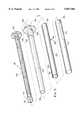
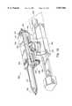
- FIG. 1is a perspective view of one embodiment of a tissue removing instrument constructed in accordance with the present disclosure
- FIG. 2is a perspective view with parts separated, of the embodiment of FIG. 1;
- FIG. 3is a partial view of the interior distal end of one handle half-section of the embodiment of FIG. 1;
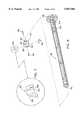
- FIG. 4is an enlarged view of the area of detail indicated in FIG. 2;
- FIG. 5is a perspective view, with parts separated, of the concentrically disposed tool mechanisms of the embodiment of FIG. 1;
- FIG. 6is a perspective view, with parts separated, of the obturator of the embodiment of FIG. 1;
- FIG. 7is an enlarged view of the area of detail indicated in FIG. 6;
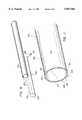
- FIG. 8is a perspective view, with parts separated, of the elongated tissue coring tube of the embodiment of FIG. 1;
- FIG. 9is a perspective view of the tissue coring tube of FIG. 8, which shows the reverse side of the distal end of the tube;
- FIG. 10is a perspective view, with parts separated, of the cutting wire and support tube of the embodiment of FIG. 1;
- FIG. 11is an enlarged perspective view of the distal end of the cutting wire positioned on the support tube
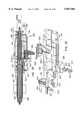
- FIG. 12is a horizontal cross-sectional view of the embodiment of FIG. 1;
- FIG. 13is an enlarged view of the indicated area of detail of the distal end of the instrument shown in FIG. 12;
- FIG. 14is an initial view showing the embodiment of FIG. 1 in use
- FIG. 15is a further view, similar to FIG. 14, showing the embodiment of FIG. 1 in use;
- FIG. 16is a horizontal cross-sectional view of the embodiment FIG. 1 with the obturator removed therefrom;
- FIG. 17is an enlarged view of the area of detail indicated in FIG. 16;
- FIG. 18is a cross-sectional view taken along section line 18--18 of FIG. 16;
- FIG. 19is a view, similar to FIG. 18, showing operational features of the instrument
- FIG. 20is a cross-sectional view of the proximal end of the embodiment of FIG. 1, showing the lockout lever in the locked position;
- FIG. 21is a view, similar to FIG. 20, showing the lockout lever in the released position
- FIG. 22is a view, similar to FIG. 17, showing the movement of the central elongated tube
- FIG. 23is a further view, similar to FIG. 14, showing the embodiment of FIG. 1 in use;
- FIG. 24is a view of the distal end of the embodiment of FIG. 1 inserted around target tissue;
- FIG. 25is a view, similar to FIG. 24, showing deployment of the cutting loop of wire and retaining strap;
- FIG. 26is a horizontal cross-sectional view showing the proximal end of the instrument during operation of the trigger
- FIG. 27is a view, similar to FIGS. 24 and 25, showing complete deployment of the cutting loop of wire and retaining strap;
- FIG. 28is a perspective view of a further embodiment constructed in accordance with the present disclosure and mounted on a cooperative portion of a stereotactic imaging machine;
- FIG. 29is a longitudinal cross-sectional view from the top of the embodiment of FIG. 28;
- FIG. 30is a perspective view, with parts separated, of the components contained in the housing or handle portion of the embodiment of FIG. 28;
- FIG. 31is a cross-sectional view taken along section line 31--31 of FIG. 29;
- FIG. 32is a cross-sectional top view of the proximal end of the embodiment of FIG. 28;
- FIG. 33is a cross-sectional view taken along section line 33--33 of FIG. 32;
- FIG. 34is a view, similar to FIG. 32, showing the operation of various elements of the embodiment of FIG. 28;
- FIG. 35is a cross-sectional view taken along section line 35--35 of FIG. 34;
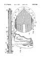
- FIG. 36is a view demonstrating a sequence of operation of the embodiment of FIG. 28 as mounted on a cooperative portion of a stereotactic imaging machine;
- FIG. 37is a view, similar to FIG. 36, demonstrating a further sequence of operation of the embodiment of FIG. 28;
- FIG. 38is a view, similar to FIG. 36, demonstrating a further sequence of operation of the embodiment of FIG. 28;
- FIG. 39is a view, similar to FIG. 36, demonstrating a further sequence of operation of the embodiment of FIG. 28;
- FIG. 40is a view, similar to FIG. 36, demonstrating a further sequence of operation of the embodiment of FIG. 28;
- FIG. 41is a perspective view of a further embodiment of a tissue removing apparatus constructed in accordance with the present disclosure.
- an instrument for removing and/or taking a biopsy of tissuein accordance with the present disclosure is designated by reference numeral 100 throughout the several views.
- the instrument 100is particularly adapted for minimally invasive insertion into tissue immediately adjacent the target tissue, and then for coring out and removing the target tissue from the patient. It will be understood by those skilled in the art, however, that the embodiments of the tissue removing instrument described herein, although generally directed to removal of breast tissue, may also be utilized for removal and/or biopsy of target tissue from other areas of a patient's body as well.
- instrument 100includes a housing such as body portion 110 (formed from handle half-sections 112 and 114), and an elongated tubular body portion 116.
- a penetrating member, such as obturator 118extends through a longitudinal passageway of instrument 100 and extends out the distal end.
- An actuator, for example trigger 120is preferably pivotally mounted in an opening formed between handle half-sections 112 and 114.
- the materials utilized in the components of the instrumentgenerally include such materials as polycarbonate for housing sections and related components, and stainless steel for components which transmit forces.
- One preferred polycarbonate materialis available from General Electric under the tradename LEXAN. It is also preferred that radiolucent materials be utilized for appropriate instrument components, e.g., elongated tubular portions, so as not to interfere with imaging of tissue positioned adjacent thereto.
- handle half-sections 112 and 114are preferably molded to have predetermined contoured regions for housing the various components as well as facilitating the instrument's operation.
- Each of the handle half-sections 112 and 114has a grip portion 122, in the shape of a pistol grip, which extends generally transversely away from a longitudinal axis "L" of a barrel portion formed when handle half-sections 112 and 114 are joined.
- Opposed semi-cylindrical walls 128 and 130form a generally cylindrical passageway with adjacent semi-cylindrical portions, i.e., raised wall portion 136 and semi-annular groove 144, from the proximal end of body 110 to the distal end thereof.
- Handle half-sections 112 and 114may be joined together by any suitable means, for example, by sonic welding, snap fit, securing screw(s), adhesive bonding or the like.
- elongated tubular portion 116includes a series of elongated components which are preferably concentrically disposed with respect to each other.
- An outer tubular sheath 132has a proximal end held securely between semi-cylindrical walls 128 and 130 and a distal end which is covered by a collar 133 securely attached thereto.
- a pair of transversely extending tab portions 134are formed at the proximal end of outer tubular sheath 132 and fit into slots 135 formed at the juncture of semi-cylindrical walls 128, 130 and raised portions 135. Tab portions 134 bias against raised portions 136 to prevent proximal movement of outer tubular sheath 132 when the instrument 100 is inserted into the body tissue.
- a tubular membersuch as central tubular shaft 138, is axially and rotatably movable within outer tubular sheath 132.
- the rotation of central tubular shaft 138may be selectively prevented by a mechanism described in detail below.
- central tubular shaft 138may be temporarily and selectively maintained in a fixed axial position relative to barrel portion 126 of body 110. This fixed axial relationship may be accomplished, for example, by a cylindrical protrusion 140 (FIG. 9) formed near the proximal end of central tubular shaft 138 being positioned in an annular groove formed by closing semi-annular groove portions 142 and 144 formed in handle half-sections 112 and 114, respectively. In this manner, central tubular shaft 138 may remain fixed axially within body 110 so as to freely rotate therein but not be removed therefrom.
- Obturator 118is slidably positioned within central tubular shaft 138 and is preferably designed to cooperate with central tubular shaft 138 so as to prevent rotation of both central tubular shaft 138 and obturator 118 during the initial insertion of instrument 100 into the patient.
- a preferred manner in which to accomplish this selective fixing of the rotational movement of both central tubular shaft 138 and obturator 118 as well as to prevent relative axial movement of those components with respect to each other as well as body 110is best shown in FIGS. 2, 3 and 5.
- a pin 146is transversely secured in elongated shaft 148 of obturator 118 near its proximal end.
- pin 146is received in a slot 150 formed in a collar 152, which is secured to the proximal end of central tubular shaft 138.
- This relationship between obturator 118 and central tubular shaft 138prevents relative rotational movement between the two components.
- the subassembly of obturator 118 and central tubular shaft 138is secured in body 110 by a bayonet-type mount, FIG.
- L-shaped groove 154is preferably provided with a lip 156 which serves to maintain pin 146 in the locked-out position.
- Lockout lever 158is pivotably mounted to body 110 and is temporarily maintained in the locked-out position by raised portions 160 extending laterally from the side surfaces of lockout lever 158 near a proximal end thereof being seated in detents 162 formed along the inner surface of handle portions of 112 and 114, respectively, at a position proximal of the groove formed by semi-annular groove portions 142 and 144.
- raised portions 160extending laterally from the side surfaces of lockout lever 158 near a proximal end thereof being seated in detents 162 formed along the inner surface of handle portions of 112 and 114, respectively, at a position proximal of the groove formed by semi-annular groove portions 142 and 144.
- Trigger 120is preferably pivotably attached to body 110 in recessed portions 164 and 166 formed in the handle half-sections 112 and 114.
- Trigger 120is connected to a tissue cutting member, e.g., a filament or wire, such as wire 168, by a pin extending through a throughbore formed near the top of trigger 120 (FIG. 16).
- Wire 168is maintained in a preferred orientation by an elongated tubular sheath 170 which is preferably concentrically disposed within outer tubular sheath 132 such that laterally extending tab portions 172 are situated adjacent tab portions 134 and maintained between housing handle half-sections 112 and 114 as described above for outer tubular sheath 132.
- a longitudinal slot 174is formed beginning at the proximal end of outer tubular sheath 132 and is disposed between laterally extending tab portions 134 so as to receive wire 168 and permit movement of the wire loop with respect to outer tubular sheath 132.
- obturator 118includes elongated shaft 148, a cutting head 176 secured to a distal end of the shaft and a knob 178 attached to a proximal end of the shaft to facilitate insertion and removal of the obturator 118 from the instrument 100.
- Cutting head 176is preferably provided with slots 180 and 182, formed orthogonally with respect to each other and which are dimensioned to receive individual blades 184 such that a cutting edge 186 formed on each blade 184 is angled to correspond to the angled distal surfaces 188 of the cutting head 176.
- individual blades 134are each provided with a transversely extending slot 188 having a series of individual tooth members 190 extending from the side wall of the slot.
- Teeth 190are preferably formed in the shape of a ramp-shaped camming surface to interlock with complimentary surfaces (not shown) formed within orthogonally disposed slots 180 and 182.
- Cutting head 176is in the shape of a plug member having a proximally extending portion 192 of reduced diameter which is inserted into a bore 194 formed at the distal end of obturator 118 so as to be fixedly secured thereto. Any suitable known techniques for mounting may be utilized, such as friction fitting, bonding, adhesives or the like.
- central tubular shaft 138has a tissue cutting surface, such as annular cutting edge 196 formed at the distal end to facilitate coring of the tissue surrounding and including the target tissue within the patient.
- the shaftis preferably formed of a material suitable for forming a sharpened edge, such as, for example, stainless steel.
- a knob 198is secured to the proximal end of central tubular shaft 138, for example, by locking tabs 200 engaging cut out portions 202 formed in cylindrical section 152 of knob 198.
- Knob 198is preferably further provided with a knurled gripping surface 206 to facilitate rotation of the shaft during the coring action of the tissue. Such rotational movement is facilitated by the disposition of pin 140 within the annular groove formed by semi-annular groove portions 142 and 144, as noted above.
- wire 168facilitates the severing of the tissue core to permit removal of the targeted tissue from the patient and, optionally, delivers electrocautery current to the tissue as cutting is accomplished.
- Wire 168is preferably formed of a single length of thin gauge, stainless steel wire which is bent to an initial configuration or pre-fired condition contained within instrument 100, as shown in FIG. 10.
- wire 168is folded in half such that free ends 208 and 210 are positioned at the proximal end and are formed into a U-shaped bend to hook around pin 212 disposed at the top of trigger 120 (FIGS. 2 and 17).
- Wire 168extends longitudinally along the outer surface of elongated tubular sheath 170 to the distal end thereof.
- a circular loop 213is formed at the distal end of wire 168 and is positioned adjacent a flange 214 formed at the distal end of the tubular sheath 170.
- Flange 214is provided with radially extending leg portions 218 which form diametrically opposed passageways which hold wire 168 in a position substantially aligned with the distal end of tubular sheath 170.
- a tissue retaining membersuch as strap 216, is wrapped around circular loop 213 and is provided with a tabbed end portion 220 to maintain the positioning of the strap across the distal opening of elongated tubular sheath upon cutting of the tissue core, which will explained in greater detail herein.
- FIG. 12The relative positioning of the various structural subassemblies in the initial configuration of instrument 100 is shown in the longitudinal cross-sectional view of FIG. 12.
- obturator 118is shown inserted in instrument 100 with lockout lever 158 preventing proximal movement of central tubular shaft 138.
- wire 168is maintained in position by central tubular shaft 138 and obturator 118 on the interior side and by collar 133 on the exterior side. Wire 168 cannot be deployed to cut tissue until both obturator 118 and central tubular shaft 138 are moved distally of loop 213 (FIG. 10).
- FIGS. 14-27A preferred method of using instrument 100 is illustrated in FIGS. 14-27.
- Instrument 100is inserted into the breast tissue along a predetermined path toward the target tissue 222.
- the location of the target tissuecan be specifically determined through the use of known localization techniques, such as for example, the insertion of a localization needle and/or the use of a stereotactic mammography device.
- the target tissuemay be tagged with a tagging device and instrument 100 moved adjacent the tagged location under conventional imaging guidance, or instrument 100 may be adapted to move along a target tissue locating device, such as a conventional K-wire, which was pre-positioned adjacent or across the target tissue.
- Instrument 100may cooperate with a target tissue locating device in a variety of manners such as sliding coaxially along such locating device.
- obturator 118is first rotated in a counterclockwise fashion as indicated by arrow "A” in FIG. 14, by the user gripping knob 178 and rotating the knob in a counterclockwise fashion. This rotational movement disengages pin 146 from L-shaped groove 154 (FIGS. 3 and 6) to permit axial movement of obturator 118 relative to the instrument 100.
- obturator 118may be removed from the instrument 100 by pulling on knob 178 in a proximal direction as indicated by arrow "B" in FIG. 14.
- the target tissueis cored out from the surrounding tissue by urging instrument 100 in a proximal direction as indicated by arrow "C” in FIG. 15, while simultaneously turning knob 198 of central tubular shaft 138 to cause rotation of annular cutting edge 196 at the distal end of the central tubular shaft 138.
- Rotation of the elongated central tubular shaft 138may be in either a clockwise or counterclockwise direction or both depending on the preference of the user, as indicated by arrow "D" in FIG. 15.
- central tubular shaft 138When the target tissue is completely within the distal end of instrument 100, central tubular shaft 138 is moved proximally to allow for deployment of wire loop 168 to sever the tissue core from the patient. Electrocautery current is optionally delivered to the tissue by wire loop 168 as severing is accomplished. As shown in FIGS. 16 and 17, elongated central tubular shaft 138 is shown extending distally from the distal end of instrument 100 and preventing wire loop 168 from moving out of alignment with the circumferential alignment with the distal end of elongated tubular sheath 170.
- FIG. 18shows the relative positioning of pin 140 within annular groove 141 to facilitate the rotation of elongated central tubular shaft 138 therein. Such rotation is possible when the obturator 118 is removed from instrument 100.
- knob 198is rotated, as indicated by arrow "E” in FIG. 19, to align pin 140 with a keyway 224 formed in handle half-sections 112 and 114. This alignment permits proximal movement of central tubular shaft 138 when lever lockout 158 is pushed down, as indicated by arrow “F” in FIG. 21, to release protrusion 160 from detent 162 (FIGS. 2 and 4).
- Knob 198is pulled proximally as indicated by arrow "G” in FIG. 21 to move the distal end of central tubular shaft 138 proximal of wire loop 213.
- Instrument 100may thus be removed from the patient's breast. Due to the partial obstruction of the distal end opening of elongated tubular sheath 170 by strap 214, the severed tissue core will be removed from the patient with instrument 100. To the extent necessary, the puncture wound left by instrument 100 may be closed by any suitable known suturing techniques.
- FIGS. 28-40Another embodiment of the presently disclosed instrument for removing and/or taking a biopsy of target tissue and a method of its use are illustrated in FIGS. 28-40.
- instrument 300is particularly adapted for use on a precision instrument positioning machine, for example, a stereotactic imaging machine.
- a precision instrument positioning machinefor example, a stereotactic imaging machine.
- Such devicesare commercially available, for example, from Lorad Corporation of Danbury, Conn.
- An example of such a machineis disclosed in U.S. Pat. No. 5,289,520 which issued Feb. 22, 1994 to Pellegrino et al., the contents of which are hereby incorporated by reference.
- stereotactic machinesfacilitate stereo x-ray imaging of a patient's breast using a three dimensional coordinate system, while the patient is in a prone position on a specially designed table.
- An openingis provided on the table to permit the patient's breast to be pendulantly disposed therethrough and a clamp is used to fix the exact location of the patient's pendulant breast relative to the operational components of the machine which facilitate precision interaction of instrumentation with the breast, i.e. for biopsy or tissue removal.
- instrument 300is shown mounted in place on the instrument positioning control mechanism of a stereotactic machine, generally designated by reference numeral 302.
- Stereotactic machine 302has an instrument mount 304, the movement of which is coordinated with the imaging capabilities of the machine.
- the instrument mount 304is provided with a standardized instrument or tool mounting bracket 305 to facilitate mounting of various surgical instruments which can take advantage of the precision positioning features of the stereotactic machine. This is particularly beneficial in procedures where the target tissue is not palpable.
- the cooperative structures on instrument 300 and stereotactic machine 302may be reconfigured so that more structure is included on instrument 300 and less on machine 302, or vice versa. All that is required is that stereotactic machine 302 and instrument 300 cooperate so as to position instrument 300 as desired with respect to the target tissue.
- Instrument 300is provided with four slide mounts 306, two of which are formed on each side of housing half-sections 312 and 314 so that instrument 300 can be mounted on either side.
- the mechanical operational controls of instrument 300all of which are positioned on the same side of the instrument, may be oriented to suit the preference of the personnel using the instrument during the particular procedure. It is envisioned that some of the control actuators of instrument 300 may be reconfigured so that they would be operable from a different side than the remaining control actuators.
- Housing half-sections 312 and 314are preferably molded to conform to the dimensions of the stereotactic machine tool mounting bracket 305, for example, a rectangular base dimension.
- Obturator 318has a pair of resiliently formed retaining members 319 each of which include a shoulder portion 321 which engages a cut-out portion of the proximal end wall of housing half-section 314 to maintain obturator 318 in place during insertion of instrument 300.
- a firing lockout mechanismis provided to prevent premature movement of the cutting wire before obturator 318 and central tubular shaft 338 are properly positioned relative to the wire loop positioned at the distal end of wire 368 (similar to loop 213 of wire 168).
- the firing lockout mechanismincludes a safety lockout member 323 and a control member, such as slide bar member 341.
- Lockout member 323is slidably received in a cutout 325 formed in a sidewall of housing half-section 314 and has a pair of slotted keyways 327 and 329 formed thereon.
- raised portions 331which provide tactile indication to the user of the relative positioning of lockout member 323 during a two-stage lockout release process described below.
- Trigger 320is provided with a retaining pin 333 which has a pair of bores formed therethrough to receive and frictionally retain wire loop 368.
- a latch portion 335is formed extending from the distal side of trigger 320 which is configured and dimensioned to interact with lockout member 323 and specifically to slide in keyway 327.
- Central tubular shaft 338is fitted at a proximal end with gear collar 337, the teeth of which are designed to mesh with the teeth of gear 339 which is manually driven by a drive mechanism.
- a powered drive mechanismmay be provided on stereotactic machine 302.
- a slide bar 341cradles gear collar 337 to permit rotational movement thereof while controlling the axial alignment of central tubular shaft 338 within housing half-sections 312 and 314.
- Slide bar 341is provided with a latch portion 343 formed at a proximal end thereof. At the distal end, slide bar 341 has actuator button 345 to facilitate proximal movement of slide bar 341 by the user.
- Another feature of slide bar 341is a diagonal groove 347 which is formed in the side surface adjacent the proximal end of the slide bar to permit wire loop 368 to slidably pass therethrough, as best seen in FIG. 29.
- FIGS. 31-35The two stage lockout process of lockout member 323 is best shown in FIGS. 31-35 in conjunction with FIGS. 36-40.
- FIGS. 36 and 37it is desirable to maintain the relative axial positioning of central tubular shaft 338 with respect to outer tubular sheath 332 as well as to prevent firing of trigger 320.
- Both of these preventive goalsare accomplished when obturator 318 is positioned within the instrument and lockout member 323 is maintained in its initial position as shown in FIG. 29 by obturator member 318 and shoulder portion 349 of lockout member 323 biasing against the outer wall of housing half-section 314. In this position, keyways 327 and 329 of lockout member 323 are maintained out of alignment with slide bar 341 and latch portion 335 of trigger 320, respectively.
- obturator 318is removed (FIGS. 29 and 38) by pressing radially inwardly on retaining members 319 to disengage the retaining members from shoulder portions 321 from the proximal end wall of housing half-section 314.
- lockout member 323is free to move transversely toward the central longitudinal axis of instrument 300.
- the first stage of releasing lockout member 323, illustrated in FIG. 32,is accomplished when the user pushes lockout member 323 inwardly toward the center of the instrument. A tactile indication is felt by the user when the first raised portion 331 passes over the side wall of housing half-section 314.
- Actuator button 345is moved proximally, as indicated by arrow "J" in FIG. 32, to effect proximal movement of central tubular shaft 138. This proximal movement is limited by partition 351 formed transversely across housing half-section 314.
- latch portionpasses through keyway 327 and prevents further transverse movement of lockout member 323 until latch portion 343 passes completely through keyway 327.
- lockout member 323is again pushed transversely inward (see FIGS. 32 and 33) until the user feels another tactile indication, resulting from the second raised portion 331 crossing over the side wall of housing half-section 314.
- latch 335 of trigger 320is aligned with keyway 329.
- Trigger 320is moved proximally in the direction of arrow "K”.
- latch portion 343 of slide bar 341is in engagement with lockout member 323 to prevent distal movement of slide bar 341 and, therefore, central tubular shaft 338, during firing of trigger 320.
- FIG. 41A further embodiment of a tissue removing instrument is shown in FIG. 41.
- Instrument 400is similar to the embodiment of FIGS. 28-40 and is designed to be inserted and used manually by a surgeon, rather than in conjunction with a stereotactic machine.
- the handle of instrument 400includes handle half-sections 412 and 414 which are molded to a dimension suitable for being held in the palm of either the user's left or right hands.
- the control mechanisms of instrument 400may be the same as those for instrument 300 or lockout member 323 may be eliminated as shown in FIG. 41.
- the basic manner of usage of instrumentis the same as that for instrument 300.
Landscapes
- Health & Medical Sciences (AREA)
- Life Sciences & Earth Sciences (AREA)
- Surgery (AREA)
- Biomedical Technology (AREA)
- Engineering & Computer Science (AREA)
- Pathology (AREA)
- Heart & Thoracic Surgery (AREA)
- Medical Informatics (AREA)
- Molecular Biology (AREA)
- Animal Behavior & Ethology (AREA)
- General Health & Medical Sciences (AREA)
- Public Health (AREA)
- Veterinary Medicine (AREA)
- Nuclear Medicine, Radiotherapy & Molecular Imaging (AREA)
- Surgical Instruments (AREA)
Abstract
Description
Claims (29)
Priority Applications (9)
| Application Number | Priority Date | Filing Date | Title |
|---|---|---|---|
| US08/525,450US5857982A (en) | 1995-09-08 | 1995-09-08 | Apparatus and method for removing tissue |
| US08/546,482US5817034A (en) | 1995-09-08 | 1995-10-20 | Apparatus and method for removing tissue |
| DE29623929UDE29623929U1 (en) | 1995-09-08 | 1996-09-06 | Device for removing tissue |
| EP00117346AEP1051946A3 (en) | 1995-09-08 | 1996-09-06 | Apparatus and method for removing tissue |
| CA002184973ACA2184973A1 (en) | 1995-09-08 | 1996-09-06 | Apparatus and method for removing tissue |
| EP96114296AEP0761170A3 (en) | 1995-09-08 | 1996-09-06 | Apparatus for removing tissue |
| US09/158,632US6213957B1 (en) | 1995-09-08 | 1998-09-22 | Apparatus and method for removing tissue |
| US09/178,730US6036657A (en) | 1995-09-08 | 1998-10-26 | Apparatus for removing tissue |
| US09/812,465US20010020139A1 (en) | 1995-09-08 | 2001-03-20 | Apparatus and method for removing tissue |
Applications Claiming Priority (1)
| Application Number | Priority Date | Filing Date | Title |
|---|---|---|---|
| US08/525,450US5857982A (en) | 1995-09-08 | 1995-09-08 | Apparatus and method for removing tissue |
Related Child Applications (2)
| Application Number | Title | Priority Date | Filing Date |
|---|---|---|---|
| US08/546,482Continuation-In-PartUS5817034A (en) | 1995-09-08 | 1995-10-20 | Apparatus and method for removing tissue |
| US09/178,730ContinuationUS6036657A (en) | 1995-09-08 | 1998-10-26 | Apparatus for removing tissue |
Publications (1)
| Publication Number | Publication Date |
|---|---|
| US5857982Atrue US5857982A (en) | 1999-01-12 |
Family
ID=24093311
Family Applications (3)
| Application Number | Title | Priority Date | Filing Date |
|---|---|---|---|
| US08/525,450Expired - LifetimeUS5857982A (en) | 1995-09-08 | 1995-09-08 | Apparatus and method for removing tissue |
| US09/178,730Expired - LifetimeUS6036657A (en) | 1995-09-08 | 1998-10-26 | Apparatus for removing tissue |
| US09/812,465AbandonedUS20010020139A1 (en) | 1995-09-08 | 2001-03-20 | Apparatus and method for removing tissue |
Family Applications After (2)
| Application Number | Title | Priority Date | Filing Date |
|---|---|---|---|
| US09/178,730Expired - LifetimeUS6036657A (en) | 1995-09-08 | 1998-10-26 | Apparatus for removing tissue |
| US09/812,465AbandonedUS20010020139A1 (en) | 1995-09-08 | 2001-03-20 | Apparatus and method for removing tissue |
Country Status (1)
| Country | Link |
|---|---|
| US (3) | US5857982A (en) |
Cited By (88)
| Publication number | Priority date | Publication date | Assignee | Title |
|---|---|---|---|---|
| US6036698A (en)* | 1998-10-30 | 2000-03-14 | Vivant Medical, Inc. | Expandable ring percutaneous tissue removal device |
| EP1093757A1 (en)* | 1999-10-18 | 2001-04-25 | Ethicon Endo-Surgery, Inc. | Methods and devices for collection of soft tissue |
| US6248081B1 (en)* | 1999-09-28 | 2001-06-19 | Scimed Life Systems, Inc. | Endoscopic submucosal core biopsy device |
| US6267732B1 (en)* | 1997-09-12 | 2001-07-31 | Imagyn Medical Technologies, Inc. | Incisional breast biopsy device |
| US6277083B1 (en) | 1999-12-27 | 2001-08-21 | Neothermia Corporation | Minimally invasive intact recovery of tissue |
| US6287304B1 (en) | 1999-10-15 | 2001-09-11 | Neothermia Corporation | Interstitial cauterization of tissue volumes with electrosurgically deployed electrodes |
| US6344026B1 (en) | 1998-04-08 | 2002-02-05 | Senorx, Inc. | Tissue specimen encapsulation device and method thereof |
| US6383145B1 (en) | 1997-09-12 | 2002-05-07 | Imagyn Medical Technologies California, Inc. | Incisional breast biopsy device |
| US6471659B2 (en) | 1999-12-27 | 2002-10-29 | Neothermia Corporation | Minimally invasive intact recovery of tissue |
| US6514248B1 (en) | 1999-10-15 | 2003-02-04 | Neothermia Corporation | Accurate cutting about and into tissue volumes with electrosurgically deployed electrodes |
| US20030045834A1 (en)* | 2001-08-31 | 2003-03-06 | Conmed Corporation | Obturator and cannula for a trocar adapted for ease of insertion and removal |
| US20030060770A1 (en)* | 2001-08-31 | 2003-03-27 | Conmed Corporation | Trocar system |
| US6540695B1 (en) | 1998-04-08 | 2003-04-01 | Senorx, Inc. | Biopsy anchor device with cutter |
| US6551253B2 (en) | 1997-09-12 | 2003-04-22 | Imagyn Medical Technologies | Incisional breast biopsy device |
| US6659105B2 (en) | 1998-02-26 | 2003-12-09 | Senorx, Inc. | Tissue specimen isolating and damaging device and method |
| USD495054S1 (en) | 2001-08-31 | 2004-08-24 | Conmed Corporation | Cannula head |
| USD495053S1 (en) | 2001-08-31 | 2004-08-24 | Conmed Corporation | Trocar |
| US20050038462A1 (en)* | 1998-04-08 | 2005-02-17 | Senorx, Inc. | Dilation devices and methods for removing tissue specimens |
| US20050065453A1 (en)* | 2003-02-24 | 2005-03-24 | Senorx, Inc. | Biopsy device with selectable tissue receiving aperture orientation and site illumination |
| US20050159677A1 (en)* | 2003-12-23 | 2005-07-21 | Shabaz Martin V. | Biopsy device with aperture orientation and improved tip |
| US20050187489A1 (en)* | 1998-03-03 | 2005-08-25 | Wardle John L. | Electrosurgical specimen-collection system |
| US6955676B2 (en) | 1999-06-22 | 2005-10-18 | Senorx, Inc. | Shaped scalpel |
| US20060030785A1 (en)* | 2004-05-11 | 2006-02-09 | Inrad, Inc. | Core biopsy device |
| US20060173377A1 (en)* | 2005-01-31 | 2006-08-03 | Mccullough Adam B | Quick cycle biopsy system |
| US20060184192A1 (en)* | 2005-02-11 | 2006-08-17 | Markworth Aaron D | Systems and methods for providing cavities in interior body regions |
| US20060224084A1 (en)* | 2005-04-05 | 2006-10-05 | Vetter James W | Methods and devices for removing tissue from a patient |
| US20060229528A1 (en)* | 2003-03-29 | 2006-10-12 | C. R. Brad, Inc. | Coaxial cannula provided with a sealing element |
| US20070038146A1 (en)* | 2005-08-05 | 2007-02-15 | Quick Richard L | Biopsy device with fluid delivery to tissue specimens |
| US7189206B2 (en) | 2003-02-24 | 2007-03-13 | Senorx, Inc. | Biopsy device with inner cutter |
| US20070149894A1 (en)* | 2002-03-19 | 2007-06-28 | C.R. Bard, Inc. | Biopsy device for removing tissue specimens using a vacuum |
| US20070149893A1 (en)* | 2002-03-19 | 2007-06-28 | C.R. Bard, Inc. | Biopsy device and biopsy needle module that can be inserted into the biopsy device |
| USD559387S1 (en) | 2001-08-31 | 2008-01-08 | Conmed Corporation | Cannula tube |
| US20080009875A1 (en)* | 2006-07-07 | 2008-01-10 | Meera Sankaran | Medical device with dual expansion mechanism |
| WO2008020439A2 (en) | 2006-08-17 | 2008-02-21 | Sialo Technology Israel Ltd | All-in-one optical microscopic handle |
| US20080058675A1 (en)* | 2004-12-16 | 2008-03-06 | Senorx, Inc. | Biopsy device with aperture orientation and improved tip |
| US20080125782A1 (en)* | 2006-11-29 | 2008-05-29 | Disc Dynamics, Inc. | Method and apparatus for removing an extension from a prosthesis |
| US20090012423A1 (en)* | 2004-05-11 | 2009-01-08 | Inrad, Inc. | Core Biopsy Device |
| WO2009012392A1 (en) | 2007-07-17 | 2009-01-22 | Neal Marc Lonky | Frictional trans-epithelial tissue disruption and collection apparatus and method of inducing and/or augmenting an immune response |
| US20090112118A1 (en)* | 2005-08-05 | 2009-04-30 | Senorx, Inc. | Biopsy device with fluid delivery to tissue specimens |
| US20090112119A1 (en)* | 2007-10-31 | 2009-04-30 | Kim Stanley I | Rotating biopsy device and biopsy robot |
| US20090204021A1 (en)* | 2004-12-16 | 2009-08-13 | Senorx, Inc. | Apparatus and method for accessing a body site |
| US20090270862A1 (en)* | 2008-04-25 | 2009-10-29 | Greg Arcenio | Medical device with one-way rotary drive mechanism |
| US20090270892A1 (en)* | 2008-04-25 | 2009-10-29 | Greg Arcenio | Steerable medical device for tissue disruption |
| US20090270893A1 (en)* | 2008-04-25 | 2009-10-29 | Greg Arcenio | Medical device for tissue disruption with serrated expandable portion |
| US20100030216A1 (en)* | 2008-07-30 | 2010-02-04 | Arcenio Gregory B | Discectomy tool having counter-rotating nucleus disruptors |
| US7762961B2 (en) | 2003-03-29 | 2010-07-27 | C. R. Bard, Inc. | Pressure generating unit |
| US20100210967A1 (en)* | 2007-08-02 | 2010-08-19 | Sjunnesson Haakan | Surgical kits and methods |
| US20110054349A1 (en)* | 2007-12-27 | 2011-03-03 | Devicor Medical Products, Inc. | Clutch and valving system for tetherless biopsy device |
| US20110172557A1 (en)* | 2007-07-17 | 2011-07-14 | Histologics Llc | Frictional trans-epithelial tissue disruption collection apparatus and method of inducing an immune response |
| US20110190661A1 (en)* | 2007-10-25 | 2011-08-04 | Epitome Pharmaceuticals Limited | Tissue Splitting Biopsy Needle |
| WO2011123446A1 (en) | 2010-03-30 | 2011-10-06 | Flatland Martin L | Tissue excision device |
| US8052615B2 (en) | 2004-07-09 | 2011-11-08 | Bard Peripheral Vascular, Inc. | Length detection system for biopsy device |
| US8251917B2 (en) | 2006-08-21 | 2012-08-28 | C. R. Bard, Inc. | Self-contained handheld biopsy needle |
| US20120226191A1 (en)* | 2011-03-04 | 2012-09-06 | Neoh Wenhong | Ergonomic biopsy instrument |
| US8262585B2 (en) | 2005-08-10 | 2012-09-11 | C. R. Bard, Inc. | Single-insertion, multiple sampling biopsy device with linear drive |
| US8262586B2 (en) | 2006-10-24 | 2012-09-11 | C. R. Bard, Inc. | Large sample low aspect ratio biopsy needle |
| US8267868B2 (en) | 2005-08-10 | 2012-09-18 | C. R. Bard, Inc. | Single-insertion, multiple sample biopsy device with integrated markers |
| US8282574B2 (en) | 2005-08-10 | 2012-10-09 | C. R. Bard, Inc. | Single-insertion, multiple sampling biopsy device usable with various transport systems and integrated markers |
| US8430824B2 (en) | 2009-10-29 | 2013-04-30 | Bard Peripheral Vascular, Inc. | Biopsy driver assembly having a control circuit for conserving battery power |
| US8485989B2 (en) | 2009-09-01 | 2013-07-16 | Bard Peripheral Vascular, Inc. | Biopsy apparatus having a tissue sample retrieval mechanism |
| US8485987B2 (en) | 2006-10-06 | 2013-07-16 | Bard Peripheral Vascular, Inc. | Tissue handling system with reduced operator exposure |
| US8597206B2 (en) | 2009-10-12 | 2013-12-03 | Bard Peripheral Vascular, Inc. | Biopsy probe assembly having a mechanism to prevent misalignment of components prior to installation |
| US8597205B2 (en) | 2007-12-20 | 2013-12-03 | C. R. Bard, Inc. | Biopsy device |
| US8641640B2 (en) | 2005-05-23 | 2014-02-04 | Senorx, Inc. | Tissue cutting member for a biopsy device |
| US8690793B2 (en) | 2009-03-16 | 2014-04-08 | C. R. Bard, Inc. | Biopsy device having rotational cutting |
| US8708930B2 (en) | 2009-04-15 | 2014-04-29 | Bard Peripheral Vascular, Inc. | Biopsy apparatus having integrated fluid management |
| US8845548B2 (en) | 2009-06-12 | 2014-09-30 | Devicor Medical Products, Inc. | Cutter drive assembly for biopsy device |
| US9044213B1 (en) | 2010-03-26 | 2015-06-02 | Histologics, LLC | Frictional tissue sampling and collection method and device |
| US9173641B2 (en) | 2009-08-12 | 2015-11-03 | C. R. Bard, Inc. | Biopsy apparatus having integrated thumbwheel mechanism for manual rotation of biopsy cannula |
| US9216012B2 (en) | 1998-09-01 | 2015-12-22 | Senorx, Inc | Methods and apparatus for securing medical instruments to desired locations in a patient's body |
| US9241734B2 (en) | 2012-12-12 | 2016-01-26 | Covidien Lp | Tissue-removing catheter including screw blade and cutter driveshaft |
| US9532797B2 (en) | 2012-12-12 | 2017-01-03 | Covidien Lp | Tissue-removing catheter including urging mechanism |
| US9549718B2 (en) | 2012-12-12 | 2017-01-24 | Covidien Lp | Tissue-removing catheter for body lumen |
| US9549755B2 (en) | 2012-12-12 | 2017-01-24 | Covidien Lp | Cutter for tissue-removing catheter |
| US9636138B2 (en) | 2012-12-12 | 2017-05-02 | Covidien Lp | Tissue-removing catheter including force-transmitting member for actuating a cutter housing |
| US9636139B2 (en) | 2012-12-12 | 2017-05-02 | Covidien Lp | Tissue-removing catheter with ball and socket deployment mechanism |
| US10201332B1 (en) | 2012-12-03 | 2019-02-12 | Healoe Llc | Device and method of orienting a biopsy device on epithelial tissue |
| US10251630B2 (en) | 2015-08-28 | 2019-04-09 | SiteSelect Inc. | Tissue excision device with anchor stability rod and anchor stability rod |
| US10285673B2 (en) | 2013-03-20 | 2019-05-14 | Bard Peripheral Vascular, Inc. | Biopsy device |
| US10456120B2 (en) | 2013-11-05 | 2019-10-29 | C. R. Bard, Inc. | Biopsy device having integrated vacuum |
| US10456161B2 (en) | 2016-04-14 | 2019-10-29 | Covidien Lp | Tissue-removing catheter with adjustment mechanism |
| US10463350B2 (en) | 2015-05-01 | 2019-11-05 | C. R. Bard, Inc. | Biopsy device |
| US11013466B2 (en) | 2016-01-28 | 2021-05-25 | Healoe, Llc | Device and method to control and manipulate a catheter |
| US11116483B2 (en) | 2017-05-19 | 2021-09-14 | Merit Medical Systems, Inc. | Rotating biopsy needle |
| US11793498B2 (en) | 2017-05-19 | 2023-10-24 | Merit Medical Systems, Inc. | Biopsy needle devices and methods of use |
| US11844500B2 (en) | 2017-05-19 | 2023-12-19 | Merit Medical Systems, Inc. | Semi-automatic biopsy needle device and methods of use |
| US12150627B2 (en) | 2019-12-11 | 2024-11-26 | Merit Medical Systems, Inc. | Bone biopsy device and related methods |
| US12295556B2 (en) | 2019-09-27 | 2025-05-13 | Merit Medical Systems, Inc. | Rotation biopsy system and handle |
Families Citing this family (42)
| Publication number | Priority date | Publication date | Assignee | Title |
|---|---|---|---|---|
| US7687057B2 (en) | 1998-01-09 | 2010-03-30 | Yissum Research Development Company Of The Hebrew University Of Jerusalem | In vitro micro-organs, and uses related thereto |
| US20030152562A1 (en)* | 2001-10-23 | 2003-08-14 | Yissum Research Development Company Of The Hebrew University Of Jerusalem | Vitro micro-organs, and uses related thereto |
| WO2004017849A1 (en)* | 1999-10-27 | 2004-03-04 | Neothermia Corporation | Device and method for minimally invasive and intact recovery of tissue |
| US6656189B1 (en) | 2000-05-25 | 2003-12-02 | Synthes (Usa) | Radiolucent aiming guide |
| US8088568B2 (en) | 2001-11-05 | 2012-01-03 | Medgentics, Inc. | Dermal micro-organs, methods and apparatuses for producing and using the same |
| US7468242B2 (en)* | 2001-11-05 | 2008-12-23 | Medgenics, Inc. | Dermal micro organs, methods and apparatuses for producing and using the same |
| KR100969344B1 (en)* | 2001-11-05 | 2010-07-09 | 메드제닉스 인코포레이티드 | Closed automated system for tissue-based treatment, methods of dosing and administering using the same |
| US8501396B2 (en) | 2001-11-05 | 2013-08-06 | Medgenics Medical Israel Ltd. | Dermal micro-organs, methods and apparatuses for producing and using the same |
| US6981949B2 (en) | 2002-06-06 | 2006-01-03 | Ethicon Endo-Surgery, Inc. | Perimeter cut biopsy probe |
| US7066893B2 (en)* | 2002-06-06 | 2006-06-27 | Ethicon Endo-Surgery, Inc. | Biopsy method |
| AU2003242967A1 (en)* | 2002-07-12 | 2004-02-02 | Yissum Research Development Company Of The Hebrew University Of Jerusalem | Method and device for inducing biological processes by micro-organs |
| EP2377404A1 (en)* | 2003-05-01 | 2011-10-19 | Medgenics, Inc. | A dermal micro-organ which is an explant of living tissue |
| US7169114B2 (en)* | 2003-06-04 | 2007-01-30 | Krause William R | Biopsy and delivery device |
| JP4653115B2 (en)* | 2003-12-16 | 2011-03-16 | アイデックス ラボラトリーズ インコーポレイテッド | Tissue sampling device |
| US20060058826A1 (en)* | 2004-08-25 | 2006-03-16 | Evans Avery J | Tissue cavitation device |
| US7481815B2 (en) | 2004-09-23 | 2009-01-27 | Synthes (U.S.A.) | Coplanar X-ray guided aiming arm for locking of intramedullary nails |
| US20070010823A1 (en)* | 2005-07-11 | 2007-01-11 | Cannuflow, Inc. | Arthroscopic shaver system |
| US9192398B2 (en)* | 2005-09-19 | 2015-11-24 | DePuy Synthes Products, Inc. | Orthopedic implant insertion handle and aiming guide |
| US10368899B2 (en)* | 2006-01-13 | 2019-08-06 | Heartware, Inc. | Surgical tool for coring precise holes and providing for retrieval of tissue |
| US8454948B2 (en) | 2006-09-14 | 2013-06-04 | Medgenics Medical Israel Ltd. | Long lasting drug formulations |
| AU2007294858B2 (en)* | 2006-09-14 | 2011-05-12 | Medgenics Medical Israel, Ltd | Long lasting drug formulations |
| AU2007334420B2 (en)* | 2006-12-15 | 2013-03-14 | Covidien Lp | Trocar assembly with obturator design |
| EP2120740A1 (en)* | 2007-02-02 | 2009-11-25 | Synthes GmbH | Tunnel tool for soft tissue |
| AU2008243046B2 (en) | 2007-04-18 | 2013-06-06 | Covidien Lp | Trocar assembly with obturator dissector |
| US8282663B2 (en) | 2007-10-05 | 2012-10-09 | Tyco Healthcare Group Lp | Bladeless obturator for use in a surgical trocar assembly |
| ES2442241T3 (en) | 2008-03-31 | 2014-02-10 | Applied Medical Resources Corporation | Electrosurgical system with a switching mechanism |
| USD604847S1 (en)* | 2008-06-13 | 2009-11-24 | Karl Storz Gmbh & Co. Kg | Morcellator |
| GB2469082A (en)* | 2009-03-31 | 2010-10-06 | Nhs Innovations South East | Surgical Instrument for Biopsy |
| US8979883B2 (en) | 2009-12-17 | 2015-03-17 | Covidien Lp | Obturator tip |
| US9226774B2 (en) | 2009-12-17 | 2016-01-05 | Covidien Lp | Visual obturator with tip openings |
| AU2011268458B2 (en) | 2010-06-15 | 2014-06-12 | Medgenics Medical Israel Ltd. | Long lasting drug formulations |
| US8961552B2 (en) | 2010-09-21 | 2015-02-24 | Covidien Lp | Bladeless obturators and bladeless obturator members |
| AU2011308509B8 (en) | 2010-10-01 | 2015-04-02 | Applied Medical Resources Corporation | Electrosurgical instrument |
| EP2797521B1 (en)* | 2011-12-29 | 2015-12-09 | Synthes GmbH | Suprapatellar insertion system |
| EP3158952B1 (en)* | 2012-09-14 | 2019-10-23 | Synthes GmbH | Multihole drill sleeve with protection sleeve |
| EP2961337B1 (en)* | 2013-02-28 | 2021-04-28 | Feibel, Jonathan | Systems and apparatuses for reaming bone elements |
| WO2015176074A2 (en) | 2014-05-16 | 2015-11-19 | Applied Medical Resources Corporation | Electrosurgical system |
| JP6735272B2 (en) | 2014-05-30 | 2020-08-05 | アプライド メディカル リソーシーズ コーポレイション | Electrosurgical sealing and incision system |
| KR102545505B1 (en) | 2014-12-23 | 2023-06-20 | 어플라이드 메디컬 리소시스 코포레이션 | Bipolar Electrosurgical Sealers and Dividers |
| USD748259S1 (en) | 2014-12-29 | 2016-01-26 | Applied Medical Resources Corporation | Electrosurgical instrument |
| JP7610777B2 (en) | 2018-09-05 | 2025-01-09 | アプライド メディカル リソーシーズ コーポレイション | Electrosurgical Generator Control System |
| US11696796B2 (en) | 2018-11-16 | 2023-07-11 | Applied Medical Resources Corporation | Electrosurgical system |
Citations (51)
| Publication number | Priority date | Publication date | Assignee | Title |
|---|---|---|---|---|
| DE263228C (en)* | ||||
| US1568008A (en)* | 1925-05-09 | 1925-12-29 | Cecil C Thomas | Implement for removing cores from citrous fruits |
| US1609456A (en)* | 1925-12-03 | 1926-12-07 | Charles H Boyle | Coring device |
| US1615494A (en)* | 1922-10-12 | 1927-01-25 | John L Waring | Tonsil-removing apparatus |
| US2117278A (en)* | 1937-09-07 | 1938-05-17 | George C Ainsworth | Fruit corer |
| US2541542A (en)* | 1946-02-13 | 1951-02-13 | Perez Guillermo Herrera | Trocar for biopsia |
| US3470867A (en)* | 1964-11-23 | 1969-10-07 | Sidney Goldsmith | Biopsy needle |
| US3477423A (en)* | 1967-01-09 | 1969-11-11 | Baxter Laboratories Inc | Biopsy instrument |
| US3605721A (en)* | 1969-11-03 | 1971-09-20 | Ismet Hallac | Biopsy needle |
| US3628524A (en)* | 1969-02-28 | 1971-12-21 | Khosrow Jamshidi | Biopsy needle |
| CH534505A (en)* | 1969-06-30 | 1973-03-15 | Hubert Dr Reinisch | Biopsy collection device |
| US4010737A (en)* | 1971-06-14 | 1977-03-08 | Vilaghy Miklos I | Bone biopsy instrument kit |
| US4099518A (en)* | 1976-05-10 | 1978-07-11 | Baylis Shelby M | Biopsy apparatus |
| US4174715A (en)* | 1977-03-28 | 1979-11-20 | Hasson Harrith M | Multi-pronged laparoscopy forceps |
| US4177797A (en)* | 1977-03-04 | 1979-12-11 | Shelby M. Baylis | Rotary biopsy device and method of using same |
| US4306570A (en)* | 1980-08-20 | 1981-12-22 | Matthews Larry S | Counter rotating biopsy needle |
| WO1982001988A1 (en)* | 1980-12-15 | 1982-06-24 | George C Baumgartner | Surgical instrument and process |
| US4461305A (en)* | 1981-09-04 | 1984-07-24 | Cibley Leonard J | Automated biopsy device |
| US4651752A (en)* | 1985-03-08 | 1987-03-24 | Fuerst Erwin J | Biopsy needle |
| US4678459A (en)* | 1984-07-23 | 1987-07-07 | E-Z-Em, Inc. | Irrigating, cutting and aspirating system for percutaneous surgery |
| FR2610508A1 (en)* | 1987-02-10 | 1988-08-12 | Orlovic Radmila | Bone biopsy apparatus |
| US4776346A (en)* | 1984-02-10 | 1988-10-11 | Dan Beraha | Biopsy instrument |
| US4785826A (en)* | 1987-03-02 | 1988-11-22 | Ward John L | Biopsy instrument |
| US4817631A (en)* | 1985-05-23 | 1989-04-04 | Schnepp Pesch Wolfram | Method for removing tissue from a body |
| US4850373A (en)* | 1987-04-13 | 1989-07-25 | Immuno Aktiengesellschaft Fur Chemisch-Medizinische Produkte | Biopsy device |
| US4881550A (en)* | 1987-02-18 | 1989-11-21 | Lutz Kothe | Medical instrument |
| US4926877A (en)* | 1989-04-24 | 1990-05-22 | Bookwalter John R | Biopsy needle with completely closable cutting end bore |
| US4940061A (en)* | 1989-11-27 | 1990-07-10 | Ingress Technologies, Inc. | Biopsy instrument |
| US4958625A (en)* | 1989-07-18 | 1990-09-25 | Boston Scientific Corporation | Biopsy needle instrument |
| US4971067A (en)* | 1988-05-05 | 1990-11-20 | Lee Bolduc | Biopsy instrument with a disposable cutting blade |
| US4989614A (en)* | 1988-02-23 | 1991-02-05 | Vance Products Incorporated | Fine-needle aspiration cell sampling methods |
| US5036860A (en)* | 1989-11-24 | 1991-08-06 | Medical Device Technologies, Inc. | Disposable soft tissue biopsy apparatus |
| US5078142A (en)* | 1989-11-21 | 1992-01-07 | Fischer Imaging Corporation | Precision mammographic needle biopsy system |
| US5111828A (en)* | 1990-09-18 | 1992-05-12 | Peb Biopsy Corporation | Device for percutaneous excisional breast biopsy |
| US5127419A (en)* | 1991-07-02 | 1992-07-07 | Antoine Kaldany | Biopsy instrument with slotted driving member |
| US5133360A (en)* | 1991-03-07 | 1992-07-28 | Spears Colin P | Spears retriever |
| US5148813A (en)* | 1990-11-20 | 1992-09-22 | Bucalo Brian D | Biopsy instrument with tissue specimen retaining and retrieval device |
| US5240011A (en)* | 1991-11-27 | 1993-08-31 | Fischer Imaging Corporation | Motorized biopsy needle positioner |
| US5251641A (en)* | 1992-07-29 | 1993-10-12 | Hgg Laser Fare, Inc. | Biopsy needle |
| US5257632A (en)* | 1992-09-09 | 1993-11-02 | Symbiosis Corporation | Coaxial bone marrow biopsy coring and aspirating needle assembly and method of use thereof |
| US5271414A (en)* | 1992-09-30 | 1993-12-21 | Becton, Dickinson And Company | Biopsy cannula having non-cylindrical interior |
| US5289520A (en)* | 1991-11-27 | 1994-02-22 | Lorad Corporation | Stereotactic mammography imaging system with prone position examination table and CCD camera |
| US5290294A (en)* | 1990-04-17 | 1994-03-01 | Brian Cox | Method and apparatus for removal of a foreign body cavity |
| US5353804A (en)* | 1990-09-18 | 1994-10-11 | Peb Biopsy Corporation | Method and device for percutaneous exisional breast biopsy |
| US5415169A (en)* | 1989-11-21 | 1995-05-16 | Fischer Imaging Corporation | Motorized mammographic biopsy apparatus |
| US5415182A (en)* | 1992-05-11 | 1995-05-16 | Boston Scientific Corporation | Multiple needle biopsy instrument |
| EP0653191A2 (en)* | 1990-12-18 | 1995-05-17 | YOON, InBae | Safety penetrating instrument |
| US5429138A (en)* | 1993-06-03 | 1995-07-04 | Kormed, Inc. | Biopsy needle with sample retaining means |
| US5462062A (en)* | 1991-12-13 | 1995-10-31 | Rubinstein; Daniel B. | Bone marrow biopsy needle with cutting and/or retaining device at distal end |
| US5488958A (en)* | 1992-11-09 | 1996-02-06 | Vance Products Incorporated | Surgical cutting instrument for coring tissue affixed thereto |
| US5522398A (en)* | 1994-01-07 | 1996-06-04 | Medsol Corp. | Bone marrow biopsy needle |
Family Cites Families (9)
| Publication number | Priority date | Publication date | Assignee | Title |
|---|---|---|---|---|
| US254154A (en)* | 1882-02-28 | Joseph peeston | ||
| US417797A (en)* | 1889-12-24 | Musical box | ||
| US2514665A (en)* | 1949-01-11 | 1950-07-11 | Myller Ernest | Medical instrument |
| US5645076A (en)* | 1991-08-14 | 1997-07-08 | Yoon; Inbae | Automatic retractable safety penetrating instrument |
| US5269797A (en)* | 1991-09-12 | 1993-12-14 | Meditron Devices, Inc. | Cervical discectomy instruments |
| CA2075319C (en)* | 1991-09-26 | 1998-06-30 | Ernie Aranyi | Handle for surgical instruments |
| US5419138A (en)* | 1993-07-13 | 1995-05-30 | Laroche Industries, Inc. | Pellet extruding machine |
| US5817034A (en)* | 1995-09-08 | 1998-10-06 | United States Surgical Corporation | Apparatus and method for removing tissue |
| BE1009902A3 (en)* | 1995-12-28 | 1997-10-07 | Janssens Jacques Phillibert | Device for taking a tissue language. |
- 1995
- 1995-09-08USUS08/525,450patent/US5857982A/ennot_activeExpired - Lifetime
- 1998
- 1998-10-26USUS09/178,730patent/US6036657A/ennot_activeExpired - Lifetime
- 2001
- 2001-03-20USUS09/812,465patent/US20010020139A1/ennot_activeAbandoned
Patent Citations (52)
| Publication number | Priority date | Publication date | Assignee | Title |
|---|---|---|---|---|
| DE263228C (en)* | ||||
| US1615494A (en)* | 1922-10-12 | 1927-01-25 | John L Waring | Tonsil-removing apparatus |
| US1568008A (en)* | 1925-05-09 | 1925-12-29 | Cecil C Thomas | Implement for removing cores from citrous fruits |
| US1609456A (en)* | 1925-12-03 | 1926-12-07 | Charles H Boyle | Coring device |
| US2117278A (en)* | 1937-09-07 | 1938-05-17 | George C Ainsworth | Fruit corer |
| US2541542A (en)* | 1946-02-13 | 1951-02-13 | Perez Guillermo Herrera | Trocar for biopsia |
| US3470867A (en)* | 1964-11-23 | 1969-10-07 | Sidney Goldsmith | Biopsy needle |
| US3477423A (en)* | 1967-01-09 | 1969-11-11 | Baxter Laboratories Inc | Biopsy instrument |
| US3628524A (en)* | 1969-02-28 | 1971-12-21 | Khosrow Jamshidi | Biopsy needle |
| CH534505A (en)* | 1969-06-30 | 1973-03-15 | Hubert Dr Reinisch | Biopsy collection device |
| US3605721A (en)* | 1969-11-03 | 1971-09-20 | Ismet Hallac | Biopsy needle |
| US4010737A (en)* | 1971-06-14 | 1977-03-08 | Vilaghy Miklos I | Bone biopsy instrument kit |
| US4099518A (en)* | 1976-05-10 | 1978-07-11 | Baylis Shelby M | Biopsy apparatus |
| US4177797A (en)* | 1977-03-04 | 1979-12-11 | Shelby M. Baylis | Rotary biopsy device and method of using same |
| US4174715A (en)* | 1977-03-28 | 1979-11-20 | Hasson Harrith M | Multi-pronged laparoscopy forceps |
| US4306570A (en)* | 1980-08-20 | 1981-12-22 | Matthews Larry S | Counter rotating biopsy needle |
| WO1982001988A1 (en)* | 1980-12-15 | 1982-06-24 | George C Baumgartner | Surgical instrument and process |
| US4461305A (en)* | 1981-09-04 | 1984-07-24 | Cibley Leonard J | Automated biopsy device |
| US4776346A (en)* | 1984-02-10 | 1988-10-11 | Dan Beraha | Biopsy instrument |
| US4678459A (en)* | 1984-07-23 | 1987-07-07 | E-Z-Em, Inc. | Irrigating, cutting and aspirating system for percutaneous surgery |
| US4651752A (en)* | 1985-03-08 | 1987-03-24 | Fuerst Erwin J | Biopsy needle |
| US4817631A (en)* | 1985-05-23 | 1989-04-04 | Schnepp Pesch Wolfram | Method for removing tissue from a body |
| FR2610508A1 (en)* | 1987-02-10 | 1988-08-12 | Orlovic Radmila | Bone biopsy apparatus |
| US4881550A (en)* | 1987-02-18 | 1989-11-21 | Lutz Kothe | Medical instrument |
| US4785826A (en)* | 1987-03-02 | 1988-11-22 | Ward John L | Biopsy instrument |
| US4850373A (en)* | 1987-04-13 | 1989-07-25 | Immuno Aktiengesellschaft Fur Chemisch-Medizinische Produkte | Biopsy device |
| US4989614A (en)* | 1988-02-23 | 1991-02-05 | Vance Products Incorporated | Fine-needle aspiration cell sampling methods |
| US4971067A (en)* | 1988-05-05 | 1990-11-20 | Lee Bolduc | Biopsy instrument with a disposable cutting blade |
| US4926877A (en)* | 1989-04-24 | 1990-05-22 | Bookwalter John R | Biopsy needle with completely closable cutting end bore |
| US4958625A (en)* | 1989-07-18 | 1990-09-25 | Boston Scientific Corporation | Biopsy needle instrument |
| US5078142A (en)* | 1989-11-21 | 1992-01-07 | Fischer Imaging Corporation | Precision mammographic needle biopsy system |
| US5415169A (en)* | 1989-11-21 | 1995-05-16 | Fischer Imaging Corporation | Motorized mammographic biopsy apparatus |
| US5036860A (en)* | 1989-11-24 | 1991-08-06 | Medical Device Technologies, Inc. | Disposable soft tissue biopsy apparatus |
| US4940061A (en)* | 1989-11-27 | 1990-07-10 | Ingress Technologies, Inc. | Biopsy instrument |
| US5290294A (en)* | 1990-04-17 | 1994-03-01 | Brian Cox | Method and apparatus for removal of a foreign body cavity |
| US5111828A (en)* | 1990-09-18 | 1992-05-12 | Peb Biopsy Corporation | Device for percutaneous excisional breast biopsy |
| US5197484A (en)* | 1990-09-18 | 1993-03-30 | Peb Biopsy Corporation | Method and device for precutaneous excisional breast biopsy |
| US5353804A (en)* | 1990-09-18 | 1994-10-11 | Peb Biopsy Corporation | Method and device for percutaneous exisional breast biopsy |
| US5148813A (en)* | 1990-11-20 | 1992-09-22 | Bucalo Brian D | Biopsy instrument with tissue specimen retaining and retrieval device |
| EP0653191A2 (en)* | 1990-12-18 | 1995-05-17 | YOON, InBae | Safety penetrating instrument |
| US5133360A (en)* | 1991-03-07 | 1992-07-28 | Spears Colin P | Spears retriever |
| US5127419A (en)* | 1991-07-02 | 1992-07-07 | Antoine Kaldany | Biopsy instrument with slotted driving member |
| US5289520A (en)* | 1991-11-27 | 1994-02-22 | Lorad Corporation | Stereotactic mammography imaging system with prone position examination table and CCD camera |
| US5240011A (en)* | 1991-11-27 | 1993-08-31 | Fischer Imaging Corporation | Motorized biopsy needle positioner |
| US5462062A (en)* | 1991-12-13 | 1995-10-31 | Rubinstein; Daniel B. | Bone marrow biopsy needle with cutting and/or retaining device at distal end |
| US5415182A (en)* | 1992-05-11 | 1995-05-16 | Boston Scientific Corporation | Multiple needle biopsy instrument |
| US5251641A (en)* | 1992-07-29 | 1993-10-12 | Hgg Laser Fare, Inc. | Biopsy needle |
| US5257632A (en)* | 1992-09-09 | 1993-11-02 | Symbiosis Corporation | Coaxial bone marrow biopsy coring and aspirating needle assembly and method of use thereof |
| US5271414A (en)* | 1992-09-30 | 1993-12-21 | Becton, Dickinson And Company | Biopsy cannula having non-cylindrical interior |
| US5488958A (en)* | 1992-11-09 | 1996-02-06 | Vance Products Incorporated | Surgical cutting instrument for coring tissue affixed thereto |
| US5429138A (en)* | 1993-06-03 | 1995-07-04 | Kormed, Inc. | Biopsy needle with sample retaining means |
| US5522398A (en)* | 1994-01-07 | 1996-06-04 | Medsol Corp. | Bone marrow biopsy needle |
Non-Patent Citations (9)
| Title |
|---|
| Article: Elizabeth Mechcatie, Stereotactic Breast Biopsies Effective, Less Expensive Than Surgery, OB Gyn News, Jul. 15, 1994.* |
| Biopsys Medical Inc., "Introducing The Singular Technology For Multi-Core Microcalcification Sampling", Circa Feb. '95. |
| Biopsys Medical Inc., Introducing The Singular Technology For Multi Core Microcalcification Sampling , Circa Feb. 95.* |
| Biopsys Medical, Inc., The Single Insertion Mammotome Biopsy System, BMI 3473, Feb. 1995, 500.* |
| Biopsys Medical, Inc., The Single-Insertion Mammotome™ Biopsy System, BMI-3473, Feb. 1995, 500. |
| Ismet Hallac, M.D., "A new design in biopsy needles", May 10, 1961, pp. 515-517. |
| Ismet Hallac, M.D., A new design in biopsy needles , May 10, 1961, pp. 515 517.* |
| Mitnick et al., Stereotaxic Localization for Fine Needle Aspiration Breast Biopsy, Arch. Surg., vol. 126, Sep. 1991.* |
| Mitnick et al., Stereotaxic Localization for Fine-Needle Aspiration Breast Biopsy, Arch. Surg., vol. 126, Sep. 1991. |
Cited By (260)
| Publication number | Priority date | Publication date | Assignee | Title |
|---|---|---|---|---|
| US6267732B1 (en)* | 1997-09-12 | 2001-07-31 | Imagyn Medical Technologies, Inc. | Incisional breast biopsy device |
| US6383145B1 (en) | 1997-09-12 | 2002-05-07 | Imagyn Medical Technologies California, Inc. | Incisional breast biopsy device |
| US6551253B2 (en) | 1997-09-12 | 2003-04-22 | Imagyn Medical Technologies | Incisional breast biopsy device |
| US6659105B2 (en) | 1998-02-26 | 2003-12-09 | Senorx, Inc. | Tissue specimen isolating and damaging device and method |
| US7229418B2 (en) | 1998-03-03 | 2007-06-12 | Senorx, Inc. | Tissue specimen encapsulation device and method thereof |
| US20080077045A1 (en)* | 1998-03-03 | 2008-03-27 | Senorx, Inc. | Tissue specimen encapsulation device and method thereof |
| US8152737B2 (en) | 1998-03-03 | 2012-04-10 | Senorx, Inc. | Tissue specimen encapsulation device and method thereof |
| US20050187489A1 (en)* | 1998-03-03 | 2005-08-25 | Wardle John L. | Electrosurgical specimen-collection system |
| US20030176812A1 (en)* | 1998-03-03 | 2003-09-18 | Senorx, Inc. | Tissue specimen encapsulation device and method thereof |
| US6676658B2 (en) | 1998-04-08 | 2004-01-13 | Senorx, Inc. | Tissue specimen isolating and damaging device and method |
| US6344026B1 (en) | 1998-04-08 | 2002-02-05 | Senorx, Inc. | Tissue specimen encapsulation device and method thereof |
| US7357801B2 (en) | 1998-04-08 | 2008-04-15 | Senorx, Inc. | Tissue specimen isolating and damaging device and method |
| US7651467B2 (en) | 1998-04-08 | 2010-01-26 | Senorx, Inc | Dilation devices and methods for removing tissue specimens |
| US20050038462A1 (en)* | 1998-04-08 | 2005-02-17 | Senorx, Inc. | Dilation devices and methods for removing tissue specimens |
| US6508773B2 (en) | 1998-04-08 | 2003-01-21 | Senorx, Inc. | Tissue specimen encapsulation device and method thereof |
| US6540695B1 (en) | 1998-04-08 | 2003-04-01 | Senorx, Inc. | Biopsy anchor device with cutter |
| US6997885B2 (en) | 1998-04-08 | 2006-02-14 | Senorx, Inc. | Dilation devices and methods for removing tissue specimens |
| US7377902B2 (en) | 1998-04-08 | 2008-05-27 | Senorx, Inc. | Biopsy anchor device with cutter |
| US20030144605A1 (en)* | 1998-04-08 | 2003-07-31 | Senorx, Inc. | Biopsy anchor device with cutter |
| US20040204709A1 (en)* | 1998-04-08 | 2004-10-14 | Senorx, Inc. | Tissue specimen isolating and damaging device and method |
| US20080287828A1 (en)* | 1998-04-08 | 2008-11-20 | Fred Burbank | Biopsy anchor device with cutter |
| US9216012B2 (en) | 1998-09-01 | 2015-12-22 | Senorx, Inc | Methods and apparatus for securing medical instruments to desired locations in a patient's body |
| US6471709B1 (en) | 1998-10-30 | 2002-10-29 | Vivant Medical, Inc. | Expandable ring percutaneous tissue removal device |
| US6036698A (en)* | 1998-10-30 | 2000-03-14 | Vivant Medical, Inc. | Expandable ring percutaneous tissue removal device |
| US9510809B2 (en) | 1999-01-27 | 2016-12-06 | Senorx, Inc. | Tissue specimen isolating and damaging device and method |
| US8636734B2 (en) | 1999-01-27 | 2014-01-28 | Senorx, Inc. | Tissue specimen isolating and damaging device and method |
| US6955676B2 (en) | 1999-06-22 | 2005-10-18 | Senorx, Inc. | Shaped scalpel |
| US7572256B2 (en) | 1999-06-22 | 2009-08-11 | Senorx, Inc. | Shaped scalpel |
| US7981052B2 (en) | 1999-09-28 | 2011-07-19 | Boston Scientific Scimed, Inc. | Endoscopic submucosal core biopsy device |
| US6248081B1 (en)* | 1999-09-28 | 2001-06-19 | Scimed Life Systems, Inc. | Endoscopic submucosal core biopsy device |
| US6551254B2 (en) | 1999-09-28 | 2003-04-22 | Scimed Life Systems | Endoscopic submucosal core biopsy device |
| US20070123800A1 (en)* | 1999-09-28 | 2007-05-31 | Boston Scientific Scimed, Inc. | Endoscopic submucosal core biopsy device |
| US7137956B2 (en) | 1999-09-28 | 2006-11-21 | Boston Scientific Scimed, Inc. | Endoscopic submucosal core biopsy device |
| US6514248B1 (en) | 1999-10-15 | 2003-02-04 | Neothermia Corporation | Accurate cutting about and into tissue volumes with electrosurgically deployed electrodes |
| US6287304B1 (en) | 1999-10-15 | 2001-09-11 | Neothermia Corporation | Interstitial cauterization of tissue volumes with electrosurgically deployed electrodes |
| US6976968B2 (en) | 1999-10-18 | 2005-12-20 | Ritchart Mark A | Methods and devices for collection of soft tissue |
| EP1093757A1 (en)* | 1999-10-18 | 2001-04-25 | Ethicon Endo-Surgery, Inc. | Methods and devices for collection of soft tissue |
| US6277083B1 (en) | 1999-12-27 | 2001-08-21 | Neothermia Corporation | Minimally invasive intact recovery of tissue |
| US6471659B2 (en) | 1999-12-27 | 2002-10-29 | Neothermia Corporation | Minimally invasive intact recovery of tissue |
| US20030060770A1 (en)* | 2001-08-31 | 2003-03-27 | Conmed Corporation | Trocar system |
| US20030045834A1 (en)* | 2001-08-31 | 2003-03-06 | Conmed Corporation | Obturator and cannula for a trocar adapted for ease of insertion and removal |
| USD533275S1 (en) | 2001-08-31 | 2006-12-05 | Conmed Corporation | Obturator |
| US7931623B2 (en) | 2001-08-31 | 2011-04-26 | Conmed Corporation | Trocar system |
| WO2003020140A1 (en)* | 2001-08-31 | 2003-03-13 | Conmed Corporation | Trocar requiring minimal insertion force |
| US7344519B2 (en) | 2001-08-31 | 2008-03-18 | Conmed Corporation | Trocar system |
| US20080132847A1 (en)* | 2001-08-31 | 2008-06-05 | Conmed Corporation | Trocar system |
| USD495053S1 (en) | 2001-08-31 | 2004-08-24 | Conmed Corporation | Trocar |
| USD495054S1 (en) | 2001-08-31 | 2004-08-24 | Conmed Corporation | Cannula head |
| US6989003B2 (en) | 2001-08-31 | 2006-01-24 | Conmed Corporation | Obturator and cannula for a trocar adapted for ease of insertion and removal |
| USD559387S1 (en) | 2001-08-31 | 2008-01-08 | Conmed Corporation | Cannula tube |
| US8016772B2 (en) | 2002-03-19 | 2011-09-13 | C. R. Bard, Inc. | Biopsy device for removing tissue specimens using a vacuum |
| US10335128B2 (en) | 2002-03-19 | 2019-07-02 | C. R. Bard, Inc. | Biopsy device and insertable biopsy needle module |
| US8951209B2 (en) | 2002-03-19 | 2015-02-10 | C. R. Bard, Inc. | Biopsy device and insertable biopsy needle module |
| US9072502B2 (en) | 2002-03-19 | 2015-07-07 | C. R. Bard, Inc. | Disposable biopsy unit |
| US11382608B2 (en) | 2002-03-19 | 2022-07-12 | C. R. Bard, Inc. | Disposable biopsy unit |
| US9421002B2 (en) | 2002-03-19 | 2016-08-23 | C. R. Bard, Inc. | Disposable biopsy unit |
| US9439631B2 (en) | 2002-03-19 | 2016-09-13 | C. R. Bard, Inc. | Biopsy device and insertable biopsy needle module |
| US8172773B2 (en) | 2002-03-19 | 2012-05-08 | C. R. Bard, Inc. | Biopsy device and biopsy needle module that can be inserted into the biopsy device |
| US8109885B2 (en) | 2002-03-19 | 2012-02-07 | C. R. Bard, Inc. | Biopsy device for removing tissue specimens using a vacuum |
| US20070149893A1 (en)* | 2002-03-19 | 2007-06-28 | C.R. Bard, Inc. | Biopsy device and biopsy needle module that can be inserted into the biopsy device |
| US8052614B2 (en) | 2002-03-19 | 2011-11-08 | C. R. Bard, Inc. | Biopsy device having a vacuum pump |
| US8002713B2 (en) | 2002-03-19 | 2011-08-23 | C. R. Bard, Inc. | Biopsy device and insertable biopsy needle module |
| US20070149894A1 (en)* | 2002-03-19 | 2007-06-28 | C.R. Bard, Inc. | Biopsy device for removing tissue specimens using a vacuum |
| US10271827B2 (en) | 2002-03-19 | 2019-04-30 | C. R. Bard, Inc. | Disposable biopsy unit |
| US9204866B2 (en) | 2003-02-24 | 2015-12-08 | Senorx, Inc. | Biopsy device with selectable tissue receiving aperture orientation and site illumination |
| US8282573B2 (en) | 2003-02-24 | 2012-10-09 | Senorx, Inc. | Biopsy device with selectable tissue receiving aperture orientation and site illumination |
| US20070161925A1 (en)* | 2003-02-24 | 2007-07-12 | Senorx, Inc. | Biopsy device with inner cutter |
| US11534147B2 (en) | 2003-02-24 | 2022-12-27 | Senorx, Inc. | Biopsy device with a removable sample recieving cartridge |
| US10335127B2 (en) | 2003-02-24 | 2019-07-02 | Senorx, Inc. | Biopsy device with selectable tissue receiving aperature orientation and site illumination |
| US7189206B2 (en) | 2003-02-24 | 2007-03-13 | Senorx, Inc. | Biopsy device with inner cutter |
| US20080319468A1 (en)* | 2003-02-24 | 2008-12-25 | Senorx, Inc. | Biopsy device with selectable tissue receiving aperature orientation and site illumination |
| US7819819B2 (en) | 2003-02-24 | 2010-10-26 | Senorx, Inc. | Biopsy device with inner cutting member |
| US10231715B2 (en) | 2003-02-24 | 2019-03-19 | Senorx, Inc. | Biopsy device with inner cutting member |
| US10172595B2 (en) | 2003-02-24 | 2019-01-08 | Senorx, Inc. | Biopsy device with selectable tissue receiving aperture orientation and site illumination |
| US20100268117A1 (en)* | 2003-02-24 | 2010-10-21 | Senorx, Inc. | Biopsy device with selectable tissue receiving aperture orientation and site illumination |
| US8460204B2 (en) | 2003-02-24 | 2013-06-11 | Senorx, Inc. | Biopsy device with inner cutting member |
| US20050065453A1 (en)* | 2003-02-24 | 2005-03-24 | Senorx, Inc. | Biopsy device with selectable tissue receiving aperture orientation and site illumination |
| US11589849B2 (en) | 2003-02-24 | 2023-02-28 | Senorx, Inc. | Biopsy device with selectable tissue receiving aperature orientation and site illumination |
| US9044215B2 (en) | 2003-02-24 | 2015-06-02 | Senorx, Inc. | Biopsy device with selectable tissue receiving aperature orientation and site illumination |
| US7740598B2 (en) | 2003-03-29 | 2010-06-22 | C. R. Bard, Inc. | Coaxial cannula provided with a sealing element |
| US20060229528A1 (en)* | 2003-03-29 | 2006-10-12 | C. R. Brad, Inc. | Coaxial cannula provided with a sealing element |
| US11071529B2 (en) | 2003-03-29 | 2021-07-27 | C.R. Bard, Inc. | Cannula provided with a sealing element for use in a medical procedure |
| US7762961B2 (en) | 2003-03-29 | 2010-07-27 | C. R. Bard, Inc. | Pressure generating unit |
| US7645239B2 (en) | 2003-03-29 | 2010-01-12 | C. R. Bard, Inc. | Coaxial cannula provided with a sealing element |
| US8845547B2 (en) | 2003-03-29 | 2014-09-30 | C. R. Bard, Inc. | Cannula provided with a sealing element for use in a medical procedure |
| US8728004B2 (en) | 2003-03-29 | 2014-05-20 | C.R. Bard, Inc. | Biopsy needle system having a pressure generating unit |
| US7828747B2 (en) | 2003-03-29 | 2010-11-09 | C. R. Bard, Inc. | Pressure generating unit |
| US9980706B2 (en) | 2003-03-29 | 2018-05-29 | C. R. Bard, Inc. | Cannula provided with a sealing element for use in a medical procedure |
| US20100076341A1 (en)* | 2003-03-29 | 2010-03-25 | C. R. Bard, Inc. | Cannula provided with a sealing element for use in a medical procedure |
| US8162851B2 (en) | 2003-03-29 | 2012-04-24 | C. R. Bard, Inc. | Biopsy needle system having a pressure generating unit |
| US9706980B2 (en) | 2003-03-29 | 2017-07-18 | C. R. Bard, Inc. | Cannula provided with a sealing element for use in a medical procedure |
| US20070179403A1 (en)* | 2003-03-29 | 2007-08-02 | C.R. Bard, Inc. | Coaxial cannula provided with a sealing element |
| US9408592B2 (en) | 2003-12-23 | 2016-08-09 | Senorx, Inc. | Biopsy device with aperture orientation and improved tip |
| US20050159677A1 (en)* | 2003-12-23 | 2005-07-21 | Shabaz Martin V. | Biopsy device with aperture orientation and improved tip |
| US20090012423A1 (en)* | 2004-05-11 | 2009-01-08 | Inrad, Inc. | Core Biopsy Device |
| US8568334B2 (en) | 2004-05-11 | 2013-10-29 | Inrad, Inc. | Core biopsy device |
| US8088081B2 (en) | 2004-05-11 | 2012-01-03 | Inrad, Inc. | Core biopsy device |
| US20060030785A1 (en)* | 2004-05-11 | 2006-02-09 | Inrad, Inc. | Core biopsy device |
| US9456809B2 (en) | 2004-07-09 | 2016-10-04 | Bard Peripheral Vascular, Inc. | Tissue sample flushing system for biopsy device |
| US10499888B2 (en) | 2004-07-09 | 2019-12-10 | Bard Peripheral Vascular, Inc. | Tissue sample flushing system for biopsy device |
| US8052615B2 (en) | 2004-07-09 | 2011-11-08 | Bard Peripheral Vascular, Inc. | Length detection system for biopsy device |
| US8366636B2 (en) | 2004-07-09 | 2013-02-05 | Bard Peripheral Vascular, Inc. | Firing system for biopsy device |
| US10166011B2 (en) | 2004-07-09 | 2019-01-01 | Bard Peripheral Vascular, Inc. | Transport system for biopsy device |
| US8864680B2 (en) | 2004-07-09 | 2014-10-21 | Bard Peripheral Vascular, Inc. | Transport system for biopsy device |
| US8157744B2 (en) | 2004-07-09 | 2012-04-17 | Bard Peripheral Vascular, Inc. | Tissue sample flushing system for biopsy device |
| US8926527B2 (en) | 2004-07-09 | 2015-01-06 | Bard Peripheral Vascular, Inc. | Tissue sample flushing system for biopsy device |
| US8992440B2 (en) | 2004-07-09 | 2015-03-31 | Bard Peripheral Vascular, Inc. | Length detection system for biopsy device |
| US9345458B2 (en) | 2004-07-09 | 2016-05-24 | Bard Peripheral Vascular, Inc. | Transport system for biopsy device |
| US9872672B2 (en) | 2004-07-09 | 2018-01-23 | Bard Peripheral Vascular, Inc. | Length detection system for biopsy device |
| US20080058672A1 (en)* | 2004-12-16 | 2008-03-06 | Senorx, Inc. | Biopsy device with aperture orientation and improved tip |
| US8343071B2 (en) | 2004-12-16 | 2013-01-01 | Senorx, Inc. | Biopsy device with aperture orientation and improved tip |
| US11246574B2 (en) | 2004-12-16 | 2022-02-15 | Senorx, Inc. | Biopsy device with aperture orientation and improved tip |
| US20080058675A1 (en)* | 2004-12-16 | 2008-03-06 | Senorx, Inc. | Biopsy device with aperture orientation and improved tip |
| US10105125B2 (en) | 2004-12-16 | 2018-10-23 | Senorx, Inc. | Biopsy device with aperture orientation and improved tip |
| US20090204021A1 (en)* | 2004-12-16 | 2009-08-13 | Senorx, Inc. | Apparatus and method for accessing a body site |
| US8360990B2 (en) | 2004-12-16 | 2013-01-29 | Senorx, Inc. | Biopsy device with aperture orientation and improved tip |
| US7959580B2 (en) | 2005-01-31 | 2011-06-14 | C.R. Bard, Inc. | Quick cycle biopsy system |
| US8012102B2 (en) | 2005-01-31 | 2011-09-06 | C. R. Bard, Inc. | Quick cycle biopsy system |
| US9161743B2 (en) | 2005-01-31 | 2015-10-20 | C. R. Bard, Inc. | Quick cycle biopsy system |
| US11166702B2 (en) | 2005-01-31 | 2021-11-09 | C.R. Bard, Inc. | Quick cycle biopsy system |
| US8702621B2 (en) | 2005-01-31 | 2014-04-22 | C.R. Bard, Inc. | Quick cycle biopsy system |
| US10058308B2 (en) | 2005-01-31 | 2018-08-28 | C. R. Bard, Inc. | Method for operating a biopsy apparatus |
| US7517321B2 (en) | 2005-01-31 | 2009-04-14 | C. R. Bard, Inc. | Quick cycle biopsy system |
| US8702622B2 (en) | 2005-01-31 | 2014-04-22 | C.R. Bard, Inc. | Quick cycle biopsy system |
| US20060173377A1 (en)* | 2005-01-31 | 2006-08-03 | Mccullough Adam B | Quick cycle biopsy system |
| US20070149895A1 (en)* | 2005-01-31 | 2007-06-28 | C.R. Bard, Inc. | Quick cycle biopsy system |
| US20060184192A1 (en)* | 2005-02-11 | 2006-08-17 | Markworth Aaron D | Systems and methods for providing cavities in interior body regions |
| US20100076343A1 (en)* | 2005-04-05 | 2010-03-25 | Vetter James W | Methods and devices for removing tissue from a patient |
| US20060224084A1 (en)* | 2005-04-05 | 2006-10-05 | Vetter James W | Methods and devices for removing tissue from a patient |
| US7635340B2 (en)* | 2005-04-05 | 2009-12-22 | Rubicor Medical, Inc. | Methods and devices for removing tissue from a patient |
| US8337414B2 (en)* | 2005-04-05 | 2012-12-25 | Encapsule Medical, Llc | Methods and devices for removing tissue from a patient |
| US9750487B2 (en) | 2005-05-23 | 2017-09-05 | Senorx, Inc. | Tissue cutting member for a biopsy device |
| US9095325B2 (en) | 2005-05-23 | 2015-08-04 | Senorx, Inc. | Tissue cutting member for a biopsy device |
| US8641640B2 (en) | 2005-05-23 | 2014-02-04 | Senorx, Inc. | Tissue cutting member for a biopsy device |
| US11426149B2 (en) | 2005-05-23 | 2022-08-30 | SenoRx., Inc. | Tissue cutting member for a biopsy device |
| US10478161B2 (en) | 2005-05-23 | 2019-11-19 | Senorx, Inc. | Tissue cutting member for a biopsy device |
| US10874381B2 (en) | 2005-08-05 | 2020-12-29 | Senorx, Inc. | Biopsy device with fluid delivery to tissue specimens |
| US8317725B2 (en) | 2005-08-05 | 2012-11-27 | Senorx, Inc. | Biopsy device with fluid delivery to tissue specimens |
| US20070038146A1 (en)* | 2005-08-05 | 2007-02-15 | Quick Richard L | Biopsy device with fluid delivery to tissue specimens |
| US7981051B2 (en) | 2005-08-05 | 2011-07-19 | Senorx, Inc. | Biopsy device with fluid delivery to tissue specimens |
| US8915864B2 (en) | 2005-08-05 | 2014-12-23 | Senorx, Inc. | Biopsy device with fluid delivery to tissue specimens |
| US10064609B2 (en) | 2005-08-05 | 2018-09-04 | Senorx, Inc. | Method of collecting one or more tissue specimens |
| US7572236B2 (en) | 2005-08-05 | 2009-08-11 | Senorx, Inc. | Biopsy device with fluid delivery to tissue specimens |
| US20090112118A1 (en)* | 2005-08-05 | 2009-04-30 | Senorx, Inc. | Biopsy device with fluid delivery to tissue specimens |
| US11219431B2 (en) | 2005-08-10 | 2022-01-11 | C.R. Bard, Inc. | Single-insertion, multiple sampling biopsy device with linear drive |
| US10010307B2 (en) | 2005-08-10 | 2018-07-03 | C. R. Bard, Inc. | Single-insertion, multiple sampling biopsy device with linear drive |
| US11849928B2 (en) | 2005-08-10 | 2023-12-26 | C. R. Bard, Inc. | Single-insertion, multiple sampling biopsy device usable with various transport systems and integrated markers |
| US8721563B2 (en) | 2005-08-10 | 2014-05-13 | C. R. Bard, Inc. | Single-insertion, multiple sample biopsy device with integrated markers |
| US8267868B2 (en) | 2005-08-10 | 2012-09-18 | C. R. Bard, Inc. | Single-insertion, multiple sample biopsy device with integrated markers |
| US8728003B2 (en) | 2005-08-10 | 2014-05-20 | C.R. Bard Inc. | Single insertion, multiple sample biopsy device with integrated markers |
| US10368849B2 (en) | 2005-08-10 | 2019-08-06 | C. R. Bard, Inc. | Single-insertion, multiple sampling biopsy device usable with various transport systems and integrated markers |
| US8771200B2 (en) | 2005-08-10 | 2014-07-08 | C.R. Bard, Inc. | Single insertion, multiple sampling biopsy device with linear drive |
| US8282574B2 (en) | 2005-08-10 | 2012-10-09 | C. R. Bard, Inc. | Single-insertion, multiple sampling biopsy device usable with various transport systems and integrated markers |
| US8262585B2 (en) | 2005-08-10 | 2012-09-11 | C. R. Bard, Inc. | Single-insertion, multiple sampling biopsy device with linear drive |
| US8961430B2 (en) | 2005-08-10 | 2015-02-24 | C.R. Bard, Inc. | Single-insertion, multiple sampling biopsy device usable with various transport systems and integrated markers |
| US20080009877A1 (en)* | 2006-07-07 | 2008-01-10 | Meera Sankaran | Medical device with expansion mechanism |
| US20080009876A1 (en)* | 2006-07-07 | 2008-01-10 | Meera Sankaran | Medical device with expansion mechanism |
| US9089347B2 (en) | 2006-07-07 | 2015-07-28 | Orthophoenix, Llc | Medical device with dual expansion mechanism |
| US20080009875A1 (en)* | 2006-07-07 | 2008-01-10 | Meera Sankaran | Medical device with dual expansion mechanism |
| US20110130679A1 (en)* | 2006-08-17 | 2011-06-02 | Reuven Breslauer | All-in-one optical microscopic handle |
| WO2008020439A2 (en) | 2006-08-17 | 2008-02-21 | Sialo Technology Israel Ltd | All-in-one optical microscopic handle |
| US8951208B2 (en) | 2006-08-21 | 2015-02-10 | C. R. Bard, Inc. | Self-contained handheld biopsy needle |
| US8251917B2 (en) | 2006-08-21 | 2012-08-28 | C. R. Bard, Inc. | Self-contained handheld biopsy needle |
| US10617399B2 (en) | 2006-08-21 | 2020-04-14 | C.R. Bard, Inc. | Self-contained handheld biopsy needle |
| US9566045B2 (en) | 2006-10-06 | 2017-02-14 | Bard Peripheral Vascular, Inc. | Tissue handling system with reduced operator exposure |
| US10172594B2 (en) | 2006-10-06 | 2019-01-08 | Bard Peripheral Vascular, Inc. | Tissue handling system with reduced operator exposure |
| US11559289B2 (en) | 2006-10-06 | 2023-01-24 | Bard Peripheral Vascular, Inc. | Tissue handling system with reduced operator exposure |
| US8485987B2 (en) | 2006-10-06 | 2013-07-16 | Bard Peripheral Vascular, Inc. | Tissue handling system with reduced operator exposure |
| US10149664B2 (en) | 2006-10-24 | 2018-12-11 | C. R. Bard, Inc. | Large sample low aspect ratio biopsy needle |
| US8262586B2 (en) | 2006-10-24 | 2012-09-11 | C. R. Bard, Inc. | Large sample low aspect ratio biopsy needle |
| US11583261B2 (en) | 2006-10-24 | 2023-02-21 | C. R. Bard, Inc. | Large sample low aspect ratio biopsy needle |
| US20080125782A1 (en)* | 2006-11-29 | 2008-05-29 | Disc Dynamics, Inc. | Method and apparatus for removing an extension from a prosthesis |
| US20110172557A1 (en)* | 2007-07-17 | 2011-07-14 | Histologics Llc | Frictional trans-epithelial tissue disruption collection apparatus and method of inducing an immune response |
| US10258780B2 (en) | 2007-07-17 | 2019-04-16 | Histologics, LLC | Frictional trans-epithelial tissue disruption collection apparatus and method of inducing an immune response |
| US12349876B2 (en) | 2007-07-17 | 2025-07-08 | Histologics Llc | Frictional trans-epithelial tissue disruption collection apparatus and method of inducing an immune response |
| US9895140B1 (en) | 2007-07-17 | 2018-02-20 | Histologics, LLC | Frictional trans-epithelial tissue disruption collection apparatus and method of inducing an immune response |
| US8652067B2 (en) | 2007-07-17 | 2014-02-18 | Histologics, LLC | Frictional trans-epithelial tissue disruption and collection apparatus and method of inducing and/or augmenting an immune response |
| US9282951B2 (en) | 2007-07-17 | 2016-03-15 | Histologics, LLC | Frictional trans-epithelial tissue disruption collection apparatus and method of inducing an immune response |
| US9393394B2 (en) | 2007-07-17 | 2016-07-19 | Histologics, LLC | Frictional trans-epithelial tissue disruption and collection apparatus and method of inducing or augmenting an immune response |
| US11213664B2 (en) | 2007-07-17 | 2022-01-04 | Histologics, LLC | Frictional trans-epithelial tissue disruption collection apparatus and method of inducing an immune response |
| US9687642B2 (en) | 2007-07-17 | 2017-06-27 | Histologics, LLC | Frictional trans-epithelial tissue disruption and collection apparatus and method of inducing or augmenting an immune response |
| WO2009012392A1 (en) | 2007-07-17 | 2009-01-22 | Neal Marc Lonky | Frictional trans-epithelial tissue disruption and collection apparatus and method of inducing and/or augmenting an immune response |
| US8795197B2 (en) | 2007-07-17 | 2014-08-05 | Histologics, LLC | Frictional trans-epithelial tissue disruption collection apparatus and method of inducing an immune response |
| US20100210967A1 (en)* | 2007-08-02 | 2010-08-19 | Sjunnesson Haakan | Surgical kits and methods |
| US8939915B2 (en) | 2007-08-02 | 2015-01-27 | Novoaim Ab | Surgical kits and methods |
| US20110190661A1 (en)* | 2007-10-25 | 2011-08-04 | Epitome Pharmaceuticals Limited | Tissue Splitting Biopsy Needle |
| US20090112119A1 (en)* | 2007-10-31 | 2009-04-30 | Kim Stanley I | Rotating biopsy device and biopsy robot |
| US10687791B2 (en) | 2007-12-20 | 2020-06-23 | C. R. Bard, Inc. | Biopsy device |
| US8597205B2 (en) | 2007-12-20 | 2013-12-03 | C. R. Bard, Inc. | Biopsy device |
| US9775588B2 (en) | 2007-12-20 | 2017-10-03 | C. R. Bard, Inc. | Biopsy device |
| US8858463B2 (en) | 2007-12-20 | 2014-10-14 | C. R. Bard, Inc. | Biopsy device |
| US20110054349A1 (en)* | 2007-12-27 | 2011-03-03 | Devicor Medical Products, Inc. | Clutch and valving system for tetherless biopsy device |
| US8864682B2 (en) | 2007-12-27 | 2014-10-21 | Devicor Medical Products, Inc. | Clutch and valving system for tetherless biopsy device |
| US8454532B2 (en) | 2007-12-27 | 2013-06-04 | Devicor Medical Products, Inc. | Clutch and valving system for tetherless biopsy device |
| US20090270892A1 (en)* | 2008-04-25 | 2009-10-29 | Greg Arcenio | Steerable medical device for tissue disruption |
| US20090270893A1 (en)* | 2008-04-25 | 2009-10-29 | Greg Arcenio | Medical device for tissue disruption with serrated expandable portion |
| US20090270862A1 (en)* | 2008-04-25 | 2009-10-29 | Greg Arcenio | Medical device with one-way rotary drive mechanism |
| US20100030216A1 (en)* | 2008-07-30 | 2010-02-04 | Arcenio Gregory B | Discectomy tool having counter-rotating nucleus disruptors |
| US8690793B2 (en) | 2009-03-16 | 2014-04-08 | C. R. Bard, Inc. | Biopsy device having rotational cutting |
| US8708930B2 (en) | 2009-04-15 | 2014-04-29 | Bard Peripheral Vascular, Inc. | Biopsy apparatus having integrated fluid management |
| US8708929B2 (en) | 2009-04-15 | 2014-04-29 | Bard Peripheral Vascular, Inc. | Biopsy apparatus having integrated fluid management |
| US8708928B2 (en) | 2009-04-15 | 2014-04-29 | Bard Peripheral Vascular, Inc. | Biopsy apparatus having integrated fluid management |
| US9468424B2 (en) | 2009-06-12 | 2016-10-18 | Devicor Medical Products, Inc. | Cutter drive assembly for biopsy device |
| US8845548B2 (en) | 2009-06-12 | 2014-09-30 | Devicor Medical Products, Inc. | Cutter drive assembly for biopsy device |
| US9655599B2 (en) | 2009-08-12 | 2017-05-23 | C. R. Bard, Inc. | Biopsy apparatus having integrated thumbwheel mechanism for manual rotation of biopsy cannula |
| US10575833B2 (en) | 2009-08-12 | 2020-03-03 | C. R. Bard, Inc. | Biopsy apparatus having integrated thumbwheel mechanism for manual rotation of biopsy cannula |
| US9173641B2 (en) | 2009-08-12 | 2015-11-03 | C. R. Bard, Inc. | Biopsy apparatus having integrated thumbwheel mechanism for manual rotation of biopsy cannula |
| US8485989B2 (en) | 2009-09-01 | 2013-07-16 | Bard Peripheral Vascular, Inc. | Biopsy apparatus having a tissue sample retrieval mechanism |
| US9949726B2 (en) | 2009-09-01 | 2018-04-24 | Bard Peripheral Vscular, Inc. | Biopsy driver assembly having a control circuit for conserving battery power |
| US8597206B2 (en) | 2009-10-12 | 2013-12-03 | Bard Peripheral Vascular, Inc. | Biopsy probe assembly having a mechanism to prevent misalignment of components prior to installation |
| US8430824B2 (en) | 2009-10-29 | 2013-04-30 | Bard Peripheral Vascular, Inc. | Biopsy driver assembly having a control circuit for conserving battery power |
| US8808197B2 (en) | 2009-10-29 | 2014-08-19 | Bard Peripheral Vascular, Inc. | Biopsy driver assembly having a control circuit for conserving battery power |
| US10149666B2 (en) | 2010-03-26 | 2018-12-11 | Histologics Llc | Frictional tissue sampling and collection method and device |
| US9044213B1 (en) | 2010-03-26 | 2015-06-02 | Histologics, LLC | Frictional tissue sampling and collection method and device |
| US8597203B2 (en) | 2010-03-30 | 2013-12-03 | Siteselect Medical Technologies, Inc. | Tissue excision device with a reduced diameter cannula |
| US9226733B2 (en) | 2010-03-30 | 2016-01-05 | Siteselect Medical Technologies, Inc. | Tissue excision device with an independent needle |
| US8485988B2 (en) | 2010-03-30 | 2013-07-16 | Siteselect Medical Technologies, Inc. | Tissue excision device |
| US8597200B2 (en) | 2010-03-30 | 2013-12-03 | Siteselect Medial Technologies, Inc. | Tissue excision device |
| US8529466B2 (en) | 2010-03-30 | 2013-09-10 | Siteselect Medical Technologies, Inc. | Tissue excision device with rotating stylet blades |
| US8597201B2 (en) | 2010-03-30 | 2013-12-03 | Siteselect Medical Technologies, Inc. | Tissue excision device with a flexible transection blade |
| US8740809B2 (en) | 2010-03-30 | 2014-06-03 | Siteselect Medical Technologies, Inc. | Tissue excision device with a retractable backhook |
| US8444573B2 (en) | 2010-03-30 | 2013-05-21 | Siteselect Medical Technologies, Inc. | Tissue excision device |
| US8597204B2 (en) | 2010-03-30 | 2013-12-03 | Siteselect Medical Technologies, Inc. | Tissue excision device with an independent needle |
| US8597202B2 (en) | 2010-03-30 | 2013-12-03 | Siteselect Medical Technologies, Inc. | Tissue excision device with a modified cutting edge |
| US8535240B2 (en) | 2010-03-30 | 2013-09-17 | Siteselect Medical Technologies, Inc. | Tissue excision device with a retracting stylet blade |
| US8529467B2 (en) | 2010-03-30 | 2013-09-10 | Siteselect Medical Technologies, Inc. | Tissue excision device with a collapsible stylet |
| WO2011123446A1 (en) | 2010-03-30 | 2011-10-06 | Flatland Martin L | Tissue excision device |
| US20120226191A1 (en)* | 2011-03-04 | 2012-09-06 | Neoh Wenhong | Ergonomic biopsy instrument |
| US8657760B2 (en)* | 2011-03-04 | 2014-02-25 | Cook Medical Technologies Llc | Ergonomic biopsy instrument |
| US10201332B1 (en) | 2012-12-03 | 2019-02-12 | Healoe Llc | Device and method of orienting a biopsy device on epithelial tissue |
| US11571188B1 (en) | 2012-12-03 | 2023-02-07 | Healoe Llc | Device and method for locating and retaining biopsy sampling device on epithelial tissue |
| US10258365B2 (en) | 2012-12-12 | 2019-04-16 | Covidien Lp | Tissue-removing catheter including screw blade and cutter driveshaft |
| US9532797B2 (en) | 2012-12-12 | 2017-01-03 | Covidien Lp | Tissue-removing catheter including urging mechanism |
| US10743908B2 (en) | 2012-12-12 | 2020-08-18 | Covidien Lp | Tissue-removing catheter including deployment mechanism |
| US10874420B2 (en) | 2012-12-12 | 2020-12-29 | Covidien Lp | Tissue-removing catheter including urging mechanism |
| US10603068B2 (en) | 2012-12-12 | 2020-03-31 | Covidien Lp | Tissue-removing catheter for body lumen |
| US9636139B2 (en) | 2012-12-12 | 2017-05-02 | Covidien Lp | Tissue-removing catheter with ball and socket deployment mechanism |
| US10524827B2 (en) | 2012-12-12 | 2020-01-07 | Covidien Lp | Tissue-removing catheter with ball and socket deployment mechanism |
| US9636138B2 (en) | 2012-12-12 | 2017-05-02 | Covidien Lp | Tissue-removing catheter including force-transmitting member for actuating a cutter housing |
| US10743906B2 (en) | 2012-12-12 | 2020-08-18 | Covidien Lp | Tissue-removing catheter including force-transmitting member for actuating a cutter housing |
| US9549755B2 (en) | 2012-12-12 | 2017-01-24 | Covidien Lp | Cutter for tissue-removing catheter |
| US10213226B2 (en) | 2012-12-12 | 2019-02-26 | Covidien Lp | Tissue-removing catheter including urging mechanism |
| US9241734B2 (en) | 2012-12-12 | 2016-01-26 | Covidien Lp | Tissue-removing catheter including screw blade and cutter driveshaft |
| US10405880B2 (en) | 2012-12-12 | 2019-09-10 | Covidien Lp | Cutter for tissue-removing catheter |
| US9549718B2 (en) | 2012-12-12 | 2017-01-24 | Covidien Lp | Tissue-removing catheter for body lumen |
| US11779316B2 (en) | 2013-03-20 | 2023-10-10 | Bard Peripheral Vascular, Inc. | Biopsy device |
| US10285673B2 (en) | 2013-03-20 | 2019-05-14 | Bard Peripheral Vascular, Inc. | Biopsy device |
| US10456120B2 (en) | 2013-11-05 | 2019-10-29 | C. R. Bard, Inc. | Biopsy device having integrated vacuum |
| US11534148B2 (en) | 2013-11-05 | 2022-12-27 | C. R. Bard, Inc. | Biopsy device having integrated vacuum |
| US10463350B2 (en) | 2015-05-01 | 2019-11-05 | C. R. Bard, Inc. | Biopsy device |
| US11179142B2 (en) | 2015-05-01 | 2021-11-23 | C.R. Bard, Inc. | Biopsy device |
| US10251630B2 (en) | 2015-08-28 | 2019-04-09 | SiteSelect Inc. | Tissue excision device with anchor stability rod and anchor stability rod |
| US11013466B2 (en) | 2016-01-28 | 2021-05-25 | Healoe, Llc | Device and method to control and manipulate a catheter |
| US11432841B2 (en) | 2016-04-14 | 2022-09-06 | Covidien Lp | Tissue-removing catheter with adjustment mechanism |
| US10456161B2 (en) | 2016-04-14 | 2019-10-29 | Covidien Lp | Tissue-removing catheter with adjustment mechanism |
| US11793498B2 (en) | 2017-05-19 | 2023-10-24 | Merit Medical Systems, Inc. | Biopsy needle devices and methods of use |
| US11844500B2 (en) | 2017-05-19 | 2023-12-19 | Merit Medical Systems, Inc. | Semi-automatic biopsy needle device and methods of use |
| US11116483B2 (en) | 2017-05-19 | 2021-09-14 | Merit Medical Systems, Inc. | Rotating biopsy needle |
| US12295556B2 (en) | 2019-09-27 | 2025-05-13 | Merit Medical Systems, Inc. | Rotation biopsy system and handle |
| US12150627B2 (en) | 2019-12-11 | 2024-11-26 | Merit Medical Systems, Inc. | Bone biopsy device and related methods |
Also Published As
| Publication number | Publication date |
|---|---|
| US20010020139A1 (en) | 2001-09-06 |
| US6036657A (en) | 2000-03-14 |
Similar Documents
| Publication | Publication Date | Title |
|---|---|---|
| US5857982A (en) | Apparatus and method for removing tissue | |
| US6213957B1 (en) | Apparatus and method for removing tissue | |
| KR101399298B1 (en) | Morcellator with detachable handle | |
| US5782775A (en) | Apparatus and method for localizing and removing tissue | |
| US6080180A (en) | Surgical instrument with rotatably mounted offset end effector and method of using the same | |
| US5848978A (en) | Surgical biopsy device | |
| US5954733A (en) | Suturing instrument with rotatably mounted needle driver and catcher | |
| US5984932A (en) | Suturing instrument with one or more spreadable needle holders mounted for arcuate movement | |
| EP3607867B1 (en) | Needle reload device for use with endostitch device | |
| AU7468998A (en) | Surgical instrument with multiple rotatably mounted offset end effectors and ethod of using the same | |
| WO1998048705A1 (en) | Suturing instrument with multiple rotatably mounted offset needle holders and method of using the same | |
| WO1997010756A1 (en) | Combined tissue clamping and suturing instrument | |
| AU719878B2 (en) | Surgical system for tissue removal | |
| EP0669107A1 (en) | Surgical Instrument with attached laser instrument | |
| AU1601399A (en) | Surgical instrument with rotatably mounted offset end effector and method of using the same |
Legal Events
| Date | Code | Title | Description |
|---|---|---|---|
| AS | Assignment | Owner name:UNITED STATES SURGICAL CORPORATION, CONNECTICUT Free format text:ASSIGNMENT OF ASSIGNORS INTEREST;ASSIGNORS:MILLIMAN, KEITH L.;HEATON, LISA W.;REEL/FRAME:007667/0544 Effective date:19950908 | |
| STCF | Information on status: patent grant | Free format text:PATENTED CASE | |
| AS | Assignment | Owner name:TYCO HEALTHCARE GROUP LP, CONNECTICUT Free format text:ASSIGNMENT OF ASSIGNORS INTEREST;ASSIGNOR:UNITED STATES SURGICAL CORPORATION;REEL/FRAME:012691/0684 Effective date:20011213 | |
| FPAY | Fee payment | Year of fee payment:4 | |
| REMI | Maintenance fee reminder mailed | ||
| AS | Assignment | Owner name:IMAGYN MEDICAL TECHNOLOGIES CALIFORNIA, INC., CALI Free format text:ASSIGNMENT OF ASSIGNORS INTEREST;ASSIGNOR:UNITED STATES SURGICAL CORPORATION;REEL/FRAME:013625/0793 Effective date:20020930 | |
| AS | Assignment | Owner name:SITESELECT MEDICAL TECHNOLOGIES, LTD., TEXAS Free format text:ASSIGNMENT OF ASSIGNORS INTEREST;ASSIGNORS:IMAGYN MEDICAL TECHNOLOGIES, INC.;IMAGYN MEDICAL TECHNOLOGIES CALIFORNIA, INC.;REEL/FRAME:014830/0528 Effective date:20040609 | |
| FEPP | Fee payment procedure | Free format text:PAYOR NUMBER ASSIGNED (ORIGINAL EVENT CODE: ASPN); ENTITY STATUS OF PATENT OWNER: SMALL ENTITY Free format text:PAT HOLDER CLAIMS SMALL ENTITY STATUS, ENTITY STATUS SET TO SMALL (ORIGINAL EVENT CODE: LTOS); ENTITY STATUS OF PATENT OWNER: SMALL ENTITY | |
| FPAY | Fee payment | Year of fee payment:8 | |
| FPAY | Fee payment | Year of fee payment:12 |