US5857961A - Surgical instrument for use with a viewing system - Google Patents
Surgical instrument for use with a viewing systemDownload PDFInfo
- Publication number
- US5857961A US5857961AUS08/596,073US59607396AUS5857961AUS 5857961 AUS5857961 AUS 5857961AUS 59607396 AUS59607396 AUS 59607396AUS 5857961 AUS5857961 AUS 5857961A
- Authority
- US
- United States
- Prior art keywords
- endoscope
- shaft
- irrigation
- tube
- proximal
- Prior art date
- Legal status (The legal status is an assumption and is not a legal conclusion. Google has not performed a legal analysis and makes no representation as to the accuracy of the status listed.)
- Expired - Lifetime
Links
Images


Classifications
- A—HUMAN NECESSITIES
- A61—MEDICAL OR VETERINARY SCIENCE; HYGIENE
- A61B—DIAGNOSIS; SURGERY; IDENTIFICATION
- A61B17/00—Surgical instruments, devices or methods
- A61B17/28—Surgical forceps
- A61B17/29—Forceps for use in minimally invasive surgery
- A—HUMAN NECESSITIES
- A61—MEDICAL OR VETERINARY SCIENCE; HYGIENE
- A61B—DIAGNOSIS; SURGERY; IDENTIFICATION
- A61B1/00—Instruments for performing medical examinations of the interior of cavities or tubes of the body by visual or photographical inspection, e.g. endoscopes; Illuminating arrangements therefor
- A61B1/00163—Optical arrangements
- A61B1/00165—Optical arrangements with light-conductive means, e.g. fibre optics
- A—HUMAN NECESSITIES
- A61—MEDICAL OR VETERINARY SCIENCE; HYGIENE
- A61B—DIAGNOSIS; SURGERY; IDENTIFICATION
- A61B1/00—Instruments for performing medical examinations of the interior of cavities or tubes of the body by visual or photographical inspection, e.g. endoscopes; Illuminating arrangements therefor
- A61B1/12—Instruments for performing medical examinations of the interior of cavities or tubes of the body by visual or photographical inspection, e.g. endoscopes; Illuminating arrangements therefor with cooling or rinsing arrangements
- A—HUMAN NECESSITIES
- A61—MEDICAL OR VETERINARY SCIENCE; HYGIENE
- A61B—DIAGNOSIS; SURGERY; IDENTIFICATION
- A61B17/00—Surgical instruments, devices or methods
- A61B17/34—Trocars; Puncturing needles
- A61B17/3417—Details of tips or shafts, e.g. grooves, expandable, bendable; Multiple coaxial sliding cannulas, e.g. for dilating
- A61B17/3421—Cannulas
- A61B2017/3445—Cannulas used as instrument channel for multiple instruments
- A—HUMAN NECESSITIES
- A61—MEDICAL OR VETERINARY SCIENCE; HYGIENE
- A61B—DIAGNOSIS; SURGERY; IDENTIFICATION
- A61B2217/00—General characteristics of surgical instruments
- A61B2217/002—Auxiliary appliance
- A61B2217/005—Auxiliary appliance with suction drainage system
- A—HUMAN NECESSITIES
- A61—MEDICAL OR VETERINARY SCIENCE; HYGIENE
- A61B—DIAGNOSIS; SURGERY; IDENTIFICATION
- A61B90/00—Instruments, implements or accessories specially adapted for surgery or diagnosis and not covered by any of the groups A61B1/00 - A61B50/00, e.g. for luxation treatment or for protecting wound edges
- A61B90/36—Image-producing devices or illumination devices not otherwise provided for
- A61B90/361—Image-producing devices, e.g. surgical cameras
Definitions
- the present inventionrelates generally to surgical instruments having optical assemblies.
- Instruments having endoscopic or optical assemblieshave been extensively used by surgeons to provide an internal view of an organ, body passage or lumen of a patient during a surgical procedure.
- Such instrumentsusually include working elements, such as forceps, scissors, probes and the like, to enable the surgeon to manipulate body tissue during the surgical procedure.
- Such instrumentshave been used in a wide range of surgical and microsurgical procedures including, for example, operations on small intracranial vessels, extirpation on small pituitary adenomas, low-risk clipping of intracranial aneurysms, removal of extensive pituitary adenomas with conservation of the infundibulum and the small hypothalamic vessels as well as the preservation of the facial nerve, and preservation of the cochlear nerve in connection with extirpation of acoustic neuromas.
- surgical instrumentshave been used that include endoscopes having channels that receive the surgical tools.
- Such instrumentstend to be large and difficult to work with, however.
- the instrumentsare difficult to control and the tactile feel of the tools is significantly affected by the endoscopes.
- Surgical instruments that have the endoscopes mounted within the shaft of the instrumentoften tend to be relatively large in diameter which limits their use. Since the endoscope cannot be removed, the entire instrument must be replaced if the endoscope becomes damaged. Also, it is likely that the instrument cannot be heat sterilized since endoscopes can be damaged by exposure to heat.
- rigid endoscopesare often used which are difficult to work with and expensive to manufacture because the instruments require precise alignment of the endoscope. Since surgical instruments with rigid endoscopes cannot be bent, they also limit the surgeon's ability to gain access to many areas of the body to be worked on.
- a surgical instrumenthaving an optical assembly that does not interfere with the surgical procedure and does not substantially affect the control and tactile feel of the instrument.
- Such an instrumentshould provide improved viewing of the surgical procedure.
- the optical assemblyshould also preferably be readily and removably secured to a shaft of the instrument so that the instrument can be assembled readily and easily and so that the optical assembly can be removed or replaced readily and easily.
- the optical assemblyalso should be flexible to facilitate quick and easy assembly, even if the handle of the instrument is offset relative to the shaft or if the shaft is curved.
- the deviceshould also be small in cross section to provide for easy access to the tissue and improved tactile feel. Desirably, the device also should preferably include a convenient irrigation means for providing an irrigation fluid to the surgical area. The present invention meets these desires.
- the present inventionrelates to a surgical instrument that can be readily assembled and that includes an elongated shaft and a flexible endoscope or optical assembly that can be readily and removably secured along substantially the length of the shaft.
- the surgical instrumentis used with a viewing system and, if desired, an irrigation fluid supply system for supplying an irrigation fluid to a distal portion of the instrument.
- the surgical instrumentalso includes a working element mounted on a distal end of the shaft, and a handle mounted on a proximal end of the shaft.
- the handleincludes a gripping portion which is held by a surgeon while using the instrument.
- the endoscopeincludes one or more image fiber bundles and one or more illumination fibers contained within the endoscope.
- the handlemay be offset relative to the shaft, and the shaft may be substantially linear, bent, curved, rigid, flexible, bendable or malleable by a user of the instrument.
- a mounting tubethat defines a longitudinal bore is secured along the exterior of the shaft and the gripping portion of the handle for removably securing the endoscope to the shaft and the handle.
- the mounting tubecan extend from a proximal end of the handle to or near the distal end of the shaft.
- the mounting tubemay be rigid, bendable, or malleable, or may have a predetermined bend or curve.
- a first connectoris secured to a proximal end of the mounting tube, extending proximally of the handle.
- the first connectoris one part of a two-part fitting, such as a luer connector or an SMA connector.
- the endoscopeincludes a sheath or case substantially encasing the image fiber bundle and illumination fibers along substantially the entire length of the endoscope.
- a second connectoris mounted on the endoscope and is located proximal of a distal end of the endoscope to define a working or distal portion and a proximal portion of the endoscope.
- the second connectoris the other part of the two-part fitting, and the first and second connectors are attachable to each other so that the distal portion of the endoscope is received within the longitudinal bore of the mounting tube.
- the instrumentmay include a coupling device for coupling the proximal end of the image fiber bundle or endoscope to the viewing system.
- the endoscope in accordance with the inventiondoes not interfere with the surgical procedure and does not significantly affect the control or tactile feel of the surgical instrument.
- the endoscopecan be readily assembled on the shaft of the instrument or readily removed or replaced even if the handle of the instrument is offset relative to the shaft, if the shaft is flexible, bendable or malleable, or if the shaft has a predetermined curve or bend.
- the surgical instrumentmay also include an irrigation means, which is in fluid flow communication with the irrigation fluid supply system, for providing the irrigation fluid to a distal end of the endoscope.
- an irrigation passagewayis defined within the longitudinal bore of the mounting tube by the endoscope and the mounting tube through which the irrigation fluid may be transferred. This embodiment is particularly advantageous because it is adapted to transfer irrigation fluid along the shaft of the surgical instrument without adding structure. Because the irrigation passageway is defined within the mounting tube, the irrigation means of this embodiment does not add structure along the length of the shaft and, thus, does not interfere with the surgical procedure. The irrigation means in accordance with this embodiment also facilitates re-useability of the endoscope.
- the irrigation passagewaymay be in fluid flow communication with an irrigation channel defined in the proximal portion of the endoscope or with an irrigation tube that is separate from the endoscope and joined to the proximal end of the mounting tube.
- the irrigation tubemay be joined to the proximal end of the mounting tube by a connector assembly.
- the irrigation meansmay include an irrigation channel defined by the endoscope that extends substantially the entire length of the endoscope.
- the endoscope containing an irrigation channel that extends all or part of the length of the endoscopeis generally intended to be disposable after a single use because the irrigation channel desirably has a relatively small diameter and thus is difficult to clean.
- the instrumentcan include a proximal mount mounted to a proximal portion of the shaft and, preferably, the handle; and a distal mount mounted to a distal portion of the shaft.
- the handlemay be offset relative to the proximal portion of the shaft. If desired, the proximal and distal portions may be offset relative to each other
- the proximal and distal mountsmay be in the form of mounting tubes extending along the proximal and distal portions of the shaft.
- the proximal and distal mountsmay each be a molded or shrinkable tubing adapted to form a secure compression fitting or shrinkable coupling, which is particularly useful for irregularly-shaped shafts.
- the tubingcan be heat, water or chemically shrinkable.
- the proximal and distal mountsmay be spaced or interconnected as a continuous mount.
- the present inventionalso includes a method of retro-fitting an existing surgical tool with the endoscope described above.
- the methodstarts with an existing surgical tool that includes a shaft having a proximal end and a distal end, a handle connected to the proximal end of the shaft and a working element connected to the distal end of the shaft.
- the handleis offset relative to the shaft, and includes a gripping portion.
- the mounting tube described aboveis secured to the shaft so that the mounting tube extends along substantially the entire length of the shaft and along substantially the entire length of the handle.
- the endoscopeis removably mounted to the shaft by attaching together the connector secured to the endoscope and the connector secured to the mounting tube so that the distal portion of the endoscope is received within the mounting tube and extends along substantially the entire length of the shaft and along substantially the entire length of the handle and so that the endoscope can be used to view a portion of the working element.
- a surgical instrument in accordance with the present inventionprovides numerous benefits.
- the surgical instrumentfacilitates high-precision surgical procedures and improves the viewing of the surgical site without interfering with the surgical procedure or substantially affecting the control and tactile feel of the instrument.
- the instrumentis smaller and easier to control than prior art instruments having endoscopes.
- the instrumentcan be assembled readily and easily.
- the endoscopecan be removed or replaced readily and easily, even if the handle is offset, if the shaft is flexible, bendable or malleable, or if the shaft has a predetermined bend or curve.
- the inventionallows the instrument to be heat sterilized without exposing the endoscope to heat.
- the inventionalso permits the separate sterilization of the endoscope, and re-sterilization of the endoscope for repeated uses.
- a new endoscopecan be used when one becomes damaged without having to replace the entire instrument.
- the irrigation means of the present inventionfacilitates effective irrigation during the surgical procedure without interfering with the surgical procedure or significantly affecting the control and tactile feel of the instrument, and also can be readily assembled and used.
- Another advantage of the present inventionis that it permits use of a single endoscope with an entire set of surgical tools, such as a biopsy forceps, scissors, and grasping forceps. As a result, the surgeon can readily remove the endoscope after one surgical procedure has been accomplished and reassemble it on another tool to begin another surgical procedure.
- the interchangeability of the endoscope with other toolsresults in convenience to the surgeon and also in cost savings because a single endoscope can be used to accomplish several procedures.
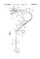
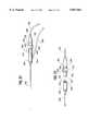
- FIG. 1is a side elevational view of an embodiment of a surgical instrument in accordance with the invention
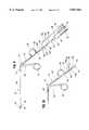
- FIG. 2is a side elevational view of a surgical tool of the surgical instrument of FIG. 1, including a shaft, handle, mounting tube and working element;
- FIG. 3is a top view of the surgical tool of FIG. 2;
- FIG. 4is an enlarged top view of a distal end of the surgical tool of FIGS. 2 and 3;
- FIG. 5is an enlarged end view of the distal end of the surgical tool of FIGS. 2-4;
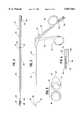
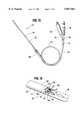
- FIG. 6is a side elevational view of an endoscope of the surgical instrument of FIG. 1;
- FIG. 7is an enlarged view of the endoscope of FIG. 6 taken near a distal end of a connector of the endoscope illustrating an irrigation channel defined in a proximal portion of the endoscope that terminates at the distal end of the connector;
- FIG. 8is a broken perspective view of the distal end of the surgical instrument of FIG. 1 illustrating with arrows an irrigation fluid passing from a distal end of a mounting tube;
- FIG. 9is a side elevational view of a further embodiment of the surgical instrument, illustrating an irrigation tube and a connector or luer assembly for securing an irrigation tube to a mounting tube and an endoscope and illustrating the luers in an aligned, but unengaged, position;
- FIG. 10is a broken side elevational view of the surgical instrument of FIG. 9, illustrating the luers in an engaged position;
- FIG. 11is a side elevational view of the endoscope of the surgical instrument of FIGS. 9 and 10 including one of the luers mounted to the endoscope;
- FIG. 12is a broken view of the irrigation tube assembly of the surgical instrument of FIGS. 9 and 10 including another one of the luers mounted to a distal end of the irrigation tube;
- FIG. 13is a broken side elevational view of the irrigation tube assembly of FIG. 12 and the endoscope of FIG. 11, illustrating the luer mounted on the distal end of the irrigation tube receivingly engaging a distal portion of the endoscope and illustrating with dashed lines a longitudinal channel defined by the luer of the irrigation tube assembly and a bore adapted to receive the luer of the endoscope;
- FIG. 14is a side elevational view of the surgical instrument in accordance with a still further embodiment of the invention, illustrating an irrigation tube assembly joined to a mounting tube by a branch fitting;
- FIG. 15is a side elevational view of an endoscope of the surgical instrument of FIG. 14 that does not include an irrigation channel;
- FIG. 16is a broken perspective view of a distal end of the surgical instrument illustrating a distal end of a mounting tube and an alternative embodiment of the endoscope defining an irrigation channel that terminates at its distal end and illustrating with arrows an irrigation fluid passing from the irrigation channel;
- FIG. 17is a side elevational view of a further embodiment of the surgical instrument, illustrating an alternative embodiment of a mount for mounting an endoscope to a shaft of the instrument in the form of a proximal mounting tube and a distal mounting tube;
- FIG. 18is a perspective view of a surgical scissors instrument in accordance with a further embodiment of the invention, with an enlarged view of a distal end of the instrument;
- FIG. 19is a side elevational view of a shaft and handle of the surgical instrument in accordance with a further embodiment of the invention.
- FIG. 20is a side elevational view of the surgical instrument in accordance with a further embodiment of the invention, including an alternative embodiment of an endoscope and a CCD camera head assembly removably secured to the endoscope;
- FIG. 21is a side elevation view of an endoscope and a CCD camera head assembly in accordance with an embodiment of the invention similar to the embodiment of FIG. 20;
- FIG. 22is a broken view illustrating the endoscope, the camera head assembly and means for securing together the endoscope and the CCD camera head assembly in accordance with the embodiment of FIG. 21.
- FIGS. 1-8A surgical instrument 10 in accordance with a preferred embodiment of the present invention is shown in FIGS. 1-8.
- the surgical instrument 10includes a tool 11 having an elongated shaft 12 with a handle 14 mounted on a proximal end 16 of the shaft, and a working element 18 mounted on a distal end 20 of the shaft.
- the surgical instrument 10also includes an optical assembly which preferably is in the form of a flexible endoscope 22.
- the handle 14has a portion that is intended to be gripped or held by a surgeon so that the working element can be used to manipulate tissue during a surgical procedure.
- the handle 14is offset relative to the shaft 12, and includes a first handle member 30 that is pivotally connected to a second handle member 32.
- the handle members 30 and 32terminate in respective finger receiving loops 34 and 36.
- the handle members 30 and 32 and the loops 34 and 36form the gripping portion of the handle 14.
- the endoscope 22extends from the handle gripping portion, such as either above the loop 36 or below the loop 36 as shown.
- the working element 18is rigidly secured to the distal end 20 of the shaft 12 in any suitable manner.
- the working element 18is in the form of forceps.
- the working element 18instead, however, may include a scissors (see FIGS. 18-19), knife, probe, or coagulator, electrosurgical electrodes, or any other suitable tool.
- the shaft 12may be in the form of a tube 40 with its proximal end fitted into a bore 42 defined in the second handle member 32 (see, e.g., FIG. 3).
- the shaft 12may be straight or have a predetermined bend or curve along its axis.
- the shaft 12may be rigid. It may be flexible, bendable or malleable so that it may be adjusted by the surgeon.
- the shaftmay have a distal portion that is displaceable to alternative positions wherein the distal portion does not have the same axis as a proximal portion of the shaft.
- the shaft 12may also include an actuating mechanism operably coupled to the working element 18 to operate the working element.
- An actuating rod or cablemay be affixed to the upper end of the first handle member 30 and extend through a lumen defined by the tube 40 to join the movable forceps 18.
- the shaft 12may be constructed of a stainless steel or any other suitable material.
- the flexible endoscope 22preferably includes at least one image fiber bundle 50 to permit viewing by a surgeon and one or more illumination fibers 52 (see, e.g., FIGS. 8 and 16).
- An objective lensis mounted on a distal end of the image fiber bundle 50 for defining a field of view which includes at least part of the working element 18, and to focus the light rays reflected from the illuminated surgical site onto the plane occupied by the distal end of the image fiber bundle.
- a mounting tube 60is affixed to the exterior of the shaft 12 and the handle 14, extending along substantially the entire length of the shaft 12 and handle 14 from a proximal end of the handle to near the working element 18.
- the mounting tube 60may be affixed to the shaft 12 and handle 14 in any suitable manner, such as, for example, by solder, welding or any suitable bonding agent.
- the mounting tube 60is illustrated as being affixed to the side or laterally of the shaft 12 relative to the handle 14.
- the mounting tube 60defines a longitudinal bore 62 extending between a proximal end 64 and a distal end 66 of the mounting tube. Alternatively, all or part of the mounting tube 60 and bore 62 may be defined by the handle 14 or shaft 12.
- the distal end 66 of the mounting tube 60may define a bulbous atraumatic tip 68 to enhance the tactile response of the instrument 10 and to eliminate sharp edges.
- the mounting tube 60may have a predetermined curve or bend to accommodate the offset handle 14 or any curves or bends in the shaft 12 or handle or so that the distal end of the endoscope 22 is positioned at a predetermined angle relative to the working element 18.
- the mounting tube 60may be rigid.
- the mounting tube 60may be bendable or malleable to accommodate a bendable or malleable shaft so that the surgical instrument 10 can be used to reach areas that may be difficult for the surgeon to reach.
- the bendable or malleable mounting tube 60also permits the surgeon to position the distal end of the endoscope 22 at a desired angle relative to the working element 18 and thereby adjust the viewing area of the endoscope.
- a malleable shaft 12 and tube 60is most preferred because it allows the surgeon to adjust the tool 11 to have a particular shape or bend and the chosen shape is retained.
- the mounting tubemay be constructed of any suitable material, such as, for example, stainless steel.
- a first connector 70is mounted at the proximal end 64 of the mounting tube 60, extending proximally of the handle 14, for removably securing the endoscope 22 to the mounting tube, as described below.
- the shaft 12 and mounting tube 60preferably are each adapted and constructed to have a small outside diameter such that the instrument 10 can be passed through an introducer, a cannula or directly into a narrow lumen or small surgical incision and still have a sufficient length to allow the working element 18 to reach the organ or tissue to be manipulated or cut.
- the outer diameters of the shaft 12 and the mounting tube 60are approximately 1.3 mm and 1.75 mm, respectively, and the distance between a distal end of the working element 18 and the proximal end 16 of the shaft is approximately 15 cm.
- the flexible endoscope 22includes a case or sheath 72 substantially along its length for encasing the image fiber bundle 50 and the illumination fibers 52.
- the sheath 72may be made of any suitable material that preferably is flexible such as, for example, a plastic or rubber tubing.
- the illumination fibers 52extend through a hub member 74 to an illumination fiber tube segment 94, and to a terminal connector 76 that is adapted to mate with a jack of suitable light source.
- the image fiber bundle 50passes through the hub member 74, to an image fiber bundle tube segment 96, and to a terminal connector 78 that is adapted to mate with an image input of a suitable viewing system or device such as a video unit or direct viewing optics.
- the endoscope 22includes a second connector 80 mounted on the endoscope proximal of the distal end of the endoscope.
- the second connector 80defines an endoscope working or distal portion 90 that extends distally of the second connector and a proximal portion 92 (see, e.g., FIGS. 6, 11 and 15).
- the distal portion 90 of the endoscope 22is inserted into the longitudinal bore 62 of the mounting tube 60 and slidingly receivable by the mounting tube until the second connector 80 comes into contact with the first connector 70.
- the two connectors 70 and 80are then matingly engaged, releasably locking the endoscope 22 and the mounting tube 60 together so that substantially the entire distal portion 90 of the endoscope extends within the longitudinal bore 62 of the mounting tube.
- the distal portion 90 of the endoscope 22 and the atraumatic bulbous tip 68are substantially co-terminus at their respective distal ends, or the distal end of the endoscope 22 is spaced proximally of the distal end of the atraumatic bulbous tip a predetermined distance.
- the first and second connectors 70 and 80may each be one part of a two-part fitting, such as luers or male and female SMA connectors (with, for example, the female part of the SMA connector mounted to the mounting tube and the male part of the SMA connector mounted on the endoscope 22).
- the distal portion 90 of the endoscope 22 and the mounting tube 60can be designed with very precise tolerances to correctly position the distal end of the endoscope 22 with respect to the working element 18.
- the distal portion 90 of the endoscope 22is slidably received within the mounting tube 60 and the endoscope is secured to the mounting tube only at the proximal end 64 of the mounting tube. Since the distal portion 90 of the endoscope 22 is not secured to the mounting tube along the length of the mounting tube 60, the mounting tube can be bent by the surgeon without causing undue stress to the endoscope which may damage or break the image fibers.
- the surgical instrument 10in accordance with a preferred embodiment of the invention desirably includes an irrigation means for providing an irrigation fluid to or near the distal end 66 of the mounting tube 60.
- the irrigation fluidis used to maintain a clear view through the endoscope 22.
- an irrigation passageway 120is defined within the longitudinal bore 62 of the mounting tube 60 by the distal portion 90 of the endoscope 22, through which the irrigation fluid is transferred.
- one or more apertures 121may be defined on the mounting tube 60 to provide additional outlets for the irrigation fluid and to relieve the fluid pressure of the irrigation fluid or tissue at the distal end 66 of the mounting tube 60.
- the inner diameter of the mounting tubeis approximately 1.5 mm and the outer diameter of the distal portion of the endoscope is approximately 1.0 mm.
- the irrigation passageway 120is particularly advantageous because it is adapted to transfer irrigation fluid along the shaft 12 of the surgical instrument 10 and outside the endoscope without adding to the size of the instrument.
- the irrigation means of this embodimentdoes not add structure along the length of the shaft because the passageway is defined within the mounting tube. Thus, the irrigation means does not interfere with the surgical procedure or significantly affect the control and tactile feel of the instrument.
- the irrigation passagewayalso facilitates re-useability of the endoscope.
- the irrigation passageway 120is in fluid flow communication with the irrigation fluid supply system by, for example, an irrigation channel 122 that is defined by the proximal portion 92 of the endoscope 22 (see FIG. 7).
- the irrigation channel 122extends within the proximal portion 92 of the endoscope, from a distal end of the second connector 80 and passes through a hub member 82, to an irrigation tube segment 84, and to an irrigation tube connector 86 that is attachable to an irrigation fluid supply system for providing the irrigation fluid.
- a segment 98 of the endoscope 22 that includes the image fiber bundle 50 and illumination fibers 52extends from the hub member 82 to the hub member 74.
- the irrigation channel 122may be defined by an irrigation tube contained within the proximal portion of the endoscope. As illustrated by the arrows in FIG. 8, the irrigation fluid passes through the longitudinal bore 62 between the mounting tube and the distal portion 90 of the endoscope 22.
- the endoscopeincludes a second sheath or case 126 that extends along the proximal portion 92 of the endoscope 22, terminating at or near the distal end of the second connector 80.
- the second sheath 126encases the sheath 72 and the irrigation channel 122 along the proximal portion of the endoscope 22.
- the irrigation channel 122runs from the hub member 82 to the distal end of the second connector 80 so that the irrigation fluid can pass from the irrigation channel to the irrigation passageway 120 when the first and second connectors 70 and 80 are mated (see, e.g., FIG. 7 and generally FIG. 1).
- An epoxycan be used to fill the space between the irrigation channel 122, the sheath 72 and the second sheath 126 within the proximal portion 92 of the endoscope 22.
- the irrigation passageway 120may be in fluid flow communication with the irrigation fluid supply system by a separate irrigation tube 132 that is not contained within the endoscope 22 and that is joined to the proximal end 64 of the mounting tube 60 in any suitable manner.
- the irrigation fluidalso passes through the longitudinal bore 62 between the mounting tube 60 and the endoscope 22.
- the irrigation tube 132is joined to the proximal end 64 of the mounting tube 60 by an assembly that includes three connectors, which preferably are in the form of three matingly-engageable luers.
- the irrigation tube 132extends proximally of the handle 14 to the irrigation tube connector 86.
- a center connector 140is joined to a distal end of the irrigation tube 132 that is matingly engageable with the first connector 70 on the mounting tube 60 and the second connector 80 on the endoscope 22.
- the center connector 140includes proximal and distal ends and defines a longitudinal channel 142 extending between the proximal and distal ends, with which the irrigation tube 132 is in fluid flow communication.
- the irrigation tube 132preferably has a slight bend near its distal end, and is joined to the center connector 140 approximately half way along the length of the center connector.
- the center connector 140defines a seat or bore 144 at its proximal end for receivingly engaging the second connector 80 and for providing a pressure fit.
- the longitudinal channel 142is adapted to receive the distal portion 90 of the endoscope 22 so that the center connector 140 can slidingly engage the distal portion 90 of the endoscope 22 prior to attachment of the connectors.
- the center connector 140can be slid along the distal portion 90 of the endoscope 22, and then engaged with the second connector 80 to attach together the irrigation tube 132 and the endoscope.
- the three connectors 70, 80, 140join together the irrigation tube 132, the mounting tube 60 and the endoscope 22 so that the irrigation fluid passes from the irrigation tube 132 to the longitudinal bore 62 of the mounting tube 60.
- a sealing relationshipis provided between the center connector 140 and the first and second connectors 70 and 80 so that all the irrigation fluid passes from the irrigation tube 132 to the irrigation passageway 120.
- the length of the center connectoris such that when the endoscope 22 is engaged with the surgical tool 11 the endoscope and the atraumatic bulbous tip 68 are substantially co-terminus at their respective distal ends, or the distal end of the endoscope 22 is spaced proximally of the distal end of the atraumatic bulbous tip a predetermined distance.
- the three connectors 70, 80, 140are illustrated in FIGS. 9-13 as being luers.
- the second and third luers or connectors 80, 140are joined together by a cylindrical lip 146 defined by a distal end of the second luer 80, which is adapted to be received snugly within the bore 144 of the third luer 140 and engage the third luer by a pressure fit.
- the third luer 140includes cylindrical lip 146 at its distal end that is adapted to be received within a bore defined in the first luer 70 and engage the first luer by a pressure fit.
- the luers 70, 80 and 140include a tapered portion 148 at their proximal ends to facilitate engagement.
- the center connector 140can be used without the first connector 70 or the second connector 80.
- the center connector 140may engage directly the mounting tube 160 or the endoscope by any suitable manner, such as, for example, a threading engagement.
- the connector assemblymay be used with surgical instruments that do not include a mounting tube, or that include an endoscope extending through the handle and shaft.
- a center connector 140 that is not mounted to an irrigation tubecan be used to engage the mounting tube with the endoscope.
- the first connector 70may include a branch fitting 160 mounted on the distal end of the irrigation tube 132 that is attachable to the center connector 140.
- the branch fitting 160extends from the mounting tube 60 for attachment to the center connector 140.
- the endoscope 22 of FIG. 15, which does not include an irrigation channel,may be used with the surgical tool 11 of FIG. 14.
- the endoscope 22may define an irrigation channel 110 that extends substantially the entire length of the endoscope 22 for providing the irrigation fluid to the distal end of the endoscope.
- the irrigation channel 110is encased by the sheath 72 and thus preferably is flexible.
- the irrigation channel 110may be defined by an irrigation tube contained within the endoscope.
- the irrigation channel 110passes through the hub member 82, to the irrigation tube segment 84, and to the irrigation tube connector 86 that is attachable to the irrigation fluid supply system for providing the irrigation fluid.
- the endoscope 22 containing an irrigation channel that extends all or part of the length of the endoscopeis generally intended to be disposable after a single use because the irrigation channel desirably has a relatively small diameter and thus is difficult to clean.
- the instrument 10includes a proximal mount 100 mounted to a proximal portion 102 of the shaft 12 and a distal mount 104 mounted to a distal portion 106 of the shaft 12.
- the proximal mount 100is also secured to the handle 14 and extends to the proximal end of the handle.
- the handle 14may be offset relative to the proximal portion 102 of the shaft 12. If desired, the proximal and distal portions 102 and 106 may be offset relative to each other. Because the endoscope 22 is flexible, it can be readily secured to the shaft 12 and the handle 14 if the handle is offset relative to the shaft or if the proximal and distal portions of the shaft are offset.
- the proximal and distal mounts 100 and 104are in the form of proximal and distal mounting tubes that define respective longitudinal bores 59 and 61 for receiving respective portions of the distal portion 90 of the endoscope 22.
- the first connector 70(which may be a luer or an SMA connector) may be secured to a proximal end of the proximal mount 100 for attachment to second connector 80 (which may be another luer or SMA connector) of the endoscope 22.
- a distal end of the distal mount 104may define the bulbous atraumatic tip 68 to enhance the tactile response of the instrument 10.
- the proximal and distal mounts 100 and 104may either be spaced or a continuous or unitary mount such as the tube 60 shown in FIGS. 1-3. Instead of mounting tubes, the proximal and distal mounts 100 and 104 may be in any other suitable form, such as, for example, a molded or shrinkable tubing adapted to form a secure compression fitting or shrinkable coupling, which is particularly useful for irregularly-shaped shafts.
- the tubingcan be heat, water or chemically shrinkable.
- a surgical tool 151 in accordance with another embodiment of the inventionis illustrated in the form of a scissors tool.
- the tool 151includes an elongated shaft 152 with a handle 154 mounted on a proximal end 156 of the shaft, and a working element in the form of a scissors 158 mounted on a distal end 159 of the shaft.
- a mounting tube 160is mounted to the exterior of the shaft 152 and handle 154, extending along substantially the entire length of the shaft and the handle.
- the mounting tube 160defines a longitudinal bore 162 extending between a proximal end 164 and a distal end 166 of the mounting tube for receiving a flexible endoscope.
- a first connector 170(such as a luer or an SMA connector) is mounted on the proximal end 164 of the mounting tube 160, extending proximally of the handle 154, for attachment to second connector 80 (such as another luer or an SMA connector) mounted along the length of the endoscope as describe above.
- the toolis designed so that the scissors-action can be imparted to the scissors 158 by squeezing together a pair of buttons 174 mounted on opposite sides of the shaft, in accordance with surgical scissors instruments known in the art.
- FIG. 19another alternative embodiment of the surgical instrument is illustrated that may be bendable or include a predetermined bend.
- the surgical instrumentincludes mounts 200 and 202 preferably on those portions of the shaft 12 that are not bent or do not flex.
- a working element 218 in the form of a scissorsis provided, and the mounts 200 and 202 are mounted respectively on the proximal and distal portions 102, 106 of the shaft 12.
- the mounts 200 and 202may be tubes molded or shrunk to respective portions of the shaft 12 to retain the endoscope 22. If desired, however, a bonding agent can be used.
- the mounts 200 and 202 and endoscope 22can be flexible to allow the endoscope 22 to be adjusted with the shaft 12, without interrupting or misaligning the view.
- the viewing systemmay, for example, include an eyepiece (not shown), which provides direct viewing of the image focused upon the distal end of the image fiber bundle by the objective lens.
- the imagemay also be fed to a video camera whose output is transmitted to a viewing screen or monitor for observation by the surgeon and the surgical support staff.
- one or more illumination fibers 52may be included as part of the same bundle as the image fiber bundle 50.
- the surgical instrument in accordance with the present inventioncan include more than one endoscope or optical assembly.
- the optical assemblymay, if desired, be a single image fiber bundle in the form of a rod lens, alone or in combination with a fiberoptic bundle.
- the rod lensmay be mounted on the shaft 12 and operably coupled to a flexible fiberoptic bundle having a plurality of image fiber bundles to provide a beneficial configuration of a small optical system on the operating portion of the instrument while still having the benefits of a flexible fiberoptic bundle extending from the handle 14.
- FIGS 20-22illustrate a surgical instrument 300 in accordance with alternative embodiments of the invention, including an endoscope 302 that is secured to a CCD camera head assembly 304 by, for example, a second connector 306 mounted on the endoscope.
- the endoscopemay be secured to the shaft by the second connector 306 and by the mounting tube 60 and the first connector 70 in accordance with the above-described embodiments.
- the CCD camera head assembly 304includes a casing 308, a CCD camera head 310, a CCD chip 312, and a focusing lens system 320 for focusing an image onto the CCD chip 312.
- the CCD camera head 310preferably has an outer diameter of about 1/4 inch (about 7 mm).
- the focusing lens system 320includes a focusing ring 322 and a lens 324, and a channel 326 is defined within the casing 308 to permit sliding of the lens 324 by the focusing ring 322 to bring the image into focus.
- An electric cord 330extends from the CCD camera head assembly 304 to a television monitor.
- a tubing 332extends from the second connector 306 that contains illumination fibers and, if desired, an irrigation tube.
- a proximal end of the second connector 306is removably secured to the CCD camera head assembly 304 preferably so that a distal end of an image fiber bundle 342 extending within the endoscope 302 is a predetermined distance from the CCD camera head 310 or the focusing lens 324 so that the image can readily be brought into focus.
- a first mating portion 344 having a male thread 346is defined at the proximal end of the second connector 306.
- a second mating portion 348 having a female threadis defined at a distal end of the casing 308 of the CCD camera head assembly 304. The first mating portion 344 is adapted to extend within the casing 308 and threadingly engage the second mating portion 348.
- FIGS. 20-22provides many advantages. For example, it enables the endoscope to be readily and easily secured adjacent the CCD camera head 310 so that the distal end of the image fiber bundle 342 and the focusing lens 324 or CCD camera head are spaced apart by a predetermined distance. Thus, the image can be readily and easily brought into focus. With this construction, the endoscope 302 can be disposable, with the camera head assembly 304 being reusable with other endoscopes. This is a significant advantage because CCD chips and camera heads tend to be relatively expensive components.
- the CCD camera head 310is positioned at a location that does not interfere with the surgical procedure and does not significantly affect the control and tactile feel of the instrument.
- the CCD camera headis sufficiently close to the surgical site, yet positioned so that it should not come into contact with the surgical site.
- the camera head assembly 304also preferably is compact and lightweight so that it does not add any significant bulk or weight to the surgical instrument. These embodiments also permit the CCD camera head to be heavily insulated by the casing 308 or other suitable insulation without interfering with the surgical procedure and without significantly affecting the control and tactile feel of the instrument.
- the present inventionalso includes a method of retro-fitting an existing surgical instrument with the endoscope 22.
- the methodstarts with an existing surgical tool 11 that includes the shaft 12 described above having proximal end 16 and distal end 20, the handle 14 connected to the proximal end of the shaft, and the working element 18 connected to the distal end of the shaft.
- the handle 14includes a gripping portion and is offset relative to the shaft.
- the flexible endoscope 22 described aboveis provided.
- the mounting tube 60 described aboveis secured to the shaft 12 so that the mounting tube extends along substantially the entire length of the shaft 12 and along the gripping portion.
- the endoscope 22is removably mounted to the shaft 12 by attaching the first and second connectors 70, 80 so that the distal portion 90 of the endoscope is received within the mounting tube 60 and extends along substantially the entire length of the shaft 12 and along the gripping portion and so that a distal end of the endoscope can be used to view the working element.
- the reference gaugeincludes at least two steps, one for the end of the tool 11 and one for the distal end of the endoscope 22 while the endoscope is being mounted to the shaft 12.
Landscapes
- Health & Medical Sciences (AREA)
- Life Sciences & Earth Sciences (AREA)
- Surgery (AREA)
- Animal Behavior & Ethology (AREA)
- Public Health (AREA)
- Engineering & Computer Science (AREA)
- Biomedical Technology (AREA)
- Heart & Thoracic Surgery (AREA)
- Medical Informatics (AREA)
- Molecular Biology (AREA)
- Optics & Photonics (AREA)
- General Health & Medical Sciences (AREA)
- Nuclear Medicine, Radiotherapy & Molecular Imaging (AREA)
- Veterinary Medicine (AREA)
- Physics & Mathematics (AREA)
- Biophysics (AREA)
- Pathology (AREA)
- Radiology & Medical Imaging (AREA)
- Ophthalmology & Optometry (AREA)
- Surgical Instruments (AREA)
- Endoscopes (AREA)
Abstract
Description
Claims (59)
Priority Applications (3)
| Application Number | Priority Date | Filing Date | Title |
|---|---|---|---|
| US08/596,073US5857961A (en) | 1995-06-07 | 1996-02-06 | Surgical instrument for use with a viewing system |
| PCT/US1996/009269WO1996039915A1 (en) | 1995-06-07 | 1996-06-06 | Surgical instrument for use with a viewing system |
| EP96918245AEP0836405A4 (en) | 1995-06-07 | 1996-06-06 | Surgical instrument for use with a viewing system |
Applications Claiming Priority (2)
| Application Number | Priority Date | Filing Date | Title |
|---|---|---|---|
| US08/472,187US5667473A (en) | 1994-03-18 | 1995-06-07 | Surgical instrument and method for use with a viewing system |
| US08/596,073US5857961A (en) | 1995-06-07 | 1996-02-06 | Surgical instrument for use with a viewing system |
Related Parent Applications (1)
| Application Number | Title | Priority Date | Filing Date |
|---|---|---|---|
| US08/472,187Continuation-In-PartUS5667473A (en) | 1994-03-18 | 1995-06-07 | Surgical instrument and method for use with a viewing system |
Publications (1)
| Publication Number | Publication Date |
|---|---|
| US5857961Atrue US5857961A (en) | 1999-01-12 |
Family
ID=27043685
Family Applications (1)
| Application Number | Title | Priority Date | Filing Date |
|---|---|---|---|
| US08/596,073Expired - LifetimeUS5857961A (en) | 1995-06-07 | 1996-02-06 | Surgical instrument for use with a viewing system |
Country Status (3)
| Country | Link |
|---|---|
| US (1) | US5857961A (en) |
| EP (1) | EP0836405A4 (en) |
| WO (1) | WO1996039915A1 (en) |
Cited By (55)
| Publication number | Priority date | Publication date | Assignee | Title |
|---|---|---|---|---|
| US6066102A (en)* | 1998-03-09 | 2000-05-23 | Spectrascience, Inc. | Optical biopsy forceps system and method of diagnosing tissue |
| US6129683A (en)* | 1996-05-07 | 2000-10-10 | Spectrascience, Inc. | Optical biopsy forceps |
| US20020173786A1 (en)* | 2001-05-21 | 2002-11-21 | Kortenbach Juergen A. | Methods and apparatus for on-endoscope instruments having end effectors and combinations of on-endoscope and through-endoscope instruments |
| US20030055314A1 (en)* | 1993-11-23 | 2003-03-20 | Tony Petitto | Technique for depth of field viewing of images using an endoscopic instrument |
| US20030078476A1 (en)* | 2001-07-24 | 2003-04-24 | Hill Stephen D. | Apparatus for intubation |
| US20030233092A1 (en)* | 2000-12-06 | 2003-12-18 | Kortenbach Juergen A. | Methods and apparatus for the treatment of gastric ulcers |
| US6685716B1 (en)* | 2000-01-04 | 2004-02-03 | Transvascular, Inc. | Over-the-wire apparatus and method for open surgery making of fluid connection between two neighboring vessels |
| US6749605B2 (en) | 1996-10-23 | 2004-06-15 | Oratec Interventions, Inc. | Catheter for delivery of energy to a surgical site |
| US6752756B2 (en) | 1998-06-22 | 2004-06-22 | Origin Medsystems, Inc. | Combined vessel dissection and transection device and method |
| US6830546B1 (en) | 1998-06-22 | 2004-12-14 | Origin Medsystems, Inc. | Device and method for remote vessel ligation |
| US20050250983A1 (en)* | 2004-04-16 | 2005-11-10 | Anthony Tremaglio | Endoscopic instrument having reduced diameter flexible shaft |
| US6976957B1 (en)* | 1998-06-22 | 2005-12-20 | Origin Medsystems, Inc. | Cannula-based surgical instrument and method |
| US20060052660A1 (en)* | 1999-08-10 | 2006-03-09 | Chin Albert K | Apparatus and methods for cardiac restraint |
| US20060116746A1 (en)* | 2003-01-17 | 2006-06-01 | Chin Albert K | Cardiac electrode attachment procedure |
| US20060293561A1 (en)* | 2005-06-24 | 2006-12-28 | Abay Eustaquio O Ii | System and methods for intervertebral disc surgery |
| US20070182842A1 (en)* | 2004-05-31 | 2007-08-09 | Medigus Ltd. | Reusable miniature camera head |
| US7326178B1 (en) | 1998-06-22 | 2008-02-05 | Origin Medsystems, Inc. | Vessel retraction device and method |
| US20080045859A1 (en)* | 2006-08-19 | 2008-02-21 | Fritsch Michael H | Devices and Methods for In-Vivo Pathology Diagnosis |
| US20080287742A1 (en)* | 2007-04-17 | 2008-11-20 | Gyrus Acmi, Inc. | Light source power based on predetermined sensed condition |
| US20080306333A1 (en)* | 1999-08-10 | 2008-12-11 | Chin Albert K | Apparatus and Method for Endoscopic Surgical Procedures |
| US20090024156A1 (en)* | 1995-07-13 | 2009-01-22 | Chin Albert K | Tissue Dissection Method |
| US20090131907A1 (en)* | 1999-08-10 | 2009-05-21 | Maquet Cardiovascular Llc | Endoscopic Cardiac Surgery |
| US20090149716A1 (en)* | 2007-12-07 | 2009-06-11 | Socorro Medical, Inc. | Endoscopic system for accessing constrained surgical spaces |
| US20100121142A1 (en)* | 2008-11-12 | 2010-05-13 | Ouyang Xiaolong | Minimally Invasive Imaging Device |
| US20100121139A1 (en)* | 2008-11-12 | 2010-05-13 | Ouyang Xiaolong | Minimally Invasive Imaging Systems |
| US20100121155A1 (en)* | 2008-11-12 | 2010-05-13 | Ouyang Xiaolong | Minimally Invasive Tissue Modification Systems With Integrated Visualization |
| US20100286477A1 (en)* | 2009-05-08 | 2010-11-11 | Ouyang Xiaolong | Internal tissue visualization system comprising a rf-shielded visualization sensor module |
| US20100331856A1 (en)* | 2008-12-12 | 2010-12-30 | Hansen Medical Inc. | Multiple flexible and steerable elongate instruments for minimally invasive operations |
| US20110060184A1 (en)* | 2009-09-08 | 2011-03-10 | Gyrus Acmi, Inc. | Endoscopic illumination system, assembly and methods for staged illumination of different target areas |
| US7938842B1 (en) | 1998-08-12 | 2011-05-10 | Maquet Cardiovascular Llc | Tissue dissector apparatus |
| US20140039324A1 (en)* | 2005-01-21 | 2014-02-06 | Giovanni Speziali | Thorascopic Heart Valve Repair Method and Apparatus |
| US9211059B2 (en) | 2007-06-19 | 2015-12-15 | Minimally Invasive Devices, Inc. | Systems and methods for optimizing and maintaining visualization of a surgical field during the use of surgical scopes |
| US20160106300A1 (en)* | 2014-10-17 | 2016-04-21 | Willard S. Noyes | Flexible Endoscopic Exoskeleton Surgical System |
| US9370295B2 (en) | 2014-01-13 | 2016-06-21 | Trice Medical, Inc. | Fully integrated, disposable tissue visualization device |
| WO2016177600A1 (en)* | 2015-05-06 | 2016-11-10 | Koninklijke Philips N.V. | Optical tissue feedback device for an electrosurgical device |
| US9522017B2 (en) | 2010-12-03 | 2016-12-20 | Minimally Invasive Devices, Inc. | Devices, systems, and methods for performing endoscopic surgical procedures |
| US9603510B2 (en) | 2011-05-17 | 2017-03-28 | Mario Ammirati | Method and apparatus for delivering an endoscope via microsurgical instruments while performing microscopic surgery |
| US10231609B2 (en) | 2007-06-19 | 2019-03-19 | Floshield, Inc. | Systems and methods for optimizing and maintaining visualization of a surgical field during the use of surgical scopes |
| US10299770B2 (en) | 2006-06-01 | 2019-05-28 | Maquet Cardiovascular Llc | Endoscopic vessel harvesting system components |
| US10342579B2 (en) | 2014-01-13 | 2019-07-09 | Trice Medical, Inc. | Fully integrated, disposable tissue visualization device |
| US10398292B2 (en) | 2013-03-14 | 2019-09-03 | Floshield, Inc. | Fluid dispensing control systems and methods |
| US10398290B2 (en) | 2007-06-19 | 2019-09-03 | Floshield, Inc. | Device for maintaining visualization with surgical scopes |
| US10405886B2 (en) | 2015-08-11 | 2019-09-10 | Trice Medical, Inc. | Fully integrated, disposable tissue visualization device |
| US10507012B2 (en) | 2000-11-17 | 2019-12-17 | Maquet Cardiovascular Llc | Vein harvesting system and method |
| US10507018B2 (en) | 2007-10-18 | 2019-12-17 | Neochord, Inc. | Minimally invasive repair of a valve leaflet in a beating heart |
| US10588620B2 (en) | 2018-03-23 | 2020-03-17 | Neochord, Inc. | Device for suture attachment for minimally invasive heart valve repair |
| US10966709B2 (en) | 2018-09-07 | 2021-04-06 | Neochord, Inc. | Device for suture attachment for minimally invasive heart valve repair |
| US11096569B2 (en)* | 2014-10-15 | 2021-08-24 | Covidien Lp | Endoscope with a multiple diameter working section |
| US11173030B2 (en) | 2018-05-09 | 2021-11-16 | Neochord, Inc. | Suture length adjustment for minimally invasive heart valve repair |
| US11253360B2 (en) | 2018-05-09 | 2022-02-22 | Neochord, Inc. | Low profile tissue anchor for minimally invasive heart valve repair |
| US11376126B2 (en) | 2019-04-16 | 2022-07-05 | Neochord, Inc. | Transverse helical cardiac anchor for minimally invasive heart valve repair |
| US11547446B2 (en) | 2014-01-13 | 2023-01-10 | Trice Medical, Inc. | Fully integrated, disposable tissue visualization device |
| US11589989B2 (en) | 2017-03-31 | 2023-02-28 | Neochord, Inc. | Minimally invasive heart valve repair in a beating heart |
| US11622753B2 (en) | 2018-03-29 | 2023-04-11 | Trice Medical, Inc. | Fully integrated endoscope with biopsy capabilities and methods of use |
| US12208007B2 (en) | 2020-01-16 | 2025-01-28 | Neochord, Inc. | Helical cardiac anchors for minimally invasive heart valve repair |
Families Citing this family (3)
| Publication number | Priority date | Publication date | Assignee | Title |
|---|---|---|---|---|
| DE19910295C2 (en) | 1999-03-09 | 2002-06-20 | Storz Karl Gmbh & Co Kg | Medical or technical endoscopic instrument |
| ES2294919B1 (en) | 2006-03-07 | 2009-02-16 | Consejo Superior Investig. Cientificas | CONTINUOUS OVEN WITH COUPLED LASER FOR SURFACE TREATMENT OF MATERIALS. |
| EP2221005B1 (en)* | 2009-02-18 | 2014-11-19 | University Of Dundee | Endoscopic retractor |
Citations (36)
| Publication number | Priority date | Publication date | Assignee | Title |
|---|---|---|---|---|
| US2068721A (en)* | 1932-11-18 | 1937-01-26 | Wappler Frederick Charles | Method for electrosurgical severance of adhesions |
| US2691370A (en)* | 1952-03-27 | 1954-10-12 | American Cystoscope Makers Inc | Instrument for heart surgery |
| DE2024195A1 (en)* | 1969-05-19 | 1970-11-26 | Vicon Products Corp., Mamaroneck, N.Y. (V.St.A.) | Device for transmitting light |
| US3664330A (en)* | 1969-09-12 | 1972-05-23 | Harold L Deutsch | Fiber optic medical tool |
| US3882854A (en)* | 1973-08-23 | 1975-05-13 | Research Corp | Surgical clip and applicator |
| US4300564A (en)* | 1978-11-09 | 1981-11-17 | Olympus Optical Co., Ltd. | Forceps for extracting stones in the pelvis of a kidney |
| US4471766A (en)* | 1977-11-24 | 1984-09-18 | Inbae Yoon | Ring applicator with an endoscope |
| DE8600868U1 (en)* | 1986-01-16 | 1986-03-06 | Dausch, Hermann, 78532 Tuttlingen | Microsurgical forceps |
| US4576145A (en)* | 1983-02-22 | 1986-03-18 | Sumitomo Electric Industries, Ltd. | Fiberscope |
| US4588294A (en)* | 1984-06-27 | 1986-05-13 | Warner-Lambert Technologies, Inc. | Searching and measuring endoscope |
| US4616631A (en)* | 1979-02-10 | 1986-10-14 | Kabushiki Kaisha Medos Kenkyusho | Flexible pipe assembly for endoscope |
| US4620547A (en)* | 1983-12-31 | 1986-11-04 | Richard Wolf Gmbh | Instrument for sampling tissue specimens |
| US4651201A (en)* | 1984-06-01 | 1987-03-17 | Arnold Schoolman | Stereoscopic endoscope arrangement |
| US4656999A (en)* | 1984-01-30 | 1987-04-14 | Karl Storz | Contact endoscope |
| US4759348A (en)* | 1981-09-28 | 1988-07-26 | Cawood Charles David | Endoscope assembly and surgical instrument for use therewith |
| US4770163A (en)* | 1982-12-15 | 1988-09-13 | Sumitomo Electric Industries, Ltd. | Fiberscope |
| US4782819A (en)* | 1987-02-25 | 1988-11-08 | Adair Edwin Lloyd | Optical catheter |
| EP0316816A1 (en)* | 1987-11-13 | 1989-05-24 | Hannes Dr. Haberl | Surgical forceps |
| US4867529A (en)* | 1987-05-09 | 1989-09-19 | Mitsubishi Cable Industries, Ltd. | Super-thin fiberscope |
| DE3920706A1 (en)* | 1989-06-24 | 1991-01-10 | Foerster Ernst | Catheter for carrying out a biopsy - has mini-endoscope and a forceps combined with an inner sheath which slides in an outer sheath |
| US5016098A (en)* | 1987-03-05 | 1991-05-14 | Fuji Optical Systems, Incorporated | Electronic video dental camera |
| WO1992007857A1 (en)* | 1990-10-26 | 1992-05-14 | Schering Aktiengesellschaft Berlin Und Bergkamen | Epoxycarbacyclin precursors, their preparation and their use |
| WO1992009616A1 (en)* | 1990-12-03 | 1992-06-11 | THE UNITED OF AMERICA, represented by THE SECRETARY, UNITED STATES DEPARTMENT OF COMMERCE | Enhancement of musculature in animals |
| WO1992009564A1 (en)* | 1990-12-03 | 1992-06-11 | Celltech Limited | Peptidyl derivatives |
| US5127393A (en)* | 1991-05-28 | 1992-07-07 | Medilase, Inc. | Flexible endoscope with rigid introducer |
| US5147356A (en)* | 1991-04-16 | 1992-09-15 | Microsurge, Inc. | Surgical instrument |
| US5152779A (en)* | 1989-08-11 | 1992-10-06 | Olympus Optical Co., Ltd. | Forceps instrument |
| US5197457A (en)* | 1990-09-12 | 1993-03-30 | Adair Edwin Lloyd | Deformable and removable sheath for optical catheter |
| US5230621A (en)* | 1991-12-26 | 1993-07-27 | Bennett Jacoby | Endoscopic method and device for subgingival dental procedures |
| US5263928A (en)* | 1991-06-14 | 1993-11-23 | Baxter International Inc. | Catheter and endoscope assembly and method of use |
| US5281134A (en)* | 1991-11-19 | 1994-01-25 | Schultz Allen J | Fiber optic illumination system for dental instruments |
| US5312400A (en)* | 1992-10-09 | 1994-05-17 | Symbiosis Corporation | Cautery probes for endoscopic electrosurgical suction-irrigation instrument |
| WO1994014368A1 (en)* | 1992-12-18 | 1994-07-07 | Gennaro Di Fazio | A visualization device with optic fibres that may be applied to a laryngoscope |
| US5373840A (en)* | 1992-10-02 | 1994-12-20 | Knighton; David R. | Endoscope and method for vein removal |
| US5512034A (en)* | 1992-11-25 | 1996-04-30 | Finn; Miles A. | Surgical instrument including viewing optics and a ball probe |
| US5667472A (en)* | 1994-03-18 | 1997-09-16 | Clarus Medical Systems, Inc. | Surgical instrument and method for use with a viewing system |
- 1996
- 1996-02-06USUS08/596,073patent/US5857961A/ennot_activeExpired - Lifetime
- 1996-06-06EPEP96918245Apatent/EP0836405A4/ennot_activeWithdrawn
- 1996-06-06WOPCT/US1996/009269patent/WO1996039915A1/ennot_activeApplication Discontinuation
Patent Citations (37)
| Publication number | Priority date | Publication date | Assignee | Title |
|---|---|---|---|---|
| US2068721A (en)* | 1932-11-18 | 1937-01-26 | Wappler Frederick Charles | Method for electrosurgical severance of adhesions |
| US2691370A (en)* | 1952-03-27 | 1954-10-12 | American Cystoscope Makers Inc | Instrument for heart surgery |
| DE2024195A1 (en)* | 1969-05-19 | 1970-11-26 | Vicon Products Corp., Mamaroneck, N.Y. (V.St.A.) | Device for transmitting light |
| US3664330A (en)* | 1969-09-12 | 1972-05-23 | Harold L Deutsch | Fiber optic medical tool |
| US3882854A (en)* | 1973-08-23 | 1975-05-13 | Research Corp | Surgical clip and applicator |
| US4471766A (en)* | 1977-11-24 | 1984-09-18 | Inbae Yoon | Ring applicator with an endoscope |
| US4300564A (en)* | 1978-11-09 | 1981-11-17 | Olympus Optical Co., Ltd. | Forceps for extracting stones in the pelvis of a kidney |
| US4616631A (en)* | 1979-02-10 | 1986-10-14 | Kabushiki Kaisha Medos Kenkyusho | Flexible pipe assembly for endoscope |
| US4759348A (en)* | 1981-09-28 | 1988-07-26 | Cawood Charles David | Endoscope assembly and surgical instrument for use therewith |
| US4770163A (en)* | 1982-12-15 | 1988-09-13 | Sumitomo Electric Industries, Ltd. | Fiberscope |
| US4576145A (en)* | 1983-02-22 | 1986-03-18 | Sumitomo Electric Industries, Ltd. | Fiberscope |
| US4620547A (en)* | 1983-12-31 | 1986-11-04 | Richard Wolf Gmbh | Instrument for sampling tissue specimens |
| US4656999A (en)* | 1984-01-30 | 1987-04-14 | Karl Storz | Contact endoscope |
| US4651201A (en)* | 1984-06-01 | 1987-03-17 | Arnold Schoolman | Stereoscopic endoscope arrangement |
| US4588294A (en)* | 1984-06-27 | 1986-05-13 | Warner-Lambert Technologies, Inc. | Searching and measuring endoscope |
| DE8600868U1 (en)* | 1986-01-16 | 1986-03-06 | Dausch, Hermann, 78532 Tuttlingen | Microsurgical forceps |
| US4782819A (en)* | 1987-02-25 | 1988-11-08 | Adair Edwin Lloyd | Optical catheter |
| US5016098A (en)* | 1987-03-05 | 1991-05-14 | Fuji Optical Systems, Incorporated | Electronic video dental camera |
| US4867529A (en)* | 1987-05-09 | 1989-09-19 | Mitsubishi Cable Industries, Ltd. | Super-thin fiberscope |
| EP0316816A1 (en)* | 1987-11-13 | 1989-05-24 | Hannes Dr. Haberl | Surgical forceps |
| DE3920706A1 (en)* | 1989-06-24 | 1991-01-10 | Foerster Ernst | Catheter for carrying out a biopsy - has mini-endoscope and a forceps combined with an inner sheath which slides in an outer sheath |
| US5152779A (en)* | 1989-08-11 | 1992-10-06 | Olympus Optical Co., Ltd. | Forceps instrument |
| US5197457A (en)* | 1990-09-12 | 1993-03-30 | Adair Edwin Lloyd | Deformable and removable sheath for optical catheter |
| WO1992007857A1 (en)* | 1990-10-26 | 1992-05-14 | Schering Aktiengesellschaft Berlin Und Bergkamen | Epoxycarbacyclin precursors, their preparation and their use |
| WO1992009564A1 (en)* | 1990-12-03 | 1992-06-11 | Celltech Limited | Peptidyl derivatives |
| WO1992009616A1 (en)* | 1990-12-03 | 1992-06-11 | THE UNITED OF AMERICA, represented by THE SECRETARY, UNITED STATES DEPARTMENT OF COMMERCE | Enhancement of musculature in animals |
| US5147356A (en)* | 1991-04-16 | 1992-09-15 | Microsurge, Inc. | Surgical instrument |
| US5127393A (en)* | 1991-05-28 | 1992-07-07 | Medilase, Inc. | Flexible endoscope with rigid introducer |
| US5263928A (en)* | 1991-06-14 | 1993-11-23 | Baxter International Inc. | Catheter and endoscope assembly and method of use |
| US5281134A (en)* | 1991-11-19 | 1994-01-25 | Schultz Allen J | Fiber optic illumination system for dental instruments |
| US5230621A (en)* | 1991-12-26 | 1993-07-27 | Bennett Jacoby | Endoscopic method and device for subgingival dental procedures |
| US5373840A (en)* | 1992-10-02 | 1994-12-20 | Knighton; David R. | Endoscope and method for vein removal |
| US5312400A (en)* | 1992-10-09 | 1994-05-17 | Symbiosis Corporation | Cautery probes for endoscopic electrosurgical suction-irrigation instrument |
| US5512034A (en)* | 1992-11-25 | 1996-04-30 | Finn; Miles A. | Surgical instrument including viewing optics and a ball probe |
| WO1994014368A1 (en)* | 1992-12-18 | 1994-07-07 | Gennaro Di Fazio | A visualization device with optic fibres that may be applied to a laryngoscope |
| US5667472A (en)* | 1994-03-18 | 1997-09-16 | Clarus Medical Systems, Inc. | Surgical instrument and method for use with a viewing system |
| US5667473A (en)* | 1994-03-18 | 1997-09-16 | Clarus Medical Systems, Inc. | Surgical instrument and method for use with a viewing system |
Non-Patent Citations (2)
| Title |
|---|
| "Fourth Annual Course On Minimally Invasive Therapy Of The Brain", dated Aug. 25-27, 1994, and presented at Loew's Hotel in Santa Monica, California. |
| Fourth Annual Course On Minimally Invasive Therapy Of The Brain , dated Aug. 25 27, 1994, and presented at Loew s Hotel in Santa Monica, California.* |
Cited By (98)
| Publication number | Priority date | Publication date | Assignee | Title |
|---|---|---|---|---|
| US20030055314A1 (en)* | 1993-11-23 | 2003-03-20 | Tony Petitto | Technique for depth of field viewing of images using an endoscopic instrument |
| US20090024156A1 (en)* | 1995-07-13 | 2009-01-22 | Chin Albert K | Tissue Dissection Method |
| US7981133B2 (en) | 1995-07-13 | 2011-07-19 | Maquet Cardiovascular, Llc | Tissue dissection method |
| US6129683A (en)* | 1996-05-07 | 2000-10-10 | Spectrascience, Inc. | Optical biopsy forceps |
| US6749605B2 (en) | 1996-10-23 | 2004-06-15 | Oratec Interventions, Inc. | Catheter for delivery of energy to a surgical site |
| US7309336B2 (en) | 1996-10-23 | 2007-12-18 | Oratec Interventions, Inc. | Catheter for delivery of energy to a surgical site |
| US6394964B1 (en) | 1998-03-09 | 2002-05-28 | Spectrascience, Inc. | Optical forceps system and method of diagnosing and treating tissue |
| US6066102A (en)* | 1998-03-09 | 2000-05-23 | Spectrascience, Inc. | Optical biopsy forceps system and method of diagnosing tissue |
| US20090131747A1 (en)* | 1998-06-22 | 2009-05-21 | Maquet Cardiovascular Llc | Instrument And Method For Remotely Manipulating A Tissue Structure |
| US7972265B1 (en) | 1998-06-22 | 2011-07-05 | Maquet Cardiovascular, Llc | Device and method for remote vessel ligation |
| US7867163B2 (en) | 1998-06-22 | 2011-01-11 | Maquet Cardiovascular Llc | Instrument and method for remotely manipulating a tissue structure |
| US6830546B1 (en) | 1998-06-22 | 2004-12-14 | Origin Medsystems, Inc. | Device and method for remote vessel ligation |
| US6752756B2 (en) | 1998-06-22 | 2004-06-22 | Origin Medsystems, Inc. | Combined vessel dissection and transection device and method |
| US8241210B2 (en) | 1998-06-22 | 2012-08-14 | Maquet Cardiovascular Llc | Vessel retractor |
| US6976957B1 (en)* | 1998-06-22 | 2005-12-20 | Origin Medsystems, Inc. | Cannula-based surgical instrument and method |
| US7476198B1 (en) | 1998-06-22 | 2009-01-13 | Maquet Cardiovascular, Llc | Cannula-based surgical instrument |
| US7326178B1 (en) | 1998-06-22 | 2008-02-05 | Origin Medsystems, Inc. | Vessel retraction device and method |
| US7938842B1 (en) | 1998-08-12 | 2011-05-10 | Maquet Cardiovascular Llc | Tissue dissector apparatus |
| US9700398B2 (en) | 1998-08-12 | 2017-07-11 | Maquet Cardiovascular Llc | Vessel harvester |
| US9730782B2 (en) | 1998-08-12 | 2017-08-15 | Maquet Cardiovascular Llc | Vessel harvester |
| US8460331B2 (en) | 1998-08-12 | 2013-06-11 | Maquet Cardiovascular, Llc | Tissue dissector apparatus and method |
| US8986335B2 (en) | 1998-08-12 | 2015-03-24 | Maquet Cardiovascular Llc | Tissue dissector apparatus and method |
| US20080306333A1 (en)* | 1999-08-10 | 2008-12-11 | Chin Albert K | Apparatus and Method for Endoscopic Surgical Procedures |
| US20060052660A1 (en)* | 1999-08-10 | 2006-03-09 | Chin Albert K | Apparatus and methods for cardiac restraint |
| US20090131907A1 (en)* | 1999-08-10 | 2009-05-21 | Maquet Cardiovascular Llc | Endoscopic Cardiac Surgery |
| US6685716B1 (en)* | 2000-01-04 | 2004-02-03 | Transvascular, Inc. | Over-the-wire apparatus and method for open surgery making of fluid connection between two neighboring vessels |
| US10507012B2 (en) | 2000-11-17 | 2019-12-17 | Maquet Cardiovascular Llc | Vein harvesting system and method |
| US7083617B2 (en)* | 2000-12-06 | 2006-08-01 | Syntheon, Llc | Methods and apparatus for the treatment of gastric ulcers |
| US20030233092A1 (en)* | 2000-12-06 | 2003-12-18 | Kortenbach Juergen A. | Methods and apparatus for the treatment of gastric ulcers |
| US6808491B2 (en)* | 2001-05-21 | 2004-10-26 | Syntheon, Llc | Methods and apparatus for on-endoscope instruments having end effectors and combinations of on-endoscope and through-endoscope instruments |
| US20020173786A1 (en)* | 2001-05-21 | 2002-11-21 | Kortenbach Juergen A. | Methods and apparatus for on-endoscope instruments having end effectors and combinations of on-endoscope and through-endoscope instruments |
| US6929600B2 (en) | 2001-07-24 | 2005-08-16 | Stephen D. Hill | Apparatus for intubation |
| US20030078476A1 (en)* | 2001-07-24 | 2003-04-24 | Hill Stephen D. | Apparatus for intubation |
| US20060116746A1 (en)* | 2003-01-17 | 2006-06-01 | Chin Albert K | Cardiac electrode attachment procedure |
| US8517921B2 (en) | 2004-04-16 | 2013-08-27 | Gyrus Acmi, Inc. | Endoscopic instrument having reduced diameter flexible shaft |
| US20050250983A1 (en)* | 2004-04-16 | 2005-11-10 | Anthony Tremaglio | Endoscopic instrument having reduced diameter flexible shaft |
| US20070182842A1 (en)* | 2004-05-31 | 2007-08-09 | Medigus Ltd. | Reusable miniature camera head |
| US10582924B2 (en) | 2005-01-21 | 2020-03-10 | Mayo Foundation For Medical Education And Research | Thorascopic heart valve repair method |
| US9700300B2 (en) | 2005-01-21 | 2017-07-11 | Mayo Foundation For Medical Education And Research | Thorascopic heart valve repair apparatus |
| US11534156B2 (en) | 2005-01-21 | 2022-12-27 | Mayo Foundation For Medical Education And Research | Thorascopic heart valve repair method and apparatus |
| US20140039324A1 (en)* | 2005-01-21 | 2014-02-06 | Giovanni Speziali | Thorascopic Heart Valve Repair Method and Apparatus |
| US9364213B2 (en)* | 2005-01-21 | 2016-06-14 | Mayo Foundation For Medical Education And Research | Thorascopic heart valve repair method |
| US20060293561A1 (en)* | 2005-06-24 | 2006-12-28 | Abay Eustaquio O Ii | System and methods for intervertebral disc surgery |
| US10299770B2 (en) | 2006-06-01 | 2019-05-28 | Maquet Cardiovascular Llc | Endoscopic vessel harvesting system components |
| US11134835B2 (en) | 2006-06-01 | 2021-10-05 | Maquet Cardiovascular Llc | Endoscopic vessel harvesting system components |
| US11141055B2 (en) | 2006-06-01 | 2021-10-12 | Maquet Cardiovascular Llc | Endoscopic vessel harvesting system components |
| US20080045859A1 (en)* | 2006-08-19 | 2008-02-21 | Fritsch Michael H | Devices and Methods for In-Vivo Pathology Diagnosis |
| US8926503B2 (en) | 2007-04-17 | 2015-01-06 | Gyrus Acmi, Inc. | Light source power based on predetermined sensed condition |
| US20080287742A1 (en)* | 2007-04-17 | 2008-11-20 | Gyrus Acmi, Inc. | Light source power based on predetermined sensed condition |
| US8591408B2 (en) | 2007-04-17 | 2013-11-26 | Gyrus Acmi, Inc. | Light source power based on predetermined sensed condition |
| US8372003B2 (en) | 2007-04-17 | 2013-02-12 | Gyrus Acmi, Inc. | Light source power based on predetermined sensed condition |
| US10398290B2 (en) | 2007-06-19 | 2019-09-03 | Floshield, Inc. | Device for maintaining visualization with surgical scopes |
| US9211059B2 (en) | 2007-06-19 | 2015-12-15 | Minimally Invasive Devices, Inc. | Systems and methods for optimizing and maintaining visualization of a surgical field during the use of surgical scopes |
| US10231609B2 (en) | 2007-06-19 | 2019-03-19 | Floshield, Inc. | Systems and methods for optimizing and maintaining visualization of a surgical field during the use of surgical scopes |
| US12426874B2 (en) | 2007-10-18 | 2025-09-30 | Neochord, Inc. | Minimally invasive repair of a valve leaflet in a beating heart |
| US10507018B2 (en) | 2007-10-18 | 2019-12-17 | Neochord, Inc. | Minimally invasive repair of a valve leaflet in a beating heart |
| US9050004B2 (en) | 2007-12-07 | 2015-06-09 | Socorro Medical, Inc. | Endoscopic system for accessing constrained surgical spaces |
| US20090149716A1 (en)* | 2007-12-07 | 2009-06-11 | Socorro Medical, Inc. | Endoscopic system for accessing constrained surgical spaces |
| US10085733B2 (en) | 2007-12-07 | 2018-10-02 | Socorro Medical, Inc. | Endoscopic system for accessing constrained surgical spaces |
| US20100121142A1 (en)* | 2008-11-12 | 2010-05-13 | Ouyang Xiaolong | Minimally Invasive Imaging Device |
| US20100121155A1 (en)* | 2008-11-12 | 2010-05-13 | Ouyang Xiaolong | Minimally Invasive Tissue Modification Systems With Integrated Visualization |
| US10045686B2 (en) | 2008-11-12 | 2018-08-14 | Trice Medical, Inc. | Tissue visualization and modification device |
| US20100121139A1 (en)* | 2008-11-12 | 2010-05-13 | Ouyang Xiaolong | Minimally Invasive Imaging Systems |
| US20100331856A1 (en)* | 2008-12-12 | 2010-12-30 | Hansen Medical Inc. | Multiple flexible and steerable elongate instruments for minimally invasive operations |
| US20100286477A1 (en)* | 2009-05-08 | 2010-11-11 | Ouyang Xiaolong | Internal tissue visualization system comprising a rf-shielded visualization sensor module |
| US8512232B2 (en) | 2009-09-08 | 2013-08-20 | Gyrus Acmi, Inc. | Endoscopic illumination system, assembly and methods for staged illumination of different target areas |
| US20110060184A1 (en)* | 2009-09-08 | 2011-03-10 | Gyrus Acmi, Inc. | Endoscopic illumination system, assembly and methods for staged illumination of different target areas |
| US11696679B2 (en) | 2010-08-04 | 2023-07-11 | Floshield, Inc. | Systems and methods for optimizing and maintaining visualization of a surgical field during the use of surgical scopes |
| US10154780B2 (en) | 2010-08-04 | 2018-12-18 | Floshield, Inc. | Systems and methods for optimizing and maintaining visualization of a surgical field during the use of surgical scopes |
| US9522017B2 (en) | 2010-12-03 | 2016-12-20 | Minimally Invasive Devices, Inc. | Devices, systems, and methods for performing endoscopic surgical procedures |
| US9603510B2 (en) | 2011-05-17 | 2017-03-28 | Mario Ammirati | Method and apparatus for delivering an endoscope via microsurgical instruments while performing microscopic surgery |
| US10398292B2 (en) | 2013-03-14 | 2019-09-03 | Floshield, Inc. | Fluid dispensing control systems and methods |
| US9370295B2 (en) | 2014-01-13 | 2016-06-21 | Trice Medical, Inc. | Fully integrated, disposable tissue visualization device |
| US10398298B2 (en) | 2014-01-13 | 2019-09-03 | Trice Medical, Inc. | Fully integrated, disposable tissue visualization device |
| US10092176B2 (en) | 2014-01-13 | 2018-10-09 | Trice Medical, Inc. | Fully integrated, disposable tissue visualization device |
| US11547446B2 (en) | 2014-01-13 | 2023-01-10 | Trice Medical, Inc. | Fully integrated, disposable tissue visualization device |
| US10342579B2 (en) | 2014-01-13 | 2019-07-09 | Trice Medical, Inc. | Fully integrated, disposable tissue visualization device |
| US9610007B2 (en) | 2014-01-13 | 2017-04-04 | Trice Medical, Inc. | Fully integrated, disposable tissue visualization device |
| US11096569B2 (en)* | 2014-10-15 | 2021-08-24 | Covidien Lp | Endoscope with a multiple diameter working section |
| US20160106300A1 (en)* | 2014-10-17 | 2016-04-21 | Willard S. Noyes | Flexible Endoscopic Exoskeleton Surgical System |
| WO2016177600A1 (en)* | 2015-05-06 | 2016-11-10 | Koninklijke Philips N.V. | Optical tissue feedback device for an electrosurgical device |
| US11576717B2 (en) | 2015-05-06 | 2023-02-14 | Koninklijke Philips N.V. | Optical tissue feedback device for an electrosurgical device |
| US10405886B2 (en) | 2015-08-11 | 2019-09-10 | Trice Medical, Inc. | Fully integrated, disposable tissue visualization device |
| US10945588B2 (en) | 2015-08-11 | 2021-03-16 | Trice Medical, Inc. | Fully integrated, disposable tissue visualization device |
| US12208009B2 (en) | 2017-03-31 | 2025-01-28 | Neochord, Inc. | Minimally invasive heart valve repair in a beating heart |
| US11589989B2 (en) | 2017-03-31 | 2023-02-28 | Neochord, Inc. | Minimally invasive heart valve repair in a beating heart |
| US10588620B2 (en) | 2018-03-23 | 2020-03-17 | Neochord, Inc. | Device for suture attachment for minimally invasive heart valve repair |
| US12310577B2 (en) | 2018-03-23 | 2025-05-27 | Neochord, Inc. | Device for suture attachment for minimally invasive heart valve repair |
| US11612389B2 (en) | 2018-03-23 | 2023-03-28 | Neochord, Inc. | Device for suture attachment for minimally invasive heart valve repair |
| US11622753B2 (en) | 2018-03-29 | 2023-04-11 | Trice Medical, Inc. | Fully integrated endoscope with biopsy capabilities and methods of use |
| US11173030B2 (en) | 2018-05-09 | 2021-11-16 | Neochord, Inc. | Suture length adjustment for minimally invasive heart valve repair |
| US11957584B2 (en) | 2018-05-09 | 2024-04-16 | Neochord, Inc. | Suture length adjustment for minimally invasive heart valve repair |
| US11253360B2 (en) | 2018-05-09 | 2022-02-22 | Neochord, Inc. | Low profile tissue anchor for minimally invasive heart valve repair |
| US12137897B2 (en) | 2018-09-07 | 2024-11-12 | Neochord, Inc. | Device for suture attachment for minimally invasive heart valve repair |
| US10966709B2 (en) | 2018-09-07 | 2021-04-06 | Neochord, Inc. | Device for suture attachment for minimally invasive heart valve repair |
| US11918468B2 (en) | 2019-04-16 | 2024-03-05 | Neochord, Inc. | Transverse helical cardiac anchor for minimally invasive heart valve repair |
| US11376126B2 (en) | 2019-04-16 | 2022-07-05 | Neochord, Inc. | Transverse helical cardiac anchor for minimally invasive heart valve repair |
| US12208007B2 (en) | 2020-01-16 | 2025-01-28 | Neochord, Inc. | Helical cardiac anchors for minimally invasive heart valve repair |
Also Published As
| Publication number | Publication date |
|---|---|
| EP0836405A1 (en) | 1998-04-22 |
| EP0836405A4 (en) | 1998-11-11 |
| WO1996039915A1 (en) | 1996-12-19 |
Similar Documents
| Publication | Publication Date | Title |
|---|---|---|
| US5857961A (en) | Surgical instrument for use with a viewing system | |
| US5667472A (en) | Surgical instrument and method for use with a viewing system | |
| US5735792A (en) | Surgical instrument including viewing optics and an atraumatic probe | |
| US5020514A (en) | Endoscope for nasal surgery | |
| US5415158A (en) | Flexible endoscope with force limiting spring coupler | |
| CA2327268C (en) | Endoscopic instrumentation with working channel | |
| US5152278A (en) | Surgical endoscope apparatus | |
| US4759348A (en) | Endoscope assembly and surgical instrument for use therewith | |
| US6605036B1 (en) | Surgical instrument assembly for use in endoscopic surgery | |
| US6074408A (en) | Modular medical instrument and method of using same | |
| US5512034A (en) | Surgical instrument including viewing optics and a ball probe | |
| KR101376374B1 (en) | Medical device introduction systems and methods | |
| US8906014B2 (en) | Medical instrument with endoscope | |
| US6193650B1 (en) | Shielded illumination device for ophthalmic surgery and the like | |
| US5685853A (en) | Injection device | |
| US5356407A (en) | Ophthalmic surgery probe assembly | |
| US5377668A (en) | Apparatus and method for endoscopic diagnostics and therapy | |
| US5976077A (en) | Surgical endoscopic instrument | |
| US20020082475A1 (en) | Endoscopic suction-irrigation instrument for surgery | |
| US20110245602A1 (en) | Flexible endoscope with full-length lumen | |
| EP2428157A1 (en) | Intuitive, multi-function, ergonomic endoscopic system with a sheath of varying elasticity and a tip which fits natural orifices | |
| US20160199087A1 (en) | Adjustable tissue cutter tool | |
| US20130317419A1 (en) | Endoscopic surgery instrumentation | |
| WO1995020341A1 (en) | Endoscope with insertable tool | |
| EP0638279A1 (en) | Endoscope with retractable tool |
Legal Events
| Date | Code | Title | Description |
|---|---|---|---|
| FEPP | Fee payment procedure | Free format text:PAYOR NUMBER ASSIGNED (ORIGINAL EVENT CODE: ASPN); ENTITY STATUS OF PATENT OWNER: LARGE ENTITY | |
| AS | Assignment | Owner name:CLARUS MEDICAL SYSTEMS, INC., MINNESOTA Free format text:ASSIGNMENT OF ASSIGNORS INTEREST;ASSIGNORS:VANDEN HOEK, JOHN C.;POSS, THOMAS A.;REEL/FRAME:009514/0061 Effective date:19960205 | |
| AS | Assignment | Owner name:TRANSAMERICA BUSINESS CREDIT CORPORATION, CALIFORN Free format text:SECURITY INTEREST;ASSIGNOR:CLARUS MEDICAL SYSTEMS, INC.;REEL/FRAME:009648/0416 Effective date:19981123 Owner name:TRANSAMERICA BUSINESS CREDIT CORPORATION, ILLINOIS Free format text:SECURITY INTEREST;ASSIGNOR:CLARUS MEDICAL SYSTEMS, INC.;REEL/FRAME:009648/0416 Effective date:19981123 | |
| STCF | Information on status: patent grant | Free format text:PATENTED CASE | |
| AS | Assignment | Owner name:TRANSAMERICA BUSINESS CREDIT CORPORATION, ILLINOIS Free format text:ASSIGNMENT OF ASSIGNORS INTEREST;ASSIGNOR:CLARUS MEDICAL SYSTEMS, INC.;REEL/FRAME:011783/0628 Effective date:20000310 Owner name:CLARUS MEDICAL, LLC, MINNESOTA Free format text:CHANGE OF NAME;ASSIGNOR:LASE MEDICAL, LLC.;REEL/FRAME:011783/0878 Effective date:20000323 Owner name:LASE MEDICAL LLC, MINNESOTA Free format text:ASSIGNMENT OF ASSIGNORS INTEREST;ASSIGNOR:TRANSAMERICA BUSINESS CREDIT CORPORATION;REEL/FRAME:011783/0890 Effective date:20000310 | |
| FPAY | Fee payment | Year of fee payment:4 | |
| FPAY | Fee payment | Year of fee payment:8 | |
| REMI | Maintenance fee reminder mailed | ||
| FPAY | Fee payment | Year of fee payment:12 | |
| SULP | Surcharge for late payment | Year of fee payment:11 |