US5857501A - Fueling system - Google Patents
Fueling systemDownload PDFInfo
- Publication number
- US5857501A US5857501AUS08/649,648US64964896AUS5857501AUS 5857501 AUS5857501 AUS 5857501AUS 64964896 AUS64964896 AUS 64964896AUS 5857501 AUS5857501 AUS 5857501A
- Authority
- US
- United States
- Prior art keywords
- loop
- vehicle
- fuel
- inductive communication
- inlet pipe
- Prior art date
- Legal status (The legal status is an assumption and is not a legal conclusion. Google has not performed a legal analysis and makes no representation as to the accuracy of the status listed.)
- Expired - Lifetime
Links
Images


Classifications
- B—PERFORMING OPERATIONS; TRANSPORTING
- B67—OPENING, CLOSING OR CLEANING BOTTLES, JARS OR SIMILAR CONTAINERS; LIQUID HANDLING
- B67D—DISPENSING, DELIVERING OR TRANSFERRING LIQUIDS, NOT OTHERWISE PROVIDED FOR
- B67D7/00—Apparatus or devices for transferring liquids from bulk storage containers or reservoirs into vehicles or into portable containers, e.g. for retail sale purposes
- B67D7/06—Details or accessories
- B67D7/08—Arrangements of devices for controlling, indicating, metering or registering quantity or price of liquid transferred
- B67D7/14—Arrangements of devices for controlling, indicating, metering or registering quantity or price of liquid transferred responsive to input of recorded programmed information, e.g. on punched cards
- B67D7/145—Arrangements of devices for controlling, indicating, metering or registering quantity or price of liquid transferred responsive to input of recorded programmed information, e.g. on punched cards by wireless communication means, e.g. RF, transponders or the like
- B—PERFORMING OPERATIONS; TRANSPORTING
- B60—VEHICLES IN GENERAL
- B60K—ARRANGEMENT OR MOUNTING OF PROPULSION UNITS OR OF TRANSMISSIONS IN VEHICLES; ARRANGEMENT OR MOUNTING OF PLURAL DIVERSE PRIME-MOVERS IN VEHICLES; AUXILIARY DRIVES FOR VEHICLES; INSTRUMENTATION OR DASHBOARDS FOR VEHICLES; ARRANGEMENTS IN CONNECTION WITH COOLING, AIR INTAKE, GAS EXHAUST OR FUEL SUPPLY OF PROPULSION UNITS IN VEHICLES
- B60K15/00—Arrangement in connection with fuel supply of combustion engines or other fuel consuming energy converters, e.g. fuel cells; Mounting or construction of fuel tanks
- B60K15/03—Fuel tanks
- B60K15/04—Tank inlets
- B—PERFORMING OPERATIONS; TRANSPORTING
- B67—OPENING, CLOSING OR CLEANING BOTTLES, JARS OR SIMILAR CONTAINERS; LIQUID HANDLING
- B67D—DISPENSING, DELIVERING OR TRANSFERRING LIQUIDS, NOT OTHERWISE PROVIDED FOR
- B67D7/00—Apparatus or devices for transferring liquids from bulk storage containers or reservoirs into vehicles or into portable containers, e.g. for retail sale purposes
- B67D7/06—Details or accessories
- B67D7/32—Arrangements of safety or warning devices; Means for preventing unauthorised delivery of liquid
- B67D7/34—Means for preventing unauthorised delivery of liquid
- B67D7/344—Means for preventing unauthorised delivery of liquid by checking a correct coupling or coded information
- B67D7/348—Means for preventing unauthorised delivery of liquid by checking a correct coupling or coded information by interrogating an information transmitter, e.g. a transponder
- G—PHYSICS
- G06—COMPUTING OR CALCULATING; COUNTING
- G06Q—INFORMATION AND COMMUNICATION TECHNOLOGY [ICT] SPECIALLY ADAPTED FOR ADMINISTRATIVE, COMMERCIAL, FINANCIAL, MANAGERIAL OR SUPERVISORY PURPOSES; SYSTEMS OR METHODS SPECIALLY ADAPTED FOR ADMINISTRATIVE, COMMERCIAL, FINANCIAL, MANAGERIAL OR SUPERVISORY PURPOSES, NOT OTHERWISE PROVIDED FOR
- G06Q20/00—Payment architectures, schemes or protocols
- G06Q20/30—Payment architectures, schemes or protocols characterised by the use of specific devices or networks
- G06Q20/34—Payment architectures, schemes or protocols characterised by the use of specific devices or networks using cards, e.g. integrated circuit [IC] cards or magnetic cards
- G06Q20/342—Cards defining paid or billed services or quantities
- G—PHYSICS
- G06—COMPUTING OR CALCULATING; COUNTING
- G06Q—INFORMATION AND COMMUNICATION TECHNOLOGY [ICT] SPECIALLY ADAPTED FOR ADMINISTRATIVE, COMMERCIAL, FINANCIAL, MANAGERIAL OR SUPERVISORY PURPOSES; SYSTEMS OR METHODS SPECIALLY ADAPTED FOR ADMINISTRATIVE, COMMERCIAL, FINANCIAL, MANAGERIAL OR SUPERVISORY PURPOSES, NOT OTHERWISE PROVIDED FOR
- G06Q50/00—Information and communication technology [ICT] specially adapted for implementation of business processes of specific business sectors, e.g. utilities or tourism
- G06Q50/06—Energy or water supply
- G—PHYSICS
- G07—CHECKING-DEVICES
- G07F—COIN-FREED OR LIKE APPARATUS
- G07F13/00—Coin-freed apparatus for controlling dispensing or fluids, semiliquids or granular material from reservoirs
- G07F13/02—Coin-freed apparatus for controlling dispensing or fluids, semiliquids or granular material from reservoirs by volume
- G07F13/025—Coin-freed apparatus for controlling dispensing or fluids, semiliquids or granular material from reservoirs by volume wherein the volume is determined during delivery
- G—PHYSICS
- G07—CHECKING-DEVICES
- G07F—COIN-FREED OR LIKE APPARATUS
- G07F7/00—Mechanisms actuated by objects other than coins to free or to actuate vending, hiring, coin or paper currency dispensing or refunding apparatus
- G07F7/02—Mechanisms actuated by objects other than coins to free or to actuate vending, hiring, coin or paper currency dispensing or refunding apparatus by keys or other credit registering devices
- G07F7/025—Mechanisms actuated by objects other than coins to free or to actuate vending, hiring, coin or paper currency dispensing or refunding apparatus by keys or other credit registering devices by means, e.g. cards, providing billing information at the time of purchase, e.g. identification of seller or purchaser, quantity of goods delivered or to be delivered
Definitions
- the present inventionrelates to fuel management systems for use with motor vehicles generally.
- Fuel management systemswhich monitor fuel usage by vehicles and record the identity and other particulars of vehicles being fueled are known.
- the Fuelomat (Trade Mark) automated fuel management systemis commercially available from Del Pak Systems Ltd. A subsidiary of Orpak Industries (1983) Ltd. of Israel, the present applicant/assignee.
- Patents showing fuel management systemsinclude the following U.S. Pat. Nos. 5,156,198; 4,846,233; 4,469,149; 4,263,945; 4,109,686 and 3,642,036.
- the present inventionseeks to provide a passive, interrogatable vehicle mounted unit for use in fuel management systems of the type described hereinabove.
- a vehicle mounted fueling system identification unitincluding an inductive communication loop arranged to surround a fuel intake pathway of a vehicle and circuitry powered by electric power inductively received by the loop for transmitting via the loop at least one of the following parameters: vehicle identification number, credit information, required fuel particulars.
- a vehicleincluding a chassis and a fuel tank with fuel intake pathway mounted thereon and a fueling system identification unit including an inductive communication loop arranged to surround the fuel intake pathway and circuitry powered by electric power inductively received by the loop for transmitting via the loop at least one of the following parameters: vehicle identification number, credit information, required fuel particulars.
- a vehicle fueling systemincluding:
- At least one fuel dispensing stationeach including at least one fuel pump and associated delivery nozzle, a first inductive power transmission and communication loop associated with the delivery nozzle, a transmitter for transmitting electrical energy via the first inductive communication loop and a data receiver for receiving data via the first inductive communication loop, and
- a multiplicity of vehicleseach including a chassis and a fuel tank with fuel intake pathway mounted thereon and a fueling system identification unit including a second inductive communication loop arranged to surround the fuel intake pathway and circuitry powered by electric power inductively received by the second inductive communication loop from the transmitter for transmitting via the second inductive communication loop at least one of the following parameters: vehicle identification number, credit information, required fuel particulars.
- the circuitryis operative for transmitting via the second inductive communication loop at least two of the following parameters: vehicle identification number, credit information, required fuel particulars.
- the circuitryis operative for transmitting via the second inductive communication loop all of the following parameters: vehicle identification number, credit information, required fuel particulars.
- the second inductive communication loop associated with the fuel intake pathwayis fixed thereto and is generally not exposed to view.
- the second inductive communication loopis provided with a self-destruct device which destroys the intended functionality thereof automatically in response to unauthorized tampering therewith.
- the circuitry which is powered by electrical power inductively received from an induction coil associated with the nozzleis programmable circuitry.
- the fuel intake pathwayis defined by a fuel inlet pipe.
- the second inductive communication loopis mounted on the interior of the fuel inlet pipe.
- the circuitryis mounted on the interior of the fuel inlet pipe.
- one or both of the inductive communication loops and the circuitryare mounted in an expandable housing which is securely mountable interior of the fuel inlet pipe.
- Fuel inlet pipesdo not have a standard diameter and the expandable housing allows mounting in a variety of diameters.
- the expandable housingis formed with a ratchet-type securing assembly.
- the expandable housingis formed with compression actuated expansion joints.
- FIG. 1is a pictorial illustration of part of a fueling system constructed and operative in accordance with a preferred embodiment of the present invention
- FIG. 2Ais a simplified illustration of the mounting of an inductive communication loop and associated circuitry on a fuel delivery nozzle
- FIG. 2Bis a simplified illustration of the mounting of another inductive communication loop and associated circuitry on a fuel delivery nozzle
- FIGS. 2C-Dis a simplified illustration of the mounting of an inductive communication loop and associated circuitry on the fuel intake pipe of a vehicle.
- FIGS. 3A and 3Bare simplified block diagram illustrations of apparatus resident respectively in a filling station and a vehicle forming part of a fueling system constructed and operative in accordance with a preferred embodiment of the present invention.
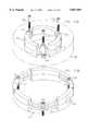
- FIG. 4is a pictorial illustration of a passive transceiver mountable inside a fuel inlet pipe in accordance with a preferred embodiment of the present invention and an installation tool thereof;
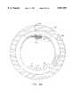
- FIG. 5is a plan view of a transceiver of the type shown in FIG. 4 located inside a fuel inlet pipe of a vehicle;
- FIGS. 6A and 6Bare detailed partial illustrations of two stages in the installation of the transceiver of FIGS. 4 and 5 within a fuel inlet pipe, as viewed in the direction of the arrow VI, in accordance with a preferred embodiment of the present invention
- FIGS. 7A and 7Bare sectional illustrations, taken along the lines 7A--7A and 7B--7B in FIGS. 6A and 6B, respectively;
- FIGS. 8A and 8Bare plan views of two stages in the installation of the transceiver of FIGS. 4 and 5 within a fuel inlet pipe in accordance with a preferred embodiment of the present invention
- FIGS. 9A and 9Bare sectional illustrations showing part of the internal construction of the transceiver of FIG. 4, respectively taken along the lines 9A--9A in FIG. 4 and the lines 9B--9B in FIG. 9A;
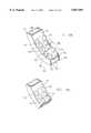
- FIGS. 10A and 10Bare pictorial illustrations of two stages in the installation of an alternative embodiment of transceiver in a fuel inlet pipe.
- FIG. 1illustrates a fueling system constructed and operative in accordance with a preferred embodiment of the present invention.
- the fueling systemcomprises at least one and preferably a plurality of fuel dispensing stations 10, each including at least one fuel pump 12 and associated delivery nozzle 14.
- FIGS. 2A, 2B and 2Cas known in applicant/assignee's existing prior art Fuelomat (Trademark) automated fuel management system, there is provided an inductive communication loop 20 associated with each delivery nozzle 22, and a data receiver 24 (FIG. 1) connected thereto by wiring 26 or wireless links for receiving data via the inductive communication loop 20.
- FIG. 2Bshows an alternative embodiment of an inductive communication loop 20'.
- the prior art Fuelomat fueling systemrequired that the inductive communication loop 41 mounted on the inlet pipe 42 be powered by the vehicle battery and coupled to the vehicle odometer and possibly other vehicle instruments. This resulted in a relatively expensive vehicle fueling identification unit and relatively expensive installation thereof.
- the present inventionreplaces the vehicle powered unit of the prior art with a self-contained passive vehicle mounted fueling system identification unit 40, as shown in FIG. 2D including an inductive communication loop 41, (FIG. 2D) arranged to surround the fuel intake pipe 42 of a vehicle and circuitry powered by electric power inductively received by the loop for transmitting via the loop at least one of the following parameters: vehicle identification number, credit information, required fuel particulars.
- a self-contained passive vehicle mounted fueling system identification unit 40including an inductive communication loop 41, (FIG. 2D) arranged to surround the fuel intake pipe 42 of a vehicle and circuitry powered by electric power inductively received by the loop for transmitting via the loop at least one of the following parameters: vehicle identification number, credit information, required fuel particulars.
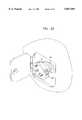
- Typical mounting of the self-contained passive vehicle mounted fueling system identification unit 40' onto the fuel intake pipe 42 of a vehicleis shown in FIG. 2C.
- unit 40'is normally covered and out of sight during vehicle fueling and is retained with respect to the fuel intake pipe 42 against unacceptable vibrations, displacements and impacts.
- FIG. 3Aillustrates, in simplified block diagram form, fueling station mounted apparatus forming part of the fueling system of the present invention.
- the apparatus of FIG. 3Aincludes an inductive loop, such as loop 20, typically formed of a plurality of windings of an insulated conductor.
- loop 20is coupled via a conventional interface 21, to a data receiver 24 for reception of vehicle identification data from vehicles being fueled.
- Loop 20may also be coupled to a data source (not shown) for data transmission to vehicles, if such functionality is desired.
- electrical poweris transmitted from the fueling station mounted apparatus to the vehicle mounted apparatus, obviating the need for an electrical power connection of the vehicle mounted apparatus to the vehicle battery and thus greatly simplifying and reducing the cost of the vehicle mounted apparatus.
- the electrical poweris provided by an oscillator 50, which outputs AC electrical power, via any suitable interface 52, to loop 20, which is the same loop which is used for data communication.
- oscillator 50which outputs AC electrical power, via any suitable interface 52, to loop 20, which is the same loop which is used for data communication.
- loop 20in propinquity to vehicle mounted loop 41' during fueling inductively couples the two loops and is operative to transfer AC electrical power in a wireless and contactless manner from loop 20 to loop 41'.
- loop 41'which may be identical to loop 20, is coupled to a power supply 54, such as capacitor or battery, which stores electrical power received inductively from loop 20 and is also coupled via a data transmission interface 56 to digital logic circuitry 58.
- Digital logic circuitry 58typically interfaces with a storage device such as an EPROM 60 and may also be associated with an auxiliary connector 62.
- a tamper-activated self destruct device 64such as a microswitch controlled data source, may be provided so as to automatically and irreversibly deactivate the digital logic 58 in response to tampering.
- the EPROM 60typically stores various vehicle and fueling system identification parameters, such as vehicle identification number, credit information, required fuel particulars. Other parameters may be stored as well. These parameters are transmitted by digital logic circuitry 58 via loops 41' and 20 to data receiver 24 during fueling of a vehicle.
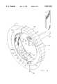
- FIGS. 4 and 5illustrate another preferred embodiment of an identification unit assembly 80 which is arranged to be mounted inside a fuel inlet pipe 82.
- the identification unitwhich typically comprises a transceiver 84 is disposed in a generally annular housing assembly 86 which includes a first portion 88 which subtends approximately 270 degrees of arc, a second portion 89 which also subtends approximately 270 degrees of arc and an extendible band 90.
- the two ends of the second portion 89are shown as dashed hidden lines 89A and 89B. It is seen in FIGS.
- the cross-sectional shape of the first portion 88resembles the letter U
- the cross-sectional shape of the second portion 89resembles an inverted U.
- the second portion 89fits inside the first portion 88 and as is seen particularly in FIG. 4, the open end of the second portion 89, that is the open section between lines 89A and 89B, is not aligned with the open end of the first portion 88, but rather is inside the first portion 88.
- the first portion 88is provided with a first plurality of tabs 92 and the second portion 89 is provided with a second plurality of tabs 94.
- the first plurality of tabs 92passes through the second portion 89 and the band 90
- the second plurality of tabs 94passes through the band 90. Both pluralities of tabs are bent over in the final assembly to securely fasten the band 90 to the first 88 and second 89 portions.
- the transceiver 84is mounted in a recess between the first 88 and second 89 portions.
- the transceiver 84may be mounted by any method, such as with mechanical fasteners or by bonding.
- the housing assembly 86is expandable and thus can be adapted for mounting in fuel intake pipes with different diameters.
- a ratchet type securing assembly 96is operative to expand the band 90 outwardly causing the band 90 to press the second portion 89 outwardly against the first portion 88, which in turn presses against the interior of the fuel inlet pipe 82 and thus secures the housing assembly 86 in tight engagement with the interior of the fuel inlet pipe 82.
- the securing assembly 96comprises a plurality of engagement teeth 100, as shown clearly in FIGS. 7A and 7B.
- the teeth 100are adapted to engage with a plurality of notches 102 on the band 90. It is a particular feature of the present invention that only one tooth of the plurality of teeth 100 is engaged at one time with any one of the notches 102.
- a tool 104engages one of the notches 102 and is operative to advance the band 90 notch by notch in the direction indicated by the arrow 106 in FIGS. 7A and 7B.
- FIG. 7Ainitially only a tooth indicated by reference numeral 108 is engaged in a notch indicated by reference numeral 110. All other teeth 100 are misaligned with their corresponding notches 102. As the tool 104 is turned in the direction indicated by arrows 112, the band 90 is advanced in the direction 106 and the tooth 108 becomes disengaged from notch 110 and a different tooth 114 becomes engaged in a notch 116 as is shown in FIG. 7B.
- This arrangement of teeth and notchesallows for fine incremental expansion of the band 90 and operates on the principle of a Vernier scale in which only one tooth is aligned with a notch at a time. Additionally in a preferred embodiment of the present invention, the teeth 100 are divided into two parallel, slightly offset groups of upper and lower teeth as is shown in FIGS. 7A and 7B. This arrangement conserves volume.
- advancement of the band 90 by means of the tool 104causes the band 90 to press against the second portion 89 which in turn presses against the first portion 88 which presses against the interior of the fuel pipe 82, thereby tightening the housing assembly 86 against the interior of the fuel inlet pipe 82.
- the band 90presses against the second portion 89 which then presses against the first portion 83 because all three are attached to one another at the bottom by means of the tabs 92 and 94.
- the ends of the band 90 near the assembly 96are free to expand outwardly and to press against the second portion 89.
- FIGS. 8A and 8Billustrate the sequential tightening of housing assembly 86 in inlet pipe 82.
- FIGS. 10A and 10Billustrate an alternative construction of a identification unit transceiver useful in the system of the present invention.
- a housing assembly 120 containing an identification unit 122is formed with a plurality of compression activated expansion joints 124.
- a plurality of screws 126operatively engage the expansion joints 124, which may have threading (not shown) for engagement with the screws.
Landscapes
- Engineering & Computer Science (AREA)
- Physics & Mathematics (AREA)
- Business, Economics & Management (AREA)
- General Physics & Mathematics (AREA)
- Mechanical Engineering (AREA)
- Theoretical Computer Science (AREA)
- Health & Medical Sciences (AREA)
- Economics (AREA)
- Computer Networks & Wireless Communication (AREA)
- General Business, Economics & Management (AREA)
- Strategic Management (AREA)
- Human Resources & Organizations (AREA)
- Accounting & Taxation (AREA)
- Primary Health Care (AREA)
- Marketing (AREA)
- General Health & Medical Sciences (AREA)
- Water Supply & Treatment (AREA)
- Public Health (AREA)
- Mathematical Physics (AREA)
- Microelectronics & Electronic Packaging (AREA)
- Tourism & Hospitality (AREA)
- Life Sciences & Earth Sciences (AREA)
- Sustainable Development (AREA)
- Sustainable Energy (AREA)
- Chemical & Material Sciences (AREA)
- Combustion & Propulsion (AREA)
- Transportation (AREA)
- Cooling, Air Intake And Gas Exhaust, And Fuel Tank Arrangements In Propulsion Units (AREA)
Abstract
Description
Claims (3)
Priority Applications (1)
| Application Number | Priority Date | Filing Date | Title |
|---|---|---|---|
| US08/649,648US5857501A (en) | 1993-11-28 | 1994-11-28 | Fueling system |
Applications Claiming Priority (4)
| Application Number | Priority Date | Filing Date | Title |
|---|---|---|---|
| IL107784AIL107784A (en) | 1993-11-28 | 1993-11-28 | Fueling system |
| IL107784 | 1993-11-28 | ||
| US08/649,648US5857501A (en) | 1993-11-28 | 1994-11-28 | Fueling system |
| PCT/US1994/013611WO1995014612A1 (en) | 1993-11-28 | 1994-11-28 | Fueling system |
Publications (1)
| Publication Number | Publication Date |
|---|---|
| US5857501Atrue US5857501A (en) | 1999-01-12 |
Family
ID=26322730
Family Applications (1)
| Application Number | Title | Priority Date | Filing Date |
|---|---|---|---|
| US08/649,648Expired - LifetimeUS5857501A (en) | 1993-11-28 | 1994-11-28 | Fueling system |
Country Status (1)
| Country | Link |
|---|---|
| US (1) | US5857501A (en) |
Cited By (40)
| Publication number | Priority date | Publication date | Assignee | Title |
|---|---|---|---|---|
| WO1999058356A1 (en)* | 1998-05-11 | 1999-11-18 | On Track Innovations Ltd. | Self-closing cap for the filling neck of a container |
| US6116298A (en)* | 1996-10-28 | 2000-09-12 | Hi-G-Tek Ltd. | Fueling system |
| EP1099664A1 (en) | 1999-11-10 | 2001-05-16 | Hi-G-Tek Ltd | Fluid supply system with tank identification reader |
| US20020046117A1 (en)* | 1997-09-26 | 2002-04-18 | Marion Kenneth O. | Fuel dispensing and retail system providing a transaction discount for transponder use |
| US6374870B1 (en) | 1999-08-11 | 2002-04-23 | Ide Til Produkt As | Fuel dispensing nozzle |
| EP1250574A4 (en)* | 1999-07-09 | 2002-10-23 | Warren Rogers Associates Inc | Method and apparatus for monitoring operational performance of fluid storage systems |
| US6497363B1 (en) | 1998-01-15 | 2002-12-24 | Del-Pak Systems (1983) Ltd. | Electrical connector with identification chip |
| DE10126208A1 (en)* | 2001-05-30 | 2003-01-16 | Bayerische Motoren Werke Ag | Motor vehicle fuel tank with a filler neck for holding a fuel nozzle for diesel fuel |
| US20030125836A1 (en)* | 2002-11-23 | 2003-07-03 | Munroe Chirnomas | Method and apparatus for controlling a vending machine |
| US6648032B1 (en) | 2002-06-13 | 2003-11-18 | Orpak Industries (1983) Ltd. | Apparatus and method for facilitating fueling a vehicle |
| US6649829B2 (en) | 2001-05-21 | 2003-11-18 | Colder Products Company | Connector apparatus and method for connecting the same for controlling fluid dispensing |
| US6691061B1 (en) | 1996-06-04 | 2004-02-10 | Warren Rogers Associates, Inc. | Method and apparatus for monitoring operational performance of fluid storage systems |
| US20040044497A1 (en)* | 1996-06-04 | 2004-03-04 | Warren Rogers Associates, Inc. | Method and apparatus for monitoring operational performance of fluid storage systems |
| US20040117135A1 (en)* | 1996-06-04 | 2004-06-17 | Warren Rogers Associates, Inc. | Method and apparatus for monitoring operational performance of fluid storage systems |
| US20050061390A1 (en)* | 2003-08-20 | 2005-03-24 | Mathis James E. | Method and apparatus for data transfer |
| US20050092388A1 (en)* | 2003-10-31 | 2005-05-05 | Cellex Power Products, Inc. | Fuel dispensing system and method |
| US6925397B2 (en) | 1994-11-29 | 2005-08-02 | Warren Rogers Associates | Meter calibration accuracy |
| US6962177B1 (en) | 2004-07-27 | 2005-11-08 | Mccommons James A | Locking fuel pump dispenser |
| WO2006079677A1 (en)* | 2005-01-26 | 2006-08-03 | De La Cueva Moreno Jorge Migue | Safety device for filling motor vehicles with fuel |
| US20070231638A1 (en)* | 2006-03-29 | 2007-10-04 | Casio Computer Co., Ltd. | Fuel feeder, electric equipment and fuel feed system thereof |
| WO2008090539A2 (en) | 2007-01-25 | 2008-07-31 | Petratec International Ltd. | Devices and methods useful for authorizing purchases associated with a vehicle |
| US20080223481A1 (en)* | 2005-08-01 | 2008-09-18 | Gammon James H | Fluid Dispensing System |
| EP1974977A1 (en) | 2007-03-31 | 2008-10-01 | G. Cartier Technologies | Device for avoiding errors in delivering fluid to a container |
| FR2914293A1 (en)* | 2007-03-31 | 2008-10-03 | Cartier Technologies Soc Par A | DEVICE FOR PREVENTING FLUID SUPPLY ERRORS FROM A RESERVE |
| US7490112B1 (en) | 1997-04-15 | 2009-02-10 | Intellisync Corporation | System and methods for synchronizing information among disparate datasets |
| US7571139B1 (en) | 1999-02-19 | 2009-08-04 | Giordano Joseph A | System and method for processing financial transactions |
| FR2928908A1 (en)* | 2008-03-18 | 2009-09-25 | Cartier Technologies Soc Par A | Fluid e.g. fuel, supply controlling device for e.g. oil engine vehicle, has detection units sensitive to current or voltage waveform in primary coil and to distinguish presence and type of fluid supply nozzle based on waveform |
| US7597252B1 (en) | 2006-04-14 | 2009-10-06 | Dewitt Mike R | Fuel pumping system and method |
| US20100180983A1 (en)* | 2009-01-16 | 2010-07-22 | Ford Motor Company | Fueling system and method |
| US20100276031A1 (en)* | 2009-03-31 | 2010-11-04 | Denso Corporation | Fluid charging system, movable object, supply facilitly, and method for controlling fluid charge |
| US20110018713A1 (en)* | 2008-02-21 | 2011-01-27 | Roseman Engineering Ltd. | Wireless Identification Device With Tamper Protection And Method Of Operating Thereof |
| US8068027B2 (en) | 2004-03-30 | 2011-11-29 | Hi-G-Tek Ltd. | Monitorable locking assemblies |
| US20120305127A1 (en)* | 2011-06-03 | 2012-12-06 | Curtis Roys | Method and Structure for Prevention of Incorrect Fueling Operations for Diesel-Powered Vehicles |
| US8538801B2 (en) | 1999-02-19 | 2013-09-17 | Exxonmobile Research & Engineering Company | System and method for processing financial transactions |
| US8844587B1 (en) | 2013-11-01 | 2014-09-30 | James A. McCommons | Locking fuel pump dispenser |
| US20140311618A1 (en)* | 2011-06-03 | 2014-10-23 | Curtis Roys | Method and Structure for Prevention of Incorrect Fueling Operations |
| US20150161590A1 (en)* | 2013-12-06 | 2015-06-11 | Mastercard Asia Pacific Pte. Ltd. | System and method for conducting a transaction using a fuel dispensing nozzle |
| USD822072S1 (en) | 2015-12-10 | 2018-07-03 | Curtis Alan Roys | Diesel fuel guard |
| PL426200A1 (en)* | 2018-07-03 | 2019-10-21 | 3 M Spółka Z Ograniczoną Odpowiedzialnością | Unit warning against refuelling of cars with compression-ignition engines from the petrol pump |
| US11247894B2 (en)* | 2019-09-12 | 2022-02-15 | Dean A. Drake | Vehicular fuel-selecting system, apparatus, and method |
Citations (19)
| Publication number | Priority date | Publication date | Assignee | Title |
|---|---|---|---|---|
| US3148713A (en)* | 1962-02-20 | 1964-09-15 | Stanley P Lewis | Safety means for liquid dispensing nozzles |
| US3642036A (en)* | 1970-04-30 | 1972-02-15 | Irwin Ginsburgh | Automatic fueling system for automobiles |
| US4095214A (en)* | 1976-06-17 | 1978-06-13 | Knogo Corporation | Electronic monitoring system and responder device |
| US4109686A (en)* | 1977-07-06 | 1978-08-29 | Phillips Jacque R | Tax adjusting vehicle gasoline filler equipment |
| GB1577920A (en)* | 1976-11-01 | 1980-10-29 | Nedap Nv | Detection plate for identification systems |
| US4263945A (en)* | 1979-06-20 | 1981-04-28 | Ness Bradford O Van | Automatic fuel dispensing control system |
| FR2502134A1 (en)* | 1981-03-19 | 1982-09-24 | Lebret Eric | Anti-fraud device for fluid dispenser e.g. petrol pump - includes magnetic sensors on dispenser responding to coded magnets around filler pipe of receiving tank |
| US4469149A (en)* | 1981-06-23 | 1984-09-04 | Monitronix Systems Limited | Monitored delivery systems |
| US4544005A (en)* | 1983-05-06 | 1985-10-01 | Atlas Pacific Engineering Company | Can detection and switch mechanism for can filling apparatus |
| US4846233A (en)* | 1985-06-03 | 1989-07-11 | N.V. Nederlandsche Apparatenfabriek Nedap | System for selectively emptying or filling a tank |
| US4934419A (en)* | 1988-06-30 | 1990-06-19 | Analytical Instruments Limited | Fleet data monitoring system |
| US4977935A (en)* | 1989-10-20 | 1990-12-18 | General Electric Company | Interlock system |
| US5070293A (en)* | 1989-03-02 | 1991-12-03 | Nippon Soken, Inc. | Electric power transmitting device with inductive coupling |
| US5095309A (en)* | 1989-05-26 | 1992-03-10 | Trovan Limited | Method and apparatus for modulating and detecting a subcarrier signal for an inductively coupled transponder |
| EP0476858A1 (en)* | 1990-08-27 | 1992-03-25 | Michael C. Ryan | Fluid delivery control apparatus |
| US5156198A (en)* | 1991-02-20 | 1992-10-20 | Hall Gerald L | Pump lock fuel system |
| US5249612A (en)* | 1992-07-24 | 1993-10-05 | Bti, Inc. | Apparatus and methods for controlling fluid dispensing |
| US5339250A (en)* | 1990-06-15 | 1994-08-16 | Inn Room Systems, Inc. | Interactive network for remotely controlled hotel vending systems |
| US5605182A (en)* | 1995-04-20 | 1997-02-25 | Dover Corporation | Vehicle identification system for a fuel dispenser |
- 1994
- 1994-11-28USUS08/649,648patent/US5857501A/ennot_activeExpired - Lifetime
Patent Citations (20)
| Publication number | Priority date | Publication date | Assignee | Title |
|---|---|---|---|---|
| US3148713A (en)* | 1962-02-20 | 1964-09-15 | Stanley P Lewis | Safety means for liquid dispensing nozzles |
| US3642036A (en)* | 1970-04-30 | 1972-02-15 | Irwin Ginsburgh | Automatic fueling system for automobiles |
| US4095214A (en)* | 1976-06-17 | 1978-06-13 | Knogo Corporation | Electronic monitoring system and responder device |
| GB1577920A (en)* | 1976-11-01 | 1980-10-29 | Nedap Nv | Detection plate for identification systems |
| US4109686A (en)* | 1977-07-06 | 1978-08-29 | Phillips Jacque R | Tax adjusting vehicle gasoline filler equipment |
| US4263945A (en)* | 1979-06-20 | 1981-04-28 | Ness Bradford O Van | Automatic fuel dispensing control system |
| FR2502134A1 (en)* | 1981-03-19 | 1982-09-24 | Lebret Eric | Anti-fraud device for fluid dispenser e.g. petrol pump - includes magnetic sensors on dispenser responding to coded magnets around filler pipe of receiving tank |
| US4469149A (en)* | 1981-06-23 | 1984-09-04 | Monitronix Systems Limited | Monitored delivery systems |
| US4544005A (en)* | 1983-05-06 | 1985-10-01 | Atlas Pacific Engineering Company | Can detection and switch mechanism for can filling apparatus |
| US4846233A (en)* | 1985-06-03 | 1989-07-11 | N.V. Nederlandsche Apparatenfabriek Nedap | System for selectively emptying or filling a tank |
| US4934419A (en)* | 1988-06-30 | 1990-06-19 | Analytical Instruments Limited | Fleet data monitoring system |
| US5070293A (en)* | 1989-03-02 | 1991-12-03 | Nippon Soken, Inc. | Electric power transmitting device with inductive coupling |
| US5095309A (en)* | 1989-05-26 | 1992-03-10 | Trovan Limited | Method and apparatus for modulating and detecting a subcarrier signal for an inductively coupled transponder |
| US4977935A (en)* | 1989-10-20 | 1990-12-18 | General Electric Company | Interlock system |
| US5339250A (en)* | 1990-06-15 | 1994-08-16 | Inn Room Systems, Inc. | Interactive network for remotely controlled hotel vending systems |
| EP0476858A1 (en)* | 1990-08-27 | 1992-03-25 | Michael C. Ryan | Fluid delivery control apparatus |
| US5204819A (en)* | 1990-08-27 | 1993-04-20 | Ryan Michael C | Fluid delivery control apparatus |
| US5156198A (en)* | 1991-02-20 | 1992-10-20 | Hall Gerald L | Pump lock fuel system |
| US5249612A (en)* | 1992-07-24 | 1993-10-05 | Bti, Inc. | Apparatus and methods for controlling fluid dispensing |
| US5605182A (en)* | 1995-04-20 | 1997-02-25 | Dover Corporation | Vehicle identification system for a fuel dispenser |
Cited By (63)
| Publication number | Priority date | Publication date | Assignee | Title |
|---|---|---|---|---|
| US6925397B2 (en) | 1994-11-29 | 2005-08-02 | Warren Rogers Associates | Meter calibration accuracy |
| US20040044497A1 (en)* | 1996-06-04 | 2004-03-04 | Warren Rogers Associates, Inc. | Method and apparatus for monitoring operational performance of fluid storage systems |
| US20040117135A1 (en)* | 1996-06-04 | 2004-06-17 | Warren Rogers Associates, Inc. | Method and apparatus for monitoring operational performance of fluid storage systems |
| US6909986B2 (en) | 1996-06-04 | 2005-06-21 | Warren Rogers Associates, Inc. | Method and apparatus for monitoring operational performance of fluid storage systems |
| US6691061B1 (en) | 1996-06-04 | 2004-02-10 | Warren Rogers Associates, Inc. | Method and apparatus for monitoring operational performance of fluid storage systems |
| US6934644B2 (en) | 1996-06-04 | 2005-08-23 | Warren Rogers Associates, Inc. | Method and apparatus for monitoring operational performance of fluid storage systems |
| US6116298A (en)* | 1996-10-28 | 2000-09-12 | Hi-G-Tek Ltd. | Fueling system |
| US7490112B1 (en) | 1997-04-15 | 2009-02-10 | Intellisync Corporation | System and methods for synchronizing information among disparate datasets |
| US7027890B2 (en)* | 1997-09-26 | 2006-04-11 | Gilbarco Inc. | Fuel dispensing system for cash customers |
| US20020046117A1 (en)* | 1997-09-26 | 2002-04-18 | Marion Kenneth O. | Fuel dispensing and retail system providing a transaction discount for transponder use |
| US6813609B2 (en) | 1997-09-26 | 2004-11-02 | Gilbarco Inc. | Loyalty rewards for cash customers at a fuel dispensing system |
| US7020541B2 (en)* | 1997-09-26 | 2006-03-28 | Gilbarco Inc. | Fuel dispensing system for cash customers |
| US7289877B2 (en)* | 1997-09-26 | 2007-10-30 | Gilbarco Inc. | Fuel dispensing system for cash customers |
| US6497363B1 (en) | 1998-01-15 | 2002-12-24 | Del-Pak Systems (1983) Ltd. | Electrical connector with identification chip |
| WO1999058356A1 (en)* | 1998-05-11 | 1999-11-18 | On Track Innovations Ltd. | Self-closing cap for the filling neck of a container |
| US6209592B1 (en)* | 1998-05-11 | 2001-04-03 | On Track Innovations Ltd. | Self-closing cap for the filling neck of a container |
| US8538801B2 (en) | 1999-02-19 | 2013-09-17 | Exxonmobile Research & Engineering Company | System and method for processing financial transactions |
| US7571139B1 (en) | 1999-02-19 | 2009-08-04 | Giordano Joseph A | System and method for processing financial transactions |
| EP1250574A4 (en)* | 1999-07-09 | 2002-10-23 | Warren Rogers Associates Inc | Method and apparatus for monitoring operational performance of fluid storage systems |
| US6374870B1 (en) | 1999-08-11 | 2002-04-23 | Ide Til Produkt As | Fuel dispensing nozzle |
| US6394150B1 (en) | 1999-11-10 | 2002-05-28 | Hi-G-Tek Ltd. | Computerized fluid supply systems |
| EP1099664A1 (en) | 1999-11-10 | 2001-05-16 | Hi-G-Tek Ltd | Fluid supply system with tank identification reader |
| US20050211934A1 (en)* | 2001-05-21 | 2005-09-29 | Colder Products Company | Connector apparatus and method for connecting the same for controlling fluid dispensing |
| US7647954B2 (en) | 2001-05-21 | 2010-01-19 | Colder Products Company | Connector apparatus and method for connecting the same for controlling fluid dispensing |
| US6897374B2 (en) | 2001-05-21 | 2005-05-24 | Colder Products Company | Connector apparatus and method for connecting the same |
| US6649829B2 (en) | 2001-05-21 | 2003-11-18 | Colder Products Company | Connector apparatus and method for connecting the same for controlling fluid dispensing |
| DE10126208A1 (en)* | 2001-05-30 | 2003-01-16 | Bayerische Motoren Werke Ag | Motor vehicle fuel tank with a filler neck for holding a fuel nozzle for diesel fuel |
| US6648032B1 (en) | 2002-06-13 | 2003-11-18 | Orpak Industries (1983) Ltd. | Apparatus and method for facilitating fueling a vehicle |
| US20030125836A1 (en)* | 2002-11-23 | 2003-07-03 | Munroe Chirnomas | Method and apparatus for controlling a vending machine |
| US20050061390A1 (en)* | 2003-08-20 | 2005-03-24 | Mathis James E. | Method and apparatus for data transfer |
| US20070068596A1 (en)* | 2003-10-31 | 2007-03-29 | Cellex Power Products, Inc. | Fuel dispensing system and method |
| US7412994B2 (en) | 2003-10-31 | 2008-08-19 | Cellex Power Products, Inc. | Fuel dispensing system and method |
| US20050092388A1 (en)* | 2003-10-31 | 2005-05-05 | Cellex Power Products, Inc. | Fuel dispensing system and method |
| US7171989B2 (en) | 2003-10-31 | 2007-02-06 | Cellex Power Products, Inc. | Fuel dispensing system and method |
| US8068027B2 (en) | 2004-03-30 | 2011-11-29 | Hi-G-Tek Ltd. | Monitorable locking assemblies |
| US6962177B1 (en) | 2004-07-27 | 2005-11-08 | Mccommons James A | Locking fuel pump dispenser |
| WO2006079677A1 (en)* | 2005-01-26 | 2006-08-03 | De La Cueva Moreno Jorge Migue | Safety device for filling motor vehicles with fuel |
| US20080223481A1 (en)* | 2005-08-01 | 2008-09-18 | Gammon James H | Fluid Dispensing System |
| US20070231638A1 (en)* | 2006-03-29 | 2007-10-04 | Casio Computer Co., Ltd. | Fuel feeder, electric equipment and fuel feed system thereof |
| US7591288B2 (en)* | 2006-03-29 | 2009-09-22 | Casio Computer Co., Ltd. | Fuel feeder, electric equipment and fuel feed system thereof |
| US7597252B1 (en) | 2006-04-14 | 2009-10-06 | Dewitt Mike R | Fuel pumping system and method |
| WO2008090539A2 (en) | 2007-01-25 | 2008-07-31 | Petratec International Ltd. | Devices and methods useful for authorizing purchases associated with a vehicle |
| FR2914292A1 (en)* | 2007-03-31 | 2008-10-03 | Cartier Technologies Soc Par A | Fluid e.g. fuel, supply controlling device for e.g. oil engine vehicle, has detection units sensitive to current or voltage waveform in primary coil and to distinguish presence and type of fluid supply nozzle based on waveform |
| FR2914293A1 (en)* | 2007-03-31 | 2008-10-03 | Cartier Technologies Soc Par A | DEVICE FOR PREVENTING FLUID SUPPLY ERRORS FROM A RESERVE |
| US20080236685A1 (en)* | 2007-03-31 | 2008-10-02 | G. Cartier Technologies | Device for avoiding errors in delivering fluid to a container |
| EP1974977A1 (en) | 2007-03-31 | 2008-10-01 | G. Cartier Technologies | Device for avoiding errors in delivering fluid to a container |
| US8186394B2 (en) | 2007-03-31 | 2012-05-29 | G. Cartier Technologies | Device for avoiding errors in delivering fluid to a container |
| US20110018713A1 (en)* | 2008-02-21 | 2011-01-27 | Roseman Engineering Ltd. | Wireless Identification Device With Tamper Protection And Method Of Operating Thereof |
| FR2928908A1 (en)* | 2008-03-18 | 2009-09-25 | Cartier Technologies Soc Par A | Fluid e.g. fuel, supply controlling device for e.g. oil engine vehicle, has detection units sensitive to current or voltage waveform in primary coil and to distinguish presence and type of fluid supply nozzle based on waveform |
| US20100180983A1 (en)* | 2009-01-16 | 2010-07-22 | Ford Motor Company | Fueling system and method |
| US8684044B2 (en)* | 2009-03-31 | 2014-04-01 | Denso Corporation | Fluid charging system, movable object, supply facility, and method for controlling fluid charge |
| US20100276031A1 (en)* | 2009-03-31 | 2010-11-04 | Denso Corporation | Fluid charging system, movable object, supply facilitly, and method for controlling fluid charge |
| US9133013B2 (en)* | 2011-06-03 | 2015-09-15 | Curtis Roys | Method and structure for prevention of incorrect fueling operations |
| US8678049B2 (en)* | 2011-06-03 | 2014-03-25 | Curtis Roys | Method and structure for prevention of incorrect fueling operations for diesel-powered vehicles |
| US20140311618A1 (en)* | 2011-06-03 | 2014-10-23 | Curtis Roys | Method and Structure for Prevention of Incorrect Fueling Operations |
| US20120305127A1 (en)* | 2011-06-03 | 2012-12-06 | Curtis Roys | Method and Structure for Prevention of Incorrect Fueling Operations for Diesel-Powered Vehicles |
| US9415995B2 (en) | 2011-06-03 | 2016-08-16 | Curtis Alan Roys | Method and structure for prevention of incorrect fueling operations |
| US8844587B1 (en) | 2013-11-01 | 2014-09-30 | James A. McCommons | Locking fuel pump dispenser |
| US20150161590A1 (en)* | 2013-12-06 | 2015-06-11 | Mastercard Asia Pacific Pte. Ltd. | System and method for conducting a transaction using a fuel dispensing nozzle |
| USD822072S1 (en) | 2015-12-10 | 2018-07-03 | Curtis Alan Roys | Diesel fuel guard |
| US10081241B2 (en) | 2015-12-10 | 2018-09-25 | Curtis Alan Roys | Diesel fuel guard |
| PL426200A1 (en)* | 2018-07-03 | 2019-10-21 | 3 M Spółka Z Ograniczoną Odpowiedzialnością | Unit warning against refuelling of cars with compression-ignition engines from the petrol pump |
| US11247894B2 (en)* | 2019-09-12 | 2022-02-15 | Dean A. Drake | Vehicular fuel-selecting system, apparatus, and method |
Similar Documents
| Publication | Publication Date | Title |
|---|---|---|
| US5857501A (en) | Fueling system | |
| EP0729426B1 (en) | Fueling system | |
| US5156198A (en) | Pump lock fuel system | |
| US6116298A (en) | Fueling system | |
| US6581619B1 (en) | Method and device for the supply of electrical loads in or on a pneumatic device with electrical power energy | |
| AU684031B3 (en) | Tyre pressure monitoring transponder mounted on a tyre valve | |
| US6571151B1 (en) | Wireless nozzle interface for a fuel dispenser | |
| US6466842B1 (en) | Dispensing system for preventing unauthorized fueling | |
| EP0245606B1 (en) | Automatic/remote rf instrument reading system | |
| US7907058B2 (en) | Devices and methods useful for authorizing purchases associated with a vehicle | |
| MXPA00001309A (en) | Method and apparatus for a remote tire pressure monitoring system. | |
| GB2338835A (en) | Multi-phase transmitter with single receive antenna for transponder interrogator | |
| ITRM990454A1 (en) | RESPONDING DEVICE. | |
| KR20000070871A (en) | Code signal transmitter, especially for an anti-theft system in a motor vehicle | |
| EP1488971A3 (en) | Vehicle theft-prevention device | |
| EP1346888A3 (en) | Wireless entry system for vehicle | |
| AU707494B2 (en) | Providing service to a vehicle | |
| EP0723892A2 (en) | System in a vehicle, and a system for working the method | |
| EP0943584B1 (en) | Fueling system | |
| IL111802A (en) | Fueling system | |
| US20030201872A1 (en) | Method, device and system for providing anti-theft protection for electrical devices, particularly controllers in vehicle refueling systems | |
| HU216494B (en) | Electronic locking mechanism | |
| US20070152801A1 (en) | System for harmonizing a motor vehicle's status information between at least two ID transmitters | |
| US6873247B2 (en) | Combined vehicle immobilizing and steering column control system | |
| KR20010113194A (en) | Interface aqpparatus for remote diagnosis of vehicle |
Legal Events
| Date | Code | Title | Description |
|---|---|---|---|
| AS | Assignment | Owner name:RAPAC NETWORK INTERNATIONAL, INC., NEW JERSEY Free format text:ASSIGNMENT OF ASSIGNORS INTEREST;ASSIGNORS:KELERICH, DAVID;TALMOR, DOV;REEL/FRAME:008099/0721 Effective date:19960717 | |
| AS | Assignment | Owner name:DELEK THE ISRAEL FUEL CORPORATION LTD., ISRAEL Free format text:ASSIGNMENT OF ASSIGNORS INTEREST;ASSIGNOR:RAPAC NETWORK INTERNATIONAL, INC.;REEL/FRAME:009654/0226 Effective date:19980505 Owner name:SONOL ISRAEL LTD., ISRAEL Free format text:ASSIGNMENT OF ASSIGNORS INTEREST;ASSIGNOR:RAPAC NETWORK INTERNATIONAL, INC.;REEL/FRAME:009654/0226 Effective date:19980505 Owner name:DELEK (OVERSEAS) INC., DELAWARE Free format text:ASSIGNMENT OF ASSIGNORS INTEREST;ASSIGNOR:RAPAC NETWORK INTERNATIONAL, INC.;REEL/FRAME:009654/0226 Effective date:19980505 Owner name:SANAPCO BANK STREET CORPORATION, NEW YORK Free format text:ASSIGNMENT OF ASSIGNORS INTEREST;ASSIGNOR:RAPAC NETWORK INTERNATIONAL, INC.;REEL/FRAME:009654/0226 Effective date:19980505 | |
| STCF | Information on status: patent grant | Free format text:PATENTED CASE | |
| FPAY | Fee payment | Year of fee payment:4 | |
| FPAY | Fee payment | Year of fee payment:8 | |
| FPAY | Fee payment | Year of fee payment:12 | |
| SULP | Surcharge for late payment | Year of fee payment:11 |