US5857144A - In-band vehicular repeater for trunked radio system - Google Patents
In-band vehicular repeater for trunked radio systemDownload PDFInfo
- Publication number
- US5857144A US5857144AUS08/694,745US69474596AUS5857144AUS 5857144 AUS5857144 AUS 5857144AUS 69474596 AUS69474596 AUS 69474596AUS 5857144 AUS5857144 AUS 5857144A
- Authority
- US
- United States
- Prior art keywords
- radio
- repeater
- unit
- portable
- base site
- Prior art date
- Legal status (The legal status is an assumption and is not a legal conclusion. Google has not performed a legal analysis and makes no representation as to the accuracy of the status listed.)
- Expired - Lifetime
Links
Images


Classifications
- H—ELECTRICITY
- H04—ELECTRIC COMMUNICATION TECHNIQUE
- H04W—WIRELESS COMMUNICATION NETWORKS
- H04W84/00—Network topologies
- H04W84/02—Hierarchically pre-organised networks, e.g. paging networks, cellular networks, WLAN [Wireless Local Area Network] or WLL [Wireless Local Loop]
- H04W84/04—Large scale networks; Deep hierarchical networks
- H04W84/08—Trunked mobile radio systems
- Y—GENERAL TAGGING OF NEW TECHNOLOGICAL DEVELOPMENTS; GENERAL TAGGING OF CROSS-SECTIONAL TECHNOLOGIES SPANNING OVER SEVERAL SECTIONS OF THE IPC; TECHNICAL SUBJECTS COVERED BY FORMER USPC CROSS-REFERENCE ART COLLECTIONS [XRACs] AND DIGESTS
- Y02—TECHNOLOGIES OR APPLICATIONS FOR MITIGATION OR ADAPTATION AGAINST CLIMATE CHANGE
- Y02D—CLIMATE CHANGE MITIGATION TECHNOLOGIES IN INFORMATION AND COMMUNICATION TECHNOLOGIES [ICT], I.E. INFORMATION AND COMMUNICATION TECHNOLOGIES AIMING AT THE REDUCTION OF THEIR OWN ENERGY USE
- Y02D30/00—Reducing energy consumption in communication networks
- Y02D30/70—Reducing energy consumption in communication networks in wireless communication networks
Definitions
- the present inventionrelates generally to trunked radio communication systems employing vehicular repeaters.
- PSTpublic service trunked
- SMRspecial mobile radios
- trunked radio communication systemshave employed digital data protocols (including the use of digital control channels) to provide a number of special features.
- digital data protocolenables a central dispatcher to selectively transmit a message to an individual's mobile radio.
- the dispatchermay also transmit a message to a predefined group of mobile radios, such that each member within the group simultaneously receives the message.
- a typical PST systemmight allocate groups (or fleets) corresponding to squad car patrolmen, foot patrolmen, narcotics officers, etc.
- a discussion of various special features typically provided in trunked radio communication systemsmay be found in commonly assigned U.S. Pat. No. 4,905,302 to Childress et al., which is incorporated herein in its entirety.
- a systemis “balanced” when each mobile radio that receives messages from a given base site may, in turn, successfully transmit messages to the base site. This goal may be achieved to some extent by appropriately adjusting the location and output power of the base site equipment, as well as the output power of the mobile radios.
- the low power portable stationstransmit their messages to a repeater station, where they are forwarded to the base site, typically at a higher power level.
- the repeater stationmay be mobile.
- the messages transmitted by a police officer's portable radiomight be transmitted to a repeater housed in the officer's squad car, and then forward to the base site.
- Commonly assigned U.S. Pat. No. 4,150,334 to Williamsexemplifies this technique.
- vehicular repeatersemployed a first band of frequencies when communicating with the portable radios, and a second separate band of frequencies when communicating with the base site equipment.
- the vehicular repeaterreceived a message from a portable radio, it converted the message to the band of frequencies compatible with the base site equipment.
- This techniqueis exemplified in U.S. Pat. No. 4,553,262 to Coe, assigned to Motorola, Inc. In this manner, the system designer could be assured that the vehicular repeaters would not interfere with the operation of the base site equipment.
- the portable radiowas limited to use with the repeater. Even if the portable station had sufficient power to successfully transmit a message to the base site equipment, it could not do so, as the base site equipment operated using a different communication band.
- these portable radios and their associated repeaterswere typically configured to communicate with each other on a single frequency in a non-trunked (or "conventional") manner separate from the digital protocol employed by the base station and associated trunked mobile receivers.
- various special services provided by the digital trunking systemdid not extend to the portable radios. These services include, but are not limited to, digital identification of individual and groups of mobiles, emergency and/or priority channel access, wide area "multi-site" interconnections via digital switches, and communication security through voice encryption.
- the FCCprohibits trunked operation in certain communication bands commonly used for the "conventional" vehicular repeaters.
- the repeatersare "in-band" in the sense that the repeaters operate in the same communication band as the base site equipment.
- the RF interface of the repeater systemis configured to transmit and receive messages with one or more portable radios in the same communication band as the RF interface of the base site equipment.
- the repeater systemis further configured to transmit and receive messages with one or more portable radios using generally the same digitally trunked communication protocol as the base station.
- the portable radiomay directly access the base site equipment if within communication range, thereby expanding the functionality of the portable radios carried by the users.
- portable radiosmay receive various special features provided by the base site equipment. These features include, but are not limited to, digital identification of individual and groups of mobiles, emergency and/or priority channel access, wide area "multi-site" interconnections via digital switches, and communication security through voice encryption.
- the radio communication system of the present inventioncan accommodate two or more vehicular repeaters operating simultaneously on different channels in close proximity to each other. This distributes the call traffic to as many vehicular repeaters as possible and hence decreases the rate at which the vehicular repeater batteries are depleted.
- the repeater stationmay employ an operational radio within a vehicle which communicates with the base site.
- a separate repeater radio moduleis connected to the operational radio, preferably through hardwired links.
- the separate repeater radio moduleincludes a transmitting section which receives messages from the base site through the operational radio, and forwards these messages through a passive RF interface to a portable radio.
- the separate repeateralso includes a receiving section which receives messages from the portable radio, and forwards these messages through the operational radio to the base site.
- the receiver sectionmay include a padded receiving section with low power amplification and additional receiver attenuation for monitoring other nearby vehicular repeater systems for potential interference prior to allowing its own vehicular repeater to become active.
- FIG. 1shows an exemplary trunked radio communication system depicting the use of a vehicular repeater.
- FIG. 2shows an exemplary base station and master switching center according to the present invention.
- FIG. 3shows an exemplary vehicular repeater according to a first embodiment of the present invention.
- FIG. 4shows an exemplary vehicular repeater according to a second embodiment of the present invention.
- FIG. 5shows an exemplary protocol according to the present invention for selecting a control channel.
- FIG. 6shows an exemplary protocol according to the present invention for transmitting a message.
- FIG. 7shows an exemplary protocol according to the present invention for receiving a message.
- FIG. 1is a schematic diagram of an exemplary embodiment of a trunked radio communication system.
- the systemincludes base site equipment 16 in telephonic communication with multi-site controller 18.
- the multi-site controller 18provides interconnectivity between base site equipment 16 and the site equipment of other sites.
- the controller 18may provide connection to one or more dispatch consoles.
- the multi-site controller 18may be dispensed with entirely, and replaced with a dispatch console.
- the base station 16, in conjunction with the multi-site controller 18communicates with one or more mobile stations within a given geographical area.
- the system depicted in FIG. 1is shown for simplicity purposes as providing communication services to a police agency. However, it will be apparent that the present invention may be shared with or used by a number of other agencies, such emergency rescue services, water department, fire department, construction/repair departments, etc. Alternatively, the system may be used to provide communication within a private organization using specialized mobile radios (SMR).
- SMRspecialized mobile radios
- the radio systemprovides communications with an officer using a mobile radio located within the officer's squad car 2.
- the systemmay also provide direct communication with an officer 8 who leaves his or her squad car 4 via portable radio 10 carried by the officer.
- another officer 12is located too far away from the base station 16 for his portable radio 14 to successfully transmit a message directly to the base station 16.
- the systemwill transmit the message from the portable radio 14 to a repeater (not shown) located in the officer's squad car 6.
- the repeaterwill then relay the message to the base station 16.
- the exemplary details of the base station 16, multi-site controller 18, and repeater systemwill be described in the following.
- FIG. 2is a schematic diagram of an exemplary base station 16 and multi-site controller 18.
- the systememploys the single channel "SCAT" processor 32, as described more fully in commonly assigned U.S. Pat. No. 5,408,680 to Hattey et al., the disclosure of which is incorporated herein in its entirety.
- the single channeloperates alternatively in a control channel mode and in an assigned channel mode, with the idle mode being the control channel mode.
- control channel signallingis transmitted over the single channel.
- a channel assignment messageis sent out in a standard manner via the control channel signalling and the single channel then begins operating as an assigned channel.
- the single channelreverts to the control channel mode in readiness for further channel assignments.
- SCATis an acronym for Single Channel Autonomous Trunked system.
- the exemplary base station 16includes an RF antenna 24 and a duplex RF unit including a receiver 28 and a transmitter 30.
- the receiver 28 and transmitter 30are controlled by the SCAT trunking processor 32.
- the SCAT processor 32is in communication with multi-site station 18 via audio communication lines 34 and 36.
- the SCAT processorfurther receives control information via the downlink trunking processor 22 and the uplink trunking processor 20.
- SCAT trunking processor 32acts as a "control channel" trunking processor, as described in commonly assigned U.S. Pat. No. 5,175,866 to Childress et al., incorporated herein by reference in its entirety.
- Systems according to the present inventionmay include a single base site 16, or may employ a plurality of base sites (not shown).
- the multi-site controller 18may be in communication with one or more dispatch consoles. Alternatively, the system may replace the multi-site controller with a dispatch console.
- FIGS. 3 and 4show, respectively, first and second exemplary embodiments of the repeater.
- the repeater(38 or 64) forwards a user's 12 message transmitted by portable radio 14 to base site 16.
- the repeater stationemploys the same frequency band used by the base site 16.
- the repeater systemis configured to transmit and receive messages in the same communication band as the base site equipment 16 and using the same digital trunking protocol as the base site equipment 16.
- the portable radio 12may directly access the base site equipment if within communication range, thereby expanding the functionality of the portable radios carried by the users.
- the portable radiosmay receive various special features provided by the base site equipment. These features include, but are not limited to, digital identification of individual and groups of mobiles, emergency and/or priority channel access, wide area "multi-site" interconnections via digital switches, and communication security through voice encryption.
- IVRSIntelligent Repeater System
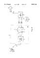
- FIG. 3illustrates a first embodiment of the vehicular repeater system.
- the systemincudes a first radio 58 (radio #1) which serves as an operational radio located within the vehicle 6.
- radio 58can be a squad car radio affixed to the dashboard of a police officer's vehicle used to convey messages to and from the officer while in his vehicle.
- the vehicle car radio 58may comprise any standard radio, such as the radios depicted in the various commonly assigned patents which were mentioned above.
- Radio 58communicates with base station 16 using antenna 60.
- the vehicle 6also includes two additional radio units according to the present invention, identified herein as radio #2 and radio #3. Both of these radios are connected to a passive RF interface 42 and antenna 40. Antenna 40, in turn, communicates with user 12 via his portable radio 14. Radios #2 and #3 are also connected, preferably by hardwired link, to the vehicle radio 58. The radios #2 and #3 provide both analog and digital audio communication to avoid unnecessary digital to analog and analog to digital conversions of audio speech data when messages are routed through the repeater 38. Additionally, control is provided via a controller 56 in association with an interradio digital communication network, which is denoted by the dotted line 54.
- the IVRS unit 38is preferably manufactured as an integrated "black box" unit which may be installed in the trunk of the vehicle 6. Alternatively, the IVRS unit may be installed in the dashboard of the vehicle. As mentioned, the connection between the IVRS unit 38 and the vehicle radio 58 is preferably via hard wired link.
- a primary function of radio #2is to forward information received from base site 16 to portable radio 14.
- radio #2employs a transmitter 50 for transmitting messages received from base site 16 to the portable radio 14 using an operating power balanced for portable operation.
- a primary function of radio #3is to receive messages from portable radio 14, which are then forwarded to the squad car radio 58, and then to base station 16.
- radio #3is shown as only including a receiving section 44 for receiving across the standard portable mobile radio's (e.g. 14) transmit frequency range.
- Radio #2also includes a receiving section 48 with a low power PA (power amplifier) and additional receiver attenuation incorporated within the section denoted schematically as PAD 46 (e.g. attenuator).
- PAD 46e.g. attenuator
- the low power PA and receiver attenuationprevent undesired reception of signals emanating from distant radio units.
- the receiver section 48monitors which frequencies other nearby IVRS units are operating on. To prevent interference, the IVRS unit will not lock onto a control channel which another IVRS unit is already operating on.
- FIG. 4illustrates a second exemplary embodiment of an in-band vehicular repeater system according to the present invention.
- the systemis similar to the first embodiment in its use of an operation vehicle radio 58, which communicates in a typical manner via antenna 60 with base station 16 when the officer 12 is in his vehicle 6.
- an operation vehicle radio 58which communicates in a typical manner via antenna 60 with base station 16 when the officer 12 is in his vehicle 6.
- his portable radio 14may transmit a message to the antenna 40 and associated passive RF interface 42 of IVRS 64.
- Controlis provided by control unit 56 in conjunction with an interradio digital communication network 54.
- Radio #2includes a transmitting section 74 which relays information from the mobile radio 58 to the user's portable radio 14.
- the receiver sectionconsolidates the function of the receiver portions 44 and 46 of the first embodiment shown in FIG. 3.
- the receiver 72includes a primary function of receiving messages from portable radio 14 and relaying the messages to radio base site 16.
- the receiver 72includes low power PA (power amplifier) circuitry and additional receiver attenuation to prevent inadvertent reception of distant IVRS units, which are collectively denoted by the PAD unit (e.g. attenuator) 70.
- PAD unit 70e.g. attenuator
- each portable mobile radiomay include a memory section including a personality profile of the device.
- the personality profileis preferably programmable by the user for use in association with a particular base site or sites.
- the personality profilecontains, among other information, a list of preferred systems on which the device can access base station 16.
- the listranks the systems and their associated control channels according to their suitability.
- the first entry on the listmight contain the control channel identifier for the base station 16 that the portable radio is primarily intended to communicate with.
- the personality profilemay contain channel identifiers associated with other base sites.
- the listmay contain channel identifiers associated with one or more vehicular repeaters (IVRS).
- IVRSvehicular repeaters
- the portablewhen the portable is first turned on it begins by acquiring a control channel (step S2) using the personality profile stored in the memory of the portable radio (e.g. 14).
- the portable radiothen monitors the acquired control channel for requests to transmit or receive messages (step S4).
- the portable radio 14In the absence of a request to transmit or receive a message, the portable radio 14 remains in an idle state locked onto the control channel.
- step S10If the user activates a press-to-talk (PTT) switch on the portable radio, or the base station transmits a message to the user's group of mobiles (e.g. to all narcotics officers), then the control channel is "converted" to a working channel (step S10). The message is transmitted on the working channel, as will be described later in FIGS. 6 and 7. Thereafter, the working channel is "converted" back to a control channel, as described more fully in the above referenced U.S. Pat. No. 5,408,680 to Hattey et al. (step S11)
- PTTpress-to-talk
- the portable radio 14may "lose” its control channel (step S8).
- a control channelmay "deteriorate” because the user moves to a location which the control channel can not provide adequate service.
- the "deterioration" of the control channelmay be gauged from a waning signal strength measure (e.g. RSSI) or the loss of sync on the control channel for a predetermined time period (e.g. five seconds), or the unavailability of a control channel for a prescribed amount of time due to an unusually long call by another portable radio.
- the control channelmay have sufficient strength, yet the portable radio detects that another control channel would provide a superior control channel.
- a superior control channelmight correspond to a stronger signal or a control channel having a higher ranking in the personality profile of the portable unit. If so, the communication system might allow the portable station to switch to that preferred channel.
- the officer 12may begin his investigation in an open field in which his portable radio 14 has sufficient power to reach the base station. Accordingly, the base station will be locked directly onto the control channel of the base site 16. Thereafter, the officer 12 may enter a building to question various individuals, where his portable radio 14 is not successful in transmitting messages to the base site. This will prompt the portable radio to locate another control channel, which may correspond to a nearby vehicular repeater IVRS. However, when the officer leaves the building, the portable radio may once again communicate directly with the base site. The portable would accordingly switch back to the control channel corresponding to the base site.
- the portable radiowill commence scanning for another control channel.
- the portable radio 14will look for available base sites first (step S12) followed by an available IVRS in the area (step S14). If these sites are available, the portable may tune its control channel to these new sites (step S16) and resume monitoring the new control channel for message activity (step S4).
- each IVRS unititself performs a similar control scanning procedure. Namely, each IVRS unit includes its own personality profile storing a list of pre-programmed frequencies on which it may communicate with portable radios. Upon activation of the IVRS by automatic or manual means, the receiver section 48 of the IVRS will monitor each channel contained in its personality profile until it locates one which is not currently in use by another IVRS. If no channel is available, the IVRS will not become active and portables will be forced to communicate with one or more preexisting IVRS units on the scene. The inactive IVRS will, however, continue to search and monitor channels in the event that one should become available.
- the radio communication systemwill attempt to accommodate as many different IVRS units in a given geographic area as possible. This distributes the call traffic to many different IVRS units, and prevents any one IVRS unit from becoming overworked (and consequently depleting its battery supply).
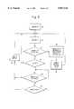
- FIG. 6describes an exemplary protocol by which the portable radios of the present invention may transmit messages to a base site
- FIG. 7describes an exemplary protocol by which the portable radios may receive messages from the base site.
- a channel in the SCAT protocolremains a control channel if no user is presently communicating messages on the channel.
- a userinitiates a communique by depressing a press-to-talk button on his portable radio.
- the portable radiotransmits a request message to the acting base site.
- the acting base sitewill respond by transmitting three channel assignment messages to the portable radio.
- the base sitetransmits three messages as a safeguard to ensure reception of this information by the portable radio.
- the control channelis now an assigned channel.
- the acting base sitewill then transmit a synchronization word followed by a confirmation message.
- the portable radioUpon receiving the confirmation message, the portable radio transmits its audio message (or in general, its data) to the acting base site, coupled with a dotting code preface.
- step S18the user of the portable radio initiates a message transfer by pressing the push-to-talk button of his radio. If the portable radio is currently locked directly onto the base site (as ascertained in step S20), the portable radio will transmit a request for transmission directly to the base site (step S24). The base site will return a channel assignment, thereby converting the control channel into an assigned "working" channel (step S26). The user of the portable radio then proceeds to transmit his audio message (step S28). If the user releases the PTT button (step S30) then the call terminates by transmitting an unkey message (step S32). In a similar manner, the portable radio may receive communication directly from the base site, if within the transmitting range of the base site.
- the portable unitwill start by transmitting a request for transmission to the IVRS unit (step S22). Upon receiving this request, the IVRS transmits an IVRS acknowledgement message to the portable radio (step S23). The IVRS then transmits a request for transmission to the base site 16 (step S34).
- the base sitemay deny assignment (as ascertained in step S37), upon which the IVRS transmits a message to the portable unit notifying the portable unit that the IVRS has been denied an assignment.
- the base sitemay queue the IVRS's request (as determined in step S39), upon which the IVRS queues the calling portable (in step S40). The portable then waits until the IVRS receives an assignment from the base site (step S41). If the IVRS is not informed that its request has been queued (as determined in step S39), it will wait a prescribed amount of time (step S42), after which it will retransmit its request to the base site (in step S34).
- step S46the IVRS transmits a working channel assignment message to the portable radio.
- the userUpon receiving this message, the user proceeds to transmit his audio message via the IVRS unit to the base site (step S48).
- the communiqueis terminated when the user deactivates the PTT switch (step S50), upon which the portable radio transmits an unkey message over the channel (step S52).
- FIG. 7shows an exemplary protocol for receiving messages using the radio communication system according to the present invention.
- a portable unitupon logging into an IVRS, a portable unit provides its logical ID (LID) and talk group ID which it is monitoring (GID). The IVRS stores this ID information to form a list of all portable LIDs and GIDs associated with the IVRS unit.
- the IVRSconsults this list to determine whether the call is addressed to any associated portable(s) (steps S66 and S68). If so, the IVRS unit instructs the addressed portable radios to unmute their audio (step S70 and S72) to receive the call.
- the portable unitsare instructed to again mute their radios (steps S74 and S76), upon which the portables and IVRS monitor their respective control channels for further calls (step S4 of FIG. 5).
- the portable unitstransmit a login message whenever switching to an IVRS site. In other embodiments, the portable units may additionally transmit a login message whenever the portable units change to a new talk group.
- the portable radiomay transmit a logout message when leaving an IVRS.
- the IVRSautomatically removes inactive LIDs and GIDs from its list after a prescribed time-out period.
- the IVRS unitrequests inactive portables to re-login after a prescribed period. The third embodiment allows infrequently used portables to maintain their LIDs and GIDs on the IVRS list; only those portables which do not re-login will be dropped.
- the portable unitscommunicate with the IVRS repeater in much the same manner as they communicate with the SCAT base station.
- the IVRS unitsmay be conceptualized as a portable base station.
- This analogymay be extended by actually eliminating the radio #1 illustrated in FIGS. 3 and 4, and using the vehicular repeater as a stand-alone portable base site.
- a base stationcould be readily transported to remote areas which are out of range of fixed base stations. This may be used to provide radio communication services to support disaster relief activities in remote areas.
- the portable base stationcould be transported to an area to supplement a pre-existing radio communication system, and thereby alleviate the processing load of the pre-existing radio communication system.
- Further details regarding the use of IVRS technology as a stand-alone portable base stationmay be found in commonly assigned U.S. application Ser. No. (our reference no. 027575-005), entitled “Deployable Single Channel Autonomous Trunked Communications System", Ser. No. 08/705,553.
Landscapes
- Engineering & Computer Science (AREA)
- Computer Networks & Wireless Communication (AREA)
- Signal Processing (AREA)
- Mobile Radio Communication Systems (AREA)
Abstract
Description
Claims (22)
Priority Applications (3)
| Application Number | Priority Date | Filing Date | Title |
|---|---|---|---|
| US08/694,745US5857144A (en) | 1996-08-09 | 1996-08-09 | In-band vehicular repeater for trunked radio system |
| AU42295/97AAU4229597A (en) | 1996-08-09 | 1997-08-01 | In-band vehicular repeater for trunked radio system |
| PCT/US1997/013376WO1998007286A2 (en) | 1996-08-09 | 1997-08-01 | In-band vehicular repeater for trunked radio system |
Applications Claiming Priority (1)
| Application Number | Priority Date | Filing Date | Title |
|---|---|---|---|
| US08/694,745US5857144A (en) | 1996-08-09 | 1996-08-09 | In-band vehicular repeater for trunked radio system |
Publications (1)
| Publication Number | Publication Date |
|---|---|
| US5857144Atrue US5857144A (en) | 1999-01-05 |
Family
ID=24790106
Family Applications (1)
| Application Number | Title | Priority Date | Filing Date |
|---|---|---|---|
| US08/694,745Expired - LifetimeUS5857144A (en) | 1996-08-09 | 1996-08-09 | In-band vehicular repeater for trunked radio system |
Country Status (3)
| Country | Link |
|---|---|
| US (1) | US5857144A (en) |
| AU (1) | AU4229597A (en) |
| WO (1) | WO1998007286A2 (en) |
Cited By (54)
| Publication number | Priority date | Publication date | Assignee | Title |
|---|---|---|---|---|
| US6141533A (en)* | 1997-11-13 | 2000-10-31 | Motorola, Inc. | Method and apparatus for a mobile repeater |
| US6151493A (en)* | 1997-09-04 | 2000-11-21 | Miyaken Co., Ltd. | Device for prohibiting unauthorized use of electronic devices |
| US6198924B1 (en)* | 1996-08-14 | 2001-03-06 | Nec Corporation | Frequency channel selection method for radio communication system |
| US6445687B1 (en)* | 1997-06-09 | 2002-09-03 | Nec Corporation | Group communication system |
| WO2002095968A1 (en)* | 2001-05-22 | 2002-11-28 | Armando Ruiz | A two unit portable cellular phone system |
| US6532224B1 (en)* | 1999-05-10 | 2003-03-11 | Ericsson, Inc. | Method, systems, and terminals for assigning control channel time slots for group and individual pages |
| US6542494B1 (en)* | 1998-09-11 | 2003-04-01 | Sony Corporation | Communication control method and transmission apparatus |
| US6564049B1 (en) | 1999-05-10 | 2003-05-13 | Ericsson Inc. | Methods and systems for providing group calls with reduced setup times |
| US20030097581A1 (en)* | 2001-09-28 | 2003-05-22 | Zimmer Vincent J. | Technique to support co-location and certification of executable content from a pre-boot space into an operating system runtime environment |
| US6574452B1 (en)* | 1998-07-28 | 2003-06-03 | Canon Kabushiki Kaisha | Method and device for communication on a network |
| US6577874B1 (en) | 1999-05-10 | 2003-06-10 | Ericsson Inc. | Methods and systems for providing temporary identification numbers for mobile terminals |
| US6580704B1 (en)* | 1999-08-26 | 2003-06-17 | Nokia Corporation | Direct mode communication method between two mobile terminals in access point controlled wireless LAN systems |
| US20030134633A1 (en)* | 2002-01-11 | 2003-07-17 | Reid Jeffrey Turner | Scanning tone remote adapter for land-mobile radio dispatch for use with dispersed dispatch stations |
| US6647244B1 (en)* | 1999-11-16 | 2003-11-11 | The Whitaker Corporation | Wireless vehicular repeater system |
| US6768897B1 (en)* | 1997-09-30 | 2004-07-27 | Nokia Networks Oy | Method of adjusting frequency of cellular radio repeater |
| US6785511B1 (en)* | 2000-10-25 | 2004-08-31 | Tyco Electronics Corporation | Wireless vehicular repeater system |
| US20040203978A1 (en)* | 2002-09-17 | 2004-10-14 | Wong Chin Pan | Bridging talk group in communication systems |
| US20040224631A1 (en)* | 2003-05-08 | 2004-11-11 | M/A Com. Inc. | Activiation method for wireless communication system |
| US20050208928A1 (en)* | 2002-06-21 | 2005-09-22 | Koninklijke Philips Electronics N.V. | Communication system with an extended coverage area |
| US20060056352A1 (en)* | 2002-11-15 | 2006-03-16 | Widefi, Inc. | Wireless local area network repeater with detection |
| US20060063484A1 (en)* | 2002-10-24 | 2006-03-23 | Proctor James A Jr | Wireless local area network repeater with in-band control channel |
| US20060063485A1 (en)* | 2002-10-15 | 2006-03-23 | Gainey Kenneth M | Wireless local area network repeater with automatic gain control for extending network coverage |
| US20060098592A1 (en)* | 2002-12-16 | 2006-05-11 | Widefi, Inc. | Wireless network repeater |
| US20060193271A1 (en)* | 2005-01-28 | 2006-08-31 | Widefi, Inc. | Physical layer repeater configuration for increasing MIMO performance |
| US20060240769A1 (en)* | 2004-04-06 | 2006-10-26 | Proctor Jr James A | Transmission canceller for wireless local area network |
| US20070032192A1 (en)* | 2004-06-03 | 2007-02-08 | Widefi, Inc. | Frequency translating repeater with low cost high performance local oscillator architecture |
| US7181160B2 (en) | 1997-09-17 | 2007-02-20 | Aerosat Corporation | Method and apparatus for providing a signal to passengers of a passenger vehicle |
| US7206294B2 (en)* | 2001-08-15 | 2007-04-17 | Meshnetworks, Inc. | Movable access points and repeaters for minimizing coverage and capacity constraints in a wireless communications network and a method for using the same |
| US7251223B1 (en)* | 2000-09-27 | 2007-07-31 | Aerosat Corporation | Low-height, low-cost, high-gain antenna and system for mobile platforms |
| US20070252708A1 (en)* | 2004-01-19 | 2007-11-01 | Kabushiki Kaisha Eighting | Human Body Monitoring System |
| US20080003942A1 (en)* | 2006-06-30 | 2008-01-03 | Motorola, Inc. | Method and system for communicating within a communication network |
| US20080077973A1 (en)* | 2006-09-21 | 2008-03-27 | Zimmer Vincent J | High integrity firmware |
| US20080207241A1 (en)* | 2007-02-28 | 2008-08-28 | Motorola, Inc. | Method and system for distributing talk group activity among multiple vehicle repeaters |
| US20090092045A1 (en)* | 2006-05-18 | 2009-04-09 | Huawei Technologies Co., Ltd. | Method And System For Network Logout For A Mobile Station In Idle Mode |
| US20090129442A1 (en)* | 2007-10-11 | 2009-05-21 | Mohebbi Behzad B | Cdma unii link |
| US20090247070A1 (en)* | 2006-07-18 | 2009-10-01 | Motorola, Inc. | Wireless communication system, portable radio repeater and magazine therefor |
| US20090290526A1 (en)* | 2006-09-21 | 2009-11-26 | Qualcomm Incorporated | Method and apparatus for mitigating oscillation between repeaters |
| US20100002620A1 (en)* | 2006-09-01 | 2010-01-07 | Qualcomm Incorporated | Repeater having dual receiver or transmitter antenna configuration with adaptation for increased isolation |
| US20100159824A1 (en)* | 2008-12-23 | 2010-06-24 | Paul Goodjohn | System and method for controlling a mobile repeater |
| US20100279647A1 (en)* | 2009-05-01 | 2010-11-04 | At&T Intellectual Property I, L.P. | Methods and systems for relaying out of range emergency information |
| US20100325388A1 (en)* | 2009-06-17 | 2010-12-23 | Massively Parallel Technologies, Inc. | Multi-Core Parallel Processing System |
| US20110051630A1 (en)* | 2009-08-31 | 2011-03-03 | Tait Electronics Limited | Repeater for a trunked radio network |
| US20110063105A1 (en)* | 2009-09-16 | 2011-03-17 | Broadcom Corporation | Emergency message relay |
| US8023885B2 (en) | 2004-05-13 | 2011-09-20 | Qualcomm Incorporated | Non-frequency translating repeater with downlink detection for uplink and downlink synchronization |
| US8078100B2 (en) | 2002-10-15 | 2011-12-13 | Qualcomm Incorporated | Physical layer repeater with discrete time filter for all-digital detection and delay generation |
| US8089913B2 (en) | 2002-10-24 | 2012-01-03 | Qualcomm Incorporated | Physical layer repeater with selective use of higher layer functions based on network operating conditions |
| US20120034902A1 (en)* | 2009-03-19 | 2012-02-09 | Abirami Rajendran | Uninterrupted usage and access of physically unreachable handheld device |
| US8122134B2 (en) | 2002-10-11 | 2012-02-21 | Qualcomm Incorporated | Reducing loop effects in a wireless local area network repeater |
| US8498234B2 (en) | 2002-06-21 | 2013-07-30 | Qualcomm Incorporated | Wireless local area network repeater |
| KR101302518B1 (en)* | 2011-03-24 | 2013-09-03 | (주)남경텔레콤 | Mobile-Type Relay Station System for TRS |
| US8774079B2 (en) | 2006-10-26 | 2014-07-08 | Qualcomm Incorporated | Repeater techniques for multiple input multiple output utilizing beam formers |
| US8885688B2 (en) | 2002-10-01 | 2014-11-11 | Qualcomm Incorporated | Control message management in physical layer repeater |
| US20170142559A1 (en)* | 2015-04-24 | 2017-05-18 | Motorola Solutions, Inc. | Aggregating and segregating multiple digital vehicular repeaters automatically |
| US9848311B1 (en)* | 2014-08-01 | 2017-12-19 | Catalyst Communications Technologies | System and method for managing communications |
Citations (31)
| Publication number | Priority date | Publication date | Assignee | Title |
|---|---|---|---|---|
| US3955140A (en)* | 1975-05-20 | 1976-05-04 | Public Systems, Inc. | Mobile radio extension unit with punch through operation |
| US4056780A (en)* | 1975-06-25 | 1977-11-01 | Motorola, Inc. | Vehicle repeater prioritization system |
| US4056779A (en)* | 1976-04-05 | 1977-11-01 | Motorola, Inc. | Vehicular repeater |
| US4150334A (en)* | 1977-10-12 | 1979-04-17 | General Electric Company | Control circuit for a radio repeater |
| US4383332A (en)* | 1980-11-21 | 1983-05-10 | Bell Telephone Laboratories, Incorporated | High capacity digital mobile radio system |
| US4539706A (en)* | 1983-02-03 | 1985-09-03 | General Electric Company | Mobile vehicular repeater system which provides up-link acknowledgement signal to portable transceiver at end of transceiver transmission |
| US4553262A (en)* | 1983-11-25 | 1985-11-12 | Motorola, Inc. | Communications system enabling radio link access for non-trunked radio units to a multifrequency trunked two-way communications systems |
| US4553272A (en)* | 1981-02-26 | 1985-11-19 | University Of Pittsburgh | Regeneration of living tissues by growth of isolated cells in porous implant and product thereof |
| DE3528886A1 (en)* | 1985-08-12 | 1987-02-19 | Siemens Ag | Radiotelephony system |
| US4659878A (en)* | 1985-09-11 | 1987-04-21 | General Electric Company | Method and apparatus for interference free communications between a remote handset and a host subscriber unit in a Cellular Radio Telephone System |
| US4771448A (en)* | 1986-11-18 | 1988-09-13 | Northern Telecom Limited | Private cellular system |
| US4905302A (en)* | 1987-06-03 | 1990-02-27 | General Electric Company | Trunked radio repeater system |
| US4939746A (en)* | 1987-06-03 | 1990-07-03 | General Electric Company | Trunked radio repeater system |
| US4965787A (en)* | 1989-02-09 | 1990-10-23 | Data General Corporation | Methods and apparatus for multiplexing sub-rate channels in a digital data communication system |
| US5010583A (en)* | 1989-10-02 | 1991-04-23 | Motorola, Inc. | Repeater for a wide area coverage system |
| US5056152A (en)* | 1988-02-08 | 1991-10-08 | Motorola, Inc. | Dual level prioritized vehicular repeater system |
| US5109526A (en)* | 1989-12-18 | 1992-04-28 | Motorola, Inc. | Vehicular repeater system |
| US5175866A (en)* | 1987-06-03 | 1992-12-29 | Ericcson Ge Mobile Communications Inc. | Fail-soft architecture for public trunking system |
| US5276686A (en)* | 1990-10-17 | 1994-01-04 | Kabushiki Kaisha Toshiba | Mobile radio communication system having mobile base and portable devices as a mobile station |
| US5355511A (en)* | 1990-08-08 | 1994-10-11 | Aisin Seiki Kabushiki Kaisha | Position monitoring for communicable and uncommunicable mobile stations |
| US5408680A (en)* | 1992-08-11 | 1995-04-18 | Ericsson Ge Mobile Communications Inc. | Single channel autonomous digitally trunked RF communications system |
| US5425030A (en)* | 1990-06-29 | 1995-06-13 | Motorola Inc. | On-site system frequency sharing with trunking system |
| US5428817A (en)* | 1992-06-09 | 1995-06-27 | Nec Corporation | Mobile communication system having variable coverage areas |
| US5430789A (en)* | 1992-11-04 | 1995-07-04 | Nec Corporation | Cellular mobile base station apparatus for serving a first and second cell zones |
| US5487185A (en)* | 1992-02-24 | 1996-01-23 | Nokia Telecommunications Oy | Method for extending mean time between failures of transmitters used in a cellular system, by intermittently shifting among them which is transmitting a control channel versus which is transmitting a traffic carrier |
| US5490284A (en)* | 1993-05-27 | 1996-02-06 | Kokusai Denshin Denwa Kabushiki Kaisha | Satellite/land mobile communication system integration scheme |
| US5519761A (en)* | 1994-07-08 | 1996-05-21 | Qualcomm Incorporated | Airborne radiotelephone communications system |
| US5533029A (en)* | 1993-11-12 | 1996-07-02 | Pacific Communication Sciences, Inc. | Cellular digital packet data mobile data base station |
| US5548809A (en)* | 1992-07-15 | 1996-08-20 | Southwestern Bell Technology Resources, Inc. | Spectrum sharing communications system and system for monitoring available spectrum |
| GB2298998A (en)* | 1995-03-17 | 1996-09-18 | Rover Group | Mobile telephone transceiver for a motor vehicle; same frequency relay |
| US5666661A (en)* | 1994-03-10 | 1997-09-09 | Motorola, Inc. | Method for automatically bypassing the use of a communication system infrastructure |
- 1996
- 1996-08-09USUS08/694,745patent/US5857144A/ennot_activeExpired - Lifetime
- 1997
- 1997-08-01WOPCT/US1997/013376patent/WO1998007286A2/enactiveApplication Filing
- 1997-08-01AUAU42295/97Apatent/AU4229597A/ennot_activeAbandoned
Patent Citations (31)
| Publication number | Priority date | Publication date | Assignee | Title |
|---|---|---|---|---|
| US3955140A (en)* | 1975-05-20 | 1976-05-04 | Public Systems, Inc. | Mobile radio extension unit with punch through operation |
| US4056780A (en)* | 1975-06-25 | 1977-11-01 | Motorola, Inc. | Vehicle repeater prioritization system |
| US4056779A (en)* | 1976-04-05 | 1977-11-01 | Motorola, Inc. | Vehicular repeater |
| US4150334A (en)* | 1977-10-12 | 1979-04-17 | General Electric Company | Control circuit for a radio repeater |
| US4383332A (en)* | 1980-11-21 | 1983-05-10 | Bell Telephone Laboratories, Incorporated | High capacity digital mobile radio system |
| US4553272A (en)* | 1981-02-26 | 1985-11-19 | University Of Pittsburgh | Regeneration of living tissues by growth of isolated cells in porous implant and product thereof |
| US4539706A (en)* | 1983-02-03 | 1985-09-03 | General Electric Company | Mobile vehicular repeater system which provides up-link acknowledgement signal to portable transceiver at end of transceiver transmission |
| US4553262A (en)* | 1983-11-25 | 1985-11-12 | Motorola, Inc. | Communications system enabling radio link access for non-trunked radio units to a multifrequency trunked two-way communications systems |
| DE3528886A1 (en)* | 1985-08-12 | 1987-02-19 | Siemens Ag | Radiotelephony system |
| US4659878A (en)* | 1985-09-11 | 1987-04-21 | General Electric Company | Method and apparatus for interference free communications between a remote handset and a host subscriber unit in a Cellular Radio Telephone System |
| US4771448A (en)* | 1986-11-18 | 1988-09-13 | Northern Telecom Limited | Private cellular system |
| US4905302A (en)* | 1987-06-03 | 1990-02-27 | General Electric Company | Trunked radio repeater system |
| US4939746A (en)* | 1987-06-03 | 1990-07-03 | General Electric Company | Trunked radio repeater system |
| US5175866A (en)* | 1987-06-03 | 1992-12-29 | Ericcson Ge Mobile Communications Inc. | Fail-soft architecture for public trunking system |
| US5056152A (en)* | 1988-02-08 | 1991-10-08 | Motorola, Inc. | Dual level prioritized vehicular repeater system |
| US4965787A (en)* | 1989-02-09 | 1990-10-23 | Data General Corporation | Methods and apparatus for multiplexing sub-rate channels in a digital data communication system |
| US5010583A (en)* | 1989-10-02 | 1991-04-23 | Motorola, Inc. | Repeater for a wide area coverage system |
| US5109526A (en)* | 1989-12-18 | 1992-04-28 | Motorola, Inc. | Vehicular repeater system |
| US5425030A (en)* | 1990-06-29 | 1995-06-13 | Motorola Inc. | On-site system frequency sharing with trunking system |
| US5355511A (en)* | 1990-08-08 | 1994-10-11 | Aisin Seiki Kabushiki Kaisha | Position monitoring for communicable and uncommunicable mobile stations |
| US5276686A (en)* | 1990-10-17 | 1994-01-04 | Kabushiki Kaisha Toshiba | Mobile radio communication system having mobile base and portable devices as a mobile station |
| US5487185A (en)* | 1992-02-24 | 1996-01-23 | Nokia Telecommunications Oy | Method for extending mean time between failures of transmitters used in a cellular system, by intermittently shifting among them which is transmitting a control channel versus which is transmitting a traffic carrier |
| US5428817A (en)* | 1992-06-09 | 1995-06-27 | Nec Corporation | Mobile communication system having variable coverage areas |
| US5548809A (en)* | 1992-07-15 | 1996-08-20 | Southwestern Bell Technology Resources, Inc. | Spectrum sharing communications system and system for monitoring available spectrum |
| US5408680A (en)* | 1992-08-11 | 1995-04-18 | Ericsson Ge Mobile Communications Inc. | Single channel autonomous digitally trunked RF communications system |
| US5430789A (en)* | 1992-11-04 | 1995-07-04 | Nec Corporation | Cellular mobile base station apparatus for serving a first and second cell zones |
| US5490284A (en)* | 1993-05-27 | 1996-02-06 | Kokusai Denshin Denwa Kabushiki Kaisha | Satellite/land mobile communication system integration scheme |
| US5533029A (en)* | 1993-11-12 | 1996-07-02 | Pacific Communication Sciences, Inc. | Cellular digital packet data mobile data base station |
| US5666661A (en)* | 1994-03-10 | 1997-09-09 | Motorola, Inc. | Method for automatically bypassing the use of a communication system infrastructure |
| US5519761A (en)* | 1994-07-08 | 1996-05-21 | Qualcomm Incorporated | Airborne radiotelephone communications system |
| GB2298998A (en)* | 1995-03-17 | 1996-09-18 | Rover Group | Mobile telephone transceiver for a motor vehicle; same frequency relay |
Cited By (82)
| Publication number | Priority date | Publication date | Assignee | Title |
|---|---|---|---|---|
| US6198924B1 (en)* | 1996-08-14 | 2001-03-06 | Nec Corporation | Frequency channel selection method for radio communication system |
| US6445687B1 (en)* | 1997-06-09 | 2002-09-03 | Nec Corporation | Group communication system |
| US6151493A (en)* | 1997-09-04 | 2000-11-21 | Miyaken Co., Ltd. | Device for prohibiting unauthorized use of electronic devices |
| US7181160B2 (en) | 1997-09-17 | 2007-02-20 | Aerosat Corporation | Method and apparatus for providing a signal to passengers of a passenger vehicle |
| US6768897B1 (en)* | 1997-09-30 | 2004-07-27 | Nokia Networks Oy | Method of adjusting frequency of cellular radio repeater |
| US6141533A (en)* | 1997-11-13 | 2000-10-31 | Motorola, Inc. | Method and apparatus for a mobile repeater |
| US6574452B1 (en)* | 1998-07-28 | 2003-06-03 | Canon Kabushiki Kaisha | Method and device for communication on a network |
| US6542494B1 (en)* | 1998-09-11 | 2003-04-01 | Sony Corporation | Communication control method and transmission apparatus |
| US6564049B1 (en) | 1999-05-10 | 2003-05-13 | Ericsson Inc. | Methods and systems for providing group calls with reduced setup times |
| US6577874B1 (en) | 1999-05-10 | 2003-06-10 | Ericsson Inc. | Methods and systems for providing temporary identification numbers for mobile terminals |
| US6532224B1 (en)* | 1999-05-10 | 2003-03-11 | Ericsson, Inc. | Method, systems, and terminals for assigning control channel time slots for group and individual pages |
| US6580704B1 (en)* | 1999-08-26 | 2003-06-17 | Nokia Corporation | Direct mode communication method between two mobile terminals in access point controlled wireless LAN systems |
| US6647244B1 (en)* | 1999-11-16 | 2003-11-11 | The Whitaker Corporation | Wireless vehicular repeater system |
| US7251223B1 (en)* | 2000-09-27 | 2007-07-31 | Aerosat Corporation | Low-height, low-cost, high-gain antenna and system for mobile platforms |
| KR100795279B1 (en) | 2000-10-25 | 2008-01-15 | 타이코 일렉트로닉스 코포레이션 | Car wireless relay system |
| US6785511B1 (en)* | 2000-10-25 | 2004-08-31 | Tyco Electronics Corporation | Wireless vehicular repeater system |
| WO2002095968A1 (en)* | 2001-05-22 | 2002-11-28 | Armando Ruiz | A two unit portable cellular phone system |
| US7206294B2 (en)* | 2001-08-15 | 2007-04-17 | Meshnetworks, Inc. | Movable access points and repeaters for minimizing coverage and capacity constraints in a wireless communications network and a method for using the same |
| US6978018B2 (en)* | 2001-09-28 | 2005-12-20 | Intel Corporation | Technique to support co-location and certification of executable content from a pre-boot space into an operating system runtime environment |
| US20030097581A1 (en)* | 2001-09-28 | 2003-05-22 | Zimmer Vincent J. | Technique to support co-location and certification of executable content from a pre-boot space into an operating system runtime environment |
| US6950653B2 (en)* | 2002-01-11 | 2005-09-27 | Hubbell Incorporated | Scanning tone remote adapter for land-mobile radio dispatch for use with dispersed dispatch stations |
| US20030134633A1 (en)* | 2002-01-11 | 2003-07-17 | Reid Jeffrey Turner | Scanning tone remote adapter for land-mobile radio dispatch for use with dispersed dispatch stations |
| US20050208928A1 (en)* | 2002-06-21 | 2005-09-22 | Koninklijke Philips Electronics N.V. | Communication system with an extended coverage area |
| US8498234B2 (en) | 2002-06-21 | 2013-07-30 | Qualcomm Incorporated | Wireless local area network repeater |
| US7181234B2 (en)* | 2002-09-17 | 2007-02-20 | Motorola, Inc. | Method and apparatus for bridging talk groups in public/private communication systems |
| US20040203978A1 (en)* | 2002-09-17 | 2004-10-14 | Wong Chin Pan | Bridging talk group in communication systems |
| US8885688B2 (en) | 2002-10-01 | 2014-11-11 | Qualcomm Incorporated | Control message management in physical layer repeater |
| US8122134B2 (en) | 2002-10-11 | 2012-02-21 | Qualcomm Incorporated | Reducing loop effects in a wireless local area network repeater |
| US8060009B2 (en) | 2002-10-15 | 2011-11-15 | Qualcomm Incorporated | Wireless local area network repeater with automatic gain control for extending network coverage |
| US8078100B2 (en) | 2002-10-15 | 2011-12-13 | Qualcomm Incorporated | Physical layer repeater with discrete time filter for all-digital detection and delay generation |
| US20060063485A1 (en)* | 2002-10-15 | 2006-03-23 | Gainey Kenneth M | Wireless local area network repeater with automatic gain control for extending network coverage |
| US8089913B2 (en) | 2002-10-24 | 2012-01-03 | Qualcomm Incorporated | Physical layer repeater with selective use of higher layer functions based on network operating conditions |
| US20060063484A1 (en)* | 2002-10-24 | 2006-03-23 | Proctor James A Jr | Wireless local area network repeater with in-band control channel |
| US20060056352A1 (en)* | 2002-11-15 | 2006-03-16 | Widefi, Inc. | Wireless local area network repeater with detection |
| US8111645B2 (en) | 2002-11-15 | 2012-02-07 | Qualcomm Incorporated | Wireless local area network repeater with detection |
| US7990904B2 (en) | 2002-12-16 | 2011-08-02 | Qualcomm Incorporated | Wireless network repeater |
| US20060098592A1 (en)* | 2002-12-16 | 2006-05-11 | Widefi, Inc. | Wireless network repeater |
| US20040224631A1 (en)* | 2003-05-08 | 2004-11-11 | M/A Com. Inc. | Activiation method for wireless communication system |
| CN100551151C (en)* | 2003-05-08 | 2009-10-14 | M/A-Com公司 | Activation method of wireless communication system |
| US7313363B2 (en)* | 2003-05-08 | 2007-12-25 | M/A-Com, Inc. | Activation method for wireless communication system |
| US20070252708A1 (en)* | 2004-01-19 | 2007-11-01 | Kabushiki Kaisha Eighting | Human Body Monitoring System |
| US7342491B2 (en)* | 2004-01-19 | 2008-03-11 | Kabushiki Kaisha Eighting | Human body monitoring system |
| US20060240769A1 (en)* | 2004-04-06 | 2006-10-26 | Proctor Jr James A | Transmission canceller for wireless local area network |
| US8027642B2 (en)* | 2004-04-06 | 2011-09-27 | Qualcomm Incorporated | Transmission canceller for wireless local area network |
| US8023885B2 (en) | 2004-05-13 | 2011-09-20 | Qualcomm Incorporated | Non-frequency translating repeater with downlink detection for uplink and downlink synchronization |
| US20070032192A1 (en)* | 2004-06-03 | 2007-02-08 | Widefi, Inc. | Frequency translating repeater with low cost high performance local oscillator architecture |
| US8095067B2 (en) | 2004-06-03 | 2012-01-10 | Qualcomm Incorporated | Frequency translating repeater with low cost high performance local oscillator architecture |
| US20060193271A1 (en)* | 2005-01-28 | 2006-08-31 | Widefi, Inc. | Physical layer repeater configuration for increasing MIMO performance |
| US8059727B2 (en) | 2005-01-28 | 2011-11-15 | Qualcomm Incorporated | Physical layer repeater configuration for increasing MIMO performance |
| US8914005B2 (en) | 2006-03-23 | 2014-12-16 | Huawei Technologies Co., Ltd. | Method and system for network logout of a mobile station in idle mode |
| US8238908B2 (en)* | 2006-05-18 | 2012-08-07 | Huawei Technologies Co., Ltd. | Method and system for network logout for a mobile station in idle mode |
| US20090092045A1 (en)* | 2006-05-18 | 2009-04-09 | Huawei Technologies Co., Ltd. | Method And System For Network Logout For A Mobile Station In Idle Mode |
| AU2007269514B2 (en)* | 2006-06-30 | 2011-03-10 | Motorola Solutions, Inc. | Method and system for communicating within a communication network |
| US20080003942A1 (en)* | 2006-06-30 | 2008-01-03 | Motorola, Inc. | Method and system for communicating within a communication network |
| US7711383B2 (en)* | 2006-06-30 | 2010-05-04 | Motorola, Inc. | Method and system for communicating within a communication network |
| US8019278B2 (en)* | 2006-07-18 | 2011-09-13 | Motorola Solutions, Inc. | Wireless communication system, portable radio repeater and magazine therefor |
| US20090247070A1 (en)* | 2006-07-18 | 2009-10-01 | Motorola, Inc. | Wireless communication system, portable radio repeater and magazine therefor |
| US20100002620A1 (en)* | 2006-09-01 | 2010-01-07 | Qualcomm Incorporated | Repeater having dual receiver or transmitter antenna configuration with adaptation for increased isolation |
| US20090290526A1 (en)* | 2006-09-21 | 2009-11-26 | Qualcomm Incorporated | Method and apparatus for mitigating oscillation between repeaters |
| US20080077973A1 (en)* | 2006-09-21 | 2008-03-27 | Zimmer Vincent J | High integrity firmware |
| US8559379B2 (en) | 2006-09-21 | 2013-10-15 | Qualcomm Incorporated | Method and apparatus for mitigating oscillation between repeaters |
| US8312509B2 (en)* | 2006-09-21 | 2012-11-13 | Intel Corporation | High integrity firmware |
| US8774079B2 (en) | 2006-10-26 | 2014-07-08 | Qualcomm Incorporated | Repeater techniques for multiple input multiple output utilizing beam formers |
| US7711319B2 (en)* | 2007-02-28 | 2010-05-04 | Motorola, Inc. | Method and system for distributing talk group activity among multiple vehicle repeaters |
| US20080207241A1 (en)* | 2007-02-28 | 2008-08-28 | Motorola, Inc. | Method and system for distributing talk group activity among multiple vehicle repeaters |
| US8351366B2 (en)* | 2007-10-11 | 2013-01-08 | Nextivity, Inc. | CDMA UNII link |
| US20090129442A1 (en)* | 2007-10-11 | 2009-05-21 | Mohebbi Behzad B | Cdma unii link |
| US8180281B2 (en)* | 2008-12-23 | 2012-05-15 | Pine Valley Investments, Inc. | System and method for controlling a mobile repeater |
| US20100159824A1 (en)* | 2008-12-23 | 2010-06-24 | Paul Goodjohn | System and method for controlling a mobile repeater |
| US8428571B2 (en)* | 2009-03-19 | 2013-04-23 | Novell, Inc. | Uninterrupted usage and access of physically unreachable handheld device |
| US20120034902A1 (en)* | 2009-03-19 | 2012-02-09 | Abirami Rajendran | Uninterrupted usage and access of physically unreachable handheld device |
| US8406729B2 (en) | 2009-05-01 | 2013-03-26 | At&T Intellectual Property I, L.P. | Methods and systems for relaying out of range emergency information |
| US8208891B2 (en)* | 2009-05-01 | 2012-06-26 | At&T Intellectual Property I, L.P. | Methods and systems for relaying out of range emergency information |
| US8660480B2 (en) | 2009-05-01 | 2014-02-25 | At&T Intellectual Property I, L.P. | Methods and systems for relaying out of range emergency information |
| US20100279647A1 (en)* | 2009-05-01 | 2010-11-04 | At&T Intellectual Property I, L.P. | Methods and systems for relaying out of range emergency information |
| US20100325388A1 (en)* | 2009-06-17 | 2010-12-23 | Massively Parallel Technologies, Inc. | Multi-Core Parallel Processing System |
| US20110051630A1 (en)* | 2009-08-31 | 2011-03-03 | Tait Electronics Limited | Repeater for a trunked radio network |
| US20110063105A1 (en)* | 2009-09-16 | 2011-03-17 | Broadcom Corporation | Emergency message relay |
| KR101302518B1 (en)* | 2011-03-24 | 2013-09-03 | (주)남경텔레콤 | Mobile-Type Relay Station System for TRS |
| US9848311B1 (en)* | 2014-08-01 | 2017-12-19 | Catalyst Communications Technologies | System and method for managing communications |
| US20170142559A1 (en)* | 2015-04-24 | 2017-05-18 | Motorola Solutions, Inc. | Aggregating and segregating multiple digital vehicular repeaters automatically |
| US9967718B2 (en)* | 2015-04-24 | 2018-05-08 | Motorola Solutions, Inc. | Aggregating and segregating multiple digital vehicular repeaters automatically |
Also Published As
| Publication number | Publication date |
|---|---|
| AU4229597A (en) | 1998-03-06 |
| WO1998007286A2 (en) | 1998-02-19 |
| WO1998007286A3 (en) | 1998-05-07 |
Similar Documents
| Publication | Publication Date | Title |
|---|---|---|
| US5857144A (en) | In-band vehicular repeater for trunked radio system | |
| US6047160A (en) | Transportable base station for a trunked radio communication system | |
| US5003619A (en) | Method and apparatus for adjusting the power of a transmitter | |
| US5214789A (en) | Radio channel allocation based on location of mobile users | |
| US5179721A (en) | Method for inter operation of a cellular communication system and a trunking communication system | |
| KR100325259B1 (en) | Cellular Wireless Systems and Mobile Wireless Devices | |
| JP4039844B2 (en) | Communication network and communication method | |
| US6301263B1 (en) | Method and apparatus for providing fair access in a group communication system in which users experience differing signaling delays | |
| US5274699A (en) | Method for providing caller identification to a call recipient | |
| US6985716B2 (en) | Radio signal broadcast system and method | |
| US5343493A (en) | Personal assistance system and method for use with a cellular communication system | |
| US6161016A (en) | Broadcast channel seizure with allocated single traffic channel per occupied cell in a cellular system | |
| US4817190A (en) | Method for dynamically regrouping subscribers on a communications system | |
| US5526376A (en) | Intelligent repeater interface | |
| US7711319B2 (en) | Method and system for distributing talk group activity among multiple vehicle repeaters | |
| US20020019222A1 (en) | Automatic radio wave output limiting system for portable telephone set | |
| US6804529B1 (en) | Trunked radio repeater communication system including home channel aliasing and call grouping | |
| JPS647706B2 (en) | ||
| JPH06181454A (en) | Radiotelephone/satellite mobile system | |
| JPH10500815A (en) | Method for establishing a call in a mobile communication system | |
| JP3180346B2 (en) | Single channel remote station relay method | |
| US5758283A (en) | Method and apparatus for locating mobile radio units in a multisite radio system | |
| KR20070026778A (en) | Communication unit, cellular communication system and method of operation thereof | |
| AU2012388821A1 (en) | Mobile communication method using a movable relay station | |
| KR100275388B1 (en) | Method for preventing illigal usage of a cellular phone |
Legal Events
| Date | Code | Title | Description |
|---|---|---|---|
| AS | Assignment | Owner name:ERICSSON INC., NORTH CAROLINA Free format text:ASSIGNMENT OF ASSIGNORS INTEREST;ASSIGNORS:MANGUM, PETER M.;BUTLER, CLYDE R., JR.;DREON, STEVEN T.;AND OTHERS;REEL/FRAME:008184/0930 Effective date:19960807 | |
| FEPP | Fee payment procedure | Free format text:PAYOR NUMBER ASSIGNED (ORIGINAL EVENT CODE: ASPN); ENTITY STATUS OF PATENT OWNER: LARGE ENTITY | |
| STCF | Information on status: patent grant | Free format text:PATENTED CASE | |
| AS | Assignment | Owner name:PNC BANK, NATIONAL ASSOCIATION, PENNSYLVANIA Free format text:SECURITY INTEREST;ASSIGNOR:COM-NET ERICSSON CRITICAL RADIO SYSTEMS, INC.;REEL/FRAME:010557/0001 Effective date:20000126 | |
| AS | Assignment | Owner name:COM-NET ERICSSON CRITICAL RADIO SYSTEMS, INC., PEN Free format text:ASSIGNMENT OF ASSIGNORS INTEREST;ASSIGNORS:ERICSSON INC.;ERICSSON CANADA INC.;REEL/FRAME:010848/0940 Effective date:20000126 Owner name:COM-NET ERICSSON CANADA CORP., PENNSYLVANIA Free format text:ASSIGNMENT OF ASSIGNORS INTEREST;ASSIGNORS:ERICSSON INC.;ERICSSON CANADA INC.;REEL/FRAME:010848/0940 Effective date:20000126 | |
| FPAY | Fee payment | Year of fee payment:4 | |
| FPAY | Fee payment | Year of fee payment:8 | |
| AS | Assignment | Owner name:M/A-COM PRIVATE RADIO SYSTEMS, INC., VIRGINIA Free format text:CHANGE OF NAME;ASSIGNOR:COM-NET ERICSSON CRITICAL RADIO SYSTEMS, INC.;REEL/FRAME:023032/0353 Effective date:20010517 | |
| AS | Assignment | Owner name:COM-NET ERICSSON CRITICAL RADIO SYSTEMS CANADA COR Free format text:CHANGE OF NAME;ASSIGNOR:COM-NET ERICSSON CANADA CORP.;REEL/FRAME:023044/0095 Effective date:20000216 | |
| AS | Assignment | Owner name:M/A-COM PRIVATE RADIO SYSTEMS CANADA CORP., VIRGIN Free format text:CHANGE OF NAME;ASSIGNOR:COM-NET ERICSSON CRITICAL RADIO SYSTEMS CANADA CORP.;REEL/FRAME:023044/0186 Effective date:20010524 | |
| AS | Assignment | Owner name:M/A-COM, INC., MASSACHUSETTS Free format text:MERGER;ASSIGNORS:M/A-COM PRIVATE RADIO SYSTEMS, INC.;TECH-CERAM CORPORATION;REEL/FRAME:023044/0798 Effective date:20021223 Owner name:PINE VALLEY INVESTMENTS, INC., NEVADA Free format text:ASSIGNMENT OF ASSIGNORS INTEREST;ASSIGNORS:TYCO ELECTRONICS GROUP S.A.;TYCO ELECTRONICS CORPORATION;THE WHITAKER CORPORATION;AND OTHERS;REEL/FRAME:023065/0269 Effective date:20090529 Owner name:PINE VALLEY INVESTMENTS, INC.,NEVADA Free format text:ASSIGNMENT OF ASSIGNORS INTEREST;ASSIGNORS:TYCO ELECTRONICS GROUP S.A.;TYCO ELECTRONICS CORPORATION;THE WHITAKER CORPORATION;AND OTHERS;REEL/FRAME:023065/0269 Effective date:20090529 Owner name:M/A-COM, INC.,MASSACHUSETTS Free format text:MERGER;ASSIGNORS:M/A-COM PRIVATE RADIO SYSTEMS, INC.;TECH-CERAM CORPORATION;REEL/FRAME:023044/0798 Effective date:20021223 | |
| FPAY | Fee payment | Year of fee payment:12 |