US5856811A - Visual display and helmet assembly - Google Patents
Visual display and helmet assemblyDownload PDFInfo
- Publication number
- US5856811A US5856811AUS08/594,159US59415996AUS5856811AUS 5856811 AUS5856811 AUS 5856811AUS 59415996 AUS59415996 AUS 59415996AUS 5856811 AUS5856811 AUS 5856811A
- Authority
- US
- United States
- Prior art keywords
- helmet
- visual display
- head
- combiner
- mount
- Prior art date
- Legal status (The legal status is an assumption and is not a legal conclusion. Google has not performed a legal analysis and makes no representation as to the accuracy of the status listed.)
- Expired - Lifetime
Links
Images


Classifications
- A—HUMAN NECESSITIES
- A42—HEADWEAR
- A42B—HATS; HEAD COVERINGS
- A42B3/00—Helmets; Helmet covers ; Other protective head coverings
- A42B3/04—Parts, details or accessories of helmets
- A42B3/0406—Accessories for helmets
- A42B3/042—Optical devices
- G—PHYSICS
- G02—OPTICS
- G02B—OPTICAL ELEMENTS, SYSTEMS OR APPARATUS
- G02B27/00—Optical systems or apparatus not provided for by any of the groups G02B1/00 - G02B26/00, G02B30/00
- G02B27/01—Head-up displays
- G02B27/017—Head mounted
- G02B27/0172—Head mounted characterised by optical features
- G—PHYSICS
- G02—OPTICS
- G02B—OPTICAL ELEMENTS, SYSTEMS OR APPARATUS
- G02B27/00—Optical systems or apparatus not provided for by any of the groups G02B1/00 - G02B26/00, G02B30/00
- G02B27/01—Head-up displays
- G02B27/017—Head mounted
- G02B27/0176—Head mounted characterised by mechanical features
- G—PHYSICS
- G09—EDUCATION; CRYPTOGRAPHY; DISPLAY; ADVERTISING; SEALS
- G09B—EDUCATIONAL OR DEMONSTRATION APPLIANCES; APPLIANCES FOR TEACHING, OR COMMUNICATING WITH, THE BLIND, DEAF OR MUTE; MODELS; PLANETARIA; GLOBES; MAPS; DIAGRAMS
- G09B9/00—Simulators for teaching or training purposes
- G09B9/02—Simulators for teaching or training purposes for teaching control of vehicles or other craft
- G09B9/08—Simulators for teaching or training purposes for teaching control of vehicles or other craft for teaching control of aircraft, e.g. Link trainer
- G09B9/30—Simulation of view from aircraft
- G09B9/307—Simulation of view from aircraft by helmet-mounted projector or display
Definitions
- the present inventionrelates generally to visual displays and more particularly to headgear-mounted displays.
- a variety of visual-display systemshave been proposed for presenting an information display to a system user while that user is concentrating on a visual scene which is critical to the user's immediate task, e.g., driving a high-speed motor vehicle, piloting an aircraft or operating a mobile, motion-picture camera.
- These systemsare generally positioned on the user's head and are often integrated into a headgear which is associated with the user's task, e.g., eyeglasses or a helmet.
- the systemsare typically referred to as head-up displays (HUD) because they facilitate concentration on a visual scene that is generally in front of the user.
- HUDhead-up displays
- U.S. Pat. No. 3,833,300combines an image generator in the form of a cathode-ray tube with a helmet visor which is configured in the shape of a parabola.
- An optical fiberconducts the image of the cathode-ray tube to the focal point of the parabola. From the focal point, the image is directed at the visor.
- the visorpreferably carries a reflective coating to enhance a reflection of the image to the wearer of the helmet.
- a parabolically-shaped, helmet visoris also described in U.S. Pat. No. Re. 28,847.
- An image generatoris positioned at the focal point of the parabola and directed at the visor surface.
- a coatingis applied to the visor surface to cause it to be a combining surface, i.e., it is partially reflective and partially transparent.
- the visoris altered to place the parabolic focal point within the forehead of the wearer of the helmet and a mirror is added to reflect the image from the image generator to the visor. The mirror is positioned so that a virtual image appears to be located at the focal point.
- a cathode-ray tubeas an image generator is found in U.S. Pat. No. 4,761,056.
- an imageis reflected from a first parabolic mirror and then directed along an optical path which is defined by a pair of fold mirrors.
- the optical pathintersects a second parabolic mirror which is in the field of view of the system's user.
- the first and second parabolic mirrorsare segments of a helmet visor.
- the parabolic mirrorsare preferably formed by partially reflective coatings on the visor.
- U.S. Pat. No. 5,189,512describes yet another exemplary display system in which a cathode-ray tube functions as an image generator.
- An imagewhich is formed by the cathode-ray tube, is directed along an optical path with a pair of fully-silvered mirrors. Positioned between the mirrors is a double convex lens. The second mirror is placed in front of one eye (the "display eye") of a user of the system.
- the spacing between the lens and the cathode-ray tubeis adjusted to position a virtual image at a distance, e.g., 3 meters, sufficient to avoid the need for extensive refocusing when attention is diverted away from the user's immediate task.
- an occlusion devicein the form of an opaque element is positioned in front of the user's other eye (the "non-display eye”).
- This elementis arranged in a shape which approximates the shape of the perceived image in the display eye.
- the occlusion deviceis intended to prevent "binocular rivalry" in which the brain's perception areas become confused by conflicting visual information.
- each visual elemente.g., an alpha-numeric symbol
- a helmet visoris configured with a plurality of convex lenses and each liquid-crystal display is separated from a different lens by a space that is generally equal to or less than the focal length of the respective lens.
- U.S. Pat. No. 4,869,575which positions a reflective liquid-crystal display in association with a body of optically-clear material.
- the bodyhas a prism portion and a collimating lens portion.
- the prism portionforms a planar surface and a pair of reflecting surfaces and the lens portion forms a spherical convex lens.
- the liquid-crystal displayis positioned against the planar surface and the body is mounted to the frame of a pair of eyeglasses with the lens positioned proximate to one glass of the eyeglasses.
- the lensreceives the image from the reflecting surfaces and forms a virtual image at optical infinity. To view the virtual image, a user looks slightly above the normal sight line through the eyeglasses.
- U.S. Pat. No. 5,162,828mounts a transmissive liquid-crystal display in various headgears, e.g., ski goggles, scuba dive masks and sunglasses.
- the liquid-crystal displayis illuminated by ambient light that reaches the display through a diffusing filter.
- the ambient lightis replaced by light from an incandescent source which is reflected from a parabolic mirror.
- a partially-reflective mirroris positioned above or to the side of the user.
- a lensis placed between the liquid-crystal display and the mirror to provide an apparent optical distance which is selected to correspond to the visual distance that is associated with the immediate task of the wearer.
- these exemplary display systemsmay adequately present an information display to a system user when the user's immediate task is performed in a benign environment (e.g., a motion-picture studio), they generally are not suitable for tasks (e.g., operating a racing vehicle) that are performed in the presence of harsh conditions (e.g., high wind, vibration and shock and strong ambient light). Under these conditions, a display system attached to an eyeglass frame (see U.S. Pat. No. 5,162,828) would not survive.
- a display system arranged within a helmetsee U.S. Pat. No. Re. 28,847) can become a lethal object to the system user and one whose center of mass is located at one side of a user's head (see U.S. Pat. No. 4,761,056) can induce dangerous twisting forces on the head.
- harsh conditionsdemand a system which can present an image that is visible in the presence of strong ambient light and which is configured to protect a user of the system from injury.
- the present inventionis directed to an assembly of a helmet and a visual-display system which is suitable for a user whose immediate task is performed in the presence of harsh conditions, e.g., high wind, vibration and shock and strong ambient light.
- harsh conditionse.g., high wind, vibration and shock and strong ambient light.
- a visual-display system for such an assemblyshould not only be compact and lightweight, but to reduce the risk of injury to the user, it should be positioned on the exterior of a protective helmet, its center of mass should be positioned substantially on the user's midsagittal plane and it should be detachable in response to forces which exceed a predetermined threshold.
- a virtual image produced by the display systemshould have an image distance of at least 3.5 meters and should be positioned to present a monocular image, i.e., the image should be visible to only one eye of the user.
- the mountshould permit yielding movement between the display system and the helmet in response to vibration and shock.
- a visual-display systemthat includes a transmissive image generator, an image illumination system, a convergent lens and a combiner.
- the illuminatoris positioned to direct incident light upon a first face of the image generator, which transmits light from a second face.
- the convergent lensis positioned to process at least a portion of the transmitted light; the combiner is partially reflective and partially transmissive and is positioned to receive light transmitted from the lens.
- the incident lightis generated by a radiant element with a spatial form that substantially conforms with the spatial form of the image generator's first face.
- the image generatoris reconfigurable to permit the programming of different display indicia as desired.
- the display systemis mounted with its center of mass positioned substantially on the user's midsagittal plane, with its mount configured to facilitate the forcible detachment of the visual display from the helmet.
- the mountincludes resilient members arranged to obtain a yielding movement between the display system and the helmet and an energy-absorbing device to dampen this movement.
- the image generatormay be a transmissive liquid-crystal display. It can be mounted to the helmet with a number of arcuately-shaped members and mating sockets which are carried by the helmet and the mount. This arrangement facilitates both the positioning of the combiner and the forcible removal of the visual display from the helmet.
- the mountincludes resilient members which are positioned to yieldingly permit movement between the visual display and the helmet, and an energy-absorbing device positioned to dampen this movement.
- FIG. 1is a perspective view of an assembly, in accordance with the present invention, of a visual-display system and a protective helmet;
- FIG. 2is a schematic of a preliminary optical path which is associated with the visual-display system of FIG. 1;
- FIG. 3is a schematic of the optical path of FIG. 2 after its modification with a combiner
- FIG. 4is a schematic of the optical path of FIG. 3 after its modification with a reflective mirror
- FIG. 5is a schematic of the optical path of the visual-display system of FIG. 1, the schematic being a modification of the schematic of FIG. 4 with an image illuminator;
- FIG. 6is an enlarged view of a radiant element and an image generator face in the optical path of FIG. 5;
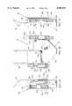
- FIG. 7Ais a side elevation view of the visual-display system of FIG. 1 with a mount which connects it to the helmet of FIG. 1; for clarity of illustration, the mount is not shown in FIG. 1 and an aerodynamic shroud of FIG. 1 is not shown in FIG. 7A;
- FIG. 7Bis a front elevation view of the visual-display system and mount of FIG. 7A;
- FIG. 7Cis an opposite side elevation view of the visual-display system and mount of FIG. 7A;
- FIG. 8is a front elevation view of an adjustable carrier in the mount of FIGS. 7A-7C;
- FIG. 9Ais an enlarged, schematized view along the plane 9--9 of FIG. 8 with the carrier in a first position;
- FIG. 9Bis a view similar to FIG. 9A with the carrier in a second position
- FIG. 10is an exemplary virtual image that is displayed by the visual-display system of FIG. 1;
- FIG. 11is a block diagram of an image generator control system which can be used when an image generator in the assembly of FIG. 1 is realized as a reconfigurable generator.
- FIG. 1An assembly 20 of a visual-display system 22 and a helmet 24 is shown in FIG. 1.
- FIG. 1illustrates the optical arrangement of the visual-display system 22 and the positioning of the visual-display system relative to the helmet 24.
- FIGS. 2-6illustrate details of an optical path of the visual-display system 22.
- FIGS. 7A, 7B and 7Cillustrate mechanical details of the visual-display system 22 and of a mount 26 which connects it with the helmet 24.
- FIGS. 8, 9A and 9Billustrate further details of the mount.
- the helmet 24 of FIG. 1has a shell 30 and a visor 32 which can rotate on the shell 30 between a down position and an up position.
- the visor 32is shown in its down position in FIG. 1.
- the shell 30includes a chin portion 34 which is fixed to the other portions of the shell.
- the helmet 24is configured with an interior 36 for reception of the head of a user of the visual-display system 20 and an exterior 37 which provides protection for the user's head.
- An aperture 38is formed in the visor 32 to facilitate the view of the user through the helmet 24.
- the visual-display system 22 of FIG. 1includes an image illuminator 40, an image generator 42, a reflective mirror 44, a convergent lens 46 and a combiner 48.
- the image illuminator 40is arranged to direct incident light (indicated by a broken line 50) upon a first face of the image generator 42 which produces transmitted light (indicated by a broken line 52) that radiates from a second face of the image generator 42.
- the transmitted light 52is reflected from the mirror 44 and directed to the lens 46.
- At least a portion (indicated by a broken line 54) of the transmitted light 52is reflected from the combiner 48 and directed through the visor 32 to one eye of the user of the visual-display system 22 (in the embodiment of FIG. 1, the combiner is positioned to present a virtual image to the right eye).
- FIG. 1shows that, except for the combiner 48, the elements of the visual-display system 22 are positioned within a housing 56 (indicated in broken lines) and are protected by an aerodynamic shroud 58 (partially indicated at the left side of the system 22). Only the combiner 48 extends above the housing 56 to be visible to the user.
- a more detailed description of the assembly 20will be facilitated by preceding it with a description of the optical path of the visual-display system 22 and a description of a mount which connects the system 22 with the helmet 24 (for clarity of illustration, the mount is not shown in FIG. 1).
- the lens 46is positioned between the image generator 42 and the eye 62 of the user of the visual-display system (22 in FIG. 1).
- the lens 46is a convergent lens, e.g., a convex lens or a plano-convex lens, with a focal length.
- the image generator 42is preferably positioned at a distance from the lens 46 that is equal to or less than the focal length.
- transmitted light 52 from a face 53 of the image generator 42is directed at the lens 46 and at least a portion 54 of this light is brought to a focus on the retina of the eye 62 by action of the lens 46 and the lens of the eye 62.
- the eye 62appears to see a virtual image 64 which is at the end of extensions 66 of rays of the transmitted light portions 54. If the image generator 42 and the lens 46 are separated by the focal length of the lens 46, the extension rays 66 will be collimated, i.e., parallel, and the perception areas in the brain of the user will perceive the virtual image 64 to be at infinity. If the image generator 42 and the lens 46 are separated by less than the focal length of the lens 46, the virtual image 64 will be perceived to be at a distance less than infinity.
- the simple optical path arrangement 60is generally known as a magnifier because the virtual image 64 is not only perceived to be at a distance greater than the distance to the lens 46 but it is magnified relative to the size of the image generator 42 (the virtual image 64 is aptly named because a screen placed at that location will not display an image). Typically, the distance to the virtual image 64 far exceeds the focal length of the lens 46. This spatial relationship is indicated in FIG. 2 by the introduction of a break 65 in the extension rays 66.
- FIG. 2Although the magnifier arrangement of FIG. 2 produces a magnified virtual image 64, it also obscures the view of the eye 62 because of the position of the lens 46 and the image generator 42. Accordingly, a combiner 48 is positioned as shown in FIG. 2 to obtain the optical path 70 of FIG. 3 in which the lens 46 and image generator 42 are swung downwards away from the field of view of the eye 62.
- the combiner 48is a partially reflective and partially transmissive mirror. Such mirrors are often referred to as beamsplitters.
- An exemplary beamsplitterconsists of a plate of optical glass having a deposited dielectric film on a first surface which produces partial reflection and an antireflection film deposited on a second surface. Beamsplitters are fabricated with various reflection/transmittance ratios, e.g., 30/70 and 50/50. Because of its ability to reflect and transmit, the combiner 48 "combines" the transmitted light portion 54 with light 68 from a distant visual scene (which is associated with the user's immediate task) and directs them to the eye 62. In practice, the reflection/transmittance ratio of the combiner 48 is selected to obtain a desired balance of the intensities of the light portion 54 and the scene light 68 for the eye 62.
- a reflective mirror 44is introduced into the optical path 70 to convert it to the optical path 76 of FIG. 4.
- the mirror 44is oriented at an angle which places the image generator 42 in an orthogonal relationship with its position in the optical path 70 of FIG. 3.
- an image illuminator 40is introduced in the optical path 80 of FIG. 5.
- the image illuminatoris directed at a face 81 of the image generator 42 which is opposite the face 53.
- the image illuminator 40includes a lamp 82 which has a radiant element 83. It also includes a heat shield 84, and a diffuser 86.
- the radiant element 83radiates illumination light 88 of which a portion is heat in the form of infrared light.
- the heat shield 84is preferably configured to reflect at least a portion of the infrared light from the optical path so that it does not overly heat the image generator 42.
- a reflective heat shieldremoves the thermal energy from the visual-image system (20 in FIG. 1) which simplifies the thermal design of the system.
- the diffuser 86diffuses the illumination light 88 to enhance the uniformity of the illumination of the face 81.
- a second reflective mirror 90is introduced between the lamp 82 and the image generator 42.
- the illumination light 88is directed by the mirror 90 to be incident upon the image generator face 81. If the illumination light 88 and the transmitted light 52 are considered to be first and second portions of the optical path 80, FIG. 5 illustrates that the compactness of the visual-display system 20 is enhanced by arranging the second mirror 90 so that the optical path portions 88 and 52 are substantially parallel.
- a transmissive liquid-crystal displayis especially suitable for use when the system 22 is in the presence of strong ambient light. With such a display, the intensity of the illumination system 40 can be increased as required to obtain a desired balance of the transmitted light portion 54 and the scene light 68 at the eye 62.
- the spatial shape of the radiant element 83is preferably configured to conform with the spatial shape of the image generator.
- FIG. 6illustrates a radiant element 83 in the form of a lamp filament.
- the radiant element 83is configured to substantially fill a rectangle 93 which is a reduced version of the shape of the face 81 of the image generator 42.
- the intensity and uniformity of the transmitted light portion 54can be further enhanced by including a lens in the lamp 82 which focuses the radiation of the radiant element 83 upon the face 81.
- FIGS. 7A-7Cillustrate a mount 26 that connects the visual-display system 22 and helmet 24 of FIG. 1.
- These figuresindicate the center of mass 100 of the visual-display system 22 and show the housing 56 which encloses the optical elements of the visual-display system except for the combiner 48.
- the combiner 48extends upward from the housing 56 so as to place it in a selected portion of the field of view of one eye of a user of the system (the housing is configured to provide an optical path between the lens 46 and the combiner 48).
- the mount 26includes a carrier 102 and a bracket 104 which is attached to one side of the housing 56.
- the carrier 102also includes a pair of hollow pins 106 that are fixed to the bracket 104 with screws 108.
- the carrier 102is formed to define a pair of lugs 110 which each have a slip-fit hole that slidingly receives a different one of the pins 106.
- Resilient members in the form of a pair of helical springs 112are captured between the screws 108 and the lugs 110.
- the mount 26further includes a bracket 114 which is attached to an opposite side of the housing 56 and the mount 102 carries a block 116. Another pair of guide pins 106 are attached to the block 116 with screws 108. The bracket 114 has slip-fit holes which each slidingly receive a different one of the pins 106. Another pair of springs 112 are captured between the screws 108 and the block 116.
- the mount 26also includes an energy-absorbing device in the form of a dashpot 120.
- the dashpot 120has a cylinder 122 which slidingly receives a piston 124.
- the cylinder 122is fixed to the housing 56 with a bracket 126 and the piston 124 is fixed to one of the guide pins 106 with another bracket 128.
- the optical display and helmet assembly 20 of FIG. 1When the optical display and helmet assembly 20 of FIG. 1 is used in an environment of strong shock and vibration forces, e.g., that of a racing vehicle, various frequencies of these forces are applied to the visual-display system 22 via the helmet 24. Because of the structure of the mount 26 in FIGS. 7A-7C, the visual-display system 22 can move vertically against the yielding compression of the springs 112 and the restoring force of the compressed springs 112 returns the system 22 back to an equilibrium position. The yielding suspension absorbs energy and reduces the movement frequency of the visual-display system 22 which enhances the quality of the virtual image as seen by the system user. This image view is further enhanced by the energy-absorbing device 120 which acts to dampen the vibration and shock frequencies.
- FIGS. 8, 9A and 9Billustrate that the mount 26 is secured to the helmet (24 in FIG. 1) by N attachment devices 130 (in order to illustrate the operation of the attachment devices 130, they are illustrated in enlarged, scheniatized views in FIGS. 9A and 9B).
- N3 which facilitates positioning the combiner (48 in FIGS. 7A-7C) by adjustment of attachment devices 130A, 130B and 130C.
- the mount 26includes screws 132 which have heads 134 with a arcuately-shaped portion 135.
- the carrier 102includes blocks 136 which have sockets 138.
- the blocks 136are preferably of a resilient material, e.g., nylon.
- a frontal portion 140 of the helmet shell's chin portion (34 in FIG. 1)is fitted with threaded nuts 142.
- the heads 134are rotatably received in the sockets 138 and the screws 132 threadably received in the nuts 142.
- rotating the screw of device 130Bchanges the vertical inclination of the carrier 102 as illustrated in FIG. 9B
- rotating the screws of the device 130Achanges the transverse inclination of the carrier 102
- Rotating the screw of the device 130Cchanges both inclinations and rotating all three screws together changes the spacing between the carrier 102 and the frontal portion 140.
- This attachment systemfacilitates adjustment of the position of the combiner (48 in FIG. 1) to accommodate each user of the visual display and helmet assembly (20 in FIG. 1).
- Access to the devices 130A-130Cis provided by through holes in the housing 56 such as the hole 144 indicated in FIG. 7B in broken lines. The through holes are positioned to avoid optical elements of the visual-display system 22.
- the helmet 24 and its exterior 37are configured to provide protection for the head of a user of the assembly 20. This protection is lessened if foreign objects are placed within the helmet's interior 36. Accordingly, the visual-display system 22 is positioned adjacent the helmet's exterior 37. To reduce the probability of injury, it is also important that the assembly 20 not induce twisting forces upon the user's head.
- the protective helmet 24 and the shroud 58(which surrounds the visual-display system 22) are symmetrically and aerodynamically configured about a vertical, fore-and-aft plane 150 which is substantially coplanar with the midsagittal plane (the vertical, fore-and-aft plane of the human body) of the user's head.
- the mount (26 in FIGS. 7A-7C)is arranged to place the center of mass (100 in FIGS. 7A-7C) of the visual-display system 22 substantially on the fore-and-aft plane 150.
- the mount(26 in FIGS. 7A-7C) is also configured to permit the visual-display system 22 to separate from the helmet 24 when the system 22 is subjected to forces over a predetermined threshold.
- the human eyeBecause the human eye has a pupil diameter of ⁇ 3 millimeters (in bright sunlight), it does not have to accommodate (tense or relax) to keep images focused on the retina if those images are all distant by greater than ⁇ 3.7 meters. In addition, at a distance of ⁇ 4 meters, the light rays of a monocular virtual image are substantially parallel with those of a distant scene and the perception of double images is avoided. Laboratory studies indicate that size and distance estimation of objects are affected by the convergence-controlling muscles of the eye. The near point (closest point of accommodation) of the human eye is in the range of 100-200 millimeters. The eye will be attracted to objects which are beyond the near point and will try to focus on them.
- the path spacing between the image generator 42 and the lens 46is arranged so that the virtual image 64 is greater than ⁇ 4 meters from the user's eye 62 (see FIG. 5).
- the combiner 48is typically enclosed in a thin frame and, accordingly, the combiner 48 is spaced less than ⁇ 88 millimeters from the user's eye to reduce its attraction to the eye.
- the combiner 48is selected with a transparency which is sufficient to reduce binocular rivalry, i.e., the lighting of the distant scene is sufficiently balanced. Confusion in the perception areas of the brain are preferably reduced by positioning the combiner 42 so that the virtual image 64 is visible to only one eye (e.g., positioned downward and to one side of the fore-and-aft plane 100).
- the field of view of the virtual image 64 in FIG. 5is selected to minimize its effect upon the distant scene while still permitting the display of the desired information, e.g., the information of the image 160 in FIG. 10.
- An exemplary field of viewis 5° vertically and 10° horizontally and an exemplary combiner size is 6.2 ⁇ 12.7 millimeters.
- a high degree of angular resolutione.g., ⁇ 3 pixels/milli-radian, is obtained in the virtual image.
- transmissive liquid-crystal displaysare smaller than conventional displays, e.g., cathode-ray tubes, the focal length of the lens 46 can be reduced and the spacing between the illumination system 40 and the image generator 42 can also be reduced.
- a working prototype of the assembly 20 of FIG. 1was fabricated and tested.
- the prototype helmet 24was part number Feuling SS by Bell Sports of Rantoul, Ill.
- the image generator 42was a F07KM200 transmissive liquid-crystal display from Epson America, Inc.
- the convergent lens 46had a focal length of 75 millimeters
- the combiner 48was a plate beamsplitter part number 03BTF007 (of polycarbonate resin with a reflection/transmittance ratio of 50/50) from Helles Griot of Irvine, Calif.
- the lamp 82was a lens-end, halogen lamp, part number L8017 from Gilway Technical Lamp of Woburn, Mass.
- the heat shield 84was a wide band hot mirror from OCLI of Santa Rosa, Calif.
- transluscent tapewas used for the diffuser 86 but an exemplary glass diffuser would be part number M43,724 from Edmund Scientific of Barrington, N.J.
- the spacing between the lens 46 and the image generator 42was set somewhat less than the focal length of the lens 46 to place the virtual image (64 in FIG. 5) ⁇ 3.5 meters from the user's eye (62 in FIG. 5).
- the lens 46was spaced ⁇ 45 millimeters from the combiner 48 to position the lens 46 and other system elements out of the field of view of the system user.
- the lamp 82had an optical path spacing of ⁇ 30 millimeters from the image generator 42.
- the selected liquid-crystal display 42can display 256 colors, it has screen dimensions of ⁇ 14 millimeters ⁇ ⁇ 10 millimeters and a pixel count of 640 ⁇ 260.
- Electronic data, lamp power and other signal and voltage formswere provided to the visual-display system 22 through an umbilical cord which was connected through a quick-release connector. Because the prototype was especially configured for use in a high-speed, racing vehicle, it was programmed to display the information indicia in the virtual image 160 shown in FIG. 10.
- the color bar 162was filled with a color up to the present speed, e.g., the line 172. Above a predetermined safe level, e.g., 12,000 revolutions per minute, the filled color changed to a warning color, e.g., red.
- a predetermined safe levele.g. 12,000 revolutions per minute
- the engine status signalsare received from an engine control module and the external signals, e.g., the track condition signals, are received through a telemetry system.
- FIG. 10illustrates the communication advantages that are gained when the display generator 42 is realized with a color display.
- the weight of the visual-display system 22 prototypewas ⁇ 100 grams. It was ⁇ 20 millimeters thick with transverse measurements of ⁇ 60 millimeters ⁇ ⁇ 90 millimeters.
- the mount 26was configured to allow up to 2.5 millimeters of vertical movement of the visual-display system 22.
- the prototype of the visual-display system 22 and the helmet 24were fitted with accelerometers and a time history was compiled under severe vibration conditions. This testing resulted in the selection of a spring constant of 8 for the springs 112 of the mount 26 (see FIGS. 7A-7C). With a pre-load compression of ⁇ 3 millimeters, each spring exerted a restoring force of ⁇ 0.45 kilograms upon the system 22.
- the image generator 42 of FIGS. 1-5can be realized with a segmented liquid crystal display.
- a segmented displayis one which has discrete areas dedicated for the display of predetermined indicia, e.g., message, picture or icon. This indicia can be displayed upon command but its format cannot be changed. For example, a set of several segments can be positioned such that the numbers 0, 1, 2 and so on can be displayed by segments of the set. This set cannot be changed to display a different indicia, e.g., an icon. That is, this set of icons cannot be "reconfigured".
- each pixel of an array of pixelsis independently controlled by an input signal so that the display can be commanded to show any indicia that can be formed by that array.
- the virtual image of 160can be reprogrammed to change the selected information indicia. For example, during practice runs of a racing vehicle the prototype display of FIG. 10 could be programmed, i.e., reconfigured, to display additional indicia, e.g., lap speed.
- FIG. 11illustrates a block diagram 180 of an exemplary, image generator control system in which the image generator 42 of FIG. 1 is realized as a reconfigurable liquid-crystal display 182.
- the systemalso includes a data processor 184 which receives input signals from an engine control module 186 and a telemetry receiver 187. In response to these input signals and to a stored program, the processor 184 generates control signals in a signal format, e.g., video graphics array signals (VGA), which is structured for driving pixel arrays.
- VGAvideo graphics array signals
- These control signalsare converted in a video encoder 188 to signals, e.g., National Television System Committee (NTSC) signals, which are accepted by the liquid-crystal display 182.
- NTSCNational Television System Committee
Landscapes
- Physics & Mathematics (AREA)
- Engineering & Computer Science (AREA)
- General Physics & Mathematics (AREA)
- Optics & Photonics (AREA)
- Theoretical Computer Science (AREA)
- Aviation & Aerospace Engineering (AREA)
- Business, Economics & Management (AREA)
- Educational Administration (AREA)
- Educational Technology (AREA)
Abstract
Description
Claims (29)
Priority Applications (1)
| Application Number | Priority Date | Filing Date | Title |
|---|---|---|---|
| US08/594,159US5856811A (en) | 1996-01-31 | 1996-01-31 | Visual display and helmet assembly |
Applications Claiming Priority (1)
| Application Number | Priority Date | Filing Date | Title |
|---|---|---|---|
| US08/594,159US5856811A (en) | 1996-01-31 | 1996-01-31 | Visual display and helmet assembly |
Publications (1)
| Publication Number | Publication Date |
|---|---|
| US5856811Atrue US5856811A (en) | 1999-01-05 |
Family
ID=24377780
Family Applications (1)
| Application Number | Title | Priority Date | Filing Date |
|---|---|---|---|
| US08/594,159Expired - LifetimeUS5856811A (en) | 1996-01-31 | 1996-01-31 | Visual display and helmet assembly |
Country Status (1)
| Country | Link |
|---|---|
| US (1) | US5856811A (en) |
Cited By (52)
| Publication number | Priority date | Publication date | Assignee | Title |
|---|---|---|---|---|
| US6016160A (en)* | 1993-03-31 | 2000-01-18 | Cairns & Brother Inc. | Combination head-protective helmet and thermal imaging apparatus |
| US6028627A (en)* | 1997-06-04 | 2000-02-22 | Helmsderfer; John A. | Camera system for capturing a sporting activity from the perspective of the participant |
| US6160666A (en) | 1994-02-07 | 2000-12-12 | I-O Display Systems Llc | Personal visual display system |
| US6255650B1 (en) | 1998-12-11 | 2001-07-03 | Flir Systems, Inc. | Extreme temperature radiometry and imaging apparatus |
| US20020008675A1 (en)* | 2000-06-14 | 2002-01-24 | Theodore Mayer | Method and apparatus for seamless integration of images using a transmissive/reflective mirror |
| US20030142041A1 (en)* | 2002-01-30 | 2003-07-31 | Delphi Technologies, Inc. | Eye tracking/HUD system |
| US20030156742A1 (en)* | 2002-02-19 | 2003-08-21 | Witt Gerald J. | Auto calibration and personalization of eye tracking system using larger field of view imager with higher resolution |
| US20030188169A1 (en)* | 2002-03-27 | 2003-10-02 | Strongin Geoffrey S. | System and method for controlling device-to-device accesses within a computer system |
| EP1162088A3 (en)* | 2000-06-09 | 2003-10-15 | Honda Giken Kogyo Kabushiki Kaisha | Apparatus for detecting tire air pressure for motor vehicle |
| US20030209960A1 (en)* | 2002-05-13 | 2003-11-13 | Delphi Technologies, Inc. | Heating element for fluorescent lamps |
| US20040113887A1 (en)* | 2002-08-27 | 2004-06-17 | University Of Southern California | partially real and partially simulated modular interactive environment |
| US6753879B1 (en)* | 2000-07-03 | 2004-06-22 | Intel Corporation | Creating overlapping real and virtual images |
| US20040125047A1 (en)* | 2002-08-23 | 2004-07-01 | Kopin Corporation | Headgear system with display |
| DE10307324B3 (en)* | 2003-02-17 | 2004-08-19 | Schuberth Werk Gmbh | Protective helmet for motor racing driver has integrated display device moved away from helmet wearer upon detection of impact for preventing injury |
| US20050068256A1 (en)* | 2003-09-26 | 2005-03-31 | Lite-On Automotive Corp. | Helmet with a tire status apparatus |
| US20050177929A1 (en)* | 2000-10-11 | 2005-08-18 | Greenwald Richard M. | Power management of a system for measuring the acceleration of a body part |
| US20060017654A1 (en)* | 2004-07-23 | 2006-01-26 | Romo Justin R | Virtual reality interactivity system and method |
| US20060232853A1 (en)* | 2005-04-14 | 2006-10-19 | Carl Zeiss Jena Gmbh | Projection unit for a head-up display |
| EP1787538A1 (en)* | 2005-11-18 | 2007-05-23 | Vectronix AG | Helmet fixing for an optical device, particularly for night-sights |
| US7767963B1 (en) | 2006-12-08 | 2010-08-03 | Draeger Safety, Inc. | Thermal imaging camera internal damping system |
| WO2014179604A1 (en)* | 2013-05-01 | 2014-11-06 | Jason Klein | Mask |
| WO2016037539A1 (en)* | 2014-09-09 | 2016-03-17 | 泰克曼(南京)电子有限公司 | Welding mask with head-up display auto-darkening filter |
| WO2016044036A1 (en)* | 2014-09-17 | 2016-03-24 | Microsoft Technology Licensing, Llc | Eliminating binocular rivalry in monocular displays |
| WO2016074017A1 (en)* | 2014-11-11 | 2016-05-19 | Tobin King | Improvements in protective headgear |
| US9500868B2 (en) | 2014-07-10 | 2016-11-22 | Honeywell International Inc. | Space suit helmet display system |
| US9622661B2 (en) | 2000-10-11 | 2017-04-18 | Riddell, Inc. | Impact monitoring system for players engaged in a sporting activity |
| US9848127B2 (en) | 2015-07-14 | 2017-12-19 | Honeywell International Inc. | System and method for a compact display |
| US9913507B2 (en) | 2012-11-10 | 2018-03-13 | Intel Corporation | Retractable displays for helmets |
| US20180275754A1 (en)* | 2017-03-23 | 2018-09-27 | Thomson Licensing | Device and method for immersive visual representations and individual head equipment |
| US10292650B2 (en) | 2000-10-11 | 2019-05-21 | Riddell, Inc. | System for monitoring a physiological parameter of players engaged in a sporting activity |
| WO2020130028A1 (en)* | 2018-12-20 | 2020-06-25 | Nsウエスト株式会社 | Head-up display device and helmet |
| JP2020100911A (en)* | 2018-12-20 | 2020-07-02 | Nsウエスト株式会社 | Helmet |
| US10945601B2 (en) | 2000-10-11 | 2021-03-16 | Riddell, Inc. | System and method for evaluating and providing treatment to sports participants |
| US10952671B2 (en) | 2000-10-11 | 2021-03-23 | Riddell, Inc. | System for monitoring a physiological parameter of players engaged in a sporting activity |
| USD927084S1 (en) | 2018-11-22 | 2021-08-03 | Riddell, Inc. | Pad member of an internal padding assembly of a protective sports helmet |
| CN113242699A (en)* | 2018-12-20 | 2021-08-10 | Ns西日本株式会社 | Head-up display device and helmet |
| US11185255B2 (en) | 2011-09-01 | 2021-11-30 | Riddell, Inc. | Systems and methods for monitoring a physiological parameter of persons engaged in physical activity |
| US20220038675A1 (en)* | 2020-01-22 | 2022-02-03 | Photonic Medical Inc. | Open view, multi-modal, calibrated digital loupe with depth sensing |
| US11399589B2 (en) | 2018-08-16 | 2022-08-02 | Riddell, Inc. | System and method for designing and manufacturing a protective helmet tailored to a selected group of helmet wearers |
| US20220256119A1 (en)* | 2021-02-05 | 2022-08-11 | Coretronic Corporation | Medical image assistance system and medical image assistance method |
| US11419383B2 (en) | 2013-01-18 | 2022-08-23 | Riddell, Inc. | System and method for custom forming a protective helmet for a customer's head |
| US20230046644A1 (en)* | 2020-01-20 | 2023-02-16 | Leica Instruments (Singapore) Pte. Ltd. | Apparatuses, Methods and Computer Programs for Controlling a Microscope System |
| US11937895B1 (en)* | 2009-06-04 | 2024-03-26 | Optics Innovation Llc | Method and apparatus for a compact and high resolution mind-view communicator |
| US20240163429A1 (en)* | 2022-11-16 | 2024-05-16 | International Business Machines Corporation | Visual data transmission by an air-gapped system |
| US11992076B2 (en) | 2013-05-01 | 2024-05-28 | F3 Tech, Llc | Mask |
| EP4360489A3 (en)* | 2018-12-20 | 2024-07-03 | NS West Inc. | Helmet with a head up display |
| US20240340511A1 (en)* | 2021-04-27 | 2024-10-10 | Apple Inc. | Camera integration for portable electronic devices |
| US12117619B1 (en)* | 2021-08-23 | 2024-10-15 | Meta Platforms Technologies, Llc | Head mounted device and camera module |
| US12125285B1 (en) | 2009-06-04 | 2024-10-22 | Optics Innovation Llc | Method and apparatus for a wearable computer |
| US12229922B1 (en) | 2018-07-11 | 2025-02-18 | Optics Innovation Llc | Method and apparatus for a software enabled high resolution ultrasound imaging device |
| US12303766B2 (en) | 2018-11-21 | 2025-05-20 | Riddell, Inc. | Protective sports helmet with additively manufactured components |
| USRE50624E1 (en) | 2018-11-19 | 2025-10-07 | Optics Innovation Llc | Method and apparatus for super resolution imaging and eye tracking devices |
Citations (33)
| Publication number | Priority date | Publication date | Assignee | Title |
|---|---|---|---|---|
| US3059519A (en)* | 1956-09-05 | 1962-10-23 | Austin N Stanton | Headgear mounted cathode ray tube and binocular viewing device |
| US3170979A (en)* | 1962-04-30 | 1965-02-23 | Alan W Baldwin | Optical image interposing display device |
| US3205303A (en)* | 1961-03-27 | 1965-09-07 | Philco Corp | Remotely controlled remote viewing system |
| US3608935A (en)* | 1970-01-28 | 1971-09-28 | Hughes Aircraft Co | Helmet mounted display unit with fastener device |
| US3666887A (en)* | 1968-06-29 | 1972-05-30 | Pilkington Perkin Elmer Ltd | Head-up displays |
| US3712714A (en)* | 1971-06-15 | 1973-01-23 | L Uyeda | Information display for diver{40 s face mask |
| US3833300A (en)* | 1973-05-14 | 1974-09-03 | Us Navy | Three {37 d{38 {11 weapons sight |
| US3870405A (en)* | 1973-06-12 | 1975-03-11 | Honeywell Inc | Helmet sight visors |
| US3923370A (en)* | 1974-10-15 | 1975-12-02 | Honeywell Inc | Head mounted displays |
| USRE28847E (en)* | 1972-06-28 | 1976-06-08 | Honeywell Inc. | Inside helmet sight display apparatus |
| US4026641A (en)* | 1975-12-30 | 1977-05-31 | The United States Of America As Represented By The Secretary Of The Army | Toric reflector display |
| US4153913A (en)* | 1976-06-18 | 1979-05-08 | Pilkington P.E. Limited | Head-up displays |
| US4156292A (en)* | 1978-05-23 | 1979-05-29 | The United States Of America As Represented By The Secretary Of The Army | Display carrying and protective helmet |
| US4181405A (en)* | 1978-08-07 | 1980-01-01 | The Singer Company | Head-up viewing display |
| US4220400A (en)* | 1977-02-22 | 1980-09-02 | Honeywell Inc. | Display apparatus with reflective separated structure |
| US4231117A (en)* | 1979-01-15 | 1980-11-04 | Gentex Corporation | Helmet assembly for accurately positioning visual display system |
| US4361384A (en)* | 1980-06-27 | 1982-11-30 | The United States Of America As Represented By The Secretary Of The Army | High luminance miniature display |
| US4439157A (en)* | 1982-05-03 | 1984-03-27 | The United States Of America As Represented By The Secretary Of The Navy | Helmet mounted display projector |
| US4465347A (en)* | 1982-11-15 | 1984-08-14 | The United States Of America As Represented By The Secretary Of The Air Force | Helmet mounted telescope |
| US4719462A (en)* | 1986-11-17 | 1988-01-12 | Hawkins David E | Radar detection helmet |
| US4722601A (en)* | 1983-07-23 | 1988-02-02 | Ferranti Plc | Apparatus for determining the direction of a line of sight |
| US4751691A (en)* | 1987-07-01 | 1988-06-14 | Perera Kalukapuge T | Optical projection time-piece attachment for spectacles or combination thereof |
| US4753514A (en)* | 1986-05-12 | 1988-06-28 | Iota Instrumentation Co. | Headwear-mounted periscopic display device |
| US4757714A (en)* | 1986-09-25 | 1988-07-19 | Insight, Inc. | Speed sensor and head-mounted data display |
| US4761056A (en)* | 1987-03-27 | 1988-08-02 | Kaiser Aerospace And Electronics Corporation | Compact helmet mounted display |
| US4806011A (en)* | 1987-07-06 | 1989-02-21 | Bettinger David S | Spectacle-mounted ocular display apparatus |
| US4869575A (en)* | 1986-05-12 | 1989-09-26 | Iota Instrumentation Company | Headwear-mounted periscopic display device |
| US4977401A (en)* | 1988-09-07 | 1990-12-11 | Saab-Scania Aktiebolag | Head-up display |
| US5189512A (en)* | 1991-07-01 | 1993-02-23 | Camair Research, Inc. | Helmet integrated display system |
| GB2238627B (en)* | 1989-11-29 | 1994-04-06 | Yazaki Corp | Display apparatus |
| US5321416A (en)* | 1992-07-27 | 1994-06-14 | Virtual Research Systems | Head-mounted visual display apparatus |
| US5581271A (en)* | 1994-12-05 | 1996-12-03 | Hughes Aircraft Company | Head mounted visual display |
| US5585813A (en)* | 1992-10-05 | 1996-12-17 | Rockwell International Corporation | All aspect head aiming display |
- 1996
- 1996-01-31USUS08/594,159patent/US5856811A/ennot_activeExpired - Lifetime
Patent Citations (34)
| Publication number | Priority date | Publication date | Assignee | Title |
|---|---|---|---|---|
| US3059519A (en)* | 1956-09-05 | 1962-10-23 | Austin N Stanton | Headgear mounted cathode ray tube and binocular viewing device |
| US3205303A (en)* | 1961-03-27 | 1965-09-07 | Philco Corp | Remotely controlled remote viewing system |
| US3170979A (en)* | 1962-04-30 | 1965-02-23 | Alan W Baldwin | Optical image interposing display device |
| US3666887A (en)* | 1968-06-29 | 1972-05-30 | Pilkington Perkin Elmer Ltd | Head-up displays |
| US3608935A (en)* | 1970-01-28 | 1971-09-28 | Hughes Aircraft Co | Helmet mounted display unit with fastener device |
| US3712714A (en)* | 1971-06-15 | 1973-01-23 | L Uyeda | Information display for diver{40 s face mask |
| USRE28847E (en)* | 1972-06-28 | 1976-06-08 | Honeywell Inc. | Inside helmet sight display apparatus |
| US3833300A (en)* | 1973-05-14 | 1974-09-03 | Us Navy | Three {37 d{38 {11 weapons sight |
| US3870405A (en)* | 1973-06-12 | 1975-03-11 | Honeywell Inc | Helmet sight visors |
| US3923370A (en)* | 1974-10-15 | 1975-12-02 | Honeywell Inc | Head mounted displays |
| US4026641A (en)* | 1975-12-30 | 1977-05-31 | The United States Of America As Represented By The Secretary Of The Army | Toric reflector display |
| US4153913A (en)* | 1976-06-18 | 1979-05-08 | Pilkington P.E. Limited | Head-up displays |
| US4220400A (en)* | 1977-02-22 | 1980-09-02 | Honeywell Inc. | Display apparatus with reflective separated structure |
| US4156292A (en)* | 1978-05-23 | 1979-05-29 | The United States Of America As Represented By The Secretary Of The Army | Display carrying and protective helmet |
| US4181405A (en)* | 1978-08-07 | 1980-01-01 | The Singer Company | Head-up viewing display |
| US4231117A (en)* | 1979-01-15 | 1980-11-04 | Gentex Corporation | Helmet assembly for accurately positioning visual display system |
| US4361384A (en)* | 1980-06-27 | 1982-11-30 | The United States Of America As Represented By The Secretary Of The Army | High luminance miniature display |
| US4439157A (en)* | 1982-05-03 | 1984-03-27 | The United States Of America As Represented By The Secretary Of The Navy | Helmet mounted display projector |
| US4465347A (en)* | 1982-11-15 | 1984-08-14 | The United States Of America As Represented By The Secretary Of The Air Force | Helmet mounted telescope |
| US4722601A (en)* | 1983-07-23 | 1988-02-02 | Ferranti Plc | Apparatus for determining the direction of a line of sight |
| US4753514A (en)* | 1986-05-12 | 1988-06-28 | Iota Instrumentation Co. | Headwear-mounted periscopic display device |
| US4869575A (en)* | 1986-05-12 | 1989-09-26 | Iota Instrumentation Company | Headwear-mounted periscopic display device |
| US5162828A (en)* | 1986-09-25 | 1992-11-10 | Furness Thomas A | Display system for a head mounted viewing transparency |
| US4757714A (en)* | 1986-09-25 | 1988-07-19 | Insight, Inc. | Speed sensor and head-mounted data display |
| US4719462A (en)* | 1986-11-17 | 1988-01-12 | Hawkins David E | Radar detection helmet |
| US4761056A (en)* | 1987-03-27 | 1988-08-02 | Kaiser Aerospace And Electronics Corporation | Compact helmet mounted display |
| US4751691A (en)* | 1987-07-01 | 1988-06-14 | Perera Kalukapuge T | Optical projection time-piece attachment for spectacles or combination thereof |
| US4806011A (en)* | 1987-07-06 | 1989-02-21 | Bettinger David S | Spectacle-mounted ocular display apparatus |
| US4977401A (en)* | 1988-09-07 | 1990-12-11 | Saab-Scania Aktiebolag | Head-up display |
| GB2238627B (en)* | 1989-11-29 | 1994-04-06 | Yazaki Corp | Display apparatus |
| US5189512A (en)* | 1991-07-01 | 1993-02-23 | Camair Research, Inc. | Helmet integrated display system |
| US5321416A (en)* | 1992-07-27 | 1994-06-14 | Virtual Research Systems | Head-mounted visual display apparatus |
| US5585813A (en)* | 1992-10-05 | 1996-12-17 | Rockwell International Corporation | All aspect head aiming display |
| US5581271A (en)* | 1994-12-05 | 1996-12-03 | Hughes Aircraft Company | Head mounted visual display |
Cited By (88)
| Publication number | Priority date | Publication date | Assignee | Title |
|---|---|---|---|---|
| US6016160A (en)* | 1993-03-31 | 2000-01-18 | Cairns & Brother Inc. | Combination head-protective helmet and thermal imaging apparatus |
| US6160666A (en) | 1994-02-07 | 2000-12-12 | I-O Display Systems Llc | Personal visual display system |
| US6028627A (en)* | 1997-06-04 | 2000-02-22 | Helmsderfer; John A. | Camera system for capturing a sporting activity from the perspective of the participant |
| US20060081778A1 (en)* | 1998-12-11 | 2006-04-20 | Warner Charles C | Portable radiometry and imaging apparatus |
| US6255650B1 (en) | 1998-12-11 | 2001-07-03 | Flir Systems, Inc. | Extreme temperature radiometry and imaging apparatus |
| US7411193B2 (en) | 1998-12-11 | 2008-08-12 | Flir Systems, Inc. | Portable radiometry and imaging apparatus |
| US6849849B1 (en) | 1998-12-11 | 2005-02-01 | Flir Systems, Inc. | Portable radiometry and imaging apparatus |
| US20090121135A1 (en)* | 1998-12-11 | 2009-05-14 | Flir Systems, Inc. | Portable radiometry and imaging apparatus |
| EP1162088A3 (en)* | 2000-06-09 | 2003-10-15 | Honda Giken Kogyo Kabushiki Kaisha | Apparatus for detecting tire air pressure for motor vehicle |
| US20020008675A1 (en)* | 2000-06-14 | 2002-01-24 | Theodore Mayer | Method and apparatus for seamless integration of images using a transmissive/reflective mirror |
| US7227510B2 (en) | 2000-06-14 | 2007-06-05 | Panoram Technologies, Inc. | Method and apparatus for seamless integration of images using a transmissive/reflective mirror |
| US6753879B1 (en)* | 2000-07-03 | 2004-06-22 | Intel Corporation | Creating overlapping real and virtual images |
| US10945601B2 (en) | 2000-10-11 | 2021-03-16 | Riddell, Inc. | System and method for evaluating and providing treatment to sports participants |
| US10952671B2 (en) | 2000-10-11 | 2021-03-23 | Riddell, Inc. | System for monitoring a physiological parameter of players engaged in a sporting activity |
| US10702152B2 (en) | 2000-10-11 | 2020-07-07 | Riddell, Inc. | Impact monitoring system for players engaged in a sporting activity |
| US9622661B2 (en) | 2000-10-11 | 2017-04-18 | Riddell, Inc. | Impact monitoring system for players engaged in a sporting activity |
| US10292650B2 (en) | 2000-10-11 | 2019-05-21 | Riddell, Inc. | System for monitoring a physiological parameter of players engaged in a sporting activity |
| US20050177929A1 (en)* | 2000-10-11 | 2005-08-18 | Greenwald Richard M. | Power management of a system for measuring the acceleration of a body part |
| US7526389B2 (en)* | 2000-10-11 | 2009-04-28 | Riddell, Inc. | Power management of a system for measuring the acceleration of a body part |
| US6926429B2 (en) | 2002-01-30 | 2005-08-09 | Delphi Technologies, Inc. | Eye tracking/HUD system |
| US20030142041A1 (en)* | 2002-01-30 | 2003-07-31 | Delphi Technologies, Inc. | Eye tracking/HUD system |
| US6873714B2 (en) | 2002-02-19 | 2005-03-29 | Delphi Technologies, Inc. | Auto calibration and personalization of eye tracking system using larger field of view imager with higher resolution |
| US20030156742A1 (en)* | 2002-02-19 | 2003-08-21 | Witt Gerald J. | Auto calibration and personalization of eye tracking system using larger field of view imager with higher resolution |
| US20030188169A1 (en)* | 2002-03-27 | 2003-10-02 | Strongin Geoffrey S. | System and method for controlling device-to-device accesses within a computer system |
| US6833657B2 (en) | 2002-05-13 | 2004-12-21 | Delphi Technologies, Inc. | Heating element for fluorescent lamps |
| US20030209960A1 (en)* | 2002-05-13 | 2003-11-13 | Delphi Technologies, Inc. | Heating element for fluorescent lamps |
| US20040125047A1 (en)* | 2002-08-23 | 2004-07-01 | Kopin Corporation | Headgear system with display |
| US20040113887A1 (en)* | 2002-08-27 | 2004-06-17 | University Of Southern California | partially real and partially simulated modular interactive environment |
| DE10307324B3 (en)* | 2003-02-17 | 2004-08-19 | Schuberth Werk Gmbh | Protective helmet for motor racing driver has integrated display device moved away from helmet wearer upon detection of impact for preventing injury |
| US20050068256A1 (en)* | 2003-09-26 | 2005-03-31 | Lite-On Automotive Corp. | Helmet with a tire status apparatus |
| US20060017654A1 (en)* | 2004-07-23 | 2006-01-26 | Romo Justin R | Virtual reality interactivity system and method |
| US20060232853A1 (en)* | 2005-04-14 | 2006-10-19 | Carl Zeiss Jena Gmbh | Projection unit for a head-up display |
| EP1787538A1 (en)* | 2005-11-18 | 2007-05-23 | Vectronix AG | Helmet fixing for an optical device, particularly for night-sights |
| US7767963B1 (en) | 2006-12-08 | 2010-08-03 | Draeger Safety, Inc. | Thermal imaging camera internal damping system |
| US12336782B2 (en)* | 2009-06-04 | 2025-06-24 | Optics Innovation Llc | Method and apparatus for a compact and high resolution mind-view communicator |
| US20250134374A1 (en)* | 2009-06-04 | 2025-05-01 | Optics Innovation Llc | Method and apparatus for a compact and high resolution mind-view communicator |
| US20250134375A1 (en)* | 2009-06-04 | 2025-05-01 | Optics Innovation Llc | Method and apparatus for a compact and high resolution mind-view communicator |
| US12303228B2 (en)* | 2009-06-04 | 2025-05-20 | Optics Innovation Llc | Method and apparatus for a compact and high resolution mind-view communicator |
| US12125285B1 (en) | 2009-06-04 | 2024-10-22 | Optics Innovation Llc | Method and apparatus for a wearable computer |
| US20240172940A1 (en)* | 2009-06-04 | 2024-05-30 | Optics Innovation Llc | Method and apparatus for a compact and high resolution mind-view communicator |
| US12340590B2 (en) | 2009-06-04 | 2025-06-24 | Optics Innovation Llc | Method and apparatus for a wearable computer |
| US12376747B2 (en)* | 2009-06-04 | 2025-08-05 | Optics Innovation Llc | Method and apparatus for a compact and high resolution mind-view communicator |
| US11937895B1 (en)* | 2009-06-04 | 2024-03-26 | Optics Innovation Llc | Method and apparatus for a compact and high resolution mind-view communicator |
| US11185255B2 (en) | 2011-09-01 | 2021-11-30 | Riddell, Inc. | Systems and methods for monitoring a physiological parameter of persons engaged in physical activity |
| US12324471B2 (en)* | 2012-11-10 | 2025-06-10 | Tahoe Research, Ltd. | Retractable displays for helmets |
| US11771163B2 (en)* | 2012-11-10 | 2023-10-03 | Tahoe Research, Ltd. | Retractable displays for helmets |
| US20240023663A1 (en)* | 2012-11-10 | 2024-01-25 | Tahoe Research, Ltd. | Retractable displays for helmets |
| US10334903B2 (en) | 2012-11-10 | 2019-07-02 | Intel Corporation | Retractable displays for helmets |
| US9913507B2 (en) | 2012-11-10 | 2018-03-13 | Intel Corporation | Retractable displays for helmets |
| US11419383B2 (en) | 2013-01-18 | 2022-08-23 | Riddell, Inc. | System and method for custom forming a protective helmet for a customer's head |
| US11992076B2 (en) | 2013-05-01 | 2024-05-28 | F3 Tech, Llc | Mask |
| CN105705052A (en)* | 2013-05-01 | 2016-06-22 | F3技术有限责任公司 | protective mask |
| CN105705052B (en)* | 2013-05-01 | 2020-07-17 | F3技术有限责任公司 | Protective mask |
| US10912345B2 (en) | 2013-05-01 | 2021-02-09 | F3 Tech, Llc | Mask |
| WO2014179604A1 (en)* | 2013-05-01 | 2014-11-06 | Jason Klein | Mask |
| US9949523B2 (en) | 2013-05-01 | 2018-04-24 | F3 Tech, Llc. | Mask |
| US9500868B2 (en) | 2014-07-10 | 2016-11-22 | Honeywell International Inc. | Space suit helmet display system |
| WO2016037539A1 (en)* | 2014-09-09 | 2016-03-17 | 泰克曼(南京)电子有限公司 | Welding mask with head-up display auto-darkening filter |
| US10555836B2 (en) | 2014-09-09 | 2020-02-11 | Tecmen Electronics Co., Ltd. | Welding helmet having a HUD-type auto-darkening filter |
| WO2016044036A1 (en)* | 2014-09-17 | 2016-03-24 | Microsoft Technology Licensing, Llc | Eliminating binocular rivalry in monocular displays |
| WO2016074017A1 (en)* | 2014-11-11 | 2016-05-19 | Tobin King | Improvements in protective headgear |
| US9848127B2 (en) | 2015-07-14 | 2017-12-19 | Honeywell International Inc. | System and method for a compact display |
| US10534430B2 (en)* | 2017-03-23 | 2020-01-14 | Interdigital Ce Patent Holdings | Device and method for immersive visual representations and individual head equipment |
| US20180275754A1 (en)* | 2017-03-23 | 2018-09-27 | Thomson Licensing | Device and method for immersive visual representations and individual head equipment |
| US12229922B1 (en) | 2018-07-11 | 2025-02-18 | Optics Innovation Llc | Method and apparatus for a software enabled high resolution ultrasound imaging device |
| US11399589B2 (en) | 2018-08-16 | 2022-08-02 | Riddell, Inc. | System and method for designing and manufacturing a protective helmet tailored to a selected group of helmet wearers |
| US12268270B2 (en) | 2018-08-16 | 2025-04-08 | Riddell, Inc. | Position specific protective sports helmet |
| US12059051B2 (en) | 2018-08-16 | 2024-08-13 | Riddell, Inc. | System and method for designing and manufacturing a protective sports helmet |
| US12161183B2 (en) | 2018-08-16 | 2024-12-10 | Riddell, Inc. | System for monitoring a physiological parameter of a person wearing protective sports equipment while engaged in physical activity |
| USRE50624E1 (en) | 2018-11-19 | 2025-10-07 | Optics Innovation Llc | Method and apparatus for super resolution imaging and eye tracking devices |
| US12303766B2 (en) | 2018-11-21 | 2025-05-20 | Riddell, Inc. | Protective sports helmet with additively manufactured components |
| USD927084S1 (en) | 2018-11-22 | 2021-08-03 | Riddell, Inc. | Pad member of an internal padding assembly of a protective sports helmet |
| EP4360489A3 (en)* | 2018-12-20 | 2024-07-03 | NS West Inc. | Helmet with a head up display |
| WO2020130028A1 (en)* | 2018-12-20 | 2020-06-25 | Nsウエスト株式会社 | Head-up display device and helmet |
| CN113242699A (en)* | 2018-12-20 | 2021-08-10 | Ns西日本株式会社 | Head-up display device and helmet |
| EP3888482A4 (en)* | 2018-12-20 | 2022-03-02 | NS West Inc. | HEADUP INDICATOR AND HELMET |
| JP2020100911A (en)* | 2018-12-20 | 2020-07-02 | Nsウエスト株式会社 | Helmet |
| US20230046644A1 (en)* | 2020-01-20 | 2023-02-16 | Leica Instruments (Singapore) Pte. Ltd. | Apparatuses, Methods and Computer Programs for Controlling a Microscope System |
| US11611735B2 (en)* | 2020-01-22 | 2023-03-21 | Photonic Medical Inc. | Open view, multi-modal, calibrated digital loupe with depth sensing |
| US12075019B2 (en) | 2020-01-22 | 2024-08-27 | Photonic Medical Inc. | Open view, multi-modal, calibrated digital loupe with depth sensing |
| US20220038675A1 (en)* | 2020-01-22 | 2022-02-03 | Photonic Medical Inc. | Open view, multi-modal, calibrated digital loupe with depth sensing |
| US12003892B2 (en)* | 2021-02-05 | 2024-06-04 | Coretronic Corporation | Medical image assistance system and medical image assistance method |
| US20220256119A1 (en)* | 2021-02-05 | 2022-08-11 | Coretronic Corporation | Medical image assistance system and medical image assistance method |
| US12368942B2 (en) | 2021-04-27 | 2025-07-22 | Apple Inc. | Camera integration for portable electronic devices |
| US20240340511A1 (en)* | 2021-04-27 | 2024-10-10 | Apple Inc. | Camera integration for portable electronic devices |
| US12117619B1 (en)* | 2021-08-23 | 2024-10-15 | Meta Platforms Technologies, Llc | Head mounted device and camera module |
| US20240163429A1 (en)* | 2022-11-16 | 2024-05-16 | International Business Machines Corporation | Visual data transmission by an air-gapped system |
| US12003709B1 (en)* | 2022-11-16 | 2024-06-04 | International Business Machines Corporation | Visual data transmission by an air-gapped system |
Similar Documents
| Publication | Publication Date | Title |
|---|---|---|
| US5856811A (en) | Visual display and helmet assembly | |
| CA1318528C (en) | Compact see-through night vision goggles | |
| CA2190941C (en) | Low-cost light-weight head-mounted virtual-image projection display with low moments of inertia and low center of gravity | |
| US6075644A (en) | Panoramic night vision goggles | |
| US5257094A (en) | Helmet mounted display system | |
| EP0650605B1 (en) | Helmet-mounted optical systems | |
| US4915487A (en) | Heads up display for night vision goggle | |
| US4761056A (en) | Compact helmet mounted display | |
| US4968123A (en) | Helmet mounted display configured for simulator use | |
| US4969714A (en) | Helmet mounted display having dual interchangeable optical eyepieces | |
| KR100237660B1 (en) | Distortion Compensation Image Projection Display | |
| WO1991004508A2 (en) | Helmet mounted display | |
| US20120139817A1 (en) | Head up display system | |
| CN106707508A (en) | Cap type virtual reality display image system | |
| IL213727A (en) | Helmet mounted display system adjustable for bright ambient light conditions | |
| WO1998028641A9 (en) | Panoramic night vision goggles | |
| CA2010434A1 (en) | Direct incorporation of night vision in a helmet mounted display | |
| US4508424A (en) | Binocular display of information with two combiner means | |
| WO1998013721A1 (en) | Head mounted display with fibre optic image transfer from flat panel | |
| GB2361573A (en) | Illuminator for reflective flat panel display | |
| EP0694178A4 (en) | Visual display apparatus | |
| CN105988217A (en) | Video glasses | |
| CA2010439A1 (en) | Helmet mounted display having dual interchangeable optical eyepieces |
Legal Events
| Date | Code | Title | Description |
|---|---|---|---|
| AS | Assignment | Owner name:HUGHES ELECTRONICS, CALIFORNIA Free format text:ASSIGNMENT OF ASSIGNORS INTEREST;ASSIGNORS:SHIH, I-FU;WU, NING;SCHNELKER, DAVID EUGENE;AND OTHERS;REEL/FRAME:007918/0933;SIGNING DATES FROM 19960130 TO 19960417 Owner name:BELL SPORTS, INC., ARIZONA Free format text:ASSIGNMENT OF ASSIGNORS INTEREST;ASSIGNORS:SHIH, I-FU;WU, NING;SCHNELKER, DAVID EUGENE;AND OTHERS;REEL/FRAME:007918/0933;SIGNING DATES FROM 19960130 TO 19960417 Owner name:DELCO ELECTRONICS CORPORATION, INDIANA Free format text:ASSIGNMENT OF ASSIGNORS INTEREST;ASSIGNORS:SHIH, I-FU;WU, NING;SCHNELKER, DAVID EUGENE;AND OTHERS;REEL/FRAME:007918/0933;SIGNING DATES FROM 19960130 TO 19960417 | |
| STCF | Information on status: patent grant | Free format text:PATENTED CASE | |
| AS | Assignment | Owner name:FLEET NATIONAL BANK, AS ADMINISTRATIVE AGENT, MASS Free format text:COLLATERAL ASSIGNMENT AND SECURITY AGREEMENT;ASSIGNOR:BELL SPORTS, INC.;REEL/FRAME:011007/0560 Effective date:20000811 | |
| FPAY | Fee payment | Year of fee payment:4 | |
| REMI | Maintenance fee reminder mailed | ||
| FPAY | Fee payment | Year of fee payment:8 | |
| AS | Assignment | Owner name:WACHOVIA BANK, NATIONAL ASSOCIATION, AS COLLATERAL Free format text:INTELLECTUAL PROPERTY SECURITY AGREEMENT;ASSIGNORS:ALL AMERICAN SPORTS CORPORATION;BELL SPORTS CANADA, INC.;BELL SPORTS CORP.;AND OTHERS;REEL/FRAME:018563/0512 Effective date:20060316 | |
| AS | Assignment | Owner name:MACMARK CORPORATION, OHIO Free format text:RELEASE BY SECURED PARTY;ASSIGNOR:WACHOVIA BANK, NATIONAL ASSOCIATION, AS COLLATERAL AGENT;REEL/FRAME:023594/0584 Effective date:20091203 Owner name:BELL SPORTS, INC., TEXAS Free format text:RELEASE BY SECURED PARTY;ASSIGNOR:WACHOVIA BANK, NATIONAL ASSOCIATION, AS COLLATERAL AGENT;REEL/FRAME:023594/0584 Effective date:20091203 Owner name:RIDDELL SPORTS GROUP, INC., ILLINOIS Free format text:RELEASE BY SECURED PARTY;ASSIGNOR:WACHOVIA BANK, NATIONAL ASSOCIATION, AS COLLATERAL AGENT;REEL/FRAME:023594/0584 Effective date:20091203 Owner name:EASTON SPORTS ASIA, INC., CALIFORNIA Free format text:RELEASE BY SECURED PARTY;ASSIGNOR:WACHOVIA BANK, NATIONAL ASSOCIATION, AS COLLATERAL AGENT;REEL/FRAME:023594/0584 Effective date:20091203 Owner name:BELL RACING COMPANY, ILLINOIS Free format text:RELEASE BY SECURED PARTY;ASSIGNOR:WACHOVIA BANK, NATIONAL ASSOCIATION, AS COLLATERAL AGENT;REEL/FRAME:023594/0584 Effective date:20091203 Owner name:ALL AMERICAN SPORTS CORPORATION, OHIO Free format text:RELEASE BY SECURED PARTY;ASSIGNOR:WACHOVIA BANK, NATIONAL ASSOCIATION, AS COLLATERAL AGENT;REEL/FRAME:023594/0584 Effective date:20091203 Owner name:BELL SPORTS CANADA, INC., CANADA Free format text:RELEASE BY SECURED PARTY;ASSIGNOR:WACHOVIA BANK, NATIONAL ASSOCIATION, AS COLLATERAL AGENT;REEL/FRAME:023594/0584 Effective date:20091203 Owner name:BELL SPORTS CORP., ILLINOIS Free format text:RELEASE BY SECURED PARTY;ASSIGNOR:WACHOVIA BANK, NATIONAL ASSOCIATION, AS COLLATERAL AGENT;REEL/FRAME:023594/0584 Effective date:20091203 Owner name:CDT NEVADA, INC., CALIFORNIA Free format text:RELEASE BY SECURED PARTY;ASSIGNOR:WACHOVIA BANK, NATIONAL ASSOCIATION, AS COLLATERAL AGENT;REEL/FRAME:023594/0584 Effective date:20091203 Owner name:EASTON SPORTS, INC., CALIFORNIA Free format text:RELEASE BY SECURED PARTY;ASSIGNOR:WACHOVIA BANK, NATIONAL ASSOCIATION, AS COLLATERAL AGENT;REEL/FRAME:023594/0584 Effective date:20091203 Owner name:EQUILINK LICENSING, LLC, OHIO Free format text:RELEASE BY SECURED PARTY;ASSIGNOR:WACHOVIA BANK, NATIONAL ASSOCIATION, AS COLLATERAL AGENT;REEL/FRAME:023594/0584 Effective date:20091203 Owner name:RBG HOLDINGS CORP., CALIFORNIA Free format text:RELEASE BY SECURED PARTY;ASSIGNOR:WACHOVIA BANK, NATIONAL ASSOCIATION, AS COLLATERAL AGENT;REEL/FRAME:023594/0584 Effective date:20091203 Owner name:RIDDELL, INC., ILLINOIS Free format text:RELEASE BY SECURED PARTY;ASSIGNOR:WACHOVIA BANK, NATIONAL ASSOCIATION, AS COLLATERAL AGENT;REEL/FRAME:023594/0584 Effective date:20091203 Owner name:RIDMARK CORPORATION, OHIO Free format text:RELEASE BY SECURED PARTY;ASSIGNOR:WACHOVIA BANK, NATIONAL ASSOCIATION, AS COLLATERAL AGENT;REEL/FRAME:023594/0584 Effective date:20091203 | |
| AS | Assignment | Owner name:U.S. BANK NATIONAL ASSOCIATION, AS COLLATERAL AGEN Free format text:SECURITY AGREEMENT;ASSIGNOR:BELL SPORTS, INC.;REEL/FRAME:023649/0123 Effective date:20091203 | |
| AS | Assignment | Owner name:JPMORGAN CHASE BANK, N.A., AS COLLATERAL AGENT, NE Free format text:SECURITY AGREEMENT;ASSIGNOR:BELL SPORTS, INC.;REEL/FRAME:023668/0340 Effective date:20091203 Owner name:JPMORGAN CHASE BANK, N.A., AS COLLATERAL AGENT,NEW Free format text:SECURITY AGREEMENT;ASSIGNOR:BELL SPORTS, INC.;REEL/FRAME:023668/0340 Effective date:20091203 | |
| FPAY | Fee payment | Year of fee payment:12 | |
| FEPP | Fee payment procedure | Free format text:PAYOR NUMBER ASSIGNED (ORIGINAL EVENT CODE: ASPN); ENTITY STATUS OF PATENT OWNER: LARGE ENTITY | |
| AS | Assignment | Owner name:MORGAN STANLEY SENIOR FUNDING, INC., AS AGENT, NEW Free format text:SECURITY INTEREST;ASSIGNORS:BRG SPORTS, INC.;RIDDELL SPORTS GROUP, INC.;RIDDELL, INC.;AND OTHERS;REEL/FRAME:032694/0260 Effective date:20140415 Owner name:MORGAN STANLEY SENIOR FUNDING, INC., AS AGENT, NEW Free format text:SECURITY INTEREST;ASSIGNORS:BRG SPORTS, INC.;RIDDELL SPORTS GROUP, INC.;RIDDELL, INC.;AND OTHERS;REEL/FRAME:032694/0227 Effective date:20140415 Owner name:MORGAN STANLEY SENIOR FUNDING, INC., AS AGENT, NEW Free format text:SECURITY INTEREST;ASSIGNORS:BRG SPORTS, INC.;RIDDELL SPORTS GROUP, INC.;RIDDELL, INC.;AND OTHERS;REEL/FRAME:032694/0196 Effective date:20140415 Owner name:MORGAN STANLEY SENIOR FUNDING, INC., AS AGENT, NEW YORK Free format text:SECURITY INTEREST;ASSIGNORS:BRG SPORTS, INC.;RIDDELL SPORTS GROUP, INC.;RIDDELL, INC.;AND OTHERS;REEL/FRAME:032694/0260 Effective date:20140415 Owner name:MORGAN STANLEY SENIOR FUNDING, INC., AS AGENT, NEW YORK Free format text:SECURITY INTEREST;ASSIGNORS:BRG SPORTS, INC.;RIDDELL SPORTS GROUP, INC.;RIDDELL, INC.;AND OTHERS;REEL/FRAME:032694/0227 Effective date:20140415 Owner name:MORGAN STANLEY SENIOR FUNDING, INC., AS AGENT, NEW YORK Free format text:SECURITY INTEREST;ASSIGNORS:BRG SPORTS, INC.;RIDDELL SPORTS GROUP, INC.;RIDDELL, INC.;AND OTHERS;REEL/FRAME:032694/0196 Effective date:20140415 | |
| AS | Assignment | Owner name:BELL SPORTS, INC., TEXAS Free format text:RELEASE BY SECURED PARTY;ASSIGNOR:U.S. BANK NATIONAL ASSOCIATION;REEL/FRAME:032697/0811 Effective date:20140415 Owner name:RIDDELL, INC., ILLINOIS Free format text:RELEASE BY SECURED PARTY;ASSIGNOR:U.S. BANK NATIONAL ASSOCIATION;REEL/FRAME:032697/0811 Effective date:20140415 Owner name:EASTON SPORTS, INC., CALIFORNIA Free format text:RELEASE BY SECURED PARTY;ASSIGNOR:U.S. BANK NATIONAL ASSOCIATION;REEL/FRAME:032697/0811 Effective date:20140415 | |
| AS | Assignment | Owner name:BELL SPORTS, INC., TEXAS Free format text:RELEASE BY SECURED PARTY;ASSIGNOR:JPMORGAN CHASE BANK, N.A.;REEL/FRAME:032712/0316 Effective date:20140415 | |
| AS | Assignment | Owner name:EQUILINK LICENSING, LLC, OHIO Free format text:RELEASE BY SECURED PARTY;ASSIGNOR:MORGAN STANLEY SENIOR FUNDING, INC.;REEL/FRAME:038328/0965 Effective date:20160401 Owner name:RIDELL, INC., ILLINOIS Free format text:RELEASE BY SECURED PARTY;ASSIGNOR:MORGAN STANLEY SENIOR FUNDING, INC.;REEL/FRAME:038329/0167 Effective date:20160401 Owner name:RIDDELL SPORTS GROUP, INC., ILLINOIS Free format text:RELEASE BY SECURED PARTY;ASSIGNOR:MORGAN STANLEY SENIOR FUNDING, INC.;REEL/FRAME:038328/0965 Effective date:20160401 Owner name:RIDDELL, INC., ILLINOIS Free format text:RELEASE BY SECURED PARTY;ASSIGNOR:MORGAN STANLEY SENIOR FUNDING, INC.;REEL/FRAME:038329/0477 Effective date:20160401 Owner name:RIDMARK CORPORATION, OHIO Free format text:RELEASE BY SECURED PARTY;ASSIGNOR:MORGAN STANLEY SENIOR FUNDING, INC.;REEL/FRAME:038329/0477 Effective date:20160401 Owner name:RIDMARK CORPORATION, OHIO Free format text:RELEASE BY SECURED PARTY;ASSIGNOR:MORGAN STANLEY SENIOR FUNDING, INC.;REEL/FRAME:038328/0965 Effective date:20160401 Owner name:RIDMARK CORPORATION, OHIO Free format text:RELEASE BY SECURED PARTY;ASSIGNOR:MORGAN STANLEY SENIOR FUNDING, INC.;REEL/FRAME:038329/0167 Effective date:20160401 Owner name:EQUILINK LICENSING, LLC, OHIO Free format text:RELEASE BY SECURED PARTY;ASSIGNOR:MORGAN STANLEY SENIOR FUNDING, INC.;REEL/FRAME:038329/0167 Effective date:20160401 Owner name:BRG SPORTS, INC., CALIFORNIA Free format text:RELEASE BY SECURED PARTY;ASSIGNOR:MORGAN STANLEY SENIOR FUNDING, INC.;REEL/FRAME:038329/0477 Effective date:20160401 Owner name:RIDDELL SPORTS GROUP, INC., ILLINOIS Free format text:RELEASE BY SECURED PARTY;ASSIGNOR:MORGAN STANLEY SENIOR FUNDING, INC.;REEL/FRAME:038329/0167 Effective date:20160401 Owner name:BELL SPORTS, INC., TEXAS Free format text:RELEASE BY SECURED PARTY;ASSIGNOR:MORGAN STANLEY SENIOR FUNDING, INC.;REEL/FRAME:038328/0965 Effective date:20160401 Owner name:RIDDELL SPORTS GROUP, INC., ILLINOIS Free format text:RELEASE BY SECURED PARTY;ASSIGNOR:MORGAN STANLEY SENIOR FUNDING, INC.;REEL/FRAME:038329/0477 Effective date:20160401 Owner name:BELL SPORTS, INC., TEXAS Free format text:RELEASE BY SECURED PARTY;ASSIGNOR:MORGAN STANLEY SENIOR FUNDING, INC.;REEL/FRAME:038329/0167 Effective date:20160401 Owner name:ALL AMERICAN SPORTS CORPORTION, OHIO Free format text:RELEASE BY SECURED PARTY;ASSIGNOR:MORGAN STANLEY SENIOR FUNDING, INC.;REEL/FRAME:038328/0965 Effective date:20160401 Owner name:BELL SPORTS, INC., TEXAS Free format text:RELEASE BY SECURED PARTY;ASSIGNOR:MORGAN STANLEY SENIOR FUNDING, INC.;REEL/FRAME:038329/0477 Effective date:20160401 Owner name:MACMARK CORPORATION, OHIO Free format text:RELEASE BY SECURED PARTY;ASSIGNOR:MORGAN STANLEY SENIOR FUNDING, INC.;REEL/FRAME:038329/0167 Effective date:20160401 Owner name:ALL AMERICAN SPORTS CORPORATION, OHIO Free format text:RELEASE BY SECURED PARTY;ASSIGNOR:MORGAN STANLEY SENIOR FUNDING, INC.;REEL/FRAME:038329/0477 Effective date:20160401 Owner name:ALL AMERICAN SPORTS CORPORATION, OHIO Free format text:RELEASE BY SECURED PARTY;ASSIGNOR:MORGAN STANLEY SENIOR FUNDING, INC.;REEL/FRAME:038329/0167 Effective date:20160401 Owner name:BRG SPORTS, INC., CALIFORNIA Free format text:RELEASE BY SECURED PARTY;ASSIGNOR:MORGAN STANLEY SENIOR FUNDING, INC.;REEL/FRAME:038328/0965 Effective date:20160401 Owner name:MACMARK CORPORATION, OHIO Free format text:RELEASE BY SECURED PARTY;ASSIGNOR:MORGAN STANLEY SENIOR FUNDING, INC.;REEL/FRAME:038328/0965 Effective date:20160401 Owner name:RIDDELL, INC., ILLINOIS Free format text:RELEASE BY SECURED PARTY;ASSIGNOR:MORGAN STANLEY SENIOR FUNDING, INC.;REEL/FRAME:038328/0965 Effective date:20160401 Owner name:BRG SPORTS, INC., CALIFORNIA Free format text:RELEASE BY SECURED PARTY;ASSIGNOR:MORGAN STANLEY SENIOR FUNDING, INC.;REEL/FRAME:038329/0167 Effective date:20160401 Owner name:EQUILINK LICENSING, LLC, OHIO Free format text:RELEASE BY SECURED PARTY;ASSIGNOR:MORGAN STANLEY SENIOR FUNDING, INC.;REEL/FRAME:038329/0477 Effective date:20160401 Owner name:MACMARK CORPORATION, OHIO Free format text:RELEASE BY SECURED PARTY;ASSIGNOR:MORGAN STANLEY SENIOR FUNDING, INC.;REEL/FRAME:038329/0477 Effective date:20160401 |