US5855591A - Catheter securement device - Google Patents
Catheter securement deviceDownload PDFInfo
- Publication number
- US5855591A US5855591AUS08/689,314US68931496AUS5855591AUS 5855591 AUS5855591 AUS 5855591AUS 68931496 AUS68931496 AUS 68931496AUS 5855591 AUS5855591 AUS 5855591A
- Authority
- US
- United States
- Prior art keywords
- anchoring system
- filament
- receptacle
- base
- diameter
- Prior art date
- Legal status (The legal status is an assumption and is not a legal conclusion. Google has not performed a legal analysis and makes no representation as to the accuracy of the status listed.)
- Expired - Lifetime
Links
Images


Classifications
- A—HUMAN NECESSITIES
- A61—MEDICAL OR VETERINARY SCIENCE; HYGIENE
- A61M—DEVICES FOR INTRODUCING MEDIA INTO, OR ONTO, THE BODY; DEVICES FOR TRANSDUCING BODY MEDIA OR FOR TAKING MEDIA FROM THE BODY; DEVICES FOR PRODUCING OR ENDING SLEEP OR STUPOR
- A61M25/00—Catheters; Hollow probes
- A61M25/01—Introducing, guiding, advancing, emplacing or holding catheters
- A61M25/02—Holding devices, e.g. on the body
- A61M2025/0253—Holding devices, e.g. on the body where the catheter is attached by straps, bands or the like secured by adhesives
- A61M2025/026—Holding devices, e.g. on the body where the catheter is attached by straps, bands or the like secured by adhesives where the straps are releasably secured, e.g. by hook and loop-type fastening devices
- A—HUMAN NECESSITIES
- A61—MEDICAL OR VETERINARY SCIENCE; HYGIENE
- A61M—DEVICES FOR INTRODUCING MEDIA INTO, OR ONTO, THE BODY; DEVICES FOR TRANSDUCING BODY MEDIA OR FOR TAKING MEDIA FROM THE BODY; DEVICES FOR PRODUCING OR ENDING SLEEP OR STUPOR
- A61M25/00—Catheters; Hollow probes
- A61M25/01—Introducing, guiding, advancing, emplacing or holding catheters
- A61M25/02—Holding devices, e.g. on the body
- A61M2025/0266—Holding devices, e.g. on the body using pads, patches, tapes or the like
- Y—GENERAL TAGGING OF NEW TECHNOLOGICAL DEVELOPMENTS; GENERAL TAGGING OF CROSS-SECTIONAL TECHNOLOGIES SPANNING OVER SEVERAL SECTIONS OF THE IPC; TECHNICAL SUBJECTS COVERED BY FORMER USPC CROSS-REFERENCE ART COLLECTIONS [XRACs] AND DIGESTS
- Y10—TECHNICAL SUBJECTS COVERED BY FORMER USPC
- Y10S—TECHNICAL SUBJECTS COVERED BY FORMER USPC CROSS-REFERENCE ART COLLECTIONS [XRACs] AND DIGESTS
- Y10S128/00—Surgery
- Y10S128/26—Cannula supporters
- Y—GENERAL TAGGING OF NEW TECHNOLOGICAL DEVELOPMENTS; GENERAL TAGGING OF CROSS-SECTIONAL TECHNOLOGIES SPANNING OVER SEVERAL SECTIONS OF THE IPC; TECHNICAL SUBJECTS COVERED BY FORMER USPC CROSS-REFERENCE ART COLLECTIONS [XRACs] AND DIGESTS
- Y10—TECHNICAL SUBJECTS COVERED BY FORMER USPC
- Y10T—TECHNICAL SUBJECTS COVERED BY FORMER US CLASSIFICATION
- Y10T24/00—Buckles, buttons, clasps, etc.
- Y10T24/14—Bale and package ties, hose clamps
- Y10T24/1498—Plastic band
- Y—GENERAL TAGGING OF NEW TECHNOLOGICAL DEVELOPMENTS; GENERAL TAGGING OF CROSS-SECTIONAL TECHNOLOGIES SPANNING OVER SEVERAL SECTIONS OF THE IPC; TECHNICAL SUBJECTS COVERED BY FORMER USPC CROSS-REFERENCE ART COLLECTIONS [XRACs] AND DIGESTS
- Y10—TECHNICAL SUBJECTS COVERED BY FORMER USPC
- Y10T—TECHNICAL SUBJECTS COVERED BY FORMER US CLASSIFICATION
- Y10T24/00—Buckles, buttons, clasps, etc.
- Y10T24/33—Buckles, buttons, clasps, etc. having adhesive fastener
Definitions
- the present inventionrelates to an anchoring system for anchoring medical article, such as, for example, catheters, fluid supply and drainage tubes, pacemaker and transducer wires and the like to a body of a patient.
- an anchoring system for anchoring medical articlesuch as, for example, catheters, fluid supply and drainage tubes, pacemaker and transducer wires and the like to a body of a patient.
- IV cathetersintravenous catheters
- CVCcentral venous catheter
- PICCperipherally inserted central catheter
- the catheterIn these cases, long-term IV infusion typically requires that the catheter remain in place for many days.
- the catheterIn order to secure such a central venous catheter or other catheter types in position at the insertion site, the catheter often is provided with an integrated or movable, flexible clamp with winged extensions which are sutured to the patient's skin.
- the flexible clampIn other applications, the flexible clamp is covered by a rigid fastener, which receives the catheter/clamp combination in a friction-fit manner.
- the rigid fastener and the flexible clamphave lateral, aligned holes in them which allow the combination to be sutured to the patient's skin.
- the anchoring systemcomprises a base coupled to an adhesive bottom surface. At least two filaments extend from the base. Each filament includes at least one protuberance that is positioned on the filament toward a distal end of the filament. At least two receptacles also are coupled to the base. Each receptacle is arranged so as to cooperate with at least one of the filaments. Each receptacle includes at least one aperture which receives the respective filament distal end and protuberance. The aperture cooperates with the protuberance to inhibit retraction of the filament distal end from the receptacle.
- an anchoring systemfor securing a portion of a medical article to the body of a patient.
- the anchoring systemcomprises a base coupled to an anchor pad.
- the anchoring padincludes an adhesive bottom surface which is intended to be secured to the patient's skin.
- Meansalso are provided for securing the medical article to the base.
- an additional aspect of the present inventioninvolves an anchoring system for securing a portion of an article to a support.
- the anchoring systemcomprises a base coupled to an adhesive bottom surface.
- An elongated threadextends from the base.
- a corresponding receptacleis also connected to the base at a position spaced from the thread.
- the receptacleis configured to receive at least a distal end of the thread with structure on the thread and receptacle interengaging. This interengaging structure of the thread and receptacle permits insertion of the thread's distal end into the receptacle but inhibits retraction of thread's distal end from the receptacle.
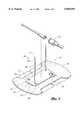
- FIG. 1is a perspective view of an anchoring system in accordance with a preferred embodiment of the present invention, together with an exemplary catheter and fluid tube coupling;
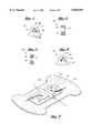
- FIG. 2is an exploded perspective view of the anchoring system and the catheter and fluid tube coupling of FIG. 1;
- FIG. 3is a side plane view of a receptacle of the anchoring system of FIG. 2 as viewed in the direction of line 3--3;
- FIG. 4is a cross-sectional view of the receptacle of FIG. 3 taken along line 4--4;
- FIG. 5is a cross-sectional view of a receptacle configured in accordance with another embodiment of the present invention.
- FIG. 6is a side elevational view of a receptacle configured in accordance with an additional embodiment of the present invention.
- FIG. 7is a perspective view of the anchoring system of FIG. 1 engaged with a conventional suture wing extension
- FIG. 8is a perspective view of an anchoring system configured in accordance with another preferred embodiment of the present invention, illustrated in connection with an exemplary box-type clamp;
- FIG. 9is a top plan view of a retention mechanism of the anchoring system of FIG. 8;
- FIG. 10is a perspective view of an anchoring system configured in accordance with an additional preferred embodiment of the present invention, illustrated in connection with an exemplary box-type clamp;
- FIG. 11is a top plan view of the anchoring system of FIG. 10, including a release layer attached to an adhesive pad of the anchoring system;
- FIG. 12is a partial cross-sectional, side elevational view of a retention mechanism and the adhesive pad of FIG. 11, taken along line 12--12;
- FIG. 13is a partial cross-sectional front elevational view of the retention mechanism and adhesive pad of FIG. 12, taken along line 13--13;
- FIG. 14is a cross-sectional view of a receptacle of the retention member of FIG. 12 with a portion of a filament of the retention member inserted into the receptacle;
- FIG. 15is a cross-sectional view of another embodiment of a receptacle which can be used with the anchoring system, such as that illustrated of FIG. 10;
- FIG. 16is a cross-sectional view of the receptacle of FIG. 16 with a tang member of the receptacle deflected;
- FIG. 17is a cross-sectional view of an additional embodiment of a receptacle which can be used with an anchoring system, such as that illustrated in FIG. 10.
- FIG. 1illustrates an anchoring system 10 which is configured in accordance with a preferred embodiment of the present invention and is used in connection with a catheter-fluid line connector 12 (e.g., a luer-lock connector).
- a catheter-fluid line connector 12e.g., a luer-lock connector
- the present anchoring system 10also can be successfully utilized in connection with other types of medical articles, such as for example, but without limitation, CVCs, PICCs, Foley catheters, and hemodialyses catheters, surgical drainage tubes, feeding tubes, chest tubes, nasogastric tubes, as well as with electrical wires or cables connected to external or implanted electronic devices or sensors.
- the term “medical article”is meant generically to include catheters, fluid supply and drainage lines, connectors, adaptors, electrical wires and cables, and the like, all of which may be retained by the present anchoring system 10. It therefore should be understood that the principles of the present invention are not limited to PICCs or central line catheters.
- the present anchoring system 10also can be used with non-medical articles as well.
- the anchoring system 10can be used to secure wires, tubing, cables and like articles to a support (e.g., a wall, stud, pipe, etc.). It is appreciated that those skilled in the art can readily adapt the illustrated embodiments of the present invention to suit any of a variety of non-medical applications.
- the anchoring system 10includes a retention mechanism 14 mounted on top of an anchor pad 16.
- the anchor pad 16includes a self-adhesive backing (not shown) to secure the retention mechanism 14 to the patient's skin.
- the retention mechanism 14includes at least one filament or thread 18 which cooperates with a corresponding receptacle 20. By means of cooperation between the filament 18 and the receptacle 20, as described below in more detail, the connector 12 can be conveniently and painlessly anchored to and released from the patient's skin.
- FIG. 1illustrates a longitudinal axis, a transverse axis and a lateral axis in relation to the anchoring system 10.
- the longitudinal axisextends in a direction generally parallel to an axis of the tube.
- the lateral axislies perpendicular to the longitudinal axis within the plane of the anchor pad 16.
- the transverse axisextends transverse to the longitudinal and lateral axes.
- the "longitudinal direction”refers to a direction substantially parallel to the longitudinal axis.
- the lateral direction and “the transverse direction”are in reference to the lateral axis and the transverse axis, respectively.
- the terms “proximal” and “distal”are also used to describe some of the components of the anchoring system 10. These terms are used in reference to the proximity of the base.
- the retention mechanism 14includes a base 22 and a pair of filaments 18 that extend from the base 22.
- the retention mechanism 14of course can include other numbers of filaments 18 in order to suit a specific application.
- Each filament 18includes a fixed proximal end 24, a free distal end 26 and at least one protuberance (generally indicated by reference numeral 28) positioned therebetween.
- the filaments 18can have a variety of lengths depending upon the particular application of the anchoring device 10. For use with anchoring catheters and medical tubings, each filament 18 desirably has a length of about 5 inches; however, much longer or short lengths also are possible.
- the filaments 18also can have a various diameter sizes depending upon the required strength of the filaments 18.
- each filament 18includes a plurality of protuberances 28 arranged in series between the distal end 26 and the proximal end 24 of the filament 18. It is contemplated, however, that the filaments 18 can be configured to allow a health care provider to form the protuberance 28 in the filament 18 by tying a knot toward the distal end 26 of the filament 18.
- each protuberance 28 of the filament 18has a generally conical shape with a maximum diameter at a proximal end of the protuberance 28.
- the protuberances 28can take a variety of other shapes, such as for example, hollow conical shapes, arrow shapes, or transverse rib-like shapes.
- the proximal end of each protuberance 28, however,desirably has a diameter which is larger than the diameter of the filament 18.
- the proximal end of each protuberance 28forms a flat surface that lies generally transverse to a longitudinal axis of the corresponding filament 18.
- the proximal end surface of some or all of the protuberancesalternatively can slope or project toward the distal end of the filament 18.
- the filament 18desirably includes a needle-like shaped distal portion 30 with a generally pointed, but blunt end portion 32 positioned at the distal end of the filament 18.
- the distal portion 30smoothly tapers with increasing diameter from the end 32 toward the distal-most protuberance 28.
- the diameter of the distal portion 30 at a point adjacent the distal-most protuberance 28desirably equals the diameter of the filament 18 proximal to the protuberances 28.
- the retention mechanism 14also includes at least one and preferably a plurality of receptacles 20 positioned on the base 22. Each receptacle 20 is arranged on the base 22 to cooperate with at least one filament 18, as discussed below.
- the receptacles 20receive the distal ends 26 of the filaments 18 in a manner permitting the insertion of the filament 18 into the receptacle 20, but inhibiting the retraction of the filament 18 from the receptacle 20.
- the corresponding filament 18 and receptacle 20include interengaging structure that allows the filament 18 to be easily inserted into the receptacle 20 in one direction with a first degree of force but prevents retraction of the filament 18 when a same or greater degree of force is applied to the filament 18 in the opposite direction. A larger degree of force is required to retract the filament 18 from the receptacle 20.
- the interengaging structure between the corresponding filament 18 and the receptacle 20comprises the protuberances on the filaments 18 and apertures 34 of the receptacles 20.
- the interengaging structures of the filament-receptacle pairingsare substantially identical, and the following description of one should be understood as applying equally to both, unless specified to the contrary.
- each aperture 34advantageously has a conical or funnel-like shape to help guide the distal end 32 of the filament distal portion 30 through the aperture 34.
- the aperture 34tapers from a large diameter on an inner side 35 of the receptacle to a smaller diameter of the outer side 37 of the receptacle 34.
- the smaller diameterdesirably is larger than the maximum diameter of the filament distal portion 30, but smaller than the maximum diameter of the protuberances 28.
- the receptaclealso can facilitate insertion from both sides of the receptacle, rather than the unidirectional configuration of the receptacle illustrated in FIG. 4.
- the receptaclecan have an hour-glass or double conical shape to help guide the distal end 32 of the filament through the aperture from either the inner side 35 or the outer side 37 of the receptacle 20.
- the aperture 34tapers from a larger diameter to a smaller diameter.
- the smaller diameter section of the apertureoccurs at the center of the receptacle's width, at a point equally distanced from the inner side 35 and the outer side 37 of the receptacle 20.
- the smaller diameterdesirably is larger than the maximum diameter of the filament distal portion 30, but smaller than the maximum diameter of the protuberances 28. Because the aperture tapers to the small diameter from either side 35, 37 of the aperture, the filament 18 can be easily inserted into the double-conical aperture 34 from either side.
- the receptacle 20 and/or the protuberances 28 of the associated filaments 18are configured such that a wall of the receptacle 20 about the aperture 34 and/or the protuberances 28 deflect to allow the larger diameter protuberances 28 to pass through the smaller diameter aperture 34 of the receptacle 20.
- the thin wall about the aperture 34 at its outer side 37, the thin peripheral thickness of the protuberance 28 at its proximal end, and the elastic nature of the plastic from which these components are formedprovides the required deflection necessary for the protuberances 28 to pass through the aperture 34.
- the receptacles 20can be configured to provide a convenient way to intentionally release the filament 18 from the receptacle 20.
- the receptaclecan include an opening or slit 44.
- the slit 44extends from the outer perimeter 46 of the wall 42 to the aperture 34, and desirably slopes toward the base 22.
- the slit 44has a gap spacing that is substantially smaller than the diameter of the aperture 34, and that is desirably smaller than a minimum diameter of the filament 18 (which occurs between adjacent protuberances 28).
- the slit 44 in the wall of the receptacle 20facilitates insertion of the filament 18 into the aperture 34 by providing flexibility to the receptacle wall 42 when the filament 18 is drawn through the aperture 34.
- the filamentalso can be removed from the aperture 34 by sliding a small diameter portion of the filament 18, which occurs between adjacent protuberances 28, into the slit 44. Further transverse movement (i.e., movement in a direction which is transverse to the direction of insertion into the receptacle 20) of the filament 18 slides the filament 18 out of the aperture 34 through the slit 44.
- the configuration of the slit 44requires that the transverse movement occur under a deliberate force.
- the small size of the slit 44 relative to the diameter of the filament 18, and the sharp transition edges between the diameter of the aperture 34 and the slit 44mandate that a transverse force of sufficient strength to deflect the upper portion of the receptacle away the base 22, be applied in order to move the filament 18 in the transverse direction.
- the sloping orientation of the slit 44 toward the patientmakes it unlikely that such a sufficient transverse force could be applied unintentionally. Rather, a health care provider must intentionally move the filament 18 in this direction through the slit 44.
- each filament 18 and corresponding receptacle 20are positioned on opposite sides of the base 22.
- the filaments 18also are positioned on opposite sides of the base 22 from each other, and the receptacles 20 are positioned on opposite sides of the base 22 from each other.
- the filaments 18 and the receptacles 20advantageously are placed proximate to the comers of the base 22 with the filaments 18 positioned diagonally across the base 22 from each other and the receptacles 20 positioned diagonally across the base 22 from each other.
- the base 22, filaments 18 and receptacles 20 of the retention mechanism 14desirably are integrally formed together. This can be accomplished in any of a variety of ways which will be well known to one of skill in the art. For instance, the entire retention mechanism 14 can be integrally molded of plastic or nylon by injection molding.
- the retention mechanism 14desirably is secured to the anchor pad 16 by means of a solvent bond adhesive.
- a suitable adhesiveis available commercially from the Minnesota Mining and Manufacturing Company (3M, Part No. 4693.
- the flexible anchor pad 16comprises a layer of closed-cell, low-density polyethylene foam (LDPE) and a bottom adhesive mono-layer of medical-grade adhesive.
- the adhesivecan be either diaphoretic or nondiaphoretic, depending upon the particular application.
- the foam layer with the adhesive bottom surfaceis available commercially from New Dimensions in Medicine of Columbus, Ohio.
- An upper surface of the foam layeris energized by corona treating the foam with a low electric charge, as known in the art.
- the corona-treated upper surface of the anchor pad 16improves adhesion when attaching the retention mechanism 14 to the anchor pad 16.
- a removable paper or plastic backing 36desirably covers the bottom adhesive surface before use.
- the backingpreferably resists tearing and is divided into a plurality of pieces to ease attachment of the pad 16 to the patient's skin.
- the backing 36is split along a center line of the flexible anchor pad 16 in order to expose only half of the adhesive bottom surface at one time.
- the backing 36also advantageously can extend beyond at least one edge of the anchor pad 16 to ease removal of the backing from the adhesive layer. Such an extension of the backing 36 forms a tab which a health care provider can easily grip and remove while wearing protective gloves.
- the health care providerinitially selects a skin site on which the anchoring system 10 will be attached.
- the anchoring system 10desirably is applied to the skin of the patient in the vicinity of the catheter insertion site.
- the health care providercleanses and prepares the anticipated dressing site per hospital or agency protocol, usually using alcohol. The alcohol should be allowed to dry thoroughly. The health care provider then removes the anchor pad 16 from its packaging (not shown) and properly locates the pad 16 on the patient. The anchor pad 16 should be mounted on the patient so that the filaments 18 and the receptacles 20 are positioned on either side of the connector 12 or the catheter, and lie directly under the connector 12 or catheter.
- the health care providerpeels away the backing 36 from one half of the anchor pad 16 while pressing the exposed adhesive surface against the patient's skin. This process is repeated with the other half of the anchor pad 16. The pad 16 is pressed against the patient's skin to secure the anchor pad 16 to the patient. The health care provider is now ready to secure the tube connector 12 or catheter to the patient.
- the first filament 18is wrapped around one side of the connector 12 and is threaded through the opposing receptacle 20.
- the filament 18has a sufficiently long length to wrap around the connector 12 and easily threaded through the receptacle 20.
- the distal end 26 of the filament 18threads into the receptacle aperture 34 easily.
- the conical shape of the aperture 34helps guide the distal portion 30 through the receptacle 20.
- the conical shape of the protuberances 28further ease insertion of the filament 18 through the aperture 34, as described above.
- the flat proximal end of the protuberance 28engages the outer surface 37 of the receptacles 20 and inhibits retraction of the filament 18 from the receptacle 20.
- the health care providerlikewise wraps the second filament 18 around the other side of the fluid line connector 12 and then inserts the distal end 26 into the opposing receptacle 20.
- the insertion process of the second filament 28 into the corresponding receptacle 20is accomplished in the manner described above.
- the health care providerpulls both filaments 18 tight to draw the fluid line connector 12 against the base 22. Excess filament length can be severed or cut distal to the receptacle 20.
- the health care providerthen can complete insertion site dressing per established hospital/agency dressing protocol.
- the taut filaments 18prevent the fluid line connector 12 from moving transversely away from the base 22 and from sliding either longitudinally or laterally over the base 22. In this manner, the anchoring system 10 assists maintaining the connection between the catheter and fluid line established by the connector 12.
- the anchoring system 10can be used to secure a variety of tubings or catheters, independent of a connector, to the patient.
- the securement devicecan be used with nasogastric tubes, Foley catheters, surgical drainage tubes, chest tubes and feeding tubes.
- the filamentsare wrapped around directly the tube or catheter and then inserted into the corresponding receptacle, as described above.
- FIG. 7also illustrates that the present anchoring system 10 can be used to secure to a patient a conventional clamp with suture wing extensions 38, such as, for example, that used with a Quinton® Hemodialysis catheter, a Cook® PICC, a steel needle, or a Huber® needle, a conventional rigid fastener/flexible clamp combination (see FIG. 10), such as, for example, that used with a Arrow® CVC, or another type suture seat, such as, for example, that used with the Baxter® Triple Lumen (not illustrated).
- the catheter wingsdo not include suture holes, the health care provider can form holes in the winged extensions with a punch.
- a health care providerplaces the suture wing extensions 38 on the base 22 between the filaments 18 and receptacles 20.
- One of the filaments 18is threaded through the closest suture hole 40 of the suture wing and threaded through the adjacent receptacle 20.
- the health care providerinserts the second filament 18 through the corresponding suture hole 40 and receptacle 20.
- the interengaging structures of the filaments 18 and the corresponding receptacles 20prevent unintentional disengagement of the filaments 18 from the receptacles 20.
- the anchoring system 10additionally can be used with catheters including suture grooves.
- the health care providerwraps at least one of the filaments 18 around the groove which is provided on the catheter hub.
- the filaments 18are then threaded through the opposite receptacles 20 and pulled taut.
- the health care providercompletes the insertion site dressing in the manner described above.
- each filament 18can be inserted into either receptacle 20 to permit the anchoring system 10 to be used with more than one type of medical article.
- the filament 18when used with the opposing receptacle 20, the filament 18 can be wrapped around a portion of the medical article and threaded through the corresponding receptacle 20.
- the filament 18engages the structure on one side of the medical article and then can be threaded through the receptacle 20 on the same side of the retention mechanism 14.
- Other arrangements of the filaments 18 and receptacles 20which will be readily apparent to those skilled in the art also are possible in order for the anchoring system 10 to be used with other types of medical articles.
- the health care providerWhen removal becomes necessary, the health care provider carefully removes any insertion site dressings which cover the anchoring system 10 and carefully snips the filaments 18 at a point between the proximal end 24 of the filament 18 and the corresponding receptacle 20 using a blunt hemostat. The medical article then can be lifted from the base 22 and the filaments 18 removed from the article. To remove the anchor pad 16, the health care provider lifts an edge of the pad 16 and gently strokes the undersurface with an alcohol swab while slowly but continuously lifting the edge. The anchor pad 16 can be peeled from the patient's skin in this manner. The health care provider then cleanses and prepares skin per hospital/agency protocol.
- the anchor pad 16absorbs any forces which are incurred in the installation or removal of the anchoring system 10 and the medical device, thereby providing greater comfort for the patient.
- FIGS. 8 and 9illustrate an anchoring system configured in accordance with another preferred embodiment of the present invention. Only the construction of the retention mechanism of this embodiment differs from the above-described embodiment. Accordingly, the above description should apply equally to the embodiment of FIGS. 8 and 9, unless indicated otherwise.
- like reference numerals with an "a" suffixhave been used to indicate like components between these embodiments to easy the reader's understanding.
- the retention member 14aincludes at least one filament 18a and at least one receptacle 20a which are attached to the base 22a.
- the filament 18a and corresponding receptacle 20ainclude interengaging structure which connects the filament 18a to the receptacle 20a when the filament 18a is drawn through the receptacle 20a.
- the retention member 14aincludes a two filament and receptacle pairings; however, the retention member 14a can include any number of pairings to suit a particular application.
- the retention member 14adesirably is formed from a single flat sheet of material.
- the retention member 14acan be formed in a variety of way known to those skilled in the art, the retention member 14a desirably is die cut from a sheet of nylon.
- Other materialsalso can be used; however, the material should be sufficiently pliable to allow the filaments 18a and the receptacles 20a to be easily moved out of the plane of the base 22a in order to engage one another, and thus secure the medical device to the base 22a, in the manner described below.
- each filament 18ainitially lies within the plane of the base 22a and is integrally formed with the base 22a.
- each receptacle 20ainitially lies within the plane of the base 22a and is integrally formed with the base 22a.
- the filaments 18aare positioned across from each other at diagonal comers of the base 22a and the receptacles 20a also are position across from each other at diagonal comers of the base 22a.
- the retention mechanism 14acan include other arrangements of the filaments 18a and the receptacles 20a on the base 22a.
- Each filament 18aextends outwardly from the corner of the base 22a, but in a diagonal direction toward the end of the base 22a on which the corresponding receptacle 20a is positioned.
- the filament 18ahas a fixed proximal end 24a (i.e., the end closest to the base 22a) and a free distal end 26a.
- a series of protuberances 28aare formed toward the distal end 26a.
- the protuberances 28aare a plurality of barbs which lie in series. Except for the distal most barb, each barb 28a has truncated triangular shape.
- the distal-most barb 28aincludes a tapered, blunt end 32a which helps guide the filament 18a into the corresponding receptacle 20a.
- each filaments 18acan be bent at its proximal end out of the plane of the base 22a.
- the filament 18athen can be extended to the corresponding receptacle 20a, as described below.
- Each receptacle 20aincludes an aperture 34a that receives the distal barbed portion of the corresponding filament 18a.
- the aperture 34ahas a size larger than the distal end 26a of the filament 18a, but smaller than the maximum width of the barbs 28a.
- the barbs 28aconsequently pass through the aperture 34a in a ratchet-like manner to inhibit retraction of the filament 18a from the receptacle 20a.
- each aperture 34ahas an elliptical shape.
- the major axis of the aperture 34agenerally lies parallel to an axis of the corresponding filament 18a. This orientation of the aperture 34a reduces filament twisting when inserted into the receptacle 20a.
- Each receptacle 20ahas a tab-like shape which can be bent out of the plane of the base 22a.
- the health care providercan easily insert the distal end 26a of the corresponding filament 18a into the aperture 34a with the receptacle 34a pulled away from the anchor pad 16a.
- FIG. 8illustrates an application of the present anchoring device with a conventional flexible clamp/rigid fastener combination ("a conventional catheter box clamp").
- a conventional catheter box clampThis application, however, is merely exemplary.
- the present anchoring system 10acan be used with any of a variety of medical device in the manner described above.
- the box clamp 48a having wing extensions 38ais placed generally at the center of the base 22a, between the filaments 18a and the receptacles 20a.
- One of the filaments 18ais threaded through the closest suture hole 40a of the clamp 48a and then is threaded through the adjacent receptacle 20a.
- the second filament 18ais threaded through the corresponding suture hole 40a and receptacle 20a.
- the filaments 18a and the corresponding receptacles 20aengage with the barbs 28a ratcheting through the apertures 34a, to secure the catheter clamp 48a to the base 22a and to inhibit unintentional disengagement of the filaments 18a and the receptacles 20a.
- FIGS. 10-14illustrate an anchoring system configured in accordance with an additional preferred embodiment of the present invention. Again, only the construction of the retention member of this embodiment differs from the above-described embodiment of FIGS. 1-4. Accordingly, the above description should apply equally to the embodiment of FIGS. 10-14, unless indicated otherwise.
- like reference numerals with a "b" suffixare used to indicate like components between these embodiments to easy the reader's understanding.
- the retention mechanism 14bincludes at least one filament or thread 18b which cooperates with a corresponding receptacle 20b.
- the retention mechanism 14bincludes a base 22b and a pair of filaments 18b that extend from the base 22b.
- the retention mechanism 14bof course can include other numbers of filaments 18b in order to suit a specific application.
- Each filament 18bincludes a fixed proximal end 24b, a free distal end 26b and at least one protuberance (generally indicated by reference numeral 28b) positioned therebetween.
- each filament 18bincludes a plurality of protuberances 28b arranged in series between the distal end 26b and the proximal end 24b of the filament 18b.
- each protuberance 28b of the filament 18bhas a generally conical shape with a maximum diameter D at a proximal end of the protuberance 28b.
- the protuberances 28bcan take a variety of other shapes, such as for example, hollow conical shapes, arrow shapes, or transverse rib-like shapes.
- the proximal end of each protuberance 28bdesirably has a diameter D which is larger than a minimum diameter d of the filament 18b.
- each protuberance 28bforms a flat surface that lies generally transverse to a longitudinal axis of the corresponding filament 18b.
- the proximal end surface of some or all of the protuberancesalternatively can slope or project toward the distal end of the filament 18b.
- the filament 18bdesirably includes a needle-like shaped distal portion 30b with a generally pointed, but blunt end 32b positioned at the distal end of the filament 18b.
- the needle-like shape of the distal end portion 30btends to make the use of the filament 18b intuitive to a health care provider.
- the distal end portion 30balso is substantially rigid to ease insertion of the distal end 30b through the receptacle 20b.
- the filaments 18bcan have a variety of lengths depending upon the particular application of the anchoring device 10b.
- each filament 18bdesirably has a length of about 5 inches; however, much longer or short lengths also are possible.
- the filaments 18balso can have a various diameter sizes depending upon the required strength of the filaments 18b.
- the retention mechanism 14balso includes at least one and preferably a plurality of receptacles 20b positioned on the base 22b. Each receptacle 20b is arranged on the base 22b to cooperate with at least one filament 18b, as discussed below.
- the receptacles 20breceive the distal ends 26b of the filaments 18b in a manner permitting the insertion of the filament 18b into the receptacle 20b, but inhibiting the retraction of the filament 18b from the receptacle 20b.
- the corresponding filament 18b and receptacle 20binclude interengaging structure that allows the filament distal end 26b to be easily inserted into the receptacle 20 in one direction with a first degree of force but prevents retraction of the filament distal end 26b when a same or greater degree of force is applied to the filament 18b in the opposite direction. A larger degree of force is required to retract the filament 18b distal end from the receptacle 20b.
- the interengaging structure between the corresponding filament 18b and receptacle 20bcomprises the protuberances 28b on the filament 18b and a trap device 50 of the receptacle 20b. Because the interengaging structure of the filament-receptacle pairings are substantially identical, the following description of one should be understood to apply equally to both, unless specified to the contrary.
- each trap device 50has a conical or funnel-like shape to help guide the distal end 26b of the filament 18b into the trap device 50.
- Trap device 50tapers from a large diameter 52 on one side of the receptacle 20b to a smaller diameter 54 on the other side of the receptacle 20b.
- the large diameter 52is larger than the maximum diameter of the filament 18b (i.e., the maximum diameter of the protuberances 28b).
- the smaller diameter 54desirably is smaller than the tip 32b of the filament distal end 26b to facilitate insertion of the filament 18b through the trap device 50.
- the smaller diameter 54is smaller than the maximum diameter of the protuberances 28b, which in the illustrated embodiment, occurs at the proximal ends of the protuberances 28b.
- the trap device 50is formed by a plurality of flexible fingers 56.
- three fingers 56form the trap device 50.
- the fingers 56extend from a lug 58 of the receptacle 20b at positions about the periphery of an aperture 60 through the lug 58.
- the fingers 56converge toward the smaller diameter end 54 of the trap device 50.
- the gap spacingsallow the fingers 56 to deflect in the radial direction away from the insertion axis through the trap device 50.
- the protuberance 28bforces the fingers 56 apart as it passes through the trap device 50.
- the fingers 56spring back to a diameter that is smaller than the diameter D of the flat proximal end of the protuberance 28b. In this manner, the cooperation between the trap device 50 and the protuberances 28b allows insertion of the filament 18b through the receptacle 20b in one direction, but inhibits retraction of the filament 18b.
- the trap devices 50 of the receptacles 20bface in the same direction. This arrangement simplifies the manufacture of the retention mechanism 14. It is understood, however, that the trap devices 50 can face in opposite directions in order to suit specific applications.
- FIGS. 15 and 16illustrate an exemplary release mechanism.
- the finger 56 near the base 22bincludes tab 62.
- the tab 62desirably extends laterally to both sides of the receptacle 20b to ease manipulation of the tap 62.
- a health care providercan place one finger on one side of the filament 18b and another finger on the opposite side of the filament 18b and depress the tap 62.
- FIG. 16illustrates the tab 62 when depressed.
- the smaller end opening 52enlarges with the tab 62 depressed to a size larger than the maximum diameter D of the protuberance 28b.
- the health care providerthus can withdraw the filament 18b from the trap device 50 with the release mechanism actuated in this manner.
- FIG. 17illustrates another embodiment of the release mechanism with the tab 62 positioned on the upper side of the retainer lug 58. Downward deflection of the tab 56 causes the upper finger 56 to rise up. The smaller end opening 56 consequently enlarges to a size which facilitates retraction of the filament 18b, as described above.
- the receptacles 20b and the filaments 18bdesirably lie along a common line L, preferably along a center line of the base 22b in the lateral direction.
- This arrangementfacilitates manufacture of the retention mechanism 14b by injection molding and allows the part to be made within only a two piece mold (which is significantly less expensive than multiple piece molds).
- the base 22bhas a generally rectangular shape with the long sides of the base 22b being concave.
- the filaments 18blie inside the receptacles 20b and are spaced apart by a distance sufficient to receive the particular medical article to be anchored (e.g., a box clamp as illustrated in FIG. 10). The spacing between the filaments 18b of course can vary depending upon the particular article which the anchoring device 10b is designed to be used.
- the retention mechanism 14bdesirably is formed of a material having suitable flexibility to allow for the above-described operation of the trap device 50, as well as for the above-described operation of the release mechanism, should the retention mechanism 14b include such a mechanism. It also is desired that the retention mechanism 14b be injected molded in order to reduce fabrication costs. For these purposes, the retention mechanism 14b desirably is molded of a super tough nylon, such as that available commercially from DuPont, Part No. SP801, or of a polypropylene.
- the retention mechanism 14bdesirably is secured to the anchor pad 16b by means of a solvent bond adhesive.
- a suitable adhesiveis available commercially from the Minnesota Mining and Manufacturing Company (3M), Part No. 4693.
- the flexible anchor pad 16bcomprises a layer of closed-cell, low-density polyethylene foam (LDPE) and a bottom adhesive mono-layer of medical-grade adhesive.
- the adhesivecan be either diaphoretic or nondiaphoretic, depending upon the particular application.
- the foam layer with the adhesive bottom surfaceis available commercially from New Dimensions in Medicine of Columbus, Ohio.
- An upper surface of the foam layeris energized by corona treating the foam with a low electric charge, as known in the art.
- the corona-treated upper surface of the anchor pad 16bimproves adhesion when attaching the retention mechanism 14b to the anchor pad 16b.
- a releasible backingdesirably covers the adhesive layer of the anchor pad 16b before application.
- the present inventionprovides a sterile, tight-gripping, needle-free way to secure medical articles to a patient.
- the anchoring systemthus eliminates accidental needle sticks and suture wound site infections and scarring because sutures are not required.
- the anchoring systemcan be used with any of a wide variety of catheters, tubes, wires, and other medical articles to provide universal securement using one style of securement device. Also, patient comfort enhances and application time decreases with the use of the present anchoring system.
- the present anchoring systemalso can be used in non-medical applications.
- the anchoring systemcan secure items such as, for example, electrical wires, tubing, cables, etc., to a support structure.
- the components of the anchoring deviceneed not be made of medical-grade materials.
- an adhesive tapee.g., conventional duct tape
- the retention mechanismcan be applied directly to the non-adhesive side of the tape.
- the adhesive surface of the tapeis intended to secure the retention mechanism to the support.
Landscapes
- Health & Medical Sciences (AREA)
- Life Sciences & Earth Sciences (AREA)
- Biophysics (AREA)
- Pulmonology (AREA)
- Engineering & Computer Science (AREA)
- Anesthesiology (AREA)
- Biomedical Technology (AREA)
- Heart & Thoracic Surgery (AREA)
- Hematology (AREA)
- Animal Behavior & Ethology (AREA)
- General Health & Medical Sciences (AREA)
- Public Health (AREA)
- Veterinary Medicine (AREA)
- Media Introduction/Drainage Providing Device (AREA)
- Ultra Sonic Daignosis Equipment (AREA)
- Surgical Instruments (AREA)
- Materials For Medical Uses (AREA)
Abstract
Description
Claims (53)
Priority Applications (2)
| Application Number | Priority Date | Filing Date | Title |
|---|---|---|---|
| US08/689,314US5855591A (en) | 1995-08-07 | 1996-08-07 | Catheter securement device |
| US09/133,710US6117163A (en) | 1995-08-07 | 1998-08-13 | Catheter securement device |
Applications Claiming Priority (2)
| Application Number | Priority Date | Filing Date | Title |
|---|---|---|---|
| US08/512,082US5637098A (en) | 1995-08-07 | 1995-08-07 | Catheter securement device |
| US08/689,314US5855591A (en) | 1995-08-07 | 1996-08-07 | Catheter securement device |
Related Parent Applications (2)
| Application Number | Title | Priority Date | Filing Date |
|---|---|---|---|
| US08/512,082Continuation-In-PartUS5637098A (en) | 1995-08-07 | 1995-08-07 | Catheter securement device |
| US08/512,082ContinuationUS5637098A (en) | 1995-08-07 | 1995-08-07 | Catheter securement device |
Related Child Applications (1)
| Application Number | Title | Priority Date | Filing Date |
|---|---|---|---|
| US09/133,710ContinuationUS6117163A (en) | 1995-08-07 | 1998-08-13 | Catheter securement device |
Publications (1)
| Publication Number | Publication Date |
|---|---|
| US5855591Atrue US5855591A (en) | 1999-01-05 |
Family
ID=24037592
Family Applications (3)
| Application Number | Title | Priority Date | Filing Date |
|---|---|---|---|
| US08/512,082Expired - LifetimeUS5637098A (en) | 1995-08-07 | 1995-08-07 | Catheter securement device |
| US08/689,314Expired - LifetimeUS5855591A (en) | 1995-08-07 | 1996-08-07 | Catheter securement device |
| US09/133,710Expired - LifetimeUS6117163A (en) | 1995-08-07 | 1998-08-13 | Catheter securement device |
Family Applications Before (1)
| Application Number | Title | Priority Date | Filing Date |
|---|---|---|---|
| US08/512,082Expired - LifetimeUS5637098A (en) | 1995-08-07 | 1995-08-07 | Catheter securement device |
Family Applications After (1)
| Application Number | Title | Priority Date | Filing Date |
|---|---|---|---|
| US09/133,710Expired - LifetimeUS6117163A (en) | 1995-08-07 | 1998-08-13 | Catheter securement device |
Country Status (9)
| Country | Link |
|---|---|
| US (3) | US5637098A (en) |
| EP (1) | EP0846013B1 (en) |
| JP (2) | JP3985056B2 (en) |
| CN (1) | CN1167475C (en) |
| AT (1) | ATE258815T1 (en) |
| AU (1) | AU721160B2 (en) |
| CA (2) | CA2228747C (en) |
| DE (1) | DE69631481T2 (en) |
| WO (1) | WO1997005920A1 (en) |
Cited By (48)
| Publication number | Priority date | Publication date | Assignee | Title |
|---|---|---|---|---|
| WO2002019916A1 (en)* | 2000-09-07 | 2002-03-14 | Cloud William G M D | Mesh material to repair hernias |
| US6572587B2 (en) | 2000-01-10 | 2003-06-03 | Benjamin S. Lerman | Anchoring device for medical apparatus |
| US6582403B1 (en) | 2000-02-24 | 2003-06-24 | Venetec International, Inc. | Universal catheter anchoring system |
| US6770055B2 (en) | 2000-02-24 | 2004-08-03 | Venetec International, Inc. | Universal catheter anchoring system |
| WO2005023333A3 (en)* | 2003-09-04 | 2005-05-12 | Roy Raghunandan | Supercutaneous method and device for promoting hemostasis in cannulated patient |
| US20050113759A1 (en)* | 2003-11-24 | 2005-05-26 | Mueller Richard L.Jr. | Catheter retainer |
| US20050192540A1 (en)* | 2004-02-26 | 2005-09-01 | Alan Kessler | Securement device for indwelling catheters or introducers |
| US7014627B2 (en) | 2002-08-15 | 2006-03-21 | Venetec International, Inc. | Catheter securement device |
| US20060229676A1 (en)* | 2003-10-24 | 2006-10-12 | Frank Doll | Device for fixing and tensioning at least one pulling thread for applying a neovagina |
| US20060247577A1 (en)* | 2005-04-19 | 2006-11-02 | Wright Clifford A | Flexible IV site protector |
| US20060264836A1 (en)* | 2005-05-18 | 2006-11-23 | Bierman Steven F | Insertion site protection device |
| US20060270995A1 (en)* | 2005-05-26 | 2006-11-30 | Bierman Steven F | Anchoring system for use with neonates |
| US20060276752A1 (en)* | 2005-05-23 | 2006-12-07 | Bierman Steven F | Medical article anchoring system |
| US20070055205A1 (en)* | 2005-07-14 | 2007-03-08 | Wright Clifford A | Protective dressing and methods of use thereof |
| US20070276331A1 (en)* | 2006-05-24 | 2007-11-29 | Helen Campbell | Device for retaining the external portion of a peripherally inserted central catheter |
| US20080066265A1 (en)* | 2006-09-15 | 2008-03-20 | Pilon Roger E | Break-away bundling device |
| US20080249476A1 (en)* | 2005-08-31 | 2008-10-09 | Venetec International, Inc. | Anchoring System For a Catheter |
| US20090137962A1 (en)* | 2007-07-16 | 2009-05-28 | C.R. Bard, Inc. | Securement system employing polymeric gel |
| US20090326474A1 (en)* | 2008-06-26 | 2009-12-31 | Venetec International, Inc. | Universal strap device |
| US20100022962A1 (en)* | 2008-07-23 | 2010-01-28 | Venetec International, Inc. | Securement device |
| US20110098654A1 (en)* | 2009-10-27 | 2011-04-28 | Russell Shipman | Anchoring And Protective Intravenous Shield |
| US20110218498A1 (en)* | 2008-08-06 | 2011-09-08 | Venetec International, Inc. | Cleated anchoring system |
| US8146210B2 (en) | 2007-07-17 | 2012-04-03 | C.R. Bard, Inc. | Support clamp for medical line |
| US8556859B2 (en) | 2011-12-21 | 2013-10-15 | Securcath LLC | Securement device for medical fixtures |
| US8679066B2 (en) | 2009-05-15 | 2014-03-25 | C.R. Bard, Inc. | Stabilization device with integrated dressing |
| US8734400B2 (en) | 2008-09-19 | 2014-05-27 | C.R. Bard, Inc. | Medical device securement system |
| US8740852B2 (en) | 2009-08-25 | 2014-06-03 | C. R. Bard, Inc. | Medical article securement device |
| US8834426B2 (en) | 2009-10-27 | 2014-09-16 | Russell Shipman | Catheter and tubing restraining device and protective cover |
| US8900196B2 (en) | 2011-04-21 | 2014-12-02 | C. R. Bard, Inc. | Anchoring system |
| US20150265808A1 (en)* | 2014-01-27 | 2015-09-24 | Amparo Medical Technologies, Inc. | Medical device securement system and method |
| US9261224B2 (en)* | 2012-08-17 | 2016-02-16 | David William Harris | Garment hanger collection apparatus |
| US9616200B2 (en) | 2005-12-21 | 2017-04-11 | Venetc International, Inc. | Intravenous catheter anchoring device |
| US9694130B2 (en) | 2009-10-06 | 2017-07-04 | Venetec International, Inc. | Stabilizing device having a snap clamp |
| US9700700B2 (en) | 2010-03-03 | 2017-07-11 | Venetec International, Inc. | Medical article with rotatable wings |
| US9731097B2 (en) | 2009-10-06 | 2017-08-15 | Venetec International, Inc. | Stabilizing device having a locking collet |
| US9895514B2 (en)* | 2014-01-27 | 2018-02-20 | Maddoc Medical Products, Inc. | Medical device securement system and method |
| US9962524B2 (en) | 2011-03-11 | 2018-05-08 | Venetec International, Inc. | Medical article securement device |
| US9993619B2 (en) | 2007-07-17 | 2018-06-12 | C. R. Bard, Inc. | Securement system for a medical article |
| US10322262B2 (en) | 2009-05-21 | 2019-06-18 | C. R. Bard, Inc. | Medical device securement system |
| US11020565B2 (en) | 2010-07-30 | 2021-06-01 | C. R. Bard, Inc. | Securement device |
| USD934433S1 (en) | 2020-06-01 | 2021-10-26 | 3M Innovative Properties Company | Medical tape strip |
| USD964571S1 (en) | 2019-05-28 | 2022-09-20 | Maddoc Medical Products, Inc. | Catheter securement pad |
| US11452848B2 (en) | 2019-04-17 | 2022-09-27 | Bard Access Systems, Inc. | Catheter securement device including extended anchor pad and release liner clasping features |
| USD975855S1 (en) | 2021-03-25 | 2023-01-17 | Maddoc Medical Products, Inc. | Catheter securement pad |
| WO2023022246A1 (en)* | 2021-08-18 | 2023-02-23 | (주)제이엠바이오텍 | Tube fixing device |
| US11648377B2 (en) | 2016-05-13 | 2023-05-16 | C. R. Bard, Inc. | Catheter securement device including a guiding nose |
| GB2619937A (en)* | 2022-06-21 | 2023-12-27 | Create Surgical Ltd | Surgical dressing |
| US12059536B2 (en) | 2019-02-01 | 2024-08-13 | Becton, Dickinson And Company | Stabilization device, system, and methods thereof for integrated catheters |
Families Citing this family (148)
| Publication number | Priority date | Publication date | Assignee | Title |
|---|---|---|---|---|
| USD401330S (en) | 1997-01-17 | 1998-11-17 | Pamela Jo Wright-Owens | Catheter security belt |
| USD395505S (en) | 1997-02-03 | 1998-06-23 | Noonan Joseph F | Catheter holder |
| US5792115A (en)* | 1997-04-30 | 1998-08-11 | Horn; John Russell | Apparatus and method for anchoring a catheter to the body of an individual |
| JP4544741B2 (en)* | 1997-10-01 | 2010-09-15 | ボストン サイエンティフィック リミテッド | Percutaneous catheter with slip hub |
| US6361523B1 (en) | 1998-03-27 | 2002-03-26 | Venetec International, Inc. | Anchoring system for a medical article |
| US6132398A (en)* | 1997-10-17 | 2000-10-17 | Venetec International, Inc. | Medical tubing securement system |
| US6328038B1 (en) | 1998-07-14 | 2001-12-11 | Fred Bruce Kessler | Nasal cannula retainer |
| US20020157673A1 (en)* | 1998-07-14 | 2002-10-31 | Kessler Fred B. | Nasal cannula retainer |
| US20020120231A1 (en)* | 2000-01-18 | 2002-08-29 | Douglas Joel S. | Subcutaneous injection set with secondary injection septum |
| US6749589B1 (en) | 2000-01-18 | 2004-06-15 | Sterling Medications, Inc. | Subcutaneous injection set for use with a reservoir that has a septum |
| US6572588B1 (en) | 2000-03-10 | 2003-06-03 | Venetec International, Inc. | Medical anchoring system |
| US6551285B1 (en)* | 2000-06-08 | 2003-04-22 | Venetec International, Inc. | Medical line securement device for use with neonates |
| IL157561A0 (en)* | 2001-03-04 | 2004-03-28 | Sterling Medivations Inc | Infusion hub assembly and fluid line disconnect system |
| US7150737B2 (en)* | 2001-07-13 | 2006-12-19 | Sci/Med Life Systems, Inc. | Methods and apparatuses for navigating the subarachnoid space |
| US7011647B2 (en)* | 2001-07-13 | 2006-03-14 | Scimed Life Systems, Inc. | Introducer sheath |
| WO2003011357A2 (en) | 2001-07-27 | 2003-02-13 | Saab Mark A | Medical device with adjustable epidermal tissue ingrowth cuff |
| US7736336B2 (en)* | 2001-09-13 | 2010-06-15 | Allegiance Corporation | Paracentesis device having multiple detachable components |
| EP2111885B1 (en)* | 2002-02-04 | 2011-09-21 | Becton, Dickinson and Company | Device and method for delivering or withdrawing a substance through the skin |
| USD470936S1 (en) | 2002-02-19 | 2003-02-25 | Venetec International, Inc. | Anchor pad |
| USD492411S1 (en) | 2003-04-14 | 2004-06-29 | Venetec International, Inc. | Anchor pad |
| US7413561B2 (en)* | 2003-08-13 | 2008-08-19 | Medical Components, Inc. | Conduit retaining clip |
| US7309326B2 (en)* | 2003-11-18 | 2007-12-18 | Icu Medical, Inc. | Infusion set |
| USD503977S1 (en) | 2004-01-23 | 2005-04-12 | Venetec International, Inc. | Anchor pad |
| US8012130B2 (en)* | 2004-03-12 | 2011-09-06 | Lina Medical Aps | Plaster device for supporting a bended length of a tube |
| WO2005092423A1 (en)* | 2004-03-12 | 2005-10-06 | Lina Medical Aps | A plaster device for supporting a bended length of a tube |
| US20050234405A1 (en)* | 2004-04-16 | 2005-10-20 | Dikeman W C | Site securement device for securing intravascular tubing |
| CA2573458C (en)* | 2004-07-14 | 2011-12-06 | Medical Components, Inc. | Catheter hub clip |
| USD552732S1 (en)* | 2005-07-13 | 2007-10-09 | Venetec International, Inc. | Anchor pad |
| US8052649B2 (en) | 2005-09-19 | 2011-11-08 | Venetec International, Inc. | Medical tubing securement assembly and methods of use |
| US7762986B2 (en)* | 2005-11-15 | 2010-07-27 | Biotop Holding Co., Ltd. | Safety container for a scalp vein needle |
| US8052648B2 (en) | 2005-12-21 | 2011-11-08 | Venetec International, Inc. | Intravenous catheter anchoring device |
| US9138560B2 (en) | 2006-01-12 | 2015-09-22 | Venetec International, Inc. | Universal catheter securement device |
| USD547862S1 (en) | 2006-02-06 | 2007-07-31 | Nexus Medical, Llc | Adhesive patient-contact strip for intravenous catheter anchoring devices |
| US7892216B2 (en)* | 2006-02-07 | 2011-02-22 | Icu Medical, Inc. | Infusion set |
| EP2007454A2 (en)* | 2006-04-07 | 2008-12-31 | Venetec International, Inc. | Side loaded securement device |
| US7806873B2 (en) | 2006-07-13 | 2010-10-05 | Venetec International, Inc. | Intravenous securement device with adhesively interconnected anchoring component and permeable adhesive strip |
| WO2008127153A1 (en)* | 2007-04-12 | 2008-10-23 | Atos Medical Ab | Method and device for supporting and retaining medical appliances |
| US8105290B2 (en) | 2007-06-01 | 2012-01-31 | Venetec International, Inc. | Universal catheter securement device |
| US8241253B2 (en) | 2007-07-20 | 2012-08-14 | C.R. Bard, Inc. | Securement system for a medical article |
| US20100179481A1 (en)* | 2007-09-10 | 2010-07-15 | Venetec International, Inc. | Securement device for a neonate |
| US20090112301A1 (en)* | 2007-10-25 | 2009-04-30 | Kowalczyk James M | Strain Relief System For Spinal Cord Stimulation Lead |
| US20090131919A1 (en)* | 2007-11-21 | 2009-05-21 | Christopher Davey | Implantable medical device |
| US8277420B2 (en)* | 2008-06-09 | 2012-10-02 | Venetec International, Inc. | Securement device with toggle clamp mechanism |
| US9480821B2 (en) | 2008-06-30 | 2016-11-01 | Venetec International, Inc. | Anchoring system for a medical article |
| US8075531B2 (en) | 2008-07-16 | 2011-12-13 | Marvao Medical Ltd. | Modular implantable medical device |
| US20100100049A1 (en)* | 2008-10-22 | 2010-04-22 | Godfrey Mark W | Securement device for vascular access system |
| US8617116B2 (en)* | 2009-03-27 | 2013-12-31 | Marvao Medical Devices Ltd. | Deformable medical implant |
| US10272236B2 (en) | 2009-03-27 | 2019-04-30 | Marvao Medical Devices Ltd | Deformable medical implant |
| US9220523B2 (en) | 2009-09-14 | 2015-12-29 | The Spectranetics Corporation | Snaring systems and methods |
| US10537714B2 (en) | 2009-11-11 | 2020-01-21 | Venetec International, Inc. | Stabilizing device for an extension set |
| TWI655007B (en)* | 2011-04-08 | 2019-04-01 | 費雪&佩凱爾關心健康有限公司 | A nasal cannula, conduit and securement system |
| CN104245032A (en)* | 2011-12-16 | 2014-12-24 | 因赛特拉医药公司 | catheter fastening device |
| JP6046354B2 (en)* | 2012-02-08 | 2016-12-14 | テルモ株式会社 | Detention connector |
| JP2016510676A (en) | 2013-03-15 | 2016-04-11 | ヴェネテック・インターナショナル,インコーポレーテッド | Fixing device with integrated strap and dressing |
| WO2015103423A1 (en)* | 2013-12-31 | 2015-07-09 | Confluence Llc | Medical devices, dressings, and methods for closing openings in tissue |
| USD755962S1 (en) | 2014-02-10 | 2016-05-10 | iMed Technology, Inc. | Medical line anchor |
| FR3018453B1 (en) | 2014-03-17 | 2019-07-19 | P & P Innovation | NECESSARY FOR THE MAINTENANCE AND PROTECTION OF CATHETERS PLACED ON A ZONE OF THE PATIENT'S BODY. |
| US11806266B2 (en) | 2014-03-19 | 2023-11-07 | Purewick Corporation | Apparatus and methods for receiving discharged urine |
| US10952889B2 (en) | 2016-06-02 | 2021-03-23 | Purewick Corporation | Using wicking material to collect liquid for transport |
| US10390989B2 (en) | 2014-03-19 | 2019-08-27 | Purewick Corporation | Apparatus and methods for receiving discharged urine |
| US11376152B2 (en) | 2014-03-19 | 2022-07-05 | Purewick Corporation | Apparatus and methods for receiving discharged urine |
| US10226376B2 (en) | 2014-03-19 | 2019-03-12 | Purewick Corporation | Apparatus and methods for receiving discharged urine |
| US11090183B2 (en) | 2014-11-25 | 2021-08-17 | Purewick Corporation | Container for collecting liquid for transport |
| US10576274B2 (en) | 2014-12-30 | 2020-03-03 | Spectranetics Llc | Expanding coil coupling for lead extension and extraction |
| US10105533B2 (en) | 2014-12-30 | 2018-10-23 | The Spectranetics Corporation | Multi-loop coupling for lead extension and extraction |
| US9884184B2 (en) | 2014-12-30 | 2018-02-06 | The Spectranetics Corporation | Wire hook coupling for lead extension and extraction |
| US9731113B2 (en) | 2014-12-30 | 2017-08-15 | The Spectranetics Corporation | Collapsing coil coupling for lead extension and extraction |
| WO2016149124A1 (en)* | 2015-03-13 | 2016-09-22 | The Research Institute At Nationwide Children's Hospital | Scope securing and indicating assembly |
| CN104922779B (en)* | 2015-06-09 | 2018-01-30 | 成都美益达医疗科技有限公司 | Medical catheter with locking mechanism fixes patch |
| CN104857612B (en)* | 2015-06-09 | 2018-01-30 | 成都美益达医疗科技有限公司 | Medical catheter fixing device with regulating member |
| KR101572107B1 (en)* | 2015-07-20 | 2015-11-26 | (주)지온메드 | Medical tube fixing device |
| USD928946S1 (en) | 2016-06-02 | 2021-08-24 | Purewick Corporation | Urine receiving apparatus |
| US10376406B2 (en) | 2016-07-27 | 2019-08-13 | Purewick Corporation | Male urine collection device using wicking material |
| US10973678B2 (en) | 2016-07-27 | 2021-04-13 | Purewick Corporation | Apparatus and methods for receiving discharged urine |
| US10376407B2 (en) | 2016-08-16 | 2019-08-13 | Purewick Corporation | Using wicking material to collect urine from a male for transport |
| US10576250B2 (en) | 2016-12-13 | 2020-03-03 | Becton, Dickinson And Company | Securement dressing for vascular access device with skin adhesive application window |
| DE102017201434A1 (en) | 2017-01-30 | 2018-08-02 | Fresenius Medical Care Deutschland Gmbh | Kanülierautomat |
| JP2020510464A (en) | 2017-01-31 | 2020-04-09 | ピュアウィック コーポレイション | Apparatus and method for receiving excreted urine |
| JP6709468B2 (en)* | 2017-03-15 | 2020-06-17 | 学校法人関西医科大学 | patch |
| US10987486B2 (en) | 2017-04-07 | 2021-04-27 | Becton, Dickinson And Company | Catheter securement device with window |
| US10799312B2 (en)* | 2017-04-28 | 2020-10-13 | Edwards Lifesciences Corporation | Medical device stabilizing apparatus and method of use |
| AU2019101828A4 (en) | 2018-05-01 | 2022-05-26 | Purewick Corporation | Fluid collection devices, systems, and methods |
| JP7093851B2 (en) | 2018-05-01 | 2022-06-30 | ピュアウィック コーポレイション | Fluid collecting clothing |
| WO2019212952A1 (en) | 2018-05-01 | 2019-11-07 | Purewick Corporation | Fluid collection devices, related systems, and related methods |
| KR102513810B1 (en) | 2018-05-01 | 2023-03-24 | 퓨어윅 코포레이션 | Fluid collection devices, systems and methods |
| KR102492111B1 (en) | 2018-05-01 | 2023-01-27 | 퓨어윅 코포레이션 | Fluid Collection Devices and Methods of Using The Same |
| WO2019212950A1 (en) | 2018-05-01 | 2019-11-07 | Purewick Corporation | Fluid collection devices, related systems, and related methods |
| WO2019212956A1 (en) | 2018-05-02 | 2019-11-07 | Purewick Corporation | Fluid collection devices, systems, and methods |
| WO2020242559A1 (en) | 2019-05-29 | 2020-12-03 | Purewick Corporation | Fluid collection devices and systems having a fluid impermeable barrier with a selectively minimal hardness, thickness, and/or modulus of elasticity |
| USD929578S1 (en) | 2019-06-06 | 2021-08-31 | Purewick Corporation | Urine collection assembly |
| WO2020256865A1 (en) | 2019-06-21 | 2020-12-24 | Purewick Corporation | Fluid collection devices including a base securement area, and related systems and methods |
| EP3996640B1 (en) | 2019-07-11 | 2022-10-12 | Purewick Corporation | Fluid collection devices, systems and methods |
| CN114375187A (en) | 2019-07-11 | 2022-04-19 | 普奥维克有限公司 | Fluid collection devices, systems, and methods |
| US12329364B2 (en) | 2019-07-19 | 2025-06-17 | Purewick Corporation | Fluid collection devices including at least one shape memory material |
| CN112274758A (en)* | 2019-07-23 | 2021-01-29 | 广西医科大学附属肿瘤医院 | Central venous catheterization noninvasive fixing device and using method thereof |
| CN110811789A (en)* | 2019-12-20 | 2020-02-21 | 南通市第一人民医院 | Hemodialysis pjncture needle stabilizer |
| US12350190B2 (en) | 2020-01-03 | 2025-07-08 | Purewick Corporation | Urine collection devices having a relatively wide portion and an elongated portion and related methods |
| WO2021188817A1 (en) | 2020-03-19 | 2021-09-23 | Purewick Corporation | Fluid collection assemblies including one or more movement enhancing features |
| ES2969642T3 (en)* | 2020-04-10 | 2024-05-21 | Purewick Corp | Fluid collection assemblies that include one or more leak prevention features |
| WO2021211801A1 (en) | 2020-04-17 | 2021-10-21 | Purewick Corporation | Fluid collection assemblies including a fluid impermeable barrier having a sump and a base |
| WO2021211799A1 (en) | 2020-04-17 | 2021-10-21 | Purewick Corporation | Fluid collection assemblies including a vaginal implants |
| US20230210685A1 (en) | 2020-04-17 | 2023-07-06 | Purewick Corporation | Fluid collection devices, systems, and methods securing a protruding portion in position for use |
| US20230210504A1 (en) | 2020-04-20 | 2023-07-06 | Purewick Corporation | Fluid collection devices, systems, and methods utilizing retention components |
| US12048643B2 (en) | 2020-05-27 | 2024-07-30 | Purewick Corporation | Fluid collection assemblies including at least one inflation device and methods and systems of using the same |
| US12246145B2 (en) | 2020-06-29 | 2025-03-11 | Becton, Dickinson And Company | Dressing-based traction device and related systems and methods |
| EP4175595A1 (en) | 2020-07-02 | 2023-05-10 | Purewick Corporation | Male fluid collection assemblies and systems, methods of using, and methods of manufacturing the same |
| USD967409S1 (en) | 2020-07-15 | 2022-10-18 | Purewick Corporation | Urine collection apparatus cover |
| US20240058157A1 (en) | 2020-08-05 | 2024-02-22 | Purewick Corporation | Fluid collection devices and systems including an adhesive securement feature, and methods of use |
| WO2022031943A1 (en) | 2020-08-06 | 2022-02-10 | Purewick Corporation | A fluid collection system including a garment and a fluid collection device |
| US20220047410A1 (en) | 2020-08-11 | 2022-02-17 | Purewick Corporation | Fluid collection assemblies defining waist and leg openings |
| EP4208135A1 (en) | 2020-09-03 | 2023-07-12 | Purewick Corporation | Fluid collection devices, systems and methods |
| EP4210643A1 (en) | 2020-09-09 | 2023-07-19 | Purewick Corporation | Fluid collection devices, systems, and methods |
| US12156792B2 (en) | 2020-09-10 | 2024-12-03 | Purewick Corporation | Fluid collection assemblies including at least one inflation device |
| US11801186B2 (en) | 2020-09-10 | 2023-10-31 | Purewick Corporation | Urine storage container handle and lid accessories |
| WO2022066704A1 (en) | 2020-09-23 | 2022-03-31 | Purewick Corporation | Securement systems and methods for fluid collection assemblies |
| US12042423B2 (en) | 2020-10-07 | 2024-07-23 | Purewick Corporation | Fluid collection systems including at least one tensioning element |
| US12208031B2 (en) | 2020-10-21 | 2025-01-28 | Purewick Corporation | Adapters for fluid collection devices |
| US12257174B2 (en) | 2020-10-21 | 2025-03-25 | Purewick Corporation | Fluid collection assemblies including at least one of a protrusion or at least one expandable material |
| US12048644B2 (en) | 2020-11-03 | 2024-07-30 | Purewick Corporation | Apparatus for receiving discharged urine |
| US12070432B2 (en) | 2020-11-11 | 2024-08-27 | Purewick Corporation | Urine collection system including a flow meter and related methods |
| US12245967B2 (en) | 2020-11-18 | 2025-03-11 | Purewick Corporation | Fluid collection assemblies including an adjustable spine |
| US20240041638A1 (en) | 2020-11-30 | 2024-02-08 | Purewick Corporation | Fluid collection devices with anatomical fit |
| US12268627B2 (en) | 2021-01-06 | 2025-04-08 | Purewick Corporation | Fluid collection assemblies including at least one securement body |
| CA3162613A1 (en) | 2021-01-19 | 2022-07-19 | Purewick Corporation | Variable fit fluid collection devices, systems, and methods |
| US12178735B2 (en) | 2021-02-09 | 2024-12-31 | Purewick Corporation | Noise reduction for a urine suction system |
| EP4274524B1 (en) | 2021-02-26 | 2024-08-28 | Purewick Corporation | A male fluid collection device configured as a male urine collection device |
| US11938054B2 (en) | 2021-03-10 | 2024-03-26 | Purewick Corporation | Bodily waste and fluid collection with sacral pad |
| US12029677B2 (en) | 2021-04-06 | 2024-07-09 | Purewick Corporation | Fluid collection devices having a collection bag, and related systems and methods |
| US20240180737A1 (en) | 2021-04-09 | 2024-06-06 | Purewick Corporation | Conduits including at least one conduit porous material |
| US11717435B2 (en)* | 2021-04-19 | 2023-08-08 | Lyv Life Inc. | Menstrual disc and methods of use |
| US12233003B2 (en) | 2021-04-29 | 2025-02-25 | Purewick Corporation | Fluid collection assemblies including at least one length adjusting feature |
| US12251333B2 (en) | 2021-05-21 | 2025-03-18 | Purewick Corporation | Fluid collection assemblies including at least one inflation device and methods and systems of using the same |
| US12324767B2 (en) | 2021-05-24 | 2025-06-10 | Purewick Corporation | Fluid collection assembly including a customizable external support and related methods |
| US12150885B2 (en) | 2021-05-26 | 2024-11-26 | Purewick Corporation | Fluid collection system including a cleaning system and methods |
| CN117858686A (en) | 2021-06-25 | 2024-04-09 | 普利维克公司 | Fluid collection assemblies exhibiting relatively thin shapes |
| US20230022821A1 (en)* | 2021-07-23 | 2023-01-26 | Stacey Doss | Versatile Decor Device |
| CA3188651A1 (en) | 2022-01-28 | 2023-07-28 | Kathleen DAVIS | Male fluid collection assemblies and systems, methods of using, and methods of manufacturing the same |
| EP4475803A1 (en) | 2022-02-09 | 2024-12-18 | Purewick Corporation | Fluid collection systems including an on-demand pump, and related methods |
| WO2024215322A1 (en) | 2023-04-13 | 2024-10-17 | Purewick Corporation | Fluid collection device holders, and related systems and methods |
| WO2024253655A1 (en) | 2023-06-08 | 2024-12-12 | Purewick Corporation | Fluid collection devices having a fluid permeable body with a hydrophilic material secured to a non-woven material, and methods of manufacture |
| WO2025038088A1 (en) | 2023-08-16 | 2025-02-20 | Purewick Corporation | Male fluid collection assemblies and systems, methods of using, and methods of manufacturing the same |
| WO2025038087A1 (en) | 2023-08-16 | 2025-02-20 | Purewick Corporation | Male fluid collection assemblies and systems, methods of using, and methods of manufacturing the same |
| WO2025048789A1 (en) | 2023-08-29 | 2025-03-06 | Purewick Corporation | Fluid collection devices with structural support |
| WO2025048790A1 (en) | 2023-08-29 | 2025-03-06 | Purewick Corporation | Fluid collection device having a conduit including a flow retainer |
| WO2025048822A1 (en) | 2023-08-31 | 2025-03-06 | Purewick Corporation | Fluid collection devices with segmented porous material |
| US20250082905A1 (en)* | 2023-09-08 | 2025-03-13 | Bedal | Anchoring system |
| WO2025085080A1 (en) | 2023-10-18 | 2025-04-24 | Purewick Corporation | Male external catheter device having a body portion and a bag portion, and related systems and methods of use of the catheter device |
| WO2025110991A1 (en) | 2023-11-21 | 2025-05-30 | Purewick Corporation | Fluid collection devices including a coextruded shape memory material |
Citations (49)
| Publication number | Priority date | Publication date | Assignee | Title |
|---|---|---|---|---|
| US2707953A (en)* | 1952-07-15 | 1955-05-10 | Abbott Lab | Transfusion equipment |
| US3046984A (en)* | 1958-12-29 | 1962-07-31 | Florence O Eby | Anchoring devices |
| US3059645A (en)* | 1960-11-28 | 1962-10-23 | Paul A Hasbrouck | Adjustable clamp |
| US3556096A (en)* | 1968-09-27 | 1971-01-19 | Scholl Mfg Co Inc | Cushioning and protective surgical bandage |
| US3677250A (en)* | 1971-02-11 | 1972-07-18 | Morton I Thomas | Tabbed anchoring tape means |
| US3973565A (en)* | 1973-07-20 | 1976-08-10 | Everett Medical Products Limited | Winged cannula with skin securing means |
| US4020835A (en)* | 1973-08-16 | 1977-05-03 | Boehringer Ingelheim Gmbh | Catheter placement assembly |
| US4057066A (en)* | 1976-09-02 | 1977-11-08 | Taylor Harry E | Catheter holder for securing a urethral catheter to a patient |
| US4059105A (en)* | 1976-03-24 | 1977-11-22 | Omnimed, Inc. | Cannula securing device |
| US4133307A (en)* | 1977-05-09 | 1979-01-09 | Ness Richard A | Traction device |
| US4142527A (en)* | 1977-02-07 | 1979-03-06 | Garcia Nelson C | Endotracheal tube holder |
| WO1980001458A1 (en)* | 1979-01-19 | 1980-07-24 | Whitman Med Corp | Stabilizing fitting for intravenous catheter |
| DE3110023A1 (en)* | 1979-11-28 | 1982-09-23 | Bernhard Dr.med. 5630 Remscheid Ibach | Device for fixing catheters or the like |
| US4449975A (en)* | 1981-11-09 | 1984-05-22 | Perry Michael K | Intravenous anchor and wound shield |
| US4453933A (en)* | 1981-11-24 | 1984-06-12 | Speaker Mark G | Intravenous device |
| US4633863A (en)* | 1985-09-27 | 1987-01-06 | Filips Chester P | Arterial anchor bandage |
| US4650473A (en)* | 1985-04-15 | 1987-03-17 | Warner-Lambert Company | Suturing saddle |
| US4711636A (en)* | 1985-11-08 | 1987-12-08 | Bierman Steven F | Catheterization system |
| EP0274418A2 (en)* | 1987-01-08 | 1988-07-13 | Craig Medical Products Limited | Catheter retaining device |
| DE8811131U1 (en)* | 1988-09-02 | 1989-01-12 | Technimed Ag, Basel | Holder for attaching a medical instrument, in particular an endotracheal tube |
| GB2219034A (en)* | 1988-05-25 | 1989-11-29 | Alastair Morrison Pettigrew | "Tube attachment device" |
| US4919654A (en)* | 1988-08-03 | 1990-04-24 | Kalt Medical Corporation | IV clamp with membrane |
| US4950285A (en)* | 1989-11-27 | 1990-08-21 | Wilk Peter J | Suture device |
| US5000741A (en)* | 1988-08-22 | 1991-03-19 | Kalt Medical Corporation | Transparent tracheostomy tube dressing |
| US5037397A (en)* | 1985-05-03 | 1991-08-06 | Medical Distributors, Inc. | Universal clamp |
| US5073170A (en)* | 1990-08-09 | 1991-12-17 | Hollister Incorporated | Drainage tube retention device |
| EP0470709A1 (en)* | 1990-08-09 | 1992-02-12 | Hollister Incorporated | Drainage tube retention device |
| US5098399A (en)* | 1990-02-07 | 1992-03-24 | Tollini Dennis R | Medical securing tape |
| US5123913A (en)* | 1989-11-27 | 1992-06-23 | Wilk Peter J | Suture device |
| US5147322A (en)* | 1991-11-26 | 1992-09-15 | Highpoint Medical Corporation | Medical appliance securing device |
| WO1992019309A1 (en)* | 1991-05-08 | 1992-11-12 | Bierman Steven F | Anchor pad for catheterization system |
| US5192273A (en)* | 1989-07-24 | 1993-03-09 | Steven F. Bierman | Catheterization system |
| US5195981A (en)* | 1989-12-18 | 1993-03-23 | Johnson Melissa C | Holder for elongated members |
| US5224935A (en)* | 1990-05-02 | 1993-07-06 | E. R. Squibb & Sons, Inc. | Catheter retainer |
| US5266401A (en)* | 1992-11-25 | 1993-11-30 | Tollini Dennis R | Securing tape |
| US5267967A (en)* | 1992-06-08 | 1993-12-07 | Hollister Incorporated | Retention device |
| US5282463A (en)* | 1991-09-13 | 1994-02-01 | Hammer-Plane, Inc. | Anti-disconnect apparatus and method, for breathing systems |
| US5292312A (en)* | 1993-01-08 | 1994-03-08 | Struckmeyer Corporation | Universal tube lumen catheter holder |
| US5304146A (en)* | 1992-10-23 | 1994-04-19 | Johnson Melissa C | Medical appliance securing device |
| US5342317A (en)* | 1992-05-22 | 1994-08-30 | Claywell Harry M | Intravenous needle anchors |
| US5354282A (en)* | 1990-05-04 | 1994-10-11 | Bierman Steven F | Catheter anchoring system |
| US5395344A (en)* | 1990-06-08 | 1995-03-07 | Genetic Laboratories Wound Care, Inc. | Catheter anchoring device |
| US5413562A (en)* | 1994-06-17 | 1995-05-09 | Swauger; Jonathan L. | Stabilizing fitting for an intravenous catheter or syringe |
| US5443460A (en)* | 1993-06-10 | 1995-08-22 | Miklusek; John M. | Non-kinking tubing adaptor for intravenous catheter and associated flexible tubing |
| US5456671A (en)* | 1989-07-24 | 1995-10-10 | Bierman; Steven F. | Catheter anchoring system |
| US5468228A (en)* | 1991-11-29 | 1995-11-21 | Gebert; Rowan D. | Intravenous cannula connector |
| US5468231A (en)* | 1994-03-10 | 1995-11-21 | Minnesota Mining And Manufacturing Company | Refastenable tube and cable restraint for surgical use |
| US5468230A (en)* | 1993-04-16 | 1995-11-21 | Children's Medical Center Corporation | Anesthesia docking station |
| US5496282A (en)* | 1994-12-12 | 1996-03-05 | Militzer; George G. | Apparatus and method to stabilize a peritoneal dialysis catheter |
Family Cites Families (11)
| Publication number | Priority date | Publication date | Assignee | Title |
|---|---|---|---|---|
| US3471109A (en)* | 1967-11-24 | 1969-10-07 | Warren Fastener Corp | Adjustable clamp |
| US3801977A (en)* | 1971-12-07 | 1974-04-02 | Gulf & Western Mfg Co | Ultrasonic alarm circuit |
| US3973299A (en)* | 1975-03-20 | 1976-08-10 | Monarch Marking Systems, Inc. | Fastener and method of using same |
| US4389754A (en)* | 1981-02-13 | 1983-06-28 | Nikko Kogyo Kabushiki Kaisha | Binding device |
| US4516293A (en)* | 1981-04-23 | 1985-05-14 | Beran Anthony V | Clamping structure |
| IE53768B1 (en)* | 1983-01-03 | 1989-02-01 | Ducata Ltd | Improvements in or relating to wall fixings |
| DE3772453D1 (en)* | 1986-05-28 | 1991-10-02 | Lohmann Therapie Syst Lts | FIXING SYSTEM FOR FASTENING CATHETERS, CANNULA OR THE LIKE ON THE SKIN SURFACE. |
| US5527293A (en)* | 1989-04-03 | 1996-06-18 | Kinetic Concepts, Inc. | Fastening system and method |
| US5079804A (en)* | 1990-06-28 | 1992-01-14 | Gregurich Don L | Bundling tie |
| DK25793A (en)* | 1993-03-09 | 1994-09-10 | Pharma Plast Int As | Infusion set for intermittent or continuous administration of a therapeutic agent |
| US5520656A (en)* | 1995-03-29 | 1996-05-28 | Byrd; Timothy N. | Medical tube/wire holding device and associated tube/wire holding method |
- 1995
- 1995-08-07USUS08/512,082patent/US5637098A/ennot_activeExpired - Lifetime
- 1996
- 1996-08-07DEDE69631481Tpatent/DE69631481T2/ennot_activeExpired - Lifetime
- 1996-08-07CACA002228747Apatent/CA2228747C/ennot_activeExpired - Lifetime
- 1996-08-07CNCNB961972319Apatent/CN1167475C/ennot_activeExpired - Lifetime
- 1996-08-07CACA002644214Apatent/CA2644214C/ennot_activeExpired - Lifetime
- 1996-08-07USUS08/689,314patent/US5855591A/ennot_activeExpired - Lifetime
- 1996-08-07WOPCT/US1996/012802patent/WO1997005920A1/enactiveIP Right Grant
- 1996-08-07AUAU66916/96Apatent/AU721160B2/ennot_activeExpired
- 1996-08-07EPEP96926908Apatent/EP0846013B1/ennot_activeExpired - Lifetime
- 1996-08-07ATAT96926908Tpatent/ATE258815T1/ennot_activeIP Right Cessation
- 1996-08-07JPJP50861397Apatent/JP3985056B2/ennot_activeExpired - Lifetime
- 1998
- 1998-08-13USUS09/133,710patent/US6117163A/ennot_activeExpired - Lifetime
- 2006
- 2006-10-19JPJP2006285395Apatent/JP4979337B2/ennot_activeExpired - Lifetime
Patent Citations (51)
| Publication number | Priority date | Publication date | Assignee | Title |
|---|---|---|---|---|
| US2707953A (en)* | 1952-07-15 | 1955-05-10 | Abbott Lab | Transfusion equipment |
| US3046984A (en)* | 1958-12-29 | 1962-07-31 | Florence O Eby | Anchoring devices |
| US3059645A (en)* | 1960-11-28 | 1962-10-23 | Paul A Hasbrouck | Adjustable clamp |
| US3556096A (en)* | 1968-09-27 | 1971-01-19 | Scholl Mfg Co Inc | Cushioning and protective surgical bandage |
| US3677250A (en)* | 1971-02-11 | 1972-07-18 | Morton I Thomas | Tabbed anchoring tape means |
| US3973565A (en)* | 1973-07-20 | 1976-08-10 | Everett Medical Products Limited | Winged cannula with skin securing means |
| US4020835A (en)* | 1973-08-16 | 1977-05-03 | Boehringer Ingelheim Gmbh | Catheter placement assembly |
| US4059105A (en)* | 1976-03-24 | 1977-11-22 | Omnimed, Inc. | Cannula securing device |
| US4057066A (en)* | 1976-09-02 | 1977-11-08 | Taylor Harry E | Catheter holder for securing a urethral catheter to a patient |
| US4142527A (en)* | 1977-02-07 | 1979-03-06 | Garcia Nelson C | Endotracheal tube holder |
| US4133307A (en)* | 1977-05-09 | 1979-01-09 | Ness Richard A | Traction device |
| WO1980001458A1 (en)* | 1979-01-19 | 1980-07-24 | Whitman Med Corp | Stabilizing fitting for intravenous catheter |
| DE3110023A1 (en)* | 1979-11-28 | 1982-09-23 | Bernhard Dr.med. 5630 Remscheid Ibach | Device for fixing catheters or the like |
| US4449975A (en)* | 1981-11-09 | 1984-05-22 | Perry Michael K | Intravenous anchor and wound shield |
| US4453933A (en)* | 1981-11-24 | 1984-06-12 | Speaker Mark G | Intravenous device |
| US4650473A (en)* | 1985-04-15 | 1987-03-17 | Warner-Lambert Company | Suturing saddle |
| US5037397A (en)* | 1985-05-03 | 1991-08-06 | Medical Distributors, Inc. | Universal clamp |
| US4633863A (en)* | 1985-09-27 | 1987-01-06 | Filips Chester P | Arterial anchor bandage |
| US4711636A (en)* | 1985-11-08 | 1987-12-08 | Bierman Steven F | Catheterization system |
| EP0274418A2 (en)* | 1987-01-08 | 1988-07-13 | Craig Medical Products Limited | Catheter retaining device |
| GB2219034A (en)* | 1988-05-25 | 1989-11-29 | Alastair Morrison Pettigrew | "Tube attachment device" |
| US4919654A (en)* | 1988-08-03 | 1990-04-24 | Kalt Medical Corporation | IV clamp with membrane |
| US5000741A (en)* | 1988-08-22 | 1991-03-19 | Kalt Medical Corporation | Transparent tracheostomy tube dressing |
| DE8811131U1 (en)* | 1988-09-02 | 1989-01-12 | Technimed Ag, Basel | Holder for attaching a medical instrument, in particular an endotracheal tube |
| US5456671A (en)* | 1989-07-24 | 1995-10-10 | Bierman; Steven F. | Catheter anchoring system |
| US5192273A (en)* | 1989-07-24 | 1993-03-09 | Steven F. Bierman | Catheterization system |
| US4950285A (en)* | 1989-11-27 | 1990-08-21 | Wilk Peter J | Suture device |
| US5123913A (en)* | 1989-11-27 | 1992-06-23 | Wilk Peter J | Suture device |
| US5195981A (en)* | 1989-12-18 | 1993-03-23 | Johnson Melissa C | Holder for elongated members |
| US5098399A (en)* | 1990-02-07 | 1992-03-24 | Tollini Dennis R | Medical securing tape |
| US5224935A (en)* | 1990-05-02 | 1993-07-06 | E. R. Squibb & Sons, Inc. | Catheter retainer |
| US5354282A (en)* | 1990-05-04 | 1994-10-11 | Bierman Steven F | Catheter anchoring system |
| US5395344A (en)* | 1990-06-08 | 1995-03-07 | Genetic Laboratories Wound Care, Inc. | Catheter anchoring device |
| EP0470709A1 (en)* | 1990-08-09 | 1992-02-12 | Hollister Incorporated | Drainage tube retention device |
| US5073170A (en)* | 1990-08-09 | 1991-12-17 | Hollister Incorporated | Drainage tube retention device |
| US5192274A (en)* | 1991-05-08 | 1993-03-09 | Bierman Steven F | Anchor pad for catheterization system |
| WO1992019309A1 (en)* | 1991-05-08 | 1992-11-12 | Bierman Steven F | Anchor pad for catheterization system |
| US5282463A (en)* | 1991-09-13 | 1994-02-01 | Hammer-Plane, Inc. | Anti-disconnect apparatus and method, for breathing systems |
| US5147322B1 (en)* | 1991-11-26 | 1996-01-02 | Tcnl Tech Inc | Medical appliance securing device |
| US5147322A (en)* | 1991-11-26 | 1992-09-15 | Highpoint Medical Corporation | Medical appliance securing device |
| US5468228A (en)* | 1991-11-29 | 1995-11-21 | Gebert; Rowan D. | Intravenous cannula connector |
| US5342317A (en)* | 1992-05-22 | 1994-08-30 | Claywell Harry M | Intravenous needle anchors |
| US5267967A (en)* | 1992-06-08 | 1993-12-07 | Hollister Incorporated | Retention device |
| US5304146A (en)* | 1992-10-23 | 1994-04-19 | Johnson Melissa C | Medical appliance securing device |
| US5266401A (en)* | 1992-11-25 | 1993-11-30 | Tollini Dennis R | Securing tape |
| US5292312A (en)* | 1993-01-08 | 1994-03-08 | Struckmeyer Corporation | Universal tube lumen catheter holder |
| US5468230A (en)* | 1993-04-16 | 1995-11-21 | Children's Medical Center Corporation | Anesthesia docking station |
| US5443460A (en)* | 1993-06-10 | 1995-08-22 | Miklusek; John M. | Non-kinking tubing adaptor for intravenous catheter and associated flexible tubing |
| US5468231A (en)* | 1994-03-10 | 1995-11-21 | Minnesota Mining And Manufacturing Company | Refastenable tube and cable restraint for surgical use |
| US5413562A (en)* | 1994-06-17 | 1995-05-09 | Swauger; Jonathan L. | Stabilizing fitting for an intravenous catheter or syringe |
| US5496282A (en)* | 1994-12-12 | 1996-03-05 | Militzer; George G. | Apparatus and method to stabilize a peritoneal dialysis catheter |
Cited By (106)
| Publication number | Priority date | Publication date | Assignee | Title |
|---|---|---|---|---|
| US6572587B2 (en) | 2000-01-10 | 2003-06-03 | Benjamin S. Lerman | Anchoring device for medical apparatus |
| US7762991B2 (en) | 2000-02-24 | 2010-07-27 | Venetec International Inc. | Universal catheter anchoring system |
| US6582403B1 (en) | 2000-02-24 | 2003-06-24 | Venetec International, Inc. | Universal catheter anchoring system |
| US6770055B2 (en) | 2000-02-24 | 2004-08-03 | Venetec International, Inc. | Universal catheter anchoring system |
| US20050010173A1 (en)* | 2000-02-24 | 2005-01-13 | Bierman Steven F. | Universal catheter anchoring system |
| US7955307B2 (en) | 2000-02-24 | 2011-06-07 | Venetec International, Inc. | Universal catheter anchoring system |
| US7837655B2 (en) | 2000-02-24 | 2010-11-23 | Venetec International, Inc. | Universal catheter anchoring system |
| US20050192539A1 (en)* | 2000-02-24 | 2005-09-01 | Venetec International, Inc. | Universal catheter anchoring system |
| US20070173765A2 (en)* | 2000-02-24 | 2007-07-26 | Steven Bierman | Universal catheter anchoring system |
| US8298191B2 (en) | 2000-02-24 | 2012-10-30 | Venetec International, Inc. | Universal catheter anchoring system |
| US8684976B2 (en) | 2000-02-24 | 2014-04-01 | Venetec International, Inc. | Universal catheter anchoring system |
| US6746458B1 (en) | 2000-09-07 | 2004-06-08 | William G. Cloud | Mesh material to repair hernias |
| WO2002019916A1 (en)* | 2000-09-07 | 2002-03-14 | Cloud William G M D | Mesh material to repair hernias |
| US9561348B2 (en) | 2002-08-15 | 2017-02-07 | Venetec International, Inc. | Catheter securement device |
| US20080027394A1 (en)* | 2002-08-15 | 2008-01-31 | Venetec International, Inc. | Catheter securement device |
| US7799001B2 (en) | 2002-08-15 | 2010-09-21 | Venetec International, Inc. | Catheter securement device |
| US8357124B2 (en) | 2002-08-15 | 2013-01-22 | Venetec International, Inc. | Catheter securement device |
| US7014627B2 (en) | 2002-08-15 | 2006-03-21 | Venetec International, Inc. | Catheter securement device |
| US20060184129A1 (en)* | 2002-08-15 | 2006-08-17 | Bierman Steven F | Catheter securement device |
| US20090036835A1 (en)* | 2002-08-15 | 2009-02-05 | Venetec International, Inc. | Catheter securement device |
| WO2005023333A3 (en)* | 2003-09-04 | 2005-05-12 | Roy Raghunandan | Supercutaneous method and device for promoting hemostasis in cannulated patient |
| US20070073338A1 (en)* | 2003-09-04 | 2007-03-29 | Roy Raghunandan | Supercutaneous method and device for promoting hemostasis in cannulated patient |
| US7850713B2 (en)* | 2003-10-24 | 2010-12-14 | Karl Storz Gmbh & Co. Kg | Device for fixing and tensioning at least one pulling thread for applying a neovagina |
| US20060229676A1 (en)* | 2003-10-24 | 2006-10-12 | Frank Doll | Device for fixing and tensioning at least one pulling thread for applying a neovagina |
| US20050113759A1 (en)* | 2003-11-24 | 2005-05-26 | Mueller Richard L.Jr. | Catheter retainer |
| AU2005216110B2 (en)* | 2004-02-26 | 2009-08-13 | Maddoc Medical Products, Inc. | Securement device for indwelling catheters or introducers |
| WO2005081882A2 (en) | 2004-02-26 | 2005-09-09 | Venetec International, Inc. | Securement device for indwelling catheters or introducers |
| WO2005081882A3 (en)* | 2004-02-26 | 2006-06-15 | Alan Kessler | Securement device for indwelling catheters or introducers |
| US7972310B2 (en) | 2004-02-26 | 2011-07-05 | Maddoc Medical Products, Inc. | Securement device for indwelling catheters or introducers |
| US20070173769A1 (en)* | 2004-02-26 | 2007-07-26 | Maddoc Medical Products, Inc. | Securement device for indwelling catheters or introducers |
| US7204827B2 (en)* | 2004-02-26 | 2007-04-17 | Maddoc Medical Products, Inc. | Securement device for indwelling catheters or introducers |
| US7628771B2 (en) | 2004-02-26 | 2009-12-08 | Maddoc Medical Products, Inc. | Securement device for indwelling catheters or introducers |
| US20050192540A1 (en)* | 2004-02-26 | 2005-09-01 | Alan Kessler | Securement device for indwelling catheters or introducers |
| US20100137807A1 (en)* | 2004-02-26 | 2010-06-03 | Maddoc Medical Products, Inc. | Securement device for indwelling catheters or introducers |
| US8197447B2 (en) | 2005-04-19 | 2012-06-12 | Venetec International, Inc. | Flexible IV site protector |
| US20060247577A1 (en)* | 2005-04-19 | 2006-11-02 | Wright Clifford A | Flexible IV site protector |
| US8465458B2 (en) | 2005-05-18 | 2013-06-18 | Venetec International, Inc. | Insertion site protection device |
| US20060264836A1 (en)* | 2005-05-18 | 2006-11-23 | Bierman Steven F | Insertion site protection device |
| US8100862B2 (en) | 2005-05-18 | 2012-01-24 | Venetec International, Inc. | Insertion site protection device |
| US7722571B2 (en) | 2005-05-23 | 2010-05-25 | Venetec International, Inc. | Medical article anchoring system |
| US20100222748A1 (en)* | 2005-05-23 | 2010-09-02 | Bierman Steven F | Medical article anchoring system |
| US20060276752A1 (en)* | 2005-05-23 | 2006-12-07 | Bierman Steven F | Medical article anchoring system |
| US8840589B2 (en) | 2005-05-23 | 2014-09-23 | Venetec International, Inc. | Medical article anchoring system |
| US8114054B2 (en) | 2005-05-23 | 2012-02-14 | Venetec International, Inc. | Medical article anchoring system |
| US20060270995A1 (en)* | 2005-05-26 | 2006-11-30 | Bierman Steven F | Anchoring system for use with neonates |
| US8057440B2 (en) | 2005-05-26 | 2011-11-15 | Venectec International, Inc. | Anchoring system for use with neonates |
| US8269059B2 (en) | 2005-07-14 | 2012-09-18 | Venetec International, Inc. | Protective dressing and methods of use thereof |
| US20070055205A1 (en)* | 2005-07-14 | 2007-03-08 | Wright Clifford A | Protective dressing and methods of use thereof |
| US7988673B2 (en) | 2005-07-14 | 2011-08-02 | Venetec International, Inc. | Protective dressing and methods of use thereof |
| US20080249476A1 (en)* | 2005-08-31 | 2008-10-09 | Venetec International, Inc. | Anchoring System For a Catheter |
| US11813407B2 (en) | 2005-08-31 | 2023-11-14 | C. R. Bard, Inc. | Anchoring system for a catheter |
| US10561815B2 (en) | 2005-08-31 | 2020-02-18 | C. R. Bard, Inc. | Anchoring system for a catheter |
| US9642987B2 (en) | 2005-08-31 | 2017-05-09 | C.R. Bard, Inc. | Anchoring system for a catheter |
| US9616200B2 (en) | 2005-12-21 | 2017-04-11 | Venetc International, Inc. | Intravenous catheter anchoring device |
| US20070276331A1 (en)* | 2006-05-24 | 2007-11-29 | Helen Campbell | Device for retaining the external portion of a peripherally inserted central catheter |
| US20080066265A1 (en)* | 2006-09-15 | 2008-03-20 | Pilon Roger E | Break-away bundling device |
| US8375523B2 (en) | 2006-09-15 | 2013-02-19 | Newfrey Llc | Break-away bundling device |
| US20100242231A1 (en)* | 2006-09-15 | 2010-09-30 | Pilon Roger E | Break-away bundling device |
| US7740210B2 (en) | 2006-09-15 | 2010-06-22 | Newfrey Llc | Break-away bundling device |
| US20090137962A1 (en)* | 2007-07-16 | 2009-05-28 | C.R. Bard, Inc. | Securement system employing polymeric gel |
| US8834425B2 (en) | 2007-07-16 | 2014-09-16 | C.R. Bard, Inc. | Securement system employing polymeric gel |
| US8146210B2 (en) | 2007-07-17 | 2012-04-03 | C.R. Bard, Inc. | Support clamp for medical line |
| US9993619B2 (en) | 2007-07-17 | 2018-06-12 | C. R. Bard, Inc. | Securement system for a medical article |
| US20090326474A1 (en)* | 2008-06-26 | 2009-12-31 | Venetec International, Inc. | Universal strap device |
| US8052652B2 (en) | 2008-07-23 | 2011-11-08 | Venetec International, Inc. | Securement device |
| US20100022962A1 (en)* | 2008-07-23 | 2010-01-28 | Venetec International, Inc. | Securement device |
| US20110218498A1 (en)* | 2008-08-06 | 2011-09-08 | Venetec International, Inc. | Cleated anchoring system |
| US10589067B2 (en) | 2008-09-19 | 2020-03-17 | C. R. Bard, Inc. | Medical device securement system |
| US8734400B2 (en) | 2008-09-19 | 2014-05-27 | C.R. Bard, Inc. | Medical device securement system |
| US11633573B2 (en) | 2008-09-19 | 2023-04-25 | C. R. Bard, Inc. | Medical device securement system |
| US8679066B2 (en) | 2009-05-15 | 2014-03-25 | C.R. Bard, Inc. | Stabilization device with integrated dressing |
| US10322262B2 (en) | 2009-05-21 | 2019-06-18 | C. R. Bard, Inc. | Medical device securement system |
| US9415191B2 (en) | 2009-08-25 | 2016-08-16 | C. R. Bard, Inc. | Medical article securement device |
| US8740852B2 (en) | 2009-08-25 | 2014-06-03 | C. R. Bard, Inc. | Medical article securement device |
| US11420023B2 (en) | 2009-10-06 | 2022-08-23 | Venetec International, Inc. | Stabilizing device having a snap clamp |
| US9694130B2 (en) | 2009-10-06 | 2017-07-04 | Venetec International, Inc. | Stabilizing device having a snap clamp |
| US9731097B2 (en) | 2009-10-06 | 2017-08-15 | Venetec International, Inc. | Stabilizing device having a locking collet |
| US10426928B2 (en) | 2009-10-06 | 2019-10-01 | Venetec International, Inc. | Stabilizing device having a snap clamp |
| US12171959B2 (en) | 2009-10-06 | 2024-12-24 | Venetec International, Inc. | Stabilizing device having a snap clamp |
| US20110098654A1 (en)* | 2009-10-27 | 2011-04-28 | Russell Shipman | Anchoring And Protective Intravenous Shield |
| US8834426B2 (en) | 2009-10-27 | 2014-09-16 | Russell Shipman | Catheter and tubing restraining device and protective cover |
| US9700700B2 (en) | 2010-03-03 | 2017-07-11 | Venetec International, Inc. | Medical article with rotatable wings |
| US10245415B2 (en) | 2010-03-03 | 2019-04-02 | Venetec International, Inc. | Medical article with rotatable wings |
| US11020565B2 (en) | 2010-07-30 | 2021-06-01 | C. R. Bard, Inc. | Securement device |
| US11925776B2 (en) | 2010-07-30 | 2024-03-12 | C. R. Bard, Inc. | Securement device |
| US9962524B2 (en) | 2011-03-11 | 2018-05-08 | Venetec International, Inc. | Medical article securement device |
| US9604034B2 (en) | 2011-04-21 | 2017-03-28 | C. R. Bard, Inc. | Anchoring system |
| US8900196B2 (en) | 2011-04-21 | 2014-12-02 | C. R. Bard, Inc. | Anchoring system |
| US8556859B2 (en) | 2011-12-21 | 2013-10-15 | Securcath LLC | Securement device for medical fixtures |
| US9261224B2 (en)* | 2012-08-17 | 2016-02-16 | David William Harris | Garment hanger collection apparatus |
| US20180169386A1 (en)* | 2014-01-27 | 2018-06-21 | Maddoc Medical Products, Inc. | Medical device securement system and method |
| US9895514B2 (en)* | 2014-01-27 | 2018-02-20 | Maddoc Medical Products, Inc. | Medical device securement system and method |
| US10463837B2 (en)* | 2014-01-27 | 2019-11-05 | Maddoc Medical Products, Inc. | Medical device securement system and method |
| US10561825B2 (en) | 2014-01-27 | 2020-02-18 | Maddoc Medical Products, Inc. | Medical device securement system and method |
| US10232145B2 (en) | 2014-01-27 | 2019-03-19 | Maddoc Medical Products, Inc. | Medical device securement system and method |
| US11565083B2 (en) | 2014-01-27 | 2023-01-31 | Maddoc Medical Products, Inc. | Medical device securement system and method |
| US20150265808A1 (en)* | 2014-01-27 | 2015-09-24 | Amparo Medical Technologies, Inc. | Medical device securement system and method |
| US11648377B2 (en) | 2016-05-13 | 2023-05-16 | C. R. Bard, Inc. | Catheter securement device including a guiding nose |
| US12059536B2 (en) | 2019-02-01 | 2024-08-13 | Becton, Dickinson And Company | Stabilization device, system, and methods thereof for integrated catheters |
| US11452848B2 (en) | 2019-04-17 | 2022-09-27 | Bard Access Systems, Inc. | Catheter securement device including extended anchor pad and release liner clasping features |
| USD964571S1 (en) | 2019-05-28 | 2022-09-20 | Maddoc Medical Products, Inc. | Catheter securement pad |
| USD934433S1 (en) | 2020-06-01 | 2021-10-26 | 3M Innovative Properties Company | Medical tape strip |
| USD975855S1 (en) | 2021-03-25 | 2023-01-17 | Maddoc Medical Products, Inc. | Catheter securement pad |
| WO2023022246A1 (en)* | 2021-08-18 | 2023-02-23 | (주)제이엠바이오텍 | Tube fixing device |
| GB2619937A (en)* | 2022-06-21 | 2023-12-27 | Create Surgical Ltd | Surgical dressing |
| GB2619937B (en)* | 2022-06-21 | 2025-02-26 | Create Surgical Ltd | Surgical dressing |
Also Published As
| Publication number | Publication date |
|---|---|
| JP3985056B2 (en) | 2007-10-03 |
| EP0846013A1 (en) | 1998-06-10 |
| ATE258815T1 (en) | 2004-02-15 |
| US5637098A (en) | 1997-06-10 |
| JP4979337B2 (en) | 2012-07-18 |
| JP2007054645A (en) | 2007-03-08 |
| AU6691696A (en) | 1997-03-05 |
| EP0846013B1 (en) | 2004-02-04 |
| CN1167475C (en) | 2004-09-22 |
| WO1997005920A1 (en) | 1997-02-20 |
| DE69631481D1 (en) | 2004-03-11 |
| CA2228747C (en) | 2009-01-20 |
| CA2644214A1 (en) | 1997-02-20 |
| CA2228747A1 (en) | 1997-02-20 |
| US6117163A (en) | 2000-09-12 |
| DE69631481T2 (en) | 2004-12-23 |
| CA2644214C (en) | 2009-12-15 |
| AU721160B2 (en) | 2000-06-22 |
| CN1197400A (en) | 1998-10-28 |
| JP2001517959A (en) | 2001-10-09 |
Similar Documents
| Publication | Publication Date | Title |
|---|---|---|
| US5855591A (en) | Catheter securement device | |
| US6132398A (en) | Medical tubing securement system | |
| US7591803B2 (en) | Medical line anchoring system | |
| US8282606B2 (en) | Anchoring system for a medical article | |
| EP0792658A2 (en) | Catheter with improved tape down wing | |
| EP0792662A2 (en) | Barbed luer adapter | |
| AU777173B2 (en) | Medical line anchoring system | |
| EP0792655A2 (en) | Catheter with improved extension tube | |
| CA2339814C (en) | Anchoring system for a catheter or the like |
Legal Events
| Date | Code | Title | Description |
|---|---|---|---|
| AS | Assignment | Owner name:VENETEC INTERNATIONAL, INC., CALIFORNIA Free format text:ASSIGNMENT OF ASSIGNORS INTEREST;ASSIGNOR:BIERMAN, STEVEN F.;REEL/FRAME:008176/0147 Effective date:19961001 | |
| AS | Assignment | Owner name:KALPANA, LLC, CALIFORNIA Free format text:SECURITY AGREEMENT;ASSIGNOR:VENETEC INTERNATIONAL, INC.;REEL/FRAME:008848/0707 Effective date:19971126 | |
| AS | Assignment | Owner name:VENETEC INTERNATIONAL, INC., CALIFORNIA Free format text:SECURITY AGREEMENT TERMINATION AND RELEASE;ASSIGNOR:KALPANA, LLC;REEL/FRAME:009187/0711 Effective date:19980326 | |
| AS | Assignment | Owner name:INTEREQUITY CAPITAL PARTNERS, L.P., NEW YORK Free format text:SECURITY AGREEMENT;ASSIGNOR:VENETEC INTERNATIONAL, INC.;REEL/FRAME:009289/0578 Effective date:19980624 | |
| STCF | Information on status: patent grant | Free format text:PATENTED CASE | |
| AS | Assignment | Owner name:CITY NATIONAL BANK, CALIFORNIA Free format text:SECURITY INTEREST;ASSIGNOR:VENETEC INTERNATIONAL, INC.;REEL/FRAME:012066/0576 Effective date:20010802 Owner name:VENETEC INTERNATIONAL, INC., CALIFORNIA Free format text:SECURITY INTEREST;ASSIGNOR:INTEREQUITY CAPITAL PARTNERS, L.P.;REEL/FRAME:012302/0657 Effective date:20010806 | |
| FPAY | Fee payment | Year of fee payment:4 | |
| AS | Assignment | Owner name:VENETEC INTERNATIONAL, INC., CALIFORNIA Free format text:RELEASE OF SECURITY AGREEMENT;ASSIGNOR:CITY NATIONAL BANK;REEL/FRAME:014162/0421 Effective date:20021120 | |
| FPAY | Fee payment | Year of fee payment:8 | |
| AS | Assignment | Owner name:VENETEC INTERNATIONAL, INC., CANADA Free format text:CORRECTIVE ASSIGNMENT TO CORRECT THE TITLE OF THE CONVEYANCE FROM "SECURITY AGREEMENT" TO "RELEASE AND TERMINATION OF SECURITY AGREEMENT" PREVIOUSLY RECORDED ON REEL 012302 FRAME 0657. ASSIGNOR(S) HEREBY CONFIRMS THE RELEASE AND TERMINATION OF SECURITY AGREEMENT.;ASSIGNOR:INTEREQUITY CAPITAL PARTNERS, L.P.;REEL/FRAME:021339/0797 Effective date:20010806 | |
| FPAY | Fee payment | Year of fee payment:12 |