US5854735A - Device for tiltably supporting a LCD - Google Patents
Device for tiltably supporting a LCDDownload PDFInfo
- Publication number
- US5854735A US5854735AUS08/872,173US87217397AUS5854735AUS 5854735 AUS5854735 AUS 5854735AUS 87217397 AUS87217397 AUS 87217397AUS 5854735 AUS5854735 AUS 5854735A
- Authority
- US
- United States
- Prior art keywords
- lcd
- plate
- holder
- pivot shaft
- friction ring
- Prior art date
- Legal status (The legal status is an assumption and is not a legal conclusion. Google has not performed a legal analysis and makes no representation as to the accuracy of the status listed.)
- Expired - Fee Related
Links
- 230000008878couplingEffects0.000claimsabstractdescription13
- 238000010168coupling processMethods0.000claimsabstractdescription13
- 238000005859coupling reactionMethods0.000claimsabstractdescription13
- 238000005192partitionMethods0.000claimsdescription12
- 239000004973liquid crystal related substanceSubstances0.000claimsdescription3
- 238000007796conventional methodMethods0.000description1
- 238000012986modificationMethods0.000description1
- 230000004048modificationEffects0.000description1
- 238000012544monitoring processMethods0.000description1
Images


Classifications
- F—MECHANICAL ENGINEERING; LIGHTING; HEATING; WEAPONS; BLASTING
- F16—ENGINEERING ELEMENTS AND UNITS; GENERAL MEASURES FOR PRODUCING AND MAINTAINING EFFECTIVE FUNCTIONING OF MACHINES OR INSTALLATIONS; THERMAL INSULATION IN GENERAL
- F16M—FRAMES, CASINGS OR BEDS OF ENGINES, MACHINES OR APPARATUS, NOT SPECIFIC TO ENGINES, MACHINES OR APPARATUS PROVIDED FOR ELSEWHERE; STANDS; SUPPORTS
- F16M11/00—Stands or trestles as supports for apparatus or articles placed thereon ; Stands for scientific apparatus such as gravitational force meters
- F16M11/20—Undercarriages with or without wheels
- F16M11/2007—Undercarriages with or without wheels comprising means allowing pivoting adjustment
- F16M11/2014—Undercarriages with or without wheels comprising means allowing pivoting adjustment around a vertical axis
- F—MECHANICAL ENGINEERING; LIGHTING; HEATING; WEAPONS; BLASTING
- F16—ENGINEERING ELEMENTS AND UNITS; GENERAL MEASURES FOR PRODUCING AND MAINTAINING EFFECTIVE FUNCTIONING OF MACHINES OR INSTALLATIONS; THERMAL INSULATION IN GENERAL
- F16M—FRAMES, CASINGS OR BEDS OF ENGINES, MACHINES OR APPARATUS, NOT SPECIFIC TO ENGINES, MACHINES OR APPARATUS PROVIDED FOR ELSEWHERE; STANDS; SUPPORTS
- F16M11/00—Stands or trestles as supports for apparatus or articles placed thereon ; Stands for scientific apparatus such as gravitational force meters
- F16M11/02—Heads
- F16M11/04—Means for attachment of apparatus; Means allowing adjustment of the apparatus relatively to the stand
- F16M11/06—Means for attachment of apparatus; Means allowing adjustment of the apparatus relatively to the stand allowing pivoting
- F16M11/10—Means for attachment of apparatus; Means allowing adjustment of the apparatus relatively to the stand allowing pivoting around a horizontal axis
- Y—GENERAL TAGGING OF NEW TECHNOLOGICAL DEVELOPMENTS; GENERAL TAGGING OF CROSS-SECTIONAL TECHNOLOGIES SPANNING OVER SEVERAL SECTIONS OF THE IPC; TECHNICAL SUBJECTS COVERED BY FORMER USPC CROSS-REFERENCE ART COLLECTIONS [XRACs] AND DIGESTS
- Y10—TECHNICAL SUBJECTS COVERED BY FORMER USPC
- Y10S—TECHNICAL SUBJECTS COVERED BY FORMER USPC CROSS-REFERENCE ART COLLECTIONS [XRACs] AND DIGESTS
- Y10S248/00—Supports
- Y10S248/917—Video display screen support
- Y10S248/919—Adjustably orientable video screen support
- Y10S248/922—Angular
- Y10S248/923—Tilting
Definitions
- the present inventionrelates to a LCD (liquid crystal display) support structure for supporting a LCD on a desk, and more particularly to such a LCD support structure which permits the LCD to be tilted forwards or backwards.
- LCDliquid crystal display
- the present inventionsolves the aforedescribed problem. It is therefore the major object of the present invention to provide a LCD support structure which permits the LCD to be tilted forwards or backwards to the desired angle.
- the LCD support structurecomprises an upright support supported on a rotary table, and a LCD holder mounted on the stand to hold a LCD, permitting the LCD to be tilted forwards and backwards within a limited angle.
- the LCD holdercomprises a mounting base fixedly fastened to the upright support, a holder base fixedly mounted on the LCD, and two coupling devices bilaterally coupled between the mounting base and the holder base, enabling the holder base to be tilted forwards and backwards within a predetermined angle relative to the mounting base.
- FIG. 1is an elevational view of the present invention
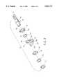
- FIG. 2is an exploded perspective view of the present invention
- FIG. 3is an exploded view of a coupling device according to the present invention.
- FIG. 4is a sectional assembly view of the coupling device shown in FIG. 3;
- FIG. 5is a sectional assembly view of one part of the present invention, showing the coupling devices coupled between the mounting base and the holder base;
- FIG. 6is a top view of FIG. 5;
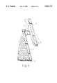
- FIG. 7is a side view of the present invention, showing the tilting angle adjustment of the LCD.
- the LCD support structure shownis used in a computer system, however it can also be used in other fields for monitoring purpose.
- the LCD support structurecomprises a rotary table 2, and an upright support 1 rotatably supported on the rotary table 2.
- the upright support 1 and the rotary table 2form a stand for supporting a LCD 4.
- the upright support 1has a flat bottom 11, and a through hole 111 at the bottom 11.
- the rotary table 2has an upright bolt 21 fastened to the through hole 111 of the upright support 1, permitting the upright support 1 to be turned with the rotary table 2 horizontally through 360°.
- a LCD holder 3is fixedly mounted on the upright support 1 at one side near the top.
- the LCD holder 3comprises a mounting base 31 fixedly secured to the upright support 1, and a holder base 32 fixedly secured to the LCD 4 at the back and coupled to the mounting base 31.
- the mounting base 31 and the holder base 32are respectively fastened to the upright support 1 and the LCD 4 by conventional techniques.
- the mounting base 31comprises a chamber 311 at the side which is not fixed to the upright support 1.
- the holder base 32is pivoted to the mounting base 31 by two coupling devices 5, having an opening 321 adapted for receiving the chamber 311 of the mounting base 31.
- the coupling devices 5are bilaterally connected between the chamber 311 of the mounting base 31 and the holder base 32.
- the coupling device 5comprises a pivot shaft 51 having at least one mounting hole 511 respectively fastened to the holder base 32 by a respective screw 52 (see also FIG. 6), a first partition plate 53 and a second partition plate 54 fixedly mounted around the pivot shaft 51 at one end remote from the at least one mounting hole 511, a corrugated spring plate 55 mounted around the pivot shaft 51 between the partition plates 53;54, a first friction ring plate 56 mounted around the pivot shaft 51 between the corrugated spring plate 55 and the second partition plate 54 and having a projecting strip 561, a second friction ring plate 57 mounted around the pivot shaft 51 between the second partition plate 54 and the first friction ring plate 56 and having a projecting strip 571, a substantially L-shaped mounting plate 58 turned about the pivot shaft 51 between the first friction ring plate 56 and the second friction ring plate 57 and fixedly fastened to the inside of the chamber 311 of the mounting base 31, and a locating plate 59 fixedly mounted around the pivot shaft 51 between the second partition plate
- the mounting plate 58comprises a vertical wall 581 having a pivot hole 582 which receives the pivot shaft 51, a horizontal wall 583 having at least one mounting hole 584 fastened to the chamber 311 of the mounting base 31, a retaining hole 585 disposed at the connecting area between the vertical wall 581 and the horizontal wall 583 and fastened to the projecting strip 561 of the first friction ring plate 56 to stop the friction ring plate 56 from rotary motion relative to the pivot shaft 51, and a projecting stop rod 586 raised from the topmost edge of the vertical wall 581 and adapted to limit the turning angle of the locating plate 59 and the pivot shaft 51.
- the locating plate 59has an arched recess 591 at the top side which receives the projecting stop rod 586 of the mounting plate 58, and a retaining notch 592 at the bottom side forced into engagement with the projecting strip 571 of the second friction ring plate 57.
- the angle of the arched recess 591is made subject to the tilting angle of the LCD 4 desired.
- each coupling device 5when the horizontal wall 583 of the mounting plate 58 of each coupling device 5 is respectively fastened to the mounting base 31 and the pivot shaft 51 of each coupling device 5 is respectively fastened to the holder base 32, the LCD 4 is allowed to be tilted forwards or backwards on the upright support 1.
Landscapes
- Engineering & Computer Science (AREA)
- General Engineering & Computer Science (AREA)
- Mechanical Engineering (AREA)
- Laminated Bodies (AREA)
- Devices For Indicating Variable Information By Combining Individual Elements (AREA)
Abstract
Description
The present invention relates to a LCD (liquid crystal display) support structure for supporting a LCD on a desk, and more particularly to such a LCD support structure which permits the LCD to be tilted forwards or backwards.
Regular monitors commonly occupy much table space because they use a cathode ray tube for producing pictures. Recently, a variety of LCDs (liquid crystal displays) have been well developed, and are intensively used to replace conventional monitors. However, when these LCDs are used and supported on a desk or the like, they cannot be adjusted to the desired tilting angle.
The present invention solves the aforedescribed problem. It is therefore the major object of the present invention to provide a LCD support structure which permits the LCD to be tilted forwards or backwards to the desired angle. According to the preferred embodiment of the present invention, the LCD support structure comprises an upright support supported on a rotary table, and a LCD holder mounted on the stand to hold a LCD, permitting the LCD to be tilted forwards and backwards within a limited angle. The LCD holder comprises a mounting base fixedly fastened to the upright support, a holder base fixedly mounted on the LCD, and two coupling devices bilaterally coupled between the mounting base and the holder base, enabling the holder base to be tilted forwards and backwards within a predetermined angle relative to the mounting base.
FIG. 1 is an elevational view of the present invention;
FIG. 2 is an exploded perspective view of the present invention,
FIG. 3 is an exploded view of a coupling device according to the present invention;
FIG. 4 is a sectional assembly view of the coupling device shown in FIG. 3;
FIG. 5 is a sectional assembly view of one part of the present invention, showing the coupling devices coupled between the mounting base and the holder base;
FIG. 6 is a top view of FIG. 5; and
FIG. 7 is a side view of the present invention, showing the tilting angle adjustment of the LCD.
Referring to FIGS. 1 and 2, the LCD support structure shown is used in a computer system, however it can also be used in other fields for monitoring purpose. As illustrated, the LCD support structure comprises a rotary table 2, and an upright support 1 rotatably supported on the rotary table 2. The upright support 1 and the rotary table 2 form a stand for supporting aLCD 4. The upright support 1 has a flat bottom 11, and a through hole 111 at the bottom 11. The rotary table 2 has anupright bolt 21 fastened to the through hole 111 of the upright support 1, permitting the upright support 1 to be turned with the rotary table 2 horizontally through 360°.
ALCD holder 3 is fixedly mounted on the upright support 1 at one side near the top. TheLCD holder 3 comprises amounting base 31 fixedly secured to the upright support 1, and aholder base 32 fixedly secured to theLCD 4 at the back and coupled to themounting base 31. Themounting base 31 and theholder base 32 are respectively fastened to the upright support 1 and theLCD 4 by conventional techniques. Themounting base 31 comprises achamber 311 at the side which is not fixed to the upright support 1. Theholder base 32 is pivoted to themounting base 31 by two coupling devices 5, having anopening 321 adapted for receiving thechamber 311 of themounting base 31. The coupling devices 5 are bilaterally connected between thechamber 311 of themounting base 31 and theholder base 32.
Referring to FIGS. 3 and 4, the coupling device 5 comprises apivot shaft 51 having at least onemounting hole 511 respectively fastened to theholder base 32 by a respective screw 52 (see also FIG. 6), afirst partition plate 53 and asecond partition plate 54 fixedly mounted around thepivot shaft 51 at one end remote from the at least onemounting hole 511, acorrugated spring plate 55 mounted around thepivot shaft 51 between thepartition plates 53;54, a firstfriction ring plate 56 mounted around thepivot shaft 51 between thecorrugated spring plate 55 and thesecond partition plate 54 and having aprojecting strip 561, a secondfriction ring plate 57 mounted around thepivot shaft 51 between thesecond partition plate 54 and the firstfriction ring plate 56 and having aprojecting strip 571, a substantially L-shaped mounting plate 58 turned about thepivot shaft 51 between the firstfriction ring plate 56 and the secondfriction ring plate 57 and fixedly fastened to the inside of thechamber 311 of themounting base 31, and a locatingplate 59 fixedly mounted around thepivot shaft 51 between thesecond partition plate 54 and the secondfriction ring plate 57. Themounting plate 58 comprises a vertical wall 581 having apivot hole 582 which receives thepivot shaft 51, ahorizontal wall 583 having at least onemounting hole 584 fastened to thechamber 311 of themounting base 31, aretaining hole 585 disposed at the connecting area between the vertical wall 581 and thehorizontal wall 583 and fastened to the projectingstrip 561 of the firstfriction ring plate 56 to stop thefriction ring plate 56 from rotary motion relative to thepivot shaft 51, and a projectingstop rod 586 raised from the topmost edge of the vertical wall 581 and adapted to limit the turning angle of the locatingplate 59 and thepivot shaft 51. The locatingplate 59 has anarched recess 591 at the top side which receives the projectingstop rod 586 of themounting plate 58, and aretaining notch 592 at the bottom side forced into engagement with theprojecting strip 571 of the secondfriction ring plate 57. The angle of thearched recess 591 is made subject to the tilting angle of theLCD 4 desired.
Referring to FIGS. 5 and 6, and FIG. 2 again, when thehorizontal wall 583 of themounting plate 58 of each coupling device 5 is respectively fastened to themounting base 31 and thepivot shaft 51 of each coupling device 5 is respectively fastened to theholder base 32, theLCD 4 is allowed to be tilted forwards or backwards on the upright support 1.
Referring to FIG. 7 and FIGS. from 4 to 6 again, when theLCD 4 is turned with the hand, thepivot shaft 51 of each coupling device 5 is relatively turned in thepivot hole 582 of thecorresponding mounting plate 58, and thearched recess 591 of the locatingplate 59 is moved with thepivot shaft 51 relative to the projectingstop rod 586 of themounting plate 58 to limit the tilting angle of theLCD 4 relative to the upright support 1.
While only one embodiment of the present invention has been shown and described, it will be understood that various modifications and changes could be made thereunto without departing from the spirit and scope of the invention disclosed.
Claims (3)
1. A LCD support structure comprising a stand, and a LCD holder mounted on said stand to hold a LCD (liquid crystal display), permitting said LCD to be tilted forwards and backwards within a limited angle, said LCD holder comprising a mounting base fixedly fastened to said stand, a holder base fixedly mounted on said LCD, and at least one coupling device coupled between said mounting base and said holder base, enabling said holder base to be tilted forwards and backwards within a predetermined angle relative to said mounting base, and wherein said stand comprises an upright support adapted to hold said mounting base of said LCD holder and having a bottom and a through hole at said bottom, and a rotary table having an upright bolt fastened to the through hole of said upright support, permitting said upright support to be turned with said rotary table horizontally through 360°.
2. The LCD support structure of claim 1, wherein each of said at least one coupling devices comprises a pivot shaft having one end fixedly fastened to said holder base, a first partition plate and a second partition plate fixedly mounted around said pivot shaft, a corrugated spring plate mounted around said pivot shaft between said first and second partition plates, a first friction ring plate mounted around said pivot shaft between said corrugated spring plate and said second partition plate, a second friction ring plate mounted around said pivot shaft between said second partition plate and said first friction ring plate, a substantially L-shaped mounting plate, said pivot shaft being rotatably engaged through said mounting plate and the mounting plate being disposed between said first friction ring and said second friction ring plate and fixedly fastened to the mounting base of said LCD holder, and a locating plate fixedly mounted around said pivot shaft between said second partition plate and said second friction ring plate and having an arched recess, said L-shaped mounting plate having a projecting stop rod inserted into the arched recess of said locating plate to limit the turning angle of said locating plate and said pivot shaft relative to said L-shaped mounting plate.
3. The LCD support structure of claim 2 wherein the angle of the arched recess of said locating plate is made subject to the desired angle within which said LCD is to be tilted.
Applications Claiming Priority (2)
| Application Number | Priority Date | Filing Date | Title |
|---|---|---|---|
| TW085217569UTW327460U (en) | 1996-11-16 | 1996-11-16 | Liquid crystal display capable of leaning forward and backward |
| TW85217569 | 1996-11-16 |
Publications (1)
| Publication Number | Publication Date |
|---|---|
| US5854735Atrue US5854735A (en) | 1998-12-29 |
Family
ID=21626169
Family Applications (1)
| Application Number | Title | Priority Date | Filing Date |
|---|---|---|---|
| US08/872,173Expired - Fee RelatedUS5854735A (en) | 1996-11-16 | 1997-06-10 | Device for tiltably supporting a LCD |
Country Status (3)
| Country | Link |
|---|---|
| US (1) | US5854735A (en) |
| DE (1) | DE29710834U1 (en) |
| TW (1) | TW327460U (en) |
Cited By (51)
| Publication number | Priority date | Publication date | Assignee | Title |
|---|---|---|---|---|
| US6024335A (en)* | 1996-11-06 | 2000-02-15 | Samsung Electronics Co., Ltd. | Flat-panel display apparatus |
| US6189850B1 (en)* | 1997-08-09 | 2001-02-20 | Mitac International Corp. | Rotatable LCD screen device |
| US6231021B1 (en)* | 1997-12-12 | 2001-05-15 | Samsung Electronics Co., Ltd. | Flat panel display apparatus equipped with a supplemental stopper |
| US6268997B1 (en) | 1996-11-06 | 2001-07-31 | Samsung Electronics Co., Ltd. | Flat-panel display apparatus having stand unit with cable passing through hinge shaft |
| US6288891B1 (en)* | 1996-11-21 | 2001-09-11 | Canon Kabushiki Kaisha | Movable display apparatus |
| WO2001090848A3 (en)* | 2000-05-22 | 2002-07-18 | Vivek R Huilgol | Rotatable computer display apparatus and method |
| US6437975B1 (en)* | 2000-08-07 | 2002-08-20 | Chuntex Electronic Co., Ltd. | LCD Screen |
| US6445575B1 (en)* | 2000-09-11 | 2002-09-03 | Acer Inc. | Base capable of adjusting the elevation of a panel |
| US20030052857A1 (en)* | 2001-09-14 | 2003-03-20 | Pappas Nicholas J. | Multipurpose computer display system |
| US6603656B2 (en)* | 2001-07-27 | 2003-08-05 | Samsung Electro-Mechanics Co., Ltd. | Stand apparatus in a wireless LAN adapter |
| US20030184193A1 (en)* | 2002-03-26 | 2003-10-02 | Samsung Electronics Co., Ltd. | Monitor having improved swiveling |
| US20040149873A1 (en)* | 2003-02-03 | 2004-08-05 | Murakami Corporation | Display orientation adjustment apparatus |
| KR100443979B1 (en)* | 2001-10-24 | 2004-08-09 | 삼성전자주식회사 | Lcd monitor stand |
| US20040245420A1 (en)* | 2003-01-09 | 2004-12-09 | Decade Industries, Inc. | Adjustable tilt mount |
| US20050029414A1 (en)* | 2003-08-06 | 2005-02-10 | Samsung Electronics Co., Ltd. | Monitor |
| US20050041379A1 (en)* | 2003-08-21 | 2005-02-24 | Samsung Electronics Co., Ltd. | Monitor apparatus |
| US6874744B2 (en) | 2002-02-25 | 2005-04-05 | Wacom Co., Ltd. | Stand for supporting a display in multiple orientations and a display used in combination with said stand |
| US6905101B1 (en) | 2002-06-11 | 2005-06-14 | Chief Manufacturing Inc. | Adjustable, self-balancing flat panel display mounting system |
| US20050125951A1 (en)* | 2003-12-16 | 2005-06-16 | Hao Tai W. | Hinge structure |
| US20050205735A1 (en)* | 2004-02-13 | 2005-09-22 | Fujitsu Limited | Display tilting apparatus |
| US20050207100A1 (en)* | 2004-03-17 | 2005-09-22 | Heckerman Donald A | Flat screen display stand |
| US20050270732A1 (en)* | 2004-06-08 | 2005-12-08 | Titzler David H | All-in-one computer with height adjustable display |
| US7063295B2 (en)* | 2001-06-05 | 2006-06-20 | Lg Electronics Inc. | Apparatus for adjusting an angle of a display means and a connection bracket thereof |
| US20060181637A1 (en)* | 2005-02-16 | 2006-08-17 | Innovative Office Products, Inc. | Quick release assembly for an electronic device |
| US20060284037A1 (en)* | 2005-06-06 | 2006-12-21 | Jay Dittmer | Articulating arm for flat panel display |
| US20080049390A1 (en)* | 2006-08-22 | 2008-02-28 | Funai Electric Co., Ltd. | Display Screen Turning Apparatus |
| US20080099420A1 (en)* | 2006-11-01 | 2008-05-01 | Inventec Multimedia & Telecom Corporation | Rotatable Stand with Adjustable Tightness |
| US20080316689A1 (en)* | 1998-11-20 | 2008-12-25 | Jerry Moscovitch | Computer Display Screen System and Adjustable Screen Mount, and Swinging Screens Therefor |
| US20090154076A1 (en)* | 2006-04-11 | 2009-06-18 | Jin Uk Beak | Image Display Apparatus |
| US20090165252A1 (en)* | 2007-12-31 | 2009-07-02 | Jr-Jiun Chern | Hinge Assembly |
| USD595702S1 (en) | 2008-01-04 | 2009-07-07 | Milestone Av Technologies Llc | Tilt adjustable display interface bracket |
| US20090183440A1 (en)* | 2008-01-22 | 2009-07-23 | Kang Han Cheng | Anti-pinching structure for supportng frame |
| US7641163B2 (en) | 2005-10-21 | 2010-01-05 | Peerless Industries, Inc. | Tilt mounting system |
| USD620943S1 (en) | 2009-01-07 | 2010-08-03 | Milestone Av Technologies Llc | Single arm display mount |
| US7823847B2 (en) | 2008-01-04 | 2010-11-02 | Milestone Av Technologies Llc | Display mount with post-installation adjustment features |
| USD627787S1 (en) | 2009-01-07 | 2010-11-23 | Milestone Av Technologies Llc | Display mount with single articulating arm |
| US7866622B2 (en) | 2007-01-05 | 2011-01-11 | Milestone Av Technologies Llc | In-wall mount |
| US7891622B1 (en) | 2007-02-02 | 2011-02-22 | Peerless Industries, Inc. | Adjustable tilt mounting system |
| USD634328S1 (en) | 2009-01-07 | 2011-03-15 | Milestone Av Technologies Llc | Display mount with dual articulating arms |
| USD642583S1 (en) | 2010-06-28 | 2011-08-02 | Milestone Av Technologies Llc | Swing arm, tilt positionable mount for electronic display |
| US8033902B2 (en)* | 2001-09-28 | 2011-10-11 | Wells William R | Wide screen gaming apparatus |
| US8072739B2 (en) | 2007-01-03 | 2011-12-06 | Milestone Av Technologies Llc | Device mount with selectively positionable tilt axis |
| US8094438B2 (en) | 2007-01-05 | 2012-01-10 | Milestone Av Technologies Llc | Wall-avoiding self-balancing mount for tilt positioning of a flat panel electronic display |
| US8462103B1 (en) | 1998-12-23 | 2013-06-11 | Jerry Moscovitch | Computer display screen system and adjustable screen mount, and swinging screens therefor |
| EP1785660B1 (en)* | 2005-11-14 | 2013-10-02 | LG Electronics Inc. | Stand for a display device |
| US8794579B2 (en) | 2005-06-03 | 2014-08-05 | Steelcase, Inc. | Support arm assembly |
| US8891249B2 (en) | 2009-01-07 | 2014-11-18 | Milestone Av Technologies Llc | Display mount with adjustable position tilt axis |
| CN104154396A (en)* | 2014-07-28 | 2014-11-19 | 成都市晶林科技有限公司 | Camera mounting rack with multi-angle rotating function |
| US8958200B2 (en) | 2008-01-04 | 2015-02-17 | Milestone Av Technologies Llc | Display mount with post-installation adjustment features |
| US9109742B2 (en) | 2008-09-02 | 2015-08-18 | Milestone Av Technologies Llc | Low profile mount for flat panel electronic display |
| US20240272683A1 (en)* | 2018-10-08 | 2024-08-15 | Google Llc | Multipurpose speaker enclosure in a display assistant device |
Citations (4)
| Publication number | Priority date | Publication date | Assignee | Title |
|---|---|---|---|---|
| US5205017A (en)* | 1992-03-18 | 1993-04-27 | Jetta Computers Co., Ltd. | Notebook computer top cover mounting hardware |
| US5537290A (en)* | 1991-07-19 | 1996-07-16 | Teknion Furniture Systems (A Partnership Of Teknion Holdings Inc. And Birchgrove Investments Inc. | Work station with adjustable flat electronic display screen |
| US5702197A (en)* | 1996-07-01 | 1997-12-30 | Chih Ching Industry Ltd. | Structure of pivot joint |
| US5715137A (en)* | 1995-10-19 | 1998-02-03 | Daewoo Electronics Co., Ltd. | Apparatus for providing tilting and rotational movements with pinion gears and rack |
- 1996
- 1996-11-16TWTW085217569Upatent/TW327460U/enunknown
- 1997
- 1997-06-10USUS08/872,173patent/US5854735A/ennot_activeExpired - Fee Related
- 1997-06-20DEDE29710834Upatent/DE29710834U1/ennot_activeExpired - Lifetime
Patent Citations (4)
| Publication number | Priority date | Publication date | Assignee | Title |
|---|---|---|---|---|
| US5537290A (en)* | 1991-07-19 | 1996-07-16 | Teknion Furniture Systems (A Partnership Of Teknion Holdings Inc. And Birchgrove Investments Inc. | Work station with adjustable flat electronic display screen |
| US5205017A (en)* | 1992-03-18 | 1993-04-27 | Jetta Computers Co., Ltd. | Notebook computer top cover mounting hardware |
| US5715137A (en)* | 1995-10-19 | 1998-02-03 | Daewoo Electronics Co., Ltd. | Apparatus for providing tilting and rotational movements with pinion gears and rack |
| US5702197A (en)* | 1996-07-01 | 1997-12-30 | Chih Ching Industry Ltd. | Structure of pivot joint |
Cited By (87)
| Publication number | Priority date | Publication date | Assignee | Title |
|---|---|---|---|---|
| US6024335A (en)* | 1996-11-06 | 2000-02-15 | Samsung Electronics Co., Ltd. | Flat-panel display apparatus |
| US6268997B1 (en) | 1996-11-06 | 2001-07-31 | Samsung Electronics Co., Ltd. | Flat-panel display apparatus having stand unit with cable passing through hinge shaft |
| US6288891B1 (en)* | 1996-11-21 | 2001-09-11 | Canon Kabushiki Kaisha | Movable display apparatus |
| US6189850B1 (en)* | 1997-08-09 | 2001-02-20 | Mitac International Corp. | Rotatable LCD screen device |
| US6231021B1 (en)* | 1997-12-12 | 2001-05-15 | Samsung Electronics Co., Ltd. | Flat panel display apparatus equipped with a supplemental stopper |
| US20080316689A1 (en)* | 1998-11-20 | 2008-12-25 | Jerry Moscovitch | Computer Display Screen System and Adjustable Screen Mount, and Swinging Screens Therefor |
| US20120127646A1 (en)* | 1998-11-20 | 2012-05-24 | Jerry Moscovitch | Computer Display Screen System and Adjustable Screen Mount, and Swinging Screens Therefor |
| US8462103B1 (en) | 1998-12-23 | 2013-06-11 | Jerry Moscovitch | Computer display screen system and adjustable screen mount, and swinging screens therefor |
| WO2001090848A3 (en)* | 2000-05-22 | 2002-07-18 | Vivek R Huilgol | Rotatable computer display apparatus and method |
| US6437975B1 (en)* | 2000-08-07 | 2002-08-20 | Chuntex Electronic Co., Ltd. | LCD Screen |
| US6445575B1 (en)* | 2000-09-11 | 2002-09-03 | Acer Inc. | Base capable of adjusting the elevation of a panel |
| US7063295B2 (en)* | 2001-06-05 | 2006-06-20 | Lg Electronics Inc. | Apparatus for adjusting an angle of a display means and a connection bracket thereof |
| US6603656B2 (en)* | 2001-07-27 | 2003-08-05 | Samsung Electro-Mechanics Co., Ltd. | Stand apparatus in a wireless LAN adapter |
| US20030052857A1 (en)* | 2001-09-14 | 2003-03-20 | Pappas Nicholas J. | Multipurpose computer display system |
| US7129931B2 (en) | 2001-09-14 | 2006-10-31 | Pappas Nicholas J | Multipurpose computer display system |
| US9017157B2 (en) | 2001-09-28 | 2015-04-28 | Igt | Wide screen gaming apparatus |
| US9437071B2 (en) | 2001-09-28 | 2016-09-06 | Igt | Wide screen gaming apparatus |
| US9734657B2 (en) | 2001-09-28 | 2017-08-15 | Igt | Wide screen gaming apparatus |
| US9865123B2 (en) | 2001-09-28 | 2018-01-09 | Igt | Wide screen gaming apparatus |
| US8033902B2 (en)* | 2001-09-28 | 2011-10-11 | Wells William R | Wide screen gaming apparatus |
| KR100443979B1 (en)* | 2001-10-24 | 2004-08-09 | 삼성전자주식회사 | Lcd monitor stand |
| US6874744B2 (en) | 2002-02-25 | 2005-04-05 | Wacom Co., Ltd. | Stand for supporting a display in multiple orientations and a display used in combination with said stand |
| US20030184193A1 (en)* | 2002-03-26 | 2003-10-02 | Samsung Electronics Co., Ltd. | Monitor having improved swiveling |
| US6905101B1 (en) | 2002-06-11 | 2005-06-14 | Chief Manufacturing Inc. | Adjustable, self-balancing flat panel display mounting system |
| US7395996B2 (en) | 2002-06-11 | 2008-07-08 | Csav, Inc. | Adjustable, self-balancing flat panel display mounting system |
| US8490934B2 (en) | 2002-06-11 | 2013-07-23 | Milestone Av Technologies Llc | Adjustable, self-balancing flat panel display mounting system |
| US7954780B2 (en) | 2002-06-11 | 2011-06-07 | Milestone Av Technologies Llc | Adjustable self-balancing flat panel display mounting system |
| US7152836B2 (en) | 2003-01-09 | 2006-12-26 | Csav, Inc. | Adjustable tilt mount |
| US8235342B2 (en) | 2003-01-09 | 2012-08-07 | Milestone AV Techonologies LLC | Adjustable tilt mount |
| US7178775B2 (en) | 2003-01-09 | 2007-02-20 | Csav, Inc. | Adjustable tilt mount |
| US20040245420A1 (en)* | 2003-01-09 | 2004-12-09 | Decade Industries, Inc. | Adjustable tilt mount |
| US7438269B2 (en) | 2003-01-09 | 2008-10-21 | Csav, Inc. | Adjustable tilt mount |
| US6966532B2 (en)* | 2003-02-03 | 2005-11-22 | Murakami Corporation | Display orientation adjustment apparatus |
| US20040149873A1 (en)* | 2003-02-03 | 2004-08-05 | Murakami Corporation | Display orientation adjustment apparatus |
| US7424994B2 (en) | 2003-08-06 | 2008-09-16 | Samsung Electronics Co., Ltd. | Monitor and a monitor supporting apparatus |
| US20050029414A1 (en)* | 2003-08-06 | 2005-02-10 | Samsung Electronics Co., Ltd. | Monitor |
| EP1505333A3 (en)* | 2003-08-06 | 2005-06-29 | Samsung Electronics Co., Ltd. | Monitor |
| US7336478B2 (en)* | 2003-08-21 | 2008-02-26 | Samsung Electronics Co., Ltd. | Monitor apparatus |
| US20050041379A1 (en)* | 2003-08-21 | 2005-02-24 | Samsung Electronics Co., Ltd. | Monitor apparatus |
| US20050125951A1 (en)* | 2003-12-16 | 2005-06-16 | Hao Tai W. | Hinge structure |
| US6920670B2 (en)* | 2003-12-16 | 2005-07-26 | Tai Wen Hao | Hinge structure |
| US7147191B2 (en)* | 2004-02-13 | 2006-12-12 | Fujitsu Limited | Display tilting apparatus |
| US20050205735A1 (en)* | 2004-02-13 | 2005-09-22 | Fujitsu Limited | Display tilting apparatus |
| US7251125B2 (en) | 2004-03-17 | 2007-07-31 | Heckerman Donald A | Flat screen display stand |
| US20050207100A1 (en)* | 2004-03-17 | 2005-09-22 | Heckerman Donald A | Flat screen display stand |
| US7180731B2 (en) | 2004-06-08 | 2007-02-20 | Flextronics International Usa, Inc. | All-in-one computer with height adjustable display |
| US20050270732A1 (en)* | 2004-06-08 | 2005-12-08 | Titzler David H | All-in-one computer with height adjustable display |
| US20100214730A1 (en)* | 2004-06-08 | 2010-08-26 | Titzler David H | All-in-one computer with height adjustable display |
| US8373976B2 (en) | 2004-06-08 | 2013-02-12 | Flextronics International Usa, Inc. | All-in-one computer with height adjustable display |
| US7673838B2 (en) | 2005-02-16 | 2010-03-09 | Innovative Office Products, Inc. | Quick release assembly for an electronic device |
| US20060181637A1 (en)* | 2005-02-16 | 2006-08-17 | Innovative Office Products, Inc. | Quick release assembly for an electronic device |
| US8794579B2 (en) | 2005-06-03 | 2014-08-05 | Steelcase, Inc. | Support arm assembly |
| US7793903B2 (en) | 2005-06-06 | 2010-09-14 | Milestone Av Technologies Llc | Articulating arm for flat panel display |
| US20060284037A1 (en)* | 2005-06-06 | 2006-12-21 | Jay Dittmer | Articulating arm for flat panel display |
| US8313073B2 (en) | 2005-10-21 | 2012-11-20 | Peerless Industries, Inc. | Tilt mounting system |
| US8157233B2 (en) | 2005-10-21 | 2012-04-17 | Peerless Industries, Inc. | Tilt mounting system |
| US8684326B2 (en) | 2005-10-21 | 2014-04-01 | Peerless Industries, Inc. | Tilt mounting system |
| US7753332B2 (en) | 2005-10-21 | 2010-07-13 | Peerless Industries, Inc. | Tilt mounting system |
| US7641163B2 (en) | 2005-10-21 | 2010-01-05 | Peerless Industries, Inc. | Tilt mounting system |
| EP1785660B1 (en)* | 2005-11-14 | 2013-10-02 | LG Electronics Inc. | Stand for a display device |
| US20090154076A1 (en)* | 2006-04-11 | 2009-06-18 | Jin Uk Beak | Image Display Apparatus |
| US8142064B2 (en)* | 2006-04-11 | 2012-03-27 | Lg Electronics Inc. | Image display apparatus |
| US20080049390A1 (en)* | 2006-08-22 | 2008-02-28 | Funai Electric Co., Ltd. | Display Screen Turning Apparatus |
| US7869203B2 (en)* | 2006-08-22 | 2011-01-11 | Funai Electric Co., Ltd. | Display screen turning apparatus |
| US20080099420A1 (en)* | 2006-11-01 | 2008-05-01 | Inventec Multimedia & Telecom Corporation | Rotatable Stand with Adjustable Tightness |
| US8072739B2 (en) | 2007-01-03 | 2011-12-06 | Milestone Av Technologies Llc | Device mount with selectively positionable tilt axis |
| US8508918B2 (en) | 2007-01-05 | 2013-08-13 | Milestone Av Technologies Llc | Wall-avoiding self-balancing mount for tilt positioning of a flat panel electronic display |
| US7866622B2 (en) | 2007-01-05 | 2011-01-11 | Milestone Av Technologies Llc | In-wall mount |
| US8094438B2 (en) | 2007-01-05 | 2012-01-10 | Milestone Av Technologies Llc | Wall-avoiding self-balancing mount for tilt positioning of a flat panel electronic display |
| US7891622B1 (en) | 2007-02-02 | 2011-02-22 | Peerless Industries, Inc. | Adjustable tilt mounting system |
| US20090165252A1 (en)* | 2007-12-31 | 2009-07-02 | Jr-Jiun Chern | Hinge Assembly |
| US8958200B2 (en) | 2008-01-04 | 2015-02-17 | Milestone Av Technologies Llc | Display mount with post-installation adjustment features |
| USD595702S1 (en) | 2008-01-04 | 2009-07-07 | Milestone Av Technologies Llc | Tilt adjustable display interface bracket |
| US7823847B2 (en) | 2008-01-04 | 2010-11-02 | Milestone Av Technologies Llc | Display mount with post-installation adjustment features |
| US8046874B2 (en)* | 2008-01-22 | 2011-11-01 | Jarllytec Co., Ltd. | Anti-pinching structure for supporting frame |
| US8307506B2 (en)* | 2008-01-22 | 2012-11-13 | Jarllytec Co., Ltd. | Anti-pinching structure for supporting frame |
| US20110192954A1 (en)* | 2008-01-22 | 2011-08-11 | Jarllytec Co., Ltd. | Anti-pinching structure for supporting frame |
| US20090183440A1 (en)* | 2008-01-22 | 2009-07-23 | Kang Han Cheng | Anti-pinching structure for supportng frame |
| US9109742B2 (en) | 2008-09-02 | 2015-08-18 | Milestone Av Technologies Llc | Low profile mount for flat panel electronic display |
| USD620943S1 (en) | 2009-01-07 | 2010-08-03 | Milestone Av Technologies Llc | Single arm display mount |
| US8891249B2 (en) | 2009-01-07 | 2014-11-18 | Milestone Av Technologies Llc | Display mount with adjustable position tilt axis |
| USD627787S1 (en) | 2009-01-07 | 2010-11-23 | Milestone Av Technologies Llc | Display mount with single articulating arm |
| USD634328S1 (en) | 2009-01-07 | 2011-03-15 | Milestone Av Technologies Llc | Display mount with dual articulating arms |
| USD642583S1 (en) | 2010-06-28 | 2011-08-02 | Milestone Av Technologies Llc | Swing arm, tilt positionable mount for electronic display |
| CN104154396A (en)* | 2014-07-28 | 2014-11-19 | 成都市晶林科技有限公司 | Camera mounting rack with multi-angle rotating function |
| US20240272683A1 (en)* | 2018-10-08 | 2024-08-15 | Google Llc | Multipurpose speaker enclosure in a display assistant device |
| US12405635B2 (en)* | 2018-10-08 | 2025-09-02 | Google Llc | Multipurpose speaker enclosure in a display assistant device |
Also Published As
| Publication number | Publication date |
|---|---|
| TW327460U (en) | 1998-02-21 |
| DE29710834U1 (en) | 1997-09-04 |
Similar Documents
| Publication | Publication Date | Title |
|---|---|---|
| US5854735A (en) | Device for tiltably supporting a LCD | |
| US7287729B2 (en) | Display apparatus | |
| US5941493A (en) | LCD support system | |
| US6510049B2 (en) | Adjustable display monitor unit | |
| US6061104A (en) | Flat panel display and stand with vertical adjustment and tilt adjustment | |
| US4575033A (en) | Tilt-swivel base for a CRT display terminal | |
| EP1785661B1 (en) | Apparatus to support a display device | |
| US6822857B2 (en) | Monitor improved in a tilting structure | |
| US6651943B2 (en) | LCD monitor stand | |
| US20050258319A1 (en) | Monitor apparatus | |
| US20110121151A1 (en) | Display mount | |
| US8608119B2 (en) | Display stand | |
| US7320454B2 (en) | Display supporting apparatus | |
| US7267312B2 (en) | Display apparatus | |
| US11788671B2 (en) | Supporting device | |
| US20090179126A1 (en) | Stand for flat-panel display | |
| CA2391160A1 (en) | Horizontal three screen lcd display system | |
| EP0461661A2 (en) | Tiltable turntable for display monitor | |
| JP3135891B2 (en) | Lcd display arm stand | |
| JPH11338576A (en) | Liquid crystal display support device | |
| KR200231316Y1 (en) | Stand for LCD monitor | |
| CN219263609U (en) | Adjustable liquid crystal display fixing seat | |
| KR200265449Y1 (en) | dual LCD monitor supporter | |
| KR20000000827U (en) | LCD monitor | |
| KR200168705Y1 (en) | Simple lcd display stand |
Legal Events
| Date | Code | Title | Description |
|---|---|---|---|
| AS | Assignment | Owner name:ADI CORPORATION, TAIWAN Free format text:ASSIGNMENT OF ASSIGNORS INTEREST;ASSIGNOR:CHENG, YUNG-LONG;REEL/FRAME:008606/0054 Effective date:19970530 | |
| REMI | Maintenance fee reminder mailed | ||
| LAPS | Lapse for failure to pay maintenance fees | ||
| STCH | Information on status: patent discontinuation | Free format text:PATENT EXPIRED DUE TO NONPAYMENT OF MAINTENANCE FEES UNDER 37 CFR 1.362 | |
| FP | Lapsed due to failure to pay maintenance fee | Effective date:20021229 |