US5854697A - Waveguide hologram illuminators - Google Patents
Waveguide hologram illuminatorsDownload PDFInfo
- Publication number
- US5854697A US5854697AUS08/473,966US47396695AUS5854697AUS 5854697 AUS5854697 AUS 5854697AUS 47396695 AUS47396695 AUS 47396695AUS 5854697 AUS5854697 AUS 5854697A
- Authority
- US
- United States
- Prior art keywords
- light
- hologram
- holographic
- illumination system
- thin substrate
- Prior art date
- Legal status (The legal status is an assumption and is not a legal conclusion. Google has not performed a legal analysis and makes no representation as to the accuracy of the status listed.)
- Expired - Fee Related
Links
- 238000005286illuminationMethods0.000claimsabstractdescription42
- 239000000758substrateSubstances0.000claimsabstractdescription16
- 238000009826distributionMethods0.000claimsdescription6
- 230000010287polarizationEffects0.000claimsdescription5
- 230000008878couplingEffects0.000claimsdescription3
- 238000010168coupling processMethods0.000claimsdescription3
- 238000005859coupling reactionMethods0.000claimsdescription3
- 238000009877renderingMethods0.000abstract1
- 230000003287optical effectEffects0.000description7
- 230000001427coherent effectEffects0.000description5
- 238000013459approachMethods0.000description4
- 230000003595spectral effectEffects0.000description4
- 238000002474experimental methodMethods0.000description3
- 239000011521glassSubstances0.000description3
- 238000000034methodMethods0.000description3
- 230000008901benefitEffects0.000description2
- 239000013256coordination polymerSubstances0.000description2
- 238000012937correctionMethods0.000description2
- 239000000839emulsionSubstances0.000description2
- 230000028161membrane depolarizationEffects0.000description2
- 230000008569processEffects0.000description2
- 230000002123temporal effectEffects0.000description2
- 239000004568cementSubstances0.000description1
- 239000003086colorantSubstances0.000description1
- 238000004891communicationMethods0.000description1
- 238000013461designMethods0.000description1
- 230000001066destructive effectEffects0.000description1
- 238000010586diagramMethods0.000description1
- 239000006185dispersionSubstances0.000description1
- 239000000835fiberSubstances0.000description1
- 238000001914filtrationMethods0.000description1
- 238000003384imaging methodMethods0.000description1
- 238000011835investigationMethods0.000description1
- 230000007246mechanismEffects0.000description1
- 239000013307optical fiberSubstances0.000description1
- 239000003973paintSubstances0.000description1
- 230000001902propagating effectEffects0.000description1
- 230000003252repetitive effectEffects0.000description1
- 230000035945sensitivityEffects0.000description1
- 229910052709silverInorganic materials0.000description1
- 239000004332silverSubstances0.000description1
- -1silver halideChemical class0.000description1
- 239000010409thin filmSubstances0.000description1
- 230000009466transformationEffects0.000description1
Images

Classifications
- G—PHYSICS
- G02—OPTICS
- G02B—OPTICAL ELEMENTS, SYSTEMS OR APPARATUS
- G02B6/00—Light guides; Structural details of arrangements comprising light guides and other optical elements, e.g. couplings
- G02B6/0001—Light guides; Structural details of arrangements comprising light guides and other optical elements, e.g. couplings specially adapted for lighting devices or systems
- G02B6/0011—Light guides; Structural details of arrangements comprising light guides and other optical elements, e.g. couplings specially adapted for lighting devices or systems the light guides being planar or of plate-like form
- G02B6/0033—Means for improving the coupling-out of light from the light guide
- G02B6/005—Means for improving the coupling-out of light from the light guide provided by one optical element, or plurality thereof, placed on the light output side of the light guide
- G—PHYSICS
- G03—PHOTOGRAPHY; CINEMATOGRAPHY; ANALOGOUS TECHNIQUES USING WAVES OTHER THAN OPTICAL WAVES; ELECTROGRAPHY; HOLOGRAPHY
- G03H—HOLOGRAPHIC PROCESSES OR APPARATUS
- G03H1/00—Holographic processes or apparatus using light, infrared or ultraviolet waves for obtaining holograms or for obtaining an image from them; Details peculiar thereto
- G03H1/04—Processes or apparatus for producing holograms
- G03H1/0402—Recording geometries or arrangements
- G03H1/0408—Total internal reflection [TIR] holograms, e.g. edge lit or substrate mode holograms
- G—PHYSICS
- G03—PHOTOGRAPHY; CINEMATOGRAPHY; ANALOGOUS TECHNIQUES USING WAVES OTHER THAN OPTICAL WAVES; ELECTROGRAPHY; HOLOGRAPHY
- G03H—HOLOGRAPHIC PROCESSES OR APPARATUS
- G03H1/00—Holographic processes or apparatus using light, infrared or ultraviolet waves for obtaining holograms or for obtaining an image from them; Details peculiar thereto
- G03H1/22—Processes or apparatus for obtaining an optical image from holograms
- G03H1/2286—Particular reconstruction light ; Beam properties
- G—PHYSICS
- G02—OPTICS
- G02B—OPTICAL ELEMENTS, SYSTEMS OR APPARATUS
- G02B6/00—Light guides; Structural details of arrangements comprising light guides and other optical elements, e.g. couplings
- G02B6/0001—Light guides; Structural details of arrangements comprising light guides and other optical elements, e.g. couplings specially adapted for lighting devices or systems
- G02B6/0011—Light guides; Structural details of arrangements comprising light guides and other optical elements, e.g. couplings specially adapted for lighting devices or systems the light guides being planar or of plate-like form
- G02B6/0013—Means for improving the coupling-in of light from the light source into the light guide
- G02B6/0023—Means for improving the coupling-in of light from the light source into the light guide provided by one optical element, or plurality thereof, placed between the light guide and the light source, or around the light source
- G02B6/003—Lens or lenticular sheet or layer
- G—PHYSICS
- G02—OPTICS
- G02B—OPTICAL ELEMENTS, SYSTEMS OR APPARATUS
- G02B6/00—Light guides; Structural details of arrangements comprising light guides and other optical elements, e.g. couplings
- G02B6/0001—Light guides; Structural details of arrangements comprising light guides and other optical elements, e.g. couplings specially adapted for lighting devices or systems
- G02B6/0011—Light guides; Structural details of arrangements comprising light guides and other optical elements, e.g. couplings specially adapted for lighting devices or systems the light guides being planar or of plate-like form
- G02B6/0065—Manufacturing aspects; Material aspects
- G—PHYSICS
- G02—OPTICS
- G02B—OPTICAL ELEMENTS, SYSTEMS OR APPARATUS
- G02B6/00—Light guides; Structural details of arrangements comprising light guides and other optical elements, e.g. couplings
- G02B6/24—Coupling light guides
- G02B6/26—Optical coupling means
- G02B6/28—Optical coupling means having data bus means, i.e. plural waveguides interconnected and providing an inherently bidirectional system by mixing and splitting signals
- G02B6/2804—Optical coupling means having data bus means, i.e. plural waveguides interconnected and providing an inherently bidirectional system by mixing and splitting signals forming multipart couplers without wavelength selective elements, e.g. "T" couplers, star couplers
- G02B6/2848—Optical coupling means having data bus means, i.e. plural waveguides interconnected and providing an inherently bidirectional system by mixing and splitting signals forming multipart couplers without wavelength selective elements, e.g. "T" couplers, star couplers having refractive means, e.g. imaging elements between light guides as splitting, branching and/or combining devices, e.g. lenses, holograms
- G—PHYSICS
- G02—OPTICS
- G02B—OPTICAL ELEMENTS, SYSTEMS OR APPARATUS
- G02B6/00—Light guides; Structural details of arrangements comprising light guides and other optical elements, e.g. couplings
- G02B6/24—Coupling light guides
- G02B6/42—Coupling light guides with opto-electronic elements
- G02B6/43—Arrangements comprising a plurality of opto-electronic elements and associated optical interconnections
- G—PHYSICS
- G03—PHOTOGRAPHY; CINEMATOGRAPHY; ANALOGOUS TECHNIQUES USING WAVES OTHER THAN OPTICAL WAVES; ELECTROGRAPHY; HOLOGRAPHY
- G03H—HOLOGRAPHIC PROCESSES OR APPARATUS
- G03H1/00—Holographic processes or apparatus using light, infrared or ultraviolet waves for obtaining holograms or for obtaining an image from them; Details peculiar thereto
- G03H1/22—Processes or apparatus for obtaining an optical image from holograms
- G03H1/2294—Addressing the hologram to an active spatial light modulator
- G—PHYSICS
- G03—PHOTOGRAPHY; CINEMATOGRAPHY; ANALOGOUS TECHNIQUES USING WAVES OTHER THAN OPTICAL WAVES; ELECTROGRAPHY; HOLOGRAPHY
- G03H—HOLOGRAPHIC PROCESSES OR APPARATUS
- G03H1/00—Holographic processes or apparatus using light, infrared or ultraviolet waves for obtaining holograms or for obtaining an image from them; Details peculiar thereto
- G03H1/22—Processes or apparatus for obtaining an optical image from holograms
- G03H1/2202—Reconstruction geometries or arrangements
- G03H2001/2223—Particular relationship between light source, hologram and observer
- G03H2001/2226—Edge lit holograms
Definitions
- This inventionpertains to the use of waveguide holograms for use as illuminators of objects having specific illumination requirements.
- objects having special illumination requirementssuch as display holograms or spatial light modulators can be illuminated with waveguide holograms as disclosed herein.
- waveguide hologramsare disclosed, based on the use of thin substrate waveguides. These waveguides are characterized the relationship between the width w of an incident laser beam coupled onto an optical waveguide having a thickness t. This relationship is controlled by ⁇ , where ⁇ is the wavelength of the incident lightwave. Thin substrate waveguides are characterized by t>> ⁇ . In this situation, one can avoid difficulties encountered in coupling the optical source to the thin film waveguide, and allow for convenient white light illumination. At the same time, t ⁇ w, so that the illumination obtained uniform.
- the illuminatorseeks to pattern the light so it hits only in preselected areas. This can increase illuminator efficiency if the light is redirected, instead of simply being partially blocked.
- spectral filteringmay be required.
- illumination of hologramspresents particular problems. Some may have their own built-in spectral filters, while others permit white light illumination. If incoherent light sources used, the filter provides the needed amount of spatial coherence, while if lasers are employed, the filter is required to clean up the coherent noise. Accordingly, it remains an object of those of skill in the art to provide a method for selectively illuminating demanding objects, such as holograms and spatial light modulators.
- the illumination systemcan comprise a thin substrate waveguide optically coupled to a coherent light source, such as a laser. This illumination system provides extremely high diffraction efficiencies.
- Non-uniformity of the diffracted wavefront in the direction of propagationcan be compensated for by exposing a photographic emulsion to the beam without compensation.
- the photographic negativeabsorbs most where the beam is brightest, and therefore, upon subsequent illumination through the negative, the wavefront passing is uniform.
- the hologram of the waveguide hologram illuminatorcan be recorded non-uniformly, so that the reconstructed beam formed is uniform in intensity. Both corrections can be employed.
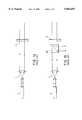
- FIG. 1a and 1bare illustrations of prior art illumination systems for transmissive and reflective objects respectively.
- FIG. 2(a)(b)is an illustration of a thin substrate waveguide optically coupled to a light source.
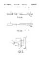
- FIG. 3is an illustration of the volume occupied by conventional lens systems.
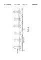
- FIG. 4is an illustration of repetitive diffraction of light out of a waveguide in the direction of propagation.
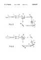
- FIGS. 5 and 6are schematic representations of recording systems used to record a waveguide hologram grating to prepare the illuminator of the claimed invention.
- FIG. 7is a schematic representation of an illumination system according to the invention wherein a light source is directed through a diffraction means into the waveguide hologram and out through a hologram to illuminate a spatial light modulator.
- the illumination system claimed hereinis based on the waveguide hologram of the parent application incorporated herein.
- the illumination systemcomprises a light source which is optically coupled to a waveguide, on a surface of which is formed a hologram, which can be displayed or used to illuminate, selectively, the object of interest.
- waveguide hologramsare referred to as WGH.
- WGHsare normally flat and can be optically contacted to the objects they illuminate as indicated by the diagrams of FIG. 2.
- the relatively complicated systems of FIG. 1are replaced by compact, rugged arrangements. Mutual alignment is easily maintained and reflection losses at the air-glass interfaces are readily reduced by index matching oil or optical cement.
- the WGH illuminatoroccupies much less space.
- a conventional lens illumination systemoccupies a volume approximately ##EQU1## wherein f is the focal length of the main lens, A is the numerical aperture, and M is the magnification of the collimator.
- the volume for the illuminatorsincreases to ##EQU2##
- the active volume for a WGH illuminatoris no more than ##EQU3## where is the thickness of the waveguide substrate. Usually h ⁇ f. Taking the ratio of V, to V wi , we obtain the gain of a WGH illuminator as ##EQU4##
- FIG. 4This aspect of the WGH illumination process is shown in FIG. 4. Assume the guided illumination beam is collimated. When it reaches the area where a hologram is placed, the beam encounters the region 1 of the hologram first. Part of light is diffracted as the reconstruction of the image, and the rest of light reflected. After the total internal reflection at the other waveguide surface, the residual light illuminates the region 2 on the hologram and undergoes the second reconstruction. This process repeats until the illumination beam passes the hologram area.
- a WGHtends to produce two diffracted beams, one out of each side.
- thiscan be an advantage.
- it is not easy to use both beams and the unutilized beamreduces the useful efficiency and may introduce noise into the system.
- FIG. 7Such a system is illustrated in FIG. 7, wherein a light source S impinges on the waveguide hologram WGH through an input grating or diffraction means D. Light is emitted through the hologram H, illuminating a spatial light modulator SLM.
- Aligning sensitivitycan be combatted in two ways. First, we can attached the source, such as a diode laser, firmly to the edge of the waveguide or to the input of an input coupler or to an optical fiber which is itself firmly attached to the optical input couplers. Second, we can use a spatially and spectrally broad source and allow the waveguide to select out the portion of the available light which is properly matched to it. A WGH can achieve high spectral selectivity about 2-5A due to its double selection by the hologram and the waveguide.
- the sourcesuch as a diode laser
- Compensating for illumination depletioncan be done a priori or a posteriori.
- a posteriori compensationis very light inefficient. Basically, we may expose a photographic emulsion to the uncompensated beam. A photographic negative of that pattern absorbs most where the beam is brightest and, therefore, uniformizes the wavefront passing through it. The a priori approach records the hologram nonuniformly so that the reconstructed beam is uniform. To derive an appropriate nonuniform beam to record, we illuminate uniformly through the photographic negative just described. For extremely high uniformity, we might follow a priori compensation with a posteriori compensation which can now be highly efficient because it is making only small corrections.
- the first configurationis a modified conventional holographic recording system (FIG. 5).
- a cubic glass prism, CPis employed to create a reference beam with very steep incidence angle.
- the recording plate, Ris optically contacted with CP by index matching.
- the second configuration(FIG. 6) is suitable for the waveguides with more stringent requirements.
- the reference beamis coupled into the waveguide by a prism coupler, PC, and can be exactly reproduced for reconstruction. All holograms discussed in this communication were recorded on silver halide plates (Agf a 8E75) and bleached.
- the recording mediumwas optically contacted to a thin substrate glass waveguide with index matching oil.
- a SLMwas illuminated by a white light illuminator which was recorded using the system of FIG. 5.
- a plastic fiber ribbonwas used to couple the light from a remote source indicating the convenience and flexibility of such illuminators.
- the color of the diffracted illuminating lightdepends, in this configuration, on the viewing angle. However, if a diffuser is placed between the SLM and the WGH, the colors are angularly mixed to reproduce the white illumination of the source at all angles.
- Illuminating the hologram by coherent laser lightgenerated a coherent illumination beam suitable for reconstructing a 3-D holographic image.
- the quality of the reconstructed beamswas analyzed from various points of view qualitatively and also quantitatively. Particular emphasis was placed on polarization and phase characteristics. A slight nonuniform depolarization was observed by using an imaging polarimeter. The origin of this depolarization and its nonuniformity is probably in some local strains and is still under investigation.
Landscapes
- Physics & Mathematics (AREA)
- General Physics & Mathematics (AREA)
- Optics & Photonics (AREA)
- Holo Graphy (AREA)
Abstract
Description
This is a Continuation of application Ser. No. 07/902,881 filed on Jun. 23, 1992, now U.S. Pat. No. 5,515,184 which is a continuation-in-part of U.S. patent application Ser. No. 07/790,516 filed Nov. 12, 1991, now abandoned. The entire disclosure of the parent application is incorporated herein by reference.
This invention pertains to the use of waveguide holograms for use as illuminators of objects having specific illumination requirements. In particular, objects having special illumination requirements, such as display holograms or spatial light modulators can be illuminated with waveguide holograms as disclosed herein.
In applicants' parent application Ser. No. 07/790,516, waveguide holograms are disclosed, based on the use of thin substrate waveguides. These waveguides are characterized the relationship between the width w of an incident laser beam coupled onto an optical waveguide having a thickness t. This relationship is controlled by λ, where λ is the wavelength of the incident lightwave. Thin substrate waveguides are characterized by t>>λ. In this situation, one can avoid difficulties encountered in coupling the optical source to the thin film waveguide, and allow for convenient white light illumination. At the same time, t<w, so that the illumination obtained uniform.
The inventors have now discovered that these thin substrate waveguides can be particularly used for situations requiring controlled illumination. There are a wide variety of situations which require illumination of an object in an controlled fashion. This is particularly the case where one seeks to illuminate a spatial light modulator (SLM) or hologram. Certain requirements present major difficulties for conventional illumination systems. Initially, illustrating with traditional illumination of a transmissive object (FIG. 1a) and a reflective object (FIG. 1b), conventional illuminators require a substantial amount of space to perform the transformation from the wavefront emitted by the light source to the one required on the object. This space usually contains several optical elements which are the origin for stability problems, alignment difficulties and obstruction of other light beams that may be required in the optical system. Second, for some illumination, it is desired not to flood the object to be illuminated with light. Rather, the illuminator seeks to pattern the light so it hits only in preselected areas. This can increase illuminator efficiency if the light is redirected, instead of simply being partially blocked. Additionally, if the light source is broad band, spectral filtering may be required. As one example of such a situation, illumination of holograms presents particular problems. Some may have their own built-in spectral filters, while others permit white light illumination. If incoherent light sources used, the filter provides the needed amount of spatial coherence, while if lasers are employed, the filter is required to clean up the coherent noise. Accordingly, it remains an object of those of skill in the art to provide a method for selectively illuminating demanding objects, such as holograms and spatial light modulators.
Applicants have discovered that thin substrate waveguides can be used to provide improved, controlled illumination of objects, including holograms and spatial light modulators. The illumination system can comprise a thin substrate waveguide optically coupled to a coherent light source, such as a laser. This illumination system provides extremely high diffraction efficiencies.
Non-uniformity of the diffracted wavefront in the direction of propagation can be compensated for by exposing a photographic emulsion to the beam without compensation. The photographic negative absorbs most where the beam is brightest, and therefore, upon subsequent illumination through the negative, the wavefront passing is uniform. In an alternative approach, the hologram of the waveguide hologram illuminator can be recorded non-uniformly, so that the reconstructed beam formed is uniform in intensity. Both corrections can be employed.
FIG. 1a and 1b are illustrations of prior art illumination systems for transmissive and reflective objects respectively.
FIG. 2(a)(b) is an illustration of a thin substrate waveguide optically coupled to a light source.
FIG. 3 is an illustration of the volume occupied by conventional lens systems.
FIG. 4 is an illustration of repetitive diffraction of light out of a waveguide in the direction of propagation.
FIGS. 5 and 6 are schematic representations of recording systems used to record a waveguide hologram grating to prepare the illuminator of the claimed invention.
FIG. 7 is a schematic representation of an illumination system according to the invention wherein a light source is directed through a diffraction means into the waveguide hologram and out through a hologram to illuminate a spatial light modulator.
This invention may be better understood by the following discussions, with reference to the Figures presented. The illumination system claimed herein is based on the waveguide hologram of the parent application incorporated herein. Thus, in essence, the illumination system comprises a light source which is optically coupled to a waveguide, on a surface of which is formed a hologram, which can be displayed or used to illuminate, selectively, the object of interest. Herein, waveguide holograms are referred to as WGH.
WGHs are normally flat and can be optically contacted to the objects they illuminate as indicated by the diagrams of FIG. 2. Thus the relatively complicated systems of FIG. 1 are replaced by compact, rugged arrangements. Mutual alignment is easily maintained and reflection losses at the air-glass interfaces are readily reduced by index matching oil or optical cement.
Comparing with a conventional lens illumination system, the WGH illuminator occupies much less space. Shown in FIG. 3, a conventional lens illumination system occupies a volume approximately ##EQU1## wherein f is the focal length of the main lens, A is the numerical aperture, and M is the magnification of the collimator. For reflective spatial light modulators or SLMs, the volume for the illuminators increases to ##EQU2## On the other hand, the active volume for a WGH illuminator is no more than ##EQU3## where is the thickness of the waveguide substrate. Usually h<<f. Taking the ratio of V, to Vwi, we obtain the gain of a WGH illuminator as ##EQU4##
The diffraction efficiency, n, is the fraction of the light from the illuminating source which is diffracted into the required beam. For conventional display holograms, n=0.6 is sometimes obtained and for holograms made by two plane waves n=0.99 is attainable. WGH illuminators can, in principle, also achieve very high diffraction efficiency (of order approaching 0.99), however, high efficiencies over large area holograms requires very careful design as will be discussed below.
For purposes (minimizing noise, making viewers comfortable, etc.) what is more important than just the efficiency is the absence of stray light propagating forward the observer. From this point of view WGHs are ideal. The undiffracted light from a WGH illuminator never enters the instrumentation or the eye of the viewer due to the total internal reflection at the waveguide surfaces. Let the diffracted light have irradiance Hd and the undiffracted light leaving the hologram be Hu. Then ##EQU5## for display holograms can approach 0.25. For holographic recording of two plane waves, E an approach 0.99, while for all types of WGH E≧0.999 is routinely achievable since the undiffracted light is trapped in the waveguide.
Along with the advantages of WGHs as illuminators, there are some penalties that must be paid. With a laser illuminated single-mode waveguide hologram, alignment of the laser beam is critical. This can lead to certain lack of ruggedness. Because light enters one side of the waveguide hologram and travels to the other, there is a time delay across the hologram. If we try to use a waveguide hologram for clock distribution, this builds in a clock skew. If we use the waveguide hologram as a way to produce spatially-coherent illumination beam, we must be sure that the temporal coherence time of the source exceeds this time delay. Another way of saying this is that source temporal coherence manifests itself as spatial coherence in a waveguide hologram illuminator.
In addition, nonuniformity of the diffracted wavefront along the propagation direction is inevitable unless combated. Light diffracted out of the waveguide at one point is simply not available for diffraction at a later point. This aspect of the WGH illumination process is shown in FIG. 4. Assume the guided illumination beam is collimated. When it reaches the area where a hologram is placed, the beam encounters theregion 1 of the hologram first. Part of light is diffracted as the reconstruction of the image, and the rest of light reflected. After the total internal reflection at the other waveguide surface, the residual light illuminates theregion 2 on the hologram and undergoes the second reconstruction. This process repeats until the illumination beam passes the hologram area. Because WGHs have this unusual reconstructive mechanism, it is necessary to distinguish two different types of diffraction efficiencies. Assume the initial intensity of the illumination beam in FIG. 4 is Io, and the intensities of diffracted light fromregion
If the hologram is recorded uniformly, that is nL1 =nL2 = . . . =NLi = . . . =nLN =N, then
I.sub.i =I.sub.o η(I-.sub.η).sup.i-1
Substitute Eq. 8 to Eq. 6, the global efficiency is expressed as:
η.sub.G l-(l-η).sup.N.
by plotting I, vs. i as shown in FIG. 4, we see that the holographic image is not reconstructed uniformly if all the local efficiencies are the same, i.e., the hologram is recorded uniformly. This problem may be called illumination depletion.
Moreover, a WGH tends to produce two diffracted beams, one out of each side. For display holograms, this can be an advantage. However, for illuminator holograms, it is not easy to use both beams and the unutilized beam reduces the useful efficiency and may introduce noise into the system.
Additionally, if light enters the waveguide by diffraction at some angle to the waveguide and exits via the hologram at any angle other than the angle or its opposite, light dispersion results. Thus, an input of white light results in a spectral output. This can be redressed by providing an input grating or hologram diffractor with an output direction equal or opposite to the angle of the hologram output. Both diffraction events are dispersive, but collectively they cancel.
Such a system is illustrated in FIG. 7, wherein a light source S impinges on the waveguide hologram WGH through an input grating or diffraction means D. Light is emitted through the hologram H, illuminating a spatial light modulator SLM.
Aligning sensitivity can be combatted in two ways. First, we can attached the source, such as a diode laser, firmly to the edge of the waveguide or to the input of an input coupler or to an optical fiber which is itself firmly attached to the optical input couplers. Second, we can use a spatially and spectrally broad source and allow the waveguide to select out the portion of the available light which is properly matched to it. A WGH can achieve high spectral selectivity about 2-5A due to its double selection by the hologram and the waveguide.
Compensating for illumination depletion can be done a priori or a posteriori. A posteriori compensation is very light inefficient. Basically, we may expose a photographic emulsion to the uncompensated beam. A photographic negative of that pattern absorbs most where the beam is brightest and, therefore, uniformizes the wavefront passing through it. The a priori approach records the hologram nonuniformly so that the reconstructed beam is uniform. To derive an appropriate nonuniform beam to record, we illuminate uniformly through the photographic negative just described. For extremely high uniformity, we might follow a priori compensation with a posteriori compensation which can now be highly efficient because it is making only small corrections.
The problem of two-sidedness has a variety of potential solutions. We can absorb the light emerging from one side by an absorbing paint applied carefully not to damage the waveguide property of the guide. The other side will still be useful for transillumination. We can also place a mirror on one side to reflect all of the light into the same direction. Another solution is using off-axis illumination leading to an off-axis secondary beam keeping it from entering the illuminated optical system.
If we are illuminating SLMS, new possibilities arise. We can diffract out only polarized light and use the SLM to modulate the polarization. We can then use polarization analyzers to control or block the unmodulated light. With very precise reflective systems, using phase modulation, we can cause selective constructive and destructive interference between the directly emitted beam and the reflected beam.
Two basic architectures were used in our experiments to record the WGH grating. The first configuration is a modified conventional holographic recording system (FIG. 5). A cubic glass prism, CP, is employed to create a reference beam with very steep incidence angle. The recording plate, R, is optically contacted with CP by index matching. The second configuration (FIG. 6) is suitable for the waveguides with more stringent requirements. In this configuration the reference beam is coupled into the waveguide by a prism coupler, PC, and can be exactly reproduced for reconstruction. All holograms discussed in this communication were recorded on silver halide plates (Agf a 8E75) and bleached. The recording medium was optically contacted to a thin substrate glass waveguide with index matching oil.
A SLM was illuminated by a white light illuminator which was recorded using the system of FIG. 5. In these experiments a plastic fiber ribbon was used to couple the light from a remote source indicating the convenience and flexibility of such illuminators. The color of the diffracted illuminating light depends, in this configuration, on the viewing angle. However, if a diffuser is placed between the SLM and the WGH, the colors are angularly mixed to reproduce the white illumination of the source at all angles. Illuminating the hologram by coherent laser light generated a coherent illumination beam suitable for reconstructing a 3-D holographic image.
The quality of the reconstructed beams was analyzed from various points of view qualitatively and also quantitatively. Particular emphasis was placed on polarization and phase characteristics. A slight nonuniform depolarization was observed by using an imaging polarimeter. The origin of this depolarization and its nonuniformity is probably in some local strains and is still under investigation.
When a hologram recorded by the configuration of FIG. 5 is illuminated by a coherent wave, the wavefront is distorted by an essentially random phase distribution. To reconstruct a cleaner wavefront, the configuration of FIG. 6 must be employed. In our experiments about 10% of the light in the source was diffracted out into the +1 diffraction order with about 2% in the -1 (the other side of the waveguide). About 30% of the light was coupled out of the edge, scattered and absorbed. The remaining 58% was lost due to inefficient coupling.
The invention described above has been disclosed with reference to generic description and specific embodiments. Save for the limitations presented in the claims below, the examples set forth are not intended to be, and shall not be construed as, limiting in any way. In particular, selection of other light sources, objects for illumination and the like will occur to those of ordinary skill in the art without the exercise of inventive skill, and remain within the scope of the invention as claimed hereinbelow.
Claims (9)
1. A holographic-based system for producing spatial intensity modulated distributions of light for illuminating an object, wherein said system comprises:
a thin substrate having first and second planar surfaces between which light is transmitted in a waveguided manner;
a light source optically coupled to said thin substrate for transmitting light along said thin substrate between said first and second planar surfaces in a waveguided manner; and
a hologram embodied within a recording medium mounted on said first planar surface of said thin substrate;
and wherein said object is disposed adjacent said recording medium for modulating the spatial intensity of light illuminating said object;
said light being transmitted along said thin substrate between said first and second planar surfaces in a waveguided manner while a portion of said transmitted light is diffracted by said hologram so as to produce a distribution of emitted light from said hologram having substantially uniform spatial intensity characteristics over the region of said hologram corresponding to the regions of said object at which spatial intensity modulation occurs.
2. The holographic-based illumination system of claim 1, wherein said thin substrate has an edge surface, and said light source is optically coupled to said edge surface.
3. The holographic-based illumination system of claim 1, which further comprises means associated with said first surface, for coupling said light source to said thin substrate.
4. The holographic-based illumination system of claim 1, wherein said light source is a laser.
5. The holographic-based illumination system of claim 1, wherein said light source is a white light producing source.
6. The holographic-based illumination system of claim 1, wherein said object is a spatial light modulation panel adjacent said hologram, for modulating the spatial intensity of light illuminating said object.
7. The holographic-based illumination system of claim 6, which further comprises a diffuser disposed between said hologram and said spatial light modulation panel, for improving the viewing angle of said spatial light modulation panel.
8. The holographic-based illumination system of claim 6, wherein said distribution of light produced from said hologram has a predetermined polarization state, and said spatial light modulation panel selectively modulates said predetermined polarization state of said light distribution.
9. The holographic-based illumination system of claim 1, wherein said object is a display hologram adjacent said hologram, for modulating the spatial intensity of light illuminating said display hologram.
Priority Applications (1)
| Application Number | Priority Date | Filing Date | Title |
|---|---|---|---|
| US08/473,966US5854697A (en) | 1991-11-12 | 1995-06-07 | Waveguide hologram illuminators |
Applications Claiming Priority (3)
| Application Number | Priority Date | Filing Date | Title |
|---|---|---|---|
| US79051691A | 1991-11-12 | 1991-11-12 | |
| US07/902,881US5515184A (en) | 1991-11-12 | 1992-06-23 | Waveguide hologram illuminators |
| US08/473,966US5854697A (en) | 1991-11-12 | 1995-06-07 | Waveguide hologram illuminators |
Related Parent Applications (1)
| Application Number | Title | Priority Date | Filing Date |
|---|---|---|---|
| US07/902,881ContinuationUS5515184A (en) | 1991-11-12 | 1992-06-23 | Waveguide hologram illuminators |
Publications (1)
| Publication Number | Publication Date |
|---|---|
| US5854697Atrue US5854697A (en) | 1998-12-29 |
Family
ID=27121041
Family Applications (2)
| Application Number | Title | Priority Date | Filing Date |
|---|---|---|---|
| US07/902,881Expired - Fee RelatedUS5515184A (en) | 1991-11-12 | 1992-06-23 | Waveguide hologram illuminators |
| US08/473,966Expired - Fee RelatedUS5854697A (en) | 1991-11-12 | 1995-06-07 | Waveguide hologram illuminators |
Family Applications Before (1)
| Application Number | Title | Priority Date | Filing Date |
|---|---|---|---|
| US07/902,881Expired - Fee RelatedUS5515184A (en) | 1991-11-12 | 1992-06-23 | Waveguide hologram illuminators |
Country Status (1)
| Country | Link |
|---|---|
| US (2) | US5515184A (en) |
Cited By (52)
| Publication number | Priority date | Publication date | Assignee | Title |
|---|---|---|---|---|
| US20020024702A1 (en)* | 2000-08-25 | 2002-02-28 | Robert Mays | Filtering technique for free space interconnects |
| US20030020975A1 (en)* | 1987-09-11 | 2003-01-30 | Metz Michael H. | Holographic light panels and flat panel display systems and method and apparatus for making same |
| US20030154973A1 (en)* | 2002-02-15 | 2003-08-21 | Biosynergetics, Inc. | Electromagnetic radiation collector and transport system |
| US20040004745A1 (en)* | 2001-12-14 | 2004-01-08 | Bratt Nicholas E. | Hybrid optical transceivers for free space optical communication |
| US6724508B2 (en) | 2001-06-20 | 2004-04-20 | Terabeam Corporation | Internal reflection apparatus and method using a holographic optical element for a free space optical communication system |
| US6744909B1 (en) | 1999-08-19 | 2004-06-01 | Physical Optics Corporation | Authentication system and method |
| US20040233531A1 (en)* | 2001-12-14 | 2004-11-25 | Terabeam Corporation | Pointable optical transceivers for free space optical communication |
| US7082267B1 (en) | 2000-08-25 | 2006-07-25 | R& Dm Foundation | Shared multi-channel parallel optical interface |
| US20060291021A1 (en)* | 2005-06-17 | 2006-12-28 | Hiroshi Mukawa | Optical device, and virtual image display |
| US20070171418A1 (en)* | 2002-02-15 | 2007-07-26 | Nyhart Eldon H Jr | Communication Terminal Apparatus And Wireless Transmission Method |
| US20090226052A1 (en)* | 2003-06-21 | 2009-09-10 | Vincent Fedele | Method and apparatus for processing biometric images |
| US7728959B2 (en) | 2003-06-21 | 2010-06-01 | Aprilis, Inc. | Acquisition of high resolution biometric images |
| US20110221671A1 (en)* | 2010-02-28 | 2011-09-15 | Osterhout Group, Inc. | Method and apparatus for audio biometric data capture |
| US8467133B2 (en) | 2010-02-28 | 2013-06-18 | Osterhout Group, Inc. | See-through display with an optical assembly including a wedge-shaped illumination system |
| US8472120B2 (en) | 2010-02-28 | 2013-06-25 | Osterhout Group, Inc. | See-through near-eye display glasses with a small scale image source |
| US8477425B2 (en) | 2010-02-28 | 2013-07-02 | Osterhout Group, Inc. | See-through near-eye display glasses including a partially reflective, partially transmitting optical element |
| US8482859B2 (en) | 2010-02-28 | 2013-07-09 | Osterhout Group, Inc. | See-through near-eye display glasses wherein image light is transmitted to and reflected from an optically flat film |
| US8488246B2 (en) | 2010-02-28 | 2013-07-16 | Osterhout Group, Inc. | See-through near-eye display glasses including a curved polarizing film in the image source, a partially reflective, partially transmitting optical element and an optically flat film |
| EP1757962B1 (en)* | 2005-08-27 | 2013-10-09 | Samsung Display Co., Ltd. | Illumination system for flat panel display device |
| WO2014026917A1 (en)* | 2012-08-13 | 2014-02-20 | Bayer Materialscience Ag | Illumination device for a liquid crystal display |
| US8708543B2 (en) | 2011-08-10 | 2014-04-29 | Osram Sylvania Inc. | Light engine having distributed remote phosphors |
| DE102009028984B4 (en)* | 2009-06-23 | 2014-05-08 | Seereal Technologies S.A. | Lighting unit for a direct-view display |
| US9091851B2 (en) | 2010-02-28 | 2015-07-28 | Microsoft Technology Licensing, Llc | Light control in head mounted displays |
| US9097890B2 (en) | 2010-02-28 | 2015-08-04 | Microsoft Technology Licensing, Llc | Grating in a light transmissive illumination system for see-through near-eye display glasses |
| US9097891B2 (en) | 2010-02-28 | 2015-08-04 | Microsoft Technology Licensing, Llc | See-through near-eye display glasses including an auto-brightness control for the display brightness based on the brightness in the environment |
| US9129295B2 (en) | 2010-02-28 | 2015-09-08 | Microsoft Technology Licensing, Llc | See-through near-eye display glasses with a fast response photochromic film system for quick transition from dark to clear |
| US9128281B2 (en) | 2010-09-14 | 2015-09-08 | Microsoft Technology Licensing, Llc | Eyepiece with uniformly illuminated reflective display |
| US9134534B2 (en) | 2010-02-28 | 2015-09-15 | Microsoft Technology Licensing, Llc | See-through near-eye display glasses including a modular image source |
| US9182596B2 (en) | 2010-02-28 | 2015-11-10 | Microsoft Technology Licensing, Llc | See-through near-eye display glasses with the optical assembly including absorptive polarizers or anti-reflective coatings to reduce stray light |
| US9223134B2 (en) | 2010-02-28 | 2015-12-29 | Microsoft Technology Licensing, Llc | Optical imperfections in a light transmissive illumination system for see-through near-eye display glasses |
| US9229227B2 (en) | 2010-02-28 | 2016-01-05 | Microsoft Technology Licensing, Llc | See-through near-eye display glasses with a light transmissive wedge shaped illumination system |
| RU2572286C1 (en)* | 2014-07-29 | 2016-01-10 | Самсунг Электроникс Ко., Лтд. | Rear illumination device and hologram writing circuit |
| EP2983046A1 (en) | 2015-04-10 | 2016-02-10 | Covestro Deutschland AG | Method and device for producing a hologram |
| US9285589B2 (en) | 2010-02-28 | 2016-03-15 | Microsoft Technology Licensing, Llc | AR glasses with event and sensor triggered control of AR eyepiece applications |
| US9341843B2 (en) | 2010-02-28 | 2016-05-17 | Microsoft Technology Licensing, Llc | See-through near-eye display glasses with a small scale image source |
| US9366862B2 (en) | 2010-02-28 | 2016-06-14 | Microsoft Technology Licensing, Llc | System and method for delivering content to a group of see-through near eye display eyepieces |
| US9759917B2 (en) | 2010-02-28 | 2017-09-12 | Microsoft Technology Licensing, Llc | AR glasses with event and sensor triggered AR eyepiece interface to external devices |
| US10180572B2 (en) | 2010-02-28 | 2019-01-15 | Microsoft Technology Licensing, Llc | AR glasses with event and user action control of external applications |
| US10191196B2 (en) | 2014-11-20 | 2019-01-29 | Samsung Electronics Co., Ltd. | Backlight unit for holographic display apparatus and holographic display apparatus including the same |
| US10274665B2 (en) | 2015-09-24 | 2019-04-30 | Samsung Electronics Co., Ltd. | Back light unit for holographic display |
| US10296776B2 (en) | 2016-03-31 | 2019-05-21 | Samsung Electronics Co., Ltd. | Device and method for biometrics authentication |
| US10324245B2 (en) | 2014-07-29 | 2019-06-18 | Samsung Electronics Co., Ltd. | Backlight unit for holographic display |
| US10338400B2 (en) | 2017-07-03 | 2019-07-02 | Holovisions LLC | Augmented reality eyewear with VAPE or wear technology |
| US10523926B2 (en) | 2014-09-01 | 2019-12-31 | Samsung Electronics Co., Ltd. | Backlight unit and holographic display including the same |
| US10539787B2 (en) | 2010-02-28 | 2020-01-21 | Microsoft Technology Licensing, Llc | Head-worn adaptive display |
| US10656322B2 (en) | 2016-02-26 | 2020-05-19 | Samsung Electronics Co., Ltd. | Coherent backlight unit and three-dimensional image display device including the same |
| US10860100B2 (en) | 2010-02-28 | 2020-12-08 | Microsoft Technology Licensing, Llc | AR glasses with predictive control of external device based on event input |
| US10859834B2 (en) | 2017-07-03 | 2020-12-08 | Holovisions | Space-efficient optical structures for wide field-of-view augmented reality (AR) eyewear |
| US20210364801A1 (en)* | 2020-05-22 | 2021-11-25 | Hon Hai Precision Industry Co., Ltd. | Holographic display device |
| US11598958B2 (en) | 2019-01-15 | 2023-03-07 | Lumus Ltd. | Method of fabricating a symmetric light guide optical element |
| US11733519B2 (en) | 2016-04-04 | 2023-08-22 | Akonia Holographics Llc | Optical systems having light homogenization structures |
| US11803056B2 (en)* | 2018-09-14 | 2023-10-31 | Apple Inc. | Waveguided display systems |
Families Citing this family (144)
| Publication number | Priority date | Publication date | Assignee | Title |
|---|---|---|---|---|
| US5515184A (en)* | 1991-11-12 | 1996-05-07 | The University Of Alabama In Huntsville | Waveguide hologram illuminators |
| DE69432526T2 (en) | 1993-02-26 | 2004-04-01 | Yeda Research And Development Co., Ltd. | OPTICAL HOLOGRAPHIC DEVICES |
| US5682255A (en)* | 1993-02-26 | 1997-10-28 | Yeda Research & Development Co. Ltd. | Holographic optical devices for the transmission of optical signals of a plurality of channels |
| US8509260B2 (en)* | 1993-08-31 | 2013-08-13 | Broadcom Corporation | Modular, portable data processing terminal for use in a communication network |
| US5650865A (en)* | 1995-03-21 | 1997-07-22 | Hughes Electronics | Holographic backlight for flat panel displays |
| US7907319B2 (en) | 1995-11-06 | 2011-03-15 | Qualcomm Mems Technologies, Inc. | Method and device for modulating light with optical compensation |
| US5856842A (en)* | 1996-08-26 | 1999-01-05 | Kaiser Optical Systems Corporation | Apparatus facilitating eye-contact video communications |
| US5729367A (en)* | 1996-10-02 | 1998-03-17 | Hughes Electronics | Multiple-image multiplexed holographic display |
| US5745266A (en)* | 1996-10-02 | 1998-04-28 | Raytheon Company | Quarter-wave film for brightness enhancement of holographic thin taillamp |
| US6577411B1 (en)* | 1996-11-12 | 2003-06-10 | Planop-Planar Optics Ltd. | Optical system for alternative or simultaneous direction of light originating from two scenes to the eye of a viewer |
| IL120089A0 (en)* | 1997-01-27 | 1997-04-15 | Yeda Res & Dev | Compact optical crossbar switch |
| US6266473B1 (en) | 1997-02-07 | 2001-07-24 | Alliedsignal Inc. | Reflective display |
| US5791757A (en)* | 1997-04-01 | 1998-08-11 | Ford Global Technologies, Inc. | Vehicle lighting system utilizing a uniform thickness thin sheet optical element |
| DE19812793B4 (en)* | 1997-04-01 | 2004-02-12 | Ford Global Technologies, LLC (n.d.Ges.d. Staates Delaware), Dearborn | Vehicle lighting system with a flat structure |
| US6556531B1 (en)* | 1998-02-16 | 2003-04-29 | Nippon Telegraph And Telephone Corporation | Multi-layered holographic read-only memory and data retrieval method |
| JP3323146B2 (en) | 1998-02-16 | 2002-09-09 | 日本電信電話株式会社 | Read-only multiplexed hologram information recording medium and information reading method |
| WO1999052006A2 (en) | 1998-04-08 | 1999-10-14 | Etalon, Inc. | Interferometric modulation of radiation |
| US8928967B2 (en) | 1998-04-08 | 2015-01-06 | Qualcomm Mems Technologies, Inc. | Method and device for modulating light |
| JP3326390B2 (en) | 1998-07-07 | 2002-09-24 | 日本電信電話株式会社 | Playback-only multiplex hologram card |
| JP3563618B2 (en)* | 1998-11-20 | 2004-09-08 | コニカミノルタホールディングス株式会社 | Lighting equipment |
| DE19956916A1 (en)* | 1999-11-26 | 2001-06-07 | Spectral Ges Fuer Lichttechnik | Lighting system for rooms |
| IL140318A0 (en)* | 2000-12-14 | 2002-02-10 | Planop Planar Optics Ltd | Compact dynamic crossbar switch by means of planar optics |
| TWI289708B (en) | 2002-12-25 | 2007-11-11 | Qualcomm Mems Technologies Inc | Optical interference type color display |
| US7342705B2 (en) | 2004-02-03 | 2008-03-11 | Idc, Llc | Spatial light modulator with integrated optical compensation structure |
| US7706050B2 (en) | 2004-03-05 | 2010-04-27 | Qualcomm Mems Technologies, Inc. | Integrated modulator illumination |
| US7418170B2 (en)* | 2004-03-29 | 2008-08-26 | Sony Corporation | Optical device and virtual image display device |
| US7508571B2 (en)* | 2004-09-27 | 2009-03-24 | Idc, Llc | Optical films for controlling angular characteristics of displays |
| US7710636B2 (en) | 2004-09-27 | 2010-05-04 | Qualcomm Mems Technologies, Inc. | Systems and methods using interferometric optical modulators and diffusers |
| US7813026B2 (en) | 2004-09-27 | 2010-10-12 | Qualcomm Mems Technologies, Inc. | System and method of reducing color shift in a display |
| US7630123B2 (en)* | 2004-09-27 | 2009-12-08 | Qualcomm Mems Technologies, Inc. | Method and device for compensating for color shift as a function of angle of view |
| US7750886B2 (en)* | 2004-09-27 | 2010-07-06 | Qualcomm Mems Technologies, Inc. | Methods and devices for lighting displays |
| GB0522968D0 (en) | 2005-11-11 | 2005-12-21 | Popovich Milan M | Holographic illumination device |
| US7916980B2 (en) | 2006-01-13 | 2011-03-29 | Qualcomm Mems Technologies, Inc. | Interconnect structure for MEMS device |
| US7603001B2 (en) | 2006-02-17 | 2009-10-13 | Qualcomm Mems Technologies, Inc. | Method and apparatus for providing back-lighting in an interferometric modulator display device |
| GB0718706D0 (en) | 2007-09-25 | 2007-11-07 | Creative Physics Ltd | Method and apparatus for reducing laser speckle |
| US7766498B2 (en) | 2006-06-21 | 2010-08-03 | Qualcomm Mems Technologies, Inc. | Linear solid state illuminator |
| US7845841B2 (en)* | 2006-08-28 | 2010-12-07 | Qualcomm Mems Technologies, Inc. | Angle sweeping holographic illuminator |
| US7855827B2 (en)* | 2006-10-06 | 2010-12-21 | Qualcomm Mems Technologies, Inc. | Internal optical isolation structure for integrated front or back lighting |
| US8107155B2 (en) | 2006-10-06 | 2012-01-31 | Qualcomm Mems Technologies, Inc. | System and method for reducing visual artifacts in displays |
| EP1943555B1 (en) | 2006-10-06 | 2012-05-02 | QUALCOMM MEMS Technologies, Inc. | Optical loss structure integrated in an illumination apparatus of a display |
| EP1943551A2 (en) | 2006-10-06 | 2008-07-16 | Qualcomm Mems Technologies, Inc. | Light guide |
| EP2069838A2 (en) | 2006-10-06 | 2009-06-17 | Qualcomm Mems Technologies, Inc. | Illumination device with built-in light coupler |
| EP1971884A2 (en)* | 2006-10-06 | 2008-09-24 | Qualcomm Mems Technologies, Inc. | Thin light bar and method of manufacturing |
| EP1958010A2 (en)* | 2006-10-10 | 2008-08-20 | Qualcomm Mems Technologies, Inc | Display device with diffractive optics |
| US7864395B2 (en) | 2006-10-27 | 2011-01-04 | Qualcomm Mems Technologies, Inc. | Light guide including optical scattering elements and a method of manufacture |
| US7777954B2 (en) | 2007-01-30 | 2010-08-17 | Qualcomm Mems Technologies, Inc. | Systems and methods of providing a light guiding layer |
| US7733439B2 (en)* | 2007-04-30 | 2010-06-08 | Qualcomm Mems Technologies, Inc. | Dual film light guide for illuminating displays |
| US20080310185A1 (en)* | 2007-06-15 | 2008-12-18 | Motorola, Inc. | Addressable lighting element for a mobile communication device |
| US8068710B2 (en) | 2007-12-07 | 2011-11-29 | Qualcomm Mems Technologies, Inc. | Decoupled holographic film and diffuser |
| US8721149B2 (en) | 2008-01-30 | 2014-05-13 | Qualcomm Mems Technologies, Inc. | Illumination device having a tapered light guide |
| JP2011512006A (en)* | 2008-01-30 | 2011-04-14 | デジタル オプティクス インターナショナル,リミティド ライアビリティ カンパニー | Thin lighting system |
| US8654061B2 (en) | 2008-02-12 | 2014-02-18 | Qualcomm Mems Technologies, Inc. | Integrated front light solution |
| WO2009102733A2 (en)* | 2008-02-12 | 2009-08-20 | Qualcomm Mems Technologies, Inc. | Integrated front light diffuser for reflective displays |
| WO2009102731A2 (en) | 2008-02-12 | 2009-08-20 | Qualcomm Mems Technologies, Inc. | Devices and methods for enhancing brightness of displays using angle conversion layers |
| CN101946334B (en)* | 2008-02-12 | 2013-08-21 | 高通Mems科技公司 | Dual layer thin film holographic solar concentrator/collector |
| WO2009126745A2 (en)* | 2008-04-11 | 2009-10-15 | Qualcomm Mems Technologies, Inc. | Method for improving pv aesthetics and efficiency |
| WO2009129264A1 (en) | 2008-04-15 | 2009-10-22 | Qualcomm Mems Technologies, Inc. | Light with bi-directional propagation |
| US20090323144A1 (en)* | 2008-06-30 | 2009-12-31 | Qualcomm Mems Technologies, Inc. | Illumination device with holographic light guide |
| EP2340567A2 (en)* | 2008-09-18 | 2011-07-06 | QUALCOMM MEMS Technologies, Inc. | Increasing the angular range of light collection in solar collectors/concentrators |
| EP2351464A4 (en)* | 2008-10-10 | 2013-10-09 | Qualcomm Mems Technologies Inc | DECENTRALIZED LIGHTING CONTROL SYSTEM |
| JP5492899B2 (en)* | 2008-10-10 | 2014-05-14 | クォルコム・メムズ・テクノロジーズ・インコーポレーテッド | Distributed lighting system |
| US20100157406A1 (en)* | 2008-12-19 | 2010-06-24 | Qualcomm Mems Technologies, Inc. | System and method for matching light source emission to display element reflectivity |
| KR20110104090A (en)* | 2009-01-13 | 2011-09-21 | 퀄컴 엠이엠스 테크놀로지스, 인크. | Large Area Light Panels and Screens |
| US20100195310A1 (en)* | 2009-02-04 | 2010-08-05 | Qualcomm Mems Technologies, Inc. | Shaped frontlight reflector for use with display |
| US8172417B2 (en)* | 2009-03-06 | 2012-05-08 | Qualcomm Mems Technologies, Inc. | Shaped frontlight reflector for use with display |
| WO2010124028A2 (en) | 2009-04-21 | 2010-10-28 | Vasylyev Sergiy V | Light collection and illumination systems employing planar waveguide |
| US9335604B2 (en) | 2013-12-11 | 2016-05-10 | Milan Momcilo Popovich | Holographic waveguide display |
| US11726332B2 (en) | 2009-04-27 | 2023-08-15 | Digilens Inc. | Diffractive projection apparatus |
| CN102449512A (en) | 2009-05-29 | 2012-05-09 | 高通Mems科技公司 | Illumination devices and methods of fabrication thereof |
| US11300795B1 (en) | 2009-09-30 | 2022-04-12 | Digilens Inc. | Systems for and methods of using fold gratings coordinated with output couplers for dual axis expansion |
| US10795160B1 (en) | 2014-09-25 | 2020-10-06 | Rockwell Collins, Inc. | Systems for and methods of using fold gratings for dual axis expansion |
| US8233204B1 (en) | 2009-09-30 | 2012-07-31 | Rockwell Collins, Inc. | Optical displays |
| US11320571B2 (en) | 2012-11-16 | 2022-05-03 | Rockwell Collins, Inc. | Transparent waveguide display providing upper and lower fields of view with uniform light extraction |
| US20110169428A1 (en)* | 2010-01-08 | 2011-07-14 | Qualcomm Mems Technologies, Inc. | Edge bar designs to mitigate edge shadow artifact |
| US8659826B1 (en) | 2010-02-04 | 2014-02-25 | Rockwell Collins, Inc. | Worn display system and method without requiring real time tracking for boresight precision |
| US8402647B2 (en) | 2010-08-25 | 2013-03-26 | Qualcomm Mems Technologies Inc. | Methods of manufacturing illumination systems |
| US8902484B2 (en) | 2010-12-15 | 2014-12-02 | Qualcomm Mems Technologies, Inc. | Holographic brightness enhancement film |
| WO2012136970A1 (en) | 2011-04-07 | 2012-10-11 | Milan Momcilo Popovich | Laser despeckler based on angular diversity |
| US10670876B2 (en) | 2011-08-24 | 2020-06-02 | Digilens Inc. | Waveguide laser illuminator incorporating a despeckler |
| EP2995986B1 (en) | 2011-08-24 | 2017-04-12 | Rockwell Collins, Inc. | Data display |
| WO2016020630A2 (en) | 2014-08-08 | 2016-02-11 | Milan Momcilo Popovich | Waveguide laser illuminator incorporating a despeckler |
| US9507150B1 (en) | 2011-09-30 | 2016-11-29 | Rockwell Collins, Inc. | Head up display (HUD) using a bent waveguide assembly |
| US9366864B1 (en) | 2011-09-30 | 2016-06-14 | Rockwell Collins, Inc. | System for and method of displaying information without need for a combiner alignment detector |
| US8634139B1 (en) | 2011-09-30 | 2014-01-21 | Rockwell Collins, Inc. | System for and method of catadioptric collimation in a compact head up display (HUD) |
| US9715067B1 (en) | 2011-09-30 | 2017-07-25 | Rockwell Collins, Inc. | Ultra-compact HUD utilizing waveguide pupil expander with surface relief gratings in high refractive index materials |
| US20150010265A1 (en) | 2012-01-06 | 2015-01-08 | Milan, Momcilo POPOVICH | Contact image sensor using switchable bragg gratings |
| WO2013104704A1 (en)* | 2012-01-11 | 2013-07-18 | Seereal Technologies S.A. | Method for the production of a hologram for coupling illumination light out of a light guiding layer of an optical waveguide |
| DE102012200903A1 (en) | 2012-01-23 | 2013-07-25 | Fraunhofer-Gesellschaft zur Förderung der angewandten Forschung e.V. | Optical arrangement and method for optically scanning an object plane with a multi-channel imaging system |
| US9523852B1 (en) | 2012-03-28 | 2016-12-20 | Rockwell Collins, Inc. | Micro collimator system and method for a head up display (HUD) |
| US11467466B2 (en) | 2012-04-20 | 2022-10-11 | E Ink Corporation | Illumination systems for reflective displays |
| US10190743B2 (en) | 2012-04-20 | 2019-01-29 | E Ink Corporation | Illumination systems for reflective displays |
| CN106125308B (en) | 2012-04-25 | 2019-10-25 | 罗克韦尔柯林斯公司 | Device and method for displaying images |
| WO2013167864A1 (en) | 2012-05-11 | 2013-11-14 | Milan Momcilo Popovich | Apparatus for eye tracking |
| US9933684B2 (en) | 2012-11-16 | 2018-04-03 | Rockwell Collins, Inc. | Transparent waveguide display providing upper and lower fields of view having a specific light output aperture configuration |
| US9674413B1 (en) | 2013-04-17 | 2017-06-06 | Rockwell Collins, Inc. | Vision system and method having improved performance and solar mitigation |
| US10209517B2 (en) | 2013-05-20 | 2019-02-19 | Digilens, Inc. | Holographic waveguide eye tracker |
| WO2015015138A1 (en) | 2013-07-31 | 2015-02-05 | Milan Momcilo Popovich | Method and apparatus for contact image sensing |
| US9244281B1 (en) | 2013-09-26 | 2016-01-26 | Rockwell Collins, Inc. | Display system and method using a detached combiner |
| US10732407B1 (en) | 2014-01-10 | 2020-08-04 | Rockwell Collins, Inc. | Near eye head up display system and method with fixed combiner |
| US9519089B1 (en) | 2014-01-30 | 2016-12-13 | Rockwell Collins, Inc. | High performance volume phase gratings |
| US9244280B1 (en) | 2014-03-25 | 2016-01-26 | Rockwell Collins, Inc. | Near eye display system and method for display enhancement or redundancy |
| US10359736B2 (en) | 2014-08-08 | 2019-07-23 | Digilens Inc. | Method for holographic mastering and replication |
| WO2016042283A1 (en) | 2014-09-19 | 2016-03-24 | Milan Momcilo Popovich | Method and apparatus for generating input images for holographic waveguide displays |
| US10088675B1 (en) | 2015-05-18 | 2018-10-02 | Rockwell Collins, Inc. | Turning light pipe for a pupil expansion system and method |
| US9715110B1 (en) | 2014-09-25 | 2017-07-25 | Rockwell Collins, Inc. | Automotive head up display (HUD) |
| EP3198192A1 (en) | 2014-09-26 | 2017-08-02 | Milan Momcilo Popovich | Holographic waveguide opticaltracker |
| US20180275402A1 (en) | 2015-01-12 | 2018-09-27 | Digilens, Inc. | Holographic waveguide light field displays |
| WO2016113534A1 (en) | 2015-01-12 | 2016-07-21 | Milan Momcilo Popovich | Environmentally isolated waveguide display |
| EP3248026B1 (en) | 2015-01-20 | 2019-09-04 | DigiLens Inc. | Holographic waveguide lidar |
| US9632226B2 (en) | 2015-02-12 | 2017-04-25 | Digilens Inc. | Waveguide grating device |
| WO2016146963A1 (en) | 2015-03-16 | 2016-09-22 | Popovich, Milan, Momcilo | Waveguide device incorporating a light pipe |
| WO2016156776A1 (en) | 2015-03-31 | 2016-10-06 | Milan Momcilo Popovich | Method and apparatus for contact image sensing |
| US10247943B1 (en) | 2015-05-18 | 2019-04-02 | Rockwell Collins, Inc. | Head up display (HUD) using a light pipe |
| US11366316B2 (en) | 2015-05-18 | 2022-06-21 | Rockwell Collins, Inc. | Head up display (HUD) using a light pipe |
| US10126552B2 (en) | 2015-05-18 | 2018-11-13 | Rockwell Collins, Inc. | Micro collimator system and method for a head up display (HUD) |
| US10108010B2 (en) | 2015-06-29 | 2018-10-23 | Rockwell Collins, Inc. | System for and method of integrating head up displays and head down displays |
| CN113759555B (en) | 2015-10-05 | 2024-09-20 | 迪吉伦斯公司 | Waveguide Display |
| US10598932B1 (en) | 2016-01-06 | 2020-03-24 | Rockwell Collins, Inc. | Head up display for integrating views of conformally mapped symbols and a fixed image source |
| CN109073889B (en) | 2016-02-04 | 2021-04-27 | 迪吉伦斯公司 | Holographic waveguide optical tracker |
| CN108780224B (en) | 2016-03-24 | 2021-08-03 | 迪吉伦斯公司 | Method and apparatus for providing a polarization selective holographic waveguide device |
| US10890707B2 (en) | 2016-04-11 | 2021-01-12 | Digilens Inc. | Holographic waveguide apparatus for structured light projection |
| WO2018102834A2 (en) | 2016-12-02 | 2018-06-07 | Digilens, Inc. | Waveguide device with uniform output illumination |
| US10545346B2 (en) | 2017-01-05 | 2020-01-28 | Digilens Inc. | Wearable heads up displays |
| US10295824B2 (en) | 2017-01-26 | 2019-05-21 | Rockwell Collins, Inc. | Head up display with an angled light pipe |
| EP3435139A1 (en)* | 2017-07-25 | 2019-01-30 | Essilor International | Optical article with a holographic waveguide |
| WO2019079350A2 (en) | 2017-10-16 | 2019-04-25 | Digilens, Inc. | Systems and methods for multiplying the image resolution of a pixelated display |
| WO2019136476A1 (en) | 2018-01-08 | 2019-07-11 | Digilens, Inc. | Waveguide architectures and related methods of manufacturing |
| EP3710894B1 (en) | 2018-01-08 | 2025-07-30 | Digilens Inc. | Methods for fabricating optical waveguides |
| US10732569B2 (en) | 2018-01-08 | 2020-08-04 | Digilens Inc. | Systems and methods for high-throughput recording of holographic gratings in waveguide cells |
| EP3710876A4 (en) | 2018-01-08 | 2022-02-09 | DigiLens Inc. | SYSTEMS AND METHODS OF FABRICATING WAVEGUIDE CELLS |
| US10690851B2 (en) | 2018-03-16 | 2020-06-23 | Digilens Inc. | Holographic waveguides incorporating birefringence control and methods for their fabrication |
| WO2020023779A1 (en) | 2018-07-25 | 2020-01-30 | Digilens Inc. | Systems and methods for fabricating a multilayer optical structure |
| CN110895389B (en)* | 2018-09-10 | 2021-08-24 | 英属开曼群岛商音飞光电科技股份有限公司 | Holographic image sheet, holographic image recording method and reconstruction method |
| US20200225471A1 (en) | 2019-01-14 | 2020-07-16 | Digilens Inc. | Holographic Waveguide Display with Light Control Layer |
| US20200247017A1 (en) | 2019-02-05 | 2020-08-06 | Digilens Inc. | Methods for Compensating for Optical Surface Nonuniformity |
| US20220283377A1 (en) | 2019-02-15 | 2022-09-08 | Digilens Inc. | Wide Angle Waveguide Display |
| KR102866596B1 (en) | 2019-02-15 | 2025-09-29 | 디지렌즈 인코포레이티드. | Method and device for providing a holographic waveguide display using an integral grating |
| WO2020186113A1 (en) | 2019-03-12 | 2020-09-17 | Digilens Inc. | Holographic waveguide backlight and related methods of manufacturing |
| EP3980825A4 (en) | 2019-06-07 | 2023-05-03 | Digilens Inc. | WAVEGUIDES WITH TRANSMITTING AND REFLECTING GRIDS AND RELATED MANUFACTURING PROCESSES |
| EP4004646A4 (en) | 2019-07-29 | 2023-09-06 | Digilens Inc. | METHODS AND APPARATUS FOR MULTIPLYING THE IMAGE RESOLUTION AND FIELD OF VIEW OF A PIXELATED DISPLAY SCREEN |
| KR102775783B1 (en) | 2019-08-29 | 2025-02-28 | 디지렌즈 인코포레이티드. | Vacuum grid and method for manufacturing the same |
| JP2024502255A (en) | 2020-12-21 | 2024-01-18 | ディジレンズ インコーポレイテッド | Eye glow suppression in waveguide-based displays |
| WO2022150841A1 (en) | 2021-01-07 | 2022-07-14 | Digilens Inc. | Grating structures for color waveguides |
| US12158612B2 (en) | 2021-03-05 | 2024-12-03 | Digilens Inc. | Evacuated periodic structures and methods of manufacturing |
Citations (17)
| Publication number | Priority date | Publication date | Assignee | Title |
|---|---|---|---|---|
| US4400616A (en)* | 1980-08-21 | 1983-08-23 | International Business Machines Corporation | Document card containing information in holographic form |
| US4711512A (en)* | 1985-07-12 | 1987-12-08 | Environmental Research Institute Of Michigan | Compact head-up display |
| US4830442A (en)* | 1987-01-06 | 1989-05-16 | Hughes Aircraft Company | Off-axis holographic instrument illuminator |
| US4946253A (en)* | 1989-10-16 | 1990-08-07 | Arizona Board Of Regents For And On Behalf Of The University Of Arizona | Reconfigurable substrate-mode holographic interconnect apparatus and method |
| US5101193A (en)* | 1990-04-16 | 1992-03-31 | Hughes Aircraft Company | Universal stand-alone holographic center high mounted stoplight |
| US5151800A (en)* | 1990-12-17 | 1992-09-29 | Environmental Research Institute Of Michigan | Compact hologram displays & method of making compact hologram |
| US5164848A (en)* | 1989-11-03 | 1992-11-17 | Gec Marconi Limited | Helmet mounted display |
| US5210625A (en)* | 1991-03-29 | 1993-05-11 | Hughes Aircraft Company | Holographic efficiency adjustment |
| US5224198A (en)* | 1991-09-30 | 1993-06-29 | Motorola, Inc. | Waveguide virtual image display |
| US5237434A (en)* | 1991-11-05 | 1993-08-17 | Mcnc | Microelectronic module having optical and electrical interconnects |
| US5278008A (en)* | 1990-10-31 | 1994-01-11 | Hughes Aircraft Company | Diffraction efficiency control in holographic elements |
| US5339179A (en)* | 1992-10-01 | 1994-08-16 | International Business Machines Corp. | Edge-lit transflective non-emissive display with angled interface means on both sides of light conducting panel |
| US5420761A (en)* | 1993-03-29 | 1995-05-30 | Precision Lamp, Inc. | Flat, thin, uniform thickness large area light source |
| US5515184A (en)* | 1991-11-12 | 1996-05-07 | The University Of Alabama In Huntsville | Waveguide hologram illuminators |
| US5550676A (en)* | 1990-09-12 | 1996-08-27 | Mitsubishi Rayon Co., Ltd | Surface light source element |
| US5608837A (en)* | 1995-05-15 | 1997-03-04 | Clio Technologies, Inc. | Transmissive type display and method capable of utilizing ambient light |
| US5641219A (en)* | 1990-06-22 | 1997-06-24 | Mizobe; Tatsuji | Uniform illumination light emitting device |
Family Cites Families (8)
| Publication number | Priority date | Publication date | Assignee | Title |
|---|---|---|---|---|
| JPS5850568A (en)* | 1981-09-22 | 1983-03-25 | Sumitomo Electric Ind Ltd | optical waveguide hologram |
| JPH0642291B2 (en)* | 1986-08-25 | 1994-06-01 | キヤノン株式会社 | Integrated optical head |
| US4865407A (en)* | 1987-10-22 | 1989-09-12 | Brother Kogyo Kabushiki Kaisha | Optical waveguide element, method of making the same and optical coupler employing optical waveguide element |
| US5026131A (en)* | 1988-02-22 | 1991-06-25 | Physical Optics Corporation | High channel density, broad bandwidth wavelength division multiplexer with highly non-uniform Bragg-Littrow holographic grating |
| US5082339A (en)* | 1988-07-11 | 1992-01-21 | Telefunken Electronic Gmbh | Optical read-write head with diffraction grating structure |
| US5121229A (en)* | 1989-08-09 | 1992-06-09 | Msssachusetts Institute Of Technology | Self-contained compact multi-color edge-lit holographic display |
| US5040864A (en)* | 1990-11-13 | 1991-08-20 | Rockwell International Corporation | Optical crosspoint switch module |
| US5295208A (en)* | 1992-02-26 | 1994-03-15 | The University Of Alabama In Huntsville | Multimode waveguide holograms capable of using non-coherent light |
- 1992
- 1992-06-23USUS07/902,881patent/US5515184A/ennot_activeExpired - Fee Related
- 1995
- 1995-06-07USUS08/473,966patent/US5854697A/ennot_activeExpired - Fee Related
Patent Citations (17)
| Publication number | Priority date | Publication date | Assignee | Title |
|---|---|---|---|---|
| US4400616A (en)* | 1980-08-21 | 1983-08-23 | International Business Machines Corporation | Document card containing information in holographic form |
| US4711512A (en)* | 1985-07-12 | 1987-12-08 | Environmental Research Institute Of Michigan | Compact head-up display |
| US4830442A (en)* | 1987-01-06 | 1989-05-16 | Hughes Aircraft Company | Off-axis holographic instrument illuminator |
| US4946253A (en)* | 1989-10-16 | 1990-08-07 | Arizona Board Of Regents For And On Behalf Of The University Of Arizona | Reconfigurable substrate-mode holographic interconnect apparatus and method |
| US5164848A (en)* | 1989-11-03 | 1992-11-17 | Gec Marconi Limited | Helmet mounted display |
| US5101193A (en)* | 1990-04-16 | 1992-03-31 | Hughes Aircraft Company | Universal stand-alone holographic center high mounted stoplight |
| US5641219A (en)* | 1990-06-22 | 1997-06-24 | Mizobe; Tatsuji | Uniform illumination light emitting device |
| US5550676A (en)* | 1990-09-12 | 1996-08-27 | Mitsubishi Rayon Co., Ltd | Surface light source element |
| US5278008A (en)* | 1990-10-31 | 1994-01-11 | Hughes Aircraft Company | Diffraction efficiency control in holographic elements |
| US5151800A (en)* | 1990-12-17 | 1992-09-29 | Environmental Research Institute Of Michigan | Compact hologram displays & method of making compact hologram |
| US5210625A (en)* | 1991-03-29 | 1993-05-11 | Hughes Aircraft Company | Holographic efficiency adjustment |
| US5224198A (en)* | 1991-09-30 | 1993-06-29 | Motorola, Inc. | Waveguide virtual image display |
| US5237434A (en)* | 1991-11-05 | 1993-08-17 | Mcnc | Microelectronic module having optical and electrical interconnects |
| US5515184A (en)* | 1991-11-12 | 1996-05-07 | The University Of Alabama In Huntsville | Waveguide hologram illuminators |
| US5339179A (en)* | 1992-10-01 | 1994-08-16 | International Business Machines Corp. | Edge-lit transflective non-emissive display with angled interface means on both sides of light conducting panel |
| US5420761A (en)* | 1993-03-29 | 1995-05-30 | Precision Lamp, Inc. | Flat, thin, uniform thickness large area light source |
| US5608837A (en)* | 1995-05-15 | 1997-03-04 | Clio Technologies, Inc. | Transmissive type display and method capable of utilizing ambient light |
Cited By (82)
| Publication number | Priority date | Publication date | Assignee | Title |
|---|---|---|---|---|
| US20030020975A1 (en)* | 1987-09-11 | 2003-01-30 | Metz Michael H. | Holographic light panels and flat panel display systems and method and apparatus for making same |
| US20050259302A9 (en)* | 1987-09-11 | 2005-11-24 | Metz Michael H | Holographic light panels and flat panel display systems and method and apparatus for making same |
| US6744909B1 (en) | 1999-08-19 | 2004-06-01 | Physical Optics Corporation | Authentication system and method |
| US7317814B2 (en) | 1999-08-19 | 2008-01-08 | Physical Optics Corporation | Authentication system and method |
| US7082267B1 (en) | 2000-08-25 | 2006-07-25 | R& Dm Foundation | Shared multi-channel parallel optical interface |
| US20020024702A1 (en)* | 2000-08-25 | 2002-02-28 | Robert Mays | Filtering technique for free space interconnects |
| US6724508B2 (en) | 2001-06-20 | 2004-04-20 | Terabeam Corporation | Internal reflection apparatus and method using a holographic optical element for a free space optical communication system |
| US20040004745A1 (en)* | 2001-12-14 | 2004-01-08 | Bratt Nicholas E. | Hybrid optical transceivers for free space optical communication |
| US20040233531A1 (en)* | 2001-12-14 | 2004-11-25 | Terabeam Corporation | Pointable optical transceivers for free space optical communication |
| US6967754B2 (en) | 2001-12-14 | 2005-11-22 | Bratt Nicholas E | Hybrid optical transceivers for free space optical communication |
| US6972904B2 (en) | 2001-12-14 | 2005-12-06 | Bratt Nicholas E | Pointable optical transceivers for free space optical communication |
| US7164839B2 (en) | 2002-02-15 | 2007-01-16 | Biosynergetics, Inc. | Electromagnetic radiation collector and transport system |
| US8929705B2 (en) | 2002-02-15 | 2015-01-06 | Biosynergetics, Inc. | Apparatus for the collection and transmission of electromagnetic radiation |
| US8385708B2 (en) | 2002-02-15 | 2013-02-26 | Biosynergetics, Inc. | Apparatus for the collection and transmission of electromagnetic radiation |
| US8121454B2 (en) | 2002-02-15 | 2012-02-21 | Biosynergetics, Inc. | Apparatus for the collection and transmission of electromagnetic radiation |
| US20070171418A1 (en)* | 2002-02-15 | 2007-07-26 | Nyhart Eldon H Jr | Communication Terminal Apparatus And Wireless Transmission Method |
| US6957650B2 (en) | 2002-02-15 | 2005-10-25 | Biosynergetics, Inc. | Electromagnetic radiation collector and transport system |
| US7369735B2 (en) | 2002-02-15 | 2008-05-06 | Biosynergetics, Inc. | Apparatus for the collection and transmission of electromagnetic radiation |
| US20080149849A1 (en)* | 2002-02-15 | 2008-06-26 | Nyhart Eldon J | Apparatus for the collection and transmission of electromagnetic radiation |
| US20030154973A1 (en)* | 2002-02-15 | 2003-08-21 | Biosynergetics, Inc. | Electromagnetic radiation collector and transport system |
| US20060054164A1 (en)* | 2002-02-15 | 2006-03-16 | Biosynergetics, Inc. | Electromagnetic radiation collector and transport system |
| US7606456B2 (en) | 2002-02-15 | 2009-10-20 | Biosynergetics, Inc. | Apparatus for the collection and transmission of electromagnetic radiation |
| US20100021120A1 (en)* | 2002-02-15 | 2010-01-28 | Biosynergetics, Inc. | apparatus for the collection and transmission of electromagnetic radiation |
| US7728959B2 (en) | 2003-06-21 | 2010-06-01 | Aprilis, Inc. | Acquisition of high resolution biometric images |
| US20090226052A1 (en)* | 2003-06-21 | 2009-09-10 | Vincent Fedele | Method and apparatus for processing biometric images |
| US8538095B2 (en) | 2003-06-21 | 2013-09-17 | Aprilis, Inc. | Method and apparatus for processing biometric images |
| US7453612B2 (en)* | 2005-06-17 | 2008-11-18 | Sony Corporation | Optical device, and virtual image display |
| US20060291021A1 (en)* | 2005-06-17 | 2006-12-28 | Hiroshi Mukawa | Optical device, and virtual image display |
| EP1757962B1 (en)* | 2005-08-27 | 2013-10-09 | Samsung Display Co., Ltd. | Illumination system for flat panel display device |
| DE102009028984B4 (en)* | 2009-06-23 | 2014-05-08 | Seereal Technologies S.A. | Lighting unit for a direct-view display |
| US8814691B2 (en) | 2010-02-28 | 2014-08-26 | Microsoft Corporation | System and method for social networking gaming with an augmented reality |
| US9091851B2 (en) | 2010-02-28 | 2015-07-28 | Microsoft Technology Licensing, Llc | Light control in head mounted displays |
| US20110231757A1 (en)* | 2010-02-28 | 2011-09-22 | Osterhout Group, Inc. | Tactile control in an augmented reality eyepiece |
| US20110221659A1 (en)* | 2010-02-28 | 2011-09-15 | Osterhout Group, Inc. | Augmented reality eyepiece with freeform optic, image source, and optical display |
| US20110221656A1 (en)* | 2010-02-28 | 2011-09-15 | Osterhout Group, Inc. | Displayed content vision correction with electrically adjustable lens |
| US8467133B2 (en) | 2010-02-28 | 2013-06-18 | Osterhout Group, Inc. | See-through display with an optical assembly including a wedge-shaped illumination system |
| US8472120B2 (en) | 2010-02-28 | 2013-06-25 | Osterhout Group, Inc. | See-through near-eye display glasses with a small scale image source |
| US8477425B2 (en) | 2010-02-28 | 2013-07-02 | Osterhout Group, Inc. | See-through near-eye display glasses including a partially reflective, partially transmitting optical element |
| US8482859B2 (en) | 2010-02-28 | 2013-07-09 | Osterhout Group, Inc. | See-through near-eye display glasses wherein image light is transmitted to and reflected from an optically flat film |
| US8488246B2 (en) | 2010-02-28 | 2013-07-16 | Osterhout Group, Inc. | See-through near-eye display glasses including a curved polarizing film in the image source, a partially reflective, partially transmitting optical element and an optically flat film |
| US9097890B2 (en) | 2010-02-28 | 2015-08-04 | Microsoft Technology Licensing, Llc | Grating in a light transmissive illumination system for see-through near-eye display glasses |
| US20110225536A1 (en)* | 2010-02-28 | 2011-09-15 | Osterhout Group, Inc. | Sliding keyboard input control in an augmented reality eyepiece |
| US10860100B2 (en) | 2010-02-28 | 2020-12-08 | Microsoft Technology Licensing, Llc | AR glasses with predictive control of external device based on event input |
| US20110221672A1 (en)* | 2010-02-28 | 2011-09-15 | Osterhout Group, Inc. | Hand-worn control device in an augmented reality eyepiece |
| US20110221793A1 (en)* | 2010-02-28 | 2011-09-15 | Osterhout Group, Inc. | Adjustable display characteristics in an augmented reality eyepiece |
| US10180572B2 (en) | 2010-02-28 | 2019-01-15 | Microsoft Technology Licensing, Llc | AR glasses with event and user action control of external applications |
| US20110221670A1 (en)* | 2010-02-28 | 2011-09-15 | Osterhout Group, Inc. | Method and apparatus for visual biometric data capture |
| US20110221671A1 (en)* | 2010-02-28 | 2011-09-15 | Osterhout Group, Inc. | Method and apparatus for audio biometric data capture |
| US20110222745A1 (en)* | 2010-02-28 | 2011-09-15 | Osterhout Group, Inc. | Method and apparatus for biometric data capture |
| US9097891B2 (en) | 2010-02-28 | 2015-08-04 | Microsoft Technology Licensing, Llc | See-through near-eye display glasses including an auto-brightness control for the display brightness based on the brightness in the environment |
| US9129295B2 (en) | 2010-02-28 | 2015-09-08 | Microsoft Technology Licensing, Llc | See-through near-eye display glasses with a fast response photochromic film system for quick transition from dark to clear |
| US9875406B2 (en) | 2010-02-28 | 2018-01-23 | Microsoft Technology Licensing, Llc | Adjustable extension for temple arm |
| US9134534B2 (en) | 2010-02-28 | 2015-09-15 | Microsoft Technology Licensing, Llc | See-through near-eye display glasses including a modular image source |
| US9182596B2 (en) | 2010-02-28 | 2015-11-10 | Microsoft Technology Licensing, Llc | See-through near-eye display glasses with the optical assembly including absorptive polarizers or anti-reflective coatings to reduce stray light |
| US9223134B2 (en) | 2010-02-28 | 2015-12-29 | Microsoft Technology Licensing, Llc | Optical imperfections in a light transmissive illumination system for see-through near-eye display glasses |
| US9229227B2 (en) | 2010-02-28 | 2016-01-05 | Microsoft Technology Licensing, Llc | See-through near-eye display glasses with a light transmissive wedge shaped illumination system |
| US10539787B2 (en) | 2010-02-28 | 2020-01-21 | Microsoft Technology Licensing, Llc | Head-worn adaptive display |
| US10268888B2 (en) | 2010-02-28 | 2019-04-23 | Microsoft Technology Licensing, Llc | Method and apparatus for biometric data capture |
| US9285589B2 (en) | 2010-02-28 | 2016-03-15 | Microsoft Technology Licensing, Llc | AR glasses with event and sensor triggered control of AR eyepiece applications |
| US9329689B2 (en) | 2010-02-28 | 2016-05-03 | Microsoft Technology Licensing, Llc | Method and apparatus for biometric data capture |
| US9341843B2 (en) | 2010-02-28 | 2016-05-17 | Microsoft Technology Licensing, Llc | See-through near-eye display glasses with a small scale image source |
| US9366862B2 (en) | 2010-02-28 | 2016-06-14 | Microsoft Technology Licensing, Llc | System and method for delivering content to a group of see-through near eye display eyepieces |
| US9759917B2 (en) | 2010-02-28 | 2017-09-12 | Microsoft Technology Licensing, Llc | AR glasses with event and sensor triggered AR eyepiece interface to external devices |
| US9128281B2 (en) | 2010-09-14 | 2015-09-08 | Microsoft Technology Licensing, Llc | Eyepiece with uniformly illuminated reflective display |
| US8708543B2 (en) | 2011-08-10 | 2014-04-29 | Osram Sylvania Inc. | Light engine having distributed remote phosphors |
| US10254465B2 (en) | 2012-08-13 | 2019-04-09 | Covestro Deutschland Ag | Illumination device for a liquid crystal display |
| WO2014026917A1 (en)* | 2012-08-13 | 2014-02-20 | Bayer Materialscience Ag | Illumination device for a liquid crystal display |
| US10324245B2 (en) | 2014-07-29 | 2019-06-18 | Samsung Electronics Co., Ltd. | Backlight unit for holographic display |
| RU2572286C1 (en)* | 2014-07-29 | 2016-01-10 | Самсунг Электроникс Ко., Лтд. | Rear illumination device and hologram writing circuit |
| US10523926B2 (en) | 2014-09-01 | 2019-12-31 | Samsung Electronics Co., Ltd. | Backlight unit and holographic display including the same |
| US10191196B2 (en) | 2014-11-20 | 2019-01-29 | Samsung Electronics Co., Ltd. | Backlight unit for holographic display apparatus and holographic display apparatus including the same |
| EP2983046A1 (en) | 2015-04-10 | 2016-02-10 | Covestro Deutschland AG | Method and device for producing a hologram |
| US10274665B2 (en) | 2015-09-24 | 2019-04-30 | Samsung Electronics Co., Ltd. | Back light unit for holographic display |
| US10656322B2 (en) | 2016-02-26 | 2020-05-19 | Samsung Electronics Co., Ltd. | Coherent backlight unit and three-dimensional image display device including the same |
| US10296776B2 (en) | 2016-03-31 | 2019-05-21 | Samsung Electronics Co., Ltd. | Device and method for biometrics authentication |
| US11733519B2 (en) | 2016-04-04 | 2023-08-22 | Akonia Holographics Llc | Optical systems having light homogenization structures |
| US10338400B2 (en) | 2017-07-03 | 2019-07-02 | Holovisions LLC | Augmented reality eyewear with VAPE or wear technology |
| US10859834B2 (en) | 2017-07-03 | 2020-12-08 | Holovisions | Space-efficient optical structures for wide field-of-view augmented reality (AR) eyewear |
| US11803056B2 (en)* | 2018-09-14 | 2023-10-31 | Apple Inc. | Waveguided display systems |
| US11598958B2 (en) | 2019-01-15 | 2023-03-07 | Lumus Ltd. | Method of fabricating a symmetric light guide optical element |
| US20210364801A1 (en)* | 2020-05-22 | 2021-11-25 | Hon Hai Precision Industry Co., Ltd. | Holographic display device |
| US11644672B2 (en)* | 2020-05-22 | 2023-05-09 | Hon Hai Precision Industry Co., Ltd. | Holographic display device |
Also Published As
| Publication number | Publication date |
|---|---|
| US5515184A (en) | 1996-05-07 |
Similar Documents
| Publication | Publication Date | Title |
|---|---|---|
| US5854697A (en) | Waveguide hologram illuminators | |
| US5465311A (en) | Side illuminated multimode waveguide | |
| US20050259302A9 (en) | Holographic light panels and flat panel display systems and method and apparatus for making same | |
| US5506701A (en) | Hologram color filter, liquid crystal display device using the same, and fabrication process of hologram color filter | |
| US10108146B2 (en) | Anisotropic leaky-mode modulator for holographic video displays | |
| EP1347314B1 (en) | Holographic optical devices | |
| US3975082A (en) | Laser beam coupling arrangement | |
| JP3521113B2 (en) | Volume holographic memory optical information recording / reproducing apparatus | |
| US5225920A (en) | Liquid crystal modulator including a diffuser with plural phase shifting regions | |
| JP4029662B2 (en) | Image display device | |
| US5151800A (en) | Compact hologram displays & method of making compact hologram | |
| US20140300695A1 (en) | Full-Parallax Acousto-Optic/Electro-Optic Holographic Video Display | |
| US4907851A (en) | Single-mode 1×N holographic fiber optics coupler | |
| US4304458A (en) | Arrangement for displaying deformations of deformable structures by holographic interferometry | |
| KR970006558B1 (en) | Light image direct transmission method and device | |
| US20020001110A1 (en) | Holographic light panels and flat panel display systems and method and apparatus for making same | |
| JP2793671B2 (en) | Optical device | |
| Huang et al. | Waveguide holography and its applications | |
| US5067792A (en) | Method and apparatus for interfacing of holographic and electronic data | |
| KR20220145270A (en) | Optical system and aiming device | |
| US5126862A (en) | Image transmission through thick aberrators | |
| US4392709A (en) | Method of manufacturing holographic elements for fiber and integrated optic systems | |
| JP3552756B2 (en) | Multi-beam optical head | |
| Ueda et al. | Edge-illuminated color holograms | |
| KR20070039788A (en) | Video scanning device |
Legal Events
| Date | Code | Title | Description |
|---|---|---|---|
| AS | Assignment | Owner name:NODAL SYSTEMS CORPORATION, ILLINOIS Free format text:ASSIGNMENT OF ASSIGNORS INTEREST;ASSIGNOR:UNIVERSITY OF ALABAMA IN HUNTSVILLE, THE;REEL/FRAME:008552/0311 Effective date:19970303 | |
| CC | Certificate of correction | ||
| REMI | Maintenance fee reminder mailed | ||
| LAPS | Lapse for failure to pay maintenance fees | ||
| STCH | Information on status: patent discontinuation | Free format text:PATENT EXPIRED DUE TO NONPAYMENT OF MAINTENANCE FEES UNDER 37 CFR 1.362 | |
| FP | Lapsed due to failure to pay maintenance fee | Effective date:20021229 |