US5854455A - Switching device with secondary switching function - Google Patents
Switching device with secondary switching functionDownload PDFInfo
- Publication number
- US5854455A US5854455AUS08/824,005US82400597AUS5854455AUS 5854455 AUS5854455 AUS 5854455AUS 82400597 AUS82400597 AUS 82400597AUS 5854455 AUS5854455 AUS 5854455A
- Authority
- US
- United States
- Prior art keywords
- contact
- signal generator
- switch
- housing
- supported
- Prior art date
- Legal status (The legal status is an assumption and is not a legal conclusion. Google has not performed a legal analysis and makes no representation as to the accuracy of the status listed.)
- Expired - Fee Related
Links
- 229910001220stainless steelInorganic materials0.000claimsdescription3
- 239000010935stainless steelSubstances0.000claimsdescription3
- 239000004020conductorSubstances0.000claims2
- 239000004033plasticSubstances0.000description2
- 238000012986modificationMethods0.000description1
- 230000004048modificationEffects0.000description1
- 239000002991molded plasticSubstances0.000description1
Images

Classifications
- H—ELECTRICITY
- H01—ELECTRIC ELEMENTS
- H01H—ELECTRIC SWITCHES; RELAYS; SELECTORS; EMERGENCY PROTECTIVE DEVICES
- H01H23/00—Tumbler or rocker switches, i.e. switches characterised by being operated by rocking an operating member in the form of a rocker button
- H01H23/003—Tumbler or rocker switches, i.e. switches characterised by being operated by rocking an operating member in the form of a rocker button with more than one electrically distinguishable condition in one or both positions
- H—ELECTRICITY
- H01—ELECTRIC ELEMENTS
- H01H—ELECTRIC SWITCHES; RELAYS; SELECTORS; EMERGENCY PROTECTIVE DEVICES
- H01H23/00—Tumbler or rocker switches, i.e. switches characterised by being operated by rocking an operating member in the form of a rocker button
- H01H23/28—Tumbler or rocker switches, i.e. switches characterised by being operated by rocking an operating member in the form of a rocker button with three operating positions
- E—FIXED CONSTRUCTIONS
- E05—LOCKS; KEYS; WINDOW OR DOOR FITTINGS; SAFES
- E05F—DEVICES FOR MOVING WINGS INTO OPEN OR CLOSED POSITION; CHECKS FOR WINGS; WING FITTINGS NOT OTHERWISE PROVIDED FOR, CONCERNED WITH THE FUNCTIONING OF THE WING
- E05F15/00—Power-operated mechanisms for wings
- E—FIXED CONSTRUCTIONS
- E05—LOCKS; KEYS; WINDOW OR DOOR FITTINGS; SAFES
- E05Y—INDEXING SCHEME ASSOCIATED WITH SUBCLASSES E05D AND E05F, RELATING TO CONSTRUCTION ELEMENTS, ELECTRIC CONTROL, POWER SUPPLY, POWER SIGNAL OR TRANSMISSION, USER INTERFACES, MOUNTING OR COUPLING, DETAILS, ACCESSORIES, AUXILIARY OPERATIONS NOT OTHERWISE PROVIDED FOR, APPLICATION THEREOF
- E05Y2400/00—Electronic control; Electrical power; Power supply; Power or signal transmission; User interfaces
- E05Y2400/80—User interfaces
- E05Y2400/85—User input means
- E05Y2400/852—Sensors
- E05Y2400/854—Switches
- E—FIXED CONSTRUCTIONS
- E05—LOCKS; KEYS; WINDOW OR DOOR FITTINGS; SAFES
- E05Y—INDEXING SCHEME ASSOCIATED WITH SUBCLASSES E05D AND E05F, RELATING TO CONSTRUCTION ELEMENTS, ELECTRIC CONTROL, POWER SUPPLY, POWER SIGNAL OR TRANSMISSION, USER INTERFACES, MOUNTING OR COUPLING, DETAILS, ACCESSORIES, AUXILIARY OPERATIONS NOT OTHERWISE PROVIDED FOR, APPLICATION THEREOF
- E05Y2400/00—Electronic control; Electrical power; Power supply; Power or signal transmission; User interfaces
- E05Y2400/80—User interfaces
- E05Y2400/85—User input means
- E05Y2400/856—Actuation thereof
- E05Y2400/858—Actuation thereof by body parts, e.g. by feet
- E05Y2400/86—Actuation thereof by body parts, e.g. by feet by hand
- E—FIXED CONSTRUCTIONS
- E05—LOCKS; KEYS; WINDOW OR DOOR FITTINGS; SAFES
- E05Y—INDEXING SCHEME ASSOCIATED WITH SUBCLASSES E05D AND E05F, RELATING TO CONSTRUCTION ELEMENTS, ELECTRIC CONTROL, POWER SUPPLY, POWER SIGNAL OR TRANSMISSION, USER INTERFACES, MOUNTING OR COUPLING, DETAILS, ACCESSORIES, AUXILIARY OPERATIONS NOT OTHERWISE PROVIDED FOR, APPLICATION THEREOF
- E05Y2900/00—Application of doors, windows, wings or fittings thereof
- E05Y2900/50—Application of doors, windows, wings or fittings thereof for vehicles
- E05Y2900/53—Type of wing
- E05Y2900/55—Windows
- H—ELECTRICITY
- H01—ELECTRIC ELEMENTS
- H01H—ELECTRIC SWITCHES; RELAYS; SELECTORS; EMERGENCY PROTECTIVE DEVICES
- H01H13/00—Switches having rectilinearly-movable operating part or parts adapted for pushing or pulling in one direction only, e.g. push-button switch
- H01H13/50—Switches having rectilinearly-movable operating part or parts adapted for pushing or pulling in one direction only, e.g. push-button switch having a single operating member
- H01H13/64—Switches having rectilinearly-movable operating part or parts adapted for pushing or pulling in one direction only, e.g. push-button switch having a single operating member wherein the switch has more than two electrically distinguishable positions, e.g. multi-position push-button switches
- H—ELECTRICITY
- H01—ELECTRIC ELEMENTS
- H01H—ELECTRIC SWITCHES; RELAYS; SELECTORS; EMERGENCY PROTECTIVE DEVICES
- H01H2300/00—Orthogonal indexing scheme relating to electric switches, relays, selectors or emergency protective devices covered by H01H
- H01H2300/01—Application power window
- H—ELECTRICITY
- H01—ELECTRIC ELEMENTS
- H01H—ELECTRIC SWITCHES; RELAYS; SELECTORS; EMERGENCY PROTECTIVE DEVICES
- H01H9/00—Details of switching devices, not covered by groups H01H1/00 - H01H7/00
- H01H9/0066—Auxiliary contact devices
Definitions
- This inventiongenerally relates to switching devices and, more particularly, to a switching device including a strategically designed and placed switch contact for accomplishing a secondary switching function.
- a variety of switching controlsare used to accomplish various tasks. In some instances, it is desirable to provide a single switch assembly that can accomplish a primary switching function and a secondary switching function. One example of such a situation is within a vehicle having a power window adjustment feature.
- the switch assembly for lowering or raising a windowallows the user to choose one of two modes of lowering the window.
- the windowcan be lowered so long as the user is manipulating the switch in a particular direction.
- a second mode of lowering the windowis sometimes referred to as an "automatic" mode. This is typically accomplished by the user moving the appropriate switch to its furthest extreme in the proper direction. If the user holds the switch in that position for a preselected minimum amount of time, an electronic controller associated with the vehicle determines that the user desires the window to be lowered in the automatic mode. Once the electronic controller instigates the automatic mode, the user can remove their finger from the switch and the window is continually lowered until it reaches its lowest position.
- Providing such a feature within a vehicleis desirable. Providing such a feature is not without problems, however. For example, additional componentry and redesign work is often required to make an existing switch assembly suitable for such a function. Further, different operation profiles may be desired or required for different applications and, current systems require substantial re-work for such customization.
- this inventionis a switching device having a unique arrangement for accomplishing a secondary switching function.
- a switching device designed according to this inventionincludes several basic features.
- a first switch contactis positioned so that it can be selectively coupled to a power supply.
- a second switch contactincludes a generally flexible conductive member.
- a signal generatoris provided to generate a signal indicating that a secondary switching function should be performed.
- the second switch contactis positioned adjacent the signal generator such that a central portion of the flexible conductive member is movable between a position where it does not contact the signal generator and a second position where it does contact the signal generator.
- a switch handleis provided that can be manipulated by a user of the switching device.
- the switch handleincludes a first actuator portion that engages the first switch contact so that the first switch contact is coupled with the power supply to accomplish a primary switching function. This occurs when the switch handle is moved in an appropriate direction.
- the switch handlealso includes a second actuator portion that engages the second switch contact to cause the central portion of the flexible member to flex and contact the signal generator, which accomplishes a secondary switching function.
- the second actuator portionengages the flexible member of the second switch contact when the switch handle is moved in the same direction as it was moved to accomplish the primary switching function although it is moved a further distance.
- the generally flexible conductive member of the second switch contactis dome-shaped.
- the signal generatorpreferably is a printed circuit board.
- the dome-shaped flexible conductive memberincludes extensions that extend outwardly from the central portion of the dome. These central portions preferably are held in contact against the printed circuit board by a plastic retainer piece. The central portion or apex of the dome normally does not contact the printed circuit board.
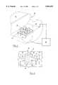
- FIG. 1is a diagrammatic illustration of a switching assembly designed according to this invention as it would be mounted within a vehicle.
- FIG. 2is a top elevational illustration of selected components of the switching assembly of FIG. 1.
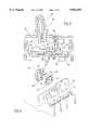
- FIG. 3is a partial cross-sectional illustration taken along the lines 3--3 from FIG. 2.
- FIG. 4shows the embodiment of FIG. 3 in another position.
- FIG. 5is a partial cross-sectional illustration taken along the lines 5--5 from FIG. 2.
- FIG. 6is a diagrammatic, exploded view of a preferred secondary switch contact designed according to this invention.
- FIG. 1diagrammatically illustrates a portion of a car door 20.
- a switching device 22is mounted on the door 20.
- the switching device 22enables a driver or passenger within the vehicle to control the position of the windows on the vehicle.
- An example window 24is illustrated.
- the power window assemblyincludes a motor 26 and an electronic controller 28.
- the electronic controller 28interfaces between the switching device 22 and the motor 26 so that the motor 26 accomplishes the desires of the driver of the vehicle, for example.
- FIGS. 2 and 3show a selected switch 29 of the switching device 22 in more detail.
- a switch handle 30is pivotally supported within a housing 32 so that the switch handle can be manipulated in a fore and aft direction as schematically illustrated by the arrow 34.
- the switch handleis moved to the left to lower a window and to the right (according to the drawing) to raise a window.
- the switch handle 30includes two plungers 36 and 38. These plungers serve as actuator portions for actuating primary switch contacts 40 and 42, which pivot about pivot supports 43A and 43B, respectively.
- the switch contact 40includes a normally open switch contact 44A at one end and a second end 45.
- the contact 44Acompletes a circuit when in contact with the fixed contact member 44B.
- the T switch contact 42includes a normally open switch contact 46A at one end and a second end 47.
- the contact 46Acompletes a circuit when in contact with the fixed contact member 46B.
- These fixed contact members 44B and 46Bare coupled to a circuit plate 48, which serves as a power supply for the switching device 22.
- the switch contacts 40 and 42are referred to as primary switch contacts because when they are actuated, the resulting action, as controlled by the controller 28, is considered the primary switching function.
- the primary switching functionwould be to raise or lower a window so long as the user manipulates the switch handle 30 so that the switch contact end 46 or 44 is closed, respectively.
- the plunger 38moves along a portion of the surface of the primary switch contact 42. Such movement of the plunger 38 causes the switch contact end 46 to be closed, which completes an appropriate circuit within the circuit plate 48 indicating to the electronic controller 28 that the window should be lowered from its current position. So long as the user holds the switch handle 30 in the position shown in FIG. 5, the plunger 38 keeps the normally open switch contact end 46 in a closed position and the electronic controller 28 continues to cause the motor 26 to lower the window.
- the switch device 22further includes a printed circuit board assembly 50 having a conductive contact portion 51.
- a header 52facilitates mounting the printed circuit board 50 in a perpendicular orientation relative to the circuit plate 48.
- the printed circuit board 50can be supported by the header 52 alone, or in combination with an interface between the printed circuit board 50 and other parts of the housing 32.
- the header 52facilitates an electrical connection between the printed circuit board 50 and the circuit plate 48.
- a soldered connection 54is provided between the printed circuit board 50 and the circuit plate 48.
- a generally flexible conductive member 56is supported adjacent the printed circuit board 50 by a retainer element 58.
- the retainer element 58is a piece of molded plastic.
- the generally flexible conductive memberpreferably is a dome-shaped piece of stainless steel.
- FIG. 6illustrates the conductive member 56 in greater detail.
- the flexible conductive member 56includes a central portion 60 and a plurality of arms or extensions 62 that project outwardly from the central portion 60.
- the central portion 60preferably has a convex surface on one side and a concave surface on an opposing side.
- the conductive member 56is mounted or supported adjacent the printed circuit board 50 so that the concave side of the central portion faces the printed circuit board 50.
- the arms 62preferably are received within slots 64 on the plastic retainer 58.
- the central portion 60 of the conductive member 56preferably protrudes at least partially through an opening 66 through a central part of the retainer 58.
- the switch handle 30also includes an actuator portion 70 that is oriented toward the flexible conductive member 56.
- the actuator 70When the switch handle 30 is moved to the left (according to the drawings) a sufficient distance, the actuator 70 will come into contact with the central portion 60 of the flexible conductive member 56. A sufficient amount of force placed on the switch handle 30 will result in the actuator 70 causing the central portion 60 to flex toward the printed circuit board 50. Once the central portion 60 is flexed sufficiently to contact the conductive contact portion 51 that completes a circuit resulting in the printed circuit board 50 generating a signal that is communicated to the electronic controller 28. Given this description, those skilled in the art will be able to choose a conductive contact portion 51 design having a contact arrangement suitable for a particular application.
- This signalindicates to the controller 28 that the user desires to accomplish a secondary switching function. Specifically, in this embodiment, the signal generated by the printed circuit board 50 indicates that the user desires the window to be lowered in an automatic mode.
- the perpendicular orientation of the printed circuit board 50 relative to the circuit plate 48provides the further advantage of serving as a mechanical stop for movement of the switch handle 30.
- varying the thickness of the flexible member 56 and/or the shape of the central portion 60readily provides customized operation characteristics.
- the movement of the switch handle 30 and the necessary effort required to accomplish the secondary switching functiondepends upon the shape and thickness of the flexible conductive member 56.
- the physical placement of the circuit board 50 relative to the pivot point of the switch handle 30controls the amount of movement required to accomplish a desired switching function.
- a switching device designed according to this inventionprovides the further advantages of simplifying and reducing the number of pieces or components required to accomplish a primary and secondary switching function.
- the overall switching deviceis readily adaptable to a variety of applications and allows for a compact design.
Landscapes
- Tumbler Switches (AREA)
Abstract
Description
Claims (18)
Priority Applications (4)
| Application Number | Priority Date | Filing Date | Title |
|---|---|---|---|
| US08/824,005US5854455A (en) | 1997-03-25 | 1997-03-25 | Switching device with secondary switching function |
| JP10545701AJP2000512072A (en) | 1997-03-25 | 1998-02-23 | Switching device having secondary switching function |
| PCT/US1998/003467WO1998043264A1 (en) | 1997-03-25 | 1998-02-23 | Switching device with secondary switching function |
| EP98907584AEP0902956A1 (en) | 1997-03-25 | 1998-02-23 | Switching device with secondary switching function |
Applications Claiming Priority (1)
| Application Number | Priority Date | Filing Date | Title |
|---|---|---|---|
| US08/824,005US5854455A (en) | 1997-03-25 | 1997-03-25 | Switching device with secondary switching function |
Publications (1)
| Publication Number | Publication Date |
|---|---|
| US5854455Atrue US5854455A (en) | 1998-12-29 |
Family
ID=25240358
Family Applications (1)
| Application Number | Title | Priority Date | Filing Date |
|---|---|---|---|
| US08/824,005Expired - Fee RelatedUS5854455A (en) | 1997-03-25 | 1997-03-25 | Switching device with secondary switching function |
Country Status (4)
| Country | Link |
|---|---|
| US (1) | US5854455A (en) |
| EP (1) | EP0902956A1 (en) |
| JP (1) | JP2000512072A (en) |
| WO (1) | WO1998043264A1 (en) |
Cited By (4)
| Publication number | Priority date | Publication date | Assignee | Title |
|---|---|---|---|---|
| US5981885A (en)* | 1997-11-26 | 1999-11-09 | Satori Electric Co., Ltd. | Operation-staggered dual switch |
| US20060071901A1 (en)* | 2004-10-05 | 2006-04-06 | Feldman Mark G | Graphic illumination for contact-less control |
| CN101339852B (en)* | 2007-07-03 | 2010-08-25 | 浙江加西亚电子电器有限公司 | Clamping construction |
| US20130220781A1 (en)* | 2012-02-29 | 2013-08-29 | Reliance Controls Corporation | Switch Assembly With Sequentially Actuated Power and Neutral Switching |
Families Citing this family (33)
| Publication number | Priority date | Publication date | Assignee | Title |
|---|---|---|---|---|
| US7364577B2 (en) | 2002-02-11 | 2008-04-29 | Sherwood Services Ag | Vessel sealing system |
| JP2005533607A (en) | 2002-07-25 | 2005-11-10 | シャーウッド・サービシーズ・アクチェンゲゼルシャフト | Electrosurgical pencil with drag detection |
| US7276068B2 (en) | 2002-10-04 | 2007-10-02 | Sherwood Services Ag | Vessel sealing instrument with electrical cutting mechanism |
| US7799026B2 (en) | 2002-11-14 | 2010-09-21 | Covidien Ag | Compressible jaw configuration with bipolar RF output electrodes for soft tissue fusion |
| AU2004212990B2 (en) | 2003-02-20 | 2009-12-10 | Covidien Ag | Motion detector for controlling electrosurgical output |
| US7160299B2 (en) | 2003-05-01 | 2007-01-09 | Sherwood Services Ag | Method of fusing biomaterials with radiofrequency energy |
| US9848938B2 (en) | 2003-11-13 | 2017-12-26 | Covidien Ag | Compressible jaw configuration with bipolar RF output electrodes for soft tissue fusion |
| US7367976B2 (en) | 2003-11-17 | 2008-05-06 | Sherwood Services Ag | Bipolar forceps having monopolar extension |
| US7241294B2 (en) | 2003-11-19 | 2007-07-10 | Sherwood Services Ag | Pistol grip electrosurgical pencil with manual aspirator/irrigator and methods of using the same |
| US7503917B2 (en) | 2003-11-20 | 2009-03-17 | Covidien Ag | Electrosurgical pencil with improved controls |
| US7837685B2 (en)* | 2005-07-13 | 2010-11-23 | Covidien Ag | Switch mechanisms for safe activation of energy on an electrosurgical instrument |
| US7722607B2 (en) | 2005-09-30 | 2010-05-25 | Covidien Ag | In-line vessel sealer and divider |
| CA2561034C (en) | 2005-09-30 | 2014-12-09 | Sherwood Services Ag | Flexible endoscopic catheter with an end effector for coagulating and transfecting tissue |
| US8235987B2 (en) | 2007-12-05 | 2012-08-07 | Tyco Healthcare Group Lp | Thermal penetration and arc length controllable electrosurgical pencil |
| US8663218B2 (en) | 2008-03-31 | 2014-03-04 | Covidien Lp | Electrosurgical pencil including improved controls |
| US8328804B2 (en) | 2008-07-24 | 2012-12-11 | Covidien Lp | Suction coagulator |
| US8182480B2 (en) | 2008-08-19 | 2012-05-22 | Tyco Healthcare Group Lp | Insulated tube for suction coagulator |
| US8016827B2 (en) | 2008-10-09 | 2011-09-13 | Tyco Healthcare Group Lp | Apparatus, system, and method for performing an electrosurgical procedure |
| US8114122B2 (en) | 2009-01-13 | 2012-02-14 | Tyco Healthcare Group Lp | Apparatus, system, and method for performing an electrosurgical procedure |
| US8454600B2 (en) | 2009-02-18 | 2013-06-04 | Covidien Lp | Two piece tube for suction coagulator |
| US8286339B2 (en) | 2009-02-18 | 2012-10-16 | Tyco Healthcare Group Lp | Two piece tube for suction coagulator |
| US8444641B2 (en) | 2009-02-18 | 2013-05-21 | Covidien Lp | Two piece tube for suction coagulator |
| US8460291B2 (en) | 2009-02-18 | 2013-06-11 | Covidien Lp | Two piece tube for suction coagulator |
| US8187273B2 (en) | 2009-05-07 | 2012-05-29 | Tyco Healthcare Group Lp | Apparatus, system, and method for performing an electrosurgical procedure |
| US8753341B2 (en) | 2009-06-19 | 2014-06-17 | Covidien Lp | Thermal barrier for suction coagulator |
| US8133254B2 (en) | 2009-09-18 | 2012-03-13 | Tyco Healthcare Group Lp | In vivo attachable and detachable end effector assembly and laparoscopic surgical instrument and methods therefor |
| US8112871B2 (en) | 2009-09-28 | 2012-02-14 | Tyco Healthcare Group Lp | Method for manufacturing electrosurgical seal plates |
| US9113940B2 (en) | 2011-01-14 | 2015-08-25 | Covidien Lp | Trigger lockout and kickback mechanism for surgical instruments |
| US9844384B2 (en) | 2011-07-11 | 2017-12-19 | Covidien Lp | Stand alone energy-based tissue clips |
| US20150324317A1 (en) | 2014-05-07 | 2015-11-12 | Covidien Lp | Authentication and information system for reusable surgical instruments |
| US10213250B2 (en) | 2015-11-05 | 2019-02-26 | Covidien Lp | Deployment and safety mechanisms for surgical instruments |
| US11564732B2 (en) | 2019-12-05 | 2023-01-31 | Covidien Lp | Tensioning mechanism for bipolar pencil |
| US11844562B2 (en) | 2020-03-23 | 2023-12-19 | Covidien Lp | Electrosurgical forceps for grasping, treating, and/or dividing tissue |
Citations (4)
| Publication number | Priority date | Publication date | Assignee | Title |
|---|---|---|---|---|
| US4117286A (en)* | 1975-06-13 | 1978-09-26 | J. & J. Marquardt | Electric switch |
| US4376237A (en)* | 1981-06-08 | 1983-03-08 | General Motors Corporation | Vehicle turn signal switch actuator |
| US4803316A (en)* | 1985-10-16 | 1989-02-07 | Fujitsu Limited | Push button switch using dome spring and switch element thereof |
| US5571998A (en)* | 1993-11-05 | 1996-11-05 | Nec Corporation | Function switching device for information processing apparatus |
Family Cites Families (4)
| Publication number | Priority date | Publication date | Assignee | Title |
|---|---|---|---|---|
| DE2848588C2 (en)* | 1978-11-09 | 1982-09-09 | Daut & Rietz KG Fabrik für Elektrofeinmechanik GmbH & Co, 8500 Nürnberg | Touch button |
| KR100281727B1 (en)* | 1993-08-13 | 2001-02-15 | 존 씨. 메티유 | Paddle Braid Switch Assembly with Stops |
| US5510583A (en)* | 1994-03-18 | 1996-04-23 | Eaton Corporation | Assembly for sequential switching |
| US5598918A (en)* | 1995-05-18 | 1997-02-04 | Trw Inc. | Switch for vehicle power window |
- 1997
- 1997-03-25USUS08/824,005patent/US5854455A/ennot_activeExpired - Fee Related
- 1998
- 1998-02-23WOPCT/US1998/003467patent/WO1998043264A1/ennot_activeApplication Discontinuation
- 1998-02-23EPEP98907584Apatent/EP0902956A1/ennot_activeWithdrawn
- 1998-02-23JPJP10545701Apatent/JP2000512072A/enactivePending
Patent Citations (4)
| Publication number | Priority date | Publication date | Assignee | Title |
|---|---|---|---|---|
| US4117286A (en)* | 1975-06-13 | 1978-09-26 | J. & J. Marquardt | Electric switch |
| US4376237A (en)* | 1981-06-08 | 1983-03-08 | General Motors Corporation | Vehicle turn signal switch actuator |
| US4803316A (en)* | 1985-10-16 | 1989-02-07 | Fujitsu Limited | Push button switch using dome spring and switch element thereof |
| US5571998A (en)* | 1993-11-05 | 1996-11-05 | Nec Corporation | Function switching device for information processing apparatus |
Cited By (5)
| Publication number | Priority date | Publication date | Assignee | Title |
|---|---|---|---|---|
| US5981885A (en)* | 1997-11-26 | 1999-11-09 | Satori Electric Co., Ltd. | Operation-staggered dual switch |
| US20060071901A1 (en)* | 2004-10-05 | 2006-04-06 | Feldman Mark G | Graphic illumination for contact-less control |
| CN101339852B (en)* | 2007-07-03 | 2010-08-25 | 浙江加西亚电子电器有限公司 | Clamping construction |
| US20130220781A1 (en)* | 2012-02-29 | 2013-08-29 | Reliance Controls Corporation | Switch Assembly With Sequentially Actuated Power and Neutral Switching |
| US9035204B2 (en)* | 2012-02-29 | 2015-05-19 | Reliance Controls Corporation | Switch assembly with sequentially actuated power and neutral switching |
Also Published As
| Publication number | Publication date |
|---|---|
| EP0902956A1 (en) | 1999-03-24 |
| JP2000512072A (en) | 2000-09-12 |
| WO1998043264A1 (en) | 1998-10-01 |
Similar Documents
| Publication | Publication Date | Title |
|---|---|---|
| US5854455A (en) | Switching device with secondary switching function | |
| EP1463077B1 (en) | Two-step switch device | |
| US5950813A (en) | Electrical switch | |
| US5844182A (en) | Power seat switch mechanism including actuators for selectively operating switches | |
| US5923522A (en) | Capacitive switch with elastomeric membrane actuator | |
| CA1329413C (en) | Remote power mirror switch assembly | |
| US5902972A (en) | Three function rocker/push switch | |
| EP1081730B1 (en) | Rocker switch | |
| JP3108011B2 (en) | Device for controlling the movement of the power window | |
| US5626223A (en) | Cam-assisted switch | |
| US5689095A (en) | Switching device | |
| CA2099688A1 (en) | Multiple circuit switch with improved multi-position for joypad actuator | |
| GB2423418A (en) | A switch assembly for a vehicle | |
| US4453063A (en) | Keyswitch configuration with torque rod holder | |
| EP0654806A1 (en) | Detented rocker switch | |
| US7569786B2 (en) | Actuator for an electric push-button switch, particularly in vehicles | |
| JPH05225861A (en) | Low-tension current changeover device and its manufacture | |
| US7528335B2 (en) | Light assembly for vehicle interiors | |
| JP2008539558A (en) | Switching apparatus and method | |
| US3222472A (en) | Turn signal switch for a tiltable steering wheel | |
| US5389754A (en) | Printed circuit board mounted guide system | |
| EP0758133A2 (en) | Precision double-pole single-throw switch assembly | |
| EP1294000B1 (en) | An electrical double snap-action lamina switch | |
| EP3312863B1 (en) | Switch device in particular for a use in a push pull window lifter mechanism | |
| US5595285A (en) | Axially operated switch for electrical circuits |
Legal Events
| Date | Code | Title | Description |
|---|---|---|---|
| AS | Assignment | Owner name:UNITED TECHNOLOGIES AUTOMOTIVE, INC., MICHIGAN Free format text:ASSIGNMENT OF ASSIGNORS INTEREST;ASSIGNORS:CRANICK, JOHN;FELDMAN, MARK;REEL/FRAME:008697/0504 Effective date:19970326 | |
| AS | Assignment | Owner name:UT AUTOMOTIVE DEARBORN, INC., MICHIGAN Free format text:ASSIGNMENT OF ASSIGNORS INTEREST;ASSIGNOR:UNITED TECHNOLOGIES AUTOMOTIVE, INC.;REEL/FRAME:009083/0924 Effective date:19980330 | |
| FEPP | Fee payment procedure | Free format text:PAYOR NUMBER ASSIGNED (ORIGINAL EVENT CODE: ASPN); ENTITY STATUS OF PATENT OWNER: LARGE ENTITY | |
| FPAY | Fee payment | Year of fee payment:4 | |
| REMI | Maintenance fee reminder mailed | ||
| AS | Assignment | Owner name:LEAR AUTOMOTIVE DEARBORN, INC., MICHIGAN Free format text:CHANGE OF NAME;ASSIGNOR:UT AUTOMOTIVE DEARBORN, INC.;REEL/FRAME:014172/0756 Effective date:19990617 | |
| AS | Assignment | Owner name:JPMORGAN CHASE BANK, N.A., AS GENERAL ADMINISTRATI Free format text:SECURITY AGREEMENT;ASSIGNOR:LEAR AUTOMOTIVE DEARBORN, INC.;REEL/FRAME:017823/0950 Effective date:20060425 | |
| FPAY | Fee payment | Year of fee payment:8 | |
| AS | Assignment | Owner name:JPMORGAN CHASE BANK, N.A., AS ADMINISTRATIVE AGENT Free format text:GRANT OF FIRST LIEN SECURITY INTEREST IN PATENT RIGHTS;ASSIGNOR:LEAR AUTOMOTIVE DEARBORN, INC.;REEL/FRAME:023519/0683 Effective date:20091109 Owner name:JPMORGAN CHASE BANK, N.A., AS ADMINISTRATIVE AGENT Free format text:GRANT OF SECOND LIEN SECURITY INTEREST IN PATENT RIGHTS;ASSIGNOR:LEAR AUTOMOTIVE DEARBORN, INC.;REEL/FRAME:023519/0699 Effective date:20091109 | |
| REMI | Maintenance fee reminder mailed | ||
| LAPS | Lapse for failure to pay maintenance fees | ||
| STCH | Information on status: patent discontinuation | Free format text:PATENT EXPIRED DUE TO NONPAYMENT OF MAINTENANCE FEES UNDER 37 CFR 1.362 | |
| AS | Assignment | Owner name:LEAR AUTOMOTIVE DEARBORN, INC., MICHIGAN Free format text:RELEASE BY SECURED PARTY;ASSIGNOR:JPMORGAN CHASE BANK, N.A.;REEL/FRAME:032712/0676 Effective date:20100830 Owner name:LEAR AUTOMOTIVE DEARBORN, INC., MICHIGAN Free format text:RELEASE BY SECURED PARTY;ASSIGNOR:JPMORGAN CHASE BANK, N.A.;REEL/FRAME:032712/0428 Effective date:20100830 |