US5854074A - Dispensing instrument for fluid monitoring sensors - Google Patents
Dispensing instrument for fluid monitoring sensorsDownload PDFInfo
- Publication number
- US5854074A US5854074AUS08/785,185US78518597AUS5854074AUS 5854074 AUS5854074 AUS 5854074AUS 78518597 AUS78518597 AUS 78518597AUS 5854074 AUS5854074 AUS 5854074A
- Authority
- US
- United States
- Prior art keywords
- sensor
- actuator
- driver
- pack
- testing
- Prior art date
- Legal status (The legal status is an assumption and is not a legal conclusion. Google has not performed a legal analysis and makes no representation as to the accuracy of the status listed.)
- Expired - Lifetime
Links
- 239000012530fluidSubstances0.000titleclaimsabstractdescription29
- 238000012544monitoring processMethods0.000titledescription4
- 238000012360testing methodMethods0.000claimsabstractdescription94
- 239000011888foilSubstances0.000claimsabstractdescription40
- 230000002093peripheral effectEffects0.000claimsdescription12
- 238000000034methodMethods0.000claimsdescription4
- 239000008280bloodSubstances0.000abstractdescription40
- 210000004369bloodAnatomy0.000abstractdescription40
- WQZGKKKJIJFFOK-GASJEMHNSA-NGlucoseNatural productsOC[C@H]1OC(O)[C@H](O)[C@@H](O)[C@@H]1OWQZGKKKJIJFFOK-GASJEMHNSA-N0.000abstractdescription26
- 239000008103glucoseSubstances0.000abstractdescription26
- 239000002274desiccantSubstances0.000abstractdescription17
- 238000004891communicationMethods0.000abstractdescription3
- 239000000463materialSubstances0.000description22
- 239000004973liquid crystal related substanceSubstances0.000description12
- 238000012545processingMethods0.000description12
- 239000003153chemical reaction reagentSubstances0.000description11
- 239000000523sampleSubstances0.000description10
- 229910001220stainless steelInorganic materials0.000description4
- 239000010935stainless steelSubstances0.000description4
- 238000012956testing procedureMethods0.000description4
- 239000000853adhesiveSubstances0.000description2
- 230000001070adhesive effectEffects0.000description2
- 230000002411adverseEffects0.000description2
- 239000011324beadSubstances0.000description2
- 230000009172burstingEffects0.000description2
- 230000000994depressogenic effectEffects0.000description2
- NOESYZHRGYRDHS-UHFFFAOYSA-NinsulinChemical compoundN1C(=O)C(NC(=O)C(CCC(N)=O)NC(=O)C(CCC(O)=O)NC(=O)C(C(C)C)NC(=O)C(NC(=O)CN)C(C)CC)CSSCC(C(NC(CO)C(=O)NC(CC(C)C)C(=O)NC(CC=2C=CC(O)=CC=2)C(=O)NC(CCC(N)=O)C(=O)NC(CC(C)C)C(=O)NC(CCC(O)=O)C(=O)NC(CC(N)=O)C(=O)NC(CC=2C=CC(O)=CC=2)C(=O)NC(CSSCC(NC(=O)C(C(C)C)NC(=O)C(CC(C)C)NC(=O)C(CC=2C=CC(O)=CC=2)NC(=O)C(CC(C)C)NC(=O)C(C)NC(=O)C(CCC(O)=O)NC(=O)C(C(C)C)NC(=O)C(CC(C)C)NC(=O)C(CC=2NC=NC=2)NC(=O)C(CO)NC(=O)CNC2=O)C(=O)NCC(=O)NC(CCC(O)=O)C(=O)NC(CCCNC(N)=N)C(=O)NCC(=O)NC(CC=3C=CC=CC=3)C(=O)NC(CC=3C=CC=CC=3)C(=O)NC(CC=3C=CC(O)=CC=3)C(=O)NC(C(C)O)C(=O)N3C(CCC3)C(=O)NC(CCCCN)C(=O)NC(C)C(O)=O)C(=O)NC(CC(N)=O)C(O)=O)=O)NC(=O)C(C(C)CC)NC(=O)C(CO)NC(=O)C(C(C)O)NC(=O)C1CSSCC2NC(=O)C(CC(C)C)NC(=O)C(NC(=O)C(CCC(N)=O)NC(=O)C(CC(N)=O)NC(=O)C(NC(=O)C(N)CC=1C=CC=CC=1)C(C)C)CC1=CN=CN1NOESYZHRGYRDHS-UHFFFAOYSA-N0.000description2
- 238000004519manufacturing processMethods0.000description2
- 239000002184metalSubstances0.000description2
- 239000004033plasticSubstances0.000description2
- 230000000717retained effectEffects0.000description2
- 238000007789sealingMethods0.000description2
- 238000010998test methodMethods0.000description2
- 102000004877InsulinHuman genes0.000description1
- 108090001061InsulinProteins0.000description1
- WYTGDNHDOZPMIW-RCBQFDQVSA-NalstonineNatural productsC1=CC2=C3C=CC=CC3=NC2=C2N1C[C@H]1[C@H](C)OC=C(C(=O)OC)[C@H]1C2WYTGDNHDOZPMIW-RCBQFDQVSA-N0.000description1
- 230000000295complement effectEffects0.000description1
- 239000004020conductorSubstances0.000description1
- 230000001419dependent effectEffects0.000description1
- 230000000881depressing effectEffects0.000description1
- 206010012601diabetes mellitusDiseases0.000description1
- 229940079593drugDrugs0.000description1
- 239000003814drugSubstances0.000description1
- 230000009977dual effectEffects0.000description1
- 238000009459flexible packagingMethods0.000description1
- 229940125396insulinDrugs0.000description1
- 230000013011matingEffects0.000description1
- 239000002991molded plasticSubstances0.000description1
- 238000004806packaging method and processMethods0.000description1
- 239000008188pelletSubstances0.000description1
- 239000000843powderSubstances0.000description1
- 229920002379silicone rubberPolymers0.000description1
Images


Classifications
- G—PHYSICS
- G01—MEASURING; TESTING
- G01N—INVESTIGATING OR ANALYSING MATERIALS BY DETERMINING THEIR CHEMICAL OR PHYSICAL PROPERTIES
- G01N1/00—Sampling; Preparing specimens for investigation
- G—PHYSICS
- G01—MEASURING; TESTING
- G01N—INVESTIGATING OR ANALYSING MATERIALS BY DETERMINING THEIR CHEMICAL OR PHYSICAL PROPERTIES
- G01N33/00—Investigating or analysing materials by specific methods not covered by groups G01N1/00 - G01N31/00
- G01N33/48—Biological material, e.g. blood, urine; Haemocytometers
- G01N33/483—Physical analysis of biological material
- G01N33/487—Physical analysis of biological material of liquid biological material
- G01N33/4875—Details of handling test elements, e.g. dispensing or storage, not specific to a particular test method
- B—PERFORMING OPERATIONS; TRANSPORTING
- B01—PHYSICAL OR CHEMICAL PROCESSES OR APPARATUS IN GENERAL
- B01L—CHEMICAL OR PHYSICAL LABORATORY APPARATUS FOR GENERAL USE
- B01L99/00—Subject matter not provided for in other groups of this subclass
- G—PHYSICS
- G01—MEASURING; TESTING
- G01N—INVESTIGATING OR ANALYSING MATERIALS BY DETERMINING THEIR CHEMICAL OR PHYSICAL PROPERTIES
- G01N35/00—Automatic analysis not limited to methods or materials provided for in any single one of groups G01N1/00 - G01N33/00; Handling materials therefor
- G01N35/00029—Automatic analysis not limited to methods or materials provided for in any single one of groups G01N1/00 - G01N33/00; Handling materials therefor provided with flat sample substrates, e.g. slides
- G01N2035/00089—Magazines
- Y—GENERAL TAGGING OF NEW TECHNOLOGICAL DEVELOPMENTS; GENERAL TAGGING OF CROSS-SECTIONAL TECHNOLOGIES SPANNING OVER SEVERAL SECTIONS OF THE IPC; TECHNICAL SUBJECTS COVERED BY FORMER USPC CROSS-REFERENCE ART COLLECTIONS [XRACs] AND DIGESTS
- Y10—TECHNICAL SUBJECTS COVERED BY FORMER USPC
- Y10T—TECHNICAL SUBJECTS COVERED BY FORMER US CLASSIFICATION
- Y10T436/00—Chemistry: analytical and immunological testing
- Y10T436/11—Automated chemical analysis
- Y10T436/110833—Utilizing a moving indicator strip or tape
- Y—GENERAL TAGGING OF NEW TECHNOLOGICAL DEVELOPMENTS; GENERAL TAGGING OF CROSS-SECTIONAL TECHNOLOGIES SPANNING OVER SEVERAL SECTIONS OF THE IPC; TECHNICAL SUBJECTS COVERED BY FORMER USPC CROSS-REFERENCE ART COLLECTIONS [XRACs] AND DIGESTS
- Y10—TECHNICAL SUBJECTS COVERED BY FORMER USPC
- Y10T—TECHNICAL SUBJECTS COVERED BY FORMER US CLASSIFICATION
- Y10T436/00—Chemistry: analytical and immunological testing
- Y10T436/11—Automated chemical analysis
- Y10T436/112499—Automated chemical analysis with sample on test slide
Definitions
- the present inventiongenerally relates to a fluid monitoring system, and, more particularly, to a new and improved instrument for handling multiple sensors that are used in analyzing blood glucose or other analytes contained therein.
- sensorsare used to test a sample of blood.
- Such a sensormay have a generally flat, rectangular shape with a front or testing end and a rear or contact end.
- the sensorcontains biosensing or reagent material that will react with blood glucose.
- the testing end of the sensoris adapted to be placed into the fluid being tested, for example, blood that has accumulated on a person's finger after the finger has been pricked.
- the fluidis drawn into a capillary channel that extends in the sensor from the testing end to the reagent material by capillary action so that a sufficient amount of fluid to be tested is drawn into the sensor.
- the fluidthen chemically reacts with the reagent material in the sensor with the result that an electrical signal indicative of the blood glucose level in the blood being tested is supplied to contact areas located near the rear or contact end of the sensor.
- the sensorsIn order to couple the electrical signals produced at the sensor contacts to monitoring equipment, the sensors need to be inserted into sensor holders prior to the sensor end being placed into the fluid being tested.
- the holdershave corresponding mating contact areas that become coupled to the contacts on the sensor when the sensor is inserted into the holder. Consequently, the holders act as an interface between the sensor and monitoring equipment that accumulates and/or analyzes the test results.
- the sensorsPrior to being used, the sensors need to be maintained at an appropriate humidity level so as to insure the integrity of the reagent materials in the sensor.
- Sensorscan be packaged individually in tearaway packages so that they can be maintained at the proper humidity level.
- blister type packaging methodscould be used.
- the packagescan include desiccant material to maintain the proper humidity or desiccate level in the package.
- the packageIn order for a person to use an individual sensor for testing blood glucose, the package must be opened by tearing the seal. Alternatively, some packages require the user to exert force against one side of the package resulting in the sensor bursting or rupturing the foil on the other side. As can be appreciated, the opening of these packages can be difficult. Moreover, once the package is opened, the user needs to be sure that the sensor is not damaged or contaminated as it is being placed into the sensor holder and used to test the blood sample.
- an object of the present inventionis to provide a new and improved sensor pack of multiple sensors used in testing blood glucose and a dispensing instrument for handling the sensors contained in such sensor packs.
- objects of the present inventionare to provide a new and improved fluid sensor dispensing instrument handling device that is adapted to receive a sensor pack containing a plurality of fluid sensors so that individual sensors can be selectively placed in a testing position when a feed actuator on the sensor dispensing instrument is moved to a testing position and to automatically index the sensor pack while the feed actuator is being returned to its standby position so that another one of the sensors can be placed into a testing position; to provide a new and improved fluid sensor dispensing instrument having a cutting device pivotally mounted on a driver device with the cutting device ejecting sensors from a sensor pack so as to position the ejected sensor in a testing position and being displaced from the sensor pack as the driver device is returned to a standby position; to provide a new and improved fluid sensor dispensing instrument having a sensor pack with a plurality of
- the present inventionis embodied in a sensor dispensing instrument that is adapted to receive a sensor pack containing a plurality of blood glucose sensors.
- a sensor packcontaining a plurality of blood glucose sensors.
- Each of the sensorshas a generally flat, rectangular shape with a front testing end through which fluid is drawn so as to react with a reagent material in the sensor and an opposite rear, contact end.
- the sensor packincludes a generally circular shaped base portion in which is formed sensor retaining cavities or depressions. Each of the sensor retaining cavities is adapted to receive one of the sensors and is in fluid communication with a corresponding desiccant cavity in which is disposed desiccant material.
- the desiccant materialis placed in the cavity to insure that the corresponding sensor cavity is maintained at an appropriate humidity or desiccate level so that the reagent material in the sensors will not be adversely affected prior to the sensors being used.
- a foilis heat sealed onto the base portion about the entire outer peripheral edge of the base portion and about the entire perimeter of each set of sensor retaining and desciccant cavities to seal the sensor retaining cavities and the desiccant cavities such that the individual sensors are maintained in a desiccated state and isolated from each other. As a result, the opening of one sensor cavity will not affect the desiccated state of any other sensor cavity.
- Each of the sensor cavitieshas a support wall on which the individual sensor lies when the sensor is disposed in the sensor cavity.
- the support wallextends in a radial direction from adjacent the peripheral edge of the base portion toward a center of the base portion.
- the support wallincludes a sloped or inclined portion that is sloped toward the foil sealing the base portion in a direction toward the peripheral edge of the base portion.
- the sensor packadditionally includes a series of notches formed along the outer circumferential edge of the sensor pack with each of the notches corresponding to one of the sensor cavities.
- the sensor instrumentincludes an outer housing having an upper case and a lower case with the upper and lower cases being pivotable with respect to each other in a clam shell fashion so that the sensor pack can be positioned in the housing on an indexing disk disposed in the housing.
- a slide latch on a slide actuator disposed on the upper case of the housingcontrols whether the movement of the slide actuator places the instrument in a display or data processing mode or in a testing mode.
- the instrumentis placed into its display mode when the slide latch is moved laterally and the slide actuator is pushed away from its standby position.
- a person using the instrumentcan view data displayed on a display unit in the upper case and/or input data into the instrument.
- the instrumentis in its testing mode when the slide latch is in its normal position and the slide actuator is pushed towards its testing position.
- a feeding mechanism engaged by the slide actuator inside the upper case of the housingalso is moved from its standby position toward a testing position.
- the feeding mechanismincludes a driver on which is pivotally mounted a knife blade and from which extends an indexing disk drive arm. As the slide actuator is moved towards its actuated position, the driver with the knife blade thereon moves toward the testing position of the feed mechanism and the disk drive arm travels in a straight, radially extending groove in the indexing disk such that the disk is not rotated as the feeding mechanism is moving towards its testing position.
- the knife bladehas cam followers that ride on a first portion of a cam track and under a lift spring as the driver starts to move away from its standby position.
- the first portion of the trackis inclined toward the sensor pack so that the knife blade is moved towards one of the sensor cavities in the sensor pack positioned on the indexing disk.
- the knife bladepierces the foil covering the sensor cavity in alignment with the knife blade and engages the sensor disposed in the cavity.
- the knife bladefurther severs the foil covering the sensor cavity and forces or ejects the sensor out from the sensor cavity such that a front biased edge of the sensor bursts through the outer foil covering the sensor cavity.
- the sensorAs the sensor is being forced out of the sensor cavity, the sensor travels along the sloped support wall of the sensor cavity so that as the sensor is advanced by the knife blade, the sensor will avoid being forced into the heat seal that affixes the foil to the base portion of the sensor pack.
- the force required to move the sensor through the foilis minimized by the pointed, biased geometry of the front of the sensor so that the sensor cuts an exit hole through the foil rather than merely stretching it.
- the continued sliding of the slide actuator toward its testing positionresults in the sensor being completely ejected from the sensor cavity.
- a guide disposed near the testing end of the sensor housingguides the sensor from the sensor cavity into a testing position.
- cam surfaces on the front of the driverengage a sensor actuator that maintains the sensor in its testing position with the testing end of the sensor projecting out from the testing end of the housing.
- the sensor actuatorincludes contacts that become mated with corresponding contacts on the sensor.
- the sensor dispensing instrumentmay include a microprocessor or other data processing circuitry that is likewise electrically coupled to the sensor actuator so that data obtained from the sensor when it is inserted into blood to be tested can be processed. The processed data then can be displayed on a screen in the upper case of the instrument or stored for use in other analyzing equipment.
- the slide actuatoris moved in the opposite direction towards its standby position.
- the drivermoves away from the sensor actuator so that the contacts on the sensor actuator move away from the corresponding contacts on the sensor and the sensor can be removed from the dispensing instrument.
- the continued retraction of the driverresults in the cam followers on the knife assembly to ride onto the lift spring so that the knife blade is moved away from the sensor pack allowing the indexing disk to advance the sensor pack.
- the indexing disk drive arm extending from the driverbegins to travel along a curvilinearly extending groove that is interconnected to the radially extending groove in the indexing disk resulting in the rotation of the indexing disk.
- the rotation of the indexing diskalso results in the sensor pack being rotated so that the next one of sensor cavities is positioned in alignment with the knife blade so that the sensor in the sensor cavity can be used for the next blood glucose test that is to be performed.
- the dispensing instrumentincludes calibration circuitry with probes that contact a label on the sensor pack when the sensor pack is mounted on the indexing disk.
- the calibration circuitryprovides the data processor with data as to the sensor pack and the tests performed with the sensors in the sensor pack.
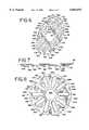
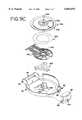
- FIG. 1is a perspective view of a blood glucose sensor dispensing instrument embodying the present invention
- FIG. 2is a top plan view of the blood glucose sensor dispensing instrument of FIG. 1;
- FIG. 3is a bottom plan view of the blood glucose sensor dispensing instrument of FIG. 1;
- FIG. 4is a perspective view of the blood glucose sensor dispensing instrument of FIG. 1 shown with a sensor in a testing position;
- FIG. 5is an exploded perspective view of a sensor pack used in the blood glucose sensor dispensing instrument of FIG. 1 with the foil portion of the sensor pack separated from the base portion of the sensor pack;
- FIG. 6is top view of the base portion of the sensor pack of FIG. 5;
- FIG. 7is side view of the base portion of the sensor pack of FIG. 5;
- FIG. 8is bottom view of the base portion of the sensor pack of FIG. 5.
- FIGS. 9A-9Care exploded perspective views of the component parts of the sensor dispensing instrument of FIG. 1.
- the sensor dispensing instrument 30includes an outer housing 32 having an upper case 34 and a lower case 36.
- the upper case 34is pivotable with respect to the lower case 36 in a clam shell fashion so that a sensor pack 38 (FIGS. 5-8) can be positioned on an indexing disk 40 within the housing 32.
- a slide actuator 42 on the upper case 34 of the housing 32can be moved to engage a feed mechanism, generally designated by the numeral 44 (FIG. 9B), secured to the inside of the upper case 34 as the slide actuator 42 manually is pushed from a standby position (FIGS.
- the slide actuator 42also can be moved to place the sensor dispensing instrument 30 in a data processing or display mode.
- the feed mechanism 44includes a driver 50 on which is pivotally mounted a knife blade assembly 52, from which extends an indexing disk drive arm 54 and on which is mounted a biasing spring 56.
- a driver 50on which is pivotally mounted a knife blade assembly 52, from which extends an indexing disk drive arm 54 and on which is mounted a biasing spring 56.
- the driver 50 with the knife blade assembly 52 thereonmoves toward the testing end 48 and a button 58 at the distal end of the disk drive arm 54 travels in one of a plurality of radially extending grooves 60A-J in the indexing disk 40 such that the indexing disk 40 is not rotated while the driver 50 is being moved towards its testing position.
- a knife blade 62 on the knife blade assembly 52pierces a portion of a foil 64 covering one of a plurality of sensor cavities 66A-J, such as the cavity 66F, in a base portion 68 of the sensor pack 38 in alignment with the knife blade 62.
- a sensor 70 disposed in the cavity 66Ais engaged by the knife blade 62 resulting in the knife blade 62 further severing the foil 64 covering the sensor cavity 66F and forcing or ejecting the sensor 70 out from the sensor cavity 66F.
- the driver 50engages a contact end 72 of a sensor actuator 74 that is forced against the sensor 70 to thereby maintain the sensor 70 in a testing position projecting out from the testing end 48 (FIG. 4).
- the sensor actuator 74couples the sensor 70 to electronic circuitry on a printed circuit board 76 disposed in the upper case 34.
- the circuitry on the printed circuit board 76may include a microprocessor or the like for processing, storing and/or displaying data generated during a blood glucose test procedure.
- the slide actuator 42is manually retracted in the opposite direction towards its standby position adjacent the rear end 46 of the upper case 34 and the sensor 70 is released from the contact end 72 of the sensor actuator 74 so that the sensor 70 can be removed from the housing 32.
- the driver 50is similarly returned towards the rear end 46 such that the button 58 on the disk drive arm 54 begins to travel along one of a plurality of curvilinearly extending grooves 80A-J, such as groove 80A that is interconnected to the radially extending groove 60A, resulting in the rotation of the indexing disk 40.
- the rotation of the indexing disk 40also results in the sensor pack 38 being rotated so that the next one of sensor cavities 66A-J is positioned in alignment with the knife blade 62 so that the sensor 70 in the next sensor cavity 66E can be used in the next blood glucose testing procedure.
- the upper case 34 and the lower case 36 of the sensor dispensing housing 32are complementary, generally round in shape hollow containers that are adapted to be pivoted with respect to each other about pivot pins 82 extending outwardly in a rear section 84 of the lower case 36 into pivot holes 86 in a rear section 88 of the upper case 34.
- the upper case 34 and the lower case 36are maintained in their closed configuration as shown in FIGS. 1-4 by a latch 90 that is pivotally mounted in a front or testing section 92 of the lower case 36 by pins 94 that extend inwardly into pivot holes 96 in the latch 90.
- the latch 90When the latch 90 is pivoted upwardly, it clips into a recess 98 in a front or testing end section 100 of the upper case 34 thereby securing the upper case 34 and the lower case 36 in their closed configuration.
- the upper case 34has a recess 102 that extends in its exterior upper wall 104 from the front section 100 to adjacent the rear section 88.
- the slide actuator 42is adapted to be mounted within the recess 102 so that side extending shoulders 106 slide within opposite grooves 108 along the edges of the recess 102.
- a slide latch 110is held in position on the slide actuator 42 by a slide clip 112 that is positioned on the under side of the slide actuator 42, includes a clip 114 that extends through an opening 116 in the recess 102, clips onto the slide actuator 42 and has an mode actuator 118.
- the slide latch 110includes a plurality of raised nubs 120 that provides a surface facilitating the movement of the slide latch 110 and the slide actuator 42 by a person using the sensor dispensing instrument 30.
- the movement of the slide latch 110places the instrument in one of two operating modes. In a first or testing mode, the slide latch 110 is positioned as shown in FIGS. 1, 2 and 4. In a second or data processing mode, the slide latch 110 is slid laterally with respect to the slide actuator 42.
- a C-shaped catch 122 on the lower portion of the slide latch 110is positioned in a longitudinal extending portion 124 of an opening 126 in the slide actuator 42 (see FIG. 9A).
- the catch 122projects through a slot 128 in the recess 102 so as to engage a post 130 extending upward from the driver 50 as the slide actuator 42 is moved toward the testing end 48.
- the C-shaped catch 122 on the lower portion of the slide latch 110is disposed in a laterally extending portion 132 of the opening 126 so that the catch 122 moves within a slot 133 as the slide actuator 42 is moved toward the testing end 48 in the data processing mode of the sensor dispensing instrument 30.
- the catch 122does not engage the post 130 when instrument 30 is in its data processing mode.
- the upper case 34includes a rectangular opening 134 in the rear section 88.
- a lens 136is positioned in the opening 134 such that a liquid crystal display unit 138 attached below the lens 136 is visible through the lens 136 when the slide actuator 42 is moved away from the rear end 46 of the upper case 34.
- the liquid crystal display unit 138is coupled to circuits on the printed circuit board 76 via connectors 140 and 142.
- the displays appearing on the liquid crystal display unit 138 when the instrument 30 is in its data processing or display modeare controlled by an actuating button 143 and a corresponding pad 144 and an actuating button 146 and a corresponding pad 147 that are disposed in the rear end 46.
- the buttons 143 and 146can be depressed to view and/or input the testing information that will be displayed on the liquid crystal display unit 138.
- the upper case 34also contains a battery holder 148 in which a pair of batteries 150 and 152 are disposed.
- the holder 148is inserted into a side 149 of the upper case 34 adjacent the front section 100.
- the batteries 150 and 152provide power for the electronics within the instrument 30 including the circuitry on the printed circuit board 76 and the liquid crystal display unit 138.
- two actuating switches 154 and 156are provided. Both of the switches 154 and 156 extend through openings 158 and 160 respectively in the recess 102.
- the mode actuator 118 on the slide clip 112will activate both of the switches 154 and 156 to thereby place the instrument 30 in its testing mode.
- the mode actuator 118only will activate the switch 154 when the slide latch 110 is moved laterally to its display position and the slide actuator 42 is moved toward the front end 48.
- the instrument 30will be in its display mode when only the switch 154 and not the switch 156 is actuated by the mode actuator 110, but in its testing mode when both of the switches 154 and 156 are activated.
- a block guide 162the printed circuit board 76, the sensor actuator 74, a housing guide 164, a knife spring 166, the knife assembly 52 and the driver 50 are held together and secured to the upper case 34 by fasteners 168-171 that extend through those components and into the upper case 34 (see FIG. 9B).
- the indexing disk 40is secured relative to the upper case 34 by being rotatably retained on the housing guide 164 by a retainer 172 that has a pair of latch arms 174 and 176 extending through a central hole 178 in the indexing disk 40 and latching into an opening 180 in the housing guide 164.
- the driver 50is advanced toward the front or testing end 48 of the upper case 34 when the C-shaped clip 122 on the slide latch 110 engages the driver post 130 as the slide actuator 42 is advanced toward the testing end 48 by a person using the instrument 30.
- the driver 50is a molded plastic component having a central recess 182 extending longitudinally to an enlarged recess 184 adjacent a forward edge 186 of the driver 50.
- a pair of cam projections 188 and 190extend from the forward edge 186 and are adapted to engage the contact end 72 of the sensor actuator 74 as the driver 50 is pushed forwarded during a testing procedure.
- the driver 50includes opposed recesses 192 extending outwardly from the recess 182 in which opposed pivot pins 194 and 196 on the knife blade assembly 52 are disposed.
- the knife blade assembly 52is pivotably mounted on the driver 50 such that opposed cam followers 198 and 200 projecting from opposite sides of the knife blade assembly 52 can extend positioned through the enlarged recess 184 near the forward edge 186 of the driver 52.
- the cam followers 198 and 200are adapted to travel along cam surfaces 202 and 204 formed on the block guide 162.
- the driver 50also includes the indexing disk drive arm 54 that extends rearwardly from the driver 50.
- the indexing disk drive arm 54is made of spring type material such as stainless steel so that the button 58 affixed at the distal end of the arm 54 can travel in one of the radially extending grooves 60A-J in the indexing disk 40 when the driver 50 is being advanced toward the front end 48 or in one of the curvilinearly extending grooves 80A-J in the indexing disk 40 when the driver 50 is being returned toward the rear end 46 of the upper case 34.
- the biasing spring 56is positioned on the driver 50 above the knife blade assembly 52 and exerts a downward force on the knife blade assembly 52.
- the cam followers 198 and 200also will be extend through an enlarged recess 206 of a longitudinally extending slot 208 in the knife spring 166 when the recess 184 is in alignment with the recess 206.
- the knife spring 166is positioned below the driver 50 and includes spring legs 210 and 212 on either side of the slot 208.
- the spring leg 210has a ramp portion 214 and the spring leg 216 has a ramp portion 216.
- cam followers 198 and 200ride up onto the ramp portions 214 and 216 respectively as the driver 50 is being returned toward the rear end 46 to thereby lift the knife assembly 52 and in particularly the knife blade 62 away from the sensor pack 38 disposed on the indexing disk 40 as the knife assembly 52 is being returned toward the rear end 46 with the driver 50.
- the driver 50is mounted on the housing guide 164 which is secured to the block guide 162 such that the sensor actuator 74 and the printed circuit board 76 are sandwiched therebetween.
- the housing guide 164includes a rear frame portion 218 in which the lens 136 and liquid crystal display unit 138 are disposed.
- a guide rail portion 220extends from the rear frame portion 218 toward a front end 219 of the housing guide 164.
- the guide rail portion 220has two forwardly extending rails 222 and 224 with fastening holes 226-229 located at the outer ends of the rails 222 and 224.
- the fasteners 168-171extend respectively through the holes 226-229.
- the rail 222has an upper cam track 230 and the rail 224 has an upper cam track 232.
- the cam track 230has an opening 234 through which the cam follower 198 travels in entering the cam track formed by the cam tracks 230 and 202 and similarly the cam track 232 has an opening 236 through which the cam follower 200 travels in entering the cam track formed by the cam tracks 232 and 204.
- a sensor actuator guide 238is disposed at the front end 219 of the housing guide 164 and assists in properly maintaining the position of the contact end 72 of the sensor actuator 74 relative to the sensor 70 when the sensor 70 is being used in test procedure.
- the sensor actuator 74is used to maintain the sensor 70 in its testing position and to couple the sensor 70 to circuitry on the printed circuit board 76.
- the sensor contact end 72is connected to a circuit contact portion 240 by a pair of contact arms 242 and 244.
- the contact arms 242 and 244are somewhat flexible being made of plastic molded over stainless steel.
- the stainless steel portion of the contact arm 242is coupled between a sensor contact 246 extending from the sensor contact end 72 and a ring contact 248 in the circuit contact portion 240, the ring contact 248 in turn being coupled to circuits on the printed circuit board 76.
- the stainless steel portion of the contact arm 244is coupled between a sensor contact 250 extending from the sensor contact end 72 and a ring contact 252 in the circuit contact portion 240, the ring contact 252 in turn being coupled to circuits on the printed circuit board 76.
- the cam projections 188 and 190 extending from the forward edge 186 of the driver 50cam against the contact end 72 of the sensor actuator 74 forcing the contact end 72 downwardly such that a post 254 on the sensor actuator 74 is forced against the sensor 70 to maintain the sensor 70 in its testing position.
- the post 254also positions the underside of the contact end 72 the proper distance from the sensor 70 such that the sensor contacts 246 and 250 are deflected the correct amount to insure that the sensor contacts 246 and 250 make the desired contact with the sensor 70.
- the sensor actuator 74couples the sensor 70 being used in a blood glucose test to circuitry on the printed circuit board 76.
- the ring contacts 248 and 252are coupled to contacts projecting into corresponding openings 256 and 258 on the printed circuit board 76.
- Circuitry on the printed circuit board 76also is coupled to the liquid crystal display unit 138 through connectors 140 and 142.
- Circuitry on the printed circuit board 76in addition needs to be coupled to a calibration circuitry 260 (FIG. 9C) that is located in the lower case 36 and that is used to determine information as to the sensor pack 38 being used in the instrument 30.
- a calibration circuitry 260(FIG. 9C) that is located in the lower case 36 and that is used to determine information as to the sensor pack 38 being used in the instrument 30.
- an elastomeric connector 261is disposed in a channel 262 located in a rear end 263 of the block guide 162.
- the elastomeric connector 261is made of layers of silicon rubber extending from a top edge 261A to a bottom edge 261B with alternate layers having conductive materials dispersed therein to connect contacts on the top edge 261A to contacts on the bottom edge 261B.
- the connector 261is compressed in the direction between the edges 261A and 261B such that the contacts along the top edge 261A engage circuitry on the printed circuit board 76 in the upper case 34 and the contacts along the bottom edge 261B engage the calibration circuitry 260 in the lower case 36. With the elastomeric connector 261 so compressed, low voltage signals can be readily coupled between the printed circuit board 76 and the calibration circuitry 260 through the connector 261.
- the channel 262is formed in a serpentine configuration by rounded shaped ridges 264A-E extending inwardly into the channel 262.
- the ridges 264B and 264Dextend inwardly from one side of the channel 262 in between the ridges 264A, 264C and 264E that extend inwardly from the opposite side of the channel 262.
- the serpentine configuration of the channel 262enables the somewhat flexible connector 261 to be readily inserted into and maintained in the channel 262, but also allows the connector 261 to be compressed when the upper case 34 and the lower case 36 are closed.
- the block guide 162includes the cam tracks 202 and 204.
- the cam tracks 202 and 204are in juxta-position with respect to the cam tracks 230 and 232 so as to form tracks therebetween through which the cam followers 198 and 200 respectively travel as the driver 50 is moved towards its testing position.
- the cam track 202has a downwardly extending cam surface 202A that is adjacent a downwardly extending cam surface 230A of the cam track 230; the cam track 204 has a downwardly extending cam surface 204A that is adjacent a downwardly extending can surface 232A of the cam track 232; the cam track 202 has an upwardly extending cam surface 202B that is adjacent an upwardly extending cam surface 230B of the cam track 230; and the cam track 204 has an upwardly extending cam surface 204B that is adjacent an upwardly extending cam surface 232B of the cam track 232.
- the cam follower 198rides along the cam surfaces 202A and 202B and the cam follower 200 rides along the cam surfaces 204A and 204B such that the knife blade 62 will protrude through a slot 268 in the block guide 162 between the cam tracks 202 and 204 and sever the portion of the foil 64 covering one of the sensor cavities 66A-J in alignment with the slot 268 when the sensor 70 is being ejected from that cavity into a testing position.
- the sensor 70When the sensor 70 is so ejected from the cavity, it will project through a sensor slot 269 in a sensor guide 270 at the front of the block guide 162 that is in alignment with a sensor slot 271 in the latch 90.
- Another slot 272extends rearwardly towards the rear edge 263 of the block guide 162.
- the slot 272is designed such that the indexing disk drive arm 54 and the button 58 on the distal end of the arm 54 can move through the slot 272 in the grooves 60A-J and 80A-J on the indexing disk 40 as the driver 50 is moved forward, then backward during a testing procedure.
- the block guide 162includes mounting holes 274-277 through which the fasteners 168-171 respectively extend in order to mount the block guide 162 in proper position in the upper case 34.
- a flexible battery contact 278 in the block guide 162is coupled to the batteries 150 and 152 in the battery holder 148 through an opening 280 in the battery holder 148.
- This battery contact 278is coupled to flexible electrical contacts 282 extending from the block guide 162 that make contact with and provide power to the circuitry on the printed circuit board 76.
- the block guide 162also provides support surfaces 283 and 284 for the contact arms 242 and 244 of the sensor actuator 74.
- the indexing disk 40is mounted on the block guide 162 by the retainer 172. In so mounting the indexing disk 40, the indexing disk 40 is rotatable with respect to the block guide 162.
- the button 58 on the indexing disk drive arm 54travels in one of the radially extending grooves 60A-J.
- each of the grooves 60A-Jhas upwardly inclined cam surfaces 285 and 286 positioned on opposite sides of a knife slot 288.
- the button 58 on the indexing disk drive arm 54travels within the groove 60G, the button 58 rides on the cam surfaces 285 and 286 due to the downward force exerted by the indexing disk drive arm 54 which is flexed slightly upward as the button 58 rides upward on the cam surfaces 285 and 286.
- the cam surfaces 285 and 286form steps 290 and 292 between the radially extending groove 60G and the interconnected curvilinearly extending groove 80G.
- the steps 290 and 292insure that the button 58 will travel only in the radially extending straight grooves 60A-J as the driver 50 is being moved forward toward the front end 48 and not in the radially extending straight grooves 60A-J when the driver 50 is being moved rearwardly toward the rear end 46.
- the knife slot 288 in the grooves 60A-Jenable the knife blade 62 to extend through the indexing disk 40 and sever the foil 64 overlying one of the sensor cavities 66A-J that is in alignment and beneath a particular one of the grooves 60A-J.
- the grooves 60A-Jare straight, radially extending grooves and as a result, the indexing disk 40 is not rotated as the button 58 travels within one of the grooves 60A-J.
- the button 58will travel along one of the curvilinearly extending grooves 80A-J as the driver 50 is being returned to its standby position or towards the rear end 46. Due to the fact that the grooves 80A-J are curved, the indexing disk 40 will be rotated as the button 58 is pushed within the grooves 80A-J so that the next straight groove (such as the groove 60F) will be in alignment with the next one of the sensor cavities 66A-J when the driver 50 is returned to its standby position towards the rear end 46.
- the grooves 80A-Jhave a downwardly inclined surface 294 such that a step 296 is formed between the groove 80G and the next straight groove 60F.
- the step 296insures that the button 58 will not travel in the curvilinearly extending grooves 80A-J as the driver 50 is being moved forward toward the front end 48. This is because the button 58 will snap down into the straight groove 60F as it travels past the step 296 and the step 296 prevents the button 58 from traveling back into the groove 80G as the driver 50 is being moved toward the front end 48.
- the indexing disk 40has ten notch retainers 298 extending along the outer peripheral edge of the bottom surface of the indexing disk 40.
- Each of the notch retainers 298is adapted to be positioned in one of the notches 300 formed along the outer perimeter of the foil 64 and a corresponding one of the notches 302 along the outer perimeter of the base portion 68 of the sensor pack 38 when the sensor pack 38 is positioned below the indexing disk 40.
- the notch retainers 298are positioned in the notches 300 and 302
- the sensor pack 38is retained on the indexing disk 40 so that the sensor cavities 66A-J are in alignment respectively with the grooves 60A-J in the indexing disk 40.
- the notch retainers 298 and the notches 300 and 302have the dual purpose of retaining the sensor pack 38 on the indexing disk 40 so that the sensor pack 38 will rotate with the indexing disk 40 and of positioning the sensor pack 38 in proper circumferential alignment relative to the indexing disk 40.
- the sensor pack 38 that is positioned below the indexing disk 40is adapted to house ten sensors 70 with one of the ten sensors 70 in each of the sensor cavities 66A-J.
- each of the sensors 70has a generally flat, rectangular shape extending from a front or testing end 304 to a rear end 306.
- the front end 304is angled so that the front end 304 is adapted to puncture an unsevered portion of the foil 64 overlying the sensor cavity 66J as the sensor 70 is being forced out of the sensor cavity 66J by the knife blade 62 and is adapted to be placed into blood that is being analyzed.
- the rear end 306 of the sensor 70includes a small notch 308 into which the knife blade 62 will become disposed as the knife blade 62 is ejecting the sensor 70 from the sensor cavity 66J.
- the notch 308provides a target area for the knife blade 62 to contact the sensor 70 and once the knife blade 62 is in contact with the notch 308, the sensor 70 becomes centered on the knife blade 62.
- Contacts 310 near the rear end 306 of the sensor 70are adapted to mate with sensor contacts 246 and 250 on the contact end 72 of the sensor actuator 74 when the sensor 70 is in the testing position illustrated in FIG. 4.
- the sensor 70is coupled to the circuitry on the printed circuit board 76 so that information generated in the sensor 70 during testing can be stored and/or analyzed.
- Each of the sensors 70is provided with a capillary channel that extends from the front, testing end 304 of the sensor 70 to biosensing or reagent material disposed in the sensor 70.
- fluidfor example, blood that is accumulated on a person's finger after the finger has been pricked
- a portion of the fluidis drawn into the capillary channel by capillary action so that a sufficient amount of fluid to be tested is drawn into the sensor 70.
- the fluidthen chemically reacts with the reagent material in the sensor 70 so that an electrical signal indicative of the blood glucose level in the blood being tested is supplied to the contacts 310 and thereby through the sensor actuator 74 to the printed circuit board 76.
- the sensor pack 38is formed of the circularly shaped base portion 68 and the correspondingly configured foil 64.
- the sensor cavities 66A-Jare formed as depressions in the base portion 68 with each of the sensor cavities 66A-J adapted to house one of the sensors 70.
- each of the sensor cavities 66A-Jhas a bottom support wall 312 that extends from an inner end 314 to an outer end 316 of the sensor cavity 66A.
- the support wall 312is inclined or sloped slightly upward as it extends from the inner end 314 to the outer end 316.
- This sloping of the support wall 312results in the sensor 70 being raised slightly as it is being ejected from the sensor cavities 66A-J so that it will avoid or pass above that portion of the heat seal affixing the foil 64 to the base portion 68 along the outer peripheries of the foil 64 and the base portion 68.
- Each of the sensor cavities 66A-Jis in fluid communication with a corresponding one of desiccant cavities 318A-J.
- Each of the desiccant cavities 318A-Jis formed of a small depression in the base portion 68 adjacent the corresponding one of the sensor cavities 66A-J.
- Desiccant materialis disposed in the desiccant cavities 318A-J in order to insure that the sensor cavities 66A-J are maintained at an appropriate humidity level so that the reagent material in the sensor 70 disposed in the particular sensor slot 66A-J is not adversely affected prior to being used.
- the desiccant materialmight be in the form of a small bag or round bead of material or any other form that can be readily disposed in the desiccant cavities 318A-J.
- the amount of such desiccant material placed in each of the desiccant cavities 318A-Jwill be dependent on the amount that is required to maintain the sensor cavities 66A-J in a desiccate state.
- One type of desiccant material that could be usedis sold under the trademark NATRASORB and is available in powder, pellet and bead forms.
- the notches 302are formed along the outer peripheral edge of the base portion 68.
- the notches 300 along the outer peripheral edge of the foil 64will be in alignment with the notches 302 to thereby form an integral series of notches along the outer peripheral edge of the sensor pack 38.
- Each of the notches formed by the notches 300 and 302is associated with one of the sensor cavities 66A-J in the base portion 68 such that when the sensor pack 38 is mounted on the indexing disk 40 with the notch retainers 298 disposed in the notches 300 and 302, the sensor cavities 66A-J will each be in proper alignment with an individual one of the straight grooves 60A-J in the indexing disk 40.
- the foil 64is adapted to cover the top of the base portion 68 and be affixed to the base portion by heat sealing along the entire outer peripheral edge of the foil 64 to the outer peripheral edge of the base portion 68.
- the foil 64also is heat sealed about the entire perimeter of each set of the sensor retaining cavities 66A-J and the desciccant cavities 318A-J to seal the sensor retaining cavities 66A-J and the desiccant cavities 318A-J such that the individual sensors 70 are maintained in a desiccated state and isolated from each other.
- the opening of one of the sensor cavities 66A-Jwill not affect the desiccated state of any of the other sensor cavities 66A-J.
- the foil 64may be made of any material that will adequately seal the sensor cavities 66A-J and the desiccant cavities 318A-J while providing a material that will can be really severed by the knife blade 62 and pierced by the sensor 70 as it is being pushed out from the sensor cavities 66A-J.
- One type of foil that can be used for the foil 64is AL-191-01 foil distributed by Alusuisse Flexible Packaging, Inc.
- the base portion 68includes a label area 320 on its underside inwardly of the sensor cavities 66A-J.
- a conductive label 322is positioned in this label area 320 and provides calibration and production information that can be sensed by the calibration circuitry 260.
- the calibration circuitry 260is located in the lower case 36.
- the calibration circuitry 260 as well as an upper plate 324, an adhesive ring 326 and a pad 328are held in position in the lower case 36 by a retainer clip 330 that extends through an opening 332 in the lower case 36 and into an opening 334 in the upper plate 324.
- the upper plate 324has an inner metal region 338 with the remaining outer portions 340 being plastic.
- the calibration circuitry 260is maintained in proper circumferential position with respect to the upper plate 324 by the adhesive ring 326 such that probes 342 extending upperwardly from the calibration circuitry 260 are in alignment with and extend through holes 344 in the inner metal region 338 about the opening 334.
- the probes 342make contact with the conductive label 322 located in the label region 320 of the sensor pack 38 being used in the sensor dispensing instrument 30.
- the pad 328is positioned below the flexible calibration circuitry 260 and provides a cushion so that the probes 342 can move independently with respect to each other particularly as the sensor pack 38 is being rotated by the indexing disk 40.
- informationsuch as calibration and production data, contained on the label 322 can be transmitted via the probes 342 to the calibration circuitry 260 which in turn couples the data to the circuitry on the printed circuit board 76 via the elastomeric connector 261.
- the informationthen can be displayed on the liquid crystal display unit 138 through the lens 136 when the sensor dispensing instrument 30 is placed in its display mode by the movement of the slide latch 110 laterally and forward movement of the slide actuator 42 toward the front end 48.
- the instrument 30In order for the sensor dispensing instrument 30 to be used by a person for testing of blood glucose, the instrument 30 needs to be opened so that the sensor pack 38 can be inserted in proper position on the indexing disk 40.
- the instrument 30is opened by moving the latch 90 away from its latching position in the recess 98 in the front section 100 of the upper case 34. With the latch 90 so released, the lower case 36 can be swung away from the upper case 34 about the pivot pins 82. Any previously used sensor pack 38 can be removed from its position on the indexing disk 40 and a new sensor pack 38 can be positioned on the indexing disk 40 by positioning the notch retainers 298 in the notches 300 and 302 along the outer periphery of the sensor pack 38. With the sensor pack 38 so positioned on the indexing disk 40, each of the sensor cavities 66A-J will be in alignment beneath the knife slot 288 in one of the straight radially extending grooves 60A-J.
- the lower case 36With the sensor pack 38 positioned on the indexing disk 40, the lower case 36 can be swung toward the upper case 34.
- the latch 90is pivoted on the pins 94 and is latched in the recess 98 in the front section 100 of the upper case 34 such that the lower case 36 is closed against the upper case 34.
- the probes 342 projecting from the calibration circuitry 260 through the holes 344 in the upper plate 324engage the label 322 located in the label area 320 of the sensor pack 38.
- information contained on the label 322 with respect to the sensor pack 38is provided to the circuitry on the printed circuit board 76 via the connector 261.
- the position of the sensor pack 38can be detected by the probes 342 so that the rotational position of the sensor pack 38 can be detected as the sensors 70 in the sensor pack 38 are used for testing purposes.
- the slide latch 110can be manipulated to place the sensor dispensing instrument 30 in either its display or data processing mode or its testing mode.
- the slide latch 110can be moved laterally with respect to the longitudinal axis of the instrument 30 to place the instrument 30 in its display mode.
- the C-shaped catch 122is moved into the laterally extending portion 132 of the opening 126 in the slide actuator 42.
- the movement of the slide actuator 42 toward the front end 48results in a cam surface 346 on the mode actuator 118 on the side of the slide clip 112 contacting and depressing an actuator button 348 of the on/off switch 154 extending through the opening 158 to thereby close the normally open switch 154.
- the mode actuator 118With the slide latch 110 moved laterally, the mode actuator 118 will not contact an actuator button 350 of the on/off switch 156 that extends through the opening 160.
- the closing of the on/off switch 154 without the actuation of the on/off switch 156results in the sensor dispensing instrument 30 being activated into its display mode.
- the C-shaped catch 122During this forward movement of the slide actuator 42 toward the front end 48, the C-shaped catch 122 will move in the slot 133 so that it will not engage the post 130 extending from the driver 50. As a result, the driver 50 will remain in its standby position toward the rear end 46 of the upper case 34.
- the slide actuator 42As the slide actuator 42 is moved toward the front end 48, the slide actuator 42 will be moved away from the opening 134 in the rear section 88 of the upper case 34 and the liquid crystal display unit 138 will be visible through the lens 136.
- Information concerning the sensor pack 38 and the tests that have been conductedcan be displayed on the liquid crystal display unit 138.
- the information that is displayedcan be determined by the actuation of the buttons 143 and 146 projecting from the rear end 46 of the upper case 34.
- the buttons 143 and 146also are used to input information into the circuitry on the printed circuit board 76 in accordance with the displays on the liquid crystal display unit 138. As this information is being displayed or inputted, an audible indicator is selectively annunciated by a piezo alarm 352 located adjacent the switches 154 and 156 in the upper case 34.
- the slide actuator 42When the user of the sensor dispensing instrument 30 has completed obtaining information or inputting data, the slide actuator 42 is returned toward the rear end 46 of the upper case 34 by sliding it in the recess 102 formed in the upper wall 104 of the upper case 34. After the mode actuator 118 has passed the actuator button 348, the actuator button 348 will no longer be depressed and the on/off switch 154 will be returned to its normal open condition. The instrument 30 will then be in its off or standby condition. Once the slide actuator 42 has been returned to its full retracted position, the slide actuator 42 will be held in that position by a detent 354 projecting from the recess 102 adjacent the rear end of the slot 133. With the slide actuator 42 in its fully retracted position, the slide actuator 42 will again cover the lens 136 for the liquid crystal display unit 138 and the slide latch 110 can be moved laterally back to its normal position as illustrated in FIG. 1 of the drawings.
- the primary use of the sensor dispensing instrument 30is in connection with a blood glucose test.
- a user of the instrument 30can push against the nubs 120 on the slide latch 110 in order to slide the slide actuator 42 in the recess from its standby position near the rear end 46 toward the front or testing end 48.
- the cam surface 346 on the mode actuator 118 on the side of the slide clip 112contacts and depresses the actuator button 348 of the on/off switch 154 extending through the opening 158 and the actuator button 350 of the on/off switch 156 extending through the opening 160.
- the C-shaped catch 122will move in the slot 128 so that it will be in engagement with the post 130 extending from the driver 50.
- the driver 50will be moved along with the slide actuator 42 toward the front end 48.
- the cam follower 198was extended through the enlarged recess 184 in the driver 50, the enlarged recess 206 in the knife spring 166, and the opening 234 in the housing guide 164 and similarly the cam follower 200 was extended through the enlarged recess 184 in the driver 50, the enlarged recess 206 in the knife spring 166, and the opening 236 in the housing guide 164. Consequently, the cam followers 198 and 200 were posed at the rear end of the cam surfaces 202A and 204A respectively of the cam tracks 202 and 204.
- the cam followers 198 and 200respectively will travel along the downwardly extending cam surfaces 202A and 204A such that the knife blade 62 will dip through the slot 268 in the block guide 162 between the cam tracks 202 and 204 and the knife slot 288 in the straight groove, for example, the groove 60J, on the indexing disk 40 in alignment with the slot 268.
- the knife blade 62severs the foil 64, it also dips further into the sensor cavity 66J and engages the notch 308 at the rear end 306 of the sensor 70 housed in the sensor cavity 66J.
- the further movement of the driver 50 and thereby the knife blade 62 toward the front end 48causes further severing of the foil 64 over the sensor cavity 66J and the front end 304 of the sensor 70 will begin to ride upwardly on the inclined bottom support wall 312.
- the cam follower 198will start to travel along the upperwardly inclined cam surface 202B and the cam follower 200 will start to travel along the upperwardly inclined cam surface 204B such that the knife blade 62 will tend to lift the sensor 70 as it is being ejected from the cavity 66J with the front end 304 piercing through the portion of the foil 64 overlying the sensor cavity 66J.
- the front edge 304 of the sensor 70has a pointed, biased geometry so that the front edge 304 of the sensor 70 cuts an exit hole through the foil 64 rather than merely stretching it as the sensor 70 is bursting through the foil 64 covering the sensor cavity 66J.
- the lifting of the front end 304 due at least in part to the upwardly inclined support wall 312enables the front end 304 of the sensor 70 to avoid the heat seal around the outer peripheries of the foil 64 and the base portion 68 of the sensor pack 38; otherwise the heat seal could interfere with the ejection of the sensor 70 from the sensor cavity 66J.
- the sensor 70is guided into the sensor slot 269 in the sensor guide 270 and the aligned sensor slot 271 in the latch 90 until the front or testing end 304 of the sensor 70 is projecting out from the front end 48 of the upper case as is illustrated in FIG. 4.
- the cam projections 188 and 190 projecting from the forward edge 186 of the driver 50engage the contact end 72 of the sensor actuator 74 thereby forcing the contact end 72 downwardly along the sensor actuator guide 238 toward the sensor 70.
- the post 254 extending from the contact end 72is forced against the sensor 70 to maintain the sensor 70 in the sensor guide 270 and projecting through the sensor slots 269 and 271.
- flexible sensor contacts 246 and 250 projecting from the contact end 72 on either side of the post 254make electrical contact with the contacts 310 on the sensor 70 so that the contacts 310 on the sensor 70 are coupled to the circuits on the printed circuit board 76 through the contacts 246 and 250, the contact arms 242 and 244 of the sensor actuator 74, and the ring contacts 248 and 252 on the circuit contact portion 240 of the sensor actuator 74.
- the engagement of the post 254 against the sensor 70not only clamps the sensor 70 in its testing position, but also assures that the sensor contacts 246 and 250 make the desired contact with the sensor contacts 310 by positioning the contact end 72 of the sensor actuator 74 the appropriate distance from the sensor 70.
- the button 58 at the distal end of the indexing disk drive arm 54will travel through the slot 272 in the block guide 162 and along the straight groove 60E in the indexing disk 40 (i.e., the groove diametrically opposite to the groove 60J).
- the indexing disk 40will not be rotated as the button 58 travels along the cam surfaces 285 and 286 in the groove 60E and past the steps 290 and 292 into the interconnected curvilinearly groove 80E.
- the button 58is positioned in the innermost portion of the curvilinearly groove 80E and the cam followers 198 and 200 are positioned forward of the ramp portions 214 and 216 of the knife spring 166.
- the testing end 304 of the sensor 70then can be placed into fluid, such as blood that is accumulated on a person's finger after the finger has been pricked.
- the fluidis absorbed into the sensor 70 and chemically reacts with the reagent material in the sensor 70 so that an electrical signal indicative of the blood glucose level in the blood being tested is supplied to the contacts 310 and thereby through the sensor actuator 74 to the printed circuit board 76.
- the slide actuator 42is moved away from the front end 48 toward the rear end 46 of the upper case 34 by a user of the instrument 30 pushing on the nubs 120 projecting from the slide release 110.
- the cam projections 188 and 190 projecting from the forward edge 186 of the driver 50are moved away from engaging the contact end 72 of the sensor actuator 74 so that the contact end 72 is moved away from the sensor 70 due to the resiliency in the contact arms 242 and 244 as they extend forward of the support surfaces 283 and 284 on the block guide 162.
- the post 254no longer forced against the sensor 70, the sensor 70 that was used in the glucose test can be removed from the sensor slots 269 and 271 and discarded.
- the cam follower 198 on the knife assembly 52will ride up the ramp portion 214 onto the spring leg 210 of the knife spring 166 and the cam follower 200 on the knife assembly 52 will ride up the ramp portion 216 onto the spring leg 212 of the knife spring 166.
- the knife spring 166pivots the knife assembly 52 upward about the pivot pins 194 and 196 so that the knife blade 62 is displaced from the indexing disk 40 and the sensor pack 38 mounted therebelow. With the knife blade 62 so displaced from the indexing disk 40, the indexing disk 40 can be rotated in order to place another one of the sensor cavities 66A-J in alignment with the slot 268 in the block guide 162.
- the retraction of the slide actuator 42 toward the rear end 46forces the button 58 on the indexing disk drive arm 54 to travel along the downwardly inclined surface 294 in the groove 80E.
- This movement in the curved groove 80Ecauses the disk 40 to be rotated such that the next straight groove 60I will be moved into alignment under the slot 272 in the block guide 162 as the button 58 enters the next straight groove 60D.
- the biasing spring 56forces the knife blade assembly 52 downwardly so that the cam follower 198 is extended through the enlarged recess 184 in the driver 50, the enlarged recess 206 in the knife spring 166, and the opening 234 in the housing guide 164 and similarly the cam follower 200 is extended through the enlarged recess 184 in the driver 50, the enlarged recess 206 in the knife spring 166, and the opening 236 in the housing guide 164.
- the cam followers 198 and 200are posed at the rear end of the cam surfaces 202A and 204A respectively of the cam tracks 202 and 204 so that another one of the sensors 70 in the sensor pack 38 can be ejected from the sensor pack 38 and used in another testing procedure.
- the instrument 30can be used for testing fluids other than blood glucose.
- the instrument 30can be used in connection with analyzing any type chemistry fluid that can be analyzed by means of a reagent material.
Landscapes
- Health & Medical Sciences (AREA)
- Engineering & Computer Science (AREA)
- Life Sciences & Earth Sciences (AREA)
- Biomedical Technology (AREA)
- Physics & Mathematics (AREA)
- Chemical & Material Sciences (AREA)
- Analytical Chemistry (AREA)
- Pathology (AREA)
- Immunology (AREA)
- General Physics & Mathematics (AREA)
- General Health & Medical Sciences (AREA)
- Biochemistry (AREA)
- Biophysics (AREA)
- Medicinal Chemistry (AREA)
- Food Science & Technology (AREA)
- Urology & Nephrology (AREA)
- Molecular Biology (AREA)
- Hematology (AREA)
- Optics & Photonics (AREA)
- Clinical Laboratory Science (AREA)
- Chemical Kinetics & Catalysis (AREA)
- Automatic Analysis And Handling Materials Therefor (AREA)
- Investigating Or Analysing Biological Materials (AREA)
- Sampling And Sample Adjustment (AREA)
- Investigating Or Analysing Materials By Optical Means (AREA)
Abstract
Description
This is a divisional application of application Ser. No. 08/404,303, filed on Mar. 14, 1995, now U.S. Pat. No. 5,630,986.
1. Field of the Invention
The present invention generally relates to a fluid monitoring system, and, more particularly, to a new and improved instrument for handling multiple sensors that are used in analyzing blood glucose or other analytes contained therein.
2. Description of the Prior Art
People suffering from various forms of diabetes routinely need to test their blood to determine the level of blood glucose. The results of such tests can be used to determine what, if any, insulin or other medication needs to be administered. In one type of blood glucose testing system, sensors are used to test a sample of blood.
Such a sensor may have a generally flat, rectangular shape with a front or testing end and a rear or contact end. The sensor contains biosensing or reagent material that will react with blood glucose. The testing end of the sensor is adapted to be placed into the fluid being tested, for example, blood that has accumulated on a person's finger after the finger has been pricked. The fluid is drawn into a capillary channel that extends in the sensor from the testing end to the reagent material by capillary action so that a sufficient amount of fluid to be tested is drawn into the sensor. The fluid then chemically reacts with the reagent material in the sensor with the result that an electrical signal indicative of the blood glucose level in the blood being tested is supplied to contact areas located near the rear or contact end of the sensor.
In order to couple the electrical signals produced at the sensor contacts to monitoring equipment, the sensors need to be inserted into sensor holders prior to the sensor end being placed into the fluid being tested. The holders have corresponding mating contact areas that become coupled to the contacts on the sensor when the sensor is inserted into the holder. Consequently, the holders act as an interface between the sensor and monitoring equipment that accumulates and/or analyzes the test results.
Prior to being used, the sensors need to be maintained at an appropriate humidity level so as to insure the integrity of the reagent materials in the sensor. Sensors can be packaged individually in tearaway packages so that they can be maintained at the proper humidity level. For instance, blister type packaging methods could be used. In this connection, the packages can include desiccant material to maintain the proper humidity or desiccate level in the package. In order for a person to use an individual sensor for testing blood glucose, the package must be opened by tearing the seal. Alternatively, some packages require the user to exert force against one side of the package resulting in the sensor bursting or rupturing the foil on the other side. As can be appreciated, the opening of these packages can be difficult. Moreover, once the package is opened, the user needs to be sure that the sensor is not damaged or contaminated as it is being placed into the sensor holder and used to test the blood sample.
Accordingly, an object of the present invention is to provide a new and improved sensor pack of multiple sensors used in testing blood glucose and a dispensing instrument for handling the sensors contained in such sensor packs. In particular, objects of the present invention are to provide a new and improved fluid sensor dispensing instrument handling device that is adapted to receive a sensor pack containing a plurality of fluid sensors so that individual sensors can be selectively placed in a testing position when a feed actuator on the sensor dispensing instrument is moved to a testing position and to automatically index the sensor pack while the feed actuator is being returned to its standby position so that another one of the sensors can be placed into a testing position; to provide a new and improved fluid sensor dispensing instrument having a cutting device pivotally mounted on a driver device with the cutting device ejecting sensors from a sensor pack so as to position the ejected sensor in a testing position and being displaced from the sensor pack as the driver device is returned to a standby position; to provide a new and improved fluid sensor dispensing instrument having a sensor pack with a plurality of cavities for individual sensors with each of the cavities having a support surface for facilitating the ejection of the sensor from the sensor cavity; to provide a new and improved fluid sensor dispensing instrument that provides a contact device to couple individual sensors to data processing equipment in the sensor dispensing instrument so that data from the individual sensors can be displayed; to provide a new and improved fluid sensor dispensing instrument having a calibration mechanism disposed in one hinged portion of the dispensing instrument that is interconnected to data processing equipment in another hinged portion of the dispensing instrument by a somewhat flexible connector disposed in a serpentine configured channel; and to provide a new and improved fluid sensor dispensing instrument having holding devices that intermate with notches on a sensor pack to properly position the sensor pack with respect to an indexing device and to insure that the sensor pack rotates with the indexing device.
In accordance with these and many other objects of the present invention, the present invention is embodied in a sensor dispensing instrument that is adapted to receive a sensor pack containing a plurality of blood glucose sensors. Each of the sensors has a generally flat, rectangular shape with a front testing end through which fluid is drawn so as to react with a reagent material in the sensor and an opposite rear, contact end. The sensor pack includes a generally circular shaped base portion in which is formed sensor retaining cavities or depressions. Each of the sensor retaining cavities is adapted to receive one of the sensors and is in fluid communication with a corresponding desiccant cavity in which is disposed desiccant material. The desiccant material is placed in the cavity to insure that the corresponding sensor cavity is maintained at an appropriate humidity or desiccate level so that the reagent material in the sensors will not be adversely affected prior to the sensors being used. A foil is heat sealed onto the base portion about the entire outer peripheral edge of the base portion and about the entire perimeter of each set of sensor retaining and desciccant cavities to seal the sensor retaining cavities and the desiccant cavities such that the individual sensors are maintained in a desiccated state and isolated from each other. As a result, the opening of one sensor cavity will not affect the desiccated state of any other sensor cavity.
Each of the sensor cavities has a support wall on which the individual sensor lies when the sensor is disposed in the sensor cavity. The support wall extends in a radial direction from adjacent the peripheral edge of the base portion toward a center of the base portion. In order to assist in the ejection of the sensor from the sensor cavity, the support wall includes a sloped or inclined portion that is sloped toward the foil sealing the base portion in a direction toward the peripheral edge of the base portion. The sensor pack additionally includes a series of notches formed along the outer circumferential edge of the sensor pack with each of the notches corresponding to one of the sensor cavities.
The sensor instrument includes an outer housing having an upper case and a lower case with the upper and lower cases being pivotable with respect to each other in a clam shell fashion so that the sensor pack can be positioned in the housing on an indexing disk disposed in the housing. With the sensor pack loaded in the housing, a slide latch on a slide actuator disposed on the upper case of the housing controls whether the movement of the slide actuator places the instrument in a display or data processing mode or in a testing mode.
The instrument is placed into its display mode when the slide latch is moved laterally and the slide actuator is pushed away from its standby position. When in the display mode, a person using the instrument can view data displayed on a display unit in the upper case and/or input data into the instrument.
The instrument is in its testing mode when the slide latch is in its normal position and the slide actuator is pushed towards its testing position. A feeding mechanism engaged by the slide actuator inside the upper case of the housing also is moved from its standby position toward a testing position. The feeding mechanism includes a driver on which is pivotally mounted a knife blade and from which extends an indexing disk drive arm. As the slide actuator is moved towards its actuated position, the driver with the knife blade thereon moves toward the testing position of the feed mechanism and the disk drive arm travels in a straight, radially extending groove in the indexing disk such that the disk is not rotated as the feeding mechanism is moving towards its testing position. The knife blade has cam followers that ride on a first portion of a cam track and under a lift spring as the driver starts to move away from its standby position. The first portion of the track is inclined toward the sensor pack so that the knife blade is moved towards one of the sensor cavities in the sensor pack positioned on the indexing disk. The knife blade pierces the foil covering the sensor cavity in alignment with the knife blade and engages the sensor disposed in the cavity. As the slide actuator and the driver are pushed toward the actuated position of the actuator, the knife blade further severs the foil covering the sensor cavity and forces or ejects the sensor out from the sensor cavity such that a front biased edge of the sensor bursts through the outer foil covering the sensor cavity. As the sensor is being forced out of the sensor cavity, the sensor travels along the sloped support wall of the sensor cavity so that as the sensor is advanced by the knife blade, the sensor will avoid being forced into the heat seal that affixes the foil to the base portion of the sensor pack. The force required to move the sensor through the foil is minimized by the pointed, biased geometry of the front of the sensor so that the sensor cuts an exit hole through the foil rather than merely stretching it.
The continued sliding of the slide actuator toward its testing position results in the sensor being completely ejected from the sensor cavity. A guide disposed near the testing end of the sensor housing guides the sensor from the sensor cavity into a testing position. As this is occurring, cam surfaces on the front of the driver engage a sensor actuator that maintains the sensor in its testing position with the testing end of the sensor projecting out from the testing end of the housing. The sensor actuator includes contacts that become mated with corresponding contacts on the sensor. The sensor dispensing instrument may include a microprocessor or other data processing circuitry that is likewise electrically coupled to the sensor actuator so that data obtained from the sensor when it is inserted into blood to be tested can be processed. The processed data then can be displayed on a screen in the upper case of the instrument or stored for use in other analyzing equipment.
Once the blood analyzing test is completed, the slide actuator is moved in the opposite direction towards its standby position. As the slide actuator is moved away from its testing position, the driver moves away from the sensor actuator so that the contacts on the sensor actuator move away from the corresponding contacts on the sensor and the sensor can be removed from the dispensing instrument. The continued retraction of the driver results in the cam followers on the knife assembly to ride onto the lift spring so that the knife blade is moved away from the sensor pack allowing the indexing disk to advance the sensor pack. In this regard, the indexing disk drive arm extending from the driver begins to travel along a curvilinearly extending groove that is interconnected to the radially extending groove in the indexing disk resulting in the rotation of the indexing disk. The rotation of the indexing disk also results in the sensor pack being rotated so that the next one of sensor cavities is positioned in alignment with the knife blade so that the sensor in the sensor cavity can be used for the next blood glucose test that is to be performed.
The dispensing instrument includes calibration circuitry with probes that contact a label on the sensor pack when the sensor pack is mounted on the indexing disk. The calibration circuitry provides the data processor with data as to the sensor pack and the tests performed with the sensors in the sensor pack.
The present invention, together with the above and other objects and advantages, can best be understood from the following detailed description of the embodiment of the invention illustrated in the drawing, wherein:
FIG. 1 is a perspective view of a blood glucose sensor dispensing instrument embodying the present invention;
FIG. 2 is a top plan view of the blood glucose sensor dispensing instrument of FIG. 1;
FIG. 3 is a bottom plan view of the blood glucose sensor dispensing instrument of FIG. 1;
FIG. 4 is a perspective view of the blood glucose sensor dispensing instrument of FIG. 1 shown with a sensor in a testing position;
FIG. 5 is an exploded perspective view of a sensor pack used in the blood glucose sensor dispensing instrument of FIG. 1 with the foil portion of the sensor pack separated from the base portion of the sensor pack;
FIG. 6 is top view of the base portion of the sensor pack of FIG. 5;
FIG. 7 is side view of the base portion of the sensor pack of FIG. 5;
FIG. 8 is bottom view of the base portion of the sensor pack of FIG. 5; and
FIGS. 9A-9C are exploded perspective views of the component parts of the sensor dispensing instrument of FIG. 1.
Referring now more specifically to the drawings, therein is disclosed a blood glucose sensor dispensing instrument generally designated by thereference numeral 30 and embodying the present invention. Thesensor dispensing instrument 30 includes anouter housing 32 having anupper case 34 and alower case 36. Theupper case 34 is pivotable with respect to thelower case 36 in a clam shell fashion so that a sensor pack 38 (FIGS. 5-8) can be positioned on anindexing disk 40 within thehousing 32. With the sensor pack 38 so loaded in thehousing 32, aslide actuator 42 on theupper case 34 of thehousing 32 can be moved to engage a feed mechanism, generally designated by the numeral 44 (FIG. 9B), secured to the inside of theupper case 34 as theslide actuator 42 manually is pushed from a standby position (FIGS. 1-3) adjacent arear end 46 of theupper case 34 toward an actuated or testing position (FIG. 4) adjacent a forward or testingend 48 of theupper case 34. Theslide actuator 42 also can be moved to place thesensor dispensing instrument 30 in a data processing or display mode.
Thefeed mechanism 44 includes adriver 50 on which is pivotally mounted aknife blade assembly 52, from which extends an indexingdisk drive arm 54 and on which is mounted a biasingspring 56. As theslide actuator 32 is moved toward its actuated position, thedriver 50 with theknife blade assembly 52 thereon moves toward thetesting end 48 and abutton 58 at the distal end of thedisk drive arm 54 travels in one of a plurality of radially extendinggrooves 60A-J in theindexing disk 40 such that theindexing disk 40 is not rotated while thedriver 50 is being moved towards its testing position. As theknife blade assembly 52 is being moved toward thetesting end 48, aknife blade 62 on theknife blade assembly 52 pierces a portion of afoil 64 covering one of a plurality ofsensor cavities 66A-J, such as thecavity 66F, in abase portion 68 of the sensor pack 38 in alignment with theknife blade 62. Asensor 70 disposed in thecavity 66A is engaged by theknife blade 62 resulting in theknife blade 62 further severing thefoil 64 covering thesensor cavity 66F and forcing or ejecting thesensor 70 out from thesensor cavity 66F.
After thesensor 70 has been completely ejected from thesensor cavity 66F, thedriver 50 engages acontact end 72 of asensor actuator 74 that is forced against thesensor 70 to thereby maintain thesensor 70 in a testing position projecting out from the testing end 48 (FIG. 4). Thesensor actuator 74 couples thesensor 70 to electronic circuitry on a printedcircuit board 76 disposed in theupper case 34. The circuitry on the printedcircuit board 76 may include a microprocessor or the like for processing, storing and/or displaying data generated during a blood glucose test procedure.
Once the blood analyzing test is completed, theslide actuator 42 is manually retracted in the opposite direction towards its standby position adjacent therear end 46 of theupper case 34 and thesensor 70 is released from thecontact end 72 of thesensor actuator 74 so that thesensor 70 can be removed from thehousing 32. Thedriver 50 is similarly returned towards therear end 46 such that thebutton 58 on thedisk drive arm 54 begins to travel along one of a plurality of curvilinearly extendinggrooves 80A-J, such asgroove 80A that is interconnected to theradially extending groove 60A, resulting in the rotation of theindexing disk 40. The rotation of theindexing disk 40 also results in the sensor pack 38 being rotated so that the next one ofsensor cavities 66A-J is positioned in alignment with theknife blade 62 so that thesensor 70 in thenext sensor cavity 66E can be used in the next blood glucose testing procedure.
As is best seen in FIGS. 1-4 and 9A-C, theupper case 34 and thelower case 36 of thesensor dispensing housing 32 are complementary, generally round in shape hollow containers that are adapted to be pivoted with respect to each other about pivot pins 82 extending outwardly in arear section 84 of thelower case 36 into pivot holes 86 in arear section 88 of theupper case 34. Theupper case 34 and thelower case 36 are maintained in their closed configuration as shown in FIGS. 1-4 by alatch 90 that is pivotally mounted in a front ortesting section 92 of thelower case 36 bypins 94 that extend inwardly into pivot holes 96 in thelatch 90. When thelatch 90 is pivoted upwardly, it clips into arecess 98 in a front ortesting end section 100 of theupper case 34 thereby securing theupper case 34 and thelower case 36 in their closed configuration.
Theupper case 34 has arecess 102 that extends in its exteriorupper wall 104 from thefront section 100 to adjacent therear section 88. Theslide actuator 42 is adapted to be mounted within therecess 102 so thatside extending shoulders 106 slide withinopposite grooves 108 along the edges of therecess 102. Aslide latch 110 is held in position on theslide actuator 42 by aslide clip 112 that is positioned on the under side of theslide actuator 42, includes aclip 114 that extends through anopening 116 in therecess 102, clips onto theslide actuator 42 and has anmode actuator 118. Theslide latch 110 includes a plurality of raisednubs 120 that provides a surface facilitating the movement of theslide latch 110 and theslide actuator 42 by a person using thesensor dispensing instrument 30.
The movement of theslide latch 110 places the instrument in one of two operating modes. In a first or testing mode, theslide latch 110 is positioned as shown in FIGS. 1, 2 and 4. In a second or data processing mode, theslide latch 110 is slid laterally with respect to theslide actuator 42.
When theslide latch 110 is in its testing mode position, a C-shapedcatch 122 on the lower portion of theslide latch 110 is positioned in a longitudinal extendingportion 124 of anopening 126 in the slide actuator 42 (see FIG. 9A). As is described hereinafter, thecatch 122 projects through aslot 128 in therecess 102 so as to engage apost 130 extending upward from thedriver 50 as theslide actuator 42 is moved toward thetesting end 48. On the other hand, the C-shapedcatch 122 on the lower portion of theslide latch 110 is disposed in a laterally extendingportion 132 of theopening 126 so that thecatch 122 moves within aslot 133 as theslide actuator 42 is moved toward thetesting end 48 in the data processing mode of thesensor dispensing instrument 30. As a result, thecatch 122 does not engage thepost 130 wheninstrument 30 is in its data processing mode.
Theupper case 34 includes arectangular opening 134 in therear section 88. Alens 136 is positioned in theopening 134 such that a liquidcrystal display unit 138 attached below thelens 136 is visible through thelens 136 when theslide actuator 42 is moved away from therear end 46 of theupper case 34. The liquidcrystal display unit 138 is coupled to circuits on the printedcircuit board 76 viaconnectors crystal display unit 138 when theinstrument 30 is in its data processing or display mode are controlled by anactuating button 143 and acorresponding pad 144 and anactuating button 146 and acorresponding pad 147 that are disposed in therear end 46. For example, thebuttons crystal display unit 138.
Theupper case 34 also contains abattery holder 148 in which a pair ofbatteries holder 148 is inserted into aside 149 of theupper case 34 adjacent thefront section 100. When so inserted, thebatteries instrument 30 including the circuitry on the printedcircuit board 76 and the liquidcrystal display unit 138.
In order to place theinstrument 30 in either its testing mode or its data processing or display mode, two actuatingswitches switches openings recess 102. When theslide latch 110 is in its testing position and theslide actuator 42 is moved toward thetesting end 48, themode actuator 118 on theslide clip 112 will activate both of theswitches instrument 30 in its testing mode. On the other hand, themode actuator 118 only will activate theswitch 154 when theslide latch 110 is moved laterally to its display position and theslide actuator 42 is moved toward thefront end 48. As a result, theinstrument 30 will be in its display mode when only theswitch 154 and not theswitch 156 is actuated by themode actuator 110, but in its testing mode when both of theswitches
Ablock guide 162, the printedcircuit board 76, thesensor actuator 74, a housing guide 164, aknife spring 166, theknife assembly 52 and thedriver 50 are held together and secured to theupper case 34 by fasteners 168-171 that extend through those components and into the upper case 34 (see FIG. 9B). In addition, theindexing disk 40 is secured relative to theupper case 34 by being rotatably retained on the housing guide 164 by aretainer 172 that has a pair oflatch arms central hole 178 in theindexing disk 40 and latching into anopening 180 in the housing guide 164.
As previously indicated, thedriver 50 is advanced toward the front or testingend 48 of theupper case 34 when the C-shapedclip 122 on theslide latch 110 engages thedriver post 130 as theslide actuator 42 is advanced toward thetesting end 48 by a person using theinstrument 30. Thedriver 50 is a molded plastic component having acentral recess 182 extending longitudinally to anenlarged recess 184 adjacent aforward edge 186 of thedriver 50. A pair ofcam projections forward edge 186 and are adapted to engage thecontact end 72 of thesensor actuator 74 as thedriver 50 is pushed forwarded during a testing procedure. Thedriver 50 includes opposedrecesses 192 extending outwardly from therecess 182 in which opposed pivot pins 194 and 196 on theknife blade assembly 52 are disposed. As a result, theknife blade assembly 52 is pivotably mounted on thedriver 50 such thatopposed cam followers knife blade assembly 52 can extend positioned through theenlarged recess 184 near theforward edge 186 of thedriver 52. As will be discussed hereinafter, thecam followers block guide 162.
Thedriver 50 also includes the indexingdisk drive arm 54 that extends rearwardly from thedriver 50. The indexingdisk drive arm 54 is made of spring type material such as stainless steel so that thebutton 58 affixed at the distal end of thearm 54 can travel in one of theradially extending grooves 60A-J in theindexing disk 40 when thedriver 50 is being advanced toward thefront end 48 or in one of thecurvilinearly extending grooves 80A-J in theindexing disk 40 when thedriver 50 is being returned toward therear end 46 of theupper case 34.
In order to have thecam followers recess 184, the biasingspring 56 is positioned on thedriver 50 above theknife blade assembly 52 and exerts a downward force on theknife blade assembly 52. Thecam followers enlarged recess 206 of alongitudinally extending slot 208 in theknife spring 166 when therecess 184 is in alignment with therecess 206. Theknife spring 166 is positioned below thedriver 50 and includesspring legs slot 208. Thespring leg 210 has aramp portion 214 and thespring leg 216 has aramp portion 216. Thecam followers ramp portions driver 50 is being returned toward therear end 46 to thereby lift theknife assembly 52 and in particularly theknife blade 62 away from the sensor pack 38 disposed on theindexing disk 40 as theknife assembly 52 is being returned toward therear end 46 with thedriver 50.
Thedriver 50 is mounted on the housing guide 164 which is secured to theblock guide 162 such that thesensor actuator 74 and the printedcircuit board 76 are sandwiched therebetween. The housing guide 164 includes arear frame portion 218 in which thelens 136 and liquidcrystal display unit 138 are disposed. Aguide rail portion 220 extends from therear frame portion 218 toward a front end 219 of the housing guide 164. Theguide rail portion 220 has two forwardly extendingrails rails rail 222 has anupper cam track 230 and therail 224 has an upper cam track 232. Thecam track 230 has an opening 234 through which thecam follower 198 travels in entering the cam track formed by the cam tracks 230 and 202 and similarly the cam track 232 has an opening 236 through which thecam follower 200 travels in entering the cam track formed by the cam tracks 232 and 204. Asensor actuator guide 238 is disposed at the front end 219 of the housing guide 164 and assists in properly maintaining the position of thecontact end 72 of thesensor actuator 74 relative to thesensor 70 when thesensor 70 is being used in test procedure.
Thesensor actuator 74 is used to maintain thesensor 70 in its testing position and to couple thesensor 70 to circuitry on the printedcircuit board 76. Thesensor contact end 72 is connected to acircuit contact portion 240 by a pair ofcontact arms contact arms contact arm 242 is coupled between asensor contact 246 extending from thesensor contact end 72 and aring contact 248 in thecircuit contact portion 240, thering contact 248 in turn being coupled to circuits on the printedcircuit board 76. Similarly, the stainless steel portion of thecontact arm 244 is coupled between asensor contact 250 extending from thesensor contact end 72 and a ring contact 252 in thecircuit contact portion 240, the ring contact 252 in turn being coupled to circuits on the printedcircuit board 76. When one of thesensors 70 is placed into a testing position (as, for example, shown in FIG. 4), thecam projections forward edge 186 of thedriver 50 cam against thecontact end 72 of thesensor actuator 74 forcing thecontact end 72 downwardly such that apost 254 on thesensor actuator 74 is forced against thesensor 70 to maintain thesensor 70 in its testing position. Thepost 254 also positions the underside of thecontact end 72 the proper distance from thesensor 70 such that thesensor contacts sensor contacts sensor 70.
As previously indicated, thesensor actuator 74 couples thesensor 70 being used in a blood glucose test to circuitry on the printedcircuit board 76. When the printedcircuit board 76 is affixed on theblock guide 162, thering contacts 248 and 252 are coupled to contacts projecting into correspondingopenings circuit board 76. Circuitry on the printedcircuit board 76 also is coupled to the liquidcrystal display unit 138 throughconnectors circuit board 76 in addition needs to be coupled to a calibration circuitry 260 (FIG. 9C) that is located in thelower case 36 and that is used to determine information as to the sensor pack 38 being used in theinstrument 30. In order to so couple thecalibration circuitry 260 to circuitry on the printedcircuit board 76, anelastomeric connector 261 is disposed in achannel 262 located in arear end 263 of theblock guide 162.
Theelastomeric connector 261 is made of layers of silicon rubber extending from atop edge 261A to a bottom edge 261B with alternate layers having conductive materials dispersed therein to connect contacts on thetop edge 261A to contacts on the bottom edge 261B. When theupper case 34 and thelower case 36 are closed, theconnector 261 is compressed in the direction between theedges 261A and 261B such that the contacts along thetop edge 261A engage circuitry on the printedcircuit board 76 in theupper case 34 and the contacts along the bottom edge 261B engage thecalibration circuitry 260 in thelower case 36. With theelastomeric connector 261 so compressed, low voltage signals can be readily coupled between the printedcircuit board 76 and thecalibration circuitry 260 through theconnector 261. In view of the fact that theconnector 261 needs to be compressed in the direction between theedges 261A and 261B and at the same time needs to remain in position in thechannel 262 when the instrument 20 is opened, thechannel 262 is formed in a serpentine configuration by rounded shapedridges 264A-E extending inwardly into thechannel 262. As seen in FIG. 9B, theridges channel 262 in between theridges channel 262. The serpentine configuration of thechannel 262 enables the somewhatflexible connector 261 to be readily inserted into and maintained in thechannel 262, but also allows theconnector 261 to be compressed when theupper case 34 and thelower case 36 are closed.
Theblock guide 162 includes the cam tracks 202 and 204. The cam tracks 202 and 204 are in juxta-position with respect to the cam tracks 230 and 232 so as to form tracks therebetween through which thecam followers driver 50 is moved towards its testing position. Thecam track 202 has a downwardly extendingcam surface 202A that is adjacent a downwardly extendingcam surface 230A of thecam track 230; thecam track 204 has a downwardly extendingcam surface 204A that is adjacent a downwardly extending can surface 232A of the cam track 232; thecam track 202 has an upwardly extendingcam surface 202B that is adjacent an upwardly extendingcam surface 230B of thecam track 230; and thecam track 204 has an upwardly extendingcam surface 204B that is adjacent an upwardly extendingcam surface 232B of the cam track 232. As will be discussed hereinafter, thecam follower 198 rides along the cam surfaces 202A and 202B and thecam follower 200 rides along the cam surfaces 204A and 204B such that theknife blade 62 will protrude through aslot 268 in theblock guide 162 between the cam tracks 202 and 204 and sever the portion of thefoil 64 covering one of thesensor cavities 66A-J in alignment with theslot 268 when thesensor 70 is being ejected from that cavity into a testing position. When thesensor 70 is so ejected from the cavity, it will project through asensor slot 269 in asensor guide 270 at the front of theblock guide 162 that is in alignment with asensor slot 271 in thelatch 90.
Anotherslot 272 extends rearwardly towards therear edge 263 of theblock guide 162. Theslot 272 is designed such that the indexingdisk drive arm 54 and thebutton 58 on the distal end of thearm 54 can move through theslot 272 in thegrooves 60A-J and 80A-J on theindexing disk 40 as thedriver 50 is moved forward, then backward during a testing procedure.
Theblock guide 162 includes mounting holes 274-277 through which the fasteners 168-171 respectively extend in order to mount theblock guide 162 in proper position in theupper case 34. When theblock guide 162 is so positioned in theupper case 34, aflexible battery contact 278 in theblock guide 162 is coupled to thebatteries battery holder 148 through anopening 280 in thebattery holder 148. Thisbattery contact 278 is coupled to flexibleelectrical contacts 282 extending from theblock guide 162 that make contact with and provide power to the circuitry on the printedcircuit board 76. Theblock guide 162 also provides support surfaces 283 and 284 for thecontact arms sensor actuator 74.
As previously indicated, theindexing disk 40 is mounted on theblock guide 162 by theretainer 172. In so mounting theindexing disk 40, theindexing disk 40 is rotatable with respect to theblock guide 162. When thedriver 50 is being moved toward thefront end 46 of theupper case 34 in order to place one of thesensors 70 in a testing position, thebutton 58 on the indexingdisk drive arm 54 travels in one of theradially extending grooves 60A-J. As is illustrated with respect to thegroove 60G in FIG. 9B, each of thegrooves 60A-J has upwardly inclined cam surfaces 285 and 286 positioned on opposite sides of aknife slot 288. As thebutton 58 on the indexingdisk drive arm 54 travels within thegroove 60G, thebutton 58 rides on the cam surfaces 285 and 286 due to the downward force exerted by the indexingdisk drive arm 54 which is flexed slightly upward as thebutton 58 rides upward on the cam surfaces 285 and 286. The cam surfaces 285 and 286 form steps 290 and 292 between theradially extending groove 60G and the interconnected curvilinearly extendinggroove 80G. Thesteps button 58 will travel only in the radially extendingstraight grooves 60A-J as thedriver 50 is being moved forward toward thefront end 48 and not in the radially extendingstraight grooves 60A-J when thedriver 50 is being moved rearwardly toward therear end 46. This is because thebutton 58 will snap down into thecurvilinearly extending groove 80G as it travels past thesteps steps button 58 from traveling back into thegroove 60G as thedriver 50 is being returned toward therear end 46. Theknife slot 288 in thegrooves 60A-J enable theknife blade 62 to extend through theindexing disk 40 and sever thefoil 64 overlying one of thesensor cavities 66A-J that is in alignment and beneath a particular one of thegrooves 60A-J.
Thegrooves 60A-J are straight, radially extending grooves and as a result, theindexing disk 40 is not rotated as thebutton 58 travels within one of thegrooves 60A-J. On the other hand, thebutton 58 will travel along one of thecurvilinearly extending grooves 80A-J as thedriver 50 is being returned to its standby position or towards therear end 46. Due to the fact that thegrooves 80A-J are curved, theindexing disk 40 will be rotated as thebutton 58 is pushed within thegrooves 80A-J so that the next straight groove (such as thegroove 60F) will be in alignment with the next one of thesensor cavities 66A-J when thedriver 50 is returned to its standby position towards therear end 46.
As is illustrated in FIG. 9B with respect to groove 80G, thegrooves 80A-J have a downwardlyinclined surface 294 such that astep 296 is formed between thegroove 80G and the nextstraight groove 60F. Thestep 296 insures that thebutton 58 will not travel in thecurvilinearly extending grooves 80A-J as thedriver 50 is being moved forward toward thefront end 48. This is because thebutton 58 will snap down into thestraight groove 60F as it travels past thestep 296 and thestep 296 prevents thebutton 58 from traveling back into thegroove 80G as thedriver 50 is being moved toward thefront end 48.
Theindexing disk 40 has tennotch retainers 298 extending along the outer peripheral edge of the bottom surface of theindexing disk 40. Each of thenotch retainers 298 is adapted to be positioned in one of thenotches 300 formed along the outer perimeter of thefoil 64 and a corresponding one of thenotches 302 along the outer perimeter of thebase portion 68 of the sensor pack 38 when the sensor pack 38 is positioned below theindexing disk 40. When thenotch retainers 298 are positioned in thenotches indexing disk 40 so that thesensor cavities 66A-J are in alignment respectively with thegrooves 60A-J in theindexing disk 40. Hence, thenotch retainers 298 and thenotches indexing disk 40 so that the sensor pack 38 will rotate with theindexing disk 40 and of positioning the sensor pack 38 in proper circumferential alignment relative to theindexing disk 40.
The sensor pack 38 that is positioned below theindexing disk 40 is adapted to house tensensors 70 with one of the tensensors 70 in each of thesensor cavities 66A-J. As is illustrated in FIG. 5 with respect to thesensor 70 in thesensor cavity 66J, each of thesensors 70 has a generally flat, rectangular shape extending from a front ortesting end 304 to arear end 306. Thefront end 304 is angled so that thefront end 304 is adapted to puncture an unsevered portion of thefoil 64 overlying thesensor cavity 66J as thesensor 70 is being forced out of thesensor cavity 66J by theknife blade 62 and is adapted to be placed into blood that is being analyzed. Therear end 306 of thesensor 70 includes asmall notch 308 into which theknife blade 62 will become disposed as theknife blade 62 is ejecting thesensor 70 from thesensor cavity 66J. Thenotch 308 provides a target area for theknife blade 62 to contact thesensor 70 and once theknife blade 62 is in contact with thenotch 308, thesensor 70 becomes centered on theknife blade 62.Contacts 310 near therear end 306 of thesensor 70 are adapted to mate withsensor contacts contact end 72 of thesensor actuator 74 when thesensor 70 is in the testing position illustrated in FIG. 4. As a result, thesensor 70 is coupled to the circuitry on the printedcircuit board 76 so that information generated in thesensor 70 during testing can be stored and/or analyzed.
Each of thesensors 70 is provided with a capillary channel that extends from the front, testingend 304 of thesensor 70 to biosensing or reagent material disposed in thesensor 70. When thetesting end 304 of thesensor 70 is placed into fluid (for example, blood that is accumulated on a person's finger after the finger has been pricked), a portion of the fluid is drawn into the capillary channel by capillary action so that a sufficient amount of fluid to be tested is drawn into thesensor 70. The fluid then chemically reacts with the reagent material in thesensor 70 so that an electrical signal indicative of the blood glucose level in the blood being tested is supplied to thecontacts 310 and thereby through thesensor actuator 74 to the printedcircuit board 76.
The sensor pack 38 is formed of the circularly shapedbase portion 68 and the correspondingly configuredfoil 64. The sensor cavities 66A-J are formed as depressions in thebase portion 68 with each of thesensor cavities 66A-J adapted to house one of thesensors 70. As illustrated with respect to thesensor cavity 66A in FIG. 6, each of thesensor cavities 66A-J has abottom support wall 312 that extends from aninner end 314 to anouter end 316 of thesensor cavity 66A. Thesupport wall 312 is inclined or sloped slightly upward as it extends from theinner end 314 to theouter end 316. This sloping of thesupport wall 312 results in thesensor 70 being raised slightly as it is being ejected from thesensor cavities 66A-J so that it will avoid or pass above that portion of the heat seal affixing thefoil 64 to thebase portion 68 along the outer peripheries of thefoil 64 and thebase portion 68.
Each of thesensor cavities 66A-J is in fluid communication with a corresponding one ofdesiccant cavities 318A-J. Each of thedesiccant cavities 318A-J is formed of a small depression in thebase portion 68 adjacent the corresponding one of thesensor cavities 66A-J. Desiccant material is disposed in thedesiccant cavities 318A-J in order to insure that thesensor cavities 66A-J are maintained at an appropriate humidity level so that the reagent material in thesensor 70 disposed in theparticular sensor slot 66A-J is not adversely affected prior to being used. The desiccant material might be in the form of a small bag or round bead of material or any other form that can be readily disposed in thedesiccant cavities 318A-J. The amount of such desiccant material placed in each of thedesiccant cavities 318A-J will be dependent on the amount that is required to maintain thesensor cavities 66A-J in a desiccate state. One type of desiccant material that could be used is sold under the trademark NATRASORB and is available in powder, pellet and bead forms.
Thenotches 302 are formed along the outer peripheral edge of thebase portion 68. When thefoil 64 is sealed to thebase portion 68, thenotches 300 along the outer peripheral edge of thefoil 64 will be in alignment with thenotches 302 to thereby form an integral series of notches along the outer peripheral edge of the sensor pack 38. Each of the notches formed by thenotches sensor cavities 66A-J in thebase portion 68 such that when the sensor pack 38 is mounted on theindexing disk 40 with thenotch retainers 298 disposed in thenotches sensor cavities 66A-J will each be in proper alignment with an individual one of thestraight grooves 60A-J in theindexing disk 40.
Thefoil 64 is adapted to cover the top of thebase portion 68 and be affixed to the base portion by heat sealing along the entire outer peripheral edge of thefoil 64 to the outer peripheral edge of thebase portion 68. Thefoil 64 also is heat sealed about the entire perimeter of each set of thesensor retaining cavities 66A-J and the desciccant cavities 318A-J to seal thesensor retaining cavities 66A-J and thedesiccant cavities 318A-J such that theindividual sensors 70 are maintained in a desiccated state and isolated from each other. As a result, the opening of one of thesensor cavities 66A-J will not affect the desiccated state of any of theother sensor cavities 66A-J. Thefoil 64 may be made of any material that will adequately seal thesensor cavities 66A-J and thedesiccant cavities 318A-J while providing a material that will can be really severed by theknife blade 62 and pierced by thesensor 70 as it is being pushed out from thesensor cavities 66A-J. One type of foil that can be used for thefoil 64 is AL-191-01 foil distributed by Alusuisse Flexible Packaging, Inc.
As is illustrated in FIG. 8, thebase portion 68 includes alabel area 320 on its underside inwardly of thesensor cavities 66A-J. Aconductive label 322 is positioned in thislabel area 320 and provides calibration and production information that can be sensed by thecalibration circuitry 260.
Thecalibration circuitry 260 is located in thelower case 36. Thecalibration circuitry 260 as well as anupper plate 324, anadhesive ring 326 and apad 328 are held in position in thelower case 36 by aretainer clip 330 that extends through anopening 332 in thelower case 36 and into anopening 334 in theupper plate 324. Theupper plate 324 has aninner metal region 338 with the remaining outer portions 340 being plastic. Thecalibration circuitry 260 is maintained in proper circumferential position with respect to theupper plate 324 by theadhesive ring 326 such that probes 342 extending upperwardly from thecalibration circuitry 260 are in alignment with and extend throughholes 344 in theinner metal region 338 about theopening 334.
When thesensor dispensing instrument 30 is closed with thelower case 36 latched to theupper case 34 by thelatch 90, theprobes 342 make contact with theconductive label 322 located in thelabel region 320 of the sensor pack 38 being used in thesensor dispensing instrument 30. In order to assure that theprobes 342 press against theconductive label 322 with an appropriate force, thepad 328 is positioned below theflexible calibration circuitry 260 and provides a cushion so that theprobes 342 can move independently with respect to each other particularly as the sensor pack 38 is being rotated by theindexing disk 40. As a result, information, such as calibration and production data, contained on thelabel 322 can be transmitted via theprobes 342 to thecalibration circuitry 260 which in turn couples the data to the circuitry on the printedcircuit board 76 via theelastomeric connector 261. The information then can be displayed on the liquidcrystal display unit 138 through thelens 136 when thesensor dispensing instrument 30 is placed in its display mode by the movement of theslide latch 110 laterally and forward movement of theslide actuator 42 toward thefront end 48.
In order for thesensor dispensing instrument 30 to be used by a person for testing of blood glucose, theinstrument 30 needs to be opened so that the sensor pack 38 can be inserted in proper position on theindexing disk 40. Theinstrument 30 is opened by moving thelatch 90 away from its latching position in therecess 98 in thefront section 100 of theupper case 34. With thelatch 90 so released, thelower case 36 can be swung away from theupper case 34 about the pivot pins 82. Any previously used sensor pack 38 can be removed from its position on theindexing disk 40 and a new sensor pack 38 can be positioned on theindexing disk 40 by positioning thenotch retainers 298 in thenotches indexing disk 40, each of thesensor cavities 66A-J will be in alignment beneath theknife slot 288 in one of the straightradially extending grooves 60A-J.
With the sensor pack 38 positioned on theindexing disk 40, thelower case 36 can be swung toward theupper case 34. Thelatch 90 is pivoted on thepins 94 and is latched in therecess 98 in thefront section 100 of theupper case 34 such that thelower case 36 is closed against theupper case 34. When thelower case 36 and theupper case 34 are latched together, theprobes 342 projecting from thecalibration circuitry 260 through theholes 344 in theupper plate 324 engage thelabel 322 located in thelabel area 320 of the sensor pack 38. As a result, information contained on thelabel 322 with respect to the sensor pack 38 is provided to the circuitry on the printedcircuit board 76 via theconnector 261. In addition, the position of the sensor pack 38 can be detected by theprobes 342 so that the rotational position of the sensor pack 38 can be detected as thesensors 70 in the sensor pack 38 are used for testing purposes.
With theupper case 34 and thelower case 36 latched together, theslide latch 110 can be manipulated to place thesensor dispensing instrument 30 in either its display or data processing mode or its testing mode. For example, theslide latch 110 can be moved laterally with respect to the longitudinal axis of theinstrument 30 to place theinstrument 30 in its display mode. As theslide latch 110 is moved laterally, the C-shapedcatch 122 is moved into the laterally extendingportion 132 of theopening 126 in theslide actuator 42. The movement of theslide actuator 42 toward thefront end 48 results in acam surface 346 on themode actuator 118 on the side of theslide clip 112 contacting and depressing anactuator button 348 of the on/offswitch 154 extending through theopening 158 to thereby close the normallyopen switch 154. With theslide latch 110 moved laterally, themode actuator 118 will not contact anactuator button 350 of the on/offswitch 156 that extends through theopening 160. The closing of the on/offswitch 154 without the actuation of the on/offswitch 156 results in thesensor dispensing instrument 30 being activated into its display mode. During this forward movement of theslide actuator 42 toward thefront end 48, the C-shapedcatch 122 will move in theslot 133 so that it will not engage thepost 130 extending from thedriver 50. As a result, thedriver 50 will remain in its standby position toward therear end 46 of theupper case 34.
As theslide actuator 42 is moved toward thefront end 48, theslide actuator 42 will be moved away from theopening 134 in therear section 88 of theupper case 34 and the liquidcrystal display unit 138 will be visible through thelens 136. Information concerning the sensor pack 38 and the tests that have been conducted can be displayed on the liquidcrystal display unit 138. The information that is displayed can be determined by the actuation of thebuttons rear end 46 of theupper case 34. Thebuttons circuit board 76 in accordance with the displays on the liquidcrystal display unit 138. As this information is being displayed or inputted, an audible indicator is selectively annunciated by apiezo alarm 352 located adjacent theswitches upper case 34.
When the user of thesensor dispensing instrument 30 has completed obtaining information or inputting data, theslide actuator 42 is returned toward therear end 46 of theupper case 34 by sliding it in therecess 102 formed in theupper wall 104 of theupper case 34. After themode actuator 118 has passed theactuator button 348, theactuator button 348 will no longer be depressed and the on/offswitch 154 will be returned to its normal open condition. Theinstrument 30 will then be in its off or standby condition. Once theslide actuator 42 has been returned to its full retracted position, theslide actuator 42 will be held in that position by adetent 354 projecting from therecess 102 adjacent the rear end of theslot 133. With theslide actuator 42 in its fully retracted position, theslide actuator 42 will again cover thelens 136 for the liquidcrystal display unit 138 and theslide latch 110 can be moved laterally back to its normal position as illustrated in FIG. 1 of the drawings.
The primary use of thesensor dispensing instrument 30 is in connection with a blood glucose test. When such a test is to be conducted, a user of theinstrument 30 can push against thenubs 120 on theslide latch 110 in order to slide theslide actuator 42 in the recess from its standby position near therear end 46 toward the front or testingend 48. As theslide actuator 42 is moved toward thetesting end 48, thecam surface 346 on themode actuator 118 on the side of theslide clip 112 contacts and depresses theactuator button 348 of the on/offswitch 154 extending through theopening 158 and theactuator button 350 of the on/offswitch 156 extending through theopening 160. The depression of both of theactuator buttons mode actuator 118 closes both of the on/offswitches switches sensor dispensing instrument 30 being activated into its testing mode.
As theslide actuator 42 is moved toward thefront end 48, the C-shapedcatch 122 will move in theslot 128 so that it will be in engagement with thepost 130 extending from thedriver 50. As a result, thedriver 50 will be moved along with theslide actuator 42 toward thefront end 48. When thedriver 50 was in its standby position toward therear end 46, thecam follower 198 was extended through theenlarged recess 184 in thedriver 50, theenlarged recess 206 in theknife spring 166, and the opening 234 in the housing guide 164 and similarly thecam follower 200 was extended through theenlarged recess 184 in thedriver 50, theenlarged recess 206 in theknife spring 166, and the opening 236 in the housing guide 164. Consequently, thecam followers
As thedriver 50 is moved toward thefront end 48 with theslide actuator 42, thecam followers cam surfaces knife blade 62 will dip through theslot 268 in theblock guide 162 between the cam tracks 202 and 204 and theknife slot 288 in the straight groove, for example, thegroove 60J, on theindexing disk 40 in alignment with theslot 268. The continued downward movement of theknife blade 62 as thecam followers knife blade 62 beginning to sever a portion of thefoil 64 that is covering the particular one of thesensor cavities 66A-J, for example, thesensor cavity 66J, that is in alignment with thegroove 60J on theindexing disk 40.
As theknife blade 62 severs thefoil 64, it also dips further into thesensor cavity 66J and engages thenotch 308 at therear end 306 of thesensor 70 housed in thesensor cavity 66J. The further movement of thedriver 50 and thereby theknife blade 62 toward thefront end 48 causes further severing of thefoil 64 over thesensor cavity 66J and thefront end 304 of thesensor 70 will begin to ride upwardly on the inclinedbottom support wall 312. As this is occurring, thecam follower 198 will start to travel along the upperwardly inclinedcam surface 202B and thecam follower 200 will start to travel along the upperwardly inclinedcam surface 204B such that theknife blade 62 will tend to lift thesensor 70 as it is being ejected from thecavity 66J with thefront end 304 piercing through the portion of thefoil 64 overlying thesensor cavity 66J. Thefront edge 304 of thesensor 70 has a pointed, biased geometry so that thefront edge 304 of thesensor 70 cuts an exit hole through thefoil 64 rather than merely stretching it as thesensor 70 is bursting through thefoil 64 covering thesensor cavity 66J. The lifting of thefront end 304 due at least in part to the upwardlyinclined support wall 312 enables thefront end 304 of thesensor 70 to avoid the heat seal around the outer peripheries of thefoil 64 and thebase portion 68 of the sensor pack 38; otherwise the heat seal could interfere with the ejection of thesensor 70 from thesensor cavity 66J.
The continued forward movement of thedriver 50 with theslide actuator 42 will result in thesensor 70 being completely ejected from thesensor cavity 66J. Once thesensor 70 has been ejected from thesensor cavity 66J, thesensor 70 is guided into thesensor slot 269 in thesensor guide 270 and the alignedsensor slot 271 in thelatch 90 until the front ortesting end 304 of thesensor 70 is projecting out from thefront end 48 of the upper case as is illustrated in FIG. 4. As thesensor 70 is being guided through thesensor slots cam projections forward edge 186 of thedriver 50 engage thecontact end 72 of thesensor actuator 74 thereby forcing thecontact end 72 downwardly along thesensor actuator guide 238 toward thesensor 70. Thepost 254 extending from thecontact end 72 is forced against thesensor 70 to maintain thesensor 70 in thesensor guide 270 and projecting through thesensor slots flexible sensor contacts contact end 72 on either side of thepost 254 make electrical contact with thecontacts 310 on thesensor 70 so that thecontacts 310 on thesensor 70 are coupled to the circuits on the printedcircuit board 76 through thecontacts contact arms sensor actuator 74, and thering contacts 248 and 252 on thecircuit contact portion 240 of thesensor actuator 74. The engagement of thepost 254 against thesensor 70 not only clamps thesensor 70 in its testing position, but also assures that thesensor contacts sensor contacts 310 by positioning thecontact end 72 of thesensor actuator 74 the appropriate distance from thesensor 70.
As thedriver 50 is being moved forward toward thefront end 48 of theupper case 34, thebutton 58 at the distal end of the indexingdisk drive arm 54 will travel through theslot 272 in theblock guide 162 and along thestraight groove 60E in the indexing disk 40 (i.e., the groove diametrically opposite to thegroove 60J). Theindexing disk 40 will not be rotated as thebutton 58 travels along the cam surfaces 285 and 286 in thegroove 60E and past thesteps interconnected curvilinearly groove 80E.
Once thesensor 70 is in its testing position and theslide actuator 42 and thedriver 50 have been moved to their forward or testing position, thebutton 58 is positioned in the innermost portion of thecurvilinearly groove 80E and thecam followers ramp portions knife spring 166. Thetesting end 304 of thesensor 70 then can be placed into fluid, such as blood that is accumulated on a person's finger after the finger has been pricked. The fluid is absorbed into thesensor 70 and chemically reacts with the reagent material in thesensor 70 so that an electrical signal indicative of the blood glucose level in the blood being tested is supplied to thecontacts 310 and thereby through thesensor actuator 74 to the printedcircuit board 76.
Once the blood analyzing test is completed, theslide actuator 42 is moved away from thefront end 48 toward therear end 46 of theupper case 34 by a user of theinstrument 30 pushing on thenubs 120 projecting from theslide release 110. As theslide actuator 42 is moved toward therear end 46, thecam projections forward edge 186 of thedriver 50 are moved away from engaging thecontact end 72 of thesensor actuator 74 so that thecontact end 72 is moved away from thesensor 70 due to the resiliency in thecontact arms block guide 162. With thepost 254 no longer forced against thesensor 70, thesensor 70 that was used in the glucose test can be removed from thesensor slots
As thedriver 50 is being moved away from thefront end 48, thecam follower 198 on theknife assembly 52 will ride up theramp portion 214 onto thespring leg 210 of theknife spring 166 and thecam follower 200 on theknife assembly 52 will ride up theramp portion 216 onto thespring leg 212 of theknife spring 166. Theknife spring 166 pivots theknife assembly 52 upward about the pivot pins 194 and 196 so that theknife blade 62 is displaced from theindexing disk 40 and the sensor pack 38 mounted therebelow. With theknife blade 62 so displaced from theindexing disk 40, theindexing disk 40 can be rotated in order to place another one of thesensor cavities 66A-J in alignment with theslot 268 in theblock guide 162.
In this regard, the retraction of theslide actuator 42 toward therear end 46 forces thebutton 58 on the indexingdisk drive arm 54 to travel along the downwardlyinclined surface 294 in thegroove 80E. This movement in thecurved groove 80E causes thedisk 40 to be rotated such that the next straight groove 60I will be moved into alignment under theslot 272 in theblock guide 162 as thebutton 58 enters the nextstraight groove 60D. Once theslide actuator 42 reaches its fully retracted position past thedetent 354, the biasingspring 56 forces theknife blade assembly 52 downwardly so that thecam follower 198 is extended through theenlarged recess 184 in thedriver 50, theenlarged recess 206 in theknife spring 166, and the opening 234 in the housing guide 164 and similarly thecam follower 200 is extended through theenlarged recess 184 in thedriver 50, theenlarged recess 206 in theknife spring 166, and the opening 236 in the housing guide 164. As a result, thecam followers sensors 70 in the sensor pack 38 can be ejected from the sensor pack 38 and used in another testing procedure.
While the invention has been described with reference to details of the illustrated embodiment, these details are not intended to limit the scope of the invention as defined in the appended claims. For example, theinstrument 30 can be used for testing fluids other than blood glucose. In fact, theinstrument 30 can be used in connection with analyzing any type chemistry fluid that can be analyzed by means of a reagent material.
Claims (2)
1. A method of handling a plurality of fluid sensors comprising:
installing a sensor pack on an indexing mechanism disposed in a housing of a sensor dispensing instrument such that one of a plurality of sensor retainers that is enclosed by an enclosure and that accommodates one of said plurality of fluid sensors is in a feed position;
actuating a feed actuator from an actuator standby position, said feed actuator being associated with said indexing mechanism and is adapted to advance a driver that is pivotable with respect to said sensor pack, said driver piercing a portion of said enclosure and engaging said sensor disposed within said sensor retainer so that said sensor in said sensor retainer is advanced out of said sensor retainer into a testing position as said feed actuator is advancing from said actuator standby position; and
returning said feed actuator to said actuator standby position so as to return said driver to a driver standby position, said driver being pivoted away from said sensor pack as said feed actuator is so returned to said actuator standby position and said indexing mechanism being simultaneously advanced as said actuator is being returned to said actuator standby position such that another one of said plurality of sensor retainers is moved into said feed position as said feed actuator is being returned to said actuator standby position.
2. A method of handling a plurality of fluid sensors as set forth in claim 1 wherein said sensor pack includes a base portion in which said sensor retainers are formed, wherein said enclosure is a foil that is heat sealed on said base portion about an outer peripheral edge of said base portion and about each of said sensor retainers to seal said sensor retainers with said sensors therein, and wherein each of said sensor retainers includes a sensor cavity having a support wall on which said sensor is disposed that extends in a radial direction from adjacent the peripheral edge of said base portion toward a center of said base portion, said support wall having a sloped portion that is sloped toward said foil in a direction toward said peripheral edge of said base portion, said method further including advancing said sensor along said sloped portion of said support wall of said sensor retainer as said sensor is forced through said foil and out of said sensor retainer so that said sensor avoids said heat seal of said foil to said base portion.
Priority Applications (1)
| Application Number | Priority Date | Filing Date | Title |
|---|---|---|---|
| US08/785,185US5854074A (en) | 1995-03-14 | 1997-01-17 | Dispensing instrument for fluid monitoring sensors |
Applications Claiming Priority (2)
| Application Number | Priority Date | Filing Date | Title |
|---|---|---|---|
| US08/404,303US5630986A (en) | 1995-01-13 | 1995-03-14 | Dispensing instrument for fluid monitoring sensors |
| US08/785,185US5854074A (en) | 1995-03-14 | 1997-01-17 | Dispensing instrument for fluid monitoring sensors |
Related Parent Applications (1)
| Application Number | Title | Priority Date | Filing Date |
|---|---|---|---|
| US08/404,303DivisionUS5630986A (en) | 1995-01-13 | 1995-03-14 | Dispensing instrument for fluid monitoring sensors |
Publications (1)
| Publication Number | Publication Date |
|---|---|
| US5854074Atrue US5854074A (en) | 1998-12-29 |
Family
ID=23599072
Family Applications (2)
| Application Number | Title | Priority Date | Filing Date |
|---|---|---|---|
| US08/404,303Expired - LifetimeUS5630986A (en) | 1995-01-13 | 1995-03-14 | Dispensing instrument for fluid monitoring sensors |
| US08/785,185Expired - LifetimeUS5854074A (en) | 1995-03-14 | 1997-01-17 | Dispensing instrument for fluid monitoring sensors |
Family Applications Before (1)
| Application Number | Title | Priority Date | Filing Date |
|---|---|---|---|
| US08/404,303Expired - LifetimeUS5630986A (en) | 1995-01-13 | 1995-03-14 | Dispensing instrument for fluid monitoring sensors |
Country Status (11)
| Country | Link |
|---|---|
| US (2) | US5630986A (en) |
| EP (1) | EP0732590B1 (en) |
| JP (1) | JP3718550B2 (en) |
| KR (1) | KR100394899B1 (en) |
| AT (1) | ATE263376T1 (en) |
| AU (1) | AU706347B2 (en) |
| CA (1) | CA2167109C (en) |
| DE (1) | DE69631992T2 (en) |
| DK (1) | DK0732590T3 (en) |
| ES (1) | ES2217291T3 (en) |
| TW (1) | TW386026B (en) |
Cited By (146)
| Publication number | Priority date | Publication date | Assignee | Title |
|---|---|---|---|---|
| US20020170823A1 (en)* | 2001-05-18 | 2002-11-21 | Housefield T. Scott | Body fluid test apparatus with detachably mounted portable tester |
| US20030031595A1 (en)* | 2001-08-13 | 2003-02-13 | Kirchhevel G. Lamar | Blood glucose sensor dispensing instrument having a modular electronics assembly |
| US20030036200A1 (en)* | 2001-08-20 | 2003-02-20 | Charlton Steven C. | Packaging system for test sensors |
| US20030199893A1 (en)* | 2002-04-19 | 2003-10-23 | Pelikan Technologies, Inc. | Method and apparatus for a multi-use body fluid sampling device with analyte sensing |
| US20030212424A1 (en)* | 2002-04-19 | 2003-11-13 | Pelikan Technologies, Inc. | Method and apparatus for lancet actuation |
| US20040047764A1 (en)* | 2002-09-10 | 2004-03-11 | Bayer Healthcare Llc | Auto-calibration label and apparatus comprising same |
| US20040069793A1 (en)* | 2001-08-13 | 2004-04-15 | Bayer Corporation | Automated mechanical mechanism for a blood glucose sensor dispensing instrument |
| WO2004107975A2 (en) | 2003-05-30 | 2004-12-16 | Pelikan Technologies, Inc. | Method and apparatus for fluid injection |
| WO2005001418A2 (en) | 2003-05-30 | 2005-01-06 | Pelikan Technologies, Inc. | Method and apparatus for body fluid sampling and analyte sensing |
| JP2005046628A (en)* | 2003-07-28 | 2005-02-24 | Bayer Healthcare Llc | Swing type lance with incorporated sensor |
| US20050095173A1 (en)* | 2002-02-28 | 2005-05-05 | Arkray, Inc. | Measurement instrument |
| US20050106069A1 (en)* | 2002-02-28 | 2005-05-19 | Arkray, Inc. | Measurement instrument, measurement tool storage case and operation mechanism |
| USD506832S1 (en) | 2004-06-02 | 2005-06-28 | Home Diagnostics, Inc. | Meter for an integrated diagnostic test system |
| USD507657S1 (en) | 2004-06-02 | 2005-07-19 | Home Diagnostics, Inc. | Meter for an integrated diagnostic test system |
| US20050186162A1 (en)* | 2002-04-05 | 2005-08-25 | Arkray, Inc. | Analytical appliance cartridge with retrieval mechanism, and set of the cartridge and analyzer |
| US20050214881A1 (en)* | 2003-11-10 | 2005-09-29 | Sentec Scientific, Inc. | Device for analyte measurement |
| US6988996B2 (en) | 2001-06-08 | 2006-01-24 | Roche Diagnostics Operatons, Inc. | Test media cassette for bodily fluid testing device |
| US7001344B2 (en) | 2001-06-12 | 2006-02-21 | Pelikan Technologies, Inc. | Blood sampling device with diaphragm actuated lancet |
| US20060064035A1 (en)* | 2004-09-17 | 2006-03-23 | Yi Wang | Multiple-biosensor article |
| WO2006034099A1 (en)* | 2004-09-20 | 2006-03-30 | Bayer Healthcare Llc | Plastic knife for sensor-dispensing instrument |
| US7025774B2 (en) | 2001-06-12 | 2006-04-11 | Pelikan Technologies, Inc. | Tissue penetration device |
| US7033371B2 (en) | 2001-06-12 | 2006-04-25 | Pelikan Technologies, Inc. | Electric lancet actuator |
| US20060098683A1 (en)* | 2004-11-10 | 2006-05-11 | Thaler Patricia A | System and method for auto-negotiation in a data communication device |
| US20060241669A1 (en)* | 2005-04-04 | 2006-10-26 | Stout Jeffrey T | Narrow-profile lancing device |
| WO2006083892A3 (en)* | 2005-02-01 | 2006-11-09 | Bayer Healthcare Llc | Fluid sensor comprising a formed plastic body and a reagent, as well as a sensor package comprising a plurality of said sensors |
| US20070083131A1 (en)* | 2005-09-30 | 2007-04-12 | Rosedale Medical, Inc. | Catalysts for body fluid sample extraction |
| US20070110615A1 (en)* | 2005-07-15 | 2007-05-17 | Neel Gary T | Diagnostic strip coding system and related methods of use |
| US7229458B2 (en) | 2002-04-19 | 2007-06-12 | Pelikan Technologies, Inc. | Method and apparatus for penetrating tissue |
| US7232451B2 (en) | 2002-04-19 | 2007-06-19 | Pelikan Technologies, Inc. | Method and apparatus for penetrating tissue |
| US7244265B2 (en) | 2002-04-19 | 2007-07-17 | Pelikan Technologies, Inc. | Method and apparatus for penetrating tissue |
| US7247144B2 (en) | 1996-05-17 | 2007-07-24 | Roche Diagnostics Operations, Inc. | Methods and apparatus for sampling and analyzing body fluid |
| USD549343S1 (en) | 2006-05-08 | 2007-08-21 | Bayer Healthcare Llc | Analyte-determining meter |
| US7258693B2 (en) | 2002-04-19 | 2007-08-21 | Pelikan Technologies, Inc. | Device and method for variable speed lancet |
| US7264627B2 (en) | 2001-08-29 | 2007-09-04 | Roche Diagnostics Operations, Inc. | Wicking methods and structures for use in sampling bodily fluids |
| US20070212258A1 (en)* | 2006-03-13 | 2007-09-13 | Home Diagnostics, Inc. | Method and apparatus for coding diagnostic meters |
| USD551578S1 (en) | 2006-05-08 | 2007-09-25 | Bayer Healthcare Llc. | Analyte-determining meter |
| US7291117B2 (en) | 2002-04-19 | 2007-11-06 | Pelikan Technologies, Inc. | Method and apparatus for penetrating tissue |
| US20070264165A1 (en)* | 2006-05-09 | 2007-11-15 | Becton, Dickinson And Company | Method and apparatus for dispensing diagnostic test strips |
| US20070264166A1 (en)* | 2006-05-09 | 2007-11-15 | Becton, Dickinson And Company | Method and apparatus for dispensing diagnostic test strips |
| US7297122B2 (en) | 2002-04-19 | 2007-11-20 | Pelikan Technologies, Inc. | Method and apparatus for penetrating tissue |
| US7316700B2 (en) | 2001-06-12 | 2008-01-08 | Pelikan Technologies, Inc. | Self optimizing lancing device with adaptation means to temporal variations in cutaneous properties |
| USD561904S1 (en) | 2005-01-31 | 2008-02-12 | Home Diagnostics, Inc. | Meter for an integrated diagnostic test system |
| US7331931B2 (en) | 2002-04-19 | 2008-02-19 | Pelikan Technologies, Inc. | Method and apparatus for penetrating tissue |
| US7371247B2 (en) | 2002-04-19 | 2008-05-13 | Pelikan Technologies, Inc | Method and apparatus for penetrating tissue |
| US7374544B2 (en)* | 2002-04-19 | 2008-05-20 | Pelikan Technologies, Inc. | Method and apparatus for penetrating tissue |
| US20080118400A1 (en)* | 2006-03-13 | 2008-05-22 | Neel Gary T | Apparatus For Dispensing Test Strips |
| US20080134810A1 (en)* | 2006-03-13 | 2008-06-12 | Home Diagnostics, Inc. | Method and apparatus for coding diagnostic meters |
| US7410468B2 (en) | 2002-04-19 | 2008-08-12 | Pelikan Technologies, Inc. | Method and apparatus for penetrating tissue |
| WO2007133455A3 (en)* | 2006-05-08 | 2008-11-06 | Bayer Healthcare Llc | Test-sensor packaging |
| US7485128B2 (en) | 2002-04-19 | 2009-02-03 | Pelikan Technologies, Inc. | Method and apparatus for penetrating tissue |
| US20090145775A1 (en)* | 2007-12-10 | 2009-06-11 | Bayer Healthcare Llc | Reagents and methods for detecting analytes |
| US7547287B2 (en) | 2002-04-19 | 2009-06-16 | Pelikan Technologies, Inc. | Method and apparatus for penetrating tissue |
| US7563232B2 (en) | 2002-04-19 | 2009-07-21 | Pelikan Technologies, Inc. | Method and apparatus for penetrating tissue |
| US7582258B2 (en) | 2002-12-23 | 2009-09-01 | Roche Diagnostics Operations, Inc. | Body fluid testing device |
| US7582099B2 (en) | 2002-04-19 | 2009-09-01 | Pelikan Technologies, Inc | Method and apparatus for penetrating tissue |
| US20090301166A1 (en)* | 2008-06-09 | 2009-12-10 | Bayer Healthcare Llc | Auto-calibration circuit or label and method of forming the same |
| US7648468B2 (en) | 2002-04-19 | 2010-01-19 | Pelikon Technologies, Inc. | Method and apparatus for penetrating tissue |
| US7666150B2 (en) | 1996-05-17 | 2010-02-23 | Roche Diagnostics Operations, Inc. | Blood and interstitial fluid sampling device |
| US7666149B2 (en) | 1997-12-04 | 2010-02-23 | Peliken Technologies, Inc. | Cassette of lancet cartridges for sampling blood |
| US7670562B2 (en)* | 2003-11-15 | 2010-03-02 | Roche Diagnostics Operations, Inc. | Dispensing container and storage container for analytical disposables |
| US7674232B2 (en) | 2002-04-19 | 2010-03-09 | Pelikan Technologies, Inc. | Method and apparatus for penetrating tissue |
| US7682318B2 (en) | 2001-06-12 | 2010-03-23 | Pelikan Technologies, Inc. | Blood sampling apparatus and method |
| US7699791B2 (en) | 2001-06-12 | 2010-04-20 | Pelikan Technologies, Inc. | Method and apparatus for improving success rate of blood yield from a fingerstick |
| US7717863B2 (en) | 2002-04-19 | 2010-05-18 | Pelikan Technologies, Inc. | Method and apparatus for penetrating tissue |
| US7731900B2 (en) | 2002-11-26 | 2010-06-08 | Roche Diagnostics Operations, Inc. | Body fluid testing device |
| US7749174B2 (en) | 2001-06-12 | 2010-07-06 | Pelikan Technologies, Inc. | Method and apparatus for lancet launching device intergrated onto a blood-sampling cartridge |
| US7758516B2 (en) | 2001-09-26 | 2010-07-20 | Roche Diagnostics Operations, Inc. | Method and apparatus for sampling bodily fluid |
| US7758518B2 (en) | 2001-06-08 | 2010-07-20 | Roche Diagnostics Operations, Inc. | Devices and methods for expression of bodily fluids from an incision |
| US7780631B2 (en) | 1998-03-30 | 2010-08-24 | Pelikan Technologies, Inc. | Apparatus and method for penetration with shaft having a sensor for sensing penetration depth |
| US7803123B2 (en) | 2001-01-22 | 2010-09-28 | Roche Diagnostics Operations, Inc. | Lancet device having capillary action |
| US7828749B2 (en) | 1996-05-17 | 2010-11-09 | Roche Diagnostics Operations, Inc. | Blood and interstitial fluid sampling device |
| US7841991B2 (en) | 1996-05-17 | 2010-11-30 | Roche Diagnostics Operations, Inc. | Methods and apparatus for expressing body fluid from an incision |
| US7892183B2 (en) | 2002-04-19 | 2011-02-22 | Pelikan Technologies, Inc. | Method and apparatus for body fluid sampling and analyte sensing |
| US7901363B2 (en) | 1996-05-17 | 2011-03-08 | Roche Diagnostics Operations, Inc. | Body fluid sampling device and methods of use |
| US7901362B2 (en) | 2002-04-19 | 2011-03-08 | Pelikan Technologies, Inc. | Method and apparatus for penetrating tissue |
| US7909778B2 (en) | 2002-04-19 | 2011-03-22 | Pelikan Technologies, Inc. | Method and apparatus for penetrating tissue |
| US7976476B2 (en) | 2002-04-19 | 2011-07-12 | Pelikan Technologies, Inc. | Device and method for variable speed lancet |
| US7981056B2 (en) | 2002-04-19 | 2011-07-19 | Pelikan Technologies, Inc. | Methods and apparatus for lancet actuation |
| US8007446B2 (en) | 2002-04-19 | 2011-08-30 | Pelikan Technologies, Inc. | Method and apparatus for penetrating tissue |
| US8021631B2 (en) | 2002-12-23 | 2011-09-20 | Roche Diagnostics Operations, Inc. | Body fluid testing device |
| US8043317B2 (en) | 2000-10-31 | 2011-10-25 | Roche Diagnostics Operations, Inc. | System for withdrawing blood |
| US8147426B2 (en) | 2003-12-31 | 2012-04-03 | Nipro Diagnostics, Inc. | Integrated diagnostic test system |
| US8197421B2 (en) | 2002-04-19 | 2012-06-12 | Pelikan Technologies, Inc. | Method and apparatus for penetrating tissue |
| US8221334B2 (en) | 2002-04-19 | 2012-07-17 | Sanofi-Aventis Deutschland Gmbh | Method and apparatus for penetrating tissue |
| US8231832B2 (en) | 2003-03-24 | 2012-07-31 | Intuity Medical, Inc. | Analyte concentration detection devices and methods |
| WO2012109047A1 (en) | 2011-02-07 | 2012-08-16 | Sawa Kevin G | Device for singulating and dispensing rigid and semi-rigid strips |
| US8251921B2 (en) | 2003-06-06 | 2012-08-28 | Sanofi-Aventis Deutschland Gmbh | Method and apparatus for body fluid sampling and analyte sensing |
| US8267870B2 (en) | 2002-04-19 | 2012-09-18 | Sanofi-Aventis Deutschland Gmbh | Method and apparatus for body fluid sampling with hybrid actuation |
| US8282576B2 (en) | 2003-09-29 | 2012-10-09 | Sanofi-Aventis Deutschland Gmbh | Method and apparatus for an improved sample capture device |
| US8287495B2 (en) | 2009-07-30 | 2012-10-16 | Tandem Diabetes Care, Inc. | Infusion pump system with disposable cartridge having pressure venting and pressure feedback |
| US8296918B2 (en) | 2003-12-31 | 2012-10-30 | Sanofi-Aventis Deutschland Gmbh | Method of manufacturing a fluid sampling device with improved analyte detecting member configuration |
| US8333710B2 (en) | 2002-04-19 | 2012-12-18 | Sanofi-Aventis Deutschland Gmbh | Tissue penetration device |
| US8360992B2 (en) | 2002-04-19 | 2013-01-29 | Sanofi-Aventis Deutschland Gmbh | Method and apparatus for penetrating tissue |
| US8372016B2 (en) | 2002-04-19 | 2013-02-12 | Sanofi-Aventis Deutschland Gmbh | Method and apparatus for body fluid sampling and analyte sensing |
| US8394337B2 (en) | 2003-12-31 | 2013-03-12 | Nipro Diagnostics, Inc. | Test strip container with integrated meter |
| US8394328B2 (en) | 2003-12-31 | 2013-03-12 | Nipro Diagnostics, Inc. | Test strip container with integrated meter having strip coding capability |
| US8408421B2 (en) | 2008-09-16 | 2013-04-02 | Tandem Diabetes Care, Inc. | Flow regulating stopcocks and related methods |
| US8523784B2 (en) | 2001-08-29 | 2013-09-03 | Roche Diagnostics Operations, Inc. | Analytical device with lancet and test element |
| US8556829B2 (en) | 2002-04-19 | 2013-10-15 | Sanofi-Aventis Deutschland Gmbh | Method and apparatus for penetrating tissue |
| US8574895B2 (en) | 2002-12-30 | 2013-11-05 | Sanofi-Aventis Deutschland Gmbh | Method and apparatus using optical techniques to measure analyte levels |
| US20130323852A1 (en)* | 2012-05-31 | 2013-12-05 | Bayer Healthcare Llc | Sensor storage and delivery system where the test sensors are individually foiled and arranged in a stack |
| WO2013180804A1 (en) | 2012-05-31 | 2013-12-05 | Bayer Healthcare Llc | Replaceable multistrip cartridge and biosensor meter |
| US8641644B2 (en) | 2000-11-21 | 2014-02-04 | Sanofi-Aventis Deutschland Gmbh | Blood testing apparatus having a rotatable cartridge with multiple lancing elements and testing means |
| US8652831B2 (en) | 2004-12-30 | 2014-02-18 | Sanofi-Aventis Deutschland Gmbh | Method and apparatus for analyte measurement test time |
| US8650937B2 (en) | 2008-09-19 | 2014-02-18 | Tandem Diabetes Care, Inc. | Solute concentration measurement device and related methods |
| US8668656B2 (en) | 2003-12-31 | 2014-03-11 | Sanofi-Aventis Deutschland Gmbh | Method and apparatus for improving fluidic flow and sample capture |
| US8702624B2 (en) | 2006-09-29 | 2014-04-22 | Sanofi-Aventis Deutschland Gmbh | Analyte measurement device with a single shot actuator |
| US8784335B2 (en) | 2002-04-19 | 2014-07-22 | Sanofi-Aventis Deutschland Gmbh | Body fluid sampling device with a capacitive sensor |
| US8801631B2 (en) | 2005-09-30 | 2014-08-12 | Intuity Medical, Inc. | Devices and methods for facilitating fluid transport |
| US8828203B2 (en) | 2004-05-20 | 2014-09-09 | Sanofi-Aventis Deutschland Gmbh | Printable hydrogels for biosensors |
| US8919605B2 (en) | 2009-11-30 | 2014-12-30 | Intuity Medical, Inc. | Calibration material delivery devices and methods |
| US8965476B2 (en) | 2010-04-16 | 2015-02-24 | Sanofi-Aventis Deutschland Gmbh | Tissue penetration device |
| US8969097B2 (en) | 2005-06-13 | 2015-03-03 | Intuity Medical, Inc. | Analyte detection devices and methods with hematocrit-volume correction and feedback control |
| US8986253B2 (en) | 2008-01-25 | 2015-03-24 | Tandem Diabetes Care, Inc. | Two chamber pumps and related methods |
| US8999125B2 (en) | 2005-07-15 | 2015-04-07 | Nipro Diagnostics, Inc. | Embedded strip lot autocalibration |
| US9012232B2 (en) | 2005-07-15 | 2015-04-21 | Nipro Diagnostics, Inc. | Diagnostic strip coding system and related methods of use |
| US9144401B2 (en) | 2003-06-11 | 2015-09-29 | Sanofi-Aventis Deutschland Gmbh | Low pain penetrating member |
| US9204829B2 (en) | 2012-05-31 | 2015-12-08 | Bayer Healthcare Llc | Multistrip cartridge |
| US9226699B2 (en) | 2002-04-19 | 2016-01-05 | Sanofi-Aventis Deutschland Gmbh | Body fluid sampling module with a continuous compression tissue interface surface |
| US9248267B2 (en) | 2002-04-19 | 2016-02-02 | Sanofi-Aventis Deustchland Gmbh | Tissue penetration device |
| US9314194B2 (en) | 2002-04-19 | 2016-04-19 | Sanofi-Aventis Deutschland Gmbh | Tissue penetration device |
| US9351680B2 (en) | 2003-10-14 | 2016-05-31 | Sanofi-Aventis Deutschland Gmbh | Method and apparatus for a variable user interface |
| US9375169B2 (en) | 2009-01-30 | 2016-06-28 | Sanofi-Aventis Deutschland Gmbh | Cam drive for managing disposable penetrating member actions with a single motor and motor and control system |
| US9376708B2 (en) | 2013-03-13 | 2016-06-28 | Ascensia Diabetes Care Holdings Ag | Bottled glucose sensor with no handling |
| US9386944B2 (en) | 2008-04-11 | 2016-07-12 | Sanofi-Aventis Deutschland Gmbh | Method and apparatus for analyte detecting device |
| US9417229B2 (en) | 2011-12-20 | 2016-08-16 | Ascensia Diabetes Care Holdings Ag | Linear, cartridge-based glucose measurement system |
| US9427532B2 (en) | 2001-06-12 | 2016-08-30 | Sanofi-Aventis Deutschland Gmbh | Tissue penetration device |
| US9535030B2 (en) | 2009-09-30 | 2017-01-03 | Ascensia Diabetes Care Holdings Ag | Stackable electrochemical analyte sensors, systems and methods including same |
| US9546997B2 (en) | 2013-03-11 | 2017-01-17 | Ascensia Diabetes Care Holdings Ag | Strip grabber |
| US9636051B2 (en) | 2008-06-06 | 2017-05-02 | Intuity Medical, Inc. | Detection meter and mode of operation |
| US9775553B2 (en) | 2004-06-03 | 2017-10-03 | Sanofi-Aventis Deutschland Gmbh | Method and apparatus for a fluid sampling device |
| US9782114B2 (en) | 2011-08-03 | 2017-10-10 | Intuity Medical, Inc. | Devices and methods for body fluid sampling and analysis |
| US9795747B2 (en) | 2010-06-02 | 2017-10-24 | Sanofi-Aventis Deutschland Gmbh | Methods and apparatus for lancet actuation |
| US9820684B2 (en) | 2004-06-03 | 2017-11-21 | Sanofi-Aventis Deutschland Gmbh | Method and apparatus for a fluid sampling device |
| US9833183B2 (en) | 2008-05-30 | 2017-12-05 | Intuity Medical, Inc. | Body fluid sampling device—sampling site interface |
| US9901296B2 (en) | 2000-03-04 | 2018-02-27 | Roche Diabetes Care, Inc. | Blood lancet with hygienic tip protection |
| US9962486B2 (en) | 2013-03-14 | 2018-05-08 | Tandem Diabetes Care, Inc. | System and method for detecting occlusions in an infusion pump |
| CN109466834A (en)* | 2018-09-14 | 2019-03-15 | 邵威巍 | A kind of drive control structure for automatic charging equipment |
| CN109484704A (en)* | 2018-09-14 | 2019-03-19 | 邵威巍 | A kind of automatic charging equipment |
| US10258736B2 (en) | 2012-05-17 | 2019-04-16 | Tandem Diabetes Care, Inc. | Systems including vial adapter for fluid transfer |
| US10330667B2 (en) | 2010-06-25 | 2019-06-25 | Intuity Medical, Inc. | Analyte monitoring methods and systems |
| US10383556B2 (en) | 2008-06-06 | 2019-08-20 | Intuity Medical, Inc. | Medical diagnostic devices and methods |
| US10533949B2 (en) | 2013-03-12 | 2020-01-14 | Ascensia Diabetes Care Holdings Ag | Test strip meter with a mechanism for pushing the test strip against an optical reader |
| US10729386B2 (en) | 2013-06-21 | 2020-08-04 | Intuity Medical, Inc. | Analyte monitoring system with audible feedback |
| US10772550B2 (en) | 2002-02-08 | 2020-09-15 | Intuity Medical, Inc. | Autonomous, ambulatory analyte monitor or drug delivery device |
| US11559810B2 (en) | 2006-03-13 | 2023-01-24 | Trividia Health, Inc. | Method and apparatus for coding diagnostic meters |
Families Citing this family (154)
| Publication number | Priority date | Publication date | Assignee | Title |
|---|---|---|---|---|
| CA2170560C (en)* | 1995-04-17 | 2005-10-25 | Joseph L. Moulton | Means of handling multiple sensors in a glucose monitoring instrument system |
| US5660791A (en)* | 1996-06-06 | 1997-08-26 | Bayer Corporation | Fluid testing sensor for use in dispensing instrument |
| US5856195A (en)* | 1996-10-30 | 1999-01-05 | Bayer Corporation | Method and apparatus for calibrating a sensor element |
| US6027459A (en)* | 1996-12-06 | 2000-02-22 | Abbott Laboratories | Method and apparatus for obtaining blood for diagnostic tests |
| AU6157898A (en) | 1997-02-06 | 1998-08-26 | E. Heller & Company | Small volume (in vitro) analyte sensor |
| IL123182A (en)* | 1997-04-28 | 2001-01-28 | Bayer Ag | Dispensing instrument for fluid monitoring sensors |
| DE69811268T2 (en)* | 1997-11-28 | 2003-07-10 | Provalis Dianostics Ltd | SYSTEM AND APPARATUS FOR CARRYING OUT AN ASSAY PROCEDURE |
| US7494816B2 (en)* | 1997-12-22 | 2009-02-24 | Roche Diagnostic Operations, Inc. | System and method for determining a temperature during analyte measurement |
| US7390667B2 (en) | 1997-12-22 | 2008-06-24 | Roche Diagnostics Operations, Inc. | System and method for analyte measurement using AC phase angle measurements |
| US8071384B2 (en) | 1997-12-22 | 2011-12-06 | Roche Diagnostics Operations, Inc. | Control and calibration solutions and methods for their use |
| US6645368B1 (en) | 1997-12-22 | 2003-11-11 | Roche Diagnostics Corporation | Meter and method of using the meter for determining the concentration of a component of a fluid |
| US7407811B2 (en) | 1997-12-22 | 2008-08-05 | Roche Diagnostics Operations, Inc. | System and method for analyte measurement using AC excitation |
| US6830731B1 (en)* | 1998-01-05 | 2004-12-14 | Biosite, Inc. | Immunoassay fluorometer |
| US6103033A (en) | 1998-03-04 | 2000-08-15 | Therasense, Inc. | Process for producing an electrochemical biosensor |
| AU753745B2 (en)* | 1998-04-24 | 2002-10-24 | Roche Diagnostics Gmbh | Storage container for analytical devices |
| US7416699B2 (en) | 1998-08-14 | 2008-08-26 | The Board Of Trustees Of The Leland Stanford Junior University | Carbon nanotube devices |
| US6187000B1 (en)* | 1998-08-20 | 2001-02-13 | Endius Incorporated | Cannula for receiving surgical instruments |
| US6338790B1 (en)* | 1998-10-08 | 2002-01-15 | Therasense, Inc. | Small volume in vitro analyte sensor with diffusible or non-leachable redox mediator |
| DE19902601A1 (en)* | 1999-01-23 | 2000-07-27 | Roche Diagnostics Gmbh | Method and device for removing analytical consumables from a storage container |
| AU6210199A (en)* | 1999-09-27 | 2001-04-30 | Hypoguard Limited | Test device |
| JP4621860B2 (en)* | 2000-02-23 | 2011-01-26 | アークレイ株式会社 | Sensor cartridge, sensor supply device, and measurement device |
| US6428664B1 (en)* | 2000-06-19 | 2002-08-06 | Roche Diagnostics Corporation | Biosensor |
| EP1365974A2 (en)* | 2000-07-03 | 2003-12-03 | Kodiak Technologies, Inc. | Thermal container with data monitoring system |
| GB0017737D0 (en)* | 2000-07-20 | 2000-09-06 | Hypoguard Limited | Test device |
| US7138089B2 (en) | 2000-07-20 | 2006-11-21 | Hypoguard Limited | Test device for analyzing blood glucose or other analytes in bodily fluids |
| US6488828B1 (en)* | 2000-07-20 | 2002-12-03 | Roche Diagnostics Corporation | Recloseable biosensor |
| US7875975B2 (en)* | 2000-08-18 | 2011-01-25 | Polyic Gmbh & Co. Kg | Organic integrated circuit completely encapsulated by multi-layered barrier and included in RFID tag |
| JP2004507096A (en)* | 2000-08-18 | 2004-03-04 | シーメンス アクチエンゲゼルシヤフト | Organic field effect transistor (OFET), method of manufacturing the organic field effect transistor, integrated circuit formed from the organic field effect transistor, and use of the integrated circuit |
| GB0021219D0 (en)* | 2000-08-30 | 2000-10-18 | Hypoguard Ltd | Test device |
| US6827899B2 (en) | 2000-08-30 | 2004-12-07 | Hypoguard Limited | Test device |
| GB0021887D0 (en)* | 2000-09-06 | 2000-10-18 | Provalis Diagnostics Ltd | Assay device |
| DE10044842A1 (en)* | 2000-09-11 | 2002-04-04 | Siemens Ag | Organic rectifier, circuit, RFID tag and use of an organic rectifier |
| WO2002025750A1 (en)* | 2000-09-22 | 2002-03-28 | Siemens Aktiengesellschaft | Electrode and/or conductor track for organic components and production method therefor |
| DE10061299A1 (en)* | 2000-12-08 | 2002-06-27 | Siemens Ag | Device for determining and / or forwarding at least one environmental influence, production method and use thereof |
| DE10061297C2 (en)* | 2000-12-08 | 2003-05-28 | Siemens Ag | Procedure for structuring an OFET |
| DE10105914C1 (en)* | 2001-02-09 | 2002-10-10 | Siemens Ag | Organic field effect transistor with photo-structured gate dielectric and a method for its production |
| US20040094771A1 (en)* | 2001-03-26 | 2004-05-20 | Adolf Bernds | Device with at least two organic electronic components and method for producing the same |
| DE10126860C2 (en)* | 2001-06-01 | 2003-05-28 | Siemens Ag | Organic field effect transistor, process for its manufacture and use for the construction of integrated circuits |
| WO2002101359A2 (en)* | 2001-06-12 | 2002-12-19 | Pelikan Technologies, Inc. | Integrated blood sampling analysis system with multi-use sampling module |
| US20030021729A1 (en)* | 2001-07-26 | 2003-01-30 | Bayer Corporation | Removable cover for a glucose meter |
| US7611899B2 (en)* | 2001-08-13 | 2009-11-03 | Bayer Healthcare Llc | Sensor release for a sensor dispensing instrument |
| US7323141B2 (en)* | 2001-08-13 | 2008-01-29 | Bayer Healthcare Llc | Button layout for a testing instrument |
| US6661647B2 (en) | 2001-08-13 | 2003-12-09 | Bayer Corporation | Snap-in display frame |
| US7279130B2 (en)* | 2001-08-13 | 2007-10-09 | Bayer Healthcare Llc | Sensor dispensing instrument having an activation mechanism and methods of using the same |
| DE10151440C1 (en) | 2001-10-18 | 2003-02-06 | Siemens Ag | Organic electronic component for implementing an encapsulated partially organic electronic component has components like a flexible foil as an antenna, a diode or capacitor and an organic transistor. |
| US6997343B2 (en) | 2001-11-14 | 2006-02-14 | Hypoguard Limited | Sensor dispensing device |
| DE10160732A1 (en)* | 2001-12-11 | 2003-06-26 | Siemens Ag | OFET used e.g. in RFID tag, comprises an intermediate layer on an active semiconductor layer |
| US6908008B2 (en)* | 2001-12-21 | 2005-06-21 | Lifescan, Inc. | Test device with means for storing and dispensing diagnostic strips |
| US6872358B2 (en) | 2002-01-16 | 2005-03-29 | Lifescan, Inc. | Test strip dispenser |
| JP4256786B2 (en)* | 2002-02-12 | 2009-04-22 | アークレイ株式会社 | measuring device |
| CA2419905C (en) | 2002-03-18 | 2016-01-05 | Bayer Healthcare, Llc | Storage cartridge for biosensors |
| DE10212640B4 (en)* | 2002-03-21 | 2004-02-05 | Siemens Ag | Logical components made of organic field effect transistors |
| DE10212639A1 (en)* | 2002-03-21 | 2003-10-16 | Siemens Ag | Device and method for laser structuring functional polymers and uses |
| GB2388898B (en)* | 2002-04-02 | 2005-10-05 | Inverness Medical Ltd | Integrated sample testing meter |
| US7172728B2 (en)* | 2002-04-02 | 2007-02-06 | Lifescan, Inc. | Test strip containers and methods of using the same |
| US20030186446A1 (en) | 2002-04-02 | 2003-10-02 | Jerry Pugh | Test strip containers and methods of using the same |
| US6881578B2 (en)* | 2002-04-02 | 2005-04-19 | Lifescan, Inc. | Analyte concentration determination meters and methods of using the same |
| US7141058B2 (en) | 2002-04-19 | 2006-11-28 | Pelikan Technologies, Inc. | Method and apparatus for a body fluid sampling device using illumination |
| CN100498320C (en) | 2002-05-23 | 2009-06-10 | 爱科来株式会社 | Analytical tool, analytical device, analytical tool set, and method for manufacturing analytical tool set |
| DE10226370B4 (en)* | 2002-06-13 | 2008-12-11 | Polyic Gmbh & Co. Kg | Substrate for an electronic component, use of the substrate, methods for increasing the charge carrier mobility and organic field effect transistor (OFET) |
| US7250095B2 (en) | 2002-07-11 | 2007-07-31 | Hypoguard Limited | Enzyme electrodes and method of manufacture |
| US8044517B2 (en)* | 2002-07-29 | 2011-10-25 | Polyic Gmbh & Co. Kg | Electronic component comprising predominantly organic functional materials and a method for the production thereof |
| EP1526902B1 (en)* | 2002-08-08 | 2008-05-21 | PolyIC GmbH & Co. KG | Electronic device |
| DE50306683D1 (en) | 2002-08-23 | 2007-04-12 | Polyic Gmbh & Co Kg | ORGANIC COMPONENT FOR OVERVOLTAGE PROTECTION AND ASSOCIATED CIRCUIT |
| JP2006505927A (en)* | 2002-11-05 | 2006-02-16 | ポリアイシー ゲーエムベーハー ウント コー、 カーゲー | Organic electronic element having high resolution structure and method of manufacturing the same |
| US7572237B2 (en) | 2002-11-06 | 2009-08-11 | Abbott Diabetes Care Inc. | Automatic biological analyte testing meter with integrated lancing device and methods of use |
| DE10253154A1 (en)* | 2002-11-14 | 2004-05-27 | Siemens Ag | Biosensor, used to identify analyte in liquid sample, has test field with detector, where detector registers field changes as electrical signals for evaluation |
| ATE540436T1 (en)* | 2002-11-19 | 2012-01-15 | Polyic Gmbh & Co Kg | ORGANIC ELECTRONIC COMPONENT WITH THE SAME ORGANIC MATERIAL FOR AT LEAST TWO FUNCTIONAL LAYERS |
| EP1563553B1 (en)* | 2002-11-19 | 2007-02-14 | PolyIC GmbH & Co. KG | Organic electronic circuitcomprising a structured, semi-conductive functional layer and a method for producing said component |
| DE10300521A1 (en)* | 2003-01-09 | 2004-07-22 | Siemens Ag | Organoresistive memory |
| US7264139B2 (en) | 2003-01-14 | 2007-09-04 | Hypoguard Limited | Sensor dispensing device |
| US20060160266A1 (en)* | 2003-01-21 | 2006-07-20 | Adolf Bernds | Organic electronic component and method for producing organic electronic devices |
| DE10302149A1 (en)* | 2003-01-21 | 2005-08-25 | Siemens Ag | Use of conductive carbon black / graphite blends for the production of low-cost electronics |
| EP1588375B1 (en)* | 2003-01-29 | 2010-08-04 | PolyIC GmbH & Co. KG | Organic storage component |
| USD514227S1 (en) | 2003-02-05 | 2006-01-31 | Provalis Diagnostics Limited | Carousel for reader |
| US8206565B2 (en) | 2003-06-20 | 2012-06-26 | Roche Diagnostics Operation, Inc. | System and method for coding information on a biosensor test strip |
| US7718439B2 (en) | 2003-06-20 | 2010-05-18 | Roche Diagnostics Operations, Inc. | System and method for coding information on a biosensor test strip |
| US7488601B2 (en) | 2003-06-20 | 2009-02-10 | Roche Diagnostic Operations, Inc. | System and method for determining an abused sensor during analyte measurement |
| US7645421B2 (en) | 2003-06-20 | 2010-01-12 | Roche Diagnostics Operations, Inc. | System and method for coding information on a biosensor test strip |
| US8148164B2 (en) | 2003-06-20 | 2012-04-03 | Roche Diagnostics Operations, Inc. | System and method for determining the concentration of an analyte in a sample fluid |
| US7604721B2 (en) | 2003-06-20 | 2009-10-20 | Roche Diagnostics Operations, Inc. | System and method for coding information on a biosensor test strip |
| US7452457B2 (en) | 2003-06-20 | 2008-11-18 | Roche Diagnostics Operations, Inc. | System and method for analyte measurement using dose sufficiency electrodes |
| US8058077B2 (en) | 2003-06-20 | 2011-11-15 | Roche Diagnostics Operations, Inc. | Method for coding information on a biosensor test strip |
| US7645373B2 (en) | 2003-06-20 | 2010-01-12 | Roche Diagnostic Operations, Inc. | System and method for coding information on a biosensor test strip |
| US7597793B2 (en) | 2003-06-20 | 2009-10-06 | Roche Operations Ltd. | System and method for analyte measurement employing maximum dosing time delay |
| US7510564B2 (en)* | 2003-06-27 | 2009-03-31 | Abbott Diabetes Care Inc. | Lancing device |
| USD510141S1 (en) | 2003-08-09 | 2005-09-27 | David Alan Percival | Carousel for reader |
| DE10338277A1 (en)* | 2003-08-20 | 2005-03-17 | Siemens Ag | Organic capacitor with voltage controlled capacity |
| DE10338446A1 (en) | 2003-08-21 | 2005-03-31 | Roche Diagnostics Gmbh | Positioning device for a test element |
| DE10339036A1 (en) | 2003-08-25 | 2005-03-31 | Siemens Ag | Organic electronic component with high-resolution structuring and manufacturing method |
| DE10340643B4 (en)* | 2003-09-03 | 2009-04-16 | Polyic Gmbh & Co. Kg | Printing method for producing a double layer for polymer electronics circuits, and thereby produced electronic component with double layer |
| DE10340644B4 (en)* | 2003-09-03 | 2010-10-07 | Polyic Gmbh & Co. Kg | Mechanical controls for organic polymer electronics |
| US7090803B1 (en)* | 2003-10-28 | 2006-08-15 | American Bio Medica Corporation | Lateral flow immunoassay device |
| DE10360786B4 (en)* | 2003-12-23 | 2005-12-22 | Roche Diagnostics Gmbh | Handheld analyzer |
| DE102004002024A1 (en)* | 2004-01-14 | 2005-08-11 | Siemens Ag | Self-aligning gate organic transistor and method of making the same |
| EP1713926B1 (en) | 2004-02-06 | 2012-08-01 | Bayer HealthCare, LLC | Oxidizable species as an internal reference for biosensors and method of use |
| US7909776B2 (en) | 2004-04-30 | 2011-03-22 | Roche Diagnostics Operations, Inc. | Lancets for bodily fluid sampling supplied on a tape |
| US8591436B2 (en) | 2004-04-30 | 2013-11-26 | Roche Diagnostics Operations, Inc. | Lancets for bodily fluid sampling supplied on a tape |
| AU2005262424A1 (en)* | 2004-06-17 | 2006-01-19 | Bayer Healthcare Llc | Sensor-dispensing instrument and method of using the same |
| US7569126B2 (en) | 2004-06-18 | 2009-08-04 | Roche Diagnostics Operations, Inc. | System and method for quality assurance of a biosensor test strip |
| US7556723B2 (en) | 2004-06-18 | 2009-07-07 | Roche Diagnostics Operations, Inc. | Electrode design for biosensor |
| DE102004033317A1 (en)* | 2004-07-09 | 2006-02-09 | Roche Diagnostics Gmbh | Analytical test element |
| US7512432B2 (en)* | 2004-07-27 | 2009-03-31 | Abbott Laboratories | Sensor array |
| TW200614599A (en)* | 2004-08-20 | 2006-05-01 | Bayer Healthcare Llc | Contact connector assembly for a sensor-dispensing instrument |
| DE102004040831A1 (en)* | 2004-08-23 | 2006-03-09 | Polyic Gmbh & Co. Kg | Radio-tag compatible outer packaging |
| JP2008513135A (en)* | 2004-09-20 | 2008-05-01 | バイエル・ヘルスケア・エルエルシー | Blood glucose sensor dispensing device with serrated knife |
| US20060104861A1 (en)* | 2004-09-30 | 2006-05-18 | Windus-Smith Bryan K | Test sensor transport mechanisms and methods |
| US20060133956A1 (en)* | 2004-12-09 | 2006-06-22 | Kenichi Hamanaka | Test strip holder |
| DE102004059464A1 (en)* | 2004-12-10 | 2006-06-29 | Polyic Gmbh & Co. Kg | Electronic component with modulator |
| DE102004059465A1 (en)* | 2004-12-10 | 2006-06-14 | Polyic Gmbh & Co. Kg | recognition system |
| DE102004059467A1 (en)* | 2004-12-10 | 2006-07-20 | Polyic Gmbh & Co. Kg | Gate made of organic field effect transistors |
| EP1869456B1 (en)* | 2004-12-13 | 2013-03-06 | Bayer HealthCare LLC | Sensor-dispensing instruments |
| JP2006170974A (en)* | 2004-12-15 | 2006-06-29 | F Hoffmann-La Roche Ag | Analytical system for the analysis of liquid samples on analytical test elements |
| DE102004063435A1 (en) | 2004-12-23 | 2006-07-27 | Polyic Gmbh & Co. Kg | Organic rectifier |
| DE102005009819A1 (en) | 2005-03-01 | 2006-09-07 | Polyic Gmbh & Co. Kg | electronics assembly |
| DE102005009820A1 (en)* | 2005-03-01 | 2006-09-07 | Polyic Gmbh & Co. Kg | Electronic assembly with organic logic switching elements |
| DE602006014717D1 (en) | 2005-03-22 | 2010-07-15 | Bayer Healthcare Llc | CARTRIDGE WITH WHEEL FOR OPENING CLOSURE |
| DE102005017655B4 (en)* | 2005-04-15 | 2008-12-11 | Polyic Gmbh & Co. Kg | Multilayer composite body with electronic function |
| EP1877781A2 (en)* | 2005-04-19 | 2008-01-16 | Bayer Healthcare, LLC | Method of forming an auto-calibration label using a laser |
| US7919045B2 (en)* | 2005-04-19 | 2011-04-05 | Bayer Healthcare Llc | Auto-calibration label and methods of forming the same |
| WO2006113865A2 (en)* | 2005-04-19 | 2006-10-26 | Bayer Healthcare Llc | Auto-calibration label and method of forming the same |
| TW200701943A (en) | 2005-04-25 | 2007-01-16 | Bayer Healthcare Llc | Sensor release mechanism for a meter |
| CN101166972A (en)* | 2005-04-25 | 2008-04-23 | 拜尔保健有限公司 | Sensor release mechanism for test meter |
| US7939019B2 (en)* | 2005-05-24 | 2011-05-10 | Bayer Healthcare Llc | Sensor package with an interim auto-calibration circuit |
| US20090100927A1 (en)* | 2005-06-01 | 2009-04-23 | D Glenn Purcell | Multi-contact sensor connector with release mechanism |
| US20060275890A1 (en)* | 2005-06-06 | 2006-12-07 | Home Diagnostics, Inc. | Method of manufacturing a disposable diagnostic meter |
| DE102005031448A1 (en) | 2005-07-04 | 2007-01-11 | Polyic Gmbh & Co. Kg | Activatable optical layer |
| JP5385607B2 (en) | 2005-07-20 | 2014-01-08 | バイエル・ヘルスケア・エルエルシー | Gated current measuring instrument |
| DE102005035589A1 (en) | 2005-07-29 | 2007-02-01 | Polyic Gmbh & Co. Kg | Manufacturing electronic component on surface of substrate where component has two overlapping function layers |
| DE102005035590A1 (en)* | 2005-07-29 | 2007-02-01 | Polyic Gmbh & Co. Kg | Electronic component has flexible substrate and stack of layers including function layer on substratesurface |
| DE102005042166A1 (en)* | 2005-09-06 | 2007-03-15 | Polyic Gmbh & Co.Kg | Organic device and such a comprehensive electrical circuit |
| DE102005044306A1 (en)* | 2005-09-16 | 2007-03-22 | Polyic Gmbh & Co. Kg | Electronic circuit and method for producing such |
| KR101577176B1 (en) | 2005-09-30 | 2015-12-14 | 바이엘 헬스케어 엘엘씨 | Gated voltammetry analyte determination |
| EP2000799B1 (en) | 2005-10-25 | 2016-07-27 | Roche Diagnostics GmbH | Analysis device for analysing a sample on a test element and method of manufacturing the device |
| US20090142483A1 (en)* | 2005-12-27 | 2009-06-04 | Edelbrock Andrew J | Process of Making Electrolessly Plated Auto-Calibration Circuits for Test Sensors |
| EP1878379B1 (en)* | 2006-07-11 | 2019-10-16 | F. Hoffmann-La Roche AG | Test tape system, in particular for blood sugar analysis |
| US20080020452A1 (en)* | 2006-07-18 | 2008-01-24 | Natasha Popovich | Diagnostic strip coding system with conductive layers |
| US8029735B2 (en)* | 2006-08-14 | 2011-10-04 | Bayer Healthcare, Llc | System and method for transferring calibration data |
| US7918121B2 (en) | 2006-08-14 | 2011-04-05 | Bayer Healthcare, Llc | Meter system designed to run singulated test sensors |
| ES2825036T3 (en) | 2006-10-24 | 2021-05-14 | Ascensia Diabetes Care Holdings Ag | Transient decay amperometry |
| US20080166812A1 (en)* | 2007-01-05 | 2008-07-10 | Bayer Healthcare Llc | Method of using a meter to determine an analyte concentration |
| US7695953B2 (en) | 2007-01-09 | 2010-04-13 | American Bio Medica Corporation | Apparatus for high-sensitivity body fluid testing device |
| EP1970711A1 (en)* | 2007-03-16 | 2008-09-17 | Radiometer Medical ApS | Reagent cup device |
| US8287809B2 (en)* | 2007-06-11 | 2012-10-16 | American Bio Medica Corporation | Method for stimulating saliva production during oral sample collection procedure |
| US8083677B2 (en)* | 2007-09-24 | 2011-12-27 | Baxter International Inc. | Access disconnect detection using glucose |
| WO2009076302A1 (en) | 2007-12-10 | 2009-06-18 | Bayer Healthcare Llc | Control markers for auto-detection of control solution and methods of use |
| AU2009219678A1 (en)* | 2008-02-27 | 2009-09-03 | Mon4D Ltd. | Device, system and method for modular analyte monitoring |
| US20110127175A1 (en)* | 2009-11-30 | 2011-06-02 | Roche Diagnostics Operations, Inc. | Test strip container with expandable insert and methods of manufacturing and utilization thereof |
| US8057753B2 (en)* | 2010-02-04 | 2011-11-15 | Lifescan Scotland Limited | Test strip ejection mechanism |
| US8550295B2 (en) | 2010-02-22 | 2013-10-08 | Roche Diagnostics Operations, Inc. | Container for dispensing a single test strip |
| KR101380612B1 (en)* | 2012-03-21 | 2014-04-17 | 주식회사 세라젬메디시스 | Analysis apparatus |
| CN102734529B (en)* | 2012-07-13 | 2013-08-14 | 深圳市理邦精密仪器股份有限公司 | Linkage control device and blood gas analyzer adopting same |
| WO2015195487A1 (en) | 2014-06-19 | 2015-12-23 | Bayer Healthcare Llc | Sensor clip for stacked sensor dispensing system, and system using the same |
| JP2022539024A (en)* | 2019-06-30 | 2022-09-07 | ヒューマン エクステンションズ リミテッド | Sterility barriers and sensor sets for medical devices |
Citations (2)
| Publication number | Priority date | Publication date | Assignee | Title |
|---|---|---|---|---|
| US5489414A (en)* | 1993-04-23 | 1996-02-06 | Boehringer Mannheim, Gmbh | System for analyzing compounds contained in liquid samples |
| US5575403A (en)* | 1995-01-13 | 1996-11-19 | Bayer Corporation | Dispensing instrument for fluid monitoring sensors |
Family Cites Families (18)
| Publication number | Priority date | Publication date | Assignee | Title |
|---|---|---|---|---|
| US3651927A (en)* | 1969-10-21 | 1972-03-28 | Cambridge Res & Dev Group | Tablet dispenser |
| US4576591A (en)* | 1983-07-06 | 1986-03-18 | Ivy-Gene Co., Inc. | Medicament implant applicator |
| JPS6057259A (en)* | 1983-09-09 | 1985-04-03 | Konishiroku Photo Ind Co Ltd | Device for biochemical analysis |
| EP0163694A4 (en)* | 1983-11-10 | 1986-05-14 | Sentech Medical Corp | Clinical chemistry analyzer. |
| EP0179129B1 (en)* | 1984-04-11 | 1990-03-21 | Arden Medical Systems, Inc. | Self-calibrating single-use sensing device for clinical chemistry analyzer |
| JPS61247971A (en)* | 1985-04-26 | 1986-11-05 | Nippon Tectron Co Ltd | Automatic analyzing device |
| US4667845A (en)* | 1985-06-21 | 1987-05-26 | Ortho Pharmaceutical Corporation | Tablet dispenser |
| US4785969A (en)* | 1986-11-10 | 1988-11-22 | Pyxis Corporation | Medication dispensing system |
| US5096669A (en)* | 1988-09-15 | 1992-03-17 | I-Stat Corporation | Disposable sensing device for real time fluid analysis |
| US5053199A (en)* | 1989-02-21 | 1991-10-01 | Boehringer Mannheim Corporation | Electronically readable information carrier |
| JP2616360B2 (en)* | 1992-09-30 | 1997-06-04 | 株式会社島津製作所 | Blood coagulation analyzer |
| US5500375A (en)* | 1993-04-13 | 1996-03-19 | Serex, Inc. | Integrated packaging-holder device for immunochromatographic assays in flow-through or dipstick formats |
| DE4313253A1 (en)* | 1993-04-23 | 1994-10-27 | Boehringer Mannheim Gmbh | System for analyzing the contents of liquid samples |
| DE4313252A1 (en)* | 1993-04-23 | 1994-10-27 | Boehringer Mannheim Gmbh | System for analysing materials contained in liquid samples |
| US5405511A (en)* | 1993-06-08 | 1995-04-11 | Boehringer Mannheim Corporation | Biosensing meter with ambient temperature estimation method and system |
| DE4326931A1 (en)* | 1993-08-11 | 1995-02-16 | Hoechst Ag | Device for removing solid dosage forms from blister packs |
| DE4328815A1 (en)* | 1993-08-27 | 1995-03-02 | Boehringer Mannheim Gmbh | System for the storage of test elements |
| US5510266A (en)* | 1995-05-05 | 1996-04-23 | Bayer Corporation | Method and apparatus of handling multiple sensors in a glucose monitoring instrument system |
- 1995
- 1995-03-14USUS08/404,303patent/US5630986A/ennot_activeExpired - Lifetime
- 1996
- 1996-01-08KRKR1019960000921Apatent/KR100394899B1/ennot_activeExpired - Lifetime
- 1996-01-09EPEP96100208Apatent/EP0732590B1/ennot_activeExpired - Lifetime
- 1996-01-09ESES96100208Tpatent/ES2217291T3/ennot_activeExpired - Lifetime
- 1996-01-09DKDK96100208Tpatent/DK0732590T3/enactive
- 1996-01-09DEDE69631992Tpatent/DE69631992T2/ennot_activeExpired - Lifetime
- 1996-01-09ATAT96100208Tpatent/ATE263376T1/ennot_activeIP Right Cessation
- 1996-01-09JPJP00108696Apatent/JP3718550B2/ennot_activeExpired - Lifetime
- 1996-01-12CACA002167109Apatent/CA2167109C/ennot_activeExpired - Lifetime
- 1996-01-15AUAU40986/96Apatent/AU706347B2/ennot_activeCeased
- 1996-02-09TWTW085101633Apatent/TW386026B/ennot_activeIP Right Cessation
- 1997
- 1997-01-17USUS08/785,185patent/US5854074A/ennot_activeExpired - Lifetime
Patent Citations (2)
| Publication number | Priority date | Publication date | Assignee | Title |
|---|---|---|---|---|
| US5489414A (en)* | 1993-04-23 | 1996-02-06 | Boehringer Mannheim, Gmbh | System for analyzing compounds contained in liquid samples |
| US5575403A (en)* | 1995-01-13 | 1996-11-19 | Bayer Corporation | Dispensing instrument for fluid monitoring sensors |
Cited By (345)
| Publication number | Priority date | Publication date | Assignee | Title |
|---|---|---|---|---|
| US7901363B2 (en) | 1996-05-17 | 2011-03-08 | Roche Diagnostics Operations, Inc. | Body fluid sampling device and methods of use |
| US7727168B2 (en) | 1996-05-17 | 2010-06-01 | Roche Diagnostics Operations, Inc. | Methods and apparatus for sampling and analyzing body fluid |
| US7731668B2 (en) | 1996-05-17 | 2010-06-08 | Roche Diagnostics Operations, Inc. | Methods and apparatus for sampling and analyzing body fluid |
| US8123701B2 (en) | 1996-05-17 | 2012-02-28 | Roche Diagnostics Operations, Inc. | Methods and apparatus for sampling and analyzing body fluid |
| US8690798B2 (en) | 1996-05-17 | 2014-04-08 | Roche Diagnostics Operations, Inc. | Methods and apparatus for sampling and analyzing body fluid |
| US7666150B2 (en) | 1996-05-17 | 2010-02-23 | Roche Diagnostics Operations, Inc. | Blood and interstitial fluid sampling device |
| US8740813B2 (en) | 1996-05-17 | 2014-06-03 | Roche Diagnostics Operations, Inc. | Methods and apparatus for expressing body fluid from an incision |
| US7841991B2 (en) | 1996-05-17 | 2010-11-30 | Roche Diagnostics Operations, Inc. | Methods and apparatus for expressing body fluid from an incision |
| US7247144B2 (en) | 1996-05-17 | 2007-07-24 | Roche Diagnostics Operations, Inc. | Methods and apparatus for sampling and analyzing body fluid |
| US7828749B2 (en) | 1996-05-17 | 2010-11-09 | Roche Diagnostics Operations, Inc. | Blood and interstitial fluid sampling device |
| US8231549B2 (en) | 1996-05-17 | 2012-07-31 | Roche Diagnostics Operations, Inc. | Methods and apparatus for sampling and analyzing body fluid |
| US8696596B2 (en) | 1996-05-17 | 2014-04-15 | Roche Diagnostics Operations, Inc. | Blood and interstitial fluid sampling device |
| US7666149B2 (en) | 1997-12-04 | 2010-02-23 | Peliken Technologies, Inc. | Cassette of lancet cartridges for sampling blood |
| US7780631B2 (en) | 1998-03-30 | 2010-08-24 | Pelikan Technologies, Inc. | Apparatus and method for penetration with shaft having a sensor for sensing penetration depth |
| US8439872B2 (en) | 1998-03-30 | 2013-05-14 | Sanofi-Aventis Deutschland Gmbh | Apparatus and method for penetration with shaft having a sensor for sensing penetration depth |
| US9901296B2 (en) | 2000-03-04 | 2018-02-27 | Roche Diabetes Care, Inc. | Blood lancet with hygienic tip protection |
| US9839387B2 (en) | 2000-10-31 | 2017-12-12 | Roche Diabetes Care, Inc. | System for withdrawing blood |
| US10617340B2 (en) | 2000-10-31 | 2020-04-14 | Roche Diabetes Care, Inc. | System for withdrawing blood |
| US8636758B2 (en) | 2000-10-31 | 2014-01-28 | Roche Diagnostics Operations, Inc. | System for withdrawing blood |
| US8043317B2 (en) | 2000-10-31 | 2011-10-25 | Roche Diagnostics Operations, Inc. | System for withdrawing blood |
| US8641644B2 (en) | 2000-11-21 | 2014-02-04 | Sanofi-Aventis Deutschland Gmbh | Blood testing apparatus having a rotatable cartridge with multiple lancing elements and testing means |
| US7803123B2 (en) | 2001-01-22 | 2010-09-28 | Roche Diagnostics Operations, Inc. | Lancet device having capillary action |
| US8257276B2 (en) | 2001-01-22 | 2012-09-04 | Roche Diagnostics Operations, Inc. | Lancet device having capillary action |
| US20020170823A1 (en)* | 2001-05-18 | 2002-11-21 | Housefield T. Scott | Body fluid test apparatus with detachably mounted portable tester |
| US6849237B2 (en)* | 2001-05-18 | 2005-02-01 | Polymer Technology Systems, Inc. | Body fluid test apparatus with detachably mounted portable tester |
| US9538941B2 (en) | 2001-06-08 | 2017-01-10 | Roche Diabetes Care, Inc. | Devices and methods for expression of bodily fluids from an incision |
| US8986223B2 (en) | 2001-06-08 | 2015-03-24 | Roche Diagnostics Operations, Inc. | Test media cassette for bodily fluid testing device |
| US8257277B2 (en) | 2001-06-08 | 2012-09-04 | Roche Diagnostics Operations, Inc. | Test media cassette for bodily fluid testing device |
| US8192372B2 (en) | 2001-06-08 | 2012-06-05 | Roche Diagnostics Operations, Inc. | Test media cassette for bodily fluid testing device |
| US6988996B2 (en) | 2001-06-08 | 2006-01-24 | Roche Diagnostics Operatons, Inc. | Test media cassette for bodily fluid testing device |
| US7785272B2 (en) | 2001-06-08 | 2010-08-31 | Roche Diagnostics Operations, Inc. | Test media cassette for bodily fluid testing device |
| US7758518B2 (en) | 2001-06-08 | 2010-07-20 | Roche Diagnostics Operations, Inc. | Devices and methods for expression of bodily fluids from an incision |
| US8382683B2 (en) | 2001-06-12 | 2013-02-26 | Sanofi-Aventis Deutschland Gmbh | Tissue penetration device |
| US7001344B2 (en) | 2001-06-12 | 2006-02-21 | Pelikan Technologies, Inc. | Blood sampling device with diaphragm actuated lancet |
| US8641643B2 (en) | 2001-06-12 | 2014-02-04 | Sanofi-Aventis Deutschland Gmbh | Sampling module device and method |
| US7699791B2 (en) | 2001-06-12 | 2010-04-20 | Pelikan Technologies, Inc. | Method and apparatus for improving success rate of blood yield from a fingerstick |
| US8721671B2 (en) | 2001-06-12 | 2014-05-13 | Sanofi-Aventis Deutschland Gmbh | Electric lancet actuator |
| US8845550B2 (en) | 2001-06-12 | 2014-09-30 | Sanofi-Aventis Deutschland Gmbh | Tissue penetration device |
| US8622930B2 (en) | 2001-06-12 | 2014-01-07 | Sanofi-Aventis Deutschland Gmbh | Tissue penetration device |
| US7682318B2 (en) | 2001-06-12 | 2010-03-23 | Pelikan Technologies, Inc. | Blood sampling apparatus and method |
| US9937298B2 (en) | 2001-06-12 | 2018-04-10 | Sanofi-Aventis Deutschland Gmbh | Tissue penetration device |
| US7749174B2 (en) | 2001-06-12 | 2010-07-06 | Pelikan Technologies, Inc. | Method and apparatus for lancet launching device intergrated onto a blood-sampling cartridge |
| US9802007B2 (en) | 2001-06-12 | 2017-10-31 | Sanofi-Aventis Deutschland Gmbh | Methods and apparatus for lancet actuation |
| US8360991B2 (en) | 2001-06-12 | 2013-01-29 | Sanofi-Aventis Deutschland Gmbh | Tissue penetration device |
| US8343075B2 (en) | 2001-06-12 | 2013-01-01 | Sanofi-Aventis Deutschland Gmbh | Tissue penetration device |
| US8337421B2 (en) | 2001-06-12 | 2012-12-25 | Sanofi-Aventis Deutschland Gmbh | Tissue penetration device |
| US8282577B2 (en) | 2001-06-12 | 2012-10-09 | Sanofi-Aventis Deutschland Gmbh | Method and apparatus for lancet launching device integrated onto a blood-sampling cartridge |
| US7041068B2 (en) | 2001-06-12 | 2006-05-09 | Pelikan Technologies, Inc. | Sampling module device and method |
| US7033371B2 (en) | 2001-06-12 | 2006-04-25 | Pelikan Technologies, Inc. | Electric lancet actuator |
| US7316700B2 (en) | 2001-06-12 | 2008-01-08 | Pelikan Technologies, Inc. | Self optimizing lancing device with adaptation means to temporal variations in cutaneous properties |
| US7025774B2 (en) | 2001-06-12 | 2006-04-11 | Pelikan Technologies, Inc. | Tissue penetration device |
| US8216154B2 (en) | 2001-06-12 | 2012-07-10 | Sanofi-Aventis Deutschland Gmbh | Tissue penetration device |
| US8211037B2 (en) | 2001-06-12 | 2012-07-03 | Pelikan Technologies, Inc. | Tissue penetration device |
| US8206317B2 (en) | 2001-06-12 | 2012-06-26 | Sanofi-Aventis Deutschland Gmbh | Tissue penetration device |
| US8206319B2 (en) | 2001-06-12 | 2012-06-26 | Sanofi-Aventis Deutschland Gmbh | Tissue penetration device |
| US9427532B2 (en) | 2001-06-12 | 2016-08-30 | Sanofi-Aventis Deutschland Gmbh | Tissue penetration device |
| US8162853B2 (en) | 2001-06-12 | 2012-04-24 | Pelikan Technologies, Inc. | Tissue penetration device |
| US8679033B2 (en) | 2001-06-12 | 2014-03-25 | Sanofi-Aventis Deutschland Gmbh | Tissue penetration device |
| US8123700B2 (en) | 2001-06-12 | 2012-02-28 | Pelikan Technologies, Inc. | Method and apparatus for lancet launching device integrated onto a blood-sampling cartridge |
| US9694144B2 (en) | 2001-06-12 | 2017-07-04 | Sanofi-Aventis Deutschland Gmbh | Sampling module device and method |
| US7909775B2 (en) | 2001-06-12 | 2011-03-22 | Pelikan Technologies, Inc. | Method and apparatus for lancet launching device integrated onto a blood-sampling cartridge |
| US8016774B2 (en) | 2001-06-12 | 2011-09-13 | Pelikan Technologies, Inc. | Tissue penetration device |
| US7981055B2 (en) | 2001-06-12 | 2011-07-19 | Pelikan Technologies, Inc. | Tissue penetration device |
| US7988645B2 (en) | 2001-06-12 | 2011-08-02 | Pelikan Technologies, Inc. | Self optimizing lancing device with adaptation means to temporal variations in cutaneous properties |
| US20040069793A1 (en)* | 2001-08-13 | 2004-04-15 | Bayer Corporation | Automated mechanical mechanism for a blood glucose sensor dispensing instrument |
| US20070086929A1 (en)* | 2001-08-13 | 2007-04-19 | Kirchhevel G L | Method of manufacturing a sensor dispensing instrument having a modular electronics assembly |
| US6997344B2 (en)* | 2001-08-13 | 2006-02-14 | Bayer Healthcare Llc | Automated mechanical mechanism for a blood glucose sensor dispensing instrument |
| US20030031595A1 (en)* | 2001-08-13 | 2003-02-13 | Kirchhevel G. Lamar | Blood glucose sensor dispensing instrument having a modular electronics assembly |
| US20030036200A1 (en)* | 2001-08-20 | 2003-02-20 | Charlton Steven C. | Packaging system for test sensors |
| US7723113B2 (en) | 2001-08-20 | 2010-05-25 | Bayer Healthcare Llc | Packaging system for test sensors |
| US8523784B2 (en) | 2001-08-29 | 2013-09-03 | Roche Diagnostics Operations, Inc. | Analytical device with lancet and test element |
| US7264627B2 (en) | 2001-08-29 | 2007-09-04 | Roche Diagnostics Operations, Inc. | Wicking methods and structures for use in sampling bodily fluids |
| US9215993B2 (en) | 2001-08-29 | 2015-12-22 | Roche Diagnostics Operations, Inc. | Analytical device with lancet and test element |
| US7758516B2 (en) | 2001-09-26 | 2010-07-20 | Roche Diagnostics Operations, Inc. | Method and apparatus for sampling bodily fluid |
| US9560993B2 (en) | 2001-11-21 | 2017-02-07 | Sanofi-Aventis Deutschland Gmbh | Blood testing apparatus having a rotatable cartridge with multiple lancing elements and testing means |
| US10772550B2 (en) | 2002-02-08 | 2020-09-15 | Intuity Medical, Inc. | Autonomous, ambulatory analyte monitor or drug delivery device |
| US20050095173A1 (en)* | 2002-02-28 | 2005-05-05 | Arkray, Inc. | Measurement instrument |
| US20050106069A1 (en)* | 2002-02-28 | 2005-05-19 | Arkray, Inc. | Measurement instrument, measurement tool storage case and operation mechanism |
| US7469799B2 (en) | 2002-02-28 | 2008-12-30 | Arkray, Inc. | Measurement instrument |
| US7857165B2 (en) | 2002-02-28 | 2010-12-28 | Arkray, Inc. | Dispensing unit for measuring articles |
| US20090114673A1 (en)* | 2002-02-28 | 2009-05-07 | Arkray, Inc. | Dispensing unit for measuring articles |
| US7449148B2 (en) | 2002-02-28 | 2008-11-11 | Arkay, Inc. | Dispensing unit for measuring articles |
| US8052942B2 (en) | 2002-04-05 | 2011-11-08 | Arkray, Inc. | Analytical tool cartridge with retrieval mechanism, and set of the cartridge and analyzer |
| US20050186162A1 (en)* | 2002-04-05 | 2005-08-25 | Arkray, Inc. | Analytical appliance cartridge with retrieval mechanism, and set of the cartridge and analyzer |
| US9226699B2 (en) | 2002-04-19 | 2016-01-05 | Sanofi-Aventis Deutschland Gmbh | Body fluid sampling module with a continuous compression tissue interface surface |
| US8690796B2 (en) | 2002-04-19 | 2014-04-08 | Sanofi-Aventis Deutschland Gmbh | Method and apparatus for penetrating tissue |
| US7717863B2 (en) | 2002-04-19 | 2010-05-18 | Pelikan Technologies, Inc. | Method and apparatus for penetrating tissue |
| US7708701B2 (en) | 2002-04-19 | 2010-05-04 | Pelikan Technologies, Inc. | Method and apparatus for a multi-use body fluid sampling device |
| US7674232B2 (en) | 2002-04-19 | 2010-03-09 | Pelikan Technologies, Inc. | Method and apparatus for penetrating tissue |
| US20030199893A1 (en)* | 2002-04-19 | 2003-10-23 | Pelikan Technologies, Inc. | Method and apparatus for a multi-use body fluid sampling device with analyte sensing |
| US20030212424A1 (en)* | 2002-04-19 | 2003-11-13 | Pelikan Technologies, Inc. | Method and apparatus for lancet actuation |
| US9907502B2 (en) | 2002-04-19 | 2018-03-06 | Sanofi-Aventis Deutschland Gmbh | Method and apparatus for penetrating tissue |
| US9839386B2 (en) | 2002-04-19 | 2017-12-12 | Sanofi-Aventis Deustschland Gmbh | Body fluid sampling device with capacitive sensor |
| US7648468B2 (en) | 2002-04-19 | 2010-01-19 | Pelikon Technologies, Inc. | Method and apparatus for penetrating tissue |
| US9795334B2 (en) | 2002-04-19 | 2017-10-24 | Sanofi-Aventis Deutschland Gmbh | Method and apparatus for penetrating tissue |
| US9724021B2 (en) | 2002-04-19 | 2017-08-08 | Sanofi-Aventis Deutschland Gmbh | Method and apparatus for penetrating tissue |
| US7582099B2 (en) | 2002-04-19 | 2009-09-01 | Pelikan Technologies, Inc | Method and apparatus for penetrating tissue |
| US9498160B2 (en) | 2002-04-19 | 2016-11-22 | Sanofi-Aventis Deutschland Gmbh | Method for penetrating tissue |
| US7563232B2 (en) | 2002-04-19 | 2009-07-21 | Pelikan Technologies, Inc. | Method and apparatus for penetrating tissue |
| US9339612B2 (en) | 2002-04-19 | 2016-05-17 | Sanofi-Aventis Deutschland Gmbh | Tissue penetration device |
| US9314194B2 (en) | 2002-04-19 | 2016-04-19 | Sanofi-Aventis Deutschland Gmbh | Tissue penetration device |
| US7547287B2 (en) | 2002-04-19 | 2009-06-16 | Pelikan Technologies, Inc. | Method and apparatus for penetrating tissue |
| US9248267B2 (en) | 2002-04-19 | 2016-02-02 | Sanofi-Aventis Deustchland Gmbh | Tissue penetration device |
| US9186468B2 (en) | 2002-04-19 | 2015-11-17 | Sanofi-Aventis Deutschland Gmbh | Method and apparatus for penetrating tissue |
| US9089678B2 (en) | 2002-04-19 | 2015-07-28 | Sanofi-Aventis Deutschland Gmbh | Method and apparatus for penetrating tissue |
| US7875047B2 (en) | 2002-04-19 | 2011-01-25 | Pelikan Technologies, Inc. | Method and apparatus for a multi-use body fluid sampling device with sterility barrier release |
| US9089294B2 (en) | 2002-04-19 | 2015-07-28 | Sanofi-Aventis Deutschland Gmbh | Analyte measurement device with a single shot actuator |
| US7892183B2 (en) | 2002-04-19 | 2011-02-22 | Pelikan Technologies, Inc. | Method and apparatus for body fluid sampling and analyte sensing |
| US7901365B2 (en) | 2002-04-19 | 2011-03-08 | Pelikan Technologies, Inc. | Method and apparatus for penetrating tissue |
| US9072842B2 (en) | 2002-04-19 | 2015-07-07 | Sanofi-Aventis Deutschland Gmbh | Method and apparatus for penetrating tissue |
| US7901362B2 (en) | 2002-04-19 | 2011-03-08 | Pelikan Technologies, Inc. | Method and apparatus for penetrating tissue |
| US7909778B2 (en) | 2002-04-19 | 2011-03-22 | Pelikan Technologies, Inc. | Method and apparatus for penetrating tissue |
| US8905945B2 (en) | 2002-04-19 | 2014-12-09 | Dominique M. Freeman | Method and apparatus for penetrating tissue |
| US7909777B2 (en) | 2002-04-19 | 2011-03-22 | Pelikan Technologies, Inc | Method and apparatus for penetrating tissue |
| US7909774B2 (en) | 2002-04-19 | 2011-03-22 | Pelikan Technologies, Inc. | Method and apparatus for penetrating tissue |
| US7914465B2 (en) | 2002-04-19 | 2011-03-29 | Pelikan Technologies, Inc. | Method and apparatus for penetrating tissue |
| US8845549B2 (en) | 2002-04-19 | 2014-09-30 | Sanofi-Aventis Deutschland Gmbh | Method for penetrating tissue |
| US7938787B2 (en) | 2002-04-19 | 2011-05-10 | Pelikan Technologies, Inc. | Method and apparatus for penetrating tissue |
| US8808201B2 (en) | 2002-04-19 | 2014-08-19 | Sanofi-Aventis Deutschland Gmbh | Methods and apparatus for penetrating tissue |
| US7959582B2 (en) | 2002-04-19 | 2011-06-14 | Pelikan Technologies, Inc. | Method and apparatus for penetrating tissue |
| US7976476B2 (en) | 2002-04-19 | 2011-07-12 | Pelikan Technologies, Inc. | Device and method for variable speed lancet |
| US7485128B2 (en) | 2002-04-19 | 2009-02-03 | Pelikan Technologies, Inc. | Method and apparatus for penetrating tissue |
| US7981056B2 (en) | 2002-04-19 | 2011-07-19 | Pelikan Technologies, Inc. | Methods and apparatus for lancet actuation |
| US7988644B2 (en) | 2002-04-19 | 2011-08-02 | Pelikan Technologies, Inc. | Method and apparatus for a multi-use body fluid sampling device with sterility barrier release |
| US8784335B2 (en) | 2002-04-19 | 2014-07-22 | Sanofi-Aventis Deutschland Gmbh | Body fluid sampling device with a capacitive sensor |
| US8007446B2 (en) | 2002-04-19 | 2011-08-30 | Pelikan Technologies, Inc. | Method and apparatus for penetrating tissue |
| US7175642B2 (en) | 2002-04-19 | 2007-02-13 | Pelikan Technologies, Inc. | Methods and apparatus for lancet actuation |
| US7198606B2 (en) | 2002-04-19 | 2007-04-03 | Pelikan Technologies, Inc. | Method and apparatus for a multi-use body fluid sampling device with analyte sensing |
| US7713214B2 (en) | 2002-04-19 | 2010-05-11 | Pelikan Technologies, Inc. | Method and apparatus for a multi-use body fluid sampling device with optical analyte sensing |
| US7226461B2 (en) | 2002-04-19 | 2007-06-05 | Pelikan Technologies, Inc. | Method and apparatus for a multi-use body fluid sampling device with sterility barrier release |
| US7410468B2 (en) | 2002-04-19 | 2008-08-12 | Pelikan Technologies, Inc. | Method and apparatus for penetrating tissue |
| US7229458B2 (en) | 2002-04-19 | 2007-06-12 | Pelikan Technologies, Inc. | Method and apparatus for penetrating tissue |
| US8062231B2 (en) | 2002-04-19 | 2011-11-22 | Pelikan Technologies, Inc. | Method and apparatus for penetrating tissue |
| US8079960B2 (en) | 2002-04-19 | 2011-12-20 | Pelikan Technologies, Inc. | Methods and apparatus for lancet actuation |
| US7232451B2 (en) | 2002-04-19 | 2007-06-19 | Pelikan Technologies, Inc. | Method and apparatus for penetrating tissue |
| US7244265B2 (en) | 2002-04-19 | 2007-07-17 | Pelikan Technologies, Inc. | Method and apparatus for penetrating tissue |
| US8636673B2 (en) | 2002-04-19 | 2014-01-28 | Sanofi-Aventis Deutschland Gmbh | Tissue penetration device |
| US8579831B2 (en) | 2002-04-19 | 2013-11-12 | Sanofi-Aventis Deutschland Gmbh | Method and apparatus for penetrating tissue |
| US8157748B2 (en) | 2002-04-19 | 2012-04-17 | Pelikan Technologies, Inc. | Methods and apparatus for lancet actuation |
| US8574168B2 (en) | 2002-04-19 | 2013-11-05 | Sanofi-Aventis Deutschland Gmbh | Method and apparatus for a multi-use body fluid sampling device with analyte sensing |
| US8562545B2 (en) | 2002-04-19 | 2013-10-22 | Sanofi-Aventis Deutschland Gmbh | Tissue penetration device |
| US7374544B2 (en)* | 2002-04-19 | 2008-05-20 | Pelikan Technologies, Inc. | Method and apparatus for penetrating tissue |
| US8197421B2 (en) | 2002-04-19 | 2012-06-12 | Pelikan Technologies, Inc. | Method and apparatus for penetrating tissue |
| US8197423B2 (en) | 2002-04-19 | 2012-06-12 | Pelikan Technologies, Inc. | Method and apparatus for penetrating tissue |
| US8202231B2 (en) | 2002-04-19 | 2012-06-19 | Sanofi-Aventis Deutschland Gmbh | Method and apparatus for penetrating tissue |
| US7371247B2 (en) | 2002-04-19 | 2008-05-13 | Pelikan Technologies, Inc | Method and apparatus for penetrating tissue |
| US7344507B2 (en) | 2002-04-19 | 2008-03-18 | Pelikan Technologies, Inc. | Method and apparatus for lancet actuation |
| US8556829B2 (en) | 2002-04-19 | 2013-10-15 | Sanofi-Aventis Deutschland Gmbh | Method and apparatus for penetrating tissue |
| US7258693B2 (en) | 2002-04-19 | 2007-08-21 | Pelikan Technologies, Inc. | Device and method for variable speed lancet |
| US7331931B2 (en) | 2002-04-19 | 2008-02-19 | Pelikan Technologies, Inc. | Method and apparatus for penetrating tissue |
| US8221334B2 (en) | 2002-04-19 | 2012-07-17 | Sanofi-Aventis Deutschland Gmbh | Method and apparatus for penetrating tissue |
| US8496601B2 (en) | 2002-04-19 | 2013-07-30 | Sanofi-Aventis Deutschland Gmbh | Methods and apparatus for lancet actuation |
| US8491500B2 (en) | 2002-04-19 | 2013-07-23 | Sanofi-Aventis Deutschland Gmbh | Methods and apparatus for lancet actuation |
| US8235915B2 (en) | 2002-04-19 | 2012-08-07 | Sanofi-Aventis Deutschland Gmbh | Method and apparatus for penetrating tissue |
| US8435190B2 (en) | 2002-04-19 | 2013-05-07 | Sanofi-Aventis Deutschland Gmbh | Method and apparatus for penetrating tissue |
| US8430828B2 (en) | 2002-04-19 | 2013-04-30 | Sanofi-Aventis Deutschland Gmbh | Method and apparatus for a multi-use body fluid sampling device with sterility barrier release |
| US8414503B2 (en) | 2002-04-19 | 2013-04-09 | Sanofi-Aventis Deutschland Gmbh | Methods and apparatus for lancet actuation |
| US8403864B2 (en) | 2002-04-19 | 2013-03-26 | Sanofi-Aventis Deutschland Gmbh | Method and apparatus for penetrating tissue |
| US7297122B2 (en) | 2002-04-19 | 2007-11-20 | Pelikan Technologies, Inc. | Method and apparatus for penetrating tissue |
| US8388551B2 (en) | 2002-04-19 | 2013-03-05 | Sanofi-Aventis Deutschland Gmbh | Method and apparatus for multi-use body fluid sampling device with sterility barrier release |
| US8267870B2 (en) | 2002-04-19 | 2012-09-18 | Sanofi-Aventis Deutschland Gmbh | Method and apparatus for body fluid sampling with hybrid actuation |
| US8382682B2 (en) | 2002-04-19 | 2013-02-26 | Sanofi-Aventis Deutschland Gmbh | Method and apparatus for penetrating tissue |
| US8372016B2 (en) | 2002-04-19 | 2013-02-12 | Sanofi-Aventis Deutschland Gmbh | Method and apparatus for body fluid sampling and analyte sensing |
| US8366637B2 (en) | 2002-04-19 | 2013-02-05 | Sanofi-Aventis Deutschland Gmbh | Method and apparatus for penetrating tissue |
| US8360992B2 (en) | 2002-04-19 | 2013-01-29 | Sanofi-Aventis Deutschland Gmbh | Method and apparatus for penetrating tissue |
| US7291117B2 (en) | 2002-04-19 | 2007-11-06 | Pelikan Technologies, Inc. | Method and apparatus for penetrating tissue |
| US8333710B2 (en) | 2002-04-19 | 2012-12-18 | Sanofi-Aventis Deutschland Gmbh | Tissue penetration device |
| US8337419B2 (en) | 2002-04-19 | 2012-12-25 | Sanofi-Aventis Deutschland Gmbh | Tissue penetration device |
| US8337420B2 (en) | 2002-04-19 | 2012-12-25 | Sanofi-Aventis Deutschland Gmbh | Tissue penetration device |
| US20040047764A1 (en)* | 2002-09-10 | 2004-03-11 | Bayer Healthcare Llc | Auto-calibration label and apparatus comprising same |
| US7316929B2 (en)* | 2002-09-10 | 2008-01-08 | Bayer Healthcare Llc | Auto-calibration label and apparatus comprising same |
| AU2003236388B9 (en)* | 2002-09-10 | 2009-05-21 | Bayer Healthcare Llc | Auto-calibration Label and Apparatus Comprising Same |
| AU2003236388B2 (en)* | 2002-09-10 | 2008-12-04 | Bayer Healthcare Llc | Auto-calibration Label and Apparatus Comprising Same |
| US7731900B2 (en) | 2002-11-26 | 2010-06-08 | Roche Diagnostics Operations, Inc. | Body fluid testing device |
| US8574496B2 (en) | 2002-12-23 | 2013-11-05 | Roche Diagnostics Operations, Inc. | Body fluid testing device |
| US8383041B2 (en) | 2002-12-23 | 2013-02-26 | Roche Diagnostics Operations, Inc. | Body fluid testing device |
| US8021631B2 (en) | 2002-12-23 | 2011-09-20 | Roche Diagnostics Operations, Inc. | Body fluid testing device |
| US7582258B2 (en) | 2002-12-23 | 2009-09-01 | Roche Diagnostics Operations, Inc. | Body fluid testing device |
| US8574895B2 (en) | 2002-12-30 | 2013-11-05 | Sanofi-Aventis Deutschland Gmbh | Method and apparatus using optical techniques to measure analyte levels |
| US9034639B2 (en) | 2002-12-30 | 2015-05-19 | Sanofi-Aventis Deutschland Gmbh | Method and apparatus using optical techniques to measure analyte levels |
| US9095292B2 (en) | 2003-03-24 | 2015-08-04 | Intuity Medical, Inc. | Analyte concentration detection devices and methods |
| US8231832B2 (en) | 2003-03-24 | 2012-07-31 | Intuity Medical, Inc. | Analyte concentration detection devices and methods |
| EP2238892A2 (en) | 2003-05-30 | 2010-10-13 | Pelikan Technologies Inc. | Apparatus for body fluid sampling |
| WO2004107975A2 (en) | 2003-05-30 | 2004-12-16 | Pelikan Technologies, Inc. | Method and apparatus for fluid injection |
| WO2005001418A2 (en) | 2003-05-30 | 2005-01-06 | Pelikan Technologies, Inc. | Method and apparatus for body fluid sampling and analyte sensing |
| US8262614B2 (en) | 2003-05-30 | 2012-09-11 | Pelikan Technologies, Inc. | Method and apparatus for fluid injection |
| US8251921B2 (en) | 2003-06-06 | 2012-08-28 | Sanofi-Aventis Deutschland Gmbh | Method and apparatus for body fluid sampling and analyte sensing |
| US9144401B2 (en) | 2003-06-11 | 2015-09-29 | Sanofi-Aventis Deutschland Gmbh | Low pain penetrating member |
| US10034628B2 (en) | 2003-06-11 | 2018-07-31 | Sanofi-Aventis Deutschland Gmbh | Low pain penetrating member |
| US20100152617A1 (en)* | 2003-07-28 | 2010-06-17 | Bayer Healthcare Llc | Swing lance with integrated sensor |
| US8251920B2 (en) | 2003-07-28 | 2012-08-28 | Bayer Healthcare Llc | Swing lance with integrated sensor |
| JP2005046628A (en)* | 2003-07-28 | 2005-02-24 | Bayer Healthcare Llc | Swing type lance with incorporated sensor |
| US8945910B2 (en) | 2003-09-29 | 2015-02-03 | Sanofi-Aventis Deutschland Gmbh | Method and apparatus for an improved sample capture device |
| US8282576B2 (en) | 2003-09-29 | 2012-10-09 | Sanofi-Aventis Deutschland Gmbh | Method and apparatus for an improved sample capture device |
| US9351680B2 (en) | 2003-10-14 | 2016-05-31 | Sanofi-Aventis Deutschland Gmbh | Method and apparatus for a variable user interface |
| US20050214881A1 (en)* | 2003-11-10 | 2005-09-29 | Sentec Scientific, Inc. | Device for analyte measurement |
| US7378270B2 (en) | 2003-11-10 | 2008-05-27 | Sentec Scientific, Inc. | Device for analyte measurement |
| US7670562B2 (en)* | 2003-11-15 | 2010-03-02 | Roche Diagnostics Operations, Inc. | Dispensing container and storage container for analytical disposables |
| US9561000B2 (en) | 2003-12-31 | 2017-02-07 | Sanofi-Aventis Deutschland Gmbh | Method and apparatus for improving fluidic flow and sample capture |
| US8668656B2 (en) | 2003-12-31 | 2014-03-11 | Sanofi-Aventis Deutschland Gmbh | Method and apparatus for improving fluidic flow and sample capture |
| US8394328B2 (en) | 2003-12-31 | 2013-03-12 | Nipro Diagnostics, Inc. | Test strip container with integrated meter having strip coding capability |
| US8296918B2 (en) | 2003-12-31 | 2012-10-30 | Sanofi-Aventis Deutschland Gmbh | Method of manufacturing a fluid sampling device with improved analyte detecting member configuration |
| US8394337B2 (en) | 2003-12-31 | 2013-03-12 | Nipro Diagnostics, Inc. | Test strip container with integrated meter |
| US8147426B2 (en) | 2003-12-31 | 2012-04-03 | Nipro Diagnostics, Inc. | Integrated diagnostic test system |
| US9261476B2 (en) | 2004-05-20 | 2016-02-16 | Sanofi Sa | Printable hydrogel for biosensors |
| US8828203B2 (en) | 2004-05-20 | 2014-09-09 | Sanofi-Aventis Deutschland Gmbh | Printable hydrogels for biosensors |
| USD507657S1 (en) | 2004-06-02 | 2005-07-19 | Home Diagnostics, Inc. | Meter for an integrated diagnostic test system |
| USD506832S1 (en) | 2004-06-02 | 2005-06-28 | Home Diagnostics, Inc. | Meter for an integrated diagnostic test system |
| US9820684B2 (en) | 2004-06-03 | 2017-11-21 | Sanofi-Aventis Deutschland Gmbh | Method and apparatus for a fluid sampling device |
| US9775553B2 (en) | 2004-06-03 | 2017-10-03 | Sanofi-Aventis Deutschland Gmbh | Method and apparatus for a fluid sampling device |
| US9927386B2 (en) | 2004-09-17 | 2018-03-27 | Abbott Diabetes Care Inc. | Multiple-biosensor article |
| US8888716B2 (en) | 2004-09-17 | 2014-11-18 | Abbott Diabetes Care Inc. | Multiple-biosensor article |
| US8211038B2 (en)* | 2004-09-17 | 2012-07-03 | Abbott Diabetes Care Inc. | Multiple-biosensor article |
| US20060064035A1 (en)* | 2004-09-17 | 2006-03-23 | Yi Wang | Multiple-biosensor article |
| WO2006034099A1 (en)* | 2004-09-20 | 2006-03-30 | Bayer Healthcare Llc | Plastic knife for sensor-dispensing instrument |
| US20060098683A1 (en)* | 2004-11-10 | 2006-05-11 | Thaler Patricia A | System and method for auto-negotiation in a data communication device |
| US8652831B2 (en) | 2004-12-30 | 2014-02-18 | Sanofi-Aventis Deutschland Gmbh | Method and apparatus for analyte measurement test time |
| USD561904S1 (en) | 2005-01-31 | 2008-02-12 | Home Diagnostics, Inc. | Meter for an integrated diagnostic test system |
| US20100329951A1 (en)* | 2005-02-01 | 2010-12-30 | Bayer Healthcare, Llc | Test Sensor Package |
| US20080159913A1 (en)* | 2005-02-01 | 2008-07-03 | Sung-Kwon Jung | Fluid Sensor and Kit |
| US8715588B2 (en) | 2005-02-01 | 2014-05-06 | Bayer Healthcare Llc | Test sensor package |
| US8545768B2 (en) | 2005-02-01 | 2013-10-01 | Bayer Healthcare Llc | Test sensor package |
| US9134316B2 (en) | 2005-02-01 | 2015-09-15 | Bayer Healthcare Llc | Sensor and package |
| WO2006083892A3 (en)* | 2005-02-01 | 2006-11-09 | Bayer Healthcare Llc | Fluid sensor comprising a formed plastic body and a reagent, as well as a sensor package comprising a plurality of said sensors |
| US8574255B2 (en) | 2005-04-04 | 2013-11-05 | Facet Technologies, Llc | Narrow-profile lancing device |
| US20060241669A1 (en)* | 2005-04-04 | 2006-10-26 | Stout Jeffrey T | Narrow-profile lancing device |
| US20100160831A1 (en)* | 2005-04-04 | 2010-06-24 | Facet Technologies, Llc | Narrow-profile lancing device |
| US9366636B2 (en) | 2005-06-13 | 2016-06-14 | Intuity Medical, Inc. | Analyte detection devices and methods with hematocrit/volume correction and feedback control |
| US11419532B2 (en) | 2005-06-13 | 2022-08-23 | Intuity Medical, Inc. | Analyte detection devices and methods with hematocrit/volume correction and feedback control |
| US10226208B2 (en) | 2005-06-13 | 2019-03-12 | Intuity Medical, Inc. | Analyte detection devices and methods with hematocrit/volume correction and feedback control |
| US8969097B2 (en) | 2005-06-13 | 2015-03-03 | Intuity Medical, Inc. | Analyte detection devices and methods with hematocrit-volume correction and feedback control |
| US20070110615A1 (en)* | 2005-07-15 | 2007-05-17 | Neel Gary T | Diagnostic strip coding system and related methods of use |
| US10527575B2 (en) | 2005-07-15 | 2020-01-07 | Trividia Health, Inc. | Embedded strip lot autocalibration |
| US9012232B2 (en) | 2005-07-15 | 2015-04-21 | Nipro Diagnostics, Inc. | Diagnostic strip coding system and related methods of use |
| US8999125B2 (en) | 2005-07-15 | 2015-04-07 | Nipro Diagnostics, Inc. | Embedded strip lot autocalibration |
| US7955856B2 (en) | 2005-07-15 | 2011-06-07 | Nipro Diagnostics, Inc. | Method of making a diagnostic test strip having a coding system |
| US9927387B2 (en) | 2005-07-15 | 2018-03-27 | Trividia Health, Inc. | Embedded strip lot autocalibration |
| US9380974B2 (en) | 2005-09-30 | 2016-07-05 | Intuity Medical, Inc. | Multi-site body fluid sampling and analysis cartridge |
| US8360994B2 (en) | 2005-09-30 | 2013-01-29 | Intuity Medical, Inc. | Arrangement for body fluid sample extraction |
| US10433780B2 (en) | 2005-09-30 | 2019-10-08 | Intuity Medical, Inc. | Devices and methods for facilitating fluid transport |
| US11986298B2 (en) | 2005-09-30 | 2024-05-21 | Intuity Medical, Inc. | Devices and methods for facilitating fluid transport |
| US9839384B2 (en) | 2005-09-30 | 2017-12-12 | Intuity Medical, Inc. | Body fluid sampling arrangements |
| US10441205B2 (en) | 2005-09-30 | 2019-10-15 | Intuity Medical, Inc. | Multi-site body fluid sampling and analysis cartridge |
| WO2007041287A3 (en)* | 2005-09-30 | 2007-10-18 | Rosedale Medical Inc | Fully integrated wearable or handheld monitor |
| US8801631B2 (en) | 2005-09-30 | 2014-08-12 | Intuity Medical, Inc. | Devices and methods for facilitating fluid transport |
| US8012104B2 (en) | 2005-09-30 | 2011-09-06 | Intuity Medical, Inc. | Catalysts for body fluid sample extraction |
| US20070083131A1 (en)* | 2005-09-30 | 2007-04-12 | Rosedale Medical, Inc. | Catalysts for body fluid sample extraction |
| US9060723B2 (en) | 2005-09-30 | 2015-06-23 | Intuity Medical, Inc. | Body fluid sampling arrangements |
| US8795201B2 (en) | 2005-09-30 | 2014-08-05 | Intuity Medical, Inc. | Catalysts for body fluid sample extraction |
| US20080064987A1 (en)* | 2005-09-30 | 2008-03-13 | Intuity Medical, Inc. | Catalysts for body fluid sample extraction |
| JP2009509672A (en)* | 2005-09-30 | 2009-03-12 | インテュイティ メディカル インコーポレイテッド | Fully integrated wearable or handheld monitor |
| US8360993B2 (en) | 2005-09-30 | 2013-01-29 | Intuity Medical, Inc. | Method for body fluid sample extraction |
| US8382681B2 (en) | 2005-09-30 | 2013-02-26 | Intuity Medical, Inc. | Fully integrated wearable or handheld monitor |
| US8012103B2 (en) | 2005-09-30 | 2011-09-06 | Intuity Medical, Inc. | Catalysts for body fluid sample extraction |
| US10842427B2 (en) | 2005-09-30 | 2020-11-24 | Intuity Medical, Inc. | Body fluid sampling arrangements |
| US10814325B2 (en) | 2006-03-13 | 2020-10-27 | Trividia Health, Inc. | Method and apparatus for coding diagnostic meters |
| US20070212258A1 (en)* | 2006-03-13 | 2007-09-13 | Home Diagnostics, Inc. | Method and apparatus for coding diagnostic meters |
| US8388905B2 (en) | 2006-03-13 | 2013-03-05 | Nipro Diagnostics, Inc. | Method and apparatus for coding diagnostic meters |
| US8388906B2 (en) | 2006-03-13 | 2013-03-05 | Nipro Diagnostics, Inc. | Apparatus for dispensing test strips |
| US9623412B2 (en) | 2006-03-13 | 2017-04-18 | Trividia Health, Inc. | Method and apparatus for coding diagnostic meters |
| US8940246B2 (en) | 2006-03-13 | 2015-01-27 | Nipro Diagnostics, Inc. | Method and apparatus for coding diagnostic meters |
| US20080118400A1 (en)* | 2006-03-13 | 2008-05-22 | Neel Gary T | Apparatus For Dispensing Test Strips |
| US20080134810A1 (en)* | 2006-03-13 | 2008-06-12 | Home Diagnostics, Inc. | Method and apparatus for coding diagnostic meters |
| US11559810B2 (en) | 2006-03-13 | 2023-01-24 | Trividia Health, Inc. | Method and apparatus for coding diagnostic meters |
| USD551578S1 (en) | 2006-05-08 | 2007-09-25 | Bayer Healthcare Llc. | Analyte-determining meter |
| US8191396B2 (en)* | 2006-05-08 | 2012-06-05 | Bayer Healthcare Llc | Test-sensor packaging |
| USD549343S1 (en) | 2006-05-08 | 2007-08-21 | Bayer Healthcare Llc | Analyte-determining meter |
| US20090178470A1 (en)* | 2006-05-08 | 2009-07-16 | Charlton Steven C | Test-Sensor Packaging |
| WO2007133455A3 (en)* | 2006-05-08 | 2008-11-06 | Bayer Healthcare Llc | Test-sensor packaging |
| US8652415B2 (en) | 2006-05-09 | 2014-02-18 | Becton, Dickinson And Company | Method and apparatus for dispensing diagnostic test strips |
| US20110000933A1 (en)* | 2006-05-09 | 2011-01-06 | Victor Chan | Method and apparatus for dispensing diagnostic test strips |
| US7926681B2 (en) | 2006-05-09 | 2011-04-19 | Becton, Dickinson And Company | Method and apparatus for dispensing diagnostic test strips |
| US9039977B2 (en) | 2006-05-09 | 2015-05-26 | Becton, Dickinson And Company | Method and apparatus for dispensing diagnostic test strips |
| US7887757B2 (en) | 2006-05-09 | 2011-02-15 | Becton, Dickinson And Company | Method and apparatus for dispensing diagnostic test strips |
| US20070264166A1 (en)* | 2006-05-09 | 2007-11-15 | Becton, Dickinson And Company | Method and apparatus for dispensing diagnostic test strips |
| US9372184B2 (en) | 2006-05-09 | 2016-06-21 | Becton, Dickinson And Company | Method and apparatus for dispensing diagnostic test strips |
| US20070264165A1 (en)* | 2006-05-09 | 2007-11-15 | Becton, Dickinson And Company | Method and apparatus for dispensing diagnostic test strips |
| US7597853B2 (en) | 2006-05-09 | 2009-10-06 | Becton, Dickinson And Company | Method and apparatus for dispensing diagnostic test strips |
| US8702624B2 (en) | 2006-09-29 | 2014-04-22 | Sanofi-Aventis Deutschland Gmbh | Analyte measurement device with a single shot actuator |
| US11180790B2 (en) | 2007-12-10 | 2021-11-23 | Ascensia Diabetes Care Holdings Ag | Reagents and methods for detecting analytes |
| US20090145775A1 (en)* | 2007-12-10 | 2009-06-11 | Bayer Healthcare Llc | Reagents and methods for detecting analytes |
| US10696998B2 (en) | 2007-12-10 | 2020-06-30 | Ascensia Diabetes Care Holdings Ag | Reagents and methods for detecting analytes |
| US8986253B2 (en) | 2008-01-25 | 2015-03-24 | Tandem Diabetes Care, Inc. | Two chamber pumps and related methods |
| US9386944B2 (en) | 2008-04-11 | 2016-07-12 | Sanofi-Aventis Deutschland Gmbh | Method and apparatus for analyte detecting device |
| US11045125B2 (en) | 2008-05-30 | 2021-06-29 | Intuity Medical, Inc. | Body fluid sampling device-sampling site interface |
| US9833183B2 (en) | 2008-05-30 | 2017-12-05 | Intuity Medical, Inc. | Body fluid sampling device—sampling site interface |
| US10383556B2 (en) | 2008-06-06 | 2019-08-20 | Intuity Medical, Inc. | Medical diagnostic devices and methods |
| US11399744B2 (en) | 2008-06-06 | 2022-08-02 | Intuity Medical, Inc. | Detection meter and mode of operation |
| US11986293B2 (en) | 2008-06-06 | 2024-05-21 | Intuity Medical, Inc. | Medical diagnostic devices and methods |
| US9636051B2 (en) | 2008-06-06 | 2017-05-02 | Intuity Medical, Inc. | Detection meter and mode of operation |
| US11553860B2 (en) | 2008-06-06 | 2023-01-17 | Intuity Medical, Inc. | Medical diagnostic devices and methods |
| US8124014B2 (en) | 2008-06-09 | 2012-02-28 | Bayer Healthcare Llc | Auto-calibration circuit or label and method of forming the same |
| US20090301166A1 (en)* | 2008-06-09 | 2009-12-10 | Bayer Healthcare Llc | Auto-calibration circuit or label and method of forming the same |
| US8408421B2 (en) | 2008-09-16 | 2013-04-02 | Tandem Diabetes Care, Inc. | Flow regulating stopcocks and related methods |
| US8448824B2 (en) | 2008-09-16 | 2013-05-28 | Tandem Diabetes Care, Inc. | Slideable flow metering devices and related methods |
| US8650937B2 (en) | 2008-09-19 | 2014-02-18 | Tandem Diabetes Care, Inc. | Solute concentration measurement device and related methods |
| US9375169B2 (en) | 2009-01-30 | 2016-06-28 | Sanofi-Aventis Deutschland Gmbh | Cam drive for managing disposable penetrating member actions with a single motor and motor and control system |
| US8758323B2 (en) | 2009-07-30 | 2014-06-24 | Tandem Diabetes Care, Inc. | Infusion pump system with disposable cartridge having pressure venting and pressure feedback |
| US9211377B2 (en) | 2009-07-30 | 2015-12-15 | Tandem Diabetes Care, Inc. | Infusion pump system with disposable cartridge having pressure venting and pressure feedback |
| US12042627B2 (en) | 2009-07-30 | 2024-07-23 | Tandem Diabetes Care, Inc. | Infusion pump systems and methods |
| US8298184B2 (en) | 2009-07-30 | 2012-10-30 | Tandem Diabetes Care, Inc. | Infusion pump system with disposable cartridge having pressure venting and pressure feedback |
| US8926561B2 (en) | 2009-07-30 | 2015-01-06 | Tandem Diabetes Care, Inc. | Infusion pump system with disposable cartridge having pressure venting and pressure feedback |
| US11285263B2 (en) | 2009-07-30 | 2022-03-29 | Tandem Diabetes Care, Inc. | Infusion pump systems and methods |
| US11135362B2 (en) | 2009-07-30 | 2021-10-05 | Tandem Diabetes Care, Inc. | Infusion pump systems and methods |
| US12144964B2 (en) | 2009-07-30 | 2024-11-19 | Tandem Diabetes Care, Inc | Infusion pump system with disposable cartridge having pressure venting and pressure feedback |
| US8287495B2 (en) | 2009-07-30 | 2012-10-16 | Tandem Diabetes Care, Inc. | Infusion pump system with disposable cartridge having pressure venting and pressure feedback |
| US9535030B2 (en) | 2009-09-30 | 2017-01-03 | Ascensia Diabetes Care Holdings Ag | Stackable electrochemical analyte sensors, systems and methods including same |
| US11002743B2 (en) | 2009-11-30 | 2021-05-11 | Intuity Medical, Inc. | Calibration material delivery devices and methods |
| US11933789B2 (en) | 2009-11-30 | 2024-03-19 | Intuity Medical, Inc. | Calibration material delivery devices and methods |
| US8919605B2 (en) | 2009-11-30 | 2014-12-30 | Intuity Medical, Inc. | Calibration material delivery devices and methods |
| US9897610B2 (en) | 2009-11-30 | 2018-02-20 | Intuity Medical, Inc. | Calibration material delivery devices and methods |
| US8965476B2 (en) | 2010-04-16 | 2015-02-24 | Sanofi-Aventis Deutschland Gmbh | Tissue penetration device |
| US9795747B2 (en) | 2010-06-02 | 2017-10-24 | Sanofi-Aventis Deutschland Gmbh | Methods and apparatus for lancet actuation |
| US10330667B2 (en) | 2010-06-25 | 2019-06-25 | Intuity Medical, Inc. | Analyte monitoring methods and systems |
| US9341613B2 (en) | 2011-02-07 | 2016-05-17 | Kevin G. Sawa | Device for singulating and dispensing rigid and semi-rigid strips |
| WO2012109047A1 (en) | 2011-02-07 | 2012-08-16 | Sawa Kevin G | Device for singulating and dispensing rigid and semi-rigid strips |
| US11382544B2 (en) | 2011-08-03 | 2022-07-12 | Intuity Medical, Inc. | Devices and methods for body fluid sampling and analysis |
| US11051734B2 (en) | 2011-08-03 | 2021-07-06 | Intuity Medical, Inc. | Devices and methods for body fluid sampling and analysis |
| US9782114B2 (en) | 2011-08-03 | 2017-10-10 | Intuity Medical, Inc. | Devices and methods for body fluid sampling and analysis |
| US11672452B2 (en) | 2011-08-03 | 2023-06-13 | Intuity Medical, Inc. | Devices and methods for body fluid sampling and analysis |
| US11226327B2 (en) | 2011-12-20 | 2022-01-18 | Ascensia Diabetes Care Holdings Ag | Linear, cartridge-based glucose measurement system |
| US9417229B2 (en) | 2011-12-20 | 2016-08-16 | Ascensia Diabetes Care Holdings Ag | Linear, cartridge-based glucose measurement system |
| US10258736B2 (en) | 2012-05-17 | 2019-04-16 | Tandem Diabetes Care, Inc. | Systems including vial adapter for fluid transfer |
| US10656112B2 (en) | 2012-05-31 | 2020-05-19 | Ascensia Diabetes Care Holdings Ag | Replaceable multistrip cartridge and biosenser meter |
| US9097699B2 (en)* | 2012-05-31 | 2015-08-04 | Bayer Healthcare Llc | Sensor storage and delivery system where the test sensors are individually foiled and arranged in a stack |
| US9383333B2 (en) | 2012-05-31 | 2016-07-05 | Ascensia Diabetes Care Holdings Ag | Replaceable multistrip cartridge and biosensor meter |
| US8940540B2 (en)* | 2012-05-31 | 2015-01-27 | Bayer Healthcare Llc | Sensor storage and delivery system where the test sensors are individually foiled and arranged in a stack |
| EP3296738A1 (en) | 2012-05-31 | 2018-03-21 | Ascensia Diabetes Care Holdings AG | Replaceable multistrip cartridge and biosensor meter |
| US20150111234A1 (en)* | 2012-05-31 | 2015-04-23 | Bayer Healthcare Llc | Sensor storage and delivery system where the test sensors are individually foiled and arranged in a stack |
| US20130323852A1 (en)* | 2012-05-31 | 2013-12-05 | Bayer Healthcare Llc | Sensor storage and delivery system where the test sensors are individually foiled and arranged in a stack |
| US10073051B2 (en) | 2012-05-31 | 2018-09-11 | Ascensia Diabetes Care Holdings Ag | Replaceable multistrip cartridge and biosensor meter |
| WO2013180804A1 (en) | 2012-05-31 | 2013-12-05 | Bayer Healthcare Llc | Replaceable multistrip cartridge and biosensor meter |
| EP3588086A2 (en) | 2012-05-31 | 2020-01-01 | Ascensia Diabetes Care Holdings AG | Replaceable multistrip cartridge and biosensor meter |
| US9204829B2 (en) | 2012-05-31 | 2015-12-08 | Bayer Healthcare Llc | Multistrip cartridge |
| US10753923B2 (en) | 2012-05-31 | 2020-08-25 | Ascensia Diabetes Care Holdings Ag | Multistrip cartridge |
| US10324081B2 (en) | 2012-05-31 | 2019-06-18 | Ascensia Diabetes Care Holdings Ag | Multistrip cartridge |
| US9546997B2 (en) | 2013-03-11 | 2017-01-17 | Ascensia Diabetes Care Holdings Ag | Strip grabber |
| US10533949B2 (en) | 2013-03-12 | 2020-01-14 | Ascensia Diabetes Care Holdings Ag | Test strip meter with a mechanism for pushing the test strip against an optical reader |
| US10132791B2 (en) | 2013-03-13 | 2018-11-20 | Ascensia Diagnostics Care Holdings AG | Bottled glucose sensor with no handling |
| US9376708B2 (en) | 2013-03-13 | 2016-06-28 | Ascensia Diabetes Care Holdings Ag | Bottled glucose sensor with no handling |
| US10871483B2 (en) | 2013-03-13 | 2020-12-22 | Ascensia Diabetes Care Holdings Ag | Bottled glucose sensor with no handling |
| US9962486B2 (en) | 2013-03-14 | 2018-05-08 | Tandem Diabetes Care, Inc. | System and method for detecting occlusions in an infusion pump |
| US10729386B2 (en) | 2013-06-21 | 2020-08-04 | Intuity Medical, Inc. | Analyte monitoring system with audible feedback |
| CN109484704A (en)* | 2018-09-14 | 2019-03-19 | 邵威巍 | A kind of automatic charging equipment |
| CN109466834A (en)* | 2018-09-14 | 2019-03-15 | 邵威巍 | A kind of drive control structure for automatic charging equipment |
Also Published As
| Publication number | Publication date |
|---|---|
| ATE263376T1 (en) | 2004-04-15 |
| EP0732590A2 (en) | 1996-09-18 |
| KR960035011A (en) | 1996-10-24 |
| JP3718550B2 (en) | 2005-11-24 |
| CA2167109C (en) | 2006-05-09 |
| ES2217291T3 (en) | 2004-11-01 |
| DE69631992T2 (en) | 2005-02-10 |
| JPH08262026A (en) | 1996-10-11 |
| CA2167109A1 (en) | 1996-09-15 |
| EP0732590B1 (en) | 2004-03-31 |
| TW386026B (en) | 2000-04-01 |
| US5630986A (en) | 1997-05-20 |
| DK0732590T3 (en) | 2004-07-12 |
| AU706347B2 (en) | 1999-06-17 |
| EP0732590A3 (en) | 1997-05-21 |
| KR100394899B1 (en) | 2003-11-17 |
| AU4098696A (en) | 1996-09-26 |
| DE69631992D1 (en) | 2004-05-06 |
Similar Documents
| Publication | Publication Date | Title |
|---|---|---|
| US5854074A (en) | Dispensing instrument for fluid monitoring sensors | |
| US5810199A (en) | Dispensing instrument for fluid monitoring sensor | |
| US5738244A (en) | Dispensing instrument for fluid monitoring sensors | |
| JP4048088B2 (en) | Mechanism for blood glucose sensor dispensing device | |
| JP3980444B2 (en) | Blood glucose sensor dispensing device with pull / push activation mechanism | |
| JP4049634B2 (en) | Blood glucose sensor dispensing device with modular electronics assembly | |
| JP4052898B2 (en) | Sensor release for blood glucose sensor dispensing device | |
| US5660791A (en) | Fluid testing sensor for use in dispensing instrument | |
| ZA200700350B (en) | Sensor-dispensing instrument and method of using th same | |
| CA2531255C (en) | Dispensing instrument for fluid monitoring sensors |
Legal Events
| Date | Code | Title | Description |
|---|---|---|---|
| STCF | Information on status: patent grant | Free format text:PATENTED CASE | |
| REMI | Maintenance fee reminder mailed | ||
| FPAY | Fee payment | Year of fee payment:4 | |
| SULP | Surcharge for late payment | ||
| FPAY | Fee payment | Year of fee payment:8 | |
| FPAY | Fee payment | Year of fee payment:12 | |
| AS | Assignment | Owner name:BAYER HEALTHCARE LLC, NEW JERSEY Free format text:ASSIGNMENT OF ASSIGNORS INTEREST;ASSIGNOR:BAYER CORPORATION;REEL/FRAME:036788/0591 Effective date:20030101 |