US5853908A - Protective device for secondary batteries - Google Patents
Protective device for secondary batteriesDownload PDFInfo
- Publication number
- US5853908A US5853908AUS08/960,376US96037697AUS5853908AUS 5853908 AUS5853908 AUS 5853908AUS 96037697 AUS96037697 AUS 96037697AUS 5853908 AUS5853908 AUS 5853908A
- Authority
- US
- United States
- Prior art keywords
- voltage
- battery
- current
- batteries
- protective device
- Prior art date
- Legal status (The legal status is an assumption and is not a legal conclusion. Google has not performed a legal analysis and makes no representation as to the accuracy of the status listed.)
- Expired - Lifetime
Links
Images
Classifications
- G—PHYSICS
- G01—MEASURING; TESTING
- G01R—MEASURING ELECTRIC VARIABLES; MEASURING MAGNETIC VARIABLES
- G01R19/00—Arrangements for measuring currents or voltages or for indicating presence or sign thereof
- G01R19/165—Indicating that current or voltage is either above or below a predetermined value or within or outside a predetermined range of values
- G01R19/16533—Indicating that current or voltage is either above or below a predetermined value or within or outside a predetermined range of values characterised by the application
- G01R19/16538—Indicating that current or voltage is either above or below a predetermined value or within or outside a predetermined range of values characterised by the application in AC or DC supplies
- G01R19/16542—Indicating that current or voltage is either above or below a predetermined value or within or outside a predetermined range of values characterised by the application in AC or DC supplies for batteries
- H—ELECTRICITY
- H01—ELECTRIC ELEMENTS
- H01M—PROCESSES OR MEANS, e.g. BATTERIES, FOR THE DIRECT CONVERSION OF CHEMICAL ENERGY INTO ELECTRICAL ENERGY
- H01M10/00—Secondary cells; Manufacture thereof
- H01M10/42—Methods or arrangements for servicing or maintenance of secondary cells or secondary half-cells
- H—ELECTRICITY
- H02—GENERATION; CONVERSION OR DISTRIBUTION OF ELECTRIC POWER
- H02J—CIRCUIT ARRANGEMENTS OR SYSTEMS FOR SUPPLYING OR DISTRIBUTING ELECTRIC POWER; SYSTEMS FOR STORING ELECTRIC ENERGY
- H02J7/00—Circuit arrangements for charging or depolarising batteries or for supplying loads from batteries
- H02J7/0029—Circuit arrangements for charging or depolarising batteries or for supplying loads from batteries with safety or protection devices or circuits
- H02J7/0031—Circuit arrangements for charging or depolarising batteries or for supplying loads from batteries with safety or protection devices or circuits using battery or load disconnect circuits
- G—PHYSICS
- G01—MEASURING; TESTING
- G01R—MEASURING ELECTRIC VARIABLES; MEASURING MAGNETIC VARIABLES
- G01R31/00—Arrangements for testing electric properties; Arrangements for locating electric faults; Arrangements for electrical testing characterised by what is being tested not provided for elsewhere
- G01R31/36—Arrangements for testing, measuring or monitoring the electrical condition of accumulators or electric batteries, e.g. capacity or state of charge [SoC]
- G01R31/374—Arrangements for testing, measuring or monitoring the electrical condition of accumulators or electric batteries, e.g. capacity or state of charge [SoC] with means for correcting the measurement for temperature or ageing
- H—ELECTRICITY
- H01—ELECTRIC ELEMENTS
- H01M—PROCESSES OR MEANS, e.g. BATTERIES, FOR THE DIRECT CONVERSION OF CHEMICAL ENERGY INTO ELECTRICAL ENERGY
- H01M10/00—Secondary cells; Manufacture thereof
- H01M10/05—Accumulators with non-aqueous electrolyte
- H01M10/052—Li-accumulators
- H01M10/0525—Rocking-chair batteries, i.e. batteries with lithium insertion or intercalation in both electrodes; Lithium-ion batteries
- H—ELECTRICITY
- H01—ELECTRIC ELEMENTS
- H01M—PROCESSES OR MEANS, e.g. BATTERIES, FOR THE DIRECT CONVERSION OF CHEMICAL ENERGY INTO ELECTRICAL ENERGY
- H01M2200/00—Safety devices for primary or secondary batteries
- H01M2200/10—Temperature sensitive devices
- H01M2200/103—Fuse
- Y—GENERAL TAGGING OF NEW TECHNOLOGICAL DEVELOPMENTS; GENERAL TAGGING OF CROSS-SECTIONAL TECHNOLOGIES SPANNING OVER SEVERAL SECTIONS OF THE IPC; TECHNICAL SUBJECTS COVERED BY FORMER USPC CROSS-REFERENCE ART COLLECTIONS [XRACs] AND DIGESTS
- Y02—TECHNOLOGIES OR APPLICATIONS FOR MITIGATION OR ADAPTATION AGAINST CLIMATE CHANGE
- Y02E—REDUCTION OF GREENHOUSE GAS [GHG] EMISSIONS, RELATED TO ENERGY GENERATION, TRANSMISSION OR DISTRIBUTION
- Y02E60/00—Enabling technologies; Technologies with a potential or indirect contribution to GHG emissions mitigation
- Y02E60/10—Energy storage using batteries
Definitions
- the present inventionrelates to a device for protecting secondary batteries, and more particularly to a device for protecting secondary batteries having a high energy density such as lithium ion batteries using a material doping or dedoping lithium ions as an active anode material.
- Lithium ion batteries employing carbonaceous materials capable of doping or dedoping lithium ionsare lightweight battery systems having high operating voltage and a high energy density, and so expected to have applications in the form of power supply secondary batteries for various types of portable equipment including mobile radio communications terminals such as portable phones, portable personal computers, and camcorders.
- a secondary batterycan be repeatedly used by charging. For charging, however, full-charging should be achieved for a short time of period while care is taken of prevention of overcharging that may otherwise result in a malfunction or breakdown of the battery.
- a lithium ion batteryis built up of an anode formed of a carbonaceous material doping or dedoping lithium ions, a cathode formed of a lithium ion interlaminar compound such as at least one compound of Li x M y O z wherein M is Ni and/or Co and/or Mn, a separator formed of polyethylene, polypropylene or the like, and an electrolyte comprising a lithium salt dissolved in a non-aqueous organic solvent.
- the lithium ion batteryis charged using a constant current at an initial charging stage and then using a constant voltage at the time when the charging voltage reaches a predetermined voltage.
- single one lithium ion batteryis used.
- a plurality of batteriesare set in a battery room in equipment with which they are used, or a battery package having a plurality of batteries therein is detachably mounted in equipment with which they are used. Even in this case, there is still an undeniable possibility that trouble with one battery in service may have some adverse or grave influences on the remaining batteries.
- a conventional device for providing protection against overchargingis designed to have a simple function of cutting off charging currents temporarily when charging voltage or charging currents exceed a certain threshold value, and so cannot protect lithium ion batteries against every expected trouble. It is thus demanded to have a device for protecting lithium ion batteries, etc. with ever-greater safety.
- the present inventionis concerned with a protective device for secondary batteries having high energy densities, for instance, lithium ion batteries using a carbonaceous material doping or dedoping lithium ions as an active anode material.
- a primary object of the present inventionis to provide a protective device for secondary batteries which, when they are placed in an overcharged state, is actuated to disable them.
- a protective device for protecting secondary batteriesemploying a non-aqueous electrolyte, which is made up of a charging current-conducting circuit comprising a voltage-detecting means for detecting voltages of the batteries being charged, a heat-generating resistance for conducting a current when one of detected voltages exceeds a preset voltage, and a temperature fuse coupled thermally to the heat-generating resistance, so that when a state where the battery voltage detected is higher than the preset voltage continues longer than a preset time, the temperature fuse is fused down to cut off a charging circuit for the battery and cut off current output of the battery, thereby disabling the battery, and then placing the battery in a dischargeable state.
- a charging current-conducting circuitcomprising a voltage-detecting means for detecting voltages of the batteries being charged, a heat-generating resistance for conducting a current when one of detected voltages exceeds a preset voltage, and a temperature fuse coupled thermally to the heat-generating resistance, so that when a state where the battery voltage detected is higher than the prese
- the temperature fuseis located in the vicinity of the secondary batteries, and is fused down at a temperature lower than the highest temperature of a separator forming a part of the secondary batteries, at which said separator can be used.
- the protective device of the present inventionfurther comprises a current conduction cutoff means designed to be actuated when a voltage detected by the voltage-detecting means goes down to a final discharge voltage, thereby preventing any overcharging of the battery.
- the protective device of the present inventionfurther comprises a means for detecting a voltage drop upon conduction of a current through the current conduction cutoff means, so that when the detected voltage exceeds the preset voltage, the current is cut off by the cutoff means to provide protection against an overcurrent.
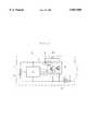
- FIG. 1is a schematic illustrative of one embodiment of the protective device according to the present invention.
- the present inventionprovides a protective device for secondary batteries having a high energy density such as lithium ion batteries using a carbonaceous material doping or dedoping lithium ions for an anode, which comprises a temperature fuse that is fused down by heat generated from a heat-generating resistance in an overcharged state at a temperature lower than the temperature at which the batteries can be used, and a discharging means actuated upon the fusing-down of the temperature fuse. After the overcharged state continues longer than the preset time, the charging process is finished to disable the battery and then place it in a dischargeable state. In the present invention, the detection of the overcharged state is not performed only by use of current or voltage.
- the protective device of the present inventionfurther comprises a current conduction cutoff means for cutting off a current when the battery voltage goes down to the final discharge voltage, and a means for detecting a voltage drop upon conduction of a current through the cutoff means to cut off the conduction of the current when the voltage drop detected exceeds the preset drop. It is thus possible to protect the secondary batteries against overcharging and an overcurrent.
- FIG. 1A preferred embodiment of the protective device according to the present invention will now be explained with reference to FIG. 1 referred to above.
- FIG. 1illustrates a protective device contained in a battery package 3 having two lithium ion batteries 1 and 2.
- Input/output terminals 4 in the protective deviceare connected at the time of charging to a constant-current and -voltage charging power source comprising a constant current-generating circuit, a constant voltage-generating circuit, a smoothing circuit and the like, and at the time of discharging to equipment with which the batteries are used.
- a controller 5includes a voltage drop-detecting means comprising a voltage-detecting means, a means for detecting the fusing-down of a temperature fuse, and a current conduction cutoff means.
- the voltage-detecting meansmonitors the voltages of the lithium ion batteries 1 and 2. When either one of the voltages exceeds a preset voltage, the voltage-detecting means is actuated to detect an overcharged state, if any, so that a current is conducted through a heat-generating resistance 7 while a transistor 6 forming a heat-generating means remains conducted.
- the heat-generating resistance 7is thermally coupled to a temperature fuse 8 provided in a charging current conduction circuit.
- the heat-generating resistancehas a heat capacity large enough to fuse down the temperature fuse for a given time, especially 10 to 30 seconds.
- the temperature fuseis used as the current cutoff means at the time of overcharging, it is possible to avoid malfunctions, e.g., current cutoffs caused as by momentarily abnormal voltages.
- malfunctionse.g., current cutoffs caused as by momentarily abnormal voltages.
- ever-greater safetyis achievable because even though a battery has anything abnormal due to overcharging, it can then be disabled to such an extent that it cannot conduct a current even by removal of an overcurrent state.
- the temperature fuseis located in the vicinity of batteries, and can be fused down at a temperature lower than the highest temperature of a separator forming a part of the batteries, at which the separator can be used.
- a separatorforming a part of the batteries
- the separatorcan be used.
- the separatoris not only softened to such a degree that it can no longer function as a separator, but also induces the reaction between active cathode and anode materials, often resulting in an internal pressure increase, thermal runaway, and so on.
- the upper limit of temperatures at which currently available polyethylene separators can be usedis about 110° C. In the practice of the present invention, therefore, it is preferable to use a temperature fuse that can be fused down at a temperature of up to 110° C.
- the active materialsare in a dischargeable state even after the supply of the charging current has been cut off.
- the amount of the active materials in the dischargeable statevaries depending on to what degree the battery is charged. However, if a battery that may have anything unusual due to overcharging, especially a lithium ion battery having a high energy density, is in a dischargeable state, a large amount of energy is then built up in the form of active materials. This may in turn lead to an intermediate likelihood of thermal runaway, an internal pressure increase, etc.
- the protective device for secondary batteries according to the present inventionis provided with a safeguard means against overcharging, which is actuated to interrupt discharge when the battery voltage-detecting means in the controller 5 detects that the voltage of either one of the batteries is lower than the final discharge voltage.
- This safeguard means against overchargingmay be made up of a switching element 11 comprising a field-effect type transistor operable to cut off the supply of a current when the detected voltage is lower than the preset value.
- the protective device for second batteries according to the present inventionis provided with a safeguard means against an overcurrent, which is actuated to cut off a current when an overcurrent flows longer than a preset time during the discharging process of the batteries.
- a switching element designed to go back to a current-conducting state upon removal of an overcurrent-providing loadmay be used in combination with a fuse that is fused down upon the conduction of a large current.
- the safeguard means against an overcurrentis designed in such a manner that a voltage drop of the current cutoff switching element is detected by an overcurrent-detecting means in the controller to cut off the current cutoff switching element, it can also be used as the switching element 11 that provides protection against overcharging. It is thus possible to dispense with two switching elements for providing protection against overcharging and an overcurrent, which must otherwise be located in a battery current-conducting circuit. This in turn makes it possible to reduce a voltage drop by the switching elements, which becomes noticeable when the current delivered from batteries to equipment with which they are used becomes large. Thus, it is possible to achieve delivery of large currents.
- the safeguard means against an overcurrentdetects that a voltage drop proportional to the current conducted exceeds a predetermined value, it puts the switching element in operation to cut off the conduction of the current, thereby providing protection to the batteries.
- this safeguard meansgoes back to the current-conducting state by removal of an overcurrent-providing load.
- the fuse designed to be fused down upon the passage of a larger overcurrentis provided, it is then possible to disable the batteries upon the passage of a larger overcurrent.
- the temperature fusewhich is fused down by the generation of heat in the heat-generating resistance in an overcharged state or an increase in battery temperature or ambient temperature at a temperature lower than the temperature at which the batteries are usable is combined with the discharging means which is actuated upon the fusing-down of the temperature fuse.
- the discharging meanswhich is actuated upon the fusing-down of the temperature fuse.
Landscapes
- Engineering & Computer Science (AREA)
- Power Engineering (AREA)
- Chemical Kinetics & Catalysis (AREA)
- General Physics & Mathematics (AREA)
- Manufacturing & Machinery (AREA)
- Chemical & Material Sciences (AREA)
- Physics & Mathematics (AREA)
- Electrochemistry (AREA)
- General Chemical & Material Sciences (AREA)
- Secondary Cells (AREA)
- Charge And Discharge Circuits For Batteries Or The Like (AREA)
- Protection Of Static Devices (AREA)
- Fuses (AREA)
- Tests Of Electric Status Of Batteries (AREA)
- Emergency Protection Circuit Devices (AREA)
Abstract
Description
Claims (4)
Applications Claiming Priority (2)
| Application Number | Priority Date | Filing Date | Title |
|---|---|---|---|
| JP8-286757 | 1996-10-29 | ||
| JP28675796AJP3248851B2 (en) | 1996-10-29 | 1996-10-29 | Battery protection device |
Publications (1)
| Publication Number | Publication Date |
|---|---|
| US5853908Atrue US5853908A (en) | 1998-12-29 |
Family
ID=17708659
Family Applications (1)
| Application Number | Title | Priority Date | Filing Date |
|---|---|---|---|
| US08/960,376Expired - LifetimeUS5853908A (en) | 1996-10-29 | 1997-10-29 | Protective device for secondary batteries |
Country Status (4)
| Country | Link |
|---|---|
| US (1) | US5853908A (en) |
| JP (1) | JP3248851B2 (en) |
| KR (1) | KR100485752B1 (en) |
| TW (1) | TW366621B (en) |
Cited By (30)
| Publication number | Priority date | Publication date | Assignee | Title |
|---|---|---|---|---|
| US6001497A (en)* | 1997-07-23 | 1999-12-14 | Nippon Moli Energy Corporation | Overcharge preventing device |
| US6038473A (en)* | 1997-04-08 | 2000-03-14 | Survivalink Corporation | Defibrillator battery with dual cell stack configuration |
| US6211650B1 (en) | 2000-01-12 | 2001-04-03 | Lockheed Martin Corporation | Battery cell by-pass circuit |
| EP1094587A1 (en)* | 1999-10-21 | 2001-04-25 | Sony International (Europe) GmbH | Mobile terminal for a wireless telecommunication system comprising a rechargeable battery and method for preventing bulging of said rechargeable battery |
| US6271646B1 (en) | 2000-07-05 | 2001-08-07 | The United States Of America As Represented By The Administrator Of The National Aeronautics And Space Administration | Battery cell by-pass circuit |
| US6275006B1 (en)* | 1998-05-27 | 2001-08-14 | Matsushita Electric Industrial Co., Ltd. | Method for charging secondary battery |
| EP1162470A1 (en)* | 2000-06-09 | 2001-12-12 | Florent Mengin | Insulation controller testing apparater for electrical networks |
| EP1229339A2 (en) | 2001-02-03 | 2002-08-07 | Microbatterie GmbH | Method of monitoring the safe operation of rechargeable lithium cells |
| EP0982826A3 (en)* | 1998-08-26 | 2003-01-02 | Sony Corporation | Battery protection circuit and electronic device |
| US20050017690A1 (en)* | 2002-07-17 | 2005-01-27 | Mathews Associates, Inc. | Battery heating circuit |
| US20070120526A1 (en)* | 2005-11-28 | 2007-05-31 | Nec Tokin Corporation | Stacked battery module and battery pack |
| CN1325924C (en)* | 2003-08-18 | 2007-07-11 | 旺宏电子股份有限公司 | Generator battery charging device monitoring circuit |
| CN100444439C (en)* | 2005-01-10 | 2008-12-17 | 惠州亿纬锂能股份有限公司 | A safe primary lithium battery |
| CN102013670A (en)* | 2010-11-10 | 2011-04-13 | 江苏双登集团有限公司 | Split type high-power lithium ion battery pack protection system |
| CN102822929A (en)* | 2010-04-08 | 2012-12-12 | 索尼化学&信息部件株式会社 | Protection element, battery control device, and battery pack |
| WO2013113473A1 (en)* | 2012-02-01 | 2013-08-08 | Daimler Ag | High-voltage battery for a vehicle and method for operating a high-voltage battery |
| CN104092190A (en)* | 2014-07-28 | 2014-10-08 | 中投仙能科技(苏州)有限公司 | Trigger type lithium battery physical protector based on equalization |
| CN104412351A (en)* | 2012-03-26 | 2015-03-11 | 迪睿合电子材料有限公司 | Protection member |
| EP2448081A3 (en)* | 2010-10-29 | 2015-03-11 | Tesla Motors, Inc. | Battery pack overcharge protection system |
| US9071069B2 (en) | 2010-04-07 | 2015-06-30 | Black & Decker Inc. | Controlled power fade for battery powered devices |
| CN108120867A (en)* | 2018-01-30 | 2018-06-05 | 天津锦泰勤业精密电子有限公司 | Overcharge test simulator and analog detecting method |
| DE102017211993A1 (en)* | 2017-07-13 | 2019-01-17 | Robert Bosch Gmbh | Driver unit, driver and diagnostic interface, battery cell, cell assembly and working device |
| DE102017211999A1 (en)* | 2017-07-13 | 2019-01-17 | Robert Bosch Gmbh | Control arrangement, cell arrangement and working device |
| DE102017211989A1 (en)* | 2017-07-13 | 2019-01-17 | Robert Bosch Gmbh | Control arrangement, cell arrangement and working device |
| US10367239B1 (en) | 2011-03-31 | 2019-07-30 | Elite Power Holdings Llc | Integral battery temperature control system |
| EP2158656B1 (en)* | 2007-05-02 | 2020-10-21 | Rosemount Inc. | Process field device with battery and overcurrent protection |
| US11063447B2 (en) | 2016-08-02 | 2021-07-13 | Samsung Sdi Co., Ltd. | Battery pack and energy storage system comprising same |
| CN113661402A (en)* | 2019-07-10 | 2021-11-16 | 株式会社Lg新能源 | Apparatus and method for detecting defects of battery pack |
| US11413935B2 (en)* | 2018-03-23 | 2022-08-16 | Hanon Systems | Coolant heater |
| CN115871462A (en)* | 2021-09-28 | 2023-03-31 | 宇通客车股份有限公司 | Excitation fusing protection method of battery system and vehicle |
Families Citing this family (20)
| Publication number | Priority date | Publication date | Assignee | Title |
|---|---|---|---|---|
| JP4608052B2 (en)* | 2000-05-16 | 2011-01-05 | 内橋エステック株式会社 | Battery protector |
| KR100889523B1 (en)* | 2002-10-25 | 2009-03-19 | 삼성에스디아이 주식회사 | Battery Pack with Thermal Fuse |
| KR101093826B1 (en) | 2004-08-30 | 2011-12-13 | 삼성에스디아이 주식회사 | Battery pack protection circuit |
| KR100601556B1 (en) | 2004-09-07 | 2006-07-19 | 삼성에스디아이 주식회사 | Secondary Battery Pack Protection Circuit |
| JP5002894B2 (en)* | 2004-12-27 | 2012-08-15 | 日産自動車株式会社 | Secondary battery |
| KR100782101B1 (en)* | 2005-04-08 | 2007-12-04 | 유니썸테크놀로지 주식회사 | Protective circuit and battery pack including same |
| KR100786937B1 (en) | 2005-07-20 | 2007-12-17 | 주식회사 엘지화학 | Apparatus for protection of secondary battery |
| JP4791995B2 (en)* | 2007-03-27 | 2011-10-12 | パナソニック株式会社 | Battery pack |
| JP4925927B2 (en)* | 2007-06-05 | 2012-05-09 | 三洋電機株式会社 | Battery pack |
| KR101213846B1 (en) | 2007-12-07 | 2012-12-18 | 현대자동차주식회사 | high voltage arc cut off fuse |
| JP2010027263A (en)* | 2008-07-16 | 2010-02-04 | Hitachi Vehicle Energy Ltd | Battery module |
| JP5319224B2 (en)* | 2008-09-25 | 2013-10-16 | 株式会社東芝 | Assembled battery system |
| JP5458647B2 (en)* | 2009-04-27 | 2014-04-02 | ミツミ電機株式会社 | Protection circuit |
| JP5053337B2 (en) | 2009-07-21 | 2012-10-17 | レノボ・シンガポール・プライベート・リミテッド | Protection element and protection system for storage battery |
| JP2012079513A (en)* | 2010-09-30 | 2012-04-19 | Gs Yuasa Corp | Abnormality history retention device |
| CN202632917U (en)* | 2010-12-31 | 2012-12-26 | 厦门赛尔特电子有限公司 | Device combining temperature fuse and resistor |
| JP7119831B2 (en)* | 2018-09-25 | 2022-08-17 | 株式会社Gsユアサ | power storage device |
| US10953726B2 (en)* | 2019-04-23 | 2021-03-23 | GM Global Technology Operations LLC | Battery thermal management |
| KR20220010963A (en) | 2020-07-20 | 2022-01-27 | 주식회사 엘지에너지솔루션 | Apparatus and method for managing battery pack |
| KR20200129084A (en) | 2020-11-10 | 2020-11-17 | 주식회사 엘지화학 | Apparatus and method for protecting MOSFET relay using a voltage detector and signal fuse |
Citations (3)
| Publication number | Priority date | Publication date | Assignee | Title |
|---|---|---|---|---|
| US5569550A (en)* | 1995-02-03 | 1996-10-29 | Motorola, Inc. | Battery pack having under-voltage and over-voltage protection |
| US5637413A (en)* | 1995-10-16 | 1997-06-10 | Motorola, Inc. | Overvoltage disconnect circuit for lithium ion batteries |
| US5645949A (en)* | 1994-09-12 | 1997-07-08 | Apple Computer, Inc. | Battery cell having an internal circuit for controlling its operation |
Family Cites Families (3)
| Publication number | Priority date | Publication date | Assignee | Title |
|---|---|---|---|---|
| JP2605944Y2 (en)* | 1993-01-12 | 2000-09-04 | 三洋電機株式会社 | Battery charging system |
| JP3121963B2 (en)* | 1993-06-30 | 2001-01-09 | 太陽誘電株式会社 | battery pack |
| JP3338564B2 (en)* | 1994-09-28 | 2002-10-28 | 富士通株式会社 | Battery pack and device using battery pack |
- 1996
- 1996-10-29JPJP28675796Apatent/JP3248851B2/ennot_activeExpired - Lifetime
- 1997
- 1997-10-07TWTW086114617Apatent/TW366621B/ennot_activeIP Right Cessation
- 1997-10-23KRKR1019970054301Apatent/KR100485752B1/ennot_activeExpired - Lifetime
- 1997-10-29USUS08/960,376patent/US5853908A/ennot_activeExpired - Lifetime
Patent Citations (3)
| Publication number | Priority date | Publication date | Assignee | Title |
|---|---|---|---|---|
| US5645949A (en)* | 1994-09-12 | 1997-07-08 | Apple Computer, Inc. | Battery cell having an internal circuit for controlling its operation |
| US5569550A (en)* | 1995-02-03 | 1996-10-29 | Motorola, Inc. | Battery pack having under-voltage and over-voltage protection |
| US5637413A (en)* | 1995-10-16 | 1997-06-10 | Motorola, Inc. | Overvoltage disconnect circuit for lithium ion batteries |
Cited By (43)
| Publication number | Priority date | Publication date | Assignee | Title |
|---|---|---|---|---|
| US6038473A (en)* | 1997-04-08 | 2000-03-14 | Survivalink Corporation | Defibrillator battery with dual cell stack configuration |
| US6001497A (en)* | 1997-07-23 | 1999-12-14 | Nippon Moli Energy Corporation | Overcharge preventing device |
| US6275006B1 (en)* | 1998-05-27 | 2001-08-14 | Matsushita Electric Industrial Co., Ltd. | Method for charging secondary battery |
| USRE40223E1 (en)* | 1998-05-27 | 2008-04-08 | Matsushita Electric Industrial Co., Ltd. | Method for charging secondary battery |
| EP0982826A3 (en)* | 1998-08-26 | 2003-01-02 | Sony Corporation | Battery protection circuit and electronic device |
| EP1094587A1 (en)* | 1999-10-21 | 2001-04-25 | Sony International (Europe) GmbH | Mobile terminal for a wireless telecommunication system comprising a rechargeable battery and method for preventing bulging of said rechargeable battery |
| US6211650B1 (en) | 2000-01-12 | 2001-04-03 | Lockheed Martin Corporation | Battery cell by-pass circuit |
| EP1162470A1 (en)* | 2000-06-09 | 2001-12-12 | Florent Mengin | Insulation controller testing apparater for electrical networks |
| FR2810115A1 (en)* | 2000-06-09 | 2001-12-14 | Florent Raymond Andre Mengin | APPARATUS FOR TESTING INSULATION CONTROLLERS OF ELECTRICAL NETWORKS |
| US6271646B1 (en) | 2000-07-05 | 2001-08-07 | The United States Of America As Represented By The Administrator Of The National Aeronautics And Space Administration | Battery cell by-pass circuit |
| EP1229339A2 (en) | 2001-02-03 | 2002-08-07 | Microbatterie GmbH | Method of monitoring the safe operation of rechargeable lithium cells |
| EP1229339B1 (en)* | 2001-02-03 | 2010-12-01 | VARTA Microbattery GmbH | Method of monitoring the safe operation of rechargeable lithium cells |
| US20050017690A1 (en)* | 2002-07-17 | 2005-01-27 | Mathews Associates, Inc. | Battery heating circuit |
| US7327122B2 (en)* | 2002-07-17 | 2008-02-05 | Mathews Associates, Inc. | Battery heating circuit |
| CN1325924C (en)* | 2003-08-18 | 2007-07-11 | 旺宏电子股份有限公司 | Generator battery charging device monitoring circuit |
| CN100444439C (en)* | 2005-01-10 | 2008-12-17 | 惠州亿纬锂能股份有限公司 | A safe primary lithium battery |
| US8049463B2 (en)* | 2005-11-28 | 2011-11-01 | Nec Energy Devices, Ltd. | Stacked battery module and battery pack |
| US20070120526A1 (en)* | 2005-11-28 | 2007-05-31 | Nec Tokin Corporation | Stacked battery module and battery pack |
| EP2158656B1 (en)* | 2007-05-02 | 2020-10-21 | Rosemount Inc. | Process field device with battery and overcurrent protection |
| US9692157B2 (en) | 2010-04-07 | 2017-06-27 | Black & Decker Inc. | Controlled power fade for battery power devices |
| US9071069B2 (en) | 2010-04-07 | 2015-06-30 | Black & Decker Inc. | Controlled power fade for battery powered devices |
| US9413088B2 (en) | 2010-04-07 | 2016-08-09 | Black & Decker Inc. | Controlled power fade for battery powered devices |
| CN102822929A (en)* | 2010-04-08 | 2012-12-12 | 索尼化学&信息部件株式会社 | Protection element, battery control device, and battery pack |
| CN102822929B (en)* | 2010-04-08 | 2015-09-23 | 迪睿合电子材料有限公司 | Protection component, battery control device and battery pack |
| EP2448081A3 (en)* | 2010-10-29 | 2015-03-11 | Tesla Motors, Inc. | Battery pack overcharge protection system |
| CN102013670A (en)* | 2010-11-10 | 2011-04-13 | 江苏双登集团有限公司 | Split type high-power lithium ion battery pack protection system |
| US10367239B1 (en) | 2011-03-31 | 2019-07-30 | Elite Power Holdings Llc | Integral battery temperature control system |
| WO2013113473A1 (en)* | 2012-02-01 | 2013-08-08 | Daimler Ag | High-voltage battery for a vehicle and method for operating a high-voltage battery |
| CN104412351A (en)* | 2012-03-26 | 2015-03-11 | 迪睿合电子材料有限公司 | Protection member |
| CN104412351B (en)* | 2012-03-26 | 2017-06-09 | 迪睿合电子材料有限公司 | Protection element |
| CN104092190A (en)* | 2014-07-28 | 2014-10-08 | 中投仙能科技(苏州)有限公司 | Trigger type lithium battery physical protector based on equalization |
| US11063447B2 (en) | 2016-08-02 | 2021-07-13 | Samsung Sdi Co., Ltd. | Battery pack and energy storage system comprising same |
| DE102017211999A1 (en)* | 2017-07-13 | 2019-01-17 | Robert Bosch Gmbh | Control arrangement, cell arrangement and working device |
| DE102017211989A1 (en)* | 2017-07-13 | 2019-01-17 | Robert Bosch Gmbh | Control arrangement, cell arrangement and working device |
| DE102017211993A1 (en)* | 2017-07-13 | 2019-01-17 | Robert Bosch Gmbh | Driver unit, driver and diagnostic interface, battery cell, cell assembly and working device |
| CN108120867A (en)* | 2018-01-30 | 2018-06-05 | 天津锦泰勤业精密电子有限公司 | Overcharge test simulator and analog detecting method |
| CN108120867B (en)* | 2018-01-30 | 2023-08-25 | 浙江锦泰电子有限公司 | Overcharge detection simulation device and simulation detection method |
| US11413935B2 (en)* | 2018-03-23 | 2022-08-16 | Hanon Systems | Coolant heater |
| CN113661402A (en)* | 2019-07-10 | 2021-11-16 | 株式会社Lg新能源 | Apparatus and method for detecting defects of battery pack |
| EP3982142A4 (en)* | 2019-07-10 | 2022-08-17 | LG Energy Solution, Ltd. | Apparatus and method for detecting defect in battery pack |
| CN113661402B (en)* | 2019-07-10 | 2023-08-25 | 株式会社Lg新能源 | Apparatus and method for detecting defect of battery pack |
| US11828812B2 (en) | 2019-07-10 | 2023-11-28 | Lg Energy Solution, Ltd. | Apparatus and method for detecting defect of battery pack |
| CN115871462A (en)* | 2021-09-28 | 2023-03-31 | 宇通客车股份有限公司 | Excitation fusing protection method of battery system and vehicle |
Also Published As
| Publication number | Publication date |
|---|---|
| KR19980033071A (en) | 1998-07-25 |
| TW366621B (en) | 1999-08-11 |
| JP3248851B2 (en) | 2002-01-21 |
| KR100485752B1 (en) | 2005-08-10 |
| JPH10136581A (en) | 1998-05-22 |
Similar Documents
| Publication | Publication Date | Title |
|---|---|---|
| US5853908A (en) | Protective device for secondary batteries | |
| US6060185A (en) | Protective device for secondary batteries | |
| US6531846B1 (en) | Final discharge of a cell activated by a circuit that senses when a charging fault has occurred | |
| US9130383B2 (en) | Charging/discharging control device, battery pack, electrical equipment, and charging/discharging control method | |
| US7898216B2 (en) | Rechargeable battery device having a protection circuit for protecting from overcharge and overdischarge | |
| JP5209122B2 (en) | Apparatus and method for protecting battery pack by sensing destruction of sense resistor | |
| JP4659886B2 (en) | Secondary battery protection circuit | |
| US8179097B2 (en) | Protection circuit for battery pack and battery pack having the same | |
| EP1787339A4 (en) | OVERLOADING SAFETY DEVICE AND ACCUMULATOR USING THE SAME | |
| KR20080067948A (en) | Hybrid battery and method for charging and discharging it | |
| US6001497A (en) | Overcharge preventing device | |
| US20160094068A1 (en) | Secondary battery protection circuit and battery device | |
| JPH0919053A (en) | Battery protection device | |
| JP3620796B2 (en) | Battery pack | |
| JP3676935B2 (en) | Battery pack | |
| JP2004146307A (en) | Battery unit | |
| JP2009100605A (en) | Protection circuit and battery pack | |
| KR101603626B1 (en) | Protective circuit for preventing overcharge | |
| KR102176943B1 (en) | Battery Pack | |
| KR20170025805A (en) | Battery cell protection circuit | |
| JP3538175B2 (en) | Battery protection device | |
| KR102137698B1 (en) | Protection circuit device for battery | |
| JP2003153435A (en) | Secondary battery protection circuit | |
| JP2002191130A (en) | Reverse-charge preventing circuit | |
| KR20130090159A (en) | Protective circuit for preventing overcharge |
Legal Events
| Date | Code | Title | Description |
|---|---|---|---|
| AS | Assignment | Owner name:NIPPON MOLI ENERGY CORP., JAPAN Free format text:ASSIGNMENT OF ASSIGNORS INTEREST;ASSIGNOR:OKUTOH, TADASHI;REEL/FRAME:008868/0537 Effective date:19971003 | |
| STCF | Information on status: patent grant | Free format text:PATENTED CASE | |
| AS | Assignment | Owner name:NEC MOBILE ENERGY CORP., JAPAN Free format text:CHANGE OF NAME AND CHANGE OF ADDRESS;ASSIGNOR:OKUTOH, TADASHI;REEL/FRAME:010685/0547 Effective date:19971003 | |
| FEPP | Fee payment procedure | Free format text:PAT HOLDER CLAIMS SMALL ENTITY STATUS, ENTITY STATUS SET TO SMALL (ORIGINAL EVENT CODE: LTOS); ENTITY STATUS OF PATENT OWNER: LARGE ENTITY | |
| FPAY | Fee payment | Year of fee payment:4 | |
| SULP | Surcharge for late payment | ||
| REMI | Maintenance fee reminder mailed | ||
| AS | Assignment | Owner name:NEC TOKIN TOCHIGI, LTD., JAPAN Free format text:ASSIGNMENT OF ASSIGNORS INTEREST;ASSIGNOR:NEC MOBILE ENERGY CORP.;REEL/FRAME:013117/0789 Effective date:20020712 | |
| FEPP | Fee payment procedure | Free format text:PAYOR NUMBER ASSIGNED (ORIGINAL EVENT CODE: ASPN); ENTITY STATUS OF PATENT OWNER: LARGE ENTITY | |
| FEPP | Fee payment procedure | Free format text:PAT HOLDER NO LONGER CLAIMS SMALL ENTITY STATUS, ENTITY STATUS SET TO UNDISCOUNTED (ORIGINAL EVENT CODE: STOL); ENTITY STATUS OF PATENT OWNER: LARGE ENTITY | |
| REFU | Refund | Free format text:REFUND - PAYMENT OF MAINTENANCE FEE, 8TH YR, SMALL ENTITY (ORIGINAL EVENT CODE: R2552); ENTITY STATUS OF PATENT OWNER: LARGE ENTITY | |
| FPAY | Fee payment | Year of fee payment:8 | |
| FPAY | Fee payment | Year of fee payment:12 | |
| AS | Assignment | Owner name:NEC ENERGY DEVICES, LTD., JAPAN Free format text:ASSIGNMENT OF ASSIGNORS INTEREST;ASSIGNOR:NEC TOKIN CORPORATION;REEL/FRAME:025041/0001 Effective date:20100713 |