US5853386A - Infusion device with disposable elements - Google Patents
Infusion device with disposable elementsDownload PDFInfo
- Publication number
- US5853386A US5853386AUS08/686,757US68675796AUS5853386AUS 5853386 AUS5853386 AUS 5853386AUS 68675796 AUS68675796 AUS 68675796AUS 5853386 AUS5853386 AUS 5853386A
- Authority
- US
- United States
- Prior art keywords
- fluid
- pump
- delivery conduit
- pumping
- patient
- Prior art date
- Legal status (The legal status is an assumption and is not a legal conclusion. Google has not performed a legal analysis and makes no representation as to the accuracy of the status listed.)
- Expired - Lifetime
Links
Images


Classifications
- A—HUMAN NECESSITIES
- A61—MEDICAL OR VETERINARY SCIENCE; HYGIENE
- A61M—DEVICES FOR INTRODUCING MEDIA INTO, OR ONTO, THE BODY; DEVICES FOR TRANSDUCING BODY MEDIA OR FOR TAKING MEDIA FROM THE BODY; DEVICES FOR PRODUCING OR ENDING SLEEP OR STUPOR
- A61M5/00—Devices for bringing media into the body in a subcutaneous, intra-vascular or intramuscular way; Accessories therefor, e.g. filling or cleaning devices, arm-rests
- A61M5/36—Devices for bringing media into the body in a subcutaneous, intra-vascular or intramuscular way; Accessories therefor, e.g. filling or cleaning devices, arm-rests with means for eliminating or preventing injection or infusion of air into body
- A61M5/365—Air detectors
- A—HUMAN NECESSITIES
- A61—MEDICAL OR VETERINARY SCIENCE; HYGIENE
- A61M—DEVICES FOR INTRODUCING MEDIA INTO, OR ONTO, THE BODY; DEVICES FOR TRANSDUCING BODY MEDIA OR FOR TAKING MEDIA FROM THE BODY; DEVICES FOR PRODUCING OR ENDING SLEEP OR STUPOR
- A61M5/00—Devices for bringing media into the body in a subcutaneous, intra-vascular or intramuscular way; Accessories therefor, e.g. filling or cleaning devices, arm-rests
- A61M5/14—Infusion devices, e.g. infusing by gravity; Blood infusion; Accessories therefor
- A61M5/168—Means for controlling media flow to the body or for metering media to the body, e.g. drip meters, counters ; Monitoring media flow to the body
- A61M5/16831—Monitoring, detecting, signalling or eliminating infusion flow anomalies
- A61M5/16854—Monitoring, detecting, signalling or eliminating infusion flow anomalies by monitoring line pressure
- A—HUMAN NECESSITIES
- A61—MEDICAL OR VETERINARY SCIENCE; HYGIENE
- A61M—DEVICES FOR INTRODUCING MEDIA INTO, OR ONTO, THE BODY; DEVICES FOR TRANSDUCING BODY MEDIA OR FOR TAKING MEDIA FROM THE BODY; DEVICES FOR PRODUCING OR ENDING SLEEP OR STUPOR
- A61M2205/00—General characteristics of the apparatus
- A61M2205/12—General characteristics of the apparatus with interchangeable cassettes forming partially or totally the fluid circuit
- A—HUMAN NECESSITIES
- A61—MEDICAL OR VETERINARY SCIENCE; HYGIENE
- A61M—DEVICES FOR INTRODUCING MEDIA INTO, OR ONTO, THE BODY; DEVICES FOR TRANSDUCING BODY MEDIA OR FOR TAKING MEDIA FROM THE BODY; DEVICES FOR PRODUCING OR ENDING SLEEP OR STUPOR
- A61M2205/00—General characteristics of the apparatus
- A61M2205/33—Controlling, regulating or measuring
- A61M2205/3306—Optical measuring means
- Y—GENERAL TAGGING OF NEW TECHNOLOGICAL DEVELOPMENTS; GENERAL TAGGING OF CROSS-SECTIONAL TECHNOLOGIES SPANNING OVER SEVERAL SECTIONS OF THE IPC; TECHNICAL SUBJECTS COVERED BY FORMER USPC CROSS-REFERENCE ART COLLECTIONS [XRACs] AND DIGESTS
- Y10—TECHNICAL SUBJECTS COVERED BY FORMER USPC
- Y10S—TECHNICAL SUBJECTS COVERED BY FORMER USPC CROSS-REFERENCE ART COLLECTIONS [XRACs] AND DIGESTS
- Y10S128/00—Surgery
- Y10S128/13—Infusion monitoring
Definitions
- This inventionrelates generally to a medication infusion device for administering fluid to patients and more particularly to an improved, ambulatory infusion device with a disposable administration set which is inexpensive to manufacture, convenient to operate and which ensures fluid delivery at a consistent and uniform rate. More specifically, this invention relates to an occlusion detection system for sensing a blockage in either a supply tube which provides medication to such an ambulatory infusion device or an outlet tube which provides medication from such an infusion device to a patient.
- medication dispensers and infusion devicesare used for infusion of predetermined amounts of medication into the body of a patient.
- Various types of medication dispensers employing different techniques for a variety of applicationsare known to exist.
- disposable equipment for medical applicationsis desirable so as to maintain a germ-free environment to prevent the transfer of infection especially where cost prohibits cleaning and sterilization after each use.
- Disposable elementsespecially in an ambulatory infusion environment, must be low in cost, since clinical application of disposable administration sets requires that the administration sets be regularly replaced. Typically, such sets are replaced every 24 to 48 hours, and seldom remain in use longer than one week. This frequent replacement interval should ideally be fulfilled by an inexpensively molded, disposable, mechanism which would normally not last the years of service life expected from the pump itself.
- an occlusion detection systemmust be able to reliably operate with such disposable administration sets.
- occlusion sensorshave typically mechanically sensed the tubing of the administration set. Thus, such systems required a highly precise, repeatable positioning of the occlusion sensor against each new administration set. This requirement subjected prior art sensors to frequent failure and maintenance problems.
- Some prior art devicesincorporate a pressure transducer and diaphragm assembly to monitor fluid pressure as an indication of occlusion. Such an occlusion detection technique is undesirable in view of the complexities and cost involved.
- strain gagesto measure the diameter of the supply tube as a means of sensing occlusions. For example, it is known to sense the diameter of a supply tube with a strain gage to detect upstream or supply occlusions. Thus, upon the occurrence of an occlusions in the supply tube, or an empty supply bag or vessel, a vacuum will be drawn in the supply tube by the continued operation of the pump. Because the supply tube is formed of resilient material, this vacuum will slightly reduce the diameter of the tube. A strain gage mounted against the outside wall of the tube senses the diameter reduction, and activates an occlusion alarm. Repeatedly placing the disposable tubing accurately against such a strain gage is difficult and makes such systems less reliable than would be desirable.
- the present inventionis an improved occlusion sensing system for an ambulatory infusion device having a disposable administration set.
- the occlusion sensoris relatively insensitive to mechanical misalignment of the disposable administration set in the pump, is inexpensive to manufacture and provides reliable, consistent protection from both upstream (supply) and downstream (patient output) occlusions.
- the present inventionutilizes two pumping cams and two pumping cam followers, which function such that, at any point in time, one of the two pumping cams is always pumping.
- the two pumping camscomprise a primary pumping cam associated with an upstream segment of the delivery tube and a secondary pumping cam associated with a downstream segment of the delivery tube.
- the primary pumping camis wider than the secondary pumping cam, so that it can displace sufficient fluid during its pumping stroke to deliver fluid external to the pump and at the same time deliver fluid to the section of the tubing beneath the secondary pumping cam to allow it to fill.
- the secondary pumping camis narrower, since it only needs to deliver fluid external to the pump.
- the present inventionadditionally utilizes pinching cams and pinching cam followers, which open and close the delivery tube to allow the pumping action to function properly.
- the pinching camscomprise an inlet pinching cam associated with the upstream segment of the tube and an outlet pinching cam associated with the downstream segment of the tube.
- the pumping cam followersacted upon by the pumping cams, control the rate of fluid flow, while the pinching cam followers acted upon by the pinching cams, operate as valves for the pump.
- Such a configurationallows one segment of the delivery tube to fill with fluid while another segment of the delivery tube is pumping, thus providing a continuous and uniform fluid flow.
- the disposable administration set of the infusion deviceis less prone to operator loading errors. This is accomplished through a reduced number of required operations and a reduction in the complexity of the operations. This is facilitated by providing channels extending along the length of the walls of a housing structure of the infusion device. These channels slidingly receive the disposable administration set in a simple, single insertion step. Additionally, since the disposable administration set includes the delivery tube retainer plate and cam followers, the position of the delivery tube relative to the tubing retainer plate and cam followers is established in a manufacturing operation which can be closely controlled. Assemblers are not under the stress of a clinical situation and they specialize in the proper assembly of the disposable administration set. Good manufacturing procedures provide additional checking systems to insure that the tubing is properly loaded and that the administration set properly assembled. These practices are not possible in a clinical environment.
- the set loading and retaining channelsallow precise positioning of the tubing, followers, and pressure plate without any adjustments or complicated, bulky, or expensive mechanisms.
- the disposable administration setresults in an overall fluid delivery system which is small, lightweight, and ambulatory.
- the disposable administration setincludes a channel segment which is slightly narrower than the outside diameter of the tubing. Consequently, when the tubing is positioned within this channel at the time of manufacture, a narrow portion of the tube wall will be flattened against the wall of the channel of the administration set: This narrow portion forms a contact line with the channel wall having a highly predictable line width.
- a source of illuminationis directed at the channel wall, and a photodetector is used to measure the width of this contact line. If pressure within the tube causes the tube's diameter to increase, the contact line width will increase. Likewise, if a vacuum is drawn within the tube, so that the diameter of the tube decreases, the contact line width will decrease. In fact, the contact line may disappear altogether if contact between the channel wall and the tube ceases.
- This channel segmentis placed between the two pinching cam follower locations in the pump.
- the tubing in this channel segmentis subjected to the output pressure of the pump.
- the downstream pinching campinches the downstream follower against the delivery tube, and the upstream pinching cam follower is raised away from the tube, the tubing in this channel segment is subjected to the inlet pressure or vacuum of the pump.
- a light sourcesuch as a light emitting diode (LED) is positioned on the outside of the channel wall at the channel segment.
- the channel wallis transparent, and the light from the LED thus illuminates the region of contact between the tubing and the channel segment wall. If the light is introduced at an angle relative to the plane of the channel segment wall, total internal reflection will occur at the channel segment wall when the tubing does not contact the wall, i.e., when the difference between the index of refraction of the channel wall and surrounding air is relatively high.
- the tubingcontacts the channel wall, because the tubing has a higher index of refraction than air, the difference between the refractive indexes of the wall and the tubing is such as to prohibit total internal reflection at the channel wall.
- a photodetectoris placed at the channel wall, and directed toward the contact line. When total internal reflection occurs, the detector is illuminated. When no total internal reflection occurs, the detector is not illuminated. As the contact line width increases, the degree of total internal reflection is altered, and the amount of light at the photodetector changes. By measuring the output from the photodetector, the pumping system can determine the extent of pressure or vacuum in the tube at the channel segment.
- an upstream occlusion alarmis activated.
- the output of the photodetectordecreases, indicating decreased total internal reflection caused by a widening of the contact line due to pressure in the tubing, a downstream occlusion alarm is activated.
- This occlusion sensing systemis simple, rugged, reliable and inexpensive. It permits a single sensor to measure both upstream and downstream occlusions, without requiring precise alignment of the administration set within the pump.
- FIG. 1is a perspective, exploded view illustrating an infusion device having a disposable administration set in accordance with the present invention.
- FIG. 2is a perspective view illustrating a disposable administration set for use with the infusion device of FIG. 1.
- FIG. 3is a cross section view taken along the line 3--3 of FIG. 1.
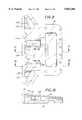
- FIG. 4is a plan view illustrating the single-piece cam of the invention.
- FIG. 4ais a cross section view taken along the line a--a of FIG. 4 illustrating the contour of the outlet or secondary or downstream pumping cam of the present invention.
- FIG. 4bis a cross section view taken along the line b--b of FIG. 4 illustrating the contour of the outlet pinching cam of the present invention.
- FIG. 4cis a cross section view taken along the line c--c of FIG. 4 illustrating the contour of the inlet or primary or upstream pumping cam of the present invention.
- FIG. 4dis a cross section view taken along the line d--d of the present invention illustrating the contour of the inlet pinching cam of the present invention.
- FIG. 5is a plan view illustrating a cam follower and spacer assembly of the present invention.
- FIG. 6is a side elevation exploded view illustrating the cam follower and spacer assembly and the plate assembly.
- FIG. 7is a graphical representation of the cam radii versus the angle of cam rotation of the present invention.
- FIG. 8is a graphical representation of the tubing ID gap versus the angle of cam rotation of the present invention.
- FIG. 9is a plan view of an the tubing retainer plate of the administration set of this invention, showing the optical path elements for the occlusion detection system.
- FIG. 10is a sectional view of the tubing retainer plate of FIG. 9, taken along line 10--10 of FIG. 9, along with a broken away portion of the infusion device body, showing the positional relationship of the retainer plate when the administration set is installed in the infusion device.
- FIG. 11is a sectional view of the tubing retainer plate of FIG. 9, taken along line 11--11 of FIG. 9, showing the positional relationship of the tubing and the retainer plate when the administration set is installed in the infusion device, and neither the inlet nor the outlet tubing is occluded.
- FIG. 12is a sectional view of the tubing retainer plate of FIG. 9, taken along line 11--11 of FIG. 9, identical to FIG. 11, but showing the positional relationship of the tubing and the retainer plate when the administration set is installed in the infusion device and the inlet tubing is occluded.
- FIG. 13is a sectional view of the tubing retainer plate of FIG. 9, taken along line 11--11 of FIG. 9, identical to FIGS. 11 and 12, but showing the positional relationship of the tubing and the retainer plate when the administration set is installed in the infusion device and the outlet tubing is occluded.
- FIG. 14is a sectional view of the tubing retainer plate of FIG. 9, taken along line 14--14 of FIG. 9, along with a broken away portion of the infusion device body and the adjacent wall of the tubing, showing the positional relationship of the retainer plate and the occlusion sensors when the administration set is installed in the infusion device.
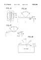
- FIG. 15is a broken-away schematic view showing the view of the tubing retainer plate at the photosensor of the occlusion sensing system.
- FIG. 16is a schematic view, similar to the view of FIG. 14, illustrating the light path when there is no occlusion, or when there is a downstream occlusion.
- FIG. 17is a schematic view, identical to FIG. 16, except that it illustrates the light path when there is an upstream occlusion.
- FIG. 18is a schematic view, identical to FIG. 16, except that it illustrates the light path when there is a bubble in the fluid in the tubing.
- FIG. 19is a schematic view, identical to FIG. 16, except that it illustrates the light path when there is a downstream occlusion and a fluid leak in the system.
- FIG. 1illustrates the infusion device 10 of the present invention for administering intravenous fluid at a consistent and uniform rate.
- the infusion device 10is designed to be small, lightweight and ambulatory.
- the infusion device 10includes a disposable administration set 12 having a plurality of cam followers 42 which are displaced in a predetermined sequence when depressed by a pumping mechanism 64 to squeeze a delivery tube 36 for dispensing fluid.
- a simplified administration set 12without provision for the occlusion sensor of the present invention, is shown, and will be used to explain the operation of the device 10 by way of background.
- the pumping mechanism 64is driven by a commercially available motor 11 (not shown).
- the disposable administration set 12loads easily into the housing structure 66 adjacent the pumping mechanism 64.
- an optional fluid reservoir 60which provides a continuous flow of fluid to the inlet of the delivery tube 36 for dispensing and infusing fluid into a patient's body.
- the fluid delivery tube 36may connect to an external reservoir (not shown), or the reservoir 60 may be located at other positions on the assembly.
- the housing structure 66comprises a rectangular chamber 67 surrounded by side walls 68 and a rear wall 69.
- the floor of the rectangular chamber 67drops into a recess 70 towards the front end.
- the pumping mechanism 64is located within the recess 70.
- Extending throughout the length and parallel to the base of each of the side walls 68is a narrow channel 72 having a lower shoulder 73.
- the disposable administration set 12slides within the channels 72.
- each of the channels 72includes a spring-biased ball assembly 75.
- the disposable administration set 12while being manually inserted into the channels 72, depresses the spring assemblies 75. After insertion of the set 12, the spring assemblies on either side bias the disposable administration set 12 against the shoulders 73 of the channels 72, holding the disposable administration set 12 accurately in position.
- the disposable administration set 12is manually loaded into the infusion device 10 in a simple sliding operation. As the administration set 12 slides into the infusion device, the cam followers 42 are gradually pushed against the delivery tube 36 by the pumping mechanism 64.
- FIGS. 2 and 6illustrate the simplified disposable administration set 12 without the occlusion sensing of the present invention.
- the disposable administration set 12is formed from rigid transparent plastic or the like, and includes a tubing retainer plate assembly 14 which may advantageously be injection molded as a single piece.
- the tubing retainer plate assembly 14includes a tubing retainer plate 16 having a flat tube-contacting surface and a cam follower retainer 20 projecting normal to this surface at one end.
- the cam follower retainer 20terminates in a an overhanging latch 24 projecting substantially parallel to the retainer plate 16.
- the latch 24serves as a locking mechanism for holding the cam followers 42 in position, adjacent the tube 36 prior to insertion of the administration set 12 into the housing 66.
- some of the cam followers 42are depressed by the pumping mechanism 64.
- the followersreturn to a standby position against the latch 24.
- the disposable administration set 12further includes a cam follower and spacer assembly 40.
- the cam follower and spacer assembly 40may also be injection molded as a single piece independent of the tubing retainer plate 16.
- the cam follower and spacer assembly 40may be molded as one piece with the tubing retainer plate assembly 14 provided that a hinge is molded to connect the cam follower and spacer assembly 40 to the tubing retainer plate assembly 14.
- the cam follower and spacer assembly 40includes two gap correction spacers 44 in the form of elongated extending finger-like projections which flank the tubing retainer plate 16 on either side (as best seen in FIG. 2).
- the thickness of the cam followers 42is a critical dimension which directly effects the volume of the delivery tube 36.
- the accurate pinching of the delivery tube 36is necessary to allow a desired flow of fluid through the available passage.
- the gap correction spacers 44advantageously counteract these thickness variations.
- the thickness of both the cam followers 42 and the gap spacers 44will vary by the same amount, because they are formed in the same mold cavity. Thus, any molding variations, such as those due to mold temperature or pressure, will affect both of these parts identically.
- the dispensing tube 36is positioned immediately below the spring-biased retainer 75.
- the spring-biased retainer 75holds the administration set accurately in place against the shoulders 73 (as best seen in FIG. 1) as described earlier.
- the cam followers 42are pushed against the tube 36 by a plurality of cams 85, one of which is shown in FIG. 3. Pumping is accomplished, as will be described below, by squeezing the tube 36.
- the gap correction spacer 44rests between the plate 16 and the shoulder 73 (as best seen in FIG. 1). Thus, if the spacer 44 is thicker than normal, the plate 16 will be positioned further from the cam 85 than normal. However, in this case, as explained above, the cam followers 42 will also be thicker than normal, offsetting the effect of the thicker spacer 44. It is advantageous, in accomplishing this self correction, that the thickness of the spacer 44 be the same as that of the active part of the follower 42, so that they will vary identically in thickness.
- the plurality of cam followers 42includes an inlet pincher cam follower 43, a primary, upstream, inlet pumping cam follower 46, an outlet pincher cam follower 48, and a secondary, downstream, outlet pumping cam follower 50.
- Each of the cam followers 42are attached to the cam follower and spacer assembly 40 by flexible cam follower arms 54.
- Each of the cam followers 42are displaced toward the delivery tube 36 in a predetermined sequence.
- the inlet pincher cam follower 43 and the outlet pincher cam follower 48deform the fluid delivery tube 36 to close it off, and thus act as valves.
- the primary pumping cam follower 46 and the secondary pumping cam follower 50pump the fluid through the delivery tube 36.
- the primary pumping cam follower 46 which contacts the upstream segment of the delivery tube 36is approximately twice the width of the secondary pumping cam follower 50, and it thus squeezes twice the length of tubing. This facilitates displacement of enough fluid during a pumping stroke for delivering fluid external to the pump and at the same time delivering fluid to the downstream segment of the fluid delivery tube 36, beneath the follower 50, to allow it to fill.
- the follower 46is being advanced toward the tube 36, the follower 50 is being withdrawn.
- the fluid displaced by the follower 46fills the tube 36 as it is released by the follower 50, and also supplies enough fluid to continue the outflow from the pump.
- the pumping mechanism 64which provides a continuous and uniform flow will be described.
- the pumping mechanism 64comprises a cam assembly 84 and an axle shaft 86.
- the cam assembly 84is preferably formed and machined from a single piece of metal.
- the cam assembly 84may be cast, and later machined.
- the assembly 84includes a central aperture 83 to accommodate an axle shaft 86.
- the shaft 86may include a flat 86a to couple the shaft 86 to a motor.
- the axle shaft 86rotates within bearings which are in turn mounted in two apertures formed within the walls 68 as best seen in FIG. 1.
- the axle shaft 86 driven by the motorprovides rotation to the cam assembly 84.
- the cam followers 42are displaced in a predetermined sequence, as described below, thereby squeezing the delivery tube 36 and dispensing a specified volume of fluid.
- the cam assembly 84is specifically designed such that each incremental angle of revolution displaces the same amount of fluid.
- the cam assembly 84includes the plurality of spaced cams 85.
- the plurality of spaced cams 85include an inlet pincher cam 87, a primary, upstream, inlet pumping cam 88, an outlet pincher cam 90 and a secondary, downstream, outlet pumping cam 92.
- the inlet pincher cam 87 and the primary pumping cam 88are operably associated with the inlet pincher cam follower 43 and the primary pumping cam follower 46, respectively.
- the outlet pincher cam 90 and the secondary pumping cam 92are likewise operably associated with the outlet pincher cam follower 48 and the secondary pumping cam follower 50.
- the inlet pincher cam 87 and the outlet pincher cam 90operate as valves for the pumping action.
- the surfaces of the pincher cams 87, 90are contoured such that between specified rotational positions either the upstream or the downstream segment of the tube 36 is pinched off to obstruct fluid flow.
- the primary pumping cam 88 and the secondary pumping cam 92include active pumping surfaces which are uniquely contoured so that the fluid delivery tube 36 is squeezed in such a manner that a constant speed of rotation of the axle shaft 86 results in a uniform or constant displacement of fluid volume from the appropriate segment of the fluid delivery tube 36.
- the primary pumping cam 88 and the secondary pumping cam 92 surfacesare contoured based upon the following principles and calculations.
- An incremental part of the cam rotationis selected for filling and the remaining part of the rotation will be for pumping. For example, if 180° is selected for pumping, then each incremental area change will occur in 1.8° increments such that the g for the first incremental area will occur at 1.8 degrees, the g for the second incremental area will occur at 3.6 degrees, etc. Finally, the g for the 100th area will occur at 180 degrees.
- the cam radiuses at each incrementcan then be calculated by subtracting the required g value from the displacement between the center of the cam to the face of the plate assembly minus the cam follower thickness minus 2 times the tubing wall thickness plus the gap spacer thickness.
- the relationship between the cam radius and the tubing gapis algebraically proportional only when the cam radius in constant.
- the effect of the approximately horizontal surface of the follower, contacting the changing cam surfacemakes it necessary to take the phase and amplitude into consideration.
- a rapidly increasing cam surfaceresults in a gap change that leads the actual radius change.
- a rapidly decreasing cam radiusresults in a gap change that lags the actual radius change.
- the amount of change in phaseis a function of a ratio of the beginning and ending cam radii.
- the present inventionutilizes approximate predicted phase changes based on calculations, of the ratio of the beginning and ending cam radii, relative to the rotational positions of the cam. This effect is more significant in the case of the rapidly changing pincher cams which are characterized by transitioning phase changes of approximately 35 degrees.
- the actual gapsare numerically computed as described.
- each radiushas a vertical component which is computed by multiplying the actual radius length by the cosine of the angle that is formed by that radius relative to a vertical line.
- the vertical linepasses through the center of the axle shaft and is approximately normal to the surface of the cam follower. The vertical component of each radius thus changes as the cam rotates about its axis.
- the cam followerSince the follower is formed to contact the cam surface in an approximately downward direction, for a particular degree of rotation of the cam, the cam follower will contact the cam surface at the radius which has the greatest positive vertical component.
- the actual radius of contact at each degree of rotationis determined by numerically computing the radius with the greatest vertical component at each degree of rotation.
- the cam assembly 84rotates about the axle shaft 86 and acts through the cam followers upon the delivery tube 36 positioned directly beneath the cam assembly 84.
- the inlet pincher cam 87As best seen in FIG. 7, between the rotational positions 0 degrees and 200 degrees the inlet pincher cam 87, indicated by a curve trace 87a, forces the inlet cam follower 43 to pinch off the upstream segment of the tube 36 to prevent fluid flow back into the reservoir 60. While the upstream segment of the tube 36 is pinched off, the primary pumping cam 88 progresses through a gradual pumping stroke lasting from 0 degrees to approximately 175 degrees, indicated by the curve 88a.
- the outlet pincher cam 90closes and remains closed between the rotational angles 200 degrees to 340 degrees, indicated by the curve 90a. This forces the outlet cam follower 48 to pinch off the downstream segment of the delivery tube 36.
- the cam 87rotates to a reduced diameter region which extends between approximately 220 degrees and 340 degrees. This opens the tube 36 beneath the cam 87, as shown by curve 87a, to allow fluid to flow from the reservoir 60 to the portion of the tube 36 which underlies the cam 88, so that this tube portion may fill.
- the curves of FIG. 8are thus somewhat inversely proportional to the curves of FIG. 7, since an increase in cam radii causes a decrease in the corresponding tube 36 gap, taking into account the fact that the gap change leads the actual radius change.
- the upstream segment of the tube 36, indicated by the curve 87bis completely pinched off between the rotational positions 340 degrees and 200 degrees.
- the primary pumping cam 88reduces the gap beneath it to expel fluid until it reaches a rotational angle position of 175 degrees, as indicated by the curve 88b.
- the gap of the tube 36 beneath the cam 92is gradually increased during this segment between 0 degrees and 180 degrees, so that the tube 36 beneath the secondary pumping cam 92 will slowly fill with fluid.
- the outlet pincher cam 90causes the downstream segment to be pinched off as indicated by the curve 90b so that the secondary pumping cam 92 can deliver fluid external to the pump.
- the tubing gap beneath the cam 92varies as indicated by the curve 92b during the pumping stroke (175 degrees to 360 degrees) of the secondary pumping cam 92.
- FIG. 9shows the tube-retaining surface, that is, the lower surface as viewed in FIG. 1, and the upper surface as viewed in FIG. 2, of the tubing retainer plate 16 of the disposable administration set 12.
- This plateis transparent, and thus an occlusion sensing recess 100 can be seen through the plate 16 in the view of FIG. 9, though this recess is located on the underside of the plate 16 in this view.
- An inlet tubing aperture 101guides the inlet tubing from the medication source to the upper surface of the tubing retainer plate 16.
- an outlet tubing aperture 103guides this same tube 36 from the surface of the tubing retainer plate 16 to the patient. Between these two apertures 101, 103, the tubing is guided, under slight tension, across the upper surface of the plate 16 between a series of stanchions.
- a first stanchion 105 and a last stanchion 119form fulcrums around which the tubing is bent as it enters and exits the plate 16, so that the tubing can extend straight across the face of the plate 16 therebetween.
- the surface of the plate 16is raised by approximately 0.020 inches in a small region 110.
- This region 110is also shown in FIG. 10, and is opposite the inlet pinching cam follower 43, and the raised surface 110 assists in assuring that the tubing will be completely pinched off by the cam follower 43.
- the surface of the plate 16 in a region 112is raised by 0.020 inches at a location opposite the pinching cam follower 48 for the same reason.
- FIG. 11At a location midway between the stanchions 107, 109 and 111, 113, on the underside of the plate, as viewed in FIG. 9, and as shown in cross section in FIG. 11, there is a specially formed recess 100 for the occlusion sensing system of this invention. It should be noted that this position of the recess 100 is significant, as it underlies a portion of the tube 36 which is beneath the follower 46, and is between the pinching followers 43 and 48. Because of this location, the tubing located above the recess 100 is in direct fluid communication with the upstream (supply) tubing when the pinching follower 43 is open, and the pinching follower 48 is closed. This occurs, as can be seen from FIGS.
- FIGS. 7 and 8demonstrate that the pumping follower 46 is in a fully raised position following the 250 degree position, and up until the 360 degree position. (Illustrated by curves 88a and 88b.)
- the follower 46is at its furthest position away from the plate 16, and the tubing is at its maximum diameter and in communication with the upstream or supply portion of the tubing.
- the follower 46is at its furthest position away from the plate 16, and the tubing is at its maximum diameter and in communication with the downstream or patient portion of the tubing.
- the follower 46is shown at its raised position, that is, the position furthest away from the plate, so that the tubing is at its maximum diameter.
- the tubingis in its normal condition, that is, neither expanded from pressure nor contracted from vacuum within the tube 36.
- the follower 46is held against the surface of the plate 16 by the follower 46 so that a relatively narrow region 121 of the tube 36 is in contact with the plate 16 opposite the recess 100.
- the follower 46is held in position by the latch 24, so that the extent of tube 36 contact with the plate 16 is predetermined.
- FIG. 12shows the condition of the tube 36 between the 250 degree position and the 335 degree position, when a vacuum is drawn within the tube 36.
- the outside diameter of the tube 36is reduced by the vacuum so that the tube 36 cannot fill the distance between the surface of the plate 16 and the follower 46. Because the tube 36 is under slight tension, and is stretched between the raised regions 110, 112 (FIG. 9), the tube 36 will lift away from the surface of the plate 16 under these conditions, so that there will be no contact between the tube 36 and the plate 16 opposite the recess 100.
- FIG. 13shows the condition of the tube 36 between the 335 degree position and the 360 degree position, when the medication within the tube 36 is under pressure.
- the outside diameter of the tube 36is increased by the pressure so that the walls of the tube 36 flatten out against the surface of the plate 16 and the follower 46. This flattening will increase the width of the region 123 of contact between the tube 36 and plate 16 opposite the recess 100.
- the extent of contact between the tube 36 and plate 16is used to sense occlusions within the tubing.
- the recess 100is actually a pair of recesses 100a and 100b which are formed to direct light toward the interface of the tubing and the surface of the plate 16. If the angle of incidence of the light with this interface, and the respective refractive indexes, and properly selected, total internal reflection of the light will occur at the interface when the tubing is separated from the plate 16, but will not occur at the interface when the tubing is pressed against the plate 16. The existence or lack of total internal reflection is used to determine the condition of the tubing, and thus the existence of occlusions.
- a light emitter 127 and a light detector 129are mounted at respective angles of (theta)A and (theta)B, with regard to a line normal to the surface of the wall 125.
- the wall 125is parallel to, and slightly spaced from the plate 16 when the administration set 12 is installed in the infusion device 10.
- the light emitter 127is typically a LED including a lens 131 which creates a light beam which diverges at approximately 10 (degrees).
- the light detector 129typically includes a focusing lens 133 suitable for focusing a 10 (degree) converging light beam onto a photodetector 134.
- the recess 100bis wedge-shaped and includes a surface 135 formed as a convex lens which is coaxial with the light emitter 127.
- This lens 135collimates the light from the emitter 127, and directs the light toward the surface 137 of the plate 16.
- the surface 137is adjacent the wall 138 of the tubing.
- Light which is reflected from the surface 137is focused by a similar convex lens 139 formed in wedge-shaped recess 100a.
- This lens 139is co-axial with the light detector 129, and focuses the reflected light through the lens 133 to the photodetector 134. If the illumination output from the LED 127 is constant, changes in the light level detected by the photodetector indicate the amount of light reflection at the surface 137.
- FIG. 15illustrates the view of the surface 137 of the plate 16 from the photodetector 129.
- the oval 141represents the field of view of the photodetector 129.
- This field of viewincludes a first region 143 in which the tube 36 is in contact with the surface 137 of the plate 16, and a second region 145 in which the tube 36 is not in contact with the surface 137.
- the region 143will widen as the fluid in the tube 36 is pressurized, so that a wider region 123 (FIG. 13) of the tube 36 is pressed against the surface 137.
- the tubingis subjected to a vacuum, so that no contact occurs between the plate 16 and the tube 36 (FIG. 12), the region 143 will disappear altogether from the field of view 141.
- total internal reflectionoccurs within the region 145, while absorption of the light incident from the LED 127 occurs in the region 143.
- FIG. 16shows schematically the path of light from the LED 127 when the tube 36 is separated from the plate 16, a condition which will occur if there is an upstream occlusion, such as an empty supply receptacle or a pinched tube between the receptacle and the pump. In this situation, total internal reflection of the incident light should occur at the plate 16/air interface.
- the angles ⁇ A and ⁇ Bmay be derived, so that the LED 127, photodetector 124 and recess 100 may be properly oriented.
- the expression for total internal reflectionis Sin (Theta)a 24 Ma/Mp. If Mp is 1.55, as is the case for polycarbonate, the plastic used in the preferred embodiment for the plate 16, then (Theta)a ⁇ 40.2 degrees for Total Internal Reflection.
- the occlusion sensing system of this inventionprovides a mechanism for detecting a vacuum or high pressure in the tube 36, and for detecting the presence of a bubble in the tube 36.
- the electronic synchronizing system shown in FIG. 19is used.
- a motor 151rotates the cam of the pump mechanism 153.
- An encoder 155is attached to the shaft of the motor 151 to generate a pulse during each incremental revolution of the motor 151.
- the output of the encoder 155is accumulated in a phase counter 157 which converts the encoder output into an output corresponding to degrees of rotation of the motor 151.
- a zero phase detector 158is used to reset the output of the encoder 155 and phase counter 157 each time the motor rotates to a zero position, such as the zero angle positions of FIGS. 8 and 9.
- the output of the phase counter 157in the preferred embodiment, is a signal, defining motor and cam position, calibrated in terms of degrees of rotation referenced to a zero position as shown in these figures.
- a look-up table 159is connected to the output of the phase counter 157, and provides a first output 160 to a comparator 161 indicative of whether the cam position is appropriate to measure occlusions.
- the tubingis at its maximum diameter and in communication with the upstream or supply portion of the tubing, permitting upstream occlusion sensing.
- the tubingis at its maximum diameter and in communication with the downstream or patient portion of the tubing, permitting downstream occlusion sensing.
- an enable signalis sent from the comparator 161.
- a second output 162 from the look up table 159indicates that an upstream occlusion is to be measured.
- a reference value selector 163selects from a memory 165 the highest appropriate photodetector output level from the photodetector 129 in the absence of an upstream occlusion, i.e., when total internal reflection is not occurring throughout the width of the tube 36 and provides this reference value to the comparator 161. If the output from the photodetector 129, converted in an A/D converter 167, is above this highest appropriate output level, the comparator 161 issues an alarm, indicating that an upstream occlusion has occurred.
- an enable signalis sent from the comparator 161.
- a second output from the look up table 159indicates that a downstream occlusion is to be measured.
- a reference value selector 163selects from a memory 165 the lowest appropriate photodetector output level from the photodetector 129 in the absence of a downstream occlusion, i.e., when light absorption is not occurring throughout the majority of the width of the tube 36 and provides this reference value to the comparator 161. If the output from the photodetector 129, converted in an A/D converter 167, is below this lowest appropriate output level, the comparator 161 issues an alarm, indicating that a downstream occlusion has occurred.
- another output from the reference value selector 163selects from the memory 165 the highest appropriate photodetector output level from the photodetector 129 in the absence of an air bubble in the tubing and provides it to the comparator 161, i.e., when total internal reflection is not occurring at the inside diameter of the tubing. If the output from the photodetector 129 converted in the A/D convertor 167 is above this highest appropriate level, the comparator 161 issues an alarm, indicating that a bubble exists within the medication.
Landscapes
- Health & Medical Sciences (AREA)
- Vascular Medicine (AREA)
- Engineering & Computer Science (AREA)
- Anesthesiology (AREA)
- Biomedical Technology (AREA)
- Heart & Thoracic Surgery (AREA)
- Hematology (AREA)
- Life Sciences & Earth Sciences (AREA)
- Animal Behavior & Ethology (AREA)
- General Health & Medical Sciences (AREA)
- Public Health (AREA)
- Veterinary Medicine (AREA)
- Emergency Medicine (AREA)
- Infusion, Injection, And Reservoir Apparatuses (AREA)
Abstract
Description
C.sub.eli =C.sub.cyl
π×d=2×L+π×g
L=(π×d-π×g)/2
area=g×L+π×g×g/4=g×(π×d-π×g)/2+π×g×g/4
area=(.sup.π /2)×g×d-(.sup.π /4)×g×g
total area=π×d×d/.sub.4
incremental area change=π×d×d/.sub.400
area 1=(.sup.π /2)×g×d-(.sup.π /4)×g×g=π×d×d/.sub.400
2×c×d×g-c×g×g-k=0
2×c×d×g-c×g×g-2×k=0
Claims (40)
Priority Applications (9)
| Application Number | Priority Date | Filing Date | Title |
|---|---|---|---|
| US08/686,757US5853386A (en) | 1996-07-25 | 1996-07-25 | Infusion device with disposable elements |
| EP97934228AEP0956057A4 (en) | 1996-07-25 | 1997-07-18 | Infusion device with disposable elements |
| AU37337/97AAU737494B2 (en) | 1996-07-25 | 1997-07-18 | Infusion device with disposable elements |
| PCT/US1997/012646WO1998004301A1 (en) | 1996-07-25 | 1997-07-18 | Infusion device with disposable elements |
| JP50889998AJP3450337B2 (en) | 1996-07-25 | 1997-07-18 | Infusion device |
| NZ333874ANZ333874A (en) | 1996-07-25 | 1997-07-18 | Infusion device having an optical sensor for measuring the existence of bubbles or an occlusion in the fluid delivery conduit |
| CA002260879ACA2260879C (en) | 1996-07-25 | 1997-07-18 | Infusion device with disposable elements |
| US09/211,223US6110153A (en) | 1996-07-25 | 1998-12-14 | Infusion device with optical sensor |
| NO990263ANO990263L (en) | 1996-07-25 | 1999-01-21 | Disposable infusion device |
Applications Claiming Priority (1)
| Application Number | Priority Date | Filing Date | Title |
|---|---|---|---|
| US08/686,757US5853386A (en) | 1996-07-25 | 1996-07-25 | Infusion device with disposable elements |
Related Child Applications (1)
| Application Number | Title | Priority Date | Filing Date |
|---|---|---|---|
| US09/211,223ContinuationUS6110153A (en) | 1996-07-25 | 1998-12-14 | Infusion device with optical sensor |
Publications (1)
| Publication Number | Publication Date |
|---|---|
| US5853386Atrue US5853386A (en) | 1998-12-29 |
Family
ID=24757626
Family Applications (2)
| Application Number | Title | Priority Date | Filing Date |
|---|---|---|---|
| US08/686,757Expired - LifetimeUS5853386A (en) | 1996-07-25 | 1996-07-25 | Infusion device with disposable elements |
| US09/211,223Expired - LifetimeUS6110153A (en) | 1996-07-25 | 1998-12-14 | Infusion device with optical sensor |
Family Applications After (1)
| Application Number | Title | Priority Date | Filing Date |
|---|---|---|---|
| US09/211,223Expired - LifetimeUS6110153A (en) | 1996-07-25 | 1998-12-14 | Infusion device with optical sensor |
Country Status (8)
| Country | Link |
|---|---|
| US (2) | US5853386A (en) |
| EP (1) | EP0956057A4 (en) |
| JP (1) | JP3450337B2 (en) |
| AU (1) | AU737494B2 (en) |
| CA (1) | CA2260879C (en) |
| NO (1) | NO990263L (en) |
| NZ (1) | NZ333874A (en) |
| WO (1) | WO1998004301A1 (en) |
Cited By (71)
| Publication number | Priority date | Publication date | Assignee | Title |
|---|---|---|---|---|
| US6110153A (en) | 1996-07-25 | 2000-08-29 | Alaris Medical Systems, Inc. | Infusion device with optical sensor |
| US6398760B1 (en)* | 1999-10-01 | 2002-06-04 | Baxter International, Inc. | Volumetric infusion pump with servo valve control |
| WO2002083204A1 (en)* | 2001-04-16 | 2002-10-24 | Zevex, Inc. | Feeding set adaptor |
| US6523414B1 (en) | 2001-04-16 | 2003-02-25 | Zevex, Inc. | Optical pressure monitoring system |
| US20050278072A1 (en)* | 2004-05-25 | 2005-12-15 | Sherwood Services, Ag. | Flow monitoring system for a flow control apparatus |
| US6985870B2 (en) | 2002-01-11 | 2006-01-10 | Baxter International Inc. | Medication delivery system |
| US20070208304A1 (en)* | 2006-03-02 | 2007-09-06 | Sherwood Services Ag | Enteral feeding pump and feeding set therefor |
| US20070253833A1 (en)* | 2006-03-02 | 2007-11-01 | Tyco Healthcare Group Lp | Pump Set with Safety Interlock |
| US7560686B2 (en) | 2006-12-11 | 2009-07-14 | Tyco Healthcare Group Lp | Pump set and pump with electromagnetic radiation operated interlock |
| US20090234331A1 (en)* | 2004-11-29 | 2009-09-17 | Koninklijke Philips Electronics, N.V. | Electronically controlled pill and system having at least one sensor for delivering at least one medicament |
| US20090281460A1 (en)* | 2008-05-08 | 2009-11-12 | Hospira, Inc. | Automated point-of-care fluid testing device and method of using the same |
| US20100036322A1 (en)* | 2006-11-13 | 2010-02-11 | Q-Core Medical Ltd. | Anti-free flow mechanism |
| US7722573B2 (en) | 2006-03-02 | 2010-05-25 | Covidien Ag | Pumping apparatus with secure loading features |
| US7758551B2 (en) | 2006-03-02 | 2010-07-20 | Covidien Ag | Pump set with secure loading features |
| US7763005B2 (en) | 2006-03-02 | 2010-07-27 | Covidien Ag | Method for using a pump set having secure loading features |
| US7846131B2 (en) | 2005-09-30 | 2010-12-07 | Covidien Ag | Administration feeding set and flow control apparatus with secure loading features |
| US20100331827A1 (en)* | 2008-02-18 | 2010-12-30 | Koninklijke Philips Electronics N.V. | Administration of drugs to a patient |
| US7934912B2 (en) | 2007-09-27 | 2011-05-03 | Curlin Medical Inc | Peristaltic pump assembly with cassette and mounting pin arrangement |
| US7955319B2 (en) | 2003-10-02 | 2011-06-07 | Medtronic, Inc. | Pressure sensing in implantable medical devices |
| US8021336B2 (en) | 2007-01-05 | 2011-09-20 | Tyco Healthcare Group Lp | Pump set for administering fluid with secure loading features and manufacture of component therefor |
| US8062008B2 (en) | 2007-09-27 | 2011-11-22 | Curlin Medical Inc. | Peristaltic pump and removable cassette therefor |
| US8083503B2 (en) | 2007-09-27 | 2011-12-27 | Curlin Medical Inc. | Peristaltic pump assembly and regulator therefor |
| US8154274B2 (en) | 2010-05-11 | 2012-04-10 | Tyco Healthcare Group Lp | Safety interlock |
| US8197235B2 (en) | 2009-02-18 | 2012-06-12 | Davis David L | Infusion pump with integrated permanent magnet |
| US8287495B2 (en) | 2009-07-30 | 2012-10-16 | Tandem Diabetes Care, Inc. | Infusion pump system with disposable cartridge having pressure venting and pressure feedback |
| US8317770B2 (en) | 2006-04-06 | 2012-11-27 | Medtronic, Inc. | Systems and methods of identifying catheter malfunctions using pressure sensing |
| US8323244B2 (en) | 2007-03-30 | 2012-12-04 | Medtronic, Inc. | Catheter malfunction determinations using physiologic pressure |
| US8353864B2 (en) | 2009-02-18 | 2013-01-15 | Davis David L | Low cost disposable infusion pump |
| US8539672B2 (en) | 2010-10-01 | 2013-09-24 | Zevex, Inc. | Method for improving accuracy in a peristaltic pump system based on tubing material properties |
| US8678793B2 (en) | 2004-11-24 | 2014-03-25 | Q-Core Medical Ltd. | Finger-type peristaltic pump |
| US20140155865A1 (en)* | 2011-07-25 | 2014-06-05 | Nestec S.A. | Infrared reflective air-in-line sensor system |
| US8790096B2 (en) | 2009-05-06 | 2014-07-29 | Alcon Research, Ltd. | Multiple segmented peristaltic pump and cassette |
| EP2777730A1 (en)* | 2013-03-14 | 2014-09-17 | IN. Medica, d.o.o. | Drug infusion system comprising occlusion detector |
| US8920144B2 (en) | 2009-12-22 | 2014-12-30 | Q-Core Medical Ltd. | Peristaltic pump with linear flow control |
| US9033920B2 (en) | 2003-10-02 | 2015-05-19 | Medtronic, Inc. | Determining catheter status |
| US9044537B2 (en) | 2007-03-30 | 2015-06-02 | Medtronic, Inc. | Devices and methods for detecting catheter complications |
| US9056160B2 (en) | 2006-11-13 | 2015-06-16 | Q-Core Medical Ltd | Magnetically balanced finger-type peristaltic pump |
| US9126219B2 (en) | 2013-03-15 | 2015-09-08 | Alcon Research, Ltd. | Acoustic streaming fluid ejector |
| US9138537B2 (en) | 2003-10-02 | 2015-09-22 | Medtronic, Inc. | Determining catheter status |
| US20150352279A1 (en)* | 2007-05-21 | 2015-12-10 | Bigfoot Biomedical, Inc. | Occlusion sensing for an infusion pump |
| US9327076B2 (en) | 2004-08-27 | 2016-05-03 | Medimetrics Personalized Drug Delivery | Electronically and remotely controlled pill and system for delivering at least one medicament |
| US9457158B2 (en) | 2010-04-12 | 2016-10-04 | Q-Core Medical Ltd. | Air trap for intravenous pump |
| US9514518B2 (en) | 2002-06-14 | 2016-12-06 | Baxter International Inc. | Infusion pump including syringe plunger position sensor |
| US9545337B2 (en) | 2013-03-15 | 2017-01-17 | Novartis Ag | Acoustic streaming glaucoma drainage device |
| US9657902B2 (en) | 2004-11-24 | 2017-05-23 | Q-Core Medical Ltd. | Peristaltic infusion pump with locking mechanism |
| US9674811B2 (en) | 2011-01-16 | 2017-06-06 | Q-Core Medical Ltd. | Methods, apparatus and systems for medical device communication, control and localization |
| US9693896B2 (en) | 2013-03-15 | 2017-07-04 | Novartis Ag | Systems and methods for ocular surgery |
| US9726167B2 (en) | 2011-06-27 | 2017-08-08 | Q-Core Medical Ltd. | Methods, circuits, devices, apparatuses, encasements and systems for identifying if a medical infusion system is decalibrated |
| US9744139B2 (en) | 2009-04-07 | 2017-08-29 | Stoco 10 GmbH | Modular ingestible drug delivery capsule |
| US9750638B2 (en) | 2013-03-15 | 2017-09-05 | Novartis Ag | Systems and methods for ocular surgery |
| US9770554B2 (en) | 2011-09-13 | 2017-09-26 | Quest Medical, Inc. | Cardioplegia apparatus and method |
| US9855110B2 (en) | 2013-02-05 | 2018-01-02 | Q-Core Medical Ltd. | Methods, apparatus and systems for operating a medical device including an accelerometer |
| US9861522B2 (en) | 2009-12-08 | 2018-01-09 | Alcon Research, Ltd. | Phacoemulsification hand piece with integrated aspiration pump |
| US9915274B2 (en) | 2013-03-15 | 2018-03-13 | Novartis Ag | Acoustic pumps and systems |
| US9962288B2 (en) | 2013-03-07 | 2018-05-08 | Novartis Ag | Active acoustic streaming in hand piece for occlusion surge mitigation |
| US9962486B2 (en) | 2013-03-14 | 2018-05-08 | Tandem Diabetes Care, Inc. | System and method for detecting occlusions in an infusion pump |
| US10046109B2 (en) | 2009-08-12 | 2018-08-14 | Progenity, Inc. | Drug delivery device with compressible drug reservoir |
| CN108601891A (en)* | 2016-01-12 | 2018-09-28 | 输液创新有限公司 | Infusion apparatus |
| US10113543B2 (en) | 2006-11-13 | 2018-10-30 | Q-Core Medical Ltd. | Finger type peristaltic pump comprising a ribbed anvil |
| US10143795B2 (en) | 2014-08-18 | 2018-12-04 | Icu Medical, Inc. | Intravenous pole integrated power, control, and communication system and method for an infusion pump |
| US10182940B2 (en) | 2012-12-11 | 2019-01-22 | Novartis Ag | Phacoemulsification hand piece with integrated aspiration and irrigation pump |
| US10258736B2 (en) | 2012-05-17 | 2019-04-16 | Tandem Diabetes Care, Inc. | Systems including vial adapter for fluid transfer |
| US20200330683A1 (en)* | 2019-04-19 | 2020-10-22 | Carefusion 303, Inc. | Medical tubing dimension scanning |
| US10918787B2 (en) | 2015-05-26 | 2021-02-16 | Icu Medical, Inc. | Disposable infusion fluid delivery device for programmable large volume drug delivery |
| USD939079S1 (en) | 2019-08-22 | 2021-12-21 | Icu Medical, Inc. | Infusion pump |
| US11213619B2 (en) | 2013-11-11 | 2022-01-04 | Icu Medical, Inc. | Thermal management system and method for medical devices |
| US11273257B2 (en) | 2016-01-06 | 2022-03-15 | Vicentra B.V. | Infusion pump system |
| US11484645B2 (en) | 2020-11-18 | 2022-11-01 | Perceptive Medical Inc. | Systems and components for regulating fluid infusion to a patient |
| US11679189B2 (en) | 2019-11-18 | 2023-06-20 | Eitan Medical Ltd. | Fast test for medical pump |
| US12064586B2 (en) | 2018-08-01 | 2024-08-20 | Yong Hyun Kim | End cap for medical liquid injection apparatus and medical liquid injection apparatus set |
| USD1052728S1 (en) | 2021-11-12 | 2024-11-26 | Icu Medical, Inc. | Medical fluid infusion pump |
Families Citing this family (91)
| Publication number | Priority date | Publication date | Assignee | Title |
|---|---|---|---|---|
| US6599282B2 (en) | 2001-09-05 | 2003-07-29 | Zeev Burko | Intravenous set flow volumetric measurement device |
| DK1933902T3 (en) | 2005-09-26 | 2015-03-23 | Asante Solutions Inc | Infusion Pump WITH A DRIVE THAT HAVE AN PALLEGEME- AND CONGEST HAGE-COMBINATION |
| US8105279B2 (en) | 2005-09-26 | 2012-01-31 | M2 Group Holdings, Inc. | Dispensing fluid from an infusion pump system |
| FR2894149B1 (en)* | 2005-11-16 | 2008-09-05 | Eleph Ent Technology | METHOD FOR DETECTING OCCLUSION OF A TUBE FOR APPARATUS FOR DELIVERING PHYSIOLOGICAL LIQUIDS |
| EP1818664B1 (en)* | 2006-02-13 | 2013-05-01 | F.Hoffmann-La Roche Ag | Device for detection of a change of pressure in a canal of a microdosing device |
| DK2026862T3 (en)* | 2006-06-08 | 2019-10-21 | Hoffmann La Roche | System for detecting an occlusion in a tube |
| US7726174B2 (en) | 2006-10-24 | 2010-06-01 | Zevex, Inc. | Universal air bubble detector |
| US7981102B2 (en) | 2007-05-21 | 2011-07-19 | Asante Solutions, Inc. | Removable controller for an infusion pump |
| US7833196B2 (en) | 2007-05-21 | 2010-11-16 | Asante Solutions, Inc. | Illumination instrument for an infusion pump |
| EP2022519A1 (en)* | 2007-08-10 | 2009-02-11 | F. Hoffmann-La Roche AG | Device for detecting a pressure change in the liquid path of a micro dosing apparatus |
| US7981082B2 (en)* | 2007-08-21 | 2011-07-19 | Hospira, Inc. | System and method for reducing air bubbles in a fluid delivery line |
| US7987722B2 (en)* | 2007-08-24 | 2011-08-02 | Zevex, Inc. | Ultrasonic air and fluid detector |
| US9026370B2 (en) | 2007-12-18 | 2015-05-05 | Hospira, Inc. | User interface improvements for medical devices |
| US7959598B2 (en) | 2008-08-20 | 2011-06-14 | Asante Solutions, Inc. | Infusion pump systems and methods |
| US8539812B2 (en)* | 2009-02-06 | 2013-09-24 | Zevek, Inc. | Air bubble detector |
| US20100211002A1 (en) | 2009-02-18 | 2010-08-19 | Davis David L | Electromagnetic infusion pump with integral flow monitor |
| CN103990201B (en) | 2009-07-01 | 2017-06-06 | 弗雷塞尼斯医疗保健控股公司 | Delivery device and related system and method |
| RU2012104810A (en) | 2009-07-13 | 2013-08-20 | Нестек С.А. | CARTRIDGES AND METHOD OF USE |
| ES3004613T3 (en) | 2009-07-29 | 2025-03-12 | Icu Medical Inc | Fluid transfer devices |
| DE102009038495A1 (en)* | 2009-08-21 | 2011-02-24 | Medtron Ag | Device for the detection of gas accumulation |
| SG178459A1 (en)* | 2009-08-26 | 2012-03-29 | Nestec Sa | Infra-red reflective occlusion sensors |
| US8287488B2 (en)* | 2009-12-08 | 2012-10-16 | Roche Diagnostics Operations, Inc. | Holographic occlusion detection system for infusion pumps |
| US9151646B2 (en) | 2011-12-21 | 2015-10-06 | Deka Products Limited Partnership | System, method, and apparatus for monitoring, regulating, or controlling fluid flow |
| JP4957820B2 (en)* | 2010-03-02 | 2012-06-20 | 東京エレクトロン株式会社 | Liquid processing apparatus, liquid processing method, and storage medium |
| KR20130139957A (en) | 2010-10-01 | 2013-12-23 | 제벡스, 아이엔씨. | Pressure monitoring system for infusion pumps |
| CA2825524C (en) | 2011-01-31 | 2021-03-23 | Fresenius Medical Care Holdings, Inc. | Preventing over-delivery of drug |
| US9987406B2 (en) | 2011-02-08 | 2018-06-05 | Fresenius Medical Care Holdings, Inc. | Magnetic sensors and related systems and methods |
| AU2012299169B2 (en) | 2011-08-19 | 2017-08-24 | Icu Medical, Inc. | Systems and methods for a graphical interface including a graphical representation of medical data |
| US8808230B2 (en)* | 2011-09-07 | 2014-08-19 | Asante Solutions, Inc. | Occlusion detection for an infusion pump system |
| US10022498B2 (en) | 2011-12-16 | 2018-07-17 | Icu Medical, Inc. | System for monitoring and delivering medication to a patient and method of using the same to minimize the risks associated with automated therapy |
| US9724466B2 (en) | 2011-12-21 | 2017-08-08 | Deka Products Limited Partnership | Flow meter |
| US10488848B2 (en) | 2011-12-21 | 2019-11-26 | Deka Products Limited Partnership | System, method, and apparatus for monitoring, regulating, or controlling fluid flow |
| US9746094B2 (en) | 2011-12-21 | 2017-08-29 | Deka Products Limited Partnership | Flow meter having a background pattern with first and second portions |
| US10563681B2 (en) | 2011-12-21 | 2020-02-18 | Deka Products Limited Partnership | System, method, and apparatus for clamping |
| US9746093B2 (en) | 2011-12-21 | 2017-08-29 | Deka Products Limited Partnership | Flow meter and related system and apparatus |
| US9372486B2 (en) | 2011-12-21 | 2016-06-21 | Deka Products Limited Partnership | System, method, and apparatus for monitoring, regulating, or controlling fluid flow |
| US9435455B2 (en) | 2011-12-21 | 2016-09-06 | Deka Products Limited Partnership | System, method, and apparatus for monitoring, regulating, or controlling fluid flow |
| US10228683B2 (en) | 2011-12-21 | 2019-03-12 | Deka Products Limited Partnership | System, method, and apparatus for monitoring, regulating, or controlling fluid flow |
| KR102145639B1 (en) | 2011-12-22 | 2020-08-19 | 아이씨유 메디칼 인코퍼레이티드 | Fluid transfer devices and methods of use |
| JP6306566B2 (en) | 2012-03-30 | 2018-04-04 | アイシーユー・メディカル・インコーポレーテッド | Air detection system and method for detecting air in an infusion system pump |
| US9144646B2 (en) | 2012-04-25 | 2015-09-29 | Fresenius Medical Care Holdings, Inc. | Vial spiking devices and related assemblies and methods |
| US8454562B1 (en) | 2012-07-20 | 2013-06-04 | Asante Solutions, Inc. | Infusion pump system and method |
| AU2013296555B2 (en) | 2012-07-31 | 2017-10-19 | Icu Medical, Inc. | Patient care system for critical medications |
| US9759343B2 (en) | 2012-12-21 | 2017-09-12 | Deka Products Limited Partnership | Flow meter using a dynamic background image |
| AU2014268355B2 (en) | 2013-05-24 | 2018-06-14 | Icu Medical, Inc. | Multi-sensor infusion system for detecting air or an occlusion in the infusion system |
| US10166328B2 (en) | 2013-05-29 | 2019-01-01 | Icu Medical, Inc. | Infusion system which utilizes one or more sensors and additional information to make an air determination regarding the infusion system |
| WO2014194065A1 (en) | 2013-05-29 | 2014-12-04 | Hospira, Inc. | Infusion system and method of use which prevents over-saturation of an analog-to-digital converter |
| US9457141B2 (en) | 2013-06-03 | 2016-10-04 | Bigfoot Biomedical, Inc. | Infusion pump system and method |
| US9561324B2 (en) | 2013-07-19 | 2017-02-07 | Bigfoot Biomedical, Inc. | Infusion pump system and method |
| USD752209S1 (en) | 2013-11-06 | 2016-03-22 | Deka Products Limited Partnership | Apparatus to control fluid flow through a tube |
| USD745661S1 (en) | 2013-11-06 | 2015-12-15 | Deka Products Limited Partnership | Apparatus to control fluid flow through a tube |
| USD751690S1 (en) | 2013-11-06 | 2016-03-15 | Deka Products Limited Partnership | Apparatus to control fluid flow through a tube |
| USD749206S1 (en) | 2013-11-06 | 2016-02-09 | Deka Products Limited Partnership | Apparatus to control fluid flow through a tube |
| USD751689S1 (en) | 2013-11-06 | 2016-03-15 | Deka Products Limited Partnership | Apparatus to control fluid flow through a tube |
| ES2805051T3 (en) | 2013-11-25 | 2021-02-10 | Icu Medical Inc | Procedures and system for filling I.V. bags with therapeutic liquid |
| US10569015B2 (en) | 2013-12-02 | 2020-02-25 | Bigfoot Biomedical, Inc. | Infusion pump system and method |
| EP3110474B1 (en) | 2014-02-28 | 2019-12-18 | ICU Medical, Inc. | Infusion system and method which utilizes dual wavelength optical air-in-line detection |
| US11344673B2 (en) | 2014-05-29 | 2022-05-31 | Icu Medical, Inc. | Infusion system and pump with configurable closed loop delivery rate catch-up |
| US10137246B2 (en) | 2014-08-06 | 2018-11-27 | Bigfoot Biomedical, Inc. | Infusion pump assembly and method |
| US9919096B2 (en) | 2014-08-26 | 2018-03-20 | Bigfoot Biomedical, Inc. | Infusion pump system and method |
| US11344668B2 (en) | 2014-12-19 | 2022-05-31 | Icu Medical, Inc. | Infusion system with concurrent TPN/insulin infusion |
| US10850024B2 (en) | 2015-03-02 | 2020-12-01 | Icu Medical, Inc. | Infusion system, device, and method having advanced infusion features |
| US9878097B2 (en) | 2015-04-29 | 2018-01-30 | Bigfoot Biomedical, Inc. | Operating an infusion pump system |
| EP4534065A3 (en) | 2015-12-04 | 2025-06-04 | ICU Medical, Inc. | Systems methods and components for transferring medical fluids |
| AU2016385454B2 (en) | 2016-01-05 | 2021-12-16 | Bigfoot Biomedical, Inc. | Operating multi-modal medicine delivery systems |
| HK1256995A1 (en) | 2016-01-14 | 2019-10-11 | Bigfoot Biomedical, Inc. | Occlusion resolution in medication delivery devices, systems, and methods |
| CN108697845B (en) | 2016-01-28 | 2021-09-17 | 德卡产品有限公司 | Apparatus for monitoring, regulating or controlling fluid flow |
| USD905848S1 (en) | 2016-01-28 | 2020-12-22 | Deka Products Limited Partnership | Apparatus to control fluid flow through a tube |
| USD809134S1 (en) | 2016-03-10 | 2018-01-30 | Bigfoot Biomedical, Inc. | Infusion pump assembly |
| CA3023658C (en) | 2016-05-13 | 2023-03-07 | Icu Medical, Inc. | Infusion pump system and method with common line auto flush |
| USD854145S1 (en) | 2016-05-25 | 2019-07-16 | Deka Products Limited Partnership | Apparatus to control fluid flow through a tube |
| WO2017214441A1 (en) | 2016-06-10 | 2017-12-14 | Icu Medical, Inc. | Acoustic flow sensor for continuous medication flow measurements and feedback control of infusion |
| USD851745S1 (en) | 2016-07-19 | 2019-06-18 | Icu Medical, Inc. | Medical fluid transfer system |
| EP3487468B1 (en) | 2016-07-25 | 2025-10-01 | ICU Medical, Inc. | Systems and components for trapping air bubbles in medical fluid transfer modules and systems |
| AU2017335762B2 (en) | 2016-09-27 | 2022-03-17 | Bigfoot Biomedical, Inc. | Medicine injection and disease management systems, devices, and methods |
| USD836769S1 (en) | 2016-12-12 | 2018-12-25 | Bigfoot Biomedical, Inc. | Insulin delivery controller |
| EP3500161A4 (en) | 2016-12-12 | 2020-01-08 | Bigfoot Biomedical, Inc. | ALARMS AND WARNINGS FOR MEDICINE DELIVERY DEVICES AND RELATED SYSTEMS AND METHODS |
| US11497848B2 (en)* | 2017-04-03 | 2022-11-15 | Becton, Dickinson And Company | Systems and methods to detect catheter occlusion |
| USD839294S1 (en) | 2017-06-16 | 2019-01-29 | Bigfoot Biomedical, Inc. | Display screen with graphical user interface for closed-loop medication delivery |
| EP3651647A1 (en) | 2017-07-13 | 2020-05-20 | Bigfoot Biomedical, Inc. | Multi-scale display of blood glucose information |
| EP4345443A3 (en)* | 2017-10-04 | 2024-07-17 | Eli Lilly and Company | Tubing having visual markers for visualization of media therein |
| US10089055B1 (en) | 2017-12-27 | 2018-10-02 | Icu Medical, Inc. | Synchronized display of screen content on networked devices |
| US12059520B2 (en)* | 2019-04-08 | 2024-08-13 | Baxter International Inc. | Priming sensor for a medical fluid delivery system |
| WO2021021596A1 (en) | 2019-07-26 | 2021-02-04 | Deka Products Limited Partnership | Apparatus for monitoring, regulating, or controlling fluid flow |
| USD964563S1 (en) | 2019-07-26 | 2022-09-20 | Deka Products Limited Partnership | Medical flow clamp |
| US11278671B2 (en) | 2019-12-04 | 2022-03-22 | Icu Medical, Inc. | Infusion pump with safety sequence keypad |
| US11590057B2 (en) | 2020-04-03 | 2023-02-28 | Icu Medical, Inc. | Systems, methods, and components for transferring medical fluids |
| CA3189781A1 (en) | 2020-07-21 | 2022-01-27 | Icu Medical, Inc. | Fluid transfer devices and methods of use |
| US11135360B1 (en) | 2020-12-07 | 2021-10-05 | Icu Medical, Inc. | Concurrent infusion with common line auto flush |
| USD1091564S1 (en) | 2021-10-13 | 2025-09-02 | Icu Medical, Inc. | Display screen or portion thereof with graphical user interface for a medical device |
| CA3241894A1 (en) | 2021-12-10 | 2023-06-15 | Icu Medical, Inc. | Medical fluid compounding systems with coordinated flow control |
Citations (124)
| Publication number | Priority date | Publication date | Assignee | Title |
|---|---|---|---|---|
| US2350712A (en)* | 1940-03-01 | 1944-06-06 | Barsties Wilhelm | Fluid level gauge |
| US2383347A (en)* | 1942-09-21 | 1945-08-21 | Silge Martin | Refractometer |
| US2968804A (en)* | 1957-03-19 | 1961-01-17 | Raymond F Buffington | Mail box indicator |
| US3120125A (en)* | 1960-08-03 | 1964-02-04 | American Pyrotector Inc | Liquid level determining devices and method |
| US3199511A (en)* | 1961-04-26 | 1965-08-10 | Kulick George | Apparatus for precise administration of parenteral fluids |
| US3555286A (en)* | 1968-08-22 | 1971-01-12 | Data Products Corp | Disc file system |
| US3731679A (en)* | 1970-10-19 | 1973-05-08 | Sherwood Medical Ind Inc | Infusion system |
| US3777165A (en)* | 1972-03-31 | 1973-12-04 | Electronics Corp America | Sensing apparatus |
| US3811800A (en)* | 1972-07-12 | 1974-05-21 | K Shill | Blood pump |
| US3884228A (en)* | 1974-02-26 | 1975-05-20 | Lynkeus Corp | Intravenous feeding system |
| US3888239A (en)* | 1974-06-21 | 1975-06-10 | Morton K Rubinstein | Fluid injection system |
| US3901231A (en)* | 1974-02-07 | 1975-08-26 | Baxter Laboratories Inc | Infusion pump apparatus |
| US3985133A (en)* | 1974-05-28 | 1976-10-12 | Imed Corporation | IV pump |
| US4037598A (en)* | 1974-08-12 | 1977-07-26 | Ivac Corporation | Method and apparatus for fluid flow control |
| UST961004I4 (en)* | 1976-10-27 | 1977-08-02 | Film speed sensing device | |
| US4080967A (en)* | 1975-02-28 | 1978-03-28 | Ivac Corporation | Parenteral syringe pump drive system with installation indicator means |
| US4094318A (en)* | 1976-07-09 | 1978-06-13 | Burron Medical Products, Inc. | Electronic control means for a plurality of intravenous infusion sets |
| US4126132A (en)* | 1975-07-28 | 1978-11-21 | Andros Incorporated | Intravenous and intra arterial delivery system |
| US4131399A (en)* | 1975-07-08 | 1978-12-26 | Rhone-Poulenc Industries | Peristaltic tube pump with means preventing complete occlusion of tube |
| US4137913A (en)* | 1975-02-28 | 1979-02-06 | Ivac Corporation | Fluid flow control system |
| US4155362A (en)* | 1976-01-26 | 1979-05-22 | Baxter Travenol Laboratories, Inc. | Method and apparatus for metered infusion of fluids |
| US4184815A (en)* | 1977-03-14 | 1980-01-22 | Extracorporeal Medical Specialties, Inc. | Roller pump rotor with integral spring arms |
| US4187057A (en)* | 1978-01-11 | 1980-02-05 | Stewart-Naumann Laboratories, Inc. | Peristaltic infusion pump and disposable cassette for use therewith |
| US4191184A (en)* | 1977-01-06 | 1980-03-04 | Carlisle Jeffrey A | Intravenous infusion regulation system with reciprocal metering means |
| US4210138A (en)* | 1977-12-02 | 1980-07-01 | Baxter Travenol Laboratories, Inc. | Metering apparatus for a fluid infusion system with flow control station |
| US4217993A (en)* | 1977-12-02 | 1980-08-19 | Baxter Travenol Laboratories, Inc. | Flow metering apparatus for a fluid infusion system |
| US4231366A (en)* | 1976-08-12 | 1980-11-04 | Dr. Eduard Fresenius Chemisch-Pharmazeutische Industrie Kg Apparatebau Kg | Blood flow monitoring and control apparatus |
| US4256437A (en)* | 1978-02-01 | 1981-03-17 | Stewart Naumann Laboratories, Inc. | Peristaltic infusion pump and method |
| US4265240A (en)* | 1979-04-16 | 1981-05-05 | Imed Corporation | Apparatus for providing a controlled introduction of intravenous fluid to a patient |
| US4277226A (en)* | 1979-03-09 | 1981-07-07 | Avi, Inc. | IV Pump with empty supply reservoir and occlusion detector |
| US4280136A (en)* | 1978-10-13 | 1981-07-21 | Sony Corporation | Tape cassette and label inspection system therefor |
| US4311377A (en)* | 1980-07-08 | 1982-01-19 | Eastman Kodak Company | Identifying cassettes loaded in cameras |
| US4319568A (en)* | 1979-10-29 | 1982-03-16 | Vickers Limited | Liquid dispensing apparatus |
| US4332246A (en)* | 1980-06-30 | 1982-06-01 | Staodynamics, Inc. | Positive displacement intravenous infusion pump device and method |
| US4358202A (en)* | 1980-07-28 | 1982-11-09 | Essex Group, Inc. | Apparatus and method for monitoring the surface character of circular objects |
| US4373527A (en)* | 1979-04-27 | 1983-02-15 | The Johns Hopkins University | Implantable, programmable medication infusion system |
| US4373525A (en)* | 1980-02-12 | 1983-02-15 | Terumo Corporation | Method and apparatus for detecting occlusion in fluid-infusion tube of peristaltic type fluid-infusion pump |
| US4382753A (en)* | 1979-03-09 | 1983-05-10 | Avi, Inc. | Nonpulsating IV pump and disposable pump chamber |
| US4384578A (en)* | 1981-04-16 | 1983-05-24 | The United States Of America As Represented By The Administrator Of The National Aeronautics And Space Administration | Bio-medical flow sensor |
| US4385958A (en)* | 1981-08-06 | 1983-05-31 | E. I. Du Pont De Nemours And Company | Label cassette and system for mounting same |
| US4391600A (en)* | 1979-03-09 | 1983-07-05 | Avi, Inc. | Nonpulsating IV pump and disposable pump chamber |
| US4396385A (en)* | 1980-12-05 | 1983-08-02 | Baxter Travenol Laboratories, Inc. | Flow metering apparatus for a fluid infusion system |
| US4397642A (en)* | 1981-12-31 | 1983-08-09 | Baxter Travenol Laboratories, Inc. | Motor driven occlusion controller for liquid infusion and the like |
| US4410322A (en)* | 1979-03-09 | 1983-10-18 | Avi, Inc. | Nonpulsating TV pump and disposable pump chamber |
| US4416541A (en)* | 1980-05-08 | 1983-11-22 | Zumbach Electronic Ag | Process and device for the measurement of a physical quantity of an extruded element |
| US4443216A (en)* | 1981-04-15 | 1984-04-17 | Wellcome Australia Limited | Fluid pump |
| US4457751A (en)* | 1980-05-16 | 1984-07-03 | Rodler Ing Hans | Automatic infusion pump |
| US4460355A (en)* | 1982-06-11 | 1984-07-17 | Ivac Corporation | Fluid pressure monitoring system |
| US4468222A (en)* | 1976-05-24 | 1984-08-28 | Valleylab | Intravenous liquid pumping system and method |
| US4544369A (en)* | 1983-11-22 | 1985-10-01 | C. R. Bard, Inc. | Battery operated miniature syringe infusion pump |
| US4555133A (en)* | 1983-12-27 | 1985-11-26 | Mcdonnell Douglas Corporation | Container restraint release |
| US4557725A (en)* | 1984-05-04 | 1985-12-10 | Oximetrix, Inc. | I. V. Pump cassette |
| US4559044A (en)* | 1982-08-03 | 1985-12-17 | Quest Medical, Inc. | Volumetric metering unit for intravenous fluid addition |
| US4559038A (en)* | 1984-10-19 | 1985-12-17 | Deltec Systems, Inc. | Drug delivery system |
| US4559454A (en)* | 1983-04-01 | 1985-12-17 | Kramer Donald L | Bubble detecting infusion apparatus |
| US4564542A (en)* | 1985-03-20 | 1986-01-14 | The B. F. Goodrich Company | Belt and method of splicing the same |
| US4565542A (en)* | 1984-10-19 | 1986-01-21 | Deltec Systems, Inc. | Locking mechanism for a drug delivery system |
| US4597754A (en)* | 1978-11-08 | 1986-07-01 | Minnesota Mining And Manufacturing Company | Long capillary tube hose assembly for fluid dispensing device |
| US4601702A (en)* | 1984-05-21 | 1986-07-22 | Quest Medical, Inc. | Volumetric infusion actuator |
| US4617014A (en)* | 1985-11-26 | 1986-10-14 | Warner-Lambert Company | Dual mode I. V. infusion device |
| US4627835A (en)* | 1985-03-11 | 1986-12-09 | Strato Medical Corporation | Tubing assembly for infusion device |
| US4650469A (en)* | 1984-10-19 | 1987-03-17 | Deltec Systems, Inc. | Drug delivery system |
| US4652260A (en)* | 1985-03-11 | 1987-03-24 | Strato Medical Corporation | Infusion device |
| US4657486A (en)* | 1984-01-13 | 1987-04-14 | Stempfle Julius E | Portable infusion device |
| US4657490A (en)* | 1985-03-27 | 1987-04-14 | Quest Medical, Inc. | Infusion pump with disposable cassette |
| US4671792A (en)* | 1986-02-18 | 1987-06-09 | American Hospital Supply Corporation | Pressure-regulating peristaltic pump |
| US4681566A (en)* | 1984-11-30 | 1987-07-21 | Strato Medical Corporation | Infusion device |
| US4731058A (en)* | 1986-05-22 | 1988-03-15 | Pharmacia Deltec, Inc. | Drug delivery system |
| US4756706A (en)* | 1985-01-23 | 1988-07-12 | American Hospital Supply Corporation | Centrally managed modular infusion pump system |
| US4762518A (en)* | 1986-08-01 | 1988-08-09 | Pancretec, Inc. | Blockage hazard alarm in an intravenous system |
| US4775368A (en)* | 1986-02-19 | 1988-10-04 | Pfrimmer-Viggo Gmbh & Co. Kg | Infusion device |
| US4790816A (en)* | 1985-09-26 | 1988-12-13 | Allon Laboratories, Inc. | Surgical cassette proximity sensing and latching apparatus |
| US4799381A (en)* | 1988-02-21 | 1989-01-24 | Cmi International, Inc. | Vehicle road sensor |
| US4808167A (en)* | 1987-01-16 | 1989-02-28 | Pacesetter Infusion, Ltd. | Medication infusion system with disposable pump/battery cassette |
| US4818186A (en)* | 1987-05-01 | 1989-04-04 | Abbott Laboratories | Drive mechanism for disposable fluid infusion pumping cassette |
| US4838857A (en)* | 1985-05-29 | 1989-06-13 | Becton, Dickinson And Company | Medical infusion device |
| US4838856A (en)* | 1987-07-02 | 1989-06-13 | Truckee Meadows Research & Development | Fluid infusion flow control system |
| US4840542A (en)* | 1985-03-27 | 1989-06-20 | Quest Medical, Inc. | Infusion pump with direct pressure sensing |
| US4842584A (en)* | 1987-05-01 | 1989-06-27 | Abbott Laboratories | Disposable fluid infusion pumping chamber cassette and drive mechanism thereof |
| US4847990A (en)* | 1987-08-24 | 1989-07-18 | Patrick George D | Vibrating component insertion tool |
| US4850807A (en)* | 1987-06-16 | 1989-07-25 | Frantz Medical Development Ltd. | Disposable cassette for fluid delivery pump systems |
| US4856339A (en)* | 1986-11-17 | 1989-08-15 | Centaur Sciences, Inc. | Medical infusion pump with sensors |
| US4863425A (en)* | 1987-12-04 | 1989-09-05 | Pacesetter Infusion, Ltd. | Patient-side occlusion detection system for a medication infusion system |
| US4878896A (en)* | 1987-12-01 | 1989-11-07 | Pacesetter Infusion, Ltd. | Cassette optical identification apparatus for a medication infusion system |
| US4927411A (en)* | 1987-05-01 | 1990-05-22 | Abbott Laboratories | Drive mechanism for disposable fluid infusion pumping cassette |
| US4943279A (en)* | 1988-09-30 | 1990-07-24 | C. R. Bard, Inc. | Medical pump with infusion controlled by a detachable coded label |
| US4950244A (en)* | 1987-05-01 | 1990-08-21 | Abbott Laboratories | Pressure sensor assembly for disposable pump cassette |
| US4961533A (en)* | 1989-09-27 | 1990-10-09 | Viac Inc. | Inventory control system |
| US4978335A (en)* | 1989-09-29 | 1990-12-18 | Medex, Inc. | Infusion pump with bar code input to computer |
| US5017059A (en)* | 1988-05-17 | 1991-05-21 | Patient Solutions, Inc. | Infusion device with disposable elements |
| US5029621A (en)* | 1990-04-12 | 1991-07-09 | Clintec Nutrition Co. | Push back procedure for preventing drop-former droplet formation in a vacuum assisted solution transfer system with upstream occulusion |
| US5034004A (en)* | 1987-06-19 | 1991-07-23 | The University Of Melbourne | Infusion pump and drive systems therefor |
| US5047014A (en)* | 1989-04-15 | 1991-09-10 | B. Braun Melsungen Ag | Medical pump device |
| US5062774A (en)* | 1989-12-01 | 1991-11-05 | Abbott Laboratories | Solution pumping system including disposable pump cassette |
| US5074756A (en)* | 1988-05-17 | 1991-12-24 | Patient Solutions, Inc. | Infusion device with disposable elements |
| US5078683A (en)* | 1990-05-04 | 1992-01-07 | Block Medical, Inc. | Programmable infusion system |
| US5082014A (en)* | 1989-12-01 | 1992-01-21 | Abbott Laboratories | Solution pumping system including disposable pump cassette |
| US5092749A (en)* | 1990-05-07 | 1992-03-03 | Imed Corporation | Fluid pump drive mechanism |
| US5096385A (en)* | 1989-11-08 | 1992-03-17 | Ivac Corporation | Method and system for upstream occlusion detection |
| US5098409A (en) | 1991-01-04 | 1992-03-24 | Massachusetts Institute Of Technology | Intravenous bag and monitoring method |
| US5098262A (en)* | 1990-12-28 | 1992-03-24 | Abbott Laboratories | Solution pumping system with compressible pump cassette |
| US5103211A (en) | 1989-11-02 | 1992-04-07 | Ivac Corporation | Apparatus for detecting fluid line occlusion |
| US5104374A (en) | 1990-01-16 | 1992-04-14 | Bishko Jay R | Electronic fluid flow rate controller for controlling the infusion of intravenous drugs into a patient |
| US5108367A (en) | 1984-02-08 | 1992-04-28 | Abbott Laboratories | Pressure responsive multiple input infusion system |
| US5111234A (en) | 1983-07-27 | 1992-05-05 | Minolta Camera Kabushiki Kaisha | Camera system with means for varying exposure control data |
| US5115223A (en) | 1990-09-20 | 1992-05-19 | Moody Thomas O | Personnel location monitoring system and method |
| US5116203A (en) | 1990-03-15 | 1992-05-26 | Abbott Laboratories | Detecting occlusion of proximal or distal lines of an IV pump |
| US5122820A (en) | 1991-04-03 | 1992-06-16 | Eastman Kodak Company | Camera apparatus and method for detecting film speed indication |
| US5124802A (en) | 1989-09-26 | 1992-06-23 | Canon Kabushiki Kaisha | Electrostatic lasar printer with a short side length of a modulation area formed by pulse width modulation set relative to a detected toner particle size |
| US5124744A (en) | 1989-08-30 | 1992-06-23 | Kabushiki Kaisha Toshiba | Original scanning apparatus and image forming apparatus |
| US5207642A (en) | 1987-08-07 | 1993-05-04 | Baxter International Inc. | Closed multi-fluid delivery system and method |
| US5211626A (en) | 1987-05-01 | 1993-05-18 | Product Innovation Holdings Ltd. | Medical infusion apparatus |
| US5217355A (en) | 1991-08-05 | 1993-06-08 | Imed Corporation | Two-cycle peristaltic pump with occlusion detector |
| US5219327A (en) | 1990-10-31 | 1993-06-15 | Terumo Kabushiki Kaisha | Transfusion pump |
| US5221268A (en) | 1991-12-06 | 1993-06-22 | Block Medical, Inc. | Multiple dose control apparatus |
| US5244463A (en) | 1991-12-06 | 1993-09-14 | Block Medical, Inc. | Programmable infusion pump |
| US5246347A (en) | 1988-05-17 | 1993-09-21 | Patients Solutions, Inc. | Infusion device with disposable elements |
| US5267980A (en) | 1990-08-29 | 1993-12-07 | Random Corporation | Optical components for an I.V. flow detector |
| US5290239A (en) | 1991-09-26 | 1994-03-01 | Baxter International, Inc. | Intravenous tube safety apparatus |
| US5317506A (en) | 1989-01-30 | 1994-05-31 | Abbott Laboratories | Infusion fluid management system |
| US5431627A (en) | 1993-11-12 | 1995-07-11 | Abbott Laboratories | Cassette identification system for use with a multi-program drug infusion pump |
| US5462256A (en) | 1994-05-13 | 1995-10-31 | Abbott Laboratories | Push button flow stop useable with a disposable infusion pumping chamber cassette |
| GB2262452B (en) | 1991-12-19 | 1995-12-20 | Minnesota Mining & Mfg | Inhalation device |
| US5531698A (en) | 1994-04-15 | 1996-07-02 | Sims Deltec, Inc. | Optical reflection systems and methods for cassette identification fordrug pumps |
Family Cites Families (10)
| Publication number | Priority date | Publication date | Assignee | Title |
|---|---|---|---|---|
| US4344429A (en)* | 1979-12-13 | 1982-08-17 | Baxter Travenol Laboratories, Inc. | Bubble detector with feedback circuit for improved sensitivity |
| US4859864A (en)* | 1987-05-07 | 1989-08-22 | Becton, Dickinson And Company | Sensor and method for detecting the presence of air bubbles in liquid |
| US5083862A (en)* | 1990-08-13 | 1992-01-28 | City Of Hope | Liquid bubble detector |
| US5317505A (en) | 1990-12-19 | 1994-05-31 | Raznik Karabed | Game controller capable of storing and executing stored sequences of user playing button settings |
| US5290238A (en) | 1992-06-10 | 1994-03-01 | Imed Corporation | Self priming tubing set for an infusion device |
| US5695473A (en)* | 1994-07-27 | 1997-12-09 | Sims Deltec, Inc. | Occlusion detection system for an infusion pump |
| US5445622A (en) | 1994-12-20 | 1995-08-29 | Brown; Eric W. | Flow switch device for medical applications |
| US5827223A (en) | 1995-08-31 | 1998-10-27 | Alaris Medical Systems, Inc. | Upstream occulsion detection system |
| KR100346729B1 (en) | 1995-11-29 | 2002-12-26 | 삼성전자 주식회사 | How to write a noise codebook of code here |
| US5853386A (en) | 1996-07-25 | 1998-12-29 | Alaris Medical Systems, Inc. | Infusion device with disposable elements |
- 1996
- 1996-07-25USUS08/686,757patent/US5853386A/ennot_activeExpired - Lifetime
- 1997
- 1997-07-18NZNZ333874Apatent/NZ333874A/ennot_activeIP Right Cessation
- 1997-07-18EPEP97934228Apatent/EP0956057A4/ennot_activeWithdrawn
- 1997-07-18CACA002260879Apatent/CA2260879C/ennot_activeExpired - Fee Related
- 1997-07-18JPJP50889998Apatent/JP3450337B2/ennot_activeExpired - Lifetime
- 1997-07-18AUAU37337/97Apatent/AU737494B2/ennot_activeCeased
- 1997-07-18WOPCT/US1997/012646patent/WO1998004301A1/ennot_activeApplication Discontinuation
- 1998
- 1998-12-14USUS09/211,223patent/US6110153A/ennot_activeExpired - Lifetime
- 1999
- 1999-01-21NONO990263Apatent/NO990263L/enunknown
Patent Citations (127)
| Publication number | Priority date | Publication date | Assignee | Title |
|---|---|---|---|---|
| US2350712A (en)* | 1940-03-01 | 1944-06-06 | Barsties Wilhelm | Fluid level gauge |
| US2383347A (en)* | 1942-09-21 | 1945-08-21 | Silge Martin | Refractometer |
| US2968804A (en)* | 1957-03-19 | 1961-01-17 | Raymond F Buffington | Mail box indicator |
| US3120125A (en)* | 1960-08-03 | 1964-02-04 | American Pyrotector Inc | Liquid level determining devices and method |
| US3199511A (en)* | 1961-04-26 | 1965-08-10 | Kulick George | Apparatus for precise administration of parenteral fluids |
| US3555286A (en)* | 1968-08-22 | 1971-01-12 | Data Products Corp | Disc file system |
| US3731679A (en)* | 1970-10-19 | 1973-05-08 | Sherwood Medical Ind Inc | Infusion system |
| US3777165A (en)* | 1972-03-31 | 1973-12-04 | Electronics Corp America | Sensing apparatus |
| US3811800A (en)* | 1972-07-12 | 1974-05-21 | K Shill | Blood pump |
| US3901231A (en)* | 1974-02-07 | 1975-08-26 | Baxter Laboratories Inc | Infusion pump apparatus |
| US3884228A (en)* | 1974-02-26 | 1975-05-20 | Lynkeus Corp | Intravenous feeding system |
| US3985133A (en)* | 1974-05-28 | 1976-10-12 | Imed Corporation | IV pump |
| US3888239A (en)* | 1974-06-21 | 1975-06-10 | Morton K Rubinstein | Fluid injection system |
| US4037598A (en)* | 1974-08-12 | 1977-07-26 | Ivac Corporation | Method and apparatus for fluid flow control |
| US4080967A (en)* | 1975-02-28 | 1978-03-28 | Ivac Corporation | Parenteral syringe pump drive system with installation indicator means |
| US4137913A (en)* | 1975-02-28 | 1979-02-06 | Ivac Corporation | Fluid flow control system |
| US4131399A (en)* | 1975-07-08 | 1978-12-26 | Rhone-Poulenc Industries | Peristaltic tube pump with means preventing complete occlusion of tube |
| US4126132A (en)* | 1975-07-28 | 1978-11-21 | Andros Incorporated | Intravenous and intra arterial delivery system |
| US4155362A (en)* | 1976-01-26 | 1979-05-22 | Baxter Travenol Laboratories, Inc. | Method and apparatus for metered infusion of fluids |
| US4468222A (en)* | 1976-05-24 | 1984-08-28 | Valleylab | Intravenous liquid pumping system and method |
| US4094318A (en)* | 1976-07-09 | 1978-06-13 | Burron Medical Products, Inc. | Electronic control means for a plurality of intravenous infusion sets |
| US4231366A (en)* | 1976-08-12 | 1980-11-04 | Dr. Eduard Fresenius Chemisch-Pharmazeutische Industrie Kg Apparatebau Kg | Blood flow monitoring and control apparatus |
| UST961004I4 (en)* | 1976-10-27 | 1977-08-02 | Film speed sensing device | |
| US4191184A (en)* | 1977-01-06 | 1980-03-04 | Carlisle Jeffrey A | Intravenous infusion regulation system with reciprocal metering means |
| US4184815A (en)* | 1977-03-14 | 1980-01-22 | Extracorporeal Medical Specialties, Inc. | Roller pump rotor with integral spring arms |
| US4210138A (en)* | 1977-12-02 | 1980-07-01 | Baxter Travenol Laboratories, Inc. | Metering apparatus for a fluid infusion system with flow control station |
| US4217993A (en)* | 1977-12-02 | 1980-08-19 | Baxter Travenol Laboratories, Inc. | Flow metering apparatus for a fluid infusion system |
| US4187057A (en)* | 1978-01-11 | 1980-02-05 | Stewart-Naumann Laboratories, Inc. | Peristaltic infusion pump and disposable cassette for use therewith |
| US4256437A (en)* | 1978-02-01 | 1981-03-17 | Stewart Naumann Laboratories, Inc. | Peristaltic infusion pump and method |
| US4280136A (en)* | 1978-10-13 | 1981-07-21 | Sony Corporation | Tape cassette and label inspection system therefor |
| US4597754A (en)* | 1978-11-08 | 1986-07-01 | Minnesota Mining And Manufacturing Company | Long capillary tube hose assembly for fluid dispensing device |
| US4277226A (en)* | 1979-03-09 | 1981-07-07 | Avi, Inc. | IV Pump with empty supply reservoir and occlusion detector |
| US4410322A (en)* | 1979-03-09 | 1983-10-18 | Avi, Inc. | Nonpulsating TV pump and disposable pump chamber |
| US4382753A (en)* | 1979-03-09 | 1983-05-10 | Avi, Inc. | Nonpulsating IV pump and disposable pump chamber |
| US4391600A (en)* | 1979-03-09 | 1983-07-05 | Avi, Inc. | Nonpulsating IV pump and disposable pump chamber |
| US4265240A (en)* | 1979-04-16 | 1981-05-05 | Imed Corporation | Apparatus for providing a controlled introduction of intravenous fluid to a patient |
| US4373527B1 (en)* | 1979-04-27 | 1995-06-27 | Univ Johns Hopkins | Implantable programmable medication infusion system |
| US4373527A (en)* | 1979-04-27 | 1983-02-15 | The Johns Hopkins University | Implantable, programmable medication infusion system |
| US4319568A (en)* | 1979-10-29 | 1982-03-16 | Vickers Limited | Liquid dispensing apparatus |
| US4373525A (en)* | 1980-02-12 | 1983-02-15 | Terumo Corporation | Method and apparatus for detecting occlusion in fluid-infusion tube of peristaltic type fluid-infusion pump |
| US4416541A (en)* | 1980-05-08 | 1983-11-22 | Zumbach Electronic Ag | Process and device for the measurement of a physical quantity of an extruded element |
| US4457751A (en)* | 1980-05-16 | 1984-07-03 | Rodler Ing Hans | Automatic infusion pump |
| US4332246A (en)* | 1980-06-30 | 1982-06-01 | Staodynamics, Inc. | Positive displacement intravenous infusion pump device and method |
| US4311377A (en)* | 1980-07-08 | 1982-01-19 | Eastman Kodak Company | Identifying cassettes loaded in cameras |
| US4358202A (en)* | 1980-07-28 | 1982-11-09 | Essex Group, Inc. | Apparatus and method for monitoring the surface character of circular objects |
| US4396385A (en)* | 1980-12-05 | 1983-08-02 | Baxter Travenol Laboratories, Inc. | Flow metering apparatus for a fluid infusion system |
| US4443216A (en)* | 1981-04-15 | 1984-04-17 | Wellcome Australia Limited | Fluid pump |
| US4384578A (en)* | 1981-04-16 | 1983-05-24 | The United States Of America As Represented By The Administrator Of The National Aeronautics And Space Administration | Bio-medical flow sensor |
| US4385958A (en)* | 1981-08-06 | 1983-05-31 | E. I. Du Pont De Nemours And Company | Label cassette and system for mounting same |
| US4397642A (en)* | 1981-12-31 | 1983-08-09 | Baxter Travenol Laboratories, Inc. | Motor driven occlusion controller for liquid infusion and the like |
| US4460355A (en)* | 1982-06-11 | 1984-07-17 | Ivac Corporation | Fluid pressure monitoring system |
| US4559044A (en)* | 1982-08-03 | 1985-12-17 | Quest Medical, Inc. | Volumetric metering unit for intravenous fluid addition |
| US4559454A (en)* | 1983-04-01 | 1985-12-17 | Kramer Donald L | Bubble detecting infusion apparatus |
| US5111234A (en) | 1983-07-27 | 1992-05-05 | Minolta Camera Kabushiki Kaisha | Camera system with means for varying exposure control data |
| US4544369A (en)* | 1983-11-22 | 1985-10-01 | C. R. Bard, Inc. | Battery operated miniature syringe infusion pump |
| US4555133A (en)* | 1983-12-27 | 1985-11-26 | Mcdonnell Douglas Corporation | Container restraint release |
| US4657486A (en)* | 1984-01-13 | 1987-04-14 | Stempfle Julius E | Portable infusion device |
| US5108367A (en) | 1984-02-08 | 1992-04-28 | Abbott Laboratories | Pressure responsive multiple input infusion system |
| US4557725A (en)* | 1984-05-04 | 1985-12-10 | Oximetrix, Inc. | I. V. Pump cassette |
| US4601702A (en)* | 1984-05-21 | 1986-07-22 | Quest Medical, Inc. | Volumetric infusion actuator |
| US4650469A (en)* | 1984-10-19 | 1987-03-17 | Deltec Systems, Inc. | Drug delivery system |
| US4565542A (en)* | 1984-10-19 | 1986-01-21 | Deltec Systems, Inc. | Locking mechanism for a drug delivery system |
| US4559038A (en)* | 1984-10-19 | 1985-12-17 | Deltec Systems, Inc. | Drug delivery system |
| US4681566A (en)* | 1984-11-30 | 1987-07-21 | Strato Medical Corporation | Infusion device |
| US4756706A (en)* | 1985-01-23 | 1988-07-12 | American Hospital Supply Corporation | Centrally managed modular infusion pump system |
| US4652260A (en)* | 1985-03-11 | 1987-03-24 | Strato Medical Corporation | Infusion device |
| US4627835A (en)* | 1985-03-11 | 1986-12-09 | Strato Medical Corporation | Tubing assembly for infusion device |
| US4564542A (en)* | 1985-03-20 | 1986-01-14 | The B. F. Goodrich Company | Belt and method of splicing the same |
| US4657490A (en)* | 1985-03-27 | 1987-04-14 | Quest Medical, Inc. | Infusion pump with disposable cassette |
| US4840542A (en)* | 1985-03-27 | 1989-06-20 | Quest Medical, Inc. | Infusion pump with direct pressure sensing |
| US4838857A (en)* | 1985-05-29 | 1989-06-13 | Becton, Dickinson And Company | Medical infusion device |
| US4790816A (en)* | 1985-09-26 | 1988-12-13 | Allon Laboratories, Inc. | Surgical cassette proximity sensing and latching apparatus |
| US4617014A (en)* | 1985-11-26 | 1986-10-14 | Warner-Lambert Company | Dual mode I. V. infusion device |
| US4671792A (en)* | 1986-02-18 | 1987-06-09 | American Hospital Supply Corporation | Pressure-regulating peristaltic pump |
| US4775368A (en)* | 1986-02-19 | 1988-10-04 | Pfrimmer-Viggo Gmbh & Co. Kg | Infusion device |
| US4731058A (en)* | 1986-05-22 | 1988-03-15 | Pharmacia Deltec, Inc. | Drug delivery system |
| US4762518A (en)* | 1986-08-01 | 1988-08-09 | Pancretec, Inc. | Blockage hazard alarm in an intravenous system |
| US4856339A (en)* | 1986-11-17 | 1989-08-15 | Centaur Sciences, Inc. | Medical infusion pump with sensors |
| US4808167A (en)* | 1987-01-16 | 1989-02-28 | Pacesetter Infusion, Ltd. | Medication infusion system with disposable pump/battery cassette |
| US4818186A (en)* | 1987-05-01 | 1989-04-04 | Abbott Laboratories | Drive mechanism for disposable fluid infusion pumping cassette |
| US4842584A (en)* | 1987-05-01 | 1989-06-27 | Abbott Laboratories | Disposable fluid infusion pumping chamber cassette and drive mechanism thereof |
| US5211626A (en) | 1987-05-01 | 1993-05-18 | Product Innovation Holdings Ltd. | Medical infusion apparatus |
| US4927411A (en)* | 1987-05-01 | 1990-05-22 | Abbott Laboratories | Drive mechanism for disposable fluid infusion pumping cassette |
| US4950244A (en)* | 1987-05-01 | 1990-08-21 | Abbott Laboratories | Pressure sensor assembly for disposable pump cassette |
| US4850807A (en)* | 1987-06-16 | 1989-07-25 | Frantz Medical Development Ltd. | Disposable cassette for fluid delivery pump systems |
| US5034004A (en)* | 1987-06-19 | 1991-07-23 | The University Of Melbourne | Infusion pump and drive systems therefor |
| US4838856A (en)* | 1987-07-02 | 1989-06-13 | Truckee Meadows Research & Development | Fluid infusion flow control system |
| US5207642A (en) | 1987-08-07 | 1993-05-04 | Baxter International Inc. | Closed multi-fluid delivery system and method |
| US4847990A (en)* | 1987-08-24 | 1989-07-18 | Patrick George D | Vibrating component insertion tool |
| US4878896A (en)* | 1987-12-01 | 1989-11-07 | Pacesetter Infusion, Ltd. | Cassette optical identification apparatus for a medication infusion system |
| US4863425A (en)* | 1987-12-04 | 1989-09-05 | Pacesetter Infusion, Ltd. | Patient-side occlusion detection system for a medication infusion system |
| US4799381A (en)* | 1988-02-21 | 1989-01-24 | Cmi International, Inc. | Vehicle road sensor |
| US5017059A (en)* | 1988-05-17 | 1991-05-21 | Patient Solutions, Inc. | Infusion device with disposable elements |
| US5320503A (en) | 1988-05-17 | 1994-06-14 | Patient Solutions Inc. | Infusion device with disposable elements |
| US5246347A (en) | 1988-05-17 | 1993-09-21 | Patients Solutions, Inc. | Infusion device with disposable elements |
| US5074756A (en)* | 1988-05-17 | 1991-12-24 | Patient Solutions, Inc. | Infusion device with disposable elements |
| US4943279A (en)* | 1988-09-30 | 1990-07-24 | C. R. Bard, Inc. | Medical pump with infusion controlled by a detachable coded label |
| US5317506A (en) | 1989-01-30 | 1994-05-31 | Abbott Laboratories | Infusion fluid management system |
| US5047014A (en)* | 1989-04-15 | 1991-09-10 | B. Braun Melsungen Ag | Medical pump device |
| US5124744A (en) | 1989-08-30 | 1992-06-23 | Kabushiki Kaisha Toshiba | Original scanning apparatus and image forming apparatus |
| US5124802A (en) | 1989-09-26 | 1992-06-23 | Canon Kabushiki Kaisha | Electrostatic lasar printer with a short side length of a modulation area formed by pulse width modulation set relative to a detected toner particle size |
| US4961533A (en)* | 1989-09-27 | 1990-10-09 | Viac Inc. | Inventory control system |
| US4978335A (en)* | 1989-09-29 | 1990-12-18 | Medex, Inc. | Infusion pump with bar code input to computer |
| US5103211A (en) | 1989-11-02 | 1992-04-07 | Ivac Corporation | Apparatus for detecting fluid line occlusion |
| US5096385A (en)* | 1989-11-08 | 1992-03-17 | Ivac Corporation | Method and system for upstream occlusion detection |
| US5062774A (en)* | 1989-12-01 | 1991-11-05 | Abbott Laboratories | Solution pumping system including disposable pump cassette |
| US5082014A (en)* | 1989-12-01 | 1992-01-21 | Abbott Laboratories | Solution pumping system including disposable pump cassette |
| US5104374A (en) | 1990-01-16 | 1992-04-14 | Bishko Jay R | Electronic fluid flow rate controller for controlling the infusion of intravenous drugs into a patient |
| US5116203A (en) | 1990-03-15 | 1992-05-26 | Abbott Laboratories | Detecting occlusion of proximal or distal lines of an IV pump |
| US5029621A (en)* | 1990-04-12 | 1991-07-09 | Clintec Nutrition Co. | Push back procedure for preventing drop-former droplet formation in a vacuum assisted solution transfer system with upstream occulusion |
| US5078683A (en)* | 1990-05-04 | 1992-01-07 | Block Medical, Inc. | Programmable infusion system |
| US5092749A (en)* | 1990-05-07 | 1992-03-03 | Imed Corporation | Fluid pump drive mechanism |
| US5267980A (en) | 1990-08-29 | 1993-12-07 | Random Corporation | Optical components for an I.V. flow detector |
| US5115223A (en) | 1990-09-20 | 1992-05-19 | Moody Thomas O | Personnel location monitoring system and method |
| US5219327A (en) | 1990-10-31 | 1993-06-15 | Terumo Kabushiki Kaisha | Transfusion pump |
| US5098262A (en)* | 1990-12-28 | 1992-03-24 | Abbott Laboratories | Solution pumping system with compressible pump cassette |
| US5098409A (en) | 1991-01-04 | 1992-03-24 | Massachusetts Institute Of Technology | Intravenous bag and monitoring method |
| US5122820A (en) | 1991-04-03 | 1992-06-16 | Eastman Kodak Company | Camera apparatus and method for detecting film speed indication |
| US5217355A (en) | 1991-08-05 | 1993-06-08 | Imed Corporation | Two-cycle peristaltic pump with occlusion detector |
| US5290239A (en) | 1991-09-26 | 1994-03-01 | Baxter International, Inc. | Intravenous tube safety apparatus |
| US5244463A (en) | 1991-12-06 | 1993-09-14 | Block Medical, Inc. | Programmable infusion pump |
| US5221268A (en) | 1991-12-06 | 1993-06-22 | Block Medical, Inc. | Multiple dose control apparatus |
| GB2262452B (en) | 1991-12-19 | 1995-12-20 | Minnesota Mining & Mfg | Inhalation device |
| US5431627A (en) | 1993-11-12 | 1995-07-11 | Abbott Laboratories | Cassette identification system for use with a multi-program drug infusion pump |
| US5531698A (en) | 1994-04-15 | 1996-07-02 | Sims Deltec, Inc. | Optical reflection systems and methods for cassette identification fordrug pumps |
| US5531697A (en) | 1994-04-15 | 1996-07-02 | Sims Deltec, Inc. | Systems and methods for cassette identification for drug pumps |
| US5462256A (en) | 1994-05-13 | 1995-10-31 | Abbott Laboratories | Push button flow stop useable with a disposable infusion pumping chamber cassette |
Cited By (123)
| Publication number | Priority date | Publication date | Assignee | Title |
|---|---|---|---|---|
| US6110153A (en) | 1996-07-25 | 2000-08-29 | Alaris Medical Systems, Inc. | Infusion device with optical sensor |
| US6398760B1 (en)* | 1999-10-01 | 2002-06-04 | Baxter International, Inc. | Volumetric infusion pump with servo valve control |
| US7921718B2 (en) | 2001-04-16 | 2011-04-12 | Zevex, Inc. | Optical pressure monitoring system |
| US7070575B2 (en) | 2001-04-16 | 2006-07-04 | Zevex, Inc. | Adaptor for feeding sets |
| US6659976B2 (en)* | 2001-04-16 | 2003-12-09 | Zevek, Inc. | Feeding set adaptor |
| US6907788B2 (en) | 2001-04-16 | 2005-06-21 | Zevex, Inc. | Optical pressure monitoring system |
| US20050178206A1 (en)* | 2001-04-16 | 2005-08-18 | Zevex, Inc. | Optical pressure monitoring system |
| WO2002083204A1 (en)* | 2001-04-16 | 2002-10-24 | Zevex, Inc. | Feeding set adaptor |
| US7121143B2 (en) | 2001-04-16 | 2006-10-17 | Zevex, Inc. | Optical pressure monitoring system |
| US6523414B1 (en) | 2001-04-16 | 2003-02-25 | Zevex, Inc. | Optical pressure monitoring system |
| US7668731B2 (en) | 2002-01-11 | 2010-02-23 | Baxter International Inc. | Medication delivery system |
| US6985870B2 (en) | 2002-01-11 | 2006-01-10 | Baxter International Inc. | Medication delivery system |
| US9514518B2 (en) | 2002-06-14 | 2016-12-06 | Baxter International Inc. | Infusion pump including syringe plunger position sensor |
| US10092690B2 (en) | 2002-06-14 | 2018-10-09 | Baxter International Inc. | Infusion pump including syringe sensing |
| US7955319B2 (en) | 2003-10-02 | 2011-06-07 | Medtronic, Inc. | Pressure sensing in implantable medical devices |
| US9138537B2 (en) | 2003-10-02 | 2015-09-22 | Medtronic, Inc. | Determining catheter status |
| US10357620B2 (en) | 2003-10-02 | 2019-07-23 | Medtronic, Inc. | Determining catheter status |
| US9033920B2 (en) | 2003-10-02 | 2015-05-19 | Medtronic, Inc. | Determining catheter status |
| WO2005116790A3 (en)* | 2004-05-25 | 2007-03-01 | Sherwood Serv Ag | Flow monitoring system for a flow control apparatus |
| CN100487619C (en)* | 2004-05-25 | 2009-05-13 | 舍伍德服务股份公司 | Flow monitoring system for a flow control apparatus |
| US7447566B2 (en) | 2004-05-25 | 2008-11-04 | Covidien Ag | Occlusion system and method for a flow control apparatus |
| US20070083292A1 (en)* | 2004-05-25 | 2007-04-12 | Sherwood Services Ag | Occlusion system and method for a flow control apparatus |
| US7092797B2 (en)* | 2004-05-25 | 2006-08-15 | Sherwood Services Ag | Flow monitoring system for a flow control apparatus |
| US20050278072A1 (en)* | 2004-05-25 | 2005-12-15 | Sherwood Services, Ag. | Flow monitoring system for a flow control apparatus |
| US9327076B2 (en) | 2004-08-27 | 2016-05-03 | Medimetrics Personalized Drug Delivery | Electronically and remotely controlled pill and system for delivering at least one medicament |
| US9657902B2 (en) | 2004-11-24 | 2017-05-23 | Q-Core Medical Ltd. | Peristaltic infusion pump with locking mechanism |
| US8678793B2 (en) | 2004-11-24 | 2014-03-25 | Q-Core Medical Ltd. | Finger-type peristaltic pump |
| US10184615B2 (en) | 2004-11-24 | 2019-01-22 | Q-Core Medical Ltd. | Peristaltic infusion pump with locking mechanism |
| US9404490B2 (en) | 2004-11-24 | 2016-08-02 | Q-Core Medical Ltd. | Finger-type peristaltic pump |
| US20090234331A1 (en)* | 2004-11-29 | 2009-09-17 | Koninklijke Philips Electronics, N.V. | Electronically controlled pill and system having at least one sensor for delivering at least one medicament |
| US7846131B2 (en) | 2005-09-30 | 2010-12-07 | Covidien Ag | Administration feeding set and flow control apparatus with secure loading features |
| US8142404B2 (en) | 2006-03-02 | 2012-03-27 | Covidien Ag | Controller for pumping apparatus |
| US7722573B2 (en) | 2006-03-02 | 2010-05-25 | Covidien Ag | Pumping apparatus with secure loading features |
| US7722562B2 (en) | 2006-03-02 | 2010-05-25 | Tyco Healthcare Group Lp | Pump set with safety interlock |
| US20070208304A1 (en)* | 2006-03-02 | 2007-09-06 | Sherwood Services Ag | Enteral feeding pump and feeding set therefor |
| US8052643B2 (en) | 2006-03-02 | 2011-11-08 | Tyco Healthcare Group Lp | Enteral feeding set and interlock device therefor |
| US7763005B2 (en) | 2006-03-02 | 2010-07-27 | Covidien Ag | Method for using a pump set having secure loading features |
| US8052642B2 (en) | 2006-03-02 | 2011-11-08 | Covidien Ag | Pumping apparatus with secure loading features |
| US20070253833A1 (en)* | 2006-03-02 | 2007-11-01 | Tyco Healthcare Group Lp | Pump Set with Safety Interlock |
| US7758551B2 (en) | 2006-03-02 | 2010-07-20 | Covidien Ag | Pump set with secure loading features |
| US8142399B2 (en) | 2006-03-02 | 2012-03-27 | Tyco Healthcare Group Lp | Pump set with safety interlock |
| US9402789B2 (en) | 2006-03-02 | 2016-08-02 | Covidien Ag | Pump set having secure loading features |
| US7927304B2 (en) | 2006-03-02 | 2011-04-19 | Tyco Healthcare Group Lp | Enteral feeding pump and feeding set therefor |
| US8317770B2 (en) | 2006-04-06 | 2012-11-27 | Medtronic, Inc. | Systems and methods of identifying catheter malfunctions using pressure sensing |
| US9581152B2 (en) | 2006-11-13 | 2017-02-28 | Q-Core Medical Ltd. | Magnetically balanced finger-type peristaltic pump |
| US10113543B2 (en) | 2006-11-13 | 2018-10-30 | Q-Core Medical Ltd. | Finger type peristaltic pump comprising a ribbed anvil |
| US9333290B2 (en) | 2006-11-13 | 2016-05-10 | Q-Core Medical Ltd. | Anti-free flow mechanism |
| US20100036322A1 (en)* | 2006-11-13 | 2010-02-11 | Q-Core Medical Ltd. | Anti-free flow mechanism |
| US9056160B2 (en) | 2006-11-13 | 2015-06-16 | Q-Core Medical Ltd | Magnetically balanced finger-type peristaltic pump |
| US20090264824A1 (en)* | 2006-12-11 | 2009-10-22 | Tyco Healthcare Group Lp | Pump set and pump with electromagnetic radiation operated interlock |
| US7560686B2 (en) | 2006-12-11 | 2009-07-14 | Tyco Healthcare Group Lp | Pump set and pump with electromagnetic radiation operated interlock |
| US8053721B2 (en) | 2006-12-11 | 2011-11-08 | Tyco Healthcare Group Lp | Pump set and pump with electromagnetic radiation operated interlock |
| US8529511B2 (en) | 2007-01-05 | 2013-09-10 | Covidien Lp | Pump set with secure loading features and related methods therefor |
| US8021336B2 (en) | 2007-01-05 | 2011-09-20 | Tyco Healthcare Group Lp | Pump set for administering fluid with secure loading features and manufacture of component therefor |
| US9044537B2 (en) | 2007-03-30 | 2015-06-02 | Medtronic, Inc. | Devices and methods for detecting catheter complications |
| US8323244B2 (en) | 2007-03-30 | 2012-12-04 | Medtronic, Inc. | Catheter malfunction determinations using physiologic pressure |
| US20150352279A1 (en)* | 2007-05-21 | 2015-12-10 | Bigfoot Biomedical, Inc. | Occlusion sensing for an infusion pump |
| US9717849B2 (en) | 2007-05-21 | 2017-08-01 | Bigfoot Biomedical, Inc. | Occlusion sensing for an infusion pump |
| US9480793B2 (en)* | 2007-05-21 | 2016-11-01 | Bigfoot Biomedical, Inc. | Occlusion sensing for an infusion pump |
| US8062008B2 (en) | 2007-09-27 | 2011-11-22 | Curlin Medical Inc. | Peristaltic pump and removable cassette therefor |
| US7934912B2 (en) | 2007-09-27 | 2011-05-03 | Curlin Medical Inc | Peristaltic pump assembly with cassette and mounting pin arrangement |
| US8083503B2 (en) | 2007-09-27 | 2011-12-27 | Curlin Medical Inc. | Peristaltic pump assembly and regulator therefor |
| US20100331827A1 (en)* | 2008-02-18 | 2010-12-30 | Koninklijke Philips Electronics N.V. | Administration of drugs to a patient |
| US20090281460A1 (en)* | 2008-05-08 | 2009-11-12 | Hospira, Inc. | Automated point-of-care fluid testing device and method of using the same |
| US8523797B2 (en) | 2008-05-08 | 2013-09-03 | Hospira, Inc. | Automated point-of-care fluid testing device and method of using the same |
| US8197235B2 (en) | 2009-02-18 | 2012-06-12 | Davis David L | Infusion pump with integrated permanent magnet |
| US8353864B2 (en) | 2009-02-18 | 2013-01-15 | Davis David L | Low cost disposable infusion pump |
| US9744139B2 (en) | 2009-04-07 | 2017-08-29 | Stoco 10 GmbH | Modular ingestible drug delivery capsule |
| US8790096B2 (en) | 2009-05-06 | 2014-07-29 | Alcon Research, Ltd. | Multiple segmented peristaltic pump and cassette |
| US8758323B2 (en) | 2009-07-30 | 2014-06-24 | Tandem Diabetes Care, Inc. | Infusion pump system with disposable cartridge having pressure venting and pressure feedback |
| US8287495B2 (en) | 2009-07-30 | 2012-10-16 | Tandem Diabetes Care, Inc. | Infusion pump system with disposable cartridge having pressure venting and pressure feedback |
| US8298184B2 (en) | 2009-07-30 | 2012-10-30 | Tandem Diabetes Care, Inc. | Infusion pump system with disposable cartridge having pressure venting and pressure feedback |
| US9211377B2 (en) | 2009-07-30 | 2015-12-15 | Tandem Diabetes Care, Inc. | Infusion pump system with disposable cartridge having pressure venting and pressure feedback |
| US11285263B2 (en) | 2009-07-30 | 2022-03-29 | Tandem Diabetes Care, Inc. | Infusion pump systems and methods |
| US12144964B2 (en) | 2009-07-30 | 2024-11-19 | Tandem Diabetes Care, Inc | Infusion pump system with disposable cartridge having pressure venting and pressure feedback |
| US12042627B2 (en) | 2009-07-30 | 2024-07-23 | Tandem Diabetes Care, Inc. | Infusion pump systems and methods |
| US11135362B2 (en) | 2009-07-30 | 2021-10-05 | Tandem Diabetes Care, Inc. | Infusion pump systems and methods |
| US8926561B2 (en) | 2009-07-30 | 2015-01-06 | Tandem Diabetes Care, Inc. | Infusion pump system with disposable cartridge having pressure venting and pressure feedback |
| US10046109B2 (en) | 2009-08-12 | 2018-08-14 | Progenity, Inc. | Drug delivery device with compressible drug reservoir |
| US9861522B2 (en) | 2009-12-08 | 2018-01-09 | Alcon Research, Ltd. | Phacoemulsification hand piece with integrated aspiration pump |
| US8920144B2 (en) | 2009-12-22 | 2014-12-30 | Q-Core Medical Ltd. | Peristaltic pump with linear flow control |
| US9457158B2 (en) | 2010-04-12 | 2016-10-04 | Q-Core Medical Ltd. | Air trap for intravenous pump |
| US8760146B2 (en) | 2010-05-11 | 2014-06-24 | Covidien Lp | Safety interlock |
| US8154274B2 (en) | 2010-05-11 | 2012-04-10 | Tyco Healthcare Group Lp | Safety interlock |
| US8539672B2 (en) | 2010-10-01 | 2013-09-24 | Zevex, Inc. | Method for improving accuracy in a peristaltic pump system based on tubing material properties |
| US9674811B2 (en) | 2011-01-16 | 2017-06-06 | Q-Core Medical Ltd. | Methods, apparatus and systems for medical device communication, control and localization |
| US9726167B2 (en) | 2011-06-27 | 2017-08-08 | Q-Core Medical Ltd. | Methods, circuits, devices, apparatuses, encasements and systems for identifying if a medical infusion system is decalibrated |
| US9770552B2 (en)* | 2011-07-25 | 2017-09-26 | Nestec S.A. | Infrared reflective air-in-line sensor system |
| US20140155865A1 (en)* | 2011-07-25 | 2014-06-05 | Nestec S.A. | Infrared reflective air-in-line sensor system |
| US9770554B2 (en) | 2011-09-13 | 2017-09-26 | Quest Medical, Inc. | Cardioplegia apparatus and method |
| US10258736B2 (en) | 2012-05-17 | 2019-04-16 | Tandem Diabetes Care, Inc. | Systems including vial adapter for fluid transfer |
| US10182940B2 (en) | 2012-12-11 | 2019-01-22 | Novartis Ag | Phacoemulsification hand piece with integrated aspiration and irrigation pump |
| US9855110B2 (en) | 2013-02-05 | 2018-01-02 | Q-Core Medical Ltd. | Methods, apparatus and systems for operating a medical device including an accelerometer |
| US9962288B2 (en) | 2013-03-07 | 2018-05-08 | Novartis Ag | Active acoustic streaming in hand piece for occlusion surge mitigation |
| EP2777730A1 (en)* | 2013-03-14 | 2014-09-17 | IN. Medica, d.o.o. | Drug infusion system comprising occlusion detector |
| US9962486B2 (en) | 2013-03-14 | 2018-05-08 | Tandem Diabetes Care, Inc. | System and method for detecting occlusions in an infusion pump |
| US9693896B2 (en) | 2013-03-15 | 2017-07-04 | Novartis Ag | Systems and methods for ocular surgery |
| US9545337B2 (en) | 2013-03-15 | 2017-01-17 | Novartis Ag | Acoustic streaming glaucoma drainage device |
| US9126219B2 (en) | 2013-03-15 | 2015-09-08 | Alcon Research, Ltd. | Acoustic streaming fluid ejector |
| US9915274B2 (en) | 2013-03-15 | 2018-03-13 | Novartis Ag | Acoustic pumps and systems |
| US9750638B2 (en) | 2013-03-15 | 2017-09-05 | Novartis Ag | Systems and methods for ocular surgery |
| US11213619B2 (en) | 2013-11-11 | 2022-01-04 | Icu Medical, Inc. | Thermal management system and method for medical devices |
| US12076525B2 (en) | 2013-11-11 | 2024-09-03 | Icu Medical, Inc. | Thermal management system and method for medical devices |
| US10143795B2 (en) | 2014-08-18 | 2018-12-04 | Icu Medical, Inc. | Intravenous pole integrated power, control, and communication system and method for an infusion pump |
| US10918787B2 (en) | 2015-05-26 | 2021-02-16 | Icu Medical, Inc. | Disposable infusion fluid delivery device for programmable large volume drug delivery |
| US12156986B2 (en) | 2015-05-26 | 2024-12-03 | Icu Medical, Inc. | Disposable infusion fluid delivery device for programmable large volume drug delivery |
| US11660386B2 (en) | 2015-05-26 | 2023-05-30 | Icu Medical, Inc. | Disposable infusion fluid delivery device for programmable large volume drug delivery |
| US11273257B2 (en) | 2016-01-06 | 2022-03-15 | Vicentra B.V. | Infusion pump system |
| US11040136B2 (en)* | 2016-01-12 | 2021-06-22 | Infusion Innovations Pty Ltd | Infusion device |
| CN108601891A (en)* | 2016-01-12 | 2018-09-28 | 输液创新有限公司 | Infusion apparatus |
| US20180318497A1 (en)* | 2016-01-12 | 2018-11-08 | Infusion Innovations Pty Ltd | Infusion device |
| CN108601891B (en)* | 2016-01-12 | 2022-05-13 | 输液创新有限公司 | Infusion device |
| KR20180111843A (en)* | 2016-01-12 | 2018-10-11 | 인퓨젼 이노베이션즈 피티와이 엘티디 | Infusion Device |
| US12064586B2 (en) | 2018-08-01 | 2024-08-20 | Yong Hyun Kim | End cap for medical liquid injection apparatus and medical liquid injection apparatus set |
| US12070578B2 (en)* | 2019-04-19 | 2024-08-27 | Carefusion 303, Inc. | Medical tubing dimension scanning |
| CN113993558A (en)* | 2019-04-19 | 2022-01-28 | 康尔福盛303公司 | Medical tubing size scanning |
| US20200330683A1 (en)* | 2019-04-19 | 2020-10-22 | Carefusion 303, Inc. | Medical tubing dimension scanning |
| USD939079S1 (en) | 2019-08-22 | 2021-12-21 | Icu Medical, Inc. | Infusion pump |
| USD1076062S1 (en) | 2019-08-22 | 2025-05-20 | Icu Medical, Inc. | Infusion pump |
| US11679189B2 (en) | 2019-11-18 | 2023-06-20 | Eitan Medical Ltd. | Fast test for medical pump |
| US11484645B2 (en) | 2020-11-18 | 2022-11-01 | Perceptive Medical Inc. | Systems and components for regulating fluid infusion to a patient |
| US12397105B2 (en) | 2020-11-18 | 2025-08-26 | Perceptive Medical Inc. | Systems and components for regulating fluid infusion to a patient |
| USD1052728S1 (en) | 2021-11-12 | 2024-11-26 | Icu Medical, Inc. | Medical fluid infusion pump |
Also Published As
| Publication number | Publication date |
|---|---|
| JP2001523120A (en) | 2001-11-20 |
| AU737494B2 (en) | 2001-08-23 |
| US6110153A (en) | 2000-08-29 |
| EP0956057A1 (en) | 1999-11-17 |
| NO990263L (en) | 1999-03-24 |
| JP3450337B2 (en) | 2003-09-22 |
| EP0956057A4 (en) | 2000-10-25 |
| CA2260879A1 (en) | 1998-02-05 |
| NO990263D0 (en) | 1999-01-21 |
| NZ333874A (en) | 2000-09-29 |
| AU3733797A (en) | 1998-02-20 |
| CA2260879C (en) | 2006-07-04 |
| WO1998004301A1 (en) | 1998-02-05 |
Similar Documents
| Publication | Publication Date | Title |
|---|---|---|
| US5853386A (en) | Infusion device with disposable elements | |
| US6742992B2 (en) | Infusion device with disposable elements | |
| CA1322924C (en) | Infusion device with disposable elements | |
| US5935106A (en) | Occlusion detection system for an infusion pump | |
| US6146109A (en) | Infusion device with disposable elements | |
| US5017059A (en) | Infusion device with disposable elements | |
| KR100655524B1 (en) | Volumetric flow measuring device for intravenous set | |
| US4525163A (en) | Intravenous set flow control device | |
| EP0341364B1 (en) | Container-side occlusion detection system for a medication infusion system | |
| EP0319275B1 (en) | Patient-side occlusion detection system for a medication infusion system | |
| US8567235B2 (en) | Tube measurement technique using linear actuator and pressure sensor | |
| JP2726782B2 (en) | Pumping device and method for pumping fluid | |
| US20110224603A1 (en) | Device and method for determining at least one flow parameter | |
| CA2038314A1 (en) | Sensor for detecting fluid flow from a positive displacement pump | |
| NZ239804A (en) | Replacement administration set for a pumping mechanism; sterile method for pumping a fluid |
Legal Events
| Date | Code | Title | Description |
|---|---|---|---|
| AS | Assignment | Owner name:PATIENT SOLUTIONS, INC., CALIFORNIA Free format text:ASSIGNMENT OF ASSIGNORS INTEREST;ASSIGNORS:DAVIS, DAVID L.;BRASIER, ROBERT E.;HATCH, RICHARD F.;REEL/FRAME:008229/0574;SIGNING DATES FROM 19960724 TO 19961111 | |
| STCF | Information on status: patent grant | Free format text:PATENTED CASE | |
| AS | Assignment | Owner name:BANKERS TRUST COMPANY, NEW YORK Free format text:SECURITY INTEREST;ASSIGNOR:ALARIS MEDICAL SYSTEMS, INC.;REEL/FRAME:011731/0265 Effective date:20010322 | |
| FPAY | Fee payment | Year of fee payment:4 | |
| REMI | Maintenance fee reminder mailed | ||
| AS | Assignment | Owner name:IISBC BANK USA, NEW YORK Free format text:SECURITY INTEREST;ASSIGNOR:ALARIS MEDICAL SYSTEMS, INC.;REEL/FRAME:013403/0338 Effective date:20011016 | |
| AS | Assignment | Owner name:ALARIS MEDICAL SYSTEMS, INC., CALIFORNIA Free format text:CHANGE OF NAME;ASSIGNOR:ALARIS MEDICAL, INC.;REEL/FRAME:014201/0592 Effective date:20030630 Owner name:ALARIS MEDICAL SYSTEMS, INC., CALIFORNIA Free format text:SECURITY AGREEMENT;ASSIGNOR:HSBC BANK USA;REEL/FRAME:014220/0171 Effective date:20030630 Owner name:ALARIS MEDICAL, INC., CALIFORNIA Free format text:MERGER;ASSIGNOR:ALARIS MEDICAL SYSTEMS, INC.;REEL/FRAME:014220/0417 Effective date:20030630 Owner name:CITICORP NORTH AMERICA, INC., NEW YORK Free format text:SECURITY AGREEMENT;ASSIGNOR:ALARIS MEDICAL SYSTEMS, INC.;REEL/FRAME:014220/0315 Effective date:20030630 | |
| AS | Assignment | Owner name:ALARIS MEDICAL SYSTEMS, INC., CALIFORNIA Free format text:RELEASE OF SECURITY AGREEMENT;ASSIGNOR:CITICORP NORTH AMERICA, INC.;REEL/FRAME:015703/0127 Effective date:20040707 | |
| AS | Assignment | Owner name:CARDINAL HEALTH 303, INC., CALIFORNIA Free format text:CHANGE OF NAME;ASSIGNOR:ALARIS MEDICAL SYSTEMS, INC.;REEL/FRAME:016996/0582 Effective date:20041013 | |
| FPAY | Fee payment | Year of fee payment:8 | |
| AS | Assignment | Owner name:CAREFUSION 303, INC.,CALIFORNIA Free format text:CHANGE OF NAME;ASSIGNOR:CARDINAL HEALTH 303, INC.;REEL/FRAME:023800/0598 Effective date:20090801 Owner name:CAREFUSION 303, INC., CALIFORNIA Free format text:CHANGE OF NAME;ASSIGNOR:CARDINAL HEALTH 303, INC.;REEL/FRAME:023800/0598 Effective date:20090801 | |
| FPAY | Fee payment | Year of fee payment:12 |