US5852847A - High-speed pick-up head for a street sweeper - Google Patents
High-speed pick-up head for a street sweeperDownload PDFInfo
- Publication number
- US5852847A US5852847AUS08/805,076US80507697AUS5852847AUS 5852847 AUS5852847 AUS 5852847AUS 80507697 AUS80507697 AUS 80507697AUS 5852847 AUS5852847 AUS 5852847A
- Authority
- US
- United States
- Prior art keywords
- pick
- head
- air
- suction chamber
- outlet
- Prior art date
- Legal status (The legal status is an assumption and is not a legal conclusion. Google has not performed a legal analysis and makes no representation as to the accuracy of the status listed.)
- Expired - Lifetime
Links
Images


Classifications
- E—FIXED CONSTRUCTIONS
- E01—CONSTRUCTION OF ROADS, RAILWAYS, OR BRIDGES
- E01H—STREET CLEANING; CLEANING OF PERMANENT WAYS; CLEANING BEACHES; DISPERSING OR PREVENTING FOG IN GENERAL CLEANING STREET OR RAILWAY FURNITURE OR TUNNEL WALLS
- E01H1/00—Removing undesirable matter from roads or like surfaces, with or without moistening of the surface
- E01H1/08—Pneumatically dislodging or taking-up undesirable matter or small objects; Drying by heat only or by streams of gas; Cleaning by projecting abrasive particles
- E01H1/0863—Apparatus loosening or removing the dirt by blowing and subsequently dislodging it at least partially by suction ; Combined suction and blowing nozzles
- E—FIXED CONSTRUCTIONS
- E01—CONSTRUCTION OF ROADS, RAILWAYS, OR BRIDGES
- E01H—STREET CLEANING; CLEANING OF PERMANENT WAYS; CLEANING BEACHES; DISPERSING OR PREVENTING FOG IN GENERAL CLEANING STREET OR RAILWAY FURNITURE OR TUNNEL WALLS
- E01H1/00—Removing undesirable matter from roads or like surfaces, with or without moistening of the surface
- E01H1/08—Pneumatically dislodging or taking-up undesirable matter or small objects; Drying by heat only or by streams of gas; Cleaning by projecting abrasive particles
- E01H1/0827—Dislodging by suction; Mechanical dislodging-cleaning apparatus with independent or dependent exhaust, e.g. dislodging-sweeping machines with independent suction nozzles ; Mechanical loosening devices working under vacuum
Definitions
- Industrial street sweepersare commonly used to remove debris from roadway surfaces such as city streets, parking lots, airport runways, and the like. Such sweepers typically include one or more rotary brushes for dislodging debris from a roadway surface, a vacuum-operated pick-up head for removing dislodged debris, a hopper for collecting debris removed by the pick-up head, and a blower unit for generating a recirculating air flow pattern from the pick-up head, through the hopper, and back through the pick-up head. As the street sweeper passes over the roadway surface, the rotary brushes dislodge and sweep debris into the path of the pick-up head where the recirculating air flow pattern conveys it towards the hopper for collection. After leaving the hopper, the air recirculates back to the pick-up head for further debris removal.
- air recirculation type street sweepersoperate in a generally satisfactory manner, they suffer from some well-known disadvantages including: (1) inefficient and partial removal of relatively heavy debris (e.g., broken glass, gravel, pebbles, and the like) from the roadway surface; (2) substantial aerodynamic losses (i.e., friction and pressure losses); (3) incomplete removal of relatively light debris (e.g., dust, dirt, leaves, paper scraps, and the like) from the recirculating air flow pattern; and (4) a rapid decrease of sweeping performance as the speed of the street sweeper increases.
- relatively heavy debrise.g., broken glass, gravel, pebbles, and the like
- substantial aerodynamic lossesi.e., friction and pressure losses
- relatively light debrise.g., dust, dirt, leaves, paper scraps, and the like
- a general object of the present inventionis to provide a street sweeper which removes debris from a surface in a highly efficient manner.
- An additional object of the present inventionis to provide a high speed pick-up head for an air recirculation type street sweeper which efficiently removes both heavy and light debris from a roadway surface.
- the pressure chamberhas a generally circular inlet disposed adjacent to one of the edge wall portions, and a closed bottom portion.
- the suction chamberhas a generally rectangular outlet disposed opposite the inlet of the pressure chamber, and an open bottom disposed adjacent to the surface to be cleaned.
- the pick-up headfurther includes a converging-diverging nozzle formed by the cross-member and the closed bottom portion of the pressure chamber for discharging a jet of forced air from the pressure chamber in a direction at least partially towards the outlet of the suction chamber. In use, this jet of forced air advantageously moves debris from the roadway surface in a direction towards the outlet of the suction chamber as the pick-up head moves in the direction of travel.
- a deflector plateis also provided for diverting debris towards the outlet of the suction chamber. The deflector plate is mounted to one of the edge wall portions of the housing and is disposed adjacent to the outlet of the suction chamber.
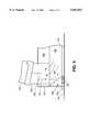
- FIG. 1is a side elevational view of a street sweeper having a high speed pick-up head in accordance with the present invention
- a high speed pick-up head constructed in accordance with the present inventionis generally designated by reference numeral 100.
- the pick-up head 100is specifically adapted to be mounted to an industrial street sweeper 10 in close proximity to a roadway surface 20 such as a street, a parking lot, an airport runway, or the like.
- the high speed pick-up head 100 of the present inventionis generally box-like or rectangular in configuration, with an associated width 102 and length 104.
- the width 102is generally parallel to the axles 34 of the sweeper 10 and extends in a generally transverse direction 24 with respect to the direction of travel 22.
- the length 104in contrast, is generally perpendicular to the axles 34 of the sweeper 10 and extends in a generally parallel direction with respect to the direction of travel 22.
- the width 102 of the pick-up head 100defines a path of debris removal along the surface 20 to be cleaned when the sweeper 10 moves along the direction of travel 22.
- a front edge wall 131extends downwardly from the front of the second panel 122 of the top cover portion 120
- a rear edge wall 132extends downwardly from the rear of the first panel 121 of the top cover portion 120
- opposed first and second side walls 133 and 134extend downwardly from the sides of the top cover portion 120 and interconnect the front and rear edge walls 131 and 132 to form the generally rectangular frame 110.
- the air pressure and air suction chambers 150 and 160are separated within the housing 110 by a cross-member 140 which extends downwardly between the two panels 121 and 122 of the top cover portion 120.
- a bottom panel 124extends substantially between the rear edge wall 132 and the cross-member 140 to provide the air pressure chamber 150 with a closed bottom portion or surface.
- the air suction chamber 160in contrast, has an open bottom portion which provides access to debris on the roadway surface 20.
- the inlet 152 of the pressure chamber 150is connected to the hopper 50 via a pressure tube 154, and the outlet 162 of the suction chamber 160 is connected to the hopper 50 via a suction tube 164.
- the open bottom portion 126 of the suction chamber 160is closed by the roadway surface 20. In this way, a substantially enclosed loop is formed between the pressure chamber 150, the nozzle 170, the bounded suction chamber 160, the outlet 162 of the suction chamber 160, the suction tube 164, the collection hopper 50, the pressure tube 154, and the inlet 152 of the pressure chamber 150.
- skid plate members 190are attached to the first and second side walls 133 and 134 of the housing 110, as shown in FIG. 1. Since the skid plate members 190 rub against the roadway surface 20, they are preferably formed of a high-strength material such as steel and include a carbide insert which reduces wear and spark formation.
- a debris separation system 60is disposed within the collection hopper 50 for removing relatively light debris 26 from the recirculating air flow pattern, as shown, for example, in FIG. 6.
- relatively heavy debris 28which is carried into the hopper 50 by the recirculating air flow pattern but falls to the bottom portion 54 of the hopper 50 due to the influence of gravity
- relatively light debris 26must be extracted or removed from the recirculating air flow pattern in some way. Indeed, if relatively light debris 26 is not removed from the recirculating air flow pattern, it may continuously cycle through the hopper 50, the pressure tube 154, the pick-up head 100, and the suction tube 164, respectively.
Landscapes
- Engineering & Computer Science (AREA)
- Architecture (AREA)
- Civil Engineering (AREA)
- Structural Engineering (AREA)
- Cleaning In General (AREA)
Abstract
Description
Claims (30)
Priority Applications (1)
| Application Number | Priority Date | Filing Date | Title |
|---|---|---|---|
| US08/805,076US5852847A (en) | 1997-02-21 | 1997-02-21 | High-speed pick-up head for a street sweeper |
Applications Claiming Priority (1)
| Application Number | Priority Date | Filing Date | Title |
|---|---|---|---|
| US08/805,076US5852847A (en) | 1997-02-21 | 1997-02-21 | High-speed pick-up head for a street sweeper |
Publications (1)
| Publication Number | Publication Date |
|---|---|
| US5852847Atrue US5852847A (en) | 1998-12-29 |
Family
ID=25190620
Family Applications (1)
| Application Number | Title | Priority Date | Filing Date |
|---|---|---|---|
| US08/805,076Expired - LifetimeUS5852847A (en) | 1997-02-21 | 1997-02-21 | High-speed pick-up head for a street sweeper |
Country Status (1)
| Country | Link |
|---|---|
| US (1) | US5852847A (en) |
Cited By (22)
| Publication number | Priority date | Publication date | Assignee | Title |
|---|---|---|---|---|
| EP1024229A1 (en)* | 1999-01-27 | 2000-08-02 | Schmidt Holding GmbH | Clearing vehicle |
| WO2002028257A1 (en)* | 2000-09-29 | 2002-04-11 | Oreck Holdings, Llc | Contoured intake ducts and fan housing assemblies for floor care machines |
| US20040045117A1 (en)* | 2002-09-06 | 2004-03-11 | Alowonle Musibau O. | Power management system for street sweeper |
| US6735814B2 (en) | 2000-10-05 | 2004-05-18 | Mister Services, Inc. | Apparatus for cleaning hard-to-reach areas |
| US6742219B2 (en) | 2001-10-29 | 2004-06-01 | Tennant Company | Air sweeping apparatus |
| US20050217064A1 (en)* | 2004-04-06 | 2005-10-06 | Anthony Libhart | Road/pavement cleaning machine having air-blast functionality |
| US20060053583A1 (en)* | 2004-09-16 | 2006-03-16 | Elgin Sweeper Co. | Street sweeper with litter hose |
| US20080083084A1 (en)* | 2006-10-06 | 2008-04-10 | Mark Schwarze | Modular hood for mechanized sweeper |
| US20080134457A1 (en)* | 2005-02-18 | 2008-06-12 | Irobot Corporation | Autonomous surface cleaning robot for dry cleaning |
| WO2009039624A3 (en)* | 2007-09-26 | 2009-05-22 | Roger Vanderlinden | Pick-up head having a re-circulating air system for a mobile sweeping vehicle |
| US20100011523A1 (en)* | 2008-07-15 | 2010-01-21 | Federal Signal Corporation | Side broom having memory recall and method for performing the same |
| CN102767150A (en)* | 2012-07-31 | 2012-11-07 | 中联重科股份有限公司 | Cleaning suction nozzle and cleaning vehicle |
| WO2012171098A1 (en)* | 2011-06-13 | 2012-12-20 | Roger Vanderlinden | Pick-up head system |
| US8360827B1 (en)* | 2010-03-09 | 2013-01-29 | Coughtry Richard J | Road marking removal system and method |
| US9282867B2 (en) | 2012-12-28 | 2016-03-15 | Irobot Corporation | Autonomous coverage robot |
| CN105568913A (en)* | 2014-11-07 | 2016-05-11 | 长沙中联重科环卫机械有限公司 | Cleaning suction nozzle and cleaning vehicle |
| US9483055B2 (en) | 2012-12-28 | 2016-11-01 | Irobot Corporation | Autonomous coverage robot |
| US9605395B1 (en)* | 2016-02-26 | 2017-03-28 | Richard Alston Hewitt | Street sweeper |
| US9725859B1 (en)* | 2016-02-22 | 2017-08-08 | Armando Hernandez | Pick-up head for street sweeping and cleaning vehicles |
| US9970167B1 (en)* | 2015-12-16 | 2018-05-15 | Newgen Sweepers, Inc. | Sweeper and frame for UTV |
| CN110714429A (en)* | 2018-07-12 | 2020-01-21 | 郑州宇通重工有限公司 | Suction nozzle device and cleaning vehicle using the same |
| IT201800010045A1 (en)* | 2018-11-05 | 2020-05-05 | Sam Progetti Srl | METHOD AND DEVICE FOR REMOVING DIRT FROM A SURFACE AND OPERATING MACHINE INCLUDING THIS DEVICE |
Citations (39)
| Publication number | Priority date | Publication date | Assignee | Title |
|---|---|---|---|---|
| US3512206A (en)* | 1966-08-30 | 1970-05-19 | Bernard W Young | Air flow surface cleaning apparatus |
| US3545181A (en)* | 1968-05-07 | 1970-12-08 | Bernard W Young | Air cleaning apparatus |
| US3755851A (en)* | 1971-10-28 | 1973-09-04 | Central Texas Iron Works Inc | Gas cleaning apparatus |
| GB1353376A (en)* | 1971-07-08 | 1974-05-15 | Johnston Bros Shropshire Ltd | Tool for removing obstructions from stone-crushing apparatus |
| US3886623A (en)* | 1972-07-14 | 1975-06-03 | Elgin Sweeper Co | Vacuum type sweeper |
| GB1460276A (en)* | 1973-02-27 | 1976-12-31 | Johnston Bros | Cleaning apparatus |
| US4109341A (en)* | 1976-02-05 | 1978-08-29 | Fmc Corporation | Unidirectional flow pickup hood for street sweepers |
| US4160302A (en)* | 1976-11-18 | 1979-07-10 | Johnston Brothers (Engineering) Limited | Refuse collecting vehicles |
| US4171551A (en)* | 1978-09-08 | 1979-10-23 | Elgin Sweeper Company | Spring suspended street sweeper having rear axle spring lockout |
| US4204849A (en)* | 1978-08-30 | 1980-05-27 | Donaldson Company, Inc. | Discharge valve assembly for multiple-stage dust collector |
| US4236871A (en)* | 1978-01-03 | 1980-12-02 | Johnston Brothers (Engineering) Limited | Centrifugal fan impellers with blades secured between plates |
| GB1588348A (en)* | 1978-05-09 | 1981-04-23 | Johnston Bros Eng Ltd | Apparatus for rotating vehicle bodies or other hollow bodies |
| US4347018A (en)* | 1979-08-09 | 1982-08-31 | Johnston Construction Limited | Lining or relining of tunnels |
| US4359801A (en)* | 1981-05-04 | 1982-11-23 | Tate Jimmy W | Pick-up head for surface cleaning apparatus |
| GB2128680A (en)* | 1982-10-08 | 1984-05-02 | Johnston Brothers | Hydraulic cylinder and piston |
| US4466156A (en)* | 1983-01-19 | 1984-08-21 | Tennant Company | Air velocity control mechanism for selective debris pickup |
| DE3316952A1 (en)* | 1983-05-09 | 1984-11-15 | Kuka Umwelttechnik GmbH, 8900 Augsburg | Method and device for cleaning road surfaces according to the circulating-air principle |
| GB2164378A (en)* | 1984-09-14 | 1986-03-19 | Johnston Eng Ltd | Suction nozzles for suction refuse collection vehicles |
| US4660248A (en)* | 1984-09-12 | 1987-04-28 | Tymco, Inc. | Pickup truck mounted sweeper |
| US4691402A (en)* | 1986-03-25 | 1987-09-08 | Veselka Kenneth R | Adjustable single lock gutter broom mechanism |
| US4773117A (en)* | 1987-03-04 | 1988-09-27 | Saito Motors Co., Ltd. | Rotary window cleaner |
| US4773121A (en)* | 1987-02-27 | 1988-09-27 | Tymco, Inc. | High speed pick-up head |
| GB2202884A (en)* | 1987-04-03 | 1988-10-05 | Johnston Eng Ltd | Road sweeping vehicle |
| US4779303A (en)* | 1986-02-20 | 1988-10-25 | Johnston Engineering Limited | Road sweeping vehicles |
| US4807327A (en)* | 1988-03-24 | 1989-02-28 | Elgin Sweeper Company | Dirt deflector for cleaning heads |
| US4885817A (en)* | 1986-09-09 | 1989-12-12 | Howa Machinery, Ltd. | Air-dust separation system for a pneumatic road-cleaning vehicle |
| US4903368A (en)* | 1988-06-16 | 1990-02-27 | Johnston Engineering Limited | Road sweeping vehicles |
| US4951347A (en)* | 1989-10-26 | 1990-08-28 | Elgin Sweeper Co. | Brush-type cleaning system |
| US5044887A (en)* | 1988-12-06 | 1991-09-03 | Johnston Engineering Limited | Blower fan impellers |
| US5056615A (en)* | 1989-07-12 | 1991-10-15 | Johnston Engineering Limited | Vehicle control system |
| US5072485A (en)* | 1988-04-29 | 1991-12-17 | Tymco, Inc. | Surface sweeping machine with over-the-cab hopper dumping |
| US5113548A (en)* | 1988-04-29 | 1992-05-19 | Tymco, Inc. | Surface sweeping machine with over-the-cab hopper dumping |
| EP0509353A1 (en)* | 1991-04-13 | 1992-10-21 | KROLL FAHRZEUGBAU GmbH | Method and container for transporting formless refuse for the purpose of its elimination |
| US5173989A (en)* | 1988-04-29 | 1992-12-29 | Tymco, Inc. | Surface sweeping machine with over-the-cab hopper dumping |
| DE4140926A1 (en)* | 1991-12-09 | 1993-06-17 | Kroll Fahrzeugbau Umwelt | Road sweeping machine with movable suction device - has carrier frame for suction mouth piece supported from vehicle chassis via guide rods providing wide pivot angle |
| DE4143123A1 (en)* | 1991-12-23 | 1993-07-01 | Kroll Fahrzeugbau Umwelt | Street brushing and cleaning machine - has rotary brush with extractor mouthpiece suspended from vehicle chassis by link rods and pneumatic or hydraulic rams. |
| GB2270334A (en)* | 1992-09-04 | 1994-03-09 | Kroll Fahrzeugbau Umwelt | Pneumatic refuse collection and filter apparatus for a roadsweeper |
| US5560065A (en)* | 1991-07-03 | 1996-10-01 | Tymco, Inc. | Broom assisted pick-up head |
| EP0803840A1 (en)* | 1996-04-25 | 1997-10-29 | Hewlett-Packard Company | Versatile scaling of drawings |
- 1997
- 1997-02-21USUS08/805,076patent/US5852847A/ennot_activeExpired - Lifetime
Patent Citations (41)
| Publication number | Priority date | Publication date | Assignee | Title |
|---|---|---|---|---|
| US3512206A (en)* | 1966-08-30 | 1970-05-19 | Bernard W Young | Air flow surface cleaning apparatus |
| US3545181A (en)* | 1968-05-07 | 1970-12-08 | Bernard W Young | Air cleaning apparatus |
| GB1353376A (en)* | 1971-07-08 | 1974-05-15 | Johnston Bros Shropshire Ltd | Tool for removing obstructions from stone-crushing apparatus |
| US3755851A (en)* | 1971-10-28 | 1973-09-04 | Central Texas Iron Works Inc | Gas cleaning apparatus |
| US3886623A (en)* | 1972-07-14 | 1975-06-03 | Elgin Sweeper Co | Vacuum type sweeper |
| GB1460276A (en)* | 1973-02-27 | 1976-12-31 | Johnston Bros | Cleaning apparatus |
| US4109341A (en)* | 1976-02-05 | 1978-08-29 | Fmc Corporation | Unidirectional flow pickup hood for street sweepers |
| US4160302A (en)* | 1976-11-18 | 1979-07-10 | Johnston Brothers (Engineering) Limited | Refuse collecting vehicles |
| US4236871A (en)* | 1978-01-03 | 1980-12-02 | Johnston Brothers (Engineering) Limited | Centrifugal fan impellers with blades secured between plates |
| GB1588348A (en)* | 1978-05-09 | 1981-04-23 | Johnston Bros Eng Ltd | Apparatus for rotating vehicle bodies or other hollow bodies |
| US4204849A (en)* | 1978-08-30 | 1980-05-27 | Donaldson Company, Inc. | Discharge valve assembly for multiple-stage dust collector |
| US4171551A (en)* | 1978-09-08 | 1979-10-23 | Elgin Sweeper Company | Spring suspended street sweeper having rear axle spring lockout |
| US4347018A (en)* | 1979-08-09 | 1982-08-31 | Johnston Construction Limited | Lining or relining of tunnels |
| US4359801A (en)* | 1981-05-04 | 1982-11-23 | Tate Jimmy W | Pick-up head for surface cleaning apparatus |
| GB2128680A (en)* | 1982-10-08 | 1984-05-02 | Johnston Brothers | Hydraulic cylinder and piston |
| US4466156A (en)* | 1983-01-19 | 1984-08-21 | Tennant Company | Air velocity control mechanism for selective debris pickup |
| DE3316952A1 (en)* | 1983-05-09 | 1984-11-15 | Kuka Umwelttechnik GmbH, 8900 Augsburg | Method and device for cleaning road surfaces according to the circulating-air principle |
| US4660248A (en)* | 1984-09-12 | 1987-04-28 | Tymco, Inc. | Pickup truck mounted sweeper |
| GB2164378A (en)* | 1984-09-14 | 1986-03-19 | Johnston Eng Ltd | Suction nozzles for suction refuse collection vehicles |
| US4779303A (en)* | 1986-02-20 | 1988-10-25 | Johnston Engineering Limited | Road sweeping vehicles |
| US4691402A (en)* | 1986-03-25 | 1987-09-08 | Veselka Kenneth R | Adjustable single lock gutter broom mechanism |
| US4885817A (en)* | 1986-09-09 | 1989-12-12 | Howa Machinery, Ltd. | Air-dust separation system for a pneumatic road-cleaning vehicle |
| US4773121A (en)* | 1987-02-27 | 1988-09-27 | Tymco, Inc. | High speed pick-up head |
| US4773117A (en)* | 1987-03-04 | 1988-09-27 | Saito Motors Co., Ltd. | Rotary window cleaner |
| GB2202884A (en)* | 1987-04-03 | 1988-10-05 | Johnston Eng Ltd | Road sweeping vehicle |
| US4807327A (en)* | 1988-03-24 | 1989-02-28 | Elgin Sweeper Company | Dirt deflector for cleaning heads |
| US5337444A (en)* | 1988-04-29 | 1994-08-16 | Tymco, Inc. | Surface sweeping machine with over-the-cab hopper dumping |
| US5072485A (en)* | 1988-04-29 | 1991-12-17 | Tymco, Inc. | Surface sweeping machine with over-the-cab hopper dumping |
| US5113548A (en)* | 1988-04-29 | 1992-05-19 | Tymco, Inc. | Surface sweeping machine with over-the-cab hopper dumping |
| US5173989A (en)* | 1988-04-29 | 1992-12-29 | Tymco, Inc. | Surface sweeping machine with over-the-cab hopper dumping |
| US5363533A (en)* | 1988-04-29 | 1994-11-15 | Tymco, Inc. | Surface sweeping machine with over-the-cab hopper dumping |
| US4903368A (en)* | 1988-06-16 | 1990-02-27 | Johnston Engineering Limited | Road sweeping vehicles |
| US5044887A (en)* | 1988-12-06 | 1991-09-03 | Johnston Engineering Limited | Blower fan impellers |
| US5056615A (en)* | 1989-07-12 | 1991-10-15 | Johnston Engineering Limited | Vehicle control system |
| US4951347A (en)* | 1989-10-26 | 1990-08-28 | Elgin Sweeper Co. | Brush-type cleaning system |
| EP0509353A1 (en)* | 1991-04-13 | 1992-10-21 | KROLL FAHRZEUGBAU GmbH | Method and container for transporting formless refuse for the purpose of its elimination |
| US5560065A (en)* | 1991-07-03 | 1996-10-01 | Tymco, Inc. | Broom assisted pick-up head |
| DE4140926A1 (en)* | 1991-12-09 | 1993-06-17 | Kroll Fahrzeugbau Umwelt | Road sweeping machine with movable suction device - has carrier frame for suction mouth piece supported from vehicle chassis via guide rods providing wide pivot angle |
| DE4143123A1 (en)* | 1991-12-23 | 1993-07-01 | Kroll Fahrzeugbau Umwelt | Street brushing and cleaning machine - has rotary brush with extractor mouthpiece suspended from vehicle chassis by link rods and pneumatic or hydraulic rams. |
| GB2270334A (en)* | 1992-09-04 | 1994-03-09 | Kroll Fahrzeugbau Umwelt | Pneumatic refuse collection and filter apparatus for a roadsweeper |
| EP0803840A1 (en)* | 1996-04-25 | 1997-10-29 | Hewlett-Packard Company | Versatile scaling of drawings |
Non-Patent Citations (2)
| Title |
|---|
| Sep. 1988 Brochure of Elgin Sweeper Company Elgin Eagle A new era in four wheel mechanical street sweeping begins.* |
| Sep. 1988 Brochure of Elgin Sweeper Company--Elgin Eagle--A new era in four-wheel mechanical street sweeping begins. |
Cited By (31)
| Publication number | Priority date | Publication date | Assignee | Title |
|---|---|---|---|---|
| EP1024229A1 (en)* | 1999-01-27 | 2000-08-02 | Schmidt Holding GmbH | Clearing vehicle |
| WO2002028257A1 (en)* | 2000-09-29 | 2002-04-11 | Oreck Holdings, Llc | Contoured intake ducts and fan housing assemblies for floor care machines |
| US6792649B2 (en) | 2000-09-29 | 2004-09-21 | Oreck Holdings, Llc | Contoured intake ducts and fan housing assemblies for floor care machines |
| US6735814B2 (en) | 2000-10-05 | 2004-05-18 | Mister Services, Inc. | Apparatus for cleaning hard-to-reach areas |
| US6742219B2 (en) | 2001-10-29 | 2004-06-01 | Tennant Company | Air sweeping apparatus |
| US20040045117A1 (en)* | 2002-09-06 | 2004-03-11 | Alowonle Musibau O. | Power management system for street sweeper |
| US6959466B2 (en) | 2002-09-06 | 2005-11-01 | Tennant Company | Power management system for street sweeper |
| US7621018B2 (en)* | 2004-04-06 | 2009-11-24 | Schwarze Industries, Inc. | Road/pavement cleaning machine having air-blast functionality |
| US20050217064A1 (en)* | 2004-04-06 | 2005-10-06 | Anthony Libhart | Road/pavement cleaning machine having air-blast functionality |
| US20060053583A1 (en)* | 2004-09-16 | 2006-03-16 | Elgin Sweeper Co. | Street sweeper with litter hose |
| US7424767B2 (en) | 2004-09-16 | 2008-09-16 | Elgin Sweeper Co. | Street sweeper with litter hose |
| US20080134457A1 (en)* | 2005-02-18 | 2008-06-12 | Irobot Corporation | Autonomous surface cleaning robot for dry cleaning |
| US8739355B2 (en)* | 2005-02-18 | 2014-06-03 | Irobot Corporation | Autonomous surface cleaning robot for dry cleaning |
| US8782848B2 (en) | 2005-02-18 | 2014-07-22 | Irobot Corporation | Autonomous surface cleaning robot for dry cleaning |
| US20080083084A1 (en)* | 2006-10-06 | 2008-04-10 | Mark Schwarze | Modular hood for mechanized sweeper |
| WO2009039624A3 (en)* | 2007-09-26 | 2009-05-22 | Roger Vanderlinden | Pick-up head having a re-circulating air system for a mobile sweeping vehicle |
| US20100011523A1 (en)* | 2008-07-15 | 2010-01-21 | Federal Signal Corporation | Side broom having memory recall and method for performing the same |
| US8136193B2 (en) | 2008-07-15 | 2012-03-20 | Federal Signal Corporation | Side broom having memory recall and method for performing the same |
| US8360827B1 (en)* | 2010-03-09 | 2013-01-29 | Coughtry Richard J | Road marking removal system and method |
| WO2012171098A1 (en)* | 2011-06-13 | 2012-12-20 | Roger Vanderlinden | Pick-up head system |
| CN102767150A (en)* | 2012-07-31 | 2012-11-07 | 中联重科股份有限公司 | Cleaning suction nozzle and cleaning vehicle |
| US9483055B2 (en) | 2012-12-28 | 2016-11-01 | Irobot Corporation | Autonomous coverage robot |
| US9282867B2 (en) | 2012-12-28 | 2016-03-15 | Irobot Corporation | Autonomous coverage robot |
| US10162359B2 (en) | 2012-12-28 | 2018-12-25 | Irobot Corporation | Autonomous coverage robot |
| CN105568913A (en)* | 2014-11-07 | 2016-05-11 | 长沙中联重科环卫机械有限公司 | Cleaning suction nozzle and cleaning vehicle |
| CN105568913B (en)* | 2014-11-07 | 2017-08-08 | 长沙中联重科环境产业有限公司 | Clean- suction nozzle and cleaning car |
| US9970167B1 (en)* | 2015-12-16 | 2018-05-15 | Newgen Sweepers, Inc. | Sweeper and frame for UTV |
| US9725859B1 (en)* | 2016-02-22 | 2017-08-08 | Armando Hernandez | Pick-up head for street sweeping and cleaning vehicles |
| US9605395B1 (en)* | 2016-02-26 | 2017-03-28 | Richard Alston Hewitt | Street sweeper |
| CN110714429A (en)* | 2018-07-12 | 2020-01-21 | 郑州宇通重工有限公司 | Suction nozzle device and cleaning vehicle using the same |
| IT201800010045A1 (en)* | 2018-11-05 | 2020-05-05 | Sam Progetti Srl | METHOD AND DEVICE FOR REMOVING DIRT FROM A SURFACE AND OPERATING MACHINE INCLUDING THIS DEVICE |
Similar Documents
| Publication | Publication Date | Title |
|---|---|---|
| US5852847A (en) | High-speed pick-up head for a street sweeper | |
| CA1092758A (en) | Sweeper hood with transverse air duct and broom compartments | |
| US4310944A (en) | Surface maintenance machine having air recirculation | |
| US4006511A (en) | Sweeper with recirculation hood and independent filter system | |
| US4570287A (en) | Method of and apparatus for picking up refuse from a surface, such as a track bed | |
| US6742219B2 (en) | Air sweeping apparatus | |
| US4206530A (en) | Surface maintenance machine having air recirculation | |
| US6195836B1 (en) | Mechanical surface cleaning vehicle for fine particulate removal | |
| US5839157A (en) | Street sweeper pick-up head | |
| US8117711B2 (en) | High efficiency intake hood system for mobile sweeper vehicles | |
| US5659921A (en) | Sweeper with double side skirts for dust control | |
| US3221358A (en) | High-speed roadway vacuum cleaner | |
| US4359801A (en) | Pick-up head for surface cleaning apparatus | |
| KR101898100B1 (en) | a road sweeping vehicle by air dry | |
| US4109341A (en) | Unidirectional flow pickup hood for street sweepers | |
| CN106087832B (en) | Air stream drives for road sweeper pick up dirt device and road sweeper | |
| CN109083070B (en) | Brushless disc high-pressure gas sweeper | |
| US6154922A (en) | Self-propelled factory floor cleaning vehicle | |
| US20090089964A1 (en) | Pick-up head having a re-circulating air system for a mobile sweeping vehicle | |
| US4807327A (en) | Dirt deflector for cleaning heads | |
| US4466156A (en) | Air velocity control mechanism for selective debris pickup | |
| US3862469A (en) | Vacuum cleaner | |
| US3004279A (en) | Mobile vacuum cleaning machine for streets, airport runways and the like | |
| US3605170A (en) | Mobile suction cleaning device | |
| US7191485B1 (en) | Lawn waste sweeper with recirculating airstream |
Legal Events
| Date | Code | Title | Description |
|---|---|---|---|
| AS | Assignment | Owner name:ELGIN SWEEPER COMPANY, ILLINOIS Free format text:ASSIGNMENT OF ASSIGNORS INTEREST;ASSIGNORS:WEISS, CHRISTOPHER R.;JAJKO, ROBERT A.;GRANDERSON, LARRY D. SR.;AND OTHERS;REEL/FRAME:009491/0058;SIGNING DATES FROM 19980917 TO 19980922 | |
| STCF | Information on status: patent grant | Free format text:PATENTED CASE | |
| FPAY | Fee payment | Year of fee payment:4 | |
| FPAY | Fee payment | Year of fee payment:8 | |
| FPAY | Fee payment | Year of fee payment:12 | |
| AS | Assignment | Owner name:BANK OF MONTREAL, AS COLLATERAL AGENT, ILLINOIS Free format text:SECURITY AGREEMENT;ASSIGNOR:ELGIN SWEEPER COMPANY;REEL/FRAME:026254/0141 Effective date:20110414 | |
| AS | Assignment | Owner name:TPG SPECIALTY LENDING, INC., AS COLLATERAL AGENT, Free format text:GRANT OF A SECURITY INTEREST - PATENTS;ASSIGNORS:FEDERAL SIGNAL CORPORATION;ELGIN SWEEPER COMPANY;FEDERAL APD INCORPORATED;AND OTHERS;REEL/FRAME:027745/0171 Effective date:20120222 Owner name:WELLS FARGO CAPITAL FINANCE, LLC, AS AGENT, ILLINO Free format text:SECURITY AGREEMENT;ASSIGNORS:FEDERAL SIGNAL CORPORATION;JETSTREAM OF HOUSTON, INC.;PIPS TECHNOLOGY INC.;AND OTHERS;REEL/FRAME:027743/0051 Effective date:20120222 | |
| AS | Assignment | Owner name:ELGIN SWEEPER COMPANY, ILLINOIS Free format text:RELEASE AND REASSIGNMENT OF PATENTS;ASSIGNOR:BANK OF MONTEAL;REEL/FRAME:027756/0262 Effective date:20120222 | |
| AS | Assignment | Owner name:WELLS FARGO BANK, NATIONAL ASSOCIATION (AS ADMINIS Free format text:SECURITY AGREEMENT;ASSIGNOR:ELGIN SWEEPER COMPANY;REEL/FRAME:029996/0737 Effective date:20130313 | |
| AS | Assignment | Owner name:ELGIN SWEEPER COMPANY, ILLINOIS Free format text:RELEASE BY SECURED PARTY;ASSIGNOR:WELLS FARGO CAPITAL FINANCE, LLC;REEL/FRAME:030290/0956 Effective date:20130313 Owner name:FST OF CALIFORNIA LLC, ILLINOIS Free format text:RELEASE BY SECURED PARTY;ASSIGNOR:WELLS FARGO CAPITAL FINANCE, LLC;REEL/FRAME:030290/0956 Effective date:20130313 Owner name:JETSTREAM OF HOUSTON, LLP, ILLINOIS Free format text:RELEASE BY SECURED PARTY;ASSIGNOR:WELLS FARGO CAPITAL FINANCE, LLC;REEL/FRAME:030290/0956 Effective date:20130313 Owner name:FEDERAL SIGNAL CORPORATION, ILLINOIS Free format text:RELEASE BY SECURED PARTY;ASSIGNOR:WELLS FARGO CAPITAL FINANCE, LLC;REEL/FRAME:030290/0956 Effective date:20130313 Owner name:FST OF TENNESSEE, INC., ILLINOIS Free format text:RELEASE BY SECURED PARTY;ASSIGNOR:WELLS FARGO CAPITAL FINANCE, LLC;REEL/FRAME:030290/0956 Effective date:20130313 Owner name:GUZZLER MANUFACTURING, INC., ILLINOIS Free format text:RELEASE BY SECURED PARTY;ASSIGNOR:WELLS FARGO CAPITAL FINANCE, LLC;REEL/FRAME:030290/0956 Effective date:20130313 Owner name:FST OF MICHIGAN, ILLINOIS Free format text:RELEASE BY SECURED PARTY;ASSIGNOR:WELLS FARGO CAPITAL FINANCE, LLC;REEL/FRAME:030290/0956 Effective date:20130313 Owner name:VACTOR MANUFACTURING, INC., ILLINOIS Free format text:RELEASE BY SECURED PARTY;ASSIGNOR:WELLS FARGO CAPITAL FINANCE, LLC;REEL/FRAME:030290/0956 Effective date:20130313 | |
| AS | Assignment | Owner name:VACTOR MANUFACTURING INC., ILLINOIS Free format text:RELEASE BY SECURED PARTY;ASSIGNOR:TPG SPECIALTY LENDING, INC.;REEL/FRAME:030540/0788 Effective date:20130313 Owner name:JETSTREAM OF HOUSTON, LLP, ILLINOIS Free format text:RELEASE BY SECURED PARTY;ASSIGNOR:TPG SPECIALTY LENDING, INC.;REEL/FRAME:030540/0788 Effective date:20130313 Owner name:ELGIN SWEEPER COMPANY, ILLINOIS Free format text:RELEASE BY SECURED PARTY;ASSIGNOR:TPG SPECIALTY LENDING, INC.;REEL/FRAME:030540/0788 Effective date:20130313 Owner name:FEDERAL SIGNAL CREDIT CORPORATION, ILLINOIS Free format text:RELEASE BY SECURED PARTY;ASSIGNOR:TPG SPECIALTY LENDING, INC.;REEL/FRAME:030540/0788 Effective date:20130313 Owner name:FST OF MICHIGAN, ILLINOIS Free format text:RELEASE BY SECURED PARTY;ASSIGNOR:TPG SPECIALTY LENDING, INC.;REEL/FRAME:030540/0788 Effective date:20130313 Owner name:FEDERAL SIGNAL OF TEXAS CORP., ILLINOIS Free format text:RELEASE BY SECURED PARTY;ASSIGNOR:TPG SPECIALTY LENDING, INC.;REEL/FRAME:030540/0788 Effective date:20130313 Owner name:FS DEPOT, INC., ILLINOIS Free format text:RELEASE BY SECURED PARTY;ASSIGNOR:TPG SPECIALTY LENDING, INC.;REEL/FRAME:030540/0788 Effective date:20130313 Owner name:FS SUB, LLC, ILLINOIS Free format text:RELEASE BY SECURED PARTY;ASSIGNOR:TPG SPECIALTY LENDING, INC.;REEL/FRAME:030540/0788 Effective date:20130313 Owner name:GUZZLER MANUFACTURING, INC., ILLINOIS Free format text:RELEASE BY SECURED PARTY;ASSIGNOR:TPG SPECIALTY LENDING, INC.;REEL/FRAME:030540/0788 Effective date:20130313 Owner name:FST OF TENNESSEE, INC., ILLINOIS Free format text:RELEASE BY SECURED PARTY;ASSIGNOR:TPG SPECIALTY LENDING, INC.;REEL/FRAME:030540/0788 Effective date:20130313 Owner name:FEDERAL MERGER CORPORATION, ILLINOIS Free format text:RELEASE BY SECURED PARTY;ASSIGNOR:TPG SPECIALTY LENDING, INC.;REEL/FRAME:030540/0788 Effective date:20130313 Owner name:FEDERAL SIGNAL CORPORATION, ILLINOIS Free format text:RELEASE BY SECURED PARTY;ASSIGNOR:TPG SPECIALTY LENDING, INC.;REEL/FRAME:030540/0788 Effective date:20130313 Owner name:JETSTREAM OF HOUSTON, INC., ILLINOIS Free format text:RELEASE BY SECURED PARTY;ASSIGNOR:TPG SPECIALTY LENDING, INC.;REEL/FRAME:030540/0788 Effective date:20130313 Owner name:FST OF CALIFORNIA LLC, ILLINOIS Free format text:RELEASE BY SECURED PARTY;ASSIGNOR:TPG SPECIALTY LENDING, INC.;REEL/FRAME:030540/0788 Effective date:20130313 |