US5851207A - Freely separable surgical drill guide and plate - Google Patents
Freely separable surgical drill guide and plateDownload PDFInfo
- Publication number
- US5851207A US5851207AUS08/886,547US88654797AUS5851207AUS 5851207 AUS5851207 AUS 5851207AUS 88654797 AUS88654797 AUS 88654797AUS 5851207 AUS5851207 AUS 5851207A
- Authority
- US
- United States
- Prior art keywords
- rim
- collet
- diameter
- plate
- neck
- Prior art date
- Legal status (The legal status is an assumption and is not a legal conclusion. Google has not performed a legal analysis and makes no representation as to the accuracy of the status listed.)
- Ceased
Links
- 210000000988bone and boneAnatomy0.000claimsabstractdescription29
- 238000000605extractionMethods0.000claimsdescription6
- 238000010276constructionMethods0.000claimsdescription2
- 210000001519tissueAnatomy0.000description12
- 230000001012protectorEffects0.000description10
- 238000003780insertionMethods0.000description7
- 230000037431insertionEffects0.000description7
- 238000000034methodMethods0.000description7
- 238000002513implantationMethods0.000description6
- 238000005553drillingMethods0.000description4
- 230000006835compressionEffects0.000description3
- 238000007906compressionMethods0.000description3
- 238000003786synthesis reactionMethods0.000description3
- 239000012634fragmentSubstances0.000description2
- 238000009877renderingMethods0.000description2
- 238000009987spinningMethods0.000description2
- 230000009471actionEffects0.000description1
- 238000004873anchoringMethods0.000description1
- 230000009286beneficial effectEffects0.000description1
- 239000008280bloodSubstances0.000description1
- 210000004369bloodAnatomy0.000description1
- 230000008878couplingEffects0.000description1
- 238000010168coupling processMethods0.000description1
- 238000005859coupling reactionMethods0.000description1
- 230000006837decompressionEffects0.000description1
- 230000003247decreasing effectEffects0.000description1
- 230000000694effectsEffects0.000description1
- 210000003238esophagusAnatomy0.000description1
- 238000003384imaging methodMethods0.000description1
- 239000007943implantSubstances0.000description1
- 230000007774longtermEffects0.000description1
- 230000001045lordotic effectEffects0.000description1
- 239000000463materialSubstances0.000description1
- 230000007246mechanismEffects0.000description1
- 238000012986modificationMethods0.000description1
- 230000004048modificationEffects0.000description1
- 230000000149penetrating effectEffects0.000description1
- 230000008569processEffects0.000description1
- 239000007787solidSubstances0.000description1
- 210000000278spinal cordAnatomy0.000description1
- 238000001356surgical procedureMethods0.000description1
- 231100000732tissue residueToxicity0.000description1
- 210000000689upper legAnatomy0.000description1
- 230000003313weakening effectEffects0.000description1
Images


Classifications
- A—HUMAN NECESSITIES
- A61—MEDICAL OR VETERINARY SCIENCE; HYGIENE
- A61B—DIAGNOSIS; SURGERY; IDENTIFICATION
- A61B17/00—Surgical instruments, devices or methods
- A61B17/16—Instruments for performing osteoclasis; Drills or chisels for bones; Trepans
- A61B17/17—Guides or aligning means for drills, mills, pins or wires
- A61B17/1728—Guides or aligning means for drills, mills, pins or wires for holes for bone plates or plate screws
- A—HUMAN NECESSITIES
- A61—MEDICAL OR VETERINARY SCIENCE; HYGIENE
- A61B—DIAGNOSIS; SURGERY; IDENTIFICATION
- A61B17/00—Surgical instruments, devices or methods
- A61B17/16—Instruments for performing osteoclasis; Drills or chisels for bones; Trepans
- A61B17/17—Guides or aligning means for drills, mills, pins or wires
- A61B17/1739—Guides or aligning means for drills, mills, pins or wires specially adapted for particular parts of the body
- A61B17/1757—Guides or aligning means for drills, mills, pins or wires specially adapted for particular parts of the body for the spine
- Y—GENERAL TAGGING OF NEW TECHNOLOGICAL DEVELOPMENTS; GENERAL TAGGING OF CROSS-SECTIONAL TECHNOLOGIES SPANNING OVER SEVERAL SECTIONS OF THE IPC; TECHNICAL SUBJECTS COVERED BY FORMER USPC CROSS-REFERENCE ART COLLECTIONS [XRACs] AND DIGESTS
- Y10—TECHNICAL SUBJECTS COVERED BY FORMER USPC
- Y10S—TECHNICAL SUBJECTS COVERED BY FORMER USPC CROSS-REFERENCE ART COLLECTIONS [XRACs] AND DIGESTS
- Y10S606/00—Surgery
- Y10S606/902—Cortical plate specifically adapted for a particular bone
- Y10S606/906—Small bone plate
Definitions
- the present inventionrelates to a surgical drill guide and a surgical plate that are attachable to each other for retaining a precise alignment therebetween. More particularly, the invention relates to a bone plate with a fastener hole and surgical drill guide with an expandable collet having a rim that, when contracted, is smaller than the fastener hole.
- Surgical fixation platesare used in many procedures to mend, align, and alter compression of patients' bones. These plates are primarily secured to the patient's bones by a plurality of fasteners such as screws. Proper orientation and alignment of fasteners and secure surgical fixation of the plates is crucial to avoiding future complications after implantation. This is especially the case for cervical spine locking-plates, such as sold by SYNTHES Spine. These plates are used for long term, intravertebral fixation, bone-fragment fixation, and anterior decompression in the cervical region of the spine. Locking plates enable secure monocortical implantation, meaning that their screws need only penetrate the anterior bone cortex. In conventional plates, screws must pass through both the anterior and posterior bone cortices to attain sufficient support. In passing through both cortices, conventional plates risk penetrating the spinal chord.
- each plate holeshould coaxially align with its screw, i.e., each plate hole has an axis that must align with the screw axis. Otherwise, screws do not seat correctly with the plate. Thus, misalignments can potentially damage tissues, including the spinal cord, or lead to improperly secured plates.
- Cervical locking platesin particular demand precise fastener alignment. Cervical locking plates are generally about 2 mm thick. Some screw holes in these plates are inclined by 12° to the surface of the plate to permit optimal screw placement in the cervical region of the spine.
- Anchor screwssecure the locking plate to the vertebral body.
- Anchor screwshave hollow, longitudinally slotted expansive heads that must fit snugly within a plate's screw hole. These screws are externally threaded to secure to the vertebral bone and the plate. These screws are also threaded internally from their head through a shallow portion of their shaft. Once a surgeon implants an anchor screw, he or she screws a small locking screw into the head of the anchor screw. This locking screw expands the head of the anchor screw so that the head presses outwardly against the locking plate's hole for a compression fit. This compression fit locks the screw in place and creates a solid coupling between the plate and the screw, preventing motion between them and preventing the screw from backing out from the plate, which may damage the esophagus.
- Known drill guides for locking platesare generally a cylindrical tube shaped to receive and guide a drill bit. Most known guides also have a handle. A tip of the tube is shaped to slide into screw holes. A shoulder near the guide tip rests against a modest countersink in the screw hole to limit the guide's insertion into the hole. Constant axial pressure against the plate is required to maintain the guide in the hole, although it is sometimes beneficial to limit unnecessary pressure against the spine during drilling. Also, a clearance between the tip of the guide and the hole is provided to ease insertion into the hole. Due to this clearance, the diminutive thickness of the plate, and the small size of the countersink, an amount of angular play exists in this system. Other similar guides, though shown with femur fixation-plates, are disclosed in U.S. Pat. Nos. 2,494,229, and 5,417,367.
- a more accurate drill guideis sold by SYNTHES Spine and shown in its catalog dated 1995, in which angular play is reduced and which does not require a constant force against the plate.
- This drill guidehas an expanding collet formed with a plurality of fingers disposed coaxially about a drill guide sleeve.
- the sleeveis conical, and when it is slid forward, it spreads the collet fingers to lock them against the inside walls of a screw hole in a cervical spine locking plate.
- a scissoring handle linked to the collet and the sleevecontrols the relative forward and backward motion therebetween.
- the colletAt the forward tip of the drill guide, the collet has a neck, designed to press against the inside walls of the screw hole. Adjacent this neck is a radially extending rim, which, in a naturally assumed contracted position, has a diameter slightly larger than the screw hole, providing an interference fit.
- the greater diameter of the rimprovides a surgeon with a detectable snap and decreased resistance to insertion of the collet as the rim passes to the far side of the hole.
- the surgeonTo extract the collet from the screw hole, the surgeon must apply a slight force to pry the rim back through the smaller diameter walls of the hole, as these force the rim to contract to the smaller diameter.
- a drill guideis needed that can disengageably lock to a surgical plate fastener hole, but without catching as the drill guide is extracted therefrom.
- the inventionis directed to instrumentation for fixing bones or bone fragments to each other.
- the instrumentationincludes a bone plate for attaching to the bones, and a drill guide.
- the bone platehas at least one fastener hole through which fasteners, such as locking bone screws, fasten the plate to the bones.
- the holehas an inner wall with a predetermined hole diameter.
- the drill guidehas a guide member for guiding a drill bit.
- a hollow collet disposed coaxially with the guide memberhas as radially expandable forward end with a neck and outwardly projecting neck and an outwardly projecting rim forward of the neck.
- the neckis configured to press outwardly against an inner wall of the plate hole when collet is in the expanded position.
- the rimis freely extractable through the plate hole when the collet is in a contracted position. However, when the collet is in an expanded position, the rim does not fit through the plate hole.
- the rimdefines a contracted outer rim diameter smaller than the hole diameter when the rim is in a contracted position, rendering the rim freely extractable from the hole.
- the rimWhen the rim is in an expanded position, it defines an expanded outer rim diameter larger than the hole diameter, rendering the rim impassable through the plate hole.
- the contracted rim diameteris preferably between 0.1 mm and 0.3 mm smaller than the hole diameter, or about 95% of the hole diameter.
- the rimprotrudes radially from the neck by less than 0.1 mm. In one embodiment, the diameter of the rim is equal to that of the neck.
- the rimhas a rounded cross section in a plane extending through the axis of the neck and rim, preventing the rim from catching on the plate during its extraction therefrom. Also, a surface of the rim substantially adjacent the neck and configured at a first angle thereto of preferably less than about 55°, and more preferably of about 45°.
- the guide memberincludes a guide sleeve movably axially and telescopically received within the collet.
- the sleevedefines a guide bore through which it axially receive and guide a drill bit.
- the sleevebiases the collet towards the expanded position.
- the sleevehas a surface tapered inwardly at a second angle of between 3° and 5° to its axis to effect the expansion of the collet. More preferably this taper angle is about 4°.
- the inventionprovides a surgical drill guide and a bone plate that are securable to one another, but which do not catch on each other upon drill guide extraction.
- the guideis unfetteredly and freely removable from the plate.
- FIG. 1shows a side view of a surgical drill guide according to the invention
- FIG. 2is a cross-section, cutaway view of an expandable collet in a contracted position and a guide sleeve according to the invention
- FIG. 3is an enlarged cross-section of the collet being inserted into a locking plate
- FIG. 4is a further enlarged view of the front of the collet
- FIG. 5is a cross-section of a drill guide assembly of the invention locked coaxially to a screw hole and aligned at an angle to the surface of a locking plate;
- FIG. 5Ais an expanded cross-section of the forward portion of the drill guide assembly of FIG. 3;
- FIG. 6is a cross-section of a drill guide assembly according to the invention locked coaxially to a screw hole extending perpendicularly to the surface of the locking plate;
- FIG. 6Ais an expanded cross-section of the forward portion of the drill guide assembly of FIG. 4;
- FIG. 7is a flow chart of the method of implanting a cervical spine locking plate.
- FIG. 8is a flow chart of the method for using the drill guide assembly to drill an aligned hole.
- FIG. 1shows an embodiment of a surgical drill guide assembly 8 according to the invention, which is adapted for use with a cervical spine locking plate.
- a collet 10Telescopically and slideably engaged within collet 10 is a guide sleeve 12.
- a tissue protector 14extends rearwardly from the sleeve 12.
- the collet 10, sleeve 12, and tissue protector 14are adapted to axially receive a drill bit 16, and the guide sleeve 12 is sized to retain the spinning bit 16 in a precise coaxial alignment.
- the collet 10is fixed to a remote rear handle-member 18.
- the handle member 18is pivotably attached to a scissor grip 20 by a handle pin 22.
- handle member 18 and scissor grip 20form a drill guide assembly handle 23, which allows a user to maneuver and use the drill guide assembly.
- the scissor grip 20has an arm 24 that extends to the opposite side of the handle pin 22 from the grip 20 to pivotably attach to an actuation bar 26 at actuation pin 28.
- An end of the bar 26is pivotably attached with the sleeve 12 at sleeve pin 30.
- the entire drill guide assembly in this embodimentforms a four bar linkage.
- the arm 24forces the actuation bar 26 forward.
- This in turnforces the sleeve 12 to slide forward, deeper into collet 10.
- no part of the sleeve 12can slide further forward than the front of the collet 10.
- the scissor grip 20has a forward wall 32 and a rear wall 34 to help the surgeon manually force the sleeve 12 forward or backward by closing or opening the guide sleeve assembly with only one hand.
- leaf springs 36are fastened to the handle member 18 and the scissor grip 20 to further assist rearward motion of the sleeve 12 by biasing the handle 23 towards an open position.
- the collet 10has a forward end 40 that is radially expandable.
- the collethas a plurality of fingers 38 that can be spread apart to expand the forward end 40 of the collet 10.
- the collet 10coaxially receives the sleeve 12 about an axis 37. Also, a guide bore 39 extends along axis 37 for guiding a drill bit coaxially therein.
- the forward end 40 of collet 10is preferably comprised of longitudinally extending fingers 38.
- the fingers 38are divided by slots 42 extending longitudinally between adjacent fingers 38. These fingers 38 are resiliently biased inwardly and naturally assume an inward disposition when in a relaxed state and when the sleeve 12 is in the unlocked position, as shown in the figure. In the figure, a portion of the sleeve 12 has been cut away to better illustrate the slots 42.
- the fingers 38form a radially expandable circumferential neck 44.
- neck 44At the back end of and adjacent to neck 44 is a shoulder 46, and at the front end of and adjacent to neck 44 are protrusions that form a radially expandable rim 48.
- protrusionsthat form a radially expandable rim 48.
- FIG. 3shows the collet 10 being inserted into a screw hole 64 in a locking plate 56.
- the colletis in its natural, contracted position.
- the collet 10is resiliently biased towards this position, in which the neck 44 has a contracted diameter d1 and the rim has a contracted rim diameter d2.
- the screw hole 64has an inner wall with a hole diameter d3.
- the contracted rim diameter d2is smaller than the hole diameter d3 to permit free and unfettered extraction of the rim 48 from the hole 64.
- the contracted rim diametermeasures between 0.1 mm and 0.3 mm less than the hole diameter d3. More preferably, the rim diameter d2 is 0.2 mm smaller than the hole.
- the contracted rim diameter d2is preferably between 4.2 mm and 4.4 mm in a drill guide that functions with a hole diameter d3 of about 4.5 mm.
- the contracted rim diameteris approximately 95% the size of the hole diameter.
- the contracted rim diameter d2is preferably about between 1 mm and 2 mm larger than the contracted neck diameter d1.
- the rim 48protrudes from the neck 44 by a preferred 1 mm.
- the contracted neck diameter d1is preferably more than 95% as large as the contracted rim diameter d2.
- a rim 48provides the surgeon with a detectable feel for when the rim has completely passed the through the hole 64.
- the rim 48may be eliminated completely, for instance by reducing the contracted rim diameter d2 to an equal size as the contracted neck diameter d1. These embodiments, though, would lack the signal to the surgeon produced by full passage of the rim 48 through the hole 64.
- the rim 48is rounded in a cross-section taken parallel to axis 37.
- the cross sectionpreferably curves around a radius 49 of about 0.15 mm.
- a surface of the rim 48 disposed adjacent the neck 44is configured at an angle 51 of less than 55° to the neck 44, and most preferably at about 45° thereto. In some embodiments, this angled surface is preferably joined to the neck 44 via a narrow surface 47 of concave radius.
- shoulder 46has a diameter d4 that is greater than the contracted rim diameter d2.
- the shoulder 46has a diameter that is greater than the hole diameter d3 such that the shoulder 46 cannot be inserted therethrough.
- the neck 44is slightly longer than the thickness of the hole wall 65, such that the neck can abut the wall of the locking plate hole and the rim 48 can abut the inside surface of a locking plate 56. In this manner, the drill guide assembly can be secured to the locking plate 56, restricting relative movement.
- the inside of the expandable forward end 40 the collet 10preferably has a variable inner diameter.
- the fingers 38have a step 50 or a taper, resulting in a smaller inner collet 10 diameter forward of the step 50.
- the guide sleeve 12includes a forward portion 52 that cooperates with the fingers 38 to expand the fingers 38 when the guide sleeve 12 is moved into a locked position.
- the guide sleeve 12is tapered at taper angle 53 to the axis 37 to form a conical forward portion 52.
- the conical section 52 of guide sleeve 12pushes outwardly against the inner surface of the collet 10 as the guide sleeve 12 is moved forward to expand the forward end 40.
- the conical sectionmates with and pushes against the inner collet 10 surface forward of step 50 to push the fingers 38 radially outward.
- the conical section 52allows the fingers 38 to return to a relaxed, contracted position. This allows the collet 10 to be inserted and retracted from the plate hole.
- the taper angle 53is preferably between 3° and 5°, and more preferably about 4°.
- the inner surface of the collet 10 forward of the step 50is also preferably tapered at an angle 55 to axis 37 that is substantially equal to taper angle 53. This range of angles provides a desirable amount of movement of the sleeve 12 within the collet 10 to bias the collet 10 from a contracted position to an expanded position.
- the guide sleeve 12When the surgeon squeezes the handle 23, the guide sleeve 12 is moved forward and the conical section 52 cooperatively forces the inner surface of the collet 10 beyond step 50 and fingers 38 radially outward.
- the forward motion of the guide sleeve 12 towards a forward positionexpands the forward end 40 of the collet 10 to an expanded position.
- the neck 44can be expanded to abut the inner wall of the plate screw hole and the rim 48 is expanded to abut the inner surface of the locking plate.
- the expanded outer diameter d5 of the rim 48is greater than the plate hole diameter d3 so that the guide cannot be retracted from the plate hole, as shown in FIG. 6A.
- FIGS. 5-6Ashow the sleeve 12 in a locked, forward position, and the expandable end 40 in an expanded position and locked to different screw holes of the same predetermined diameter d3.
- screw hole 54 in locking plate 56is disposed at an angle of about 12° to the locking plate's 56 outside surface 58.
- the drill guide assemblyis configured so that when the collet 10 is expanded, as shown, the neck 44 presses outwardly against interior wall 60 of screw hole 54, positively gripping the wall 60.
- the rim 48preferably abuts the back surface of the plate 56 so that the neck positions the guide.
- the shoulder 46on the other hand, preferably does not abut the outside surface 58 of the plate 56.
- the axis of the drill guideis aligned with the axis of the plate screw hole 54.
- the axis of the hole drilled into the bonewill also be aligned with the axis of the plate screw hole 54.
- an anchoring screw inserted into the drilled holewill be centered and aligned with the plate screw hole 54, i.e., they too will be substantially co-axially aligned.
- rim 48aids in preventing the collet 10 from sliding backwards, out of the hole 54.
- the rim 48is adapted to rest against the far side of the plate 56, near the perimeter of the hole 54. Note that when the drill guide of this embodiment is locked to an angled hole 54, as shown, only a segment of rim 48 may actually contact the back of the plate 56. This small contact surface suffices to retain the collet 10 within the hole 54.
- a gap 62remains between the forwardly facing surface of shoulder 46 and the plate 56. This is because, in the preferred embodiment, the shoulder 46 is not necessary for achieving a proper drill alignment or a secure locking. Consequentially, a surgeon need not press the drill guide against the locking plate 56 to keep the guide properly seated within the hole 54.
- FIGS. 6 and 6Ashow the same embodiment of the invention locked to a screw hole 64 in a different part of locking plate 56.
- Hole 64is perpendicular to the locking plate's 56 surface 66.
- most of the rim 48is in contact with the back of plate 56.
- a gap 62preferably remains between the forwardly facing surface of shoulder 46 and the plate 56.
- the internal diameter of the tissue protector 14is preferably wider than that of the sleeve 12, forming a step 68.
- This step 68may alternatively be formed in a different place along the length of the tissue protector 14 or the sleeve 12.
- Step 68is adapted to stop a surgical drill bit 16 that is inserted through the rearward end of the tissue protector from advancing beyond a predetermined depth. This stopping action occurs when the step 68 contacts a portion 70 of the drill 16 that is wider than the internal diameter of the sleeve 12 or the tissue protector 14 forward of the step 68, as illustrated in FIG. 6.
- the drill bit 16 illustratedhas a safety stop 72 with a wider diameter than the interior of the tissue protector 14.
- the rear 72 of the tissue protector 14also preferably prevents advancement of the drill bit 16 when the tissue-protector rear 74 contacts the bit's 16 safety stop 72.
- the flow chart in FIG. 7provides the procedure for implanting a cervical spine locking plate.
- a surgeonplaces a cervical locking plate of a correct estimated length on the vertebral body. The surgeon then bends the plate to contour it to the correct lordotic curvature. Once the plate is properly positioned on the vertebra, it is secured with a temporary fixation pin, which is monitored under lateral imaging. The surgeon then locks the drill guide to the plate and drills into the bone. He or she then taps the hole, inserts an anchor screw, and inserts a locking screw to lock the anchor screw to the plate. The locking and drilling process is repeated for the remaining screws. The last hole is drilled through the plate hole in which the locking pin was located. Finally, the surgeon closes the wound.
- the chart in FIG. 8shows the procedure for using the drill guide.
- a surgeoninserts the collet into the plate screw hole and squeezes the handle to slide the sleeve forward, expanding the collet with the conical portion of the sleeve and locking the drill guide to the plate.
- the surgeonthen inserts the drill through the drill guide sleeve, drills the hole, and removes the drill. He or she opens the handle of the drill guide, sliding the sleeve backwards and releasing the collet from the hole, and then freely and unfetteredly removes the guide from the plate.
- the surgeonmay insert the expandable end 40 of the collet 10 into a screw hole in a locking plate 56.
- the surgeonmay grasp and manipulate the plate 56 without an additional plate holder if he or she so desires.
- friction between the forwardly moved conical portion 52 and the inner surface of fingers 38 beyond step 50retains the expandable end 40 of the collet 10 in an expanded, locked position.
- Thisprovides a presently preferred travel of scissor grip 20 required to expand and contract the collet 10.
- the inward bias of fingers 38is selected to produce the desired friction, while allowing operation of the handle 23 with only one hand.
- Alternative taper angles of conical portion 52 and inner finger 38 surfaces, and alternative finger 38 resilienciesmay be chosen according to the purposes of other embodiments.
- the tissue protector 14is preferably sized so that once the plate 56 is properly positioned over the implantation site and the collet 10 is locked to the plate, the tissue protector 14 extends to the outside of the patient's body. As a result, a spinning bit 16 will not laterally reach or harm surrounding tissues that the surgeon does not intend to drill.
- the handle 23is preferably located remotely from the drilling site. This frees space near the plate 56 and permits insertion of the drill guide into narrow incisions.
Landscapes
- Health & Medical Sciences (AREA)
- Surgery (AREA)
- Orthopedic Medicine & Surgery (AREA)
- Life Sciences & Earth Sciences (AREA)
- Biomedical Technology (AREA)
- Molecular Biology (AREA)
- Oral & Maxillofacial Surgery (AREA)
- Engineering & Computer Science (AREA)
- Dentistry (AREA)
- Heart & Thoracic Surgery (AREA)
- Medical Informatics (AREA)
- Nuclear Medicine, Radiotherapy & Molecular Imaging (AREA)
- Animal Behavior & Ethology (AREA)
- General Health & Medical Sciences (AREA)
- Public Health (AREA)
- Veterinary Medicine (AREA)
- Surgical Instruments (AREA)
- Drilling And Boring (AREA)
Abstract
Description
The present invention relates to a surgical drill guide and a surgical plate that are attachable to each other for retaining a precise alignment therebetween. More particularly, the invention relates to a bone plate with a fastener hole and surgical drill guide with an expandable collet having a rim that, when contracted, is smaller than the fastener hole.
Surgical fixation plates are used in many procedures to mend, align, and alter compression of patients' bones. These plates are primarily secured to the patient's bones by a plurality of fasteners such as screws. Proper orientation and alignment of fasteners and secure surgical fixation of the plates is crucial to avoiding future complications after implantation. This is especially the case for cervical spine locking-plates, such as sold by SYNTHES Spine. These plates are used for long term, intravertebral fixation, bone-fragment fixation, and anterior decompression in the cervical region of the spine. Locking plates enable secure monocortical implantation, meaning that their screws need only penetrate the anterior bone cortex. In conventional plates, screws must pass through both the anterior and posterior bone cortices to attain sufficient support. In passing through both cortices, conventional plates risk penetrating the spinal chord.
Surgeons implanting vertebral plates operate within a fine margin of error. Fairly little vertebral bone is available for setting fasteners. Each plate hole should coaxially align with its screw, i.e., each plate hole has an axis that must align with the screw axis. Otherwise, screws do not seat correctly with the plate. Thus, misalignments can potentially damage tissues, including the spinal cord, or lead to improperly secured plates.
Locking plates in particular demand precise fastener alignment. Cervical locking plates are generally about 2 mm thick. Some screw holes in these plates are inclined by 12° to the surface of the plate to permit optimal screw placement in the cervical region of the spine.
Anchor screws secure the locking plate to the vertebral body. Anchor screws have hollow, longitudinally slotted expansive heads that must fit snugly within a plate's screw hole. These screws are externally threaded to secure to the vertebral bone and the plate. These screws are also threaded internally from their head through a shallow portion of their shaft. Once a surgeon implants an anchor screw, he or she screws a small locking screw into the head of the anchor screw. This locking screw expands the head of the anchor screw so that the head presses outwardly against the locking plate's hole for a compression fit. This compression fit locks the screw in place and creates a solid coupling between the plate and the screw, preventing motion between them and preventing the screw from backing out from the plate, which may damage the esophagus.
This locking mechanism demands extremely precise screw alignment. If the holes drilled in the bone prior to anchor screw insertion are misaligned or off center, anchor screws and locking-plate holes will not seat correctly. Forcing a misaligned anchor screw into the plate hole can collapse the expansive head and prevent insertion of a locking screw. Thus, accurate drill guides for use in drilling the screw hole into the bone are critical to successful operations.
Known drill guides for locking plates, such as disclosed in a SYNTHES Spine catalog dated 1991, are generally a cylindrical tube shaped to receive and guide a drill bit. Most known guides also have a handle. A tip of the tube is shaped to slide into screw holes. A shoulder near the guide tip rests against a modest countersink in the screw hole to limit the guide's insertion into the hole. Constant axial pressure against the plate is required to maintain the guide in the hole, although it is sometimes beneficial to limit unnecessary pressure against the spine during drilling. Also, a clearance between the tip of the guide and the hole is provided to ease insertion into the hole. Due to this clearance, the diminutive thickness of the plate, and the small size of the countersink, an amount of angular play exists in this system. Other similar guides, though shown with femur fixation-plates, are disclosed in U.S. Pat. Nos. 2,494,229, and 5,417,367.
A more accurate drill guide is sold by SYNTHES Spine and shown in its catalog dated 1995, in which angular play is reduced and which does not require a constant force against the plate. This drill guide has an expanding collet formed with a plurality of fingers disposed coaxially about a drill guide sleeve. The sleeve is conical, and when it is slid forward, it spreads the collet fingers to lock them against the inside walls of a screw hole in a cervical spine locking plate. A scissoring handle linked to the collet and the sleeve controls the relative forward and backward motion therebetween.
At the forward tip of the drill guide, the collet has a neck, designed to press against the inside walls of the screw hole. Adjacent this neck is a radially extending rim, which, in a naturally assumed contracted position, has a diameter slightly larger than the screw hole, providing an interference fit. As a surgeon inserts the tip of the collet into the screw hole, the greater diameter of the rim provides a surgeon with a detectable snap and decreased resistance to insertion of the collet as the rim passes to the far side of the hole. To extract the collet from the screw hole, the surgeon must apply a slight force to pry the rim back through the smaller diameter walls of the hole, as these force the rim to contract to the smaller diameter.
A problem frequently arises when using this drill guide during surgery. Once the plate has been carefully positioned in the desired implantation position within the incision, when the surgeon attempts to remove the drill guide from the bone plate, the collet rim often catches on the plate. This catching prevents the drill from releasing the plate, and the surgeon often pulls the plate out of the incision along with the drill guide. As a result, any temporary fixation pins that were holding the plate to the bone could be stripped out of the vertebra, weakening the supporting bone structure, or in the best scenario, the plate would merely become misaligned with previously drilled holes. Even if the plate only becomes misaligned, however, careful realignment of the plate is required before the implantation procedure can continue.
Due to the precise nature of the relationship between the dimensions of screw hole and the rim and neck of the collet, the above problem cannot be avoided by simply using a particular drill guide in combination with any available plate that has larger screw holes. The drill guide and its corresponding locking plates are precisely size-matched and are sold in kits. A drill guide of this type cannot adequately lock and function as a guide with available plates with differently sized holes than those for which the guide was designed. Slightly large holes, for instance, permit excessive play between the plate and the guide, even when the guide is expanded.
Thus, a drill guide is needed that can disengageably lock to a surgical plate fastener hole, but without catching as the drill guide is extracted therefrom.
The invention is directed to instrumentation for fixing bones or bone fragments to each other. The instrumentation includes a bone plate for attaching to the bones, and a drill guide. The bone plate has at least one fastener hole through which fasteners, such as locking bone screws, fasten the plate to the bones. The hole has an inner wall with a predetermined hole diameter.
The drill guide has a guide member for guiding a drill bit. A hollow collet disposed coaxially with the guide member has as radially expandable forward end with a neck and outwardly projecting neck and an outwardly projecting rim forward of the neck. The neck is configured to press outwardly against an inner wall of the plate hole when collet is in the expanded position. The rim is freely extractable through the plate hole when the collet is in a contracted position. However, when the collet is in an expanded position, the rim does not fit through the plate hole.
To achieve this, the rim defines a contracted outer rim diameter smaller than the hole diameter when the rim is in a contracted position, rendering the rim freely extractable from the hole. When the rim is in an expanded position, it defines an expanded outer rim diameter larger than the hole diameter, rendering the rim impassable through the plate hole. The contracted rim diameter is preferably between 0.1 mm and 0.3 mm smaller than the hole diameter, or about 95% of the hole diameter. In the preferred embodiment, the rim protrudes radially from the neck by less than 0.1 mm. In one embodiment, the diameter of the rim is equal to that of the neck.
To further facilitate extraction of the rim from the hole, the rim has a rounded cross section in a plane extending through the axis of the neck and rim, preventing the rim from catching on the plate during its extraction therefrom. Also, a surface of the rim substantially adjacent the neck and configured at a first angle thereto of preferably less than about 55°, and more preferably of about 45°.
The guide member includes a guide sleeve movably axially and telescopically received within the collet. The sleeve defines a guide bore through which it axially receive and guide a drill bit. In a forward position within the collet, the sleeve biases the collet towards the expanded position. Preferably, the sleeve has a surface tapered inwardly at a second angle of between 3° and 5° to its axis to effect the expansion of the collet. More preferably this taper angle is about 4°.
As a result, the invention provides a surgical drill guide and a bone plate that are securable to one another, but which do not catch on each other upon drill guide extraction. The guide is unfetteredly and freely removable from the plate.
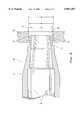
FIG. 1 shows a side view of a surgical drill guide according to the invention;
FIG. 2 is a cross-section, cutaway view of an expandable collet in a contracted position and a guide sleeve according to the invention;
FIG. 3 is an enlarged cross-section of the collet being inserted into a locking plate;
FIG. 4 is a further enlarged view of the front of the collet;
FIG. 5 is a cross-section of a drill guide assembly of the invention locked coaxially to a screw hole and aligned at an angle to the surface of a locking plate;
FIG. 5A is an expanded cross-section of the forward portion of the drill guide assembly of FIG. 3;
FIG. 6 is a cross-section of a drill guide assembly according to the invention locked coaxially to a screw hole extending perpendicularly to the surface of the locking plate;
FIG. 6A is an expanded cross-section of the forward portion of the drill guide assembly of FIG. 4;
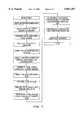
FIG. 7 is a flow chart of the method of implanting a cervical spine locking plate; and
FIG. 8 is a flow chart of the method for using the drill guide assembly to drill an aligned hole.
FIG. 1 shows an embodiment of a surgical drill guide assembly 8 according to the invention, which is adapted for use with a cervical spine locking plate. At a forward end of the drill guide assembly is acollet 10. Telescopically and slideably engaged withincollet 10 is aguide sleeve 12. Preferably, atissue protector 14 extends rearwardly from thesleeve 12. Thecollet 10,sleeve 12, andtissue protector 14 are adapted to axially receive adrill bit 16, and theguide sleeve 12 is sized to retain the spinningbit 16 in a precise coaxial alignment.
Thecollet 10 is fixed to a remote rear handle-member 18. Thehandle member 18 is pivotably attached to a scissor grip 20 by ahandle pin 22. Together, handlemember 18 and scissor grip 20 form a drill guide assembly handle 23, which allows a user to maneuver and use the drill guide assembly. The scissor grip 20 has anarm 24 that extends to the opposite side of thehandle pin 22 from the grip 20 to pivotably attach to anactuation bar 26 atactuation pin 28. An end of thebar 26 is pivotably attached with thesleeve 12 atsleeve pin 30.
Thus, the entire drill guide assembly in this embodiment forms a four bar linkage. When a surgeon squeezes scissor grip 20 towardshandle member 18, thearm 24 forces theactuation bar 26 forward. This in turn forces thesleeve 12 to slide forward, deeper intocollet 10. Preferably, however, no part of thesleeve 12 can slide further forward than the front of thecollet 10. The scissor grip 20 has aforward wall 32 and arear wall 34 to help the surgeon manually force thesleeve 12 forward or backward by closing or opening the guide sleeve assembly with only one hand. Preferably,leaf springs 36 are fastened to thehandle member 18 and the scissor grip 20 to further assist rearward motion of thesleeve 12 by biasing thehandle 23 towards an open position.
Thecollet 10 has aforward end 40 that is radially expandable. In this embodiment, the collet has a plurality offingers 38 that can be spread apart to expand theforward end 40 of thecollet 10.
Referring to FIG. 2, thecollet 10 coaxially receives thesleeve 12 about anaxis 37. Also, a guide bore 39 extends alongaxis 37 for guiding a drill bit coaxially therein.
Theforward end 40 ofcollet 10 is preferably comprised of longitudinally extendingfingers 38. Thefingers 38 are divided byslots 42 extending longitudinally betweenadjacent fingers 38. Thesefingers 38 are resiliently biased inwardly and naturally assume an inward disposition when in a relaxed state and when thesleeve 12 is in the unlocked position, as shown in the figure. In the figure, a portion of thesleeve 12 has been cut away to better illustrate theslots 42.
At a frontmost portion of the expandableforward end 40 of thecollet 10, thefingers 38 form a radially expandablecircumferential neck 44. At the back end of and adjacent toneck 44 is ashoulder 46, and at the front end of and adjacent toneck 44 are protrusions that form a radiallyexpandable rim 48. These portions of thecollet 10, i.e., theneck 44, theshoulder 46, and therim 44, are preferably a single piece of material of unitary construction, in the interest of minimizing the size of the drill guide that must be inserted into an incision.
In the contracted, unlocked position shown in FIG. 2, theneck 44 and therim 48 are sized to fit freely through screw holes in a locking plate. FIG. 3 shows thecollet 10 being inserted into ascrew hole 64 in a lockingplate 56. In the drawing, the collet is in its natural, contracted position. Thecollet 10 is resiliently biased towards this position, in which theneck 44 has a contracted diameter d1 and the rim has a contracted rim diameter d2. Thescrew hole 64 has an inner wall with a hole diameter d3.
The contracted rim diameter d2 is smaller than the hole diameter d3 to permit free and unfettered extraction of therim 48 from thehole 64. Preferably, the contracted rim diameter measures between 0.1 mm and 0.3 mm less than the hole diameter d3. More preferably, the rim diameter d2 is 0.2 mm smaller than the hole. The contracted rim diameter d2 is preferably between 4.2 mm and 4.4 mm in a drill guide that functions with a hole diameter d3 of about 4.5 mm. Thus, the contracted rim diameter is approximately 95% the size of the hole diameter. Also, the contracted rim diameter d2 is preferably about between 1 mm and 2 mm larger than the contracted neck diameter d1. Thus, therim 48 protrudes from theneck 44 by a preferred 1 mm. Hence, the contracted neck diameter d1 is preferably more than 95% as large as the contracted rim diameter d2.
These diameters permit a surgeon to extract, and most preferably also insert, therim 48 of thecollet 10 through ascrew hole 64 without therim 48 catching in thefar side 57 of theplate 56 when thecollet 10 is contracted. This arrangement virtually eliminates the possibility ofcollet 10 failing to disengage from abone plate 56, reducing the likelihood of unintentional extraction of temporary fixation pins or misalignment of a previously positionedplate 56.
At the same time, having arim 48, provides the surgeon with a detectable feel for when the rim has completely passed the through thehole 64. In alternative embodiments, therim 48 may be eliminated completely, for instance by reducing the contracted rim diameter d2 to an equal size as the contracted neck diameter d1. These embodiments, though, would lack the signal to the surgeon produced by full passage of therim 48 through thehole 64.
As shown in FIG. 4, to further foment free removal of therim 48 from thehole 64, therim 48 is rounded in a cross-section taken parallel toaxis 37. The cross section preferably curves around aradius 49 of about 0.15 mm. Also, in this embodiment, a surface of therim 48 disposed adjacent theneck 44 is configured at anangle 51 of less than 55° to theneck 44, and most preferably at about 45° thereto. In some embodiments, this angled surface is preferably joined to theneck 44 via a narrow surface 47 of concave radius.
Referring again to FIG. 3,shoulder 46 has a diameter d4 that is greater than the contracted rim diameter d2. Thus, theshoulder 46 has a diameter that is greater than the hole diameter d3 such that theshoulder 46 cannot be inserted therethrough. Still further, in the preferred embodiment, theneck 44 is slightly longer than the thickness of thehole wall 65, such that the neck can abut the wall of the locking plate hole and therim 48 can abut the inside surface of a lockingplate 56. In this manner, the drill guide assembly can be secured to the lockingplate 56, restricting relative movement.
The inside of the expandableforward end 40 thecollet 10 preferably has a variable inner diameter. Preferably, thefingers 38 have astep 50 or a taper, resulting in a smallerinner collet 10 diameter forward of thestep 50.
Theguide sleeve 12 includes aforward portion 52 that cooperates with thefingers 38 to expand thefingers 38 when theguide sleeve 12 is moved into a locked position. Preferably, theguide sleeve 12 is tapered attaper angle 53 to theaxis 37 to form aconical forward portion 52. Theconical section 52 ofguide sleeve 12 pushes outwardly against the inner surface of thecollet 10 as theguide sleeve 12 is moved forward to expand theforward end 40. In this embodiment, the conical section mates with and pushes against theinner collet 10 surface forward ofstep 50 to push thefingers 38 radially outward. When theguide sleeve 12 is in the unlocked position as shown in FIG. 2, theconical section 52 allows thefingers 38 to return to a relaxed, contracted position. This allows thecollet 10 to be inserted and retracted from the plate hole. Thetaper angle 53 is preferably between 3° and 5°, and more preferably about 4°. The inner surface of thecollet 10 forward of thestep 50 is also preferably tapered at an angle 55 toaxis 37 that is substantially equal to taperangle 53. This range of angles provides a desirable amount of movement of thesleeve 12 within thecollet 10 to bias thecollet 10 from a contracted position to an expanded position.
When the surgeon squeezes thehandle 23, theguide sleeve 12 is moved forward and theconical section 52 cooperatively forces the inner surface of thecollet 10 beyondstep 50 andfingers 38 radially outward. Thus, the forward motion of theguide sleeve 12 towards a forward position expands theforward end 40 of thecollet 10 to an expanded position. In this manner, theneck 44 can be expanded to abut the inner wall of the plate screw hole and therim 48 is expanded to abut the inner surface of the locking plate. In the expanded position, the expanded outer diameter d5 of therim 48 is greater than the plate hole diameter d3 so that the guide cannot be retracted from the plate hole, as shown in FIG. 6A.
FIGS. 5-6A show thesleeve 12 in a locked, forward position, and theexpandable end 40 in an expanded position and locked to different screw holes of the same predetermined diameter d3. Referring to FIGS. 5 and 5A, screwhole 54 in lockingplate 56 is disposed at an angle of about 12° to the locking plate's 56 outsidesurface 58. The drill guide assembly is configured so that when thecollet 10 is expanded, as shown, theneck 44 presses outwardly againstinterior wall 60 ofscrew hole 54, positively gripping thewall 60. Therim 48 preferably abuts the back surface of theplate 56 so that the neck positions the guide. Theshoulder 46, on the other hand, preferably does not abut theoutside surface 58 of theplate 56. A firm locking against theplate 56 results, and precise co-axial alignment through the center ofscrew hole 54 is achieved even though the surface area ofwall 60 is small. In this embodiment, the axis of the drill guide is aligned with the axis of theplate screw hole 54. Thus, the axis of the hole drilled into the bone will also be aligned with the axis of theplate screw hole 54. In this manner, an anchoring screw inserted into the drilled hole will be centered and aligned with theplate screw hole 54, i.e., they too will be substantially co-axially aligned.
Theplate 56 and the guide may become slippery during use when blood and drilled tissue residue cover the instruments. In this situation, rim 48 aids in preventing thecollet 10 from sliding backwards, out of thehole 54. Therim 48 is adapted to rest against the far side of theplate 56, near the perimeter of thehole 54. Note that when the drill guide of this embodiment is locked to anangled hole 54, as shown, only a segment ofrim 48 may actually contact the back of theplate 56. This small contact surface suffices to retain thecollet 10 within thehole 54.
Preferably, agap 62 remains between the forwardly facing surface ofshoulder 46 and theplate 56. This is because, in the preferred embodiment, theshoulder 46 is not necessary for achieving a proper drill alignment or a secure locking. Consequentially, a surgeon need not press the drill guide against the lockingplate 56 to keep the guide properly seated within thehole 54.
FIGS. 6 and 6A show the same embodiment of the invention locked to ascrew hole 64 in a different part of lockingplate 56.Hole 64 is perpendicular to the locking plate's 56surface 66. In this application, most of therim 48 is in contact with the back ofplate 56. Similarly to the applications shown in FIGS. 5 and 5A, agap 62 preferably remains between the forwardly facing surface ofshoulder 46 and theplate 56.
As seen in FIGS. 5 and 6, the internal diameter of thetissue protector 14 is preferably wider than that of thesleeve 12, forming astep 68. Thisstep 68 may alternatively be formed in a different place along the length of thetissue protector 14 or thesleeve 12.Step 68 is adapted to stop asurgical drill bit 16 that is inserted through the rearward end of the tissue protector from advancing beyond a predetermined depth. This stopping action occurs when thestep 68 contacts aportion 70 of thedrill 16 that is wider than the internal diameter of thesleeve 12 or thetissue protector 14 forward of thestep 68, as illustrated in FIG. 6.
Referring again to FIG. 1, thedrill bit 16 illustrated has asafety stop 72 with a wider diameter than the interior of thetissue protector 14. The rear 72 of thetissue protector 14 also preferably prevents advancement of thedrill bit 16 when the tissue-protector rear 74 contacts the bit's 16safety stop 72. By selecting abit 16 with an appropriately locatedsafety stop 72 orsafety step 68, the surgeon is assured that thebit 16 will penetrate the vertebral body no further than necessary for insertion of a screw.
The flow chart in FIG. 7 provides the procedure for implanting a cervical spine locking plate. After making an incision, and measuring the cervical vertebra to be fixed with the plate, a surgeon places a cervical locking plate of a correct estimated length on the vertebral body. The surgeon then bends the plate to contour it to the correct lordotic curvature. Once the plate is properly positioned on the vertebra, it is secured with a temporary fixation pin, which is monitored under lateral imaging. The surgeon then locks the drill guide to the plate and drills into the bone. He or she then taps the hole, inserts an anchor screw, and inserts a locking screw to lock the anchor screw to the plate. The locking and drilling process is repeated for the remaining screws. The last hole is drilled through the plate hole in which the locking pin was located. Finally, the surgeon closes the wound.
The chart in FIG. 8 shows the procedure for using the drill guide. A surgeon inserts the collet into the plate screw hole and squeezes the handle to slide the sleeve forward, expanding the collet with the conical portion of the sleeve and locking the drill guide to the plate. The surgeon then inserts the drill through the drill guide sleeve, drills the hole, and removes the drill. He or she opens the handle of the drill guide, sliding the sleeve backwards and releasing the collet from the hole, and then freely and unfetteredly removes the guide from the plate.
Before and during locking-plate implantation, the surgeon may insert theexpandable end 40 of thecollet 10 into a screw hole in a lockingplate 56. By squeezing thehandle 23, the surgeon may grasp and manipulate theplate 56 without an additional plate holder if he or she so desires.
Preferably, friction between the forwardly movedconical portion 52 and the inner surface offingers 38 beyondstep 50 retains theexpandable end 40 of thecollet 10 in an expanded, locked position. This provides a presently preferred travel of scissor grip 20 required to expand and contract thecollet 10. In this embodiment, the inward bias offingers 38 is selected to produce the desired friction, while allowing operation of thehandle 23 with only one hand. Alternative taper angles ofconical portion 52 andinner finger 38 surfaces, andalternative finger 38 resiliencies may be chosen according to the purposes of other embodiments.
Thetissue protector 14 is preferably sized so that once theplate 56 is properly positioned over the implantation site and thecollet 10 is locked to the plate, thetissue protector 14 extends to the outside of the patient's body. As a result, a spinningbit 16 will not laterally reach or harm surrounding tissues that the surgeon does not intend to drill.
Also, thehandle 23 is preferably located remotely from the drilling site. This frees space near theplate 56 and permits insertion of the drill guide into narrow incisions.
Various changes to the above description are possible without departing from the scope of the invention. For example, in embodiments for use with plates that have noncircular screw holes, the outer cross-section ofcollet 10 may match the shape of the holes. It is intended that the following claims cover all modifications and embodiments that fall within the true spirit and scope of the present invention.
Claims (21)
1. Instrumentation for osteofixation comprising:
a bone plate with plate hole for receiving a bone fastener and having an inner wall; and
a surgical drill guide comprising guide member, for guiding a drill bit, and a hollow collet disposed substantially coaxially with the guide member and having a radially expandable forward end with a radially expandable neck and an outwardly projecting rim disposed forward of the neck, the rim being configured and dimensioned such that it is freely extractable through the plate hole in a contracted collet position and impassable through the plate hole in an expanded collet position, the neck being configured and dimensioned for pressing outwardly against an inner wall of the plate hole in the expanded collet position for releasibly securing the drill guide to the plate.
2. The instrumentation of claim 1, wherein the plate hole has a preselected hole diameter, and the rim defines an outer rim diameter that is smaller than the hole diameter in the contracted collet position and larger than the hole diameter in the expanded collet position.
3. The instrumentation of claim 2, wherein the collet forward end comprises a plurality of longitudinally extending fingers that define the neck and rim and that are biased radially outwardly when the guide sleeve is moved into a forward position.
4. The instrumentation of claim 2, wherein the neck and rim have an axis and the rim has a rounded cross section in a plane extending through the axis for preventing the rim from catching on the plate during extraction of the rim from the plate hole.
5. The instrumentation of claim 4, wherein the rounded cross-section of the rim has a radius of about 0.15 mm.
6. The instrumentation of claim 2, wherein the rim has a surface substantially adjacent the neck and configured at a first angle thereto of less than about 55°.
7. The instrumentation of claim 6, wherein the first angle is about 45°.
8. The instrumentation of claim 1, wherein the guide member comprises a guide sleeve disposed movably axially and telescopically within the collet and defining a guide bore for axially receiving and guiding a drill bit, the guide sleeve having a first position within the collet in which the sleeve biases the collet towards the expanded collet position.
9. The instrumentation of claim 8, wherein the sleeve has a surface tapered inwardly at a second angle of between 3° and 5° for cooperatively biasing the collet towards the expanded collet position when the collet is moved forward therein.
10. The instrumentation of claim 9, wherein the second angle is about 4°.
11. Instrumentation for osteofixation comprising:
a bone plate with plate hole for receiving a bone fastener and having an inner wall of a preselected hole diameter; and
a surgical drill guide comprising guide member, for guiding a drill bit, and a hollow collet disposed substantially coaxially with the guide member and having a radially expandable forward end with a radially expandable neck and an outwardly projecting rim disposed forward of the neck, the rim defining a contracted outer rim diameter that is smaller than the hole diameter in an contracted collet position and an expanded outer rim diameter that is larger than the hole diameter in an expanded collet position such that the rim is freely extractable through the plate hole in the contracted collet position and impassable through the plate hole in the expanded collet position, the neck being configured and dimensioned for pressing outwardly against an inner wall of the plate hole in the expanded collet position for releasibly securing the drill guide to the plate.
12. The instrumentation of claim 11, wherein the contracted rim diameter is at least about 0.1 mm smaller than the hole diameter.
13. The instrumentation of claim 12, wherein the contracted rim diameter is no more than about 0.3 mm smaller than the hole diameter.
14. The instrumentation of claim 13, wherein the contracted rim diameter is about 0.2 mm smaller than the hole diameter.
15. The instrumentation of claim 11, wherein the contracted rim diameter is about 95% of the hole diameter.
16. The instrumentation of claim 11, wherein the rim protrudes radially from the neck by less than about 0.1 mm.
17. The instrumentation of claim 16, wherein the neck has a contracted neck diameter in the contracted collet position, the contracted rim diameter being equal to the contracted neck diameter.
18. The instrumentation of claim 11, wherein the neck has a diameter when the neck is in the contracted collet position that is at least about 95% as large as the contracted rim diameter.
19. The instrumentation of claim 11, wherein the collet is configured for naturally and resiliently biasing the rim to the contracted collet position.
20. The instrumentation of claim 11, wherein the collet comprises a shoulder having a diameter larger than the hole diameter, the shoulder, neck, and rim being a single piece of unitary construction.
21. Instrumentation for osteofixation comprising:
a locking bone plate with a plurality of plate holes for receiving a an anchor screw therethrough and having an inner wall of a preselected hole diameter; and
a surgical drill guide comprising guide member, for guiding a drill bit, and a hollow collet disposed substantially coaxially with the guide member and having a radially expandable forward end with a radially expandable neck and an outwardly projecting rim disposed forward of the neck, the rim defining a contracted outer rim diameter that is smaller than the hole diameter in an contracted collet position and an expanded outer rim diameter that is larger than the hole diameter in an expanded collet position such that the rim is freely extractable through the plate hole in the contracted collet position and unreceivable through the plate hole in the expanded collet position, the neck being configured and dimensioned for pressing outwardly against an inner wall of the plate hole in the expanded collet position for releasibly securing the drill guide to the plate hole in precise alignment therewith.
Priority Applications (11)
| Application Number | Priority Date | Filing Date | Title |
|---|---|---|---|
| US08/886,547US5851207A (en) | 1997-07-01 | 1997-07-01 | Freely separable surgical drill guide and plate |
| ZA985284AZA985284B (en) | 1997-07-01 | 1998-06-18 | Freely separable surgical drill guide and plate |
| DE69823030TDE69823030T2 (en) | 1997-07-01 | 1998-06-20 | FREE SEPARABLE SURGICAL PIPE AND PLATE |
| ES98937525TES2215316T3 (en) | 1997-07-01 | 1998-06-20 | DRILLING GUIDE AND SURGICAL PLATE CAN BE FREELY SEPARATED. |
| AU86285/98AAU719525B2 (en) | 1997-07-01 | 1998-06-20 | Freely separable surgical drill guide and plate |
| AT98937525TATE263510T1 (en) | 1997-07-01 | 1998-06-20 | FREELY SEPARABLE SURGICAL DRILL GUIDE AND PLATE |
| JP50624299AJP3996211B2 (en) | 1997-07-01 | 1998-06-20 | Freely splittable surgical drilling guide and plate |
| CNB98806748XACN1155341C (en) | 1997-07-01 | 1998-06-20 | Freely separable surgical drill guide and plate |
| EP98937525AEP0993275B1 (en) | 1997-07-01 | 1998-06-20 | Freely separable surgical drill guide and plate |
| PCT/EP1998/003778WO1999001072A1 (en) | 1997-07-01 | 1998-06-20 | Freely separable surgical drill guide and plate |
| US09/686,198USRE38684E1 (en) | 1997-07-01 | 2000-10-10 | Freely separable surgical drill guide and plate |
Applications Claiming Priority (1)
| Application Number | Priority Date | Filing Date | Title |
|---|---|---|---|
| US08/886,547US5851207A (en) | 1997-07-01 | 1997-07-01 | Freely separable surgical drill guide and plate |
Related Child Applications (1)
| Application Number | Title | Priority Date | Filing Date |
|---|---|---|---|
| US09/686,198ReissueUSRE38684E1 (en) | 1997-07-01 | 2000-10-10 | Freely separable surgical drill guide and plate |
Publications (1)
| Publication Number | Publication Date |
|---|---|
| US5851207Atrue US5851207A (en) | 1998-12-22 |
Family
ID=25389237
Family Applications (2)
| Application Number | Title | Priority Date | Filing Date |
|---|---|---|---|
| US08/886,547CeasedUS5851207A (en) | 1997-07-01 | 1997-07-01 | Freely separable surgical drill guide and plate |
| US09/686,198Expired - LifetimeUSRE38684E1 (en) | 1997-07-01 | 2000-10-10 | Freely separable surgical drill guide and plate |
Family Applications After (1)
| Application Number | Title | Priority Date | Filing Date |
|---|---|---|---|
| US09/686,198Expired - LifetimeUSRE38684E1 (en) | 1997-07-01 | 2000-10-10 | Freely separable surgical drill guide and plate |
Country Status (10)
| Country | Link |
|---|---|
| US (2) | US5851207A (en) |
| EP (1) | EP0993275B1 (en) |
| JP (1) | JP3996211B2 (en) |
| CN (1) | CN1155341C (en) |
| AT (1) | ATE263510T1 (en) |
| AU (1) | AU719525B2 (en) |
| DE (1) | DE69823030T2 (en) |
| ES (1) | ES2215316T3 (en) |
| WO (1) | WO1999001072A1 (en) |
| ZA (1) | ZA985284B (en) |
Cited By (148)
| Publication number | Priority date | Publication date | Assignee | Title |
|---|---|---|---|---|
| US6210415B1 (en)* | 2000-02-18 | 2001-04-03 | Lab Engineering & Manufacturing, Inc. | Surgical drill guide |
| WO2001082805A1 (en)* | 2000-04-28 | 2001-11-08 | Synthes Ag Chur | Remotely aligned surgical drill guide |
| WO2001082804A1 (en) | 2000-04-28 | 2001-11-08 | Synthes Ag Chur | Dual drill guide for a locking bone plate |
| US20020120273A1 (en)* | 1999-10-13 | 2002-08-29 | Needham Dusty Anna | Anterior cervical plating system and method |
| US20020123668A1 (en)* | 2001-01-29 | 2002-09-05 | Stephen Ritland | Retractor and method for spinal pedicle screw placement |
| WO2003007826A1 (en)* | 2001-07-17 | 2003-01-30 | Sdgi Holdings, Inc, | System and method for securing a plate to the spinal column |
| US20030187443A1 (en)* | 2002-03-27 | 2003-10-02 | Carl Lauryssen | Anterior bone plate system and method of use |
| US20040015174A1 (en)* | 2002-07-22 | 2004-01-22 | Null William B. | Guide assembly for engaging a bone plate to a bony segment |
| US20040039387A1 (en)* | 2002-08-22 | 2004-02-26 | Larry Gause | System for stabilizing a portion of the spine |
| US6699253B2 (en) | 2000-09-22 | 2004-03-02 | Codman & Shurtleff, Inc | Self centering bone drill |
| US20040092947A1 (en)* | 2002-09-30 | 2004-05-13 | Foley Kevin T. | Devices and methods for securing a bone plate to a bony segment |
| US20040127904A1 (en)* | 2002-12-31 | 2004-07-01 | Konieczynski David D. | Bone plate and resilient screw system allowing bi-directional assembly |
| US20040152955A1 (en)* | 2003-02-04 | 2004-08-05 | Mcginley Shawn E. | Guidance system for rotary surgical instrument |
| US20040158246A1 (en)* | 1998-04-30 | 2004-08-12 | Sofamor S.N.C. | Anterior implant for the spine |
| US20040171930A1 (en)* | 2003-02-04 | 2004-09-02 | Zimmer Technology, Inc. | Guidance system for rotary surgical instrument |
| US20040186482A1 (en)* | 2003-03-21 | 2004-09-23 | Kolb Eric D. | Modular drill guide |
| US20040204716A1 (en)* | 2003-04-09 | 2004-10-14 | Jonathan Fanger | Drill guide with alignment feature |
| US20040210232A1 (en)* | 2003-04-09 | 2004-10-21 | Tushar Patel | Guide device and plate inserter |
| US20040220571A1 (en)* | 1998-04-30 | 2004-11-04 | Richard Assaker | Bone plate assembly |
| US20040267274A1 (en)* | 2003-06-27 | 2004-12-30 | Tushar Patel | Tissue retractor and drill guide |
| US20050004577A1 (en)* | 2002-01-09 | 2005-01-06 | Dankward Hontzsch | Device for drilling or for inserting implants |
| US20050015089A1 (en)* | 2003-03-26 | 2005-01-20 | Young Robert Allan | Locking bone plate |
| US20050059975A1 (en)* | 2003-09-17 | 2005-03-17 | Jonathan Fanger | Variable depth drill with self-centering sleeve |
| WO2005016128A3 (en)* | 2003-08-13 | 2005-06-09 | Lawrence J Binder Jr | Quick-release drill guide assembly for bone plate |
| US20050131419A1 (en)* | 2003-12-16 | 2005-06-16 | Mccord David | Pivoting implant holder |
| US20050131420A1 (en)* | 2003-12-16 | 2005-06-16 | Techiera Richard C. | Pivoting implant holder |
| US6913463B2 (en) | 2002-02-20 | 2005-07-05 | Gordon D. Blacklock | Drilling guide for dental implantation |
| US20050177153A1 (en)* | 2001-06-27 | 2005-08-11 | Guzman Pamela C. | Minimally invasive orthopaedic apparatus and methods |
| US6929606B2 (en) | 2001-01-29 | 2005-08-16 | Depuy Spine, Inc. | Retractor and method for spinal pedicle screw placement |
| WO2005099593A1 (en)* | 2004-04-12 | 2005-10-27 | Synthes (Usa) | Free hand drill guide |
| US20050251138A1 (en)* | 2003-10-20 | 2005-11-10 | Olevsky Boris | Bone plate and method for using bone plate |
| US6966910B2 (en) | 2002-04-05 | 2005-11-22 | Stephen Ritland | Dynamic fixation device and method of use |
| US7008431B2 (en) | 2001-10-30 | 2006-03-07 | Depuy Spine, Inc. | Configured and sized cannula |
| US20060058585A1 (en)* | 2003-03-06 | 2006-03-16 | Martin Oberlaender | Medical instrument set and method for creating a surgical operating space in operations on the jaw |
| US20060106387A1 (en)* | 2004-11-16 | 2006-05-18 | Depuy Spine, Inc. | Spinal plate system and method of use |
| US20060106398A1 (en)* | 2004-11-18 | 2006-05-18 | Carl Lauryssen | Cervical bone preparation tool and implant guide systems |
| US20060106399A1 (en)* | 2004-11-18 | 2006-05-18 | Taras John S | Drill guide tissue protector |
| US20060122602A1 (en)* | 2004-12-08 | 2006-06-08 | Depuy Spine, Inc. | Hybrid spinal plates |
| US20060122607A1 (en)* | 2004-12-08 | 2006-06-08 | Depuy Spine, Inc. | Spinal plate and drill guide |
| US20060149250A1 (en)* | 2004-12-14 | 2006-07-06 | Castaneda Javier E | Bone plate with pre-assembled drill guide tips |
| US20060155283A1 (en)* | 2005-01-07 | 2006-07-13 | Depuy Spine Sarl | Occipital plate and guide systems |
| US20060161158A1 (en)* | 2004-12-14 | 2006-07-20 | Orbay Jorge L | Bone fracture fixation plate shaping system |
| US7081119B2 (en) | 2003-08-01 | 2006-07-25 | Hfsc Company | Drill guide assembly for a bone fixation device |
| US20060189997A1 (en)* | 2005-02-10 | 2006-08-24 | Zimmer Spine, Inc. | All through one drill guide for cervical plating |
| US20060190001A1 (en)* | 2004-05-19 | 2006-08-24 | Sean Powell | Snap-lock for drill sleeve |
| US20060257817A1 (en)* | 2005-05-12 | 2006-11-16 | Robert Shelton | Dental implant placement locator and method of use |
| US20060264946A1 (en)* | 2003-03-26 | 2006-11-23 | Young Robert A | Locking bone plate |
| EP1728479A1 (en)* | 2005-06-01 | 2006-12-06 | Stryker Trauma SA | Quick-release guide for elements of a fixation system external to bone |
| US20070016189A1 (en)* | 2005-06-30 | 2007-01-18 | Depuy Spine Sarl | Orthopedic clamping hook assembly |
| US7166073B2 (en) | 2000-09-29 | 2007-01-23 | Stephen Ritland | Method and device for microsurgical intermuscular spinal surgery |
| USD536453S1 (en) | 2004-03-25 | 2007-02-06 | Precimed S.A. | Bone plate |
| US7175624B2 (en) | 2002-12-31 | 2007-02-13 | Depuy Spine, Inc. | Bone plate and screw system allowing bi-directional assembly |
| US20070055286A1 (en)* | 2001-10-31 | 2007-03-08 | Ralph James D | Polyaxial drill guide |
| WO2007041638A1 (en)* | 2005-10-03 | 2007-04-12 | Synthes (Usa) | Bone plate with captive clips |
| US20070088365A1 (en)* | 2005-09-29 | 2007-04-19 | Ruhling Marc E | Orthopaedic gage, kit and associated method |
| US20070088364A1 (en)* | 2005-09-29 | 2007-04-19 | Ruhling Marc E | Trauma gage, kit and associated method |
| US7207992B2 (en) | 2001-09-28 | 2007-04-24 | Stephen Ritland | Connection rod for screw or hook polyaxial system and method of use |
| US20070093848A1 (en)* | 2005-09-29 | 2007-04-26 | Peter Harris | Cervical drill guide apparatus |
| US7214186B2 (en) | 2000-09-29 | 2007-05-08 | Stephen Ritland | Method and device for retractor for microsurgical intermuscular lumbar arthrodesis |
| US20070162013A1 (en)* | 2005-12-09 | 2007-07-12 | Depuy Spine, Inc. | Spinal plate and drill guide |
| US20070233112A1 (en)* | 2006-03-20 | 2007-10-04 | Orbay Jorge L | Method of Bone Plate Shaping |
| US20070233108A1 (en)* | 2006-03-15 | 2007-10-04 | Stalcup Gregory C | Spine fixation device |
| US20070239153A1 (en)* | 2006-02-22 | 2007-10-11 | Hodorek Robert A | Computer assisted surgery system using alternative energy technology |
| US20070244489A1 (en)* | 2003-06-27 | 2007-10-18 | Tushar Patel | Tissue retractor and guide device |
| US20070274905A1 (en)* | 2006-05-24 | 2007-11-29 | Water To Gas Lp | Thermal disassociation of water |
| US20080009678A1 (en)* | 2006-07-08 | 2008-01-10 | Stephen Ritland | Pedicle Seeker and Retractor, and Methods of Use |
| US20080045960A1 (en)* | 2004-03-25 | 2008-02-21 | Bruecker Kenneth | Locking tpo plate and method of use |
| US7341591B2 (en) | 2003-01-30 | 2008-03-11 | Depuy Spine, Inc. | Anterior buttress staple |
| US20080077152A1 (en)* | 2006-09-26 | 2008-03-27 | K2M, Inc. | Cervical drill guide apparatus |
| US20080082102A1 (en)* | 2003-03-26 | 2008-04-03 | Bruecker Kenneth | Locking tpo plate and method of use |
| US20080103595A1 (en)* | 2005-02-25 | 2008-05-01 | Precimed S.A. of Geneva, CH | Device and template for canine humeral slide osteotomy |
| US20080132900A1 (en)* | 2006-11-13 | 2008-06-05 | Stryker Trauma Gmbh | Drill alignment assembly for a bone plate using tissue protection sleeves that are fixed in the bone plate |
| US7416553B2 (en) | 2003-04-09 | 2008-08-26 | Depuy Acromed, Inc. | Drill guide and plate inserter |
| US7425213B2 (en) | 2002-12-10 | 2008-09-16 | Depuy Products, Inc. | Method of endosteal nailing |
| US20080287957A1 (en)* | 2007-05-18 | 2008-11-20 | Depuy Spine, Inc. | Insertion blade assembly and method of use |
| US7455639B2 (en) | 2004-09-20 | 2008-11-25 | Stephen Ritland | Opposing parallel bladed retractor and method of use |
| US20090024132A1 (en)* | 2007-07-19 | 2009-01-22 | Spinal Elements, Inc. | Attachable instrument guide with detachable handle |
| US20090076556A1 (en)* | 2006-02-08 | 2009-03-19 | Synthes Usa | Transbuccal plate holding cannula |
| US20090088604A1 (en)* | 2007-09-28 | 2009-04-02 | David Lowry | Vertebrally-mounted tissue retractor and method for use in spinal surgery |
| US7527639B2 (en) | 2000-02-01 | 2009-05-05 | Depuy Products, Inc. | Fixation system with multidirectional bone supports |
| US20090143716A1 (en)* | 2007-11-27 | 2009-06-04 | David Lowry | Methods and systems for repairing an intervertebral disc using a transcorporal approach |
| US20090157086A1 (en)* | 2007-12-17 | 2009-06-18 | Stryker Leibinger Gmbh & Co. Kg | Bone plate instrument and method |
| US7563263B2 (en) | 2000-02-01 | 2009-07-21 | Depuy Products, Inc. | Intramedullary fixation device for metaphyseal long bone fractures |
| US20090204121A1 (en)* | 2008-02-13 | 2009-08-13 | Cesare Cavallazzi | Drill Sleeve |
| US20090254130A1 (en)* | 2008-04-08 | 2009-10-08 | Wotton Iii Harold M | Bone clamp |
| US7625375B2 (en) | 2003-08-06 | 2009-12-01 | Warsaw Orthopedic, Inc. | Systems and techniques for stabilizing the spine and placing stabilization systems |
| US20090318979A1 (en)* | 2008-06-20 | 2009-12-24 | Osteomed L.P. | Locking Plate Benders |
| US7655025B2 (en) | 2001-09-28 | 2010-02-02 | Stephen Ritland | Adjustable rod and connector device and method of use |
| US7666185B2 (en) | 2003-09-03 | 2010-02-23 | Synthes Usa, Llc | Translatable carriage fixation system |
| EP2158863A1 (en) | 2008-09-02 | 2010-03-03 | Stryker Trauma AG | Locking screw with synchronized thread |
| US7682375B2 (en) | 2002-05-08 | 2010-03-23 | Stephen Ritland | Dynamic fixation device and method of use |
| US7695502B2 (en) | 2000-02-01 | 2010-04-13 | Depuy Products, Inc. | Bone stabilization system including plate having fixed-angle holes together with unidirectional locking screws and surgeon-directed locking screws |
| US20100130983A1 (en)* | 2008-11-26 | 2010-05-27 | Osteomed L.P. | Drill Guide for Angled Trajectories |
| US7727264B2 (en) | 2000-02-01 | 2010-06-01 | Depuy Products, Inc. | Intramedullary fixation device for metaphyseal long bone fractures |
| US7731721B2 (en) | 2003-07-16 | 2010-06-08 | Synthes Usa, Llc | Plating system with multiple function drill guide |
| US20100152793A1 (en)* | 2007-09-13 | 2010-06-17 | David Lowry | Transcorporeal spinal decompression and repair systems and related methods |
| US7753939B2 (en) | 2000-06-30 | 2010-07-13 | Stephen Ritland | Polyaxial connection device and method |
| US7763047B2 (en) | 2002-02-20 | 2010-07-27 | Stephen Ritland | Pedicle screw connector apparatus and method |
| US7776047B2 (en) | 2003-04-09 | 2010-08-17 | Depuy Spine, Inc. | Guide for spinal tools, implants, and devices |
| US20100217399A1 (en)* | 2009-02-22 | 2010-08-26 | Groh Gordon I | Base plate system for shoulder arthroplasty and method of using the same |
| US20100262153A1 (en)* | 2009-04-10 | 2010-10-14 | Millett Peter J | Parallel drill guide |
| US7824410B2 (en) | 2001-10-30 | 2010-11-02 | Depuy Spine, Inc. | Instruments and methods for minimally invasive spine surgery |
| US7857838B2 (en) | 2003-03-27 | 2010-12-28 | Depuy Products, Inc. | Anatomical distal radius fracture fixation plate |
| US7867279B2 (en) | 2006-01-23 | 2011-01-11 | Depuy Spine, Inc. | Intervertebral disc prosthesis |
| US7881770B2 (en)* | 2000-03-01 | 2011-02-01 | Medtronic Navigation, Inc. | Multiple cannula image guided tool for image guided procedures |
| US7887595B1 (en) | 2005-12-05 | 2011-02-15 | Nuvasive, Inc. | Methods and apparatus for spinal fusion |
| US7905909B2 (en) | 2005-09-19 | 2011-03-15 | Depuy Products, Inc. | Bone stabilization system including multi-directional threaded fixation element |
| US7909843B2 (en) | 2004-06-30 | 2011-03-22 | Thompson Surgical Instruments, Inc. | Elongateable surgical port and dilator |
| US7914561B2 (en) | 2002-12-31 | 2011-03-29 | Depuy Spine, Inc. | Resilient bone plate and screw system allowing bi-directional assembly |
| US7935126B2 (en) | 2006-03-20 | 2011-05-03 | Depuy Products, Inc. | Bone plate shaping system |
| USRE42525E1 (en) | 1999-03-12 | 2011-07-05 | Depuy Spine, Inc. | Cannula and sizing insertion method |
| US8021399B2 (en) | 2005-07-19 | 2011-09-20 | Stephen Ritland | Rod extension for extending fusion construct |
| US8100955B2 (en) | 2005-03-17 | 2012-01-24 | Spinal Elements, Inc. | Orthopedic expansion fastener |
| US8114162B1 (en) | 2006-08-09 | 2012-02-14 | Nuvasive, Inc. | Spinal fusion implant and related methods |
| US8123757B2 (en) | 2003-12-31 | 2012-02-28 | Depuy Spine, Inc. | Inserter instrument and implant clip |
| US20120150186A1 (en)* | 2007-08-16 | 2012-06-14 | Nutek Orthopaedics, Inc. | External fixation apparatus with angularly adjustable drill guiding and pin clamping means |
| US8262571B2 (en) | 2003-05-22 | 2012-09-11 | Stephen Ritland | Intermuscular guide for retractor insertion and method of use |
| US8323292B2 (en) | 2008-12-15 | 2012-12-04 | Spinecore, Inc. | Adjustable pin drill guide and methods therefor |
| US8323320B2 (en) | 2007-09-13 | 2012-12-04 | Transcorp, Inc. | Transcorporeal spinal decompression and repair system and related method |
| US8419741B2 (en) | 2000-03-17 | 2013-04-16 | Kinamed, Inc. | Marking template for installing a custom replacement device for resurfacing a femur and associated installation method |
| US8425569B2 (en) | 2010-05-19 | 2013-04-23 | Transcorp, Inc. | Implantable vertebral frame systems and related methods for spinal repair |
| US8652183B1 (en)* | 2009-07-07 | 2014-02-18 | Mari S Truman | Multi-angle orthopedic expansion head fastener |
| US8709054B2 (en) | 2007-08-07 | 2014-04-29 | Transcorp, Inc. | Implantable vertebral frame systems and related methods for spinal repair |
| USD708747S1 (en) | 2006-09-25 | 2014-07-08 | Nuvasive, Inc. | Spinal fusion implant |
| US8906033B2 (en) | 2009-03-30 | 2014-12-09 | DePuy Synthes Products, LLC | Cervical motion disc inserter |
| US20150018835A1 (en)* | 2012-01-26 | 2015-01-15 | Smith & Nephew, Inc. | Implant fixation member holder |
| US8986354B2 (en) | 2012-02-14 | 2015-03-24 | Zavation Llc | Surgical kit for spinal surgery |
| US9050151B2 (en) | 2012-03-06 | 2015-06-09 | Stryker Trauma Sa | Bone plate and aiming block |
| US9168153B2 (en) | 2011-06-16 | 2015-10-27 | Smith & Nephew, Inc. | Surgical alignment using references |
| US9220547B2 (en) | 2009-03-27 | 2015-12-29 | Spinal Elements, Inc. | Flanged interbody fusion device |
| US20160310180A1 (en)* | 2015-04-24 | 2016-10-27 | Meditech Spine, Llc | Anterior spinal bone plate holding system and method |
| US9750512B2 (en) | 2013-10-21 | 2017-09-05 | Zimmer Spine, Inc. | Drill guide for installing a bone plate |
| EP3284442A3 (en)* | 2016-07-27 | 2018-06-20 | Catalyst OrthoScience Inc. | Stabilized drill guide |
| US20190015088A1 (en)* | 2017-07-13 | 2019-01-17 | Medtronic Vascular, Inc. | Collapsible dilator |
| US10327787B2 (en) | 2015-12-28 | 2019-06-25 | Nuvasive, Inc | Adjustable depth drill guide |
| EP3552562A1 (en)* | 2018-04-11 | 2019-10-16 | Globus Medical, Inc. | Method and apparatus for locking a drill guide in a polyaxial hole |
| US10758361B2 (en) | 2015-01-27 | 2020-09-01 | Spinal Elements, Inc. | Facet joint implant |
| US10973646B2 (en) | 2013-03-11 | 2021-04-13 | Catalyst Orthoscience Inc. | Stabilized drill guide |
| US11007064B2 (en) | 2015-08-10 | 2021-05-18 | Catalyst Orthoscience Inc. | Arthroplasty prostheses with multi-axis fixation |
| US11007063B2 (en) | 2013-03-11 | 2021-05-18 | Catalyst Orthoscience Inc. | Offset reamers |
| WO2021133926A1 (en)* | 2019-12-27 | 2021-07-01 | Blue Fury Consulting, Llc | Anti-skive bone drill |
| US11058437B2 (en) | 2018-03-29 | 2021-07-13 | Zimmer Biomet Spine, Inc. | Systems and methods for pedicle screw implantation using flexible drill bit |
| US11123117B1 (en) | 2011-11-01 | 2021-09-21 | Nuvasive, Inc. | Surgical fixation system and related methods |
| US11382769B2 (en) | 2018-09-20 | 2022-07-12 | Spinal Elements, Inc. | Spinal implant device |
| US20220226004A1 (en)* | 2021-01-15 | 2022-07-21 | DePuy Synthes Products, Inc. | Self-orienting drill sleeve |
| US20240016528A1 (en)* | 2022-07-13 | 2024-01-18 | Globus Medical, Inc. | Plate inserter system and method |
| US11911284B2 (en) | 2020-11-19 | 2024-02-27 | Spinal Elements, Inc. | Curved expandable interbody devices and deployment tools |
| US12279969B2 (en) | 2020-12-17 | 2025-04-22 | Spinal Elements, Inc. | Spinal implant device |
Families Citing this family (10)
| Publication number | Priority date | Publication date | Assignee | Title |
|---|---|---|---|---|
| US7488326B2 (en)* | 2004-01-02 | 2009-02-10 | Zimmer Technology, Inc. | Combination targeting guide and driver instrument for use in orthopaedic surgical procedures |
| ES2346670T3 (en)* | 2005-08-15 | 2010-10-19 | Synthes Gmbh | OSTEOSYNTHESIS DEVICE. |
| WO2007130699A2 (en)* | 2006-01-13 | 2007-11-15 | Clifford Tribus | Spine reduction and stabilization device |
| US8425573B2 (en) | 2008-10-24 | 2013-04-23 | The Cleveland Clinic Foundation | Method and system for attaching a plate to a bone |
| CN102188273B (en)* | 2010-03-02 | 2013-03-27 | 上海微创骨科医疗科技有限公司 | Limit adjusting device |
| JP6046396B2 (en)* | 2012-07-02 | 2016-12-14 | 富士重工業株式会社 | Drill driving device and drill driving method |
| DE102013104887B4 (en)* | 2013-05-13 | 2021-03-18 | Aap Implantate Ag | Osteosynthesis plate and segment for an osteosynthesis plate |
| US10064668B2 (en)* | 2015-02-13 | 2018-09-04 | Kls-Martin, L.P. | Bone plate locking cannula and drill guide assembly |
| US9931702B2 (en)* | 2016-09-01 | 2018-04-03 | The Boeing Company | Locking drill bushing |
| CN117137602A (en)* | 2023-08-15 | 2023-12-01 | 上海三友医疗器械股份有限公司 | Cervical bone plate and plate guide for ACAF surgery |
Citations (24)
| Publication number | Priority date | Publication date | Assignee | Title |
|---|---|---|---|---|
| US1831813A (en)* | 1928-07-02 | 1931-11-17 | Independent Pneumatic Tool Co | Attachment for drills |
| US2248054A (en)* | 1939-06-07 | 1941-07-08 | Becker Joseph | Screw driver |
| US2490364A (en)* | 1948-02-27 | 1949-12-06 | Herman H Livingston | Bone pin |
| US2494229A (en)* | 1946-07-08 | 1950-01-10 | John G Collison | Bone surgery |
| US2839953A (en)* | 1955-10-24 | 1958-06-24 | Boeing Co | Drill motor collet mounts |
| US2935905A (en)* | 1956-12-10 | 1960-05-10 | Winslow Product Engineering Co | Collet foot attachment for pneumatic power drill |
| US3760802A (en)* | 1971-02-26 | 1973-09-25 | Fischer Artur | Supporting device for fractured tubular bones |
| US4312337A (en)* | 1980-09-08 | 1982-01-26 | Donohue Brian T | Cannula and drill guide apparatus |
| US4537185A (en)* | 1983-06-10 | 1985-08-27 | Denis P. Stednitz | Cannulated fixation screw |
| US4716893A (en)* | 1985-03-11 | 1988-01-05 | Artur Fischer | Bone fastener |
| US4760843A (en)* | 1985-07-12 | 1988-08-02 | Artur Fischer | Connector for fractured bones |
| US4903691A (en)* | 1986-01-22 | 1990-02-27 | Thomas Heinl | Set of surgical instruments for joining bone fragments |
| US5026376A (en)* | 1990-07-13 | 1991-06-25 | Greenberg Alex M | Surgical drill guide and retractor |
| US5133720A (en)* | 1990-07-13 | 1992-07-28 | Greenberg Alex M | Surgical drill guide and retractor |
| US5147367A (en)* | 1991-02-22 | 1992-09-15 | Ellis Alfred B | Drill pin guide and method for orthopedic surgery |
| US5151103A (en)* | 1987-11-03 | 1992-09-29 | Synthes (U.S.A.) | Point contact bone compression plate |
| US5154721A (en)* | 1989-08-28 | 1992-10-13 | Perez Francisco S | Apparatus for fixing identification tags on animals |
| US5364399A (en)* | 1993-02-05 | 1994-11-15 | Danek Medical, Inc. | Anterior cervical plating system |
| US5423826A (en)* | 1993-02-05 | 1995-06-13 | Danek Medical, Inc. | Anterior cervical plate holder/drill guide and method of use |
| US5425490A (en)* | 1994-01-18 | 1995-06-20 | Goble; E. Marlowe | Instrument with dual holding feature |
| US5437677A (en)* | 1992-10-09 | 1995-08-01 | Minnesota Mining And Manufacturing Company | Glenoid alignment guide |
| US5489210A (en)* | 1994-05-13 | 1996-02-06 | Hanosh; Frederick N. | Expanding dental implant and method for its use |
| US5520690A (en)* | 1995-04-13 | 1996-05-28 | Errico; Joseph P. | Anterior spinal polyaxial locking screw plate assembly |
| US5755721A (en)* | 1996-03-13 | 1998-05-26 | Synthes | Plate holding drill guide and trocar and method of holding a plate |
Family Cites Families (15)
| Publication number | Priority date | Publication date | Assignee | Title |
|---|---|---|---|---|
| GB1571713A (en) | 1976-04-21 | 1980-07-16 | Gil J L | Apparatus for use in the treatment of bone fractures |
| US4341206A (en) | 1978-12-19 | 1982-07-27 | Synthes Ag | Device for producing a hole in a bone |
| IE810323L (en) | 1980-02-19 | 1981-08-19 | Nat Res Dev | External fixation devices for orthopaedic fractures |
| US4465065A (en) | 1983-01-07 | 1984-08-14 | Yechiel Gotfried | Surgical device for connection of fractured bones |
| US4570624A (en) | 1983-08-10 | 1986-02-18 | Henry Ford Hospital | Universal guide for inserting parallel pins |
| US4599999A (en) | 1984-06-11 | 1986-07-15 | Synthes Ag | Drill guide for use with surgical compression plates |
| DD258359A5 (en) | 1986-04-01 | 1988-07-20 | Stabilizer for adjusting the drilling when drilling holes in the bone | |
| EP0248103A1 (en)* | 1986-06-06 | 1987-12-09 | Hellige GmbH | Adapter for exchangeably implanting bio-sensors in the skull bone |
| DD293261A5 (en) | 1990-04-06 | 1991-08-29 | Veb Komb. Medizin- U. Labortechnik,De | DRILLING FOR PLATE FIXATEUR |
| CH681421A5 (en) | 1990-06-06 | 1993-03-31 | Synthes Ag | |
| IL105183A (en) | 1993-03-28 | 1996-07-23 | Yehiel Gotfried | Surgical device for connection of fractured bones |
| ES2121964T3 (en) | 1993-09-09 | 1998-12-16 | Mecaplast Sam | DEVICE FOR OPENING A DUCT AND APPLICATION OF SUCH DEVICE. |
| AU3207895A (en) | 1994-08-23 | 1996-03-14 | Spine-Tech, Inc. | Cervical spine stabilization system |
| US5782919A (en)* | 1995-03-27 | 1998-07-21 | Sdgi Holdings, Inc. | Interbody fusion device and method for restoration of normal spinal anatomy |
| FR2738475B1 (en)* | 1995-09-11 | 1998-01-16 | Landanger Landos | PLIERS FOR PRESENTING MAXILLO-FACIAL OSTEOSYNTHESIS PLATES |
- 1997
- 1997-07-01USUS08/886,547patent/US5851207A/ennot_activeCeased
- 1998
- 1998-06-18ZAZA985284Apatent/ZA985284B/enunknown
- 1998-06-20ATAT98937525Tpatent/ATE263510T1/ennot_activeIP Right Cessation
- 1998-06-20EPEP98937525Apatent/EP0993275B1/ennot_activeExpired - Lifetime
- 1998-06-20ESES98937525Tpatent/ES2215316T3/ennot_activeExpired - Lifetime
- 1998-06-20CNCNB98806748XApatent/CN1155341C/ennot_activeExpired - Fee Related
- 1998-06-20WOPCT/EP1998/003778patent/WO1999001072A1/enactiveIP Right Grant
- 1998-06-20AUAU86285/98Apatent/AU719525B2/ennot_activeCeased
- 1998-06-20DEDE69823030Tpatent/DE69823030T2/ennot_activeExpired - Lifetime
- 1998-06-20JPJP50624299Apatent/JP3996211B2/ennot_activeExpired - Fee Related
- 2000
- 2000-10-10USUS09/686,198patent/USRE38684E1/ennot_activeExpired - Lifetime
Patent Citations (26)
| Publication number | Priority date | Publication date | Assignee | Title |
|---|---|---|---|---|
| US1831813A (en)* | 1928-07-02 | 1931-11-17 | Independent Pneumatic Tool Co | Attachment for drills |
| US2248054A (en)* | 1939-06-07 | 1941-07-08 | Becker Joseph | Screw driver |
| US2494229A (en)* | 1946-07-08 | 1950-01-10 | John G Collison | Bone surgery |
| US2490364A (en)* | 1948-02-27 | 1949-12-06 | Herman H Livingston | Bone pin |
| US2839953A (en)* | 1955-10-24 | 1958-06-24 | Boeing Co | Drill motor collet mounts |
| US2935905A (en)* | 1956-12-10 | 1960-05-10 | Winslow Product Engineering Co | Collet foot attachment for pneumatic power drill |
| US3760802A (en)* | 1971-02-26 | 1973-09-25 | Fischer Artur | Supporting device for fractured tubular bones |
| US4312337A (en)* | 1980-09-08 | 1982-01-26 | Donohue Brian T | Cannula and drill guide apparatus |
| US4537185A (en)* | 1983-06-10 | 1985-08-27 | Denis P. Stednitz | Cannulated fixation screw |
| US4716893A (en)* | 1985-03-11 | 1988-01-05 | Artur Fischer | Bone fastener |
| US4760843A (en)* | 1985-07-12 | 1988-08-02 | Artur Fischer | Connector for fractured bones |
| US4903691A (en)* | 1986-01-22 | 1990-02-27 | Thomas Heinl | Set of surgical instruments for joining bone fragments |
| US5151103A (en)* | 1987-11-03 | 1992-09-29 | Synthes (U.S.A.) | Point contact bone compression plate |
| US5154721A (en)* | 1989-08-28 | 1992-10-13 | Perez Francisco S | Apparatus for fixing identification tags on animals |
| US5026376A (en)* | 1990-07-13 | 1991-06-25 | Greenberg Alex M | Surgical drill guide and retractor |
| US5133720A (en)* | 1990-07-13 | 1992-07-28 | Greenberg Alex M | Surgical drill guide and retractor |
| US5409493A (en)* | 1990-07-13 | 1995-04-25 | Greenberg; Alex M. | Single-handed surgical drill depth guide |
| US5147367A (en)* | 1991-02-22 | 1992-09-15 | Ellis Alfred B | Drill pin guide and method for orthopedic surgery |
| US5437677A (en)* | 1992-10-09 | 1995-08-01 | Minnesota Mining And Manufacturing Company | Glenoid alignment guide |
| US5364399A (en)* | 1993-02-05 | 1994-11-15 | Danek Medical, Inc. | Anterior cervical plating system |
| US5423826A (en)* | 1993-02-05 | 1995-06-13 | Danek Medical, Inc. | Anterior cervical plate holder/drill guide and method of use |
| US5425490A (en)* | 1994-01-18 | 1995-06-20 | Goble; E. Marlowe | Instrument with dual holding feature |
| US5489210A (en)* | 1994-05-13 | 1996-02-06 | Hanosh; Frederick N. | Expanding dental implant and method for its use |
| US5520690A (en)* | 1995-04-13 | 1996-05-28 | Errico; Joseph P. | Anterior spinal polyaxial locking screw plate assembly |
| US5531746A (en)* | 1995-04-13 | 1996-07-02 | Fastenetix, L.L.C. | Posterior spinal polyaxial locking lateral mass screw plate assembly |
| US5755721A (en)* | 1996-03-13 | 1998-05-26 | Synthes | Plate holding drill guide and trocar and method of holding a plate |
Non-Patent Citations (4)
| Title |
|---|
| "Cervical Spine Locking Plate", Synthes® Spine catalog, 1991. |
| "The Standard Cervical Spine Locking Plate System", Synthes® Spine catalog, 1995. |
| Cervical Spine Locking Plate , Synthes Spine catalog, 1991.* |
| The Standard Cervical Spine Locking Plate System , Synthes Spine catalog, 1995.* |
Cited By (318)
| Publication number | Priority date | Publication date | Assignee | Title |
|---|---|---|---|---|
| US20100069968A1 (en)* | 1998-04-30 | 2010-03-18 | Sofamor S.N.C. | Anterior implant for the spine |
| US8016864B2 (en) | 1998-04-30 | 2011-09-13 | Warsaw Orthopedic, Inc. | Anterior implant for the spine |
| US20040220571A1 (en)* | 1998-04-30 | 2004-11-04 | Richard Assaker | Bone plate assembly |
| US20040158246A1 (en)* | 1998-04-30 | 2004-08-12 | Sofamor S.N.C. | Anterior implant for the spine |
| USRE45571E1 (en) | 1999-03-12 | 2015-06-23 | DePuy Synthes Products, Inc. | Cannula and sizing insertion method |
| USRE42525E1 (en) | 1999-03-12 | 2011-07-05 | Depuy Spine, Inc. | Cannula and sizing insertion method |
| USRE46978E1 (en) | 1999-03-12 | 2018-08-07 | DePuy Synthes Products, Inc. | Cannula and sizing insertion method |
| US6692503B2 (en) | 1999-10-13 | 2004-02-17 | Sdgi Holdings, Inc | System and method for securing a plate to the spinal column |
| US20090326590A1 (en)* | 1999-10-13 | 2009-12-31 | Warsaw Orthopedic, Inc. | System and method for securing a plate to the spinal column |
| US20020120273A1 (en)* | 1999-10-13 | 2002-08-29 | Needham Dusty Anna | Anterior cervical plating system and method |
| US8167919B2 (en) | 1999-10-13 | 2012-05-01 | Warsaw Orthopedic, Inc. | System and method for securing a plate to the spinal column |
| US8403967B2 (en) | 2000-02-01 | 2013-03-26 | Biomet C.V. | Volar fixation system and methods of using the same |
| US7727264B2 (en) | 2000-02-01 | 2010-06-01 | Depuy Products, Inc. | Intramedullary fixation device for metaphyseal long bone fractures |
| US7563263B2 (en) | 2000-02-01 | 2009-07-21 | Depuy Products, Inc. | Intramedullary fixation device for metaphyseal long bone fractures |
| US9572609B2 (en) | 2000-02-01 | 2017-02-21 | Biomet C.V. | Method of using a volar bone plate on a fracture |
| US7780711B2 (en) | 2000-02-01 | 2010-08-24 | Depuy Products, Inc. | Fixation system with multidirectional bone supports |
| US9492213B2 (en) | 2000-02-01 | 2016-11-15 | Biomet C.V. | Volar fixation system |
| US7527639B2 (en) | 2000-02-01 | 2009-05-05 | Depuy Products, Inc. | Fixation system with multidirectional bone supports |
| US9480512B2 (en) | 2000-02-01 | 2016-11-01 | Biomet C.V. | Volar fixation system with fixed-angle multi-hole drill guide |
| US7695502B2 (en) | 2000-02-01 | 2010-04-13 | Depuy Products, Inc. | Bone stabilization system including plate having fixed-angle holes together with unidirectional locking screws and surgeon-directed locking screws |
| US6210415B1 (en)* | 2000-02-18 | 2001-04-03 | Lab Engineering & Manufacturing, Inc. | Surgical drill guide |
| US7881770B2 (en)* | 2000-03-01 | 2011-02-01 | Medtronic Navigation, Inc. | Multiple cannula image guided tool for image guided procedures |
| US10898153B2 (en) | 2000-03-01 | 2021-01-26 | Medtronic Navigation, Inc. | Multiple cannula image guided tool for image guided procedures |
| US8936601B2 (en)* | 2000-03-17 | 2015-01-20 | Kinamed, Inc. | Marking template for installing a custom replacement device for resurfacing a femur and associated installation method |
| US8936602B2 (en)* | 2000-03-17 | 2015-01-20 | Kinamed, Inc. | Marking template for installing a custom replacement device for resurfacing a femur and associated installation method |
| US8771281B2 (en) | 2000-03-17 | 2014-07-08 | Kinamed, Inc. | Marking template for installing a custom replacement device for resurfacing a femur and associated installation method |
| US8419741B2 (en) | 2000-03-17 | 2013-04-16 | Kinamed, Inc. | Marking template for installing a custom replacement device for resurfacing a femur and associated installation method |
| US8961529B2 (en) | 2000-03-17 | 2015-02-24 | Kinamed, Inc. | Marking template for installing a custom replacement device for resurfacing a femur and associated installation method |
| US9393032B2 (en)* | 2000-03-17 | 2016-07-19 | Kinamed, Inc. | Marking template for installing a custom replacement device for resurfacing a femur and associated installation method |
| WO2001082804A1 (en) | 2000-04-28 | 2001-11-08 | Synthes Ag Chur | Dual drill guide for a locking bone plate |
| US6379364B1 (en) | 2000-04-28 | 2002-04-30 | Synthes (Usa) | Dual drill guide for a locking bone plate |
| WO2001082805A1 (en)* | 2000-04-28 | 2001-11-08 | Synthes Ag Chur | Remotely aligned surgical drill guide |
| US6342057B1 (en) | 2000-04-28 | 2002-01-29 | Synthes (Usa) | Remotely aligned surgical drill guide |
| US7753939B2 (en) | 2000-06-30 | 2010-07-13 | Stephen Ritland | Polyaxial connection device and method |
| US6699253B2 (en) | 2000-09-22 | 2004-03-02 | Codman & Shurtleff, Inc | Self centering bone drill |
| US7166073B2 (en) | 2000-09-29 | 2007-01-23 | Stephen Ritland | Method and device for microsurgical intermuscular spinal surgery |
| US7214186B2 (en) | 2000-09-29 | 2007-05-08 | Stephen Ritland | Method and device for retractor for microsurgical intermuscular lumbar arthrodesis |
| US20020123668A1 (en)* | 2001-01-29 | 2002-09-05 | Stephen Ritland | Retractor and method for spinal pedicle screw placement |
| US6929606B2 (en) | 2001-01-29 | 2005-08-16 | Depuy Spine, Inc. | Retractor and method for spinal pedicle screw placement |
| US20050177153A1 (en)* | 2001-06-27 | 2005-08-11 | Guzman Pamela C. | Minimally invasive orthopaedic apparatus and methods |
| US8845648B2 (en)* | 2001-06-27 | 2014-09-30 | Biomet C.V. | Minimally invasive orthopaedic apparatus and methods |
| WO2003007826A1 (en)* | 2001-07-17 | 2003-01-30 | Sdgi Holdings, Inc, | System and method for securing a plate to the spinal column |
| US9622790B2 (en) | 2001-09-19 | 2017-04-18 | Warsaw Orthopedic, Inc. | Rod extension for extending fusion construct |
| US7985245B2 (en) | 2001-09-28 | 2011-07-26 | Stephen Ritland | Connection rod for screw or hook polyaxial system and method of use |
| US7655025B2 (en) | 2001-09-28 | 2010-02-02 | Stephen Ritland | Adjustable rod and connector device and method of use |
| US7695498B2 (en) | 2001-09-28 | 2010-04-13 | Stephen Ritland | Connection rod for screw or hook polyaxial system and method of use |
| US7207992B2 (en) | 2001-09-28 | 2007-04-24 | Stephen Ritland | Connection rod for screw or hook polyaxial system and method of use |
| US8556905B2 (en) | 2001-10-30 | 2013-10-15 | Depuy Spine, Inc. | Configured and sized cannula |
| US9028551B2 (en) | 2001-10-30 | 2015-05-12 | DePuy Synthes Products, Inc. | Configured and sized cannula |
| US8444678B2 (en) | 2001-10-30 | 2013-05-21 | Depuy Spine, Inc. | Instruments and methods for minimally invasive spine surgery |
| US7824410B2 (en) | 2001-10-30 | 2010-11-02 | Depuy Spine, Inc. | Instruments and methods for minimally invasive spine surgery |
| US8361151B2 (en) | 2001-10-30 | 2013-01-29 | Depuy Spine, Inc. | Configured and sized cannula |
| US7008431B2 (en) | 2001-10-30 | 2006-03-07 | Depuy Spine, Inc. | Configured and sized cannula |
| US8852244B2 (en) | 2001-10-30 | 2014-10-07 | DePuy Synthes Products, LLC | Configured and sized cannula |
| US9226782B2 (en) | 2001-10-30 | 2016-01-05 | DePuy Synthes Products, Inc. | Instruments and methods for minimally invasive spine surgery |
| US9532774B2 (en) | 2001-10-30 | 2017-01-03 | DePuy Synthes Products, Inc. | Configured and sized cannula |
| US20100222824A1 (en)* | 2001-10-30 | 2010-09-02 | Depuy Spine, Inc. | Configured and sized cannula |
| US8235999B2 (en) | 2001-10-30 | 2012-08-07 | Depuy Spine, Inc. | Configured and sized cannula |
| US10004488B2 (en) | 2001-10-30 | 2018-06-26 | DePuy Synthes Products, Inc. | Configured and sized cannula |
| US8192437B2 (en) | 2001-10-30 | 2012-06-05 | Depuy Spine, Inc. | Configured and sized cannula |
| US7883513B2 (en)* | 2001-10-31 | 2011-02-08 | K2M, Inc. | Polyaxial drill guide |
| US20070055286A1 (en)* | 2001-10-31 | 2007-03-08 | Ralph James D | Polyaxial drill guide |
| US20050004577A1 (en)* | 2002-01-09 | 2005-01-06 | Dankward Hontzsch | Device for drilling or for inserting implants |
| US7887540B2 (en)* | 2002-01-09 | 2011-02-15 | Synthes Usa, Llc | Device for drilling or for inserting implants |
| US7763047B2 (en) | 2002-02-20 | 2010-07-27 | Stephen Ritland | Pedicle screw connector apparatus and method |
| US8221459B2 (en) | 2002-02-20 | 2012-07-17 | Stephen Ritland | Pedicle screw connector apparatus and method |
| US6913463B2 (en) | 2002-02-20 | 2005-07-05 | Gordon D. Blacklock | Drilling guide for dental implantation |
| US20050182404A1 (en)* | 2002-03-27 | 2005-08-18 | Depuy Spine, Inc. | Anterior bone plate system and method of use |
| US8491643B2 (en) | 2002-03-27 | 2013-07-23 | Depuy Spine, Inc. | Anterior bone plate system and method of use |
| US20030187443A1 (en)* | 2002-03-27 | 2003-10-02 | Carl Lauryssen | Anterior bone plate system and method of use |
| US8932334B2 (en) | 2002-04-05 | 2015-01-13 | Stephen Ritland | Dynamic fixation device and method of use |
| US6966910B2 (en) | 2002-04-05 | 2005-11-22 | Stephen Ritland | Dynamic fixation device and method of use |
| US8690922B2 (en) | 2002-05-08 | 2014-04-08 | Stephen Ritland | Dynamic fixation device and method of use |
| US9918744B2 (en) | 2002-05-08 | 2018-03-20 | Stephen Ritland | Dynamic fixation device and method of use |
| US9232967B2 (en) | 2002-05-08 | 2016-01-12 | Stephen Ritland | Dynamic fixation device and method of use |
| US7682375B2 (en) | 2002-05-08 | 2010-03-23 | Stephen Ritland | Dynamic fixation device and method of use |
| US8585739B2 (en) | 2002-05-08 | 2013-11-19 | Stephen Ritland | Dynamic fixation device and method of use |
| US8486111B2 (en) | 2002-05-08 | 2013-07-16 | Stephen Ritland | Dynamic fixation device and method of use |
| US8685062B2 (en) | 2002-05-08 | 2014-04-01 | Stephen Ritland | Dynamic fixation device and method of use |
| US7011665B2 (en) | 2002-07-22 | 2006-03-14 | Sdgi Holdings, Inc. | Guide assembly for engaging a bone plate to a bony segment |
| US20040015174A1 (en)* | 2002-07-22 | 2004-01-22 | Null William B. | Guide assembly for engaging a bone plate to a bony segment |
| US20040039387A1 (en)* | 2002-08-22 | 2004-02-26 | Larry Gause | System for stabilizing a portion of the spine |
| US7862597B2 (en) | 2002-08-22 | 2011-01-04 | Warsaw Orthopedic, Inc. | System for stabilizing a portion of the spine |
| US9180020B2 (en) | 2002-08-22 | 2015-11-10 | Warsaw Orthopedic, Inc. | System for stabilizing a portion of the spine |
| US8523920B2 (en) | 2002-08-22 | 2013-09-03 | Warsaw Orthopedic, Inc. | System for stabilizing a portion of the spine |
| US20110106158A1 (en)* | 2002-08-22 | 2011-05-05 | Larry Gause | System for stabilizing a portion of the spine |
| US20040092947A1 (en)* | 2002-09-30 | 2004-05-13 | Foley Kevin T. | Devices and methods for securing a bone plate to a bony segment |
| US7625378B2 (en) | 2002-09-30 | 2009-12-01 | Warsaw Orthopedic, Inc. | Devices and methods for securing a bone plate to a bony segment |
| US7780664B2 (en) | 2002-12-10 | 2010-08-24 | Depuy Products, Inc. | Endosteal nail |
| US7425213B2 (en) | 2002-12-10 | 2008-09-16 | Depuy Products, Inc. | Method of endosteal nailing |
| US7175624B2 (en) | 2002-12-31 | 2007-02-13 | Depuy Spine, Inc. | Bone plate and screw system allowing bi-directional assembly |
| US7914561B2 (en) | 2002-12-31 | 2011-03-29 | Depuy Spine, Inc. | Resilient bone plate and screw system allowing bi-directional assembly |
| US7651517B2 (en) | 2002-12-31 | 2010-01-26 | Depuy Acromed, Inc. | Bone plate and resilient screw system allowing bi-directional assembly |
| US7048739B2 (en) | 2002-12-31 | 2006-05-23 | Depuy Spine, Inc. | Bone plate and resilient screw system allowing bi-directional assembly |
| US20110144700A1 (en)* | 2002-12-31 | 2011-06-16 | Depuy Spine, Inc. | Resilient bone plate and screw system allowing bi-directional assembly |
| US9351774B2 (en) | 2002-12-31 | 2016-05-31 | DePuy Synthes Products, Inc. | Resilient bone plate and screw system allowing bi-directional assembly |
| US20060241616A1 (en)* | 2002-12-31 | 2006-10-26 | Depuy Spine, Inc. | Bone Plate and Resilient Screw System Allowing Bi-Directional Assembly |
| US7981142B2 (en) | 2002-12-31 | 2011-07-19 | Depuy Spine, Inc. | Bone plate and screw system allowing bi-directional assembly |
| US20040127904A1 (en)* | 2002-12-31 | 2004-07-01 | Konieczynski David D. | Bone plate and resilient screw system allowing bi-directional assembly |
| US8747441B2 (en) | 2002-12-31 | 2014-06-10 | Depuy Spine, Inc. | Resilient bone plate and screw system allowing bi-directional assembly |
| US7341591B2 (en) | 2003-01-30 | 2008-03-11 | Depuy Spine, Inc. | Anterior buttress staple |
| US20040171930A1 (en)* | 2003-02-04 | 2004-09-02 | Zimmer Technology, Inc. | Guidance system for rotary surgical instrument |
| US20040152955A1 (en)* | 2003-02-04 | 2004-08-05 | Mcginley Shawn E. | Guidance system for rotary surgical instrument |
| US20060058585A1 (en)* | 2003-03-06 | 2006-03-16 | Martin Oberlaender | Medical instrument set and method for creating a surgical operating space in operations on the jaw |
| US6960216B2 (en) | 2003-03-21 | 2005-11-01 | Depuy Acromed, Inc. | Modular drill guide |
| US20040186482A1 (en)* | 2003-03-21 | 2004-09-23 | Kolb Eric D. | Modular drill guide |
| US7740648B2 (en)* | 2003-03-26 | 2010-06-22 | Greatbatch Medical S.A. | Locking bone plate |
| US20050015089A1 (en)* | 2003-03-26 | 2005-01-20 | Young Robert Allan | Locking bone plate |
| US7905883B2 (en)* | 2003-03-26 | 2011-03-15 | Greatbatch Medical S.A. | Locking triple pelvic osteotomy plate and method of use |
| US20060264946A1 (en)* | 2003-03-26 | 2006-11-23 | Young Robert A | Locking bone plate |
| US20080082102A1 (en)* | 2003-03-26 | 2008-04-03 | Bruecker Kenneth | Locking tpo plate and method of use |
| US7722653B2 (en)* | 2003-03-26 | 2010-05-25 | Greatbatch Medical S.A. | Locking bone plate |
| US7695472B2 (en)* | 2003-03-26 | 2010-04-13 | Swiss Orthopedic Solutions Sa | Locking bone plate |
| US20080058815A1 (en)* | 2003-03-26 | 2008-03-06 | Swiss Orthopedic Solutions S.A. | Locking bone plate |
| US20080051791A1 (en)* | 2003-03-26 | 2008-02-28 | Precimed S.A. | Locking bone plate |
| US7857838B2 (en) | 2003-03-27 | 2010-12-28 | Depuy Products, Inc. | Anatomical distal radius fracture fixation plate |
| US8579946B2 (en) | 2003-03-27 | 2013-11-12 | Biomet C.V. | Anatomical distal radius fracture fixation plate |
| US7935123B2 (en) | 2003-04-09 | 2011-05-03 | Depuy Acromed, Inc. | Drill guide with alignment feature |
| US7776047B2 (en) | 2003-04-09 | 2010-08-17 | Depuy Spine, Inc. | Guide for spinal tools, implants, and devices |
| US8394107B2 (en) | 2003-04-09 | 2013-03-12 | Depuy Spine, Inc. | Guide for spinal tools, implants, and devices |
| US20040210232A1 (en)* | 2003-04-09 | 2004-10-21 | Tushar Patel | Guide device and plate inserter |
| US20040204716A1 (en)* | 2003-04-09 | 2004-10-14 | Jonathan Fanger | Drill guide with alignment feature |
| US7416553B2 (en) | 2003-04-09 | 2008-08-26 | Depuy Acromed, Inc. | Drill guide and plate inserter |
| US8262571B2 (en) | 2003-05-22 | 2012-09-11 | Stephen Ritland | Intermuscular guide for retractor insertion and method of use |
| US7909829B2 (en) | 2003-06-27 | 2011-03-22 | Depuy Spine, Inc. | Tissue retractor and drill guide |
| US7909848B2 (en) | 2003-06-27 | 2011-03-22 | Depuy Spine, Inc. | Tissue retractor and guide device |
| US20040267274A1 (en)* | 2003-06-27 | 2004-12-30 | Tushar Patel | Tissue retractor and drill guide |
| US20070244489A1 (en)* | 2003-06-27 | 2007-10-18 | Tushar Patel | Tissue retractor and guide device |
| US7731721B2 (en) | 2003-07-16 | 2010-06-08 | Synthes Usa, Llc | Plating system with multiple function drill guide |
| US7081119B2 (en) | 2003-08-01 | 2006-07-25 | Hfsc Company | Drill guide assembly for a bone fixation device |
| US7625375B2 (en) | 2003-08-06 | 2009-12-01 | Warsaw Orthopedic, Inc. | Systems and techniques for stabilizing the spine and placing stabilization systems |
| AU2004264957B2 (en)* | 2003-08-13 | 2009-09-10 | Synthes Gmbh | Quick-release drill guide assembly for bone plate |
| WO2005016128A3 (en)* | 2003-08-13 | 2005-06-09 | Lawrence J Binder Jr | Quick-release drill guide assembly for bone plate |
| KR101169809B1 (en) | 2003-08-13 | 2012-07-30 | 신세스 게엠바하 | Quick-release drill guide assembly for bone plate |
| US7357804B2 (en) | 2003-08-13 | 2008-04-15 | Synthes (U.S.A.) | Quick-release drill-guide assembly for bone-plate |
| CN100450448C (en)* | 2003-08-13 | 2009-01-14 | 新特斯有限责任公司 | Quick-release drill guide assembly for bone plate |
| US9414870B2 (en) | 2003-09-03 | 2016-08-16 | DePuy Synthes Products, Inc. | Translatable carriage fixation system |
| US7909860B2 (en) | 2003-09-03 | 2011-03-22 | Synthes Usa, Llc | Bone plate with captive clips |
| US7666185B2 (en) | 2003-09-03 | 2010-02-23 | Synthes Usa, Llc | Translatable carriage fixation system |
| US10368927B2 (en) | 2003-09-03 | 2019-08-06 | DePuy Synthes Products, Inc. | Bone plate with captive clips |
| US9408646B2 (en) | 2003-09-03 | 2016-08-09 | DePuy Synthes Products, Inc. | Bone plate with captive clips |
| US8262659B2 (en) | 2003-09-03 | 2012-09-11 | Synthes Usa, Llc | Translatable carriage fixation system |
| US7141074B2 (en) | 2003-09-17 | 2006-11-28 | Depuy Spine, Inc. | Variable depth drill with self-centering sleeve |
| US9072558B2 (en) | 2003-09-17 | 2015-07-07 | Biomet C.V. | Distal radius fracture fixation plate with ulnar buttress |
| US20050059975A1 (en)* | 2003-09-17 | 2005-03-17 | Jonathan Fanger | Variable depth drill with self-centering sleeve |
| US8556945B2 (en) | 2003-09-17 | 2013-10-15 | Biomet C.V. | Anatomical distal radius fracture fixation plate with ulnar buttress |
| US20050251138A1 (en)* | 2003-10-20 | 2005-11-10 | Olevsky Boris | Bone plate and method for using bone plate |
| US8246660B2 (en)* | 2003-10-20 | 2012-08-21 | Blackstone Medical, Inc. | Bone plate and method for using bone plate |
| US8920425B2 (en) | 2003-12-16 | 2014-12-30 | DePuy Synthes Products, LLC | Pivoting implant holder |
| US20100094359A1 (en)* | 2003-12-16 | 2010-04-15 | Depuy Spine, Inc. | Pivoting implant holder |
| US7648507B2 (en) | 2003-12-16 | 2010-01-19 | Depuy Acromed, Inc. | Pivoting implant holder |
| US7648506B2 (en)* | 2003-12-16 | 2010-01-19 | Depuy Acromed, Inc. | Pivoting implant holder |
| US20050131419A1 (en)* | 2003-12-16 | 2005-06-16 | Mccord David | Pivoting implant holder |
| US8343160B2 (en) | 2003-12-16 | 2013-01-01 | Depuy Spine, Inc. | Pivoting implant holder |
| US20050131420A1 (en)* | 2003-12-16 | 2005-06-16 | Techiera Richard C. | Pivoting implant holder |
| US8123757B2 (en) | 2003-12-31 | 2012-02-28 | Depuy Spine, Inc. | Inserter instrument and implant clip |
| US9072610B2 (en) | 2003-12-31 | 2015-07-07 | DePuy Synthes Products, Inc. | Inserter instrument and implant clip |
| US8080010B2 (en) | 2004-03-25 | 2011-12-20 | Greatbatch Medical S.A. | Device and template for canine humeral slide osteotomy |
| US20080045960A1 (en)* | 2004-03-25 | 2008-02-21 | Bruecker Kenneth | Locking tpo plate and method of use |
| USD536453S1 (en) | 2004-03-25 | 2007-02-06 | Precimed S.A. | Bone plate |
| WO2005099593A1 (en)* | 2004-04-12 | 2005-10-27 | Synthes (Usa) | Free hand drill guide |
| US8343195B2 (en) | 2004-04-12 | 2013-01-01 | Synthes Usa, Llc | Drill-tap-screw drill guide |
| US7488327B2 (en)* | 2004-04-12 | 2009-02-10 | Synthes (U.S.A.) | Free hand drill guide |
| US8974466B2 (en)* | 2004-05-19 | 2015-03-10 | DePuy Synthes Products, Inc. | Snap-lock for drill sleeve |
| US9480488B2 (en) | 2004-05-19 | 2016-11-01 | DePuy Synthes Products, Inc. | Snap-lock for drill sleeve |
| US20060190001A1 (en)* | 2004-05-19 | 2006-08-24 | Sean Powell | Snap-lock for drill sleeve |
| US7909843B2 (en) | 2004-06-30 | 2011-03-22 | Thompson Surgical Instruments, Inc. | Elongateable surgical port and dilator |
| US7455639B2 (en) | 2004-09-20 | 2008-11-25 | Stephen Ritland | Opposing parallel bladed retractor and method of use |
| US20060106387A1 (en)* | 2004-11-16 | 2006-05-18 | Depuy Spine, Inc. | Spinal plate system and method of use |
| US20060106398A1 (en)* | 2004-11-18 | 2006-05-18 | Carl Lauryssen | Cervical bone preparation tool and implant guide systems |
| US20100036442A1 (en)* | 2004-11-18 | 2010-02-11 | Depuy Spine, Inc. | Cervical bone preparation tool and implant guide systems |
| US8298236B2 (en) | 2004-11-18 | 2012-10-30 | Depuy Spine, Inc. | Cervical bone preparation tool and implant guide systems |
| US20060106399A1 (en)* | 2004-11-18 | 2006-05-18 | Taras John S | Drill guide tissue protector |
| US7575579B2 (en) | 2004-11-18 | 2009-08-18 | Union Surgical, Llc | Drill guide tissue protector |
| US7621916B2 (en) | 2004-11-18 | 2009-11-24 | Depuy Spine, Inc. | Cervical bone preparation tool and implant guide systems |
| US20060122602A1 (en)* | 2004-12-08 | 2006-06-08 | Depuy Spine, Inc. | Hybrid spinal plates |
| US8940025B2 (en) | 2004-12-08 | 2015-01-27 | DePuy Synthes Products, LLC | Hybrid spinal plates |
| US20060122607A1 (en)* | 2004-12-08 | 2006-06-08 | Depuy Spine, Inc. | Spinal plate and drill guide |
| US11026725B2 (en) | 2004-12-08 | 2021-06-08 | DePuy Synthes Products, Inc. | Hybrid spinal plates |
| US7931678B2 (en) | 2004-12-08 | 2011-04-26 | Depuy Spine, Inc. | Hybrid spinal plates |
| US7166111B2 (en) | 2004-12-08 | 2007-01-23 | Depuy Spine, Inc. | Spinal plate and drill guide |
| US8172886B2 (en)* | 2004-12-14 | 2012-05-08 | Depuy Products, Inc. | Bone plate with pre-assembled drill guide tips |
| US9370376B2 (en) | 2004-12-14 | 2016-06-21 | Biomet C.V. | Drill guides and extension therefor for simultaneous use on a bone plate |
| US8834537B2 (en) | 2004-12-14 | 2014-09-16 | Biomet C.V. | Drill guides for bone plate |
| US7771433B2 (en) | 2004-12-14 | 2010-08-10 | Depuy Products, Inc. | Bone fracture fixation plate shaping system |
| US8241338B2 (en) | 2004-12-14 | 2012-08-14 | Biomet C.V. | Bone plate with pre-assembled drill guide tips |
| US9220515B2 (en) | 2004-12-14 | 2015-12-29 | Biomet C.V. | Bone plate with pre-assembled drill guide tips |
| US8545540B2 (en) | 2004-12-14 | 2013-10-01 | Biomet C.V. | Bone plate with pre-assembled drill guide tips |
| US20060161158A1 (en)* | 2004-12-14 | 2006-07-20 | Orbay Jorge L | Bone fracture fixation plate shaping system |
| US20060149250A1 (en)* | 2004-12-14 | 2006-07-06 | Castaneda Javier E | Bone plate with pre-assembled drill guide tips |
| US20060155283A1 (en)* | 2005-01-07 | 2006-07-13 | Depuy Spine Sarl | Occipital plate and guide systems |
| US20060189997A1 (en)* | 2005-02-10 | 2006-08-24 | Zimmer Spine, Inc. | All through one drill guide for cervical plating |
| US8109934B2 (en) | 2005-02-10 | 2012-02-07 | Zimmer Spine, Inc. | All through one drill guide for cervical plating |
| US20080103595A1 (en)* | 2005-02-25 | 2008-05-01 | Precimed S.A. of Geneva, CH | Device and template for canine humeral slide osteotomy |
| US8100955B2 (en) | 2005-03-17 | 2012-01-24 | Spinal Elements, Inc. | Orthopedic expansion fastener |
| US8470039B2 (en) | 2005-03-17 | 2013-06-25 | Spinal Elements, Inc. | Flanged interbody fusion device with fastener insert and retaining ring |
| US8801794B2 (en) | 2005-03-17 | 2014-08-12 | Spinal Elements, Inc. | Flanged interbody fusion device with fastener insert and retaining ring |
| US8696721B2 (en) | 2005-03-17 | 2014-04-15 | Spinal Elements, Inc. | Orthopedic expansion fastener |
| US9936984B2 (en) | 2005-03-17 | 2018-04-10 | Spinal Elements, Inc. | Flanged interbody fusion device with fastener insert and retaining ring |
| US9265546B2 (en) | 2005-03-17 | 2016-02-23 | Spinal Elements, Inc. | Side-biased orthopedic fastener retention |
| US8496691B2 (en) | 2005-03-17 | 2013-07-30 | Spinal Elements, Inc. | Side-biased orthopedic fastener retention |
| US8496708B2 (en) | 2005-03-17 | 2013-07-30 | Spinal Elements, Inc. | Flanged interbody fusion device with hinge |
| US9585707B2 (en) | 2005-03-17 | 2017-03-07 | Spinal Elements, Inc. | Flanged interbody fusion device with fastener insert and retaining ring |
| US20060257817A1 (en)* | 2005-05-12 | 2006-11-16 | Robert Shelton | Dental implant placement locator and method of use |
| US8215957B2 (en) | 2005-05-12 | 2012-07-10 | Robert Shelton | Dental implant placement locator and method of use |
| EP1728479A1 (en)* | 2005-06-01 | 2006-12-06 | Stryker Trauma SA | Quick-release guide for elements of a fixation system external to bone |
| US8353916B2 (en) | 2005-06-01 | 2013-01-15 | Stryker Trauma S.A. | Quick-release guide assembly for elements of or for an external fixation system |
| US20070016189A1 (en)* | 2005-06-30 | 2007-01-18 | Depuy Spine Sarl | Orthopedic clamping hook assembly |
| US8177823B2 (en) | 2005-06-30 | 2012-05-15 | Depuy Spine Sarl | Orthopedic clamping hook assembly |
| US8845694B2 (en) | 2005-07-19 | 2014-09-30 | Warsaw Orthopedic, Inc. | Rod extension for extending fusion construct |
| US8021399B2 (en) | 2005-07-19 | 2011-09-20 | Stephen Ritland | Rod extension for extending fusion construct |
| US7905909B2 (en) | 2005-09-19 | 2011-03-15 | Depuy Products, Inc. | Bone stabilization system including multi-directional threaded fixation element |
| US20070088365A1 (en)* | 2005-09-29 | 2007-04-19 | Ruhling Marc E | Orthopaedic gage, kit and associated method |
| US7753914B2 (en) | 2005-09-29 | 2010-07-13 | Depuy Products, Inc. | Orthopaedic gage, kit and associated method |
| US20070093848A1 (en)* | 2005-09-29 | 2007-04-26 | Peter Harris | Cervical drill guide apparatus |
| US20070088364A1 (en)* | 2005-09-29 | 2007-04-19 | Ruhling Marc E | Trauma gage, kit and associated method |
| WO2007041638A1 (en)* | 2005-10-03 | 2007-04-12 | Synthes (Usa) | Bone plate with captive clips |
| US7887595B1 (en) | 2005-12-05 | 2011-02-15 | Nuvasive, Inc. | Methods and apparatus for spinal fusion |
| US9757163B2 (en) | 2005-12-09 | 2017-09-12 | DePuy Synthes Products, Inc. | Spinal plate and drill guide |
| US20070162013A1 (en)* | 2005-12-09 | 2007-07-12 | Depuy Spine, Inc. | Spinal plate and drill guide |
| US9119677B2 (en) | 2005-12-09 | 2015-09-01 | DePuy Synthes Products, Inc. | Spinal plate and drill guide |
| US7867279B2 (en) | 2006-01-23 | 2011-01-11 | Depuy Spine, Inc. | Intervertebral disc prosthesis |
| US8398685B2 (en)* | 2006-02-08 | 2013-03-19 | Synthes Usa, Llc | Transbuccal plate holding cannula |
| US20090076556A1 (en)* | 2006-02-08 | 2009-03-19 | Synthes Usa | Transbuccal plate holding cannula |
| US20070239153A1 (en)* | 2006-02-22 | 2007-10-11 | Hodorek Robert A | Computer assisted surgery system using alternative energy technology |
| US20070233108A1 (en)* | 2006-03-15 | 2007-10-04 | Stalcup Gregory C | Spine fixation device |
| US7935126B2 (en) | 2006-03-20 | 2011-05-03 | Depuy Products, Inc. | Bone plate shaping system |
| US20070233112A1 (en)* | 2006-03-20 | 2007-10-04 | Orbay Jorge L | Method of Bone Plate Shaping |
| US8858562B2 (en) | 2006-03-20 | 2014-10-14 | Biomet C.V. | Bone plate shaping system |
| US7740634B2 (en) | 2006-03-20 | 2010-06-22 | Depuy Products, Inc. | Method of bone plate shaping |
| US9615874B2 (en) | 2006-03-20 | 2017-04-11 | Biomet C.V. | Bone plate shaping system |
| US20070274905A1 (en)* | 2006-05-24 | 2007-11-29 | Water To Gas Lp | Thermal disassociation of water |
| US20080009678A1 (en)* | 2006-07-08 | 2008-01-10 | Stephen Ritland | Pedicle Seeker and Retractor, and Methods of Use |
| US7959564B2 (en)* | 2006-07-08 | 2011-06-14 | Stephen Ritland | Pedicle seeker and retractor, and methods of use |
| US8114162B1 (en) | 2006-08-09 | 2012-02-14 | Nuvasive, Inc. | Spinal fusion implant and related methods |
| USD708747S1 (en) | 2006-09-25 | 2014-07-08 | Nuvasive, Inc. | Spinal fusion implant |
| US20080077152A1 (en)* | 2006-09-26 | 2008-03-27 | K2M, Inc. | Cervical drill guide apparatus |
| US8282642B2 (en) | 2006-09-26 | 2012-10-09 | K2M, Inc. | Cervical drill guide apparatus |
| US20080132900A1 (en)* | 2006-11-13 | 2008-06-05 | Stryker Trauma Gmbh | Drill alignment assembly for a bone plate using tissue protection sleeves that are fixed in the bone plate |
| US8579910B2 (en) | 2007-05-18 | 2013-11-12 | DePuy Synthes Products, LLC | Insertion blade assembly and method of use |
| US20080287957A1 (en)* | 2007-05-18 | 2008-11-20 | Depuy Spine, Inc. | Insertion blade assembly and method of use |
| US20090024132A1 (en)* | 2007-07-19 | 2009-01-22 | Spinal Elements, Inc. | Attachable instrument guide with detachable handle |
| US8764762B2 (en) | 2007-07-19 | 2014-07-01 | Spinal Elements, Inc. | Attachable instrument guide with detachable handle |
| US8172854B2 (en) | 2007-07-19 | 2012-05-08 | Spinal Elements, Inc. | Attachable instrument guide with detachable handle |
| US8709054B2 (en) | 2007-08-07 | 2014-04-29 | Transcorp, Inc. | Implantable vertebral frame systems and related methods for spinal repair |
| US8628530B2 (en)* | 2007-08-16 | 2014-01-14 | Nutek Orthopedics, Inc. | External fixation apparatus with angularly adjustable drill guiding and pin clamping means |
| US20120150186A1 (en)* | 2007-08-16 | 2012-06-14 | Nutek Orthopaedics, Inc. | External fixation apparatus with angularly adjustable drill guiding and pin clamping means |
| US8323320B2 (en) | 2007-09-13 | 2012-12-04 | Transcorp, Inc. | Transcorporeal spinal decompression and repair system and related method |
| US8430882B2 (en) | 2007-09-13 | 2013-04-30 | Transcorp, Inc. | Transcorporeal spinal decompression and repair systems and related methods |
| US9763801B2 (en) | 2007-09-13 | 2017-09-19 | Globus Medical, Inc. | Transcorporeal spinal decompression and repair systems and related methods |
| US20100152793A1 (en)* | 2007-09-13 | 2010-06-17 | David Lowry | Transcorporeal spinal decompression and repair systems and related methods |
| US20090088604A1 (en)* | 2007-09-28 | 2009-04-02 | David Lowry | Vertebrally-mounted tissue retractor and method for use in spinal surgery |
| US20090143716A1 (en)* | 2007-11-27 | 2009-06-04 | David Lowry | Methods and systems for repairing an intervertebral disc using a transcorporal approach |
| US8163021B2 (en) | 2007-11-27 | 2012-04-24 | Transcorp, Inc. | Methods and systems for repairing an intervertebral disc using a transcorporal approach |
| US8162950B2 (en) | 2007-12-17 | 2012-04-24 | Stryker Leibinger Gmbh & Co. Kg | Bone plate instrument and method |
| US20090157086A1 (en)* | 2007-12-17 | 2009-06-18 | Stryker Leibinger Gmbh & Co. Kg | Bone plate instrument and method |
| US9247946B2 (en) | 2008-02-13 | 2016-02-02 | Biomet C.V. | Method of using a drill sleeve |
| US8496665B2 (en)* | 2008-02-13 | 2013-07-30 | Biomet C.V. | Drill sleeve |
| US20090204121A1 (en)* | 2008-02-13 | 2009-08-13 | Cesare Cavallazzi | Drill Sleeve |
| US20090254130A1 (en)* | 2008-04-08 | 2009-10-08 | Wotton Iii Harold M | Bone clamp |
| US8080045B2 (en)* | 2008-04-08 | 2011-12-20 | Wotton Iii Harold M | Bone clamp |
| US20090318979A1 (en)* | 2008-06-20 | 2009-12-24 | Osteomed L.P. | Locking Plate Benders |
| US8337533B2 (en)* | 2008-06-20 | 2012-12-25 | Osteomed Llc | Locking plate benders |
| US20100057138A1 (en)* | 2008-09-02 | 2010-03-04 | Stryker Trauma Sa | Locking screw with synchronized thread |
| EP2158863A1 (en) | 2008-09-02 | 2010-03-03 | Stryker Trauma AG | Locking screw with synchronized thread |
| EP2386259A1 (en)* | 2008-09-02 | 2011-11-16 | Stryker Trauma AG | Locking screw with synchronized thread |
| US9107678B2 (en) | 2008-09-02 | 2015-08-18 | Stryker Trauma Sa | Locking screw with synchronized thread |
| US20100130983A1 (en)* | 2008-11-26 | 2010-05-27 | Osteomed L.P. | Drill Guide for Angled Trajectories |
| WO2010062634A1 (en)* | 2008-11-26 | 2010-06-03 | Osteomed L.P. | Drill guide for angled trajectories |
| US8323292B2 (en) | 2008-12-15 | 2012-12-04 | Spinecore, Inc. | Adjustable pin drill guide and methods therefor |
| US20100217399A1 (en)* | 2009-02-22 | 2010-08-26 | Groh Gordon I | Base plate system for shoulder arthroplasty and method of using the same |
| US10568664B2 (en) | 2009-03-27 | 2020-02-25 | Spinal Elements, Inc. | Flanged interbody fusion device |
| US11364057B2 (en) | 2009-03-27 | 2022-06-21 | Spinal Elements, Inc. | Flanged interbody fusion device |
| US9220547B2 (en) | 2009-03-27 | 2015-12-29 | Spinal Elements, Inc. | Flanged interbody fusion device |
| US8906033B2 (en) | 2009-03-30 | 2014-12-09 | DePuy Synthes Products, LLC | Cervical motion disc inserter |
| US8956369B2 (en) | 2009-04-10 | 2015-02-17 | Arthrex, Inc. | Parallel drill guide |
| US8308732B2 (en) | 2009-04-10 | 2012-11-13 | Arthrex, Inc. | Parallel drill guide |
| US20100262153A1 (en)* | 2009-04-10 | 2010-10-14 | Millett Peter J | Parallel drill guide |
| EP2245999A1 (en)* | 2009-04-10 | 2010-11-03 | Arthrex, Inc. | Parallel drill guide |
| US8652183B1 (en)* | 2009-07-07 | 2014-02-18 | Mari S Truman | Multi-angle orthopedic expansion head fastener |
| US10548645B2 (en) | 2009-11-11 | 2020-02-04 | Globus Medical, Inc. | Implantable vertebral frame systems and related methods for spinal repair |
| US8425569B2 (en) | 2010-05-19 | 2013-04-23 | Transcorp, Inc. | Implantable vertebral frame systems and related methods for spinal repair |
| US9168153B2 (en) | 2011-06-16 | 2015-10-27 | Smith & Nephew, Inc. | Surgical alignment using references |
| US11123117B1 (en) | 2011-11-01 | 2021-09-21 | Nuvasive, Inc. | Surgical fixation system and related methods |
| US20150018835A1 (en)* | 2012-01-26 | 2015-01-15 | Smith & Nephew, Inc. | Implant fixation member holder |
| US8986354B2 (en) | 2012-02-14 | 2015-03-24 | Zavation Llc | Surgical kit for spinal surgery |
| US9050151B2 (en) | 2012-03-06 | 2015-06-09 | Stryker Trauma Sa | Bone plate and aiming block |
| US10973646B2 (en) | 2013-03-11 | 2021-04-13 | Catalyst Orthoscience Inc. | Stabilized drill guide |
| US11007063B2 (en) | 2013-03-11 | 2021-05-18 | Catalyst Orthoscience Inc. | Offset reamers |
| US9750512B2 (en) | 2013-10-21 | 2017-09-05 | Zimmer Spine, Inc. | Drill guide for installing a bone plate |
| US10758361B2 (en) | 2015-01-27 | 2020-09-01 | Spinal Elements, Inc. | Facet joint implant |
| US10238439B2 (en)* | 2015-04-24 | 2019-03-26 | Meditech Spine, Llc | Anterior spinal bone plate holding system and method |
| US20160310180A1 (en)* | 2015-04-24 | 2016-10-27 | Meditech Spine, Llc | Anterior spinal bone plate holding system and method |
| US11007064B2 (en) | 2015-08-10 | 2021-05-18 | Catalyst Orthoscience Inc. | Arthroplasty prostheses with multi-axis fixation |
| US10898207B2 (en) | 2015-12-28 | 2021-01-26 | Nuvasive, Inc. | Adjustable depth drill guide |
| US12185955B2 (en) | 2015-12-28 | 2025-01-07 | Globus Medical Inc. | Adjustable depth drill guide |
| US11723675B2 (en) | 2015-12-28 | 2023-08-15 | Nuvasive, Inc. | Adjustable depth drill guide |
| US10327787B2 (en) | 2015-12-28 | 2019-06-25 | Nuvasive, Inc | Adjustable depth drill guide |
| EP3284442A3 (en)* | 2016-07-27 | 2018-06-20 | Catalyst OrthoScience Inc. | Stabilized drill guide |
| US20190015088A1 (en)* | 2017-07-13 | 2019-01-17 | Medtronic Vascular, Inc. | Collapsible dilator |
| US11026669B2 (en)* | 2017-07-13 | 2021-06-08 | Medtronic Vascular, Inc. | Collapsible dilator |
| US11058437B2 (en) | 2018-03-29 | 2021-07-13 | Zimmer Biomet Spine, Inc. | Systems and methods for pedicle screw implantation using flexible drill bit |
| EP3552562A1 (en)* | 2018-04-11 | 2019-10-16 | Globus Medical, Inc. | Method and apparatus for locking a drill guide in a polyaxial hole |
| US11141172B2 (en) | 2018-04-11 | 2021-10-12 | Globus Medical, Inc. | Method and apparatus for locking a drill guide in a polyaxial hole |
| US11779354B2 (en) | 2018-04-11 | 2023-10-10 | Globus Medical Inc. | Method and apparatus for locking a drill guide in a polyaxial hole |
| US12318311B2 (en) | 2018-09-20 | 2025-06-03 | Spinal Elements, Inc. | Spinal implant device |
| US11382769B2 (en) | 2018-09-20 | 2022-07-12 | Spinal Elements, Inc. | Spinal implant device |
| WO2021133926A1 (en)* | 2019-12-27 | 2021-07-01 | Blue Fury Consulting, Llc | Anti-skive bone drill |
| US12213682B2 (en) | 2019-12-27 | 2025-02-04 | Integrity Implants Inc. | Anti-skive bone drill |
| US12414858B2 (en) | 2020-11-19 | 2025-09-16 | Spinal Elements, Inc. | Curved expandable interbody devices and deployment tools |
| US11911284B2 (en) | 2020-11-19 | 2024-02-27 | Spinal Elements, Inc. | Curved expandable interbody devices and deployment tools |
| US12279969B2 (en) | 2020-12-17 | 2025-04-22 | Spinal Elements, Inc. | Spinal implant device |
| US20230022126A1 (en)* | 2021-01-15 | 2023-01-26 | This Aebi | Self-orienting drill sleeve |
| US11903596B2 (en)* | 2021-01-15 | 2024-02-20 | DePuy Synthes Products, Inc. | Self-orienting drill sleeve |
| US11464526B2 (en)* | 2021-01-15 | 2022-10-11 | DePuy Synthes Products, Inc. | Self-orienting drill sleeve |
| US20220226004A1 (en)* | 2021-01-15 | 2022-07-21 | DePuy Synthes Products, Inc. | Self-orienting drill sleeve |
| US20240016528A1 (en)* | 2022-07-13 | 2024-01-18 | Globus Medical, Inc. | Plate inserter system and method |
| US12408959B2 (en)* | 2022-07-13 | 2025-09-09 | Globus Medical, Inc. | Plate inserter system and method |
Also Published As
| Publication number | Publication date |
|---|---|
| DE69823030T2 (en) | 2005-03-10 |
| AU719525B2 (en) | 2000-05-11 |
| JP2002507140A (en) | 2002-03-05 |
| EP0993275A1 (en) | 2000-04-19 |
| AU8628598A (en) | 1999-01-25 |
| CN1155341C (en) | 2004-06-30 |
| USRE38684E1 (en) | 2005-01-04 |
| ES2215316T3 (en) | 2004-10-01 |
| EP0993275B1 (en) | 2004-04-07 |
| ATE263510T1 (en) | 2004-04-15 |
| CN1261773A (en) | 2000-08-02 |
| DE69823030D1 (en) | 2004-05-13 |
| JP3996211B2 (en) | 2007-10-24 |
| WO1999001072A1 (en) | 1999-01-14 |
| ZA985284B (en) | 1999-01-11 |
Similar Documents
| Publication | Publication Date | Title |
|---|---|---|
| US5851207A (en) | Freely separable surgical drill guide and plate | |
| EP1737356B1 (en) | Free hand drill guide | |
| US7357804B2 (en) | Quick-release drill-guide assembly for bone-plate | |
| EP1651122B1 (en) | Plating system with multiple function drill guide | |
| US5484440A (en) | Bone screw and screwdriver | |
| JP4602338B2 (en) | Intramedullary nail assembly | |
| US7985229B2 (en) | Drill guide assembly for a bone fixation device | |
| US6106528A (en) | Modular intramedullary fixation system and insertion instrumentation | |
| US6342057B1 (en) | Remotely aligned surgical drill guide | |
| EP1439799B1 (en) | Expanding ligament graft fixation system | |
| WO2003057055A1 (en) | Orthopedic/neurosurgical system and method for securing vertebral bone facets | |
| EP4252682B1 (en) | A femoral nail and instrumentation system | |
| US5993450A (en) | Osteosynthesis ring usable in combination with a pin or a screw, and compressing device therefore | |
| EP4011306B1 (en) | Screw insertion instrument | |
| US12357473B2 (en) | Laminoplasty implant systems and methods |
Legal Events
| Date | Code | Title | Description |
|---|---|---|---|
| AS | Assignment | Owner name:SYNTHES (U.S.A.), PENNSYLVANIA Free format text:ASSIGNMENT OF ASSIGNORS INTEREST;ASSIGNOR:CESARONE, MORRIS DANIEL;REEL/FRAME:008646/0457 Effective date:19970701 | |
| STCF | Information on status: patent grant | Free format text:PATENTED CASE | |
| RF | Reissue application filed | Effective date:20001010 | |
| FPAY | Fee payment | Year of fee payment:4 | |
| AS | Assignment | Owner name:SYNTHES USA, LLC, PENNSYLVANIA Free format text:CHANGE OF NAME;ASSIGNOR:SYNTHES (U.S.A.);REEL/FRAME:022826/0140 Effective date:20081223 Owner name:SYNTHES USA, LLC,PENNSYLVANIA Free format text:CHANGE OF NAME;ASSIGNOR:SYNTHES (U.S.A.);REEL/FRAME:022826/0140 Effective date:20081223 |