US5851180A - Traction-inducing compression assembly for enhanced tissue imaging - Google Patents
Traction-inducing compression assembly for enhanced tissue imagingDownload PDFInfo
- Publication number
- US5851180A US5851180AUS08/680,560US68056096AUS5851180AUS 5851180 AUS5851180 AUS 5851180AUS 68056096 AUS68056096 AUS 68056096AUS 5851180 AUS5851180 AUS 5851180A
- Authority
- US
- United States
- Prior art keywords
- compression
- compression surface
- patient
- chest wall
- tissue
- Prior art date
- Legal status (The legal status is an assumption and is not a legal conclusion. Google has not performed a legal analysis and makes no representation as to the accuracy of the status listed.)
- Expired - Lifetime
Links
- 230000006835compressionEffects0.000titleclaimsabstractdescription146
- 238000007906compressionMethods0.000titleclaimsabstractdescription146
- 238000003384imaging methodMethods0.000titleclaimsabstractdescription48
- 230000001939inductive effectEffects0.000titleclaimsdescription8
- 210000000779thoracic wallAnatomy0.000claimsabstractdescription53
- 238000000034methodMethods0.000claimsabstractdescription9
- 238000002604ultrasonographyMethods0.000claimsdescription18
- 238000012800visualizationMethods0.000claims3
- 230000000694effectsEffects0.000abstractdescription5
- 210000000481breastAnatomy0.000description22
- 238000009607mammographyMethods0.000description4
- PEDCQBHIVMGVHV-UHFFFAOYSA-NGlycerineChemical compoundOCC(O)COPEDCQBHIVMGVHV-UHFFFAOYSA-N0.000description3
- 230000008901benefitEffects0.000description3
- 230000002708enhancing effectEffects0.000description3
- XLYOFNOQVPJJNP-UHFFFAOYSA-NwaterSubstancesOXLYOFNOQVPJJNP-UHFFFAOYSA-N0.000description3
- 230000000712assemblyEffects0.000description2
- 238000000429assemblyMethods0.000description2
- 210000000038chestAnatomy0.000description2
- 238000005516engineering processMethods0.000description2
- 230000005484gravityEffects0.000description2
- 239000000463materialSubstances0.000description2
- 238000012285ultrasound imagingMethods0.000description2
- 206010006187Breast cancerDiseases0.000description1
- 208000026310Breast neoplasmDiseases0.000description1
- 230000005856abnormalityEffects0.000description1
- 230000037396body weightEffects0.000description1
- 230000008878couplingEffects0.000description1
- 238000010168coupling processMethods0.000description1
- 238000005859coupling reactionMethods0.000description1
- 238000006073displacement reactionMethods0.000description1
- 238000013399early diagnosisMethods0.000description1
- 230000003278mimic effectEffects0.000description1
- 230000004048modificationEffects0.000description1
- 238000012986modificationMethods0.000description1
- 230000005855radiationEffects0.000description1
- 230000009467reductionEffects0.000description1
- 230000007480spreadingEffects0.000description1
Images


Classifications
- A—HUMAN NECESSITIES
- A61—MEDICAL OR VETERINARY SCIENCE; HYGIENE
- A61B—DIAGNOSIS; SURGERY; IDENTIFICATION
- A61B8/00—Diagnosis using ultrasonic, sonic or infrasonic waves
- A61B8/08—Clinical applications
- A61B8/0825—Clinical applications for diagnosis of the breast, e.g. mammography
- A—HUMAN NECESSITIES
- A61—MEDICAL OR VETERINARY SCIENCE; HYGIENE
- A61B—DIAGNOSIS; SURGERY; IDENTIFICATION
- A61B6/00—Apparatus or devices for radiation diagnosis; Apparatus or devices for radiation diagnosis combined with radiation therapy equipment
- A61B6/04—Positioning of patients; Tiltable beds or the like
- A61B6/0407—Supports, e.g. tables or beds, for the body or parts of the body
- A61B6/0414—Supports, e.g. tables or beds, for the body or parts of the body with compression means
- A—HUMAN NECESSITIES
- A61—MEDICAL OR VETERINARY SCIENCE; HYGIENE
- A61B—DIAGNOSIS; SURGERY; IDENTIFICATION
- A61B6/00—Apparatus or devices for radiation diagnosis; Apparatus or devices for radiation diagnosis combined with radiation therapy equipment
- A61B6/50—Apparatus or devices for radiation diagnosis; Apparatus or devices for radiation diagnosis combined with radiation therapy equipment specially adapted for specific body parts; specially adapted for specific clinical applications
- A61B6/502—Apparatus or devices for radiation diagnosis; Apparatus or devices for radiation diagnosis combined with radiation therapy equipment specially adapted for specific body parts; specially adapted for specific clinical applications for diagnosis of breast, i.e. mammography
- A—HUMAN NECESSITIES
- A61—MEDICAL OR VETERINARY SCIENCE; HYGIENE
- A61B—DIAGNOSIS; SURGERY; IDENTIFICATION
- A61B8/00—Diagnosis using ultrasonic, sonic or infrasonic waves
- A61B8/48—Diagnostic techniques
- A61B8/483—Diagnostic techniques involving the acquisition of a 3D volume of data
- A—HUMAN NECESSITIES
- A61—MEDICAL OR VETERINARY SCIENCE; HYGIENE
- A61B—DIAGNOSIS; SURGERY; IDENTIFICATION
- A61B6/00—Apparatus or devices for radiation diagnosis; Apparatus or devices for radiation diagnosis combined with radiation therapy equipment
- A61B6/44—Constructional features of apparatus for radiation diagnosis
- A61B6/4417—Constructional features of apparatus for radiation diagnosis related to combined acquisition of different diagnostic modalities
- A—HUMAN NECESSITIES
- A61—MEDICAL OR VETERINARY SCIENCE; HYGIENE
- A61B—DIAGNOSIS; SURGERY; IDENTIFICATION
- A61B8/00—Diagnosis using ultrasonic, sonic or infrasonic waves
- A61B8/44—Constructional features of the ultrasonic, sonic or infrasonic diagnostic device
- A61B8/4416—Constructional features of the ultrasonic, sonic or infrasonic diagnostic device related to combined acquisition of different diagnostic modalities, e.g. combination of ultrasound and X-ray acquisitions
Definitions
- This inventionrelates to apparatus and methods for conducting an examination of biological tissue, especially breast tissue, that provides enhanced imaging of the tissue.
- the present inventionprovides an assembly for inducing traction in breast tissue while the tissue is being compressed, thereby drawing the tissue away from the chest wall.
- Apparatus and methodsare known for imaging the internal structure of body tissue, for example, using radiographic and sonographic techniques, to identify tumorous masses and other abnormalities. Such imaging capability has provided significant benefits in the early diagnosis of breast cancer.
- breast tissuetypically is compressed between a compression plate and a diffraction grid to form a substantially uniform thickness.
- the compressive forces applied by the systemassist in spreading the internal structures of the tissue, immobilize the tissue against movement during exposure of the X-ray film or imaging elements, and permit the use of lower dosages of X-rays to obtain an image.
- flattening the tissue to a uniform thicknessenables most of the area of the breast to be imaged with a single exposure, so that only the reduced-thickness portions at the periphery of the breast are overexposed.
- the periphery of the breastis imaged using a second, lower dose of radiation than is used for the uniform thickness of the breast.
- the breast tissueIn sonographic systems, such as Brenden U.S. Pat. No. 3,765,403, where the imaging is conducted using ultrasound technology, the breast tissue typically is suspended in a water bath. In such systems the tissue is not compressed, but is merely urged into the water bath by gravity and the patient's weight.
- the breastis compressed between first and second compression surfaces, so that the breast is flattened to a uniform thickness for both radiographic and ultrasound imaging.
- a drawback common to both previously known radiographic and sonographic imaging systemsis the inability to image tissue in the vicinity of the chest wall.
- compressive forces applied to the breast tissue to flatten it to a uniform thicknesstend to force tissue out from between the compression surfaces. Consequently, internal breast structures near the patient's chest wall are forced inward through the patient's chest wall, and therefore are difficult to bring within the field of the radiographic or sonographic imaging device.
- only gravity, and perhaps the patient's body weightare available to urge the internal tissue structures within the field of the ultrasound scanner.
- the compression assemblyincludes upper and lower compression surfaces that are displaced laterally when moved perpendicularly with respect to one another.
- an upper compression surfaceis arranged to be displaced laterally in a distal direction when moved towards the lower compression surface, thereby drawing the tissue in contact with the upper compression surface away from the patient's chest wall as the tissue is being flattened between the compression surfaces.
- one or both of the compression surfacesmay have slightly roughened or tacky surface to grip the tissue in contact therewith.
- the lower compression plateis angled relative to a plane parallel with the patient's chest wall, so that the ultrasound signals can penetrate the patient's chest wall to provide partial imaging of internal tissue structures that extend within the patient's chest line.
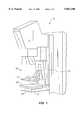
- FIG. 1is a perspective view of mammography apparatus constructed in accordance with the principles of the present invention
- FIG. 2is a partial elevation side view of the compression assembly of the mammography apparatus of FIG. 1;
- FIG. 3is a partial elevation side view of a sonography system constructed in accordance with the principles of the present invention.
- FIGS. 4A and 4Bare, respectively, elevation side views of tissue disposed within the compression assembly of FIG. 3, before and after the upper compression plate is lowered to compress the tissue.
- the present inventionis directed to a compression assembly for use in radiographic, sonographic, or similar type imaging systems, which enhances imaging of biological tissue in the vicinity of the patient's body wall.
- the present inventionwhen applied to breast imaging technology, the present invention induces traction in breast tissue as the tissue is compressed, thereby drawing a portion of the internal tissue structure adjacent to the patient's chest wall within the imaging field. While illustrative embodiments are described hereinbelow for use in conducting X-ray and ultrasound imaging of breast tissue, other applications of the present invention to imaging of biological tissue will be apparent to one of skill in the art.
- Mammography apparatus 10including a compression assembly 20 constructed in accordance principles of the present invention is described.
- Mammography apparatus 10comprises X-ray generating device 11, compression assembly 20 and diffraction grating and film cassette holder 12.
- Compression assembly 20includes upper compression plate 21, lower compression surface 22 having proximal edge 23 and support assembly 30 that enables upper compression plate 21 to be displaced rearwardly from proximal edge 23 when upper compression plate is lowered towards lower compression surface 22.
- FIG. 2an illustrative arrangement of support assembly 30 of FIG. 1 is shown in which the exterior housing of support assembly 30 has been removed to reveal a screw-type drive arrangement for upper compression plate 21.
- Other drive meansboth motor-driven and manual, will occur to those of skill in the art, and the drive arrangement provided in FIG. 2 is intended to be illustrative only.
- Screw block 32includes threaded bores 33 through which two threaded bars 34 pass (only one of which is visible in FIG. 2). Threaded bars 34, which provide vertical positioning means for screw block 32, are journaled between support block 35 and thrust bearing 36.
- Motor 37is mounted to support block 35 via plate 38 and coupled to threaded bars 34, so that rotation of motor 37 rotates threaded bars in threaded bores 33 of screw block 32, thereby raising or lowering support arm 31 and upper compression plate 21.
- vertical positioning meansare canted forward from the vertical by angle ⁇ of up to about 15 degrees, and preferably about 4 degrees.
- Lower surface 24 of upper compression plate 21is also raised by angle ⁇ , from the horizontal, of up to about 45 degrees, and preferably about 4 degrees.
- angle ⁇ of the vertical positioning means and angle ⁇ of lower surface 24 of upper compression plate 21result in two effects that cause the internal structures near the patient's chest wall to be drawn into the imaging field.
- proximal-most edge 24 of the upper compression plateis displaced slightly rearwardly relative to proximal edge 23 of lower compression surface 22.
- Rearward displacement of upper compression plate 24 with respect to lower compression surface 22induces a state of traction in tissue disposed between the compression plates, and especially in the tissue contacting lower surface 25 of upper compression plate 21.
- the tissue in the vicinity of the patient's chest wallis drawn between upper compression plate 21 and lower compression surface 22.
- tissueis drawn into the imaging field as the tissue is flattened to a substantially uniform or tapered thickness.
- the tendency in previously known compression assemblies for the compressive force to urge tissue inward through the patient's chest wallis reduced.
- the compression arrangement of the present inventiondoes not introduce local discontinuities in the thickness of the tissue adjacent the patient's chest wall, unlike the aforementioned Kopans patent, it is expected that a single exposure will provide adequate clarity for tissue near the patient's chest wall as well as for tissue within the central portions of the imaging field.
- one or both of lower surface 25 of upper compression plate 21 and lower compression surface 22may include a slightly roughened or tacky surface, for example, a sheet or strip of rubber, so that the tissue adheres or is gripped by the respective surface at points of contact.
- a gel padmay be used to provide this functionality.
- ultrasound scanner 50comprises housing 51 enclosing a gantry carried ultrasound transducer 53 (see FIGS. 4) or an array of piezoelectric ultrasound transducer elements as described, for example, with respect to FIGS. 3 and 7 of the aforementioned U.S. Pat. No. 5,474,072, the entirety of which is incorporated herein by reference.
- the ultrasound scannermay be manually driven, as described in concurrently filed, copending, and commonly assigned U.S. patent application Ser. No. 08/680,595.
- the upper surface of housing 51forms a lower compression surface 52 against which the tissue is immobilized.
- the compression surface 52is preferably formed of a sonolucent material.
- a gel padnot shown, preferably is disposed between the tissue and compression surface 52 to provide acoustic coupling therebetween.
- compression assembly 40comprises compression surface 52 of ultrasound scanner 50, upper compression plate 41, vertical positioning bars 42 (only one of which is visible in FIG. 3), slide block 43 and top block 44.
- Slide block 43is engaged with gearing 45 disposed along the rearward faces of vertical positioning bars 42 to provide a rack and pinion-type drive.
- a suitable motor and gearing or manual drive(neither shown) is connected to slide block 43 for driving slide block in directions substantially perpendicular to the horizontal, i.e., towards and away from compression surface 52.
- vertical positioning bars 42are canted forward from the vertical by angle ⁇ of up to about 15 degrees, and preferably about 4 degrees.
- Lower surface 46 of upper compression plate 41is also raised angle ⁇ , from the horizontal, of up to about 45 degrees, and preferably about 4 degrees.
- compression surface 52 of housing 51 of ultrasound scanner 50is also inclined inward towards the patient's chest wall, relative to the horizontal, by angle ⁇ , for reasons described in greater detail hereinbelow.
- Angle ⁇may be up to 90 degrees from the horizontal, and is preferably about 4 degrees.
- FIGS. 4A and 4Boperation of the traction-inducing effect of compression assembly 40 is illustrated.
- the combination of angle ⁇ of vertical positioning bars 43 and angle ⁇ of lower surface 46 of upper compression plate 41cause internal structure 101 of breast tissue 100 near the patient's chest wall 102 to be drawn into the imaging field.
- the upper compression plate 41is lowered towards compression surface 52, the upper compression plate is displaced slightly rearwardly relative to compression surface 52, thereby inducing a state of traction in tissue 100 and internal structure 101 disposed therebetween.
- tissue 100 and internal structure 101are drawn into the imaging field as they are flattened to a substantially uniform or gradually tapered thickness.
- the tendency in previously known compression assemblies for the compressive force to urge tissue out from between the compression surfaces, and thus out of the imaging field,is reduced.
- ultrasound transducer 53 enclosed within ultrasound scanner housing 51preferably is acoustically coupled to the underside of compression surface 52 via a suitable lubricious couplant, for example, glycerol.
- a suitable lubricious couplantfor example, glycerol.
- the traction-inducing compression assembly 40 of the present inventionis expected to provide enhanced imaging within the field of the compression area superior to that which may be achievable using the system described in the aforementioned Kopans patent, because there are no local discontinuities in the tissue thickness which may effect exposure of the image.
- the compression arrangement of the present inventionobviates the need for a ridge near the patient's chest wall, thereby eliminating material near the patient's chest wall that might interfere with imaging internal tissue structure extending partially within the patient's chest wall.
Landscapes
- Health & Medical Sciences (AREA)
- Life Sciences & Earth Sciences (AREA)
- Engineering & Computer Science (AREA)
- Medical Informatics (AREA)
- Surgery (AREA)
- Animal Behavior & Ethology (AREA)
- Radiology & Medical Imaging (AREA)
- Nuclear Medicine, Radiotherapy & Molecular Imaging (AREA)
- Biomedical Technology (AREA)
- Heart & Thoracic Surgery (AREA)
- Biophysics (AREA)
- Molecular Biology (AREA)
- Physics & Mathematics (AREA)
- Pathology (AREA)
- General Health & Medical Sciences (AREA)
- Public Health (AREA)
- Veterinary Medicine (AREA)
- High Energy & Nuclear Physics (AREA)
- Optics & Photonics (AREA)
- Dentistry (AREA)
- Oral & Maxillofacial Surgery (AREA)
- Apparatus For Radiation Diagnosis (AREA)
- Ultra Sonic Daignosis Equipment (AREA)
- Magnetic Resonance Imaging Apparatus (AREA)
Abstract
Description
This invention relates to apparatus and methods for conducting an examination of biological tissue, especially breast tissue, that provides enhanced imaging of the tissue. In particular, the present invention provides an assembly for inducing traction in breast tissue while the tissue is being compressed, thereby drawing the tissue away from the chest wall.
Apparatus and methods are known for imaging the internal structure of body tissue, for example, using radiographic and sonographic techniques, to identify tumorous masses and other abnormalities. Such imaging capability has provided significant benefits in the early diagnosis of breast cancer.
In radiographic systems, breast tissue typically is compressed between a compression plate and a diffraction grid to form a substantially uniform thickness. The compressive forces applied by the system assist in spreading the internal structures of the tissue, immobilize the tissue against movement during exposure of the X-ray film or imaging elements, and permit the use of lower dosages of X-rays to obtain an image.
In addition, flattening the tissue to a uniform thickness enables most of the area of the breast to be imaged with a single exposure, so that only the reduced-thickness portions at the periphery of the breast are overexposed. Typically, the periphery of the breast is imaged using a second, lower dose of radiation than is used for the uniform thickness of the breast.
In sonographic systems, such as Brenden U.S. Pat. No. 3,765,403, where the imaging is conducted using ultrasound technology, the breast tissue typically is suspended in a water bath. In such systems the tissue is not compressed, but is merely urged into the water bath by gravity and the patient's weight. Alternatively, in the system described in commonly assigned U.S. Pat. No. 5,474,072, the breast is compressed between first and second compression surfaces, so that the breast is flattened to a uniform thickness for both radiographic and ultrasound imaging.
A drawback common to both previously known radiographic and sonographic imaging systems is the inability to image tissue in the vicinity of the chest wall. In the case of radiographic systems and the sonographic system described in the above-mentioned U.S. Pat. No. 5,474,072, compressive forces applied to the breast tissue to flatten it to a uniform thickness tend to force tissue out from between the compression surfaces. Consequently, internal breast structures near the patient's chest wall are forced inward through the patient's chest wall, and therefore are difficult to bring within the field of the radiographic or sonographic imaging device. Alternatively, in water bath sonographic systems, only gravity, and perhaps the patient's body weight, are available to urge the internal tissue structures within the field of the ultrasound scanner.
An attempt to overcome the above disadvantages of previously known compression arrangements is provided in Kopans U.S. Pat. No. 4,962,515. That patent describes a compression assembly comprising upper and lower compression plates, each of the upper and lower compression plates including a ridge disposed adjacent the patient's chest wall. The ridge serves to grip the patient's tissue near the chest wall and counteract the tendency of compressive forces to push the tissue inward through the patient's chest wall. Such a system has two perceived drawbacks, however. First, the tissue in the vicinity of the ridges is expected to have a localized reduction in thickness in the region adjacent the breast wall which is expected to become overexposed, in a manner similar to that of the breast periphery. Second, the additional thickness of the compression surfaces caused by the present of the ridges near the chest wall is expected to interfere with the ability to image tissue between or proximally (with respect to the patient's chest) of the ridge location.
Another arrangement for enhancing imaging of breast tissue is described in Niklason et al. U.S. Pat. No. 5,506,877. In the arrangement described in that patent a movable upper breast paddle is described which attempts to mimic the contours of the breast. The paddle is arranged so as to pivot along a line adjacent to the patient's chest wall. A drawback of this system is that it does not improve imaging near the patient's chest wall. Rather, the location of the pivot point near the chest wall is expected only to exacerbate the difficulty in providing accurate imaging near the chest wall, since the paddle is expected to exert a lateral compressive load on the tissue forcing it inward through the patient's chest wall.
In view of the foregoing, it would be desirable to provide a compression assembly for enhancing imaging of internal tissue structures in the vicinity of a patient's chest wall.
It would further be desirable to provide a compression assembly for use in radiographic or sonographic imaging systems that provides enhanced imaging in the vicinity of a patient's chest wall without reducing the thickness of the compressed tissue substantially from that of adjacent tissue regions, thus reducing overexposure of the tissue near the chest wall.
It would also be desirable to provide a compression assembly for use in radiographic and sonographic systems that does not interfere with the capability of the system to provide partial imaging within the patient's chest wall.
In view of the foregoing, it is an object of this invention to provide a compression assembly for enhancing imaging of internal tissue structures in the vicinity of a patient's chest wall.
It is another object of the present invention to provide a compression assembly for use in radiographic or sonographic imaging systems that provides enhanced imaging in the vicinity of a patient's chest wall without reducing the thickness of the compressed tissue substantially from that of adjacent tissue regions, thus reducing overexposure of the tissue near the chest wall.
It is yet another object of this invention to provide a compression assembly for use in radiographic and sonographic systems that does not interfere with the capability of the system to provide at least partial imaging within the patient's chest wall.
These and other objects of the invention are accomplished in accordance with the principles of the invention by providing a compression assembly that induces a state of traction in a biological tissue, especially breast tissue, while the tissue is being compressed to a substantially uniform or tapered thickness. In a preferred embodiment, the compression assembly includes upper and lower compression surfaces that are displaced laterally when moved perpendicularly with respect to one another. In particular, an upper compression surface is arranged to be displaced laterally in a distal direction when moved towards the lower compression surface, thereby drawing the tissue in contact with the upper compression surface away from the patient's chest wall as the tissue is being flattened between the compression surfaces. To assist this traction effect, one or both of the compression surfaces may have slightly roughened or tacky surface to grip the tissue in contact therewith.
In an alternative embodiment for use with an ultrasound scanner, as described for example, in the above-mentioned U.S. Pat. No. 5,474,072, the lower compression plate is angled relative to a plane parallel with the patient's chest wall, so that the ultrasound signals can penetrate the patient's chest wall to provide partial imaging of internal tissue structures that extend within the patient's chest line.
Further features of the invention, its nature and various advantages will be more apparent from the accompanying drawings and the following detailed description of the preferred embodiments, in which:
FIG. 1 is a perspective view of mammography apparatus constructed in accordance with the principles of the present invention;
FIG. 2 is a partial elevation side view of the compression assembly of the mammography apparatus of FIG. 1;
FIG. 3 is a partial elevation side view of a sonography system constructed in accordance with the principles of the present invention; and
FIGS. 4A and 4B are, respectively, elevation side views of tissue disposed within the compression assembly of FIG. 3, before and after the upper compression plate is lowered to compress the tissue.
In overview, the present invention is directed to a compression assembly for use in radiographic, sonographic, or similar type imaging systems, which enhances imaging of biological tissue in the vicinity of the patient's body wall. In particular, when applied to breast imaging technology, the present invention induces traction in breast tissue as the tissue is compressed, thereby drawing a portion of the internal tissue structure adjacent to the patient's chest wall within the imaging field. While illustrative embodiments are described hereinbelow for use in conducting X-ray and ultrasound imaging of breast tissue, other applications of the present invention to imaging of biological tissue will be apparent to one of skill in the art.
Referring to FIG. 1, an illustrative embodiment ofmammography apparatus 10 including acompression assembly 20 constructed in accordance principles of the present invention is described.Mammography apparatus 10 comprisesX-ray generating device 11,compression assembly 20 and diffraction grating andfilm cassette holder 12.Compression assembly 20 includesupper compression plate 21,lower compression surface 22 havingproximal edge 23 and support assembly 30 that enablesupper compression plate 21 to be displaced rearwardly fromproximal edge 23 when upper compression plate is lowered towardslower compression surface 22.
Referring now to FIG. 2, an illustrative arrangement of support assembly 30 of FIG. 1 is shown in which the exterior housing of support assembly 30 has been removed to reveal a screw-type drive arrangement forupper compression plate 21. Other drive means, both motor-driven and manual, will occur to those of skill in the art, and the drive arrangement provided in FIG. 2 is intended to be illustrative only.
In accordance with the present invention, vertical positioning means (threaded bars 34) are canted forward from the vertical by angle θ of up to about 15 degrees, and preferably about 4 degrees.Lower surface 24 ofupper compression plate 21 is also raised by angle Φ, from the horizontal, of up to about 45 degrees, and preferably about 4 degrees.
The combination of angle θ of the vertical positioning means and angle Φ oflower surface 24 ofupper compression plate 21 result in two effects that cause the internal structures near the patient's chest wall to be drawn into the imaging field. In particular, whenupper compression plate 21 is lowered towardslower compression surface 22,proximal-most edge 24 of the upper compression plate is displaced slightly rearwardly relative toproximal edge 23 oflower compression surface 22. Rearward displacement ofupper compression plate 24 with respect tolower compression surface 22, induces a state of traction in tissue disposed between the compression plates, and especially in the tissue contactinglower surface 25 ofupper compression plate 21. Thus, ascompression plate 21 is lowered towardlower compression surface 22, the tissue in the vicinity of the patient's chest wall is drawn betweenupper compression plate 21 andlower compression surface 22.
As a result of angling the upper compression plate and canting the vertical positioning means, tissue is drawn into the imaging field as the tissue is flattened to a substantially uniform or tapered thickness. Thus, the tendency in previously known compression assemblies for the compressive force to urge tissue inward through the patient's chest wall is reduced. Moreover, because the compression arrangement of the present invention does not introduce local discontinuities in the thickness of the tissue adjacent the patient's chest wall, unlike the aforementioned Kopans patent, it is expected that a single exposure will provide adequate clarity for tissue near the patient's chest wall as well as for tissue within the central portions of the imaging field.
In addition, to further enhance the above-described traction effect, one or both oflower surface 25 ofupper compression plate 21 andlower compression surface 22 may include a slightly roughened or tacky surface, for example, a sheet or strip of rubber, so that the tissue adheres or is gripped by the respective surface at points of contact. For sonographic applications, such as described below, a gel pad may be used to provide this functionality.
With respect to FIG. 3,compression assembly 40 as described hereinabove is shown as modified for use withultrasound scanner 50 for use in a sonography system.Ultrasound scanner 50 compriseshousing 51 enclosing a gantry carried ultrasound transducer 53 (see FIGS. 4) or an array of piezoelectric ultrasound transducer elements as described, for example, with respect to FIGS. 3 and 7 of the aforementioned U.S. Pat. No. 5,474,072, the entirety of which is incorporated herein by reference. Alternatively, the ultrasound scanner may be manually driven, as described in concurrently filed, copending, and commonly assigned U.S. patent application Ser. No. 08/680,595. The upper surface ofhousing 51 forms alower compression surface 52 against which the tissue is immobilized. As described in the above-incorporated patent, thecompression surface 52 is preferably formed of a sonolucent material. A gel pad, not shown, preferably is disposed between the tissue andcompression surface 52 to provide acoustic coupling therebetween.
In the illustrative embodiment of FIG. 3,compression assembly 40 comprisescompression surface 52 ofultrasound scanner 50,upper compression plate 41, vertical positioning bars 42 (only one of which is visible in FIG. 3),slide block 43 andtop block 44.Slide block 43 is engaged withgearing 45 disposed along the rearward faces of vertical positioning bars 42 to provide a rack and pinion-type drive. A suitable motor and gearing or manual drive (neither shown) is connected to slideblock 43 for driving slide block in directions substantially perpendicular to the horizontal, i.e., towards and away fromcompression surface 52.
In accordance with the present invention, vertical positioning bars 42 are canted forward from the vertical by angle θ of up to about 15 degrees, and preferably about 4 degrees.Lower surface 46 ofupper compression plate 41 is also raised angle Φ, from the horizontal, of up to about 45 degrees, and preferably about 4 degrees. In addition,compression surface 52 ofhousing 51 ofultrasound scanner 50 is also inclined inward towards the patient's chest wall, relative to the horizontal, by angle Ω, for reasons described in greater detail hereinbelow. Angle Ω may be up to 90 degrees from the horizontal, and is preferably about 4 degrees. In one intended use of the ultrasonic scanner of the present invention, wherein the angle Ω is 90 degrees,upper compression plate 41 and vertical positioning bars 42 are removed so thatcompression surface 52 may be pressed directly against the patient's chest wall, for example, for imaging features within the chest wall.
Referring now to FIGS. 4A and 4B, operation of the traction-inducing effect ofcompression assembly 40 is illustrated. As for the embodiment of FIG. 2, the combination of angle θ of vertical positioning bars 43 and angle Φ oflower surface 46 ofupper compression plate 41 causeinternal structure 101 ofbreast tissue 100 near the patient'schest wall 102 to be drawn into the imaging field. Whenupper compression plate 41 is lowered towardscompression surface 52, the upper compression plate is displaced slightly rearwardly relative tocompression surface 52, thereby inducing a state of traction intissue 100 andinternal structure 101 disposed therebetween.
Consequently, by angling the upper compression plate and canting the vertical positioning bars,tissue 100 andinternal structure 101 are drawn into the imaging field as they are flattened to a substantially uniform or gradually tapered thickness. The tendency in previously known compression assemblies for the compressive force to urge tissue out from between the compression surfaces, and thus out of the imaging field, is reduced.
Still referring to FIGS. 4, the advantage of loweringcompression surface 52 ofultrasound scanner 50 horizontal by angle Ω relative to the horizontal is now described. As depicted in FIGS. 4,ultrasound transducer 53 enclosed withinultrasound scanner housing 51 preferably is acoustically coupled to the underside ofcompression surface 52 via a suitable lubricious couplant, for example, glycerol. By loweringcompression surface 52 from the horizontal by an angle Ω, acoustic signals emanating fromultrasound transducer 53 are no longer perpendicular to the patient'schest wall 102, but will penetrate the chest wall to an extent beyond the proximal edge ofupper compression plate 41, as indicated byarrows 54 in FIG. 4B. Thus, not only will the traction-inducing effect ofcompression assembly 40 draw tissue into the imaging field, but in addition, by angling the compression surface of the ultrasound scanner, an ultrasound image of internal structures extending partially within the patient'schest wall 102 may be imaged.
As will be appreciated by those of skill in the art, the traction-inducingcompression assembly 40 of the present invention is expected to provide enhanced imaging within the field of the compression area superior to that which may be achievable using the system described in the aforementioned Kopans patent, because there are no local discontinuities in the tissue thickness which may effect exposure of the image. Further, when employed in a sonographic system, the compression arrangement of the present invention obviates the need for a ridge near the patient's chest wall, thereby eliminating material near the patient's chest wall that might interfere with imaging internal tissue structure extending partially within the patient's chest wall.
It will be understood that the foregoing is merely illustrative of the apparatus and methods of the present invention, and that various modifications can be made by those skilled in the art without departing from the scope and spirit of the invention.
Claims (20)
1. A compression assembly for imaging biological tissue, the compression assembly for use with imaging apparatus that provides a visualization of an internal structure of the biological tissue, the compression assembly comprising:
a fixed compression surface having a fixed first proximal edge;
a second compression surface having a second proximal edge;
means for positioning the first compression surface substantially opposite and spaced apart from the second compression surface to define an imaging field, the means for positioning including means for moving the first compression surface relative to the second compression surface so that the first proximal edge moves rearwardly of the second proximal edge when the first compression surface is moved towards the second compression surface,
thereby inducing traction in a biological tissue when partially inserted between the first compression surface and the second compression surface, the traction assisting in drawing the internal structure of the biological tissue within the imaging field.
2. The compression assembly as defined in claim 1 wherein the means for positioning comprises a support member connected to the first compression surface and a vertical positioning means, the vertical positioning means angled forward from a plane parallel to a patient's chest wall by an angle θ.
3. The compression assembly as defined in claim 2 wherein the vertical positioning means comprises a screw-type drive.
4. The compression assembly as defined in claim 2 wherein the vertical positioning means comprises a rack and pinion-type drive.
5. The compression assembly as defined in claim 2 wherein the angle θ is less than about fifteen degrees.
6. The compression assembly as defined in claim 1 wherein the first compression surface is inclined inward towards a patient's chest wall by an angle Φ, relative to a plane orthogonal to the patient's chest wall.
7. The compression assembly as defined in claim 6 wherein the angle Φ is less than about forty-five degrees.
8. The compression assembly as defined in claim 1 wherein the second compression surface is inclined inward towards a patient's chest wall by an angle Ω, relative to a plane orthogonal to the patient's chest wall.
9. The compression assembly as defined in claim 8 wherein the angle Ω is less than ninety degrees.
10. The compression assembly as defined in claim 1 wherein at least one of the first and second compression surfaces grips tissue when tissue is disposed in contact therewith.
11. Apparatus for imaging biological tissue comprising an imaging system that provides a visualization of an internal structure of the biological tissue and a compression assembly comprising a first compression surface having a fixed first proximal edge, a second compression surface having a second proximal edge, and means for positioning the first compression surface substantially opposite and spaced apart from the second compression surface to define an imaging field, the improvement comprising:
means for moving included within the means for positioning for moving the first compression surface relative to the second compression surface so that the first proximal edge moves rearwardly of the second proximal edge as the first compression surface is moved towards the second compression surface.
12. The apparatus as defined in claim 11 wherein the means for positioning comprises a support member connected to the first compression surface and a vertical positioning means, the vertical positioning means angled forward from a plane parallel to a patient's chest wall by an angle θ.
13. The apparatus as defined in claim 11 wherein the first compression surface is inclined inward towards a patient's chest wall by an angle Φ, relative to a plane orthogonal to the patient's chest wall.
14. The apparatus as defined in claim 11 wherein the second compression surface is inclined inward toward a patient's chest wall by an angle Ω, relative to a plane orthogonal to the patient's chest wall.
15. The compression assembly as defined in claim 11 wherein at least one of the first and second compression surfaces grips tissue when tissue is disposed in contact therewith.
16. The apparatus as defined in claim 11 wherein the imaging system generates radiographic images.
17. The apparatus as defined in claim 11 wherein the imaging system generates ultrasound images.
18. A method of compressing biological tissue to a substantially uniform thickness for use with an imaging apparatus that provides a visualization of an internal structure of the biological tissue, the method comprising steps of
providing a first compression surface having a fixed proximal edge;
providing a second compression surface having a proximal edge;
inserting a biological tissue between the first and second compression surfaces and in contact therewith;
translating the first compression surface so that the first proximal edge moves distally of the second proximal edge as the first compression surface is moved towards the second compression surface, thereby inducing a state of traction in the biological tissue as the biological tissue is compressed between the first compression surface and the second compression surface.
19. The method as defined in claim 18 further comprising steps of tilting the first compression surface slightly upward by an angle Φ with respect to a horizontal plane, and maintaining the first compression surface at the angle Φ during the step of translating.
20. The method as defined in claim 18 further comprising steps of tilting the second compression surface slightly downward by an angle Ω with respect to a horizontal plane, and maintaining the second compression surface at the angle Ω during the step of translating.
Priority Applications (6)
| Application Number | Priority Date | Filing Date | Title |
|---|---|---|---|
| US08/680,560US5851180A (en) | 1996-07-12 | 1996-07-12 | Traction-inducing compression assembly for enhanced tissue imaging |
| DE69716951TDE69716951T2 (en) | 1996-07-12 | 1997-07-08 | COMPRESSION DEVICE FOR IMAGING TISSUE UNDER TRACTION |
| EP97933229AEP0955886B1 (en) | 1996-07-12 | 1997-07-08 | Traction-inducing compression assembly for enhanced tissue imaging |
| PCT/US1997/011434WO1998002094A1 (en) | 1996-07-12 | 1997-07-08 | Traction-inducing compression assembly for enhanced tissue imaging |
| AU36465/97AAU717295B2 (en) | 1996-07-12 | 1997-07-08 | Traction-inducing compression assembly for enhanced tissue imaging |
| ES97933229TES2185959T3 (en) | 1996-07-12 | 1997-07-08 | TRACTION INDUCTOR COMPRESSION ASSEMBLY FOR IMPROVED TISSULAR IMAGE GENERATION. |
Applications Claiming Priority (1)
| Application Number | Priority Date | Filing Date | Title |
|---|---|---|---|
| US08/680,560US5851180A (en) | 1996-07-12 | 1996-07-12 | Traction-inducing compression assembly for enhanced tissue imaging |
Publications (1)
| Publication Number | Publication Date |
|---|---|
| US5851180Atrue US5851180A (en) | 1998-12-22 |
Family
ID=24731598
Family Applications (1)
| Application Number | Title | Priority Date | Filing Date |
|---|---|---|---|
| US08/680,560Expired - LifetimeUS5851180A (en) | 1996-07-12 | 1996-07-12 | Traction-inducing compression assembly for enhanced tissue imaging |
Country Status (6)
| Country | Link |
|---|---|
| US (1) | US5851180A (en) |
| EP (1) | EP0955886B1 (en) |
| AU (1) | AU717295B2 (en) |
| DE (1) | DE69716951T2 (en) |
| ES (1) | ES2185959T3 (en) |
| WO (1) | WO1998002094A1 (en) |
Cited By (49)
| Publication number | Priority date | Publication date | Assignee | Title |
|---|---|---|---|---|
| WO2000032109A1 (en)* | 1998-11-27 | 2000-06-08 | Planmed Oy | Method and apparatus for tissue imaging |
| US20030007598A1 (en)* | 2000-11-24 | 2003-01-09 | U-Systems, Inc. | Breast cancer screening with adjunctive ultrasound mammography |
| US20030167004A1 (en)* | 1998-11-25 | 2003-09-04 | Dines Kris A. | Mammography method and apparatus |
| US20030194115A1 (en)* | 2002-04-15 | 2003-10-16 | General Electric Company | Method and apparatus for providing mammographic image metrics to a clinician |
| US20030194050A1 (en)* | 2002-04-15 | 2003-10-16 | General Electric Company | Multi modality X-ray and nuclear medicine mammography imaging system and method |
| US20030194048A1 (en)* | 2002-04-15 | 2003-10-16 | General Electric Company | Reprojection and backprojection methods and algorithms for implementation thereof |
| US20030194121A1 (en)* | 2002-04-15 | 2003-10-16 | General Electric Company | Computer aided detection (CAD) for 3D digital mammography |
| US20030194051A1 (en)* | 2002-04-15 | 2003-10-16 | General Electric | Tomosynthesis X-ray mammogram system and method with automatic drive system |
| US20030215057A1 (en)* | 2002-05-15 | 2003-11-20 | General Electric Company | Scatter correction method for non-stationary X-ray acquisitions |
| FR2842722A1 (en)* | 2002-07-29 | 2004-01-30 | Ge Med Sys Global Tech Co Llc | Mammography instrument has an endless shaft and drive motor with a gear mechanism that enables simple manual compression of the breast within its support cup and against the breast support plate |
| US6707878B2 (en) | 2002-04-15 | 2004-03-16 | General Electric Company | Generalized filtered back-projection reconstruction in digital tomosynthesis |
| US20040068170A1 (en)* | 2000-11-24 | 2004-04-08 | U-Systems Inc.(Vii) | Breast cancer screening with ultrasound image overlays |
| US20040181152A1 (en)* | 2003-03-11 | 2004-09-16 | Zhang Heidi D. | Ultrasound breast screening device |
| US6805669B2 (en) | 2001-01-25 | 2004-10-19 | Rebecca L. Swanbom | Method and device for marking skin during an ultrasound examination |
| US6846289B2 (en) | 2003-06-06 | 2005-01-25 | Fischer Imaging Corporation | Integrated x-ray and ultrasound medical imaging system |
| US20050089205A1 (en)* | 2003-10-23 | 2005-04-28 | Ajay Kapur | Systems and methods for viewing an abnormality in different kinds of images |
| US20050113684A1 (en)* | 2003-11-25 | 2005-05-26 | General Electric Company | Compliant probe interface assembly |
| US6974255B1 (en)* | 2002-08-28 | 2005-12-13 | American Mammographics, Inc. | Mammographic paddle |
| US7223238B2 (en) | 2001-01-25 | 2007-05-29 | Swanbom Rebecca L | Method and device for marking skin during an ultrasound examination |
| US20070225605A1 (en)* | 2001-01-25 | 2007-09-27 | Swanbom Rebecca L | Method and Device for Marking Skin During an Ultrasound Examination |
| US7313259B2 (en) | 2003-11-26 | 2007-12-25 | General Electric Company | Method, system and computer program product for multi-modality registration using virtual cursors |
| WO2008020439A2 (en) | 2006-08-17 | 2008-02-21 | Sialo Technology Israel Ltd | All-in-one optical microscopic handle |
| US20080154090A1 (en)* | 2005-01-04 | 2008-06-26 | Dune Medical Devices Ltd. | Endoscopic System for In-Vivo Procedures |
| US20080269613A1 (en)* | 2004-04-26 | 2008-10-30 | Summers Douglas G | Versatile Breast Ultrasound Scanning |
| US20080287750A1 (en)* | 2002-01-04 | 2008-11-20 | Dune Medical Devices Ltd. | Ergonomic probes |
| JP2009508539A (en)* | 2005-08-04 | 2009-03-05 | デューン メディカル デヴァイシズ リミテッド | Tissue characterization probe with effective sensor-to-tissue contact |
| USD597210S1 (en)* | 2008-05-19 | 2009-07-28 | Fujifilm Corporation | Mammography equipment |
| US7597663B2 (en) | 2000-11-24 | 2009-10-06 | U-Systems, Inc. | Adjunctive ultrasound processing and display for breast cancer screening |
| US7615008B2 (en) | 2000-11-24 | 2009-11-10 | U-Systems, Inc. | Processing and displaying breast ultrasound information |
| US7630532B1 (en)* | 2002-01-18 | 2009-12-08 | Hologic, Inc. | Method and apparatus for correction of mammograms for non-uniform breast thickness |
| US7940966B2 (en) | 2000-11-24 | 2011-05-10 | U-Systems, Inc. | Full-field breast image data processing and archiving |
| JP2011212111A (en)* | 2010-03-31 | 2011-10-27 | Fujifilm Corp | Compression paddle and x-ray imaging apparatus |
| US20120143083A1 (en)* | 2010-12-01 | 2012-06-07 | Andrew Kwai | Devices and methods for improving the usability of stereotactic imaging for performing a breast biopsy |
| US20120238859A1 (en)* | 2010-02-02 | 2012-09-20 | Canon Kabushiki Kaisha | Measuring apparatus |
| US8721565B2 (en) | 2005-08-04 | 2014-05-13 | Dune Medical Devices Ltd. | Device for forming an effective sensor-to-tissue contact |
| NL2009856C2 (en)* | 2012-11-21 | 2014-05-27 | Amc Amsterdam | Mammography apparatus. |
| US20150190101A1 (en)* | 2001-10-19 | 2015-07-09 | Hologic, Inc. | Mammography system and method employing offset compression paddles, automatic collimation, and retractable anti-scatter grid |
| US9867668B2 (en) | 2008-10-20 | 2018-01-16 | The Johns Hopkins University | Environment property estimation and graphical display |
| US9883846B2 (en)* | 2013-03-29 | 2018-02-06 | General Electric Company | Mammography device |
| US9950194B2 (en) | 2014-09-09 | 2018-04-24 | Mevion Medical Systems, Inc. | Patient positioning system |
| US10463319B2 (en)* | 2016-10-20 | 2019-11-05 | Canon Medical Systems Corporation | Compression plate, X-ray diagnostic apparatus and method of manufacturing the compression plate |
| US10729403B2 (en)* | 2010-12-14 | 2020-08-04 | Hologic, Inc. | System and method for fusing three dimensional image data from a plurality of different imaging systems for use in diagnostic imaging |
| US10827997B2 (en)* | 2018-04-27 | 2020-11-10 | Fujifilm Corporation | Mammography apparatus |
| US10956701B2 (en) | 2016-05-27 | 2021-03-23 | Hologic, Inc. | Synchronized surface and internal tumor detection |
| US20220096024A1 (en)* | 2020-09-30 | 2022-03-31 | Fujifilm Corporation | Compression member, support member, and mammography apparatus |
| US11317878B2 (en) | 2001-10-19 | 2022-05-03 | Hologic, Inc. | Mammography system and method employing offset compression paddles, automatic collimation, and retractable anti-scatter grid |
| WO2023190788A1 (en)* | 2022-03-29 | 2023-10-05 | 富士フイルム株式会社 | Compression member, image acquisition device, and image acquisition method |
| US11903635B2 (en) | 2020-02-28 | 2024-02-20 | Covidien Lp | Electrosurgical forceps including tissue indication |
| US12226233B2 (en) | 2019-07-29 | 2025-02-18 | Hologic, Inc. | Personalized breast imaging system |
Families Citing this family (10)
| Publication number | Priority date | Publication date | Assignee | Title |
|---|---|---|---|---|
| US6589352B1 (en)* | 1999-12-10 | 2003-07-08 | Applied Materials, Inc. | Self aligning non contact shadow ring process kit |
| JP4295283B2 (en)* | 2003-01-17 | 2009-07-15 | ヒー−ブーン パク | Ultrasonic inspection system for deformable objects |
| US11259759B2 (en) | 2011-11-18 | 2022-03-01 | Hologic Inc. | X-ray mammography and/or breast tomosynthesis using a compression paddle |
| US9855014B2 (en) | 2014-12-16 | 2018-01-02 | General Electric Company | Compression paddle for use in breast imaging |
| US9949719B2 (en)* | 2014-12-16 | 2018-04-24 | General Electric Company | Breast imaging method and system |
| CN117838159A (en) | 2016-11-08 | 2024-04-09 | 豪洛捷公司 | Imaging using curved compression elements |
| WO2019033022A1 (en)* | 2017-08-11 | 2019-02-14 | Hologic, Inc. | Breast compression paddle having an inflatable jacket |
| US11672493B2 (en) | 2017-08-11 | 2023-06-13 | Hologic, Inc. | Breast compression paddle with access corners |
| EP4129188A1 (en) | 2017-08-16 | 2023-02-08 | Hologic, Inc. | Techniques for breast imaging patient motion artifact compensation |
| JP7742349B2 (en) | 2020-01-24 | 2025-09-19 | ホロジック, インコーポレイテッド | Horizontally displaceable foam breast compression paddles |
Citations (103)
| Publication number | Priority date | Publication date | Assignee | Title |
|---|---|---|---|---|
| US3765403A (en)* | 1968-05-20 | 1973-10-16 | Holotron Corp | Ultrasonic imaging techniques and mammograph equipment |
| DE2535576A1 (en)* | 1974-08-09 | 1976-02-26 | Bush Boake Allen Ltd | PERFUME PRODUCTS, THE PROCESS FOR THEIR MANUFACTURING AND THEIR USE |
| US3971950A (en)* | 1975-04-14 | 1976-07-27 | Xerox Corporation | Independent compression and positioning device for use in mammography |
| US3991316A (en)* | 1972-03-24 | 1976-11-09 | Siemens Aktiengesellschaft | Apparatus for X-ray examination |
| SU896539A2 (en) | 1980-04-14 | 1982-01-07 | Каунасский Политехнический Институт Им.Антанаса Снечкуса | Ultrasonic transducer for biological investigations |
| GB2094590A (en) | 1981-02-12 | 1982-09-15 | Univ New York | Apparatus for stereotactic surgery |
| DE3226976A1 (en) | 1981-07-20 | 1983-02-03 | Siemens AG, 1000 Berlin und 8000 München | ULTRASONIC APPARATUS FOR MEDICAL EXAMINATIONS |
| DE3222053A1 (en) | 1982-06-11 | 1983-12-15 | Siemens AG, 1000 Berlin und 8000 München | Apparatus for the ultrasonic examination of the female breast |
| DE3227624A1 (en) | 1982-07-23 | 1984-01-26 | Siemens AG, 1000 Berlin und 8000 München | Device for examining the female breast using ultrasound |
| EP0105812A1 (en)* | 1982-10-05 | 1984-04-18 | Claude Franceschi | Echotomographic apparatus adapted to external body parts, in particular the breasts |
| US4465069A (en)* | 1981-06-04 | 1984-08-14 | Barbier Jean Y | Cranial insertion of surgical needle utilizing computer-assisted tomography |
| US4469106A (en)* | 1982-09-02 | 1984-09-04 | Advanced Technology Laboratories, Inc. | Needle guide for use with medical ultrasonic scanning apparatus |
| US4485819A (en)* | 1980-01-21 | 1984-12-04 | Wolfgang Igl | Mechanical accessory for commercially available compound apparatuses for echo mammography |
| US4497325A (en)* | 1982-07-15 | 1985-02-05 | Wedel Victor J | Ultrasound needle, biopsy instrument or catheter guide |
| US4501278A (en)* | 1981-02-09 | 1985-02-26 | Yokogawa Hokushin Electric Corporation | Ultrasonic probe for puncture treatment |
| US4527569A (en)* | 1982-11-26 | 1985-07-09 | South African Inventions Develop. Corp. | Device for guiding a surgical needle into a blood vessel |
| US4541436A (en)* | 1982-08-19 | 1985-09-17 | Siemens Aktiengesellschaft | Ultrasonic tomography device |
| US4545385A (en)* | 1982-03-23 | 1985-10-08 | Siemens Aktiengesellschaft | Ultrasound examination device for scanning body parts |
| US4573180A (en)* | 1983-11-08 | 1986-02-25 | Siemens Aktiengesellschaft | X-Ray diagnostic apparatus with a compression carriage |
| US4579123A (en)* | 1983-12-16 | 1986-04-01 | Hewlett-Packard Company | Stand-off device |
| US4583538A (en)* | 1984-05-04 | 1986-04-22 | Onik Gary M | Method and apparatus for stereotaxic placement of probes in the body utilizing CT scanner localization |
| US4592352A (en)* | 1984-11-30 | 1986-06-03 | Patil Arun A | Computer-assisted tomography stereotactic system |
| DE3447444A1 (en) | 1984-12-27 | 1986-07-03 | Hans, Wolfgang, 6700 Ludwigshafen | Ultrasound reservoir |
| US4599738A (en)* | 1984-04-17 | 1986-07-08 | Patrick Panetta | Universal mammography compression system |
| US4608989A (en)* | 1983-02-07 | 1986-09-02 | Medical Innovation Company A/S | Stand-off cell for an ultrasonic scanner head |
| US4613982A (en)* | 1983-05-30 | 1986-09-23 | Siemens Aktiengesellschaft | Radiodiagnostic apparatus for mammograms |
| US4613122A (en)* | 1983-08-19 | 1986-09-23 | Kabushiki Kaisha Toshiba | CT couch apparatus having a lift |
| US4618213A (en)* | 1977-03-17 | 1986-10-21 | Applied Elastomerics, Incorporated | Gelatinous elastomeric optical lens, light pipe, comprising a specific block copolymer and an oil plasticizer |
| US4618973A (en)* | 1985-11-01 | 1986-10-21 | Lasky Harold J | Mammographic X-ray apparatus |
| US4625555A (en)* | 1984-02-07 | 1986-12-02 | Terumo Kabushiki Kaisha | Ultrasonic measurement method, and apparatus therefor |
| US4671292A (en)* | 1985-04-30 | 1987-06-09 | Dymax Corporation | Concentric biopsy probe |
| US4681103A (en)* | 1985-03-11 | 1987-07-21 | Diasonics, Inc. | Ultrasound guided surgical instrument guide and method |
| US4686997A (en)* | 1985-07-03 | 1987-08-18 | The United States Of America As Represented By The Secretary Of The Air Force | Skeletal bone remodeling studies using guided trephine sample |
| US4722346A (en)* | 1983-12-16 | 1988-02-02 | Hewlett-Packard Company | Stand-off device with special fluid |
| US4727565A (en)* | 1983-11-14 | 1988-02-23 | Ericson Bjoern E | Method of localization |
| US4733661A (en)* | 1987-04-27 | 1988-03-29 | Palestrant Aubrey M | Guidance device for C.T. guided drainage and biopsy procedures |
| US4735215A (en)* | 1987-01-05 | 1988-04-05 | Goto David S | Soft tissue biopsy instrument |
| US4750487A (en)* | 1986-11-24 | 1988-06-14 | Zanetti Paul H | Stereotactic frame |
| US4774961A (en)* | 1985-11-07 | 1988-10-04 | M/A Com, Inc. | Multiple antennae breast screening system |
| US4784134A (en)* | 1986-11-17 | 1988-11-15 | Thomas Arana | Biopsy locator plate |
| US4791934A (en)* | 1986-08-07 | 1988-12-20 | Picker International, Inc. | Computer tomography assisted stereotactic surgery system and method |
| DE3405537C2 (en) | 1984-02-16 | 1989-03-16 | Lothar W. Dr.Med. 2000 Hamburg De Popp | |
| US4821727A (en)* | 1986-10-30 | 1989-04-18 | Elscint Ltd. | Mammographic biopsy needle holder system |
| US4844080A (en)* | 1987-02-19 | 1989-07-04 | Michael Frass | Ultrasound contact medium dispenser |
| US4862893A (en)* | 1987-12-08 | 1989-09-05 | Intra-Sonix, Inc. | Ultrasonic transducer |
| US4869247A (en)* | 1988-03-11 | 1989-09-26 | The University Of Virginia Alumni Patents Foundation | Video tumor fighting system |
| US4875478A (en)* | 1987-04-10 | 1989-10-24 | Chen Harry H | Portable compression grid & needle holder |
| US4890311A (en)* | 1987-06-30 | 1989-12-26 | Siemens Aktiengesellschaft | Biopsy means for an x-ray examination apparatus |
| US4898178A (en)* | 1987-04-24 | 1990-02-06 | Wedel Victor J | Monolithic disposable needle guide for ultrasound transducers |
| US4899756A (en)* | 1988-07-18 | 1990-02-13 | Sonek Jiri D | Articulated needle guide for ultrasound imaging and method of using same |
| US4911173A (en)* | 1987-11-13 | 1990-03-27 | Diasonics, Inc. | Biopsy attachment for ultrasound probe |
| US4930143A (en)* | 1986-09-19 | 1990-05-29 | Bengt Lundgren | Method and device for mammographic stereotactic punction of pathological lesions in the female breast |
| US4940061A (en)* | 1989-11-27 | 1990-07-10 | Ingress Technologies, Inc. | Biopsy instrument |
| US4944308A (en)* | 1987-11-19 | 1990-07-31 | C. R. Bard, Inc. | Tissue sampling device |
| US4962515A (en)* | 1989-11-13 | 1990-10-09 | The General Hospital Corporation | Ridged compression assembly for mammography apparatus |
| US4962752A (en)* | 1986-02-19 | 1990-10-16 | Siemens Aktiengesellschaft | Coupling member for a shock wave therapy device |
| US4966152A (en)* | 1987-07-21 | 1990-10-30 | Hewlett-Packard Company | Transducer |
| US4981142A (en)* | 1988-06-24 | 1991-01-01 | Dachman Abraham H | Compression device |
| US5003979A (en)* | 1989-02-21 | 1991-04-02 | University Of Virginia | System and method for the noninvasive identification and display of breast lesions and the like |
| US5007428A (en)* | 1987-04-21 | 1991-04-16 | The University Court Of The University Of Aberdeen | Apparatus for examining a body of living tissues |
| US5029193A (en)* | 1989-07-03 | 1991-07-02 | Siemens Aktiengesellschaft | X-ray diagnostic installation for mammography exposures |
| US5056523A (en)* | 1989-11-22 | 1991-10-15 | Board Of Regents, The University Of Texas System | Precision breast lesion localizer |
| US5078149A (en)* | 1989-09-29 | 1992-01-07 | Terumo Kabushiki Kaisha | Ultrasonic coupler and method for production thereof |
| US5078142A (en)* | 1989-11-21 | 1992-01-07 | Fischer Imaging Corporation | Precision mammographic needle biopsy system |
| US5083305A (en)* | 1989-04-28 | 1992-01-21 | General Electric Cgr S.A. | Radiation control device with variable active surface of the type sensitive to ionizing radiation |
| US5095910A (en)* | 1990-04-18 | 1992-03-17 | Advanced Technology Laboratories, Inc. | Ultrasonic imaging of biopsy needle |
| US5099503A (en)* | 1989-11-23 | 1992-03-24 | Planmed Oy | Method and device for controlling the operation of a mammographic X-ray apparatus |
| US5107843A (en)* | 1990-04-06 | 1992-04-28 | Orion-Yhtyma Oy | Method and apparatus for thin needle biopsy in connection with mammography |
| EP0483005A1 (en)* | 1990-10-24 | 1992-04-29 | General Electric Cgr S.A. | Mammography apparatus provided with a needle holder |
| US5113420A (en)* | 1990-12-24 | 1992-05-12 | Texaco Inc. | Method and apparatus for positioning a sample with repeatable accuracy |
| DE4037387A1 (en) | 1990-11-22 | 1992-05-27 | Kari Dr Richter | Object imaging display for ultrasonic sonic scanning computer tomograph - superimposes echoes of primary radiation into summation image |
| US5158088A (en)* | 1990-11-14 | 1992-10-27 | Advanced Technology Laboratories, Inc. | Ultrasonic diagnostic systems for imaging medical instruments within the body |
| US5199056A (en)* | 1989-11-28 | 1993-03-30 | Darrah Carol J | Mammography compression paddle |
| US5205297A (en)* | 1988-03-25 | 1993-04-27 | Lectec Corporation | Multipurpose medical stimulation electrode |
| US5260871A (en)* | 1991-07-31 | 1993-11-09 | Mayo Foundation For Medical Education And Research | Method and apparatus for diagnosis of breast tumors |
| US5262468A (en)* | 1977-03-17 | 1993-11-16 | Applied Elastomerics, Inc. | Thermoplastic elastomer gelatinous compositions |
| US5273435A (en)* | 1992-07-16 | 1993-12-28 | The Mcw Research Foundation, Inc. | Tumor localization phantom |
| US5280427A (en)* | 1989-11-27 | 1994-01-18 | Bard International, Inc. | Puncture guide for computer tomography |
| EP0581704A1 (en)* | 1992-07-31 | 1994-02-02 | Universite Joseph Fourier | Method for determining the position of an organ |
| US5305365A (en)* | 1992-11-24 | 1994-04-19 | Bennett X-Ray Technologies | Mammography system with rearwardly tilting mammograph |
| US5318028A (en)* | 1993-06-07 | 1994-06-07 | Westinghouse Electric Corporation | High resolution ultrasound mammography system and boundary array scanner therefor |
| US5361768A (en)* | 1992-06-30 | 1994-11-08 | Cardiovascular Imaging Systems, Inc. | Automated longitudinal position translator for ultrasonic imaging probes, and methods of using same |
| US5379769A (en)* | 1992-11-30 | 1995-01-10 | Hitachi Medical Corporation | Ultrasonic diagnostic apparatus for displaying an image in a three-dimensional image and in a real time image and a display method thereof |
| US5386447A (en)* | 1992-09-23 | 1995-01-31 | Fischer Imaging Corporation | Mammographic screening and biopsy apparatus |
| US5396897A (en)* | 1992-01-16 | 1995-03-14 | The General Hospital Corporation | Method for locating tumors prior to needle biopsy |
| US5411026A (en)* | 1993-10-08 | 1995-05-02 | Nomos Corporation | Method and apparatus for lesion position verification |
| US5415169A (en)* | 1989-11-21 | 1995-05-16 | Fischer Imaging Corporation | Motorized mammographic biopsy apparatus |
| US5426685A (en)* | 1991-11-27 | 1995-06-20 | Thermotrex Corporation | Stereotactic mammography system imaging |
| US5433202A (en)* | 1993-06-07 | 1995-07-18 | Westinghouse Electric Corporation | High resolution and high contrast ultrasound mammography system with heart monitor and boundary array scanner providing electronic scanning |
| US5450851A (en)* | 1994-05-25 | 1995-09-19 | Advanced Technology Laboratories, Inc. | Ultrasonic probe assembly |
| US5474072A (en)* | 1993-10-29 | 1995-12-12 | Neovision Corporation | Methods and apparatus for performing sonomammography |
| US5487387A (en)* | 1994-06-03 | 1996-01-30 | Duke University | Method and apparatus for distinguishing between solid masses and fluid-filled cysts |
| US5488952A (en)* | 1982-02-24 | 1996-02-06 | Schoolman Scientific Corp. | Stereoscopically display three dimensional ultrasound imaging |
| US5499989A (en)* | 1994-12-22 | 1996-03-19 | Labash; Stephen S. | Breast biopsy apparatus and method of use |
| US5506877A (en)* | 1994-11-23 | 1996-04-09 | The General Hospital Corporation | Mammography breast compression device and method |
| US5522787A (en)* | 1994-01-25 | 1996-06-04 | Gregory Charles Robinson | Male sexual aid |
| US5524636A (en)* | 1992-12-21 | 1996-06-11 | Artann Corporation Dba Artann Laboratories | Method and apparatus for elasticity imaging |
| US5594769A (en)* | 1991-11-27 | 1997-01-14 | Thermotrex Corporation | Method and apparatus for obtaining stereotactic mammographic guided needle breast biopsies |
| US5595177A (en)* | 1994-06-03 | 1997-01-21 | Harbor-Ucla Research And Education Institute, Inc. | Scintigraphy guided stereotaxic localizations apparatus for breast carcinomas |
| US5603326A (en)* | 1993-03-22 | 1997-02-18 | Siemens Aktiengesellschaft | Method and apparatus for displaying an image obtained by echo signals |
| US5640956A (en)* | 1995-06-07 | 1997-06-24 | Neovision Corporation | Methods and apparatus for correlating ultrasonic image data and radiographic image data |
| US5660185A (en)* | 1995-04-13 | 1997-08-26 | Neovision Corporation | Image-guided biopsy apparatus with enhanced imaging and methods |
| US5664573A (en)* | 1993-10-29 | 1997-09-09 | Neovision Corporation | Method and apparatus for performing sonomammography and enhanced X-ray imaging |
Family Cites Families (1)
| Publication number | Priority date | Publication date | Assignee | Title |
|---|---|---|---|---|
| WO1996013211A1 (en)* | 1994-10-26 | 1996-05-09 | The General Hospital Corporation | Apparatus and method for improved tissue imaging |
- 1996
- 1996-07-12USUS08/680,560patent/US5851180A/ennot_activeExpired - Lifetime
- 1997
- 1997-07-08DEDE69716951Tpatent/DE69716951T2/ennot_activeExpired - Lifetime
- 1997-07-08WOPCT/US1997/011434patent/WO1998002094A1/enactiveIP Right Grant
- 1997-07-08ESES97933229Tpatent/ES2185959T3/ennot_activeExpired - Lifetime
- 1997-07-08AUAU36465/97Apatent/AU717295B2/ennot_activeCeased
- 1997-07-08EPEP97933229Apatent/EP0955886B1/ennot_activeExpired - Lifetime
Patent Citations (109)
| Publication number | Priority date | Publication date | Assignee | Title |
|---|---|---|---|---|
| US3765403A (en)* | 1968-05-20 | 1973-10-16 | Holotron Corp | Ultrasonic imaging techniques and mammograph equipment |
| US3991316A (en)* | 1972-03-24 | 1976-11-09 | Siemens Aktiengesellschaft | Apparatus for X-ray examination |
| DE2535576A1 (en)* | 1974-08-09 | 1976-02-26 | Bush Boake Allen Ltd | PERFUME PRODUCTS, THE PROCESS FOR THEIR MANUFACTURING AND THEIR USE |
| US3971950A (en)* | 1975-04-14 | 1976-07-27 | Xerox Corporation | Independent compression and positioning device for use in mammography |
| US4618213A (en)* | 1977-03-17 | 1986-10-21 | Applied Elastomerics, Incorporated | Gelatinous elastomeric optical lens, light pipe, comprising a specific block copolymer and an oil plasticizer |
| US5262468A (en)* | 1977-03-17 | 1993-11-16 | Applied Elastomerics, Inc. | Thermoplastic elastomer gelatinous compositions |
| US4485819A (en)* | 1980-01-21 | 1984-12-04 | Wolfgang Igl | Mechanical accessory for commercially available compound apparatuses for echo mammography |
| SU896539A2 (en) | 1980-04-14 | 1982-01-07 | Каунасский Политехнический Институт Им.Антанаса Снечкуса | Ultrasonic transducer for biological investigations |
| US4501278A (en)* | 1981-02-09 | 1985-02-26 | Yokogawa Hokushin Electric Corporation | Ultrasonic probe for puncture treatment |
| GB2094590A (en) | 1981-02-12 | 1982-09-15 | Univ New York | Apparatus for stereotactic surgery |
| US4465069A (en)* | 1981-06-04 | 1984-08-14 | Barbier Jean Y | Cranial insertion of surgical needle utilizing computer-assisted tomography |
| DE3226976A1 (en) | 1981-07-20 | 1983-02-03 | Siemens AG, 1000 Berlin und 8000 München | ULTRASONIC APPARATUS FOR MEDICAL EXAMINATIONS |
| US5488952A (en)* | 1982-02-24 | 1996-02-06 | Schoolman Scientific Corp. | Stereoscopically display three dimensional ultrasound imaging |
| US4545385A (en)* | 1982-03-23 | 1985-10-08 | Siemens Aktiengesellschaft | Ultrasound examination device for scanning body parts |
| DE3222053A1 (en) | 1982-06-11 | 1983-12-15 | Siemens AG, 1000 Berlin und 8000 München | Apparatus for the ultrasonic examination of the female breast |
| US4497325A (en)* | 1982-07-15 | 1985-02-05 | Wedel Victor J | Ultrasound needle, biopsy instrument or catheter guide |
| DE3227624A1 (en) | 1982-07-23 | 1984-01-26 | Siemens AG, 1000 Berlin und 8000 München | Device for examining the female breast using ultrasound |
| US4541436A (en)* | 1982-08-19 | 1985-09-17 | Siemens Aktiengesellschaft | Ultrasonic tomography device |
| US4469106A (en)* | 1982-09-02 | 1984-09-04 | Advanced Technology Laboratories, Inc. | Needle guide for use with medical ultrasonic scanning apparatus |
| EP0105812A1 (en)* | 1982-10-05 | 1984-04-18 | Claude Franceschi | Echotomographic apparatus adapted to external body parts, in particular the breasts |
| US4527569A (en)* | 1982-11-26 | 1985-07-09 | South African Inventions Develop. Corp. | Device for guiding a surgical needle into a blood vessel |
| US4608989A (en)* | 1983-02-07 | 1986-09-02 | Medical Innovation Company A/S | Stand-off cell for an ultrasonic scanner head |
| US4613982A (en)* | 1983-05-30 | 1986-09-23 | Siemens Aktiengesellschaft | Radiodiagnostic apparatus for mammograms |
| US4613122A (en)* | 1983-08-19 | 1986-09-23 | Kabushiki Kaisha Toshiba | CT couch apparatus having a lift |
| US4573180A (en)* | 1983-11-08 | 1986-02-25 | Siemens Aktiengesellschaft | X-Ray diagnostic apparatus with a compression carriage |
| US4727565A (en)* | 1983-11-14 | 1988-02-23 | Ericson Bjoern E | Method of localization |
| US4579123A (en)* | 1983-12-16 | 1986-04-01 | Hewlett-Packard Company | Stand-off device |
| US4722346A (en)* | 1983-12-16 | 1988-02-02 | Hewlett-Packard Company | Stand-off device with special fluid |
| US4625555A (en)* | 1984-02-07 | 1986-12-02 | Terumo Kabushiki Kaisha | Ultrasonic measurement method, and apparatus therefor |
| DE3405537C2 (en) | 1984-02-16 | 1989-03-16 | Lothar W. Dr.Med. 2000 Hamburg De Popp | |
| US4599738A (en)* | 1984-04-17 | 1986-07-08 | Patrick Panetta | Universal mammography compression system |
| US4583538A (en)* | 1984-05-04 | 1986-04-22 | Onik Gary M | Method and apparatus for stereotaxic placement of probes in the body utilizing CT scanner localization |
| US4592352A (en)* | 1984-11-30 | 1986-06-03 | Patil Arun A | Computer-assisted tomography stereotactic system |
| DE3447444A1 (en) | 1984-12-27 | 1986-07-03 | Hans, Wolfgang, 6700 Ludwigshafen | Ultrasound reservoir |
| US4681103A (en)* | 1985-03-11 | 1987-07-21 | Diasonics, Inc. | Ultrasound guided surgical instrument guide and method |
| US4671292A (en)* | 1985-04-30 | 1987-06-09 | Dymax Corporation | Concentric biopsy probe |
| US4686997A (en)* | 1985-07-03 | 1987-08-18 | The United States Of America As Represented By The Secretary Of The Air Force | Skeletal bone remodeling studies using guided trephine sample |
| US4618973A (en)* | 1985-11-01 | 1986-10-21 | Lasky Harold J | Mammographic X-ray apparatus |
| US4774961A (en)* | 1985-11-07 | 1988-10-04 | M/A Com, Inc. | Multiple antennae breast screening system |
| US4962752A (en)* | 1986-02-19 | 1990-10-16 | Siemens Aktiengesellschaft | Coupling member for a shock wave therapy device |
| US4791934A (en)* | 1986-08-07 | 1988-12-20 | Picker International, Inc. | Computer tomography assisted stereotactic surgery system and method |
| US4930143A (en)* | 1986-09-19 | 1990-05-29 | Bengt Lundgren | Method and device for mammographic stereotactic punction of pathological lesions in the female breast |
| US4821727A (en)* | 1986-10-30 | 1989-04-18 | Elscint Ltd. | Mammographic biopsy needle holder system |
| US4784134A (en)* | 1986-11-17 | 1988-11-15 | Thomas Arana | Biopsy locator plate |
| US4750487A (en)* | 1986-11-24 | 1988-06-14 | Zanetti Paul H | Stereotactic frame |
| US4735215A (en)* | 1987-01-05 | 1988-04-05 | Goto David S | Soft tissue biopsy instrument |
| US4844080A (en)* | 1987-02-19 | 1989-07-04 | Michael Frass | Ultrasound contact medium dispenser |
| US4875478A (en)* | 1987-04-10 | 1989-10-24 | Chen Harry H | Portable compression grid & needle holder |
| US5007428A (en)* | 1987-04-21 | 1991-04-16 | The University Court Of The University Of Aberdeen | Apparatus for examining a body of living tissues |
| US4898178A (en)* | 1987-04-24 | 1990-02-06 | Wedel Victor J | Monolithic disposable needle guide for ultrasound transducers |
| US4733661A (en)* | 1987-04-27 | 1988-03-29 | Palestrant Aubrey M | Guidance device for C.T. guided drainage and biopsy procedures |
| US4890311A (en)* | 1987-06-30 | 1989-12-26 | Siemens Aktiengesellschaft | Biopsy means for an x-ray examination apparatus |
| US4966152A (en)* | 1987-07-21 | 1990-10-30 | Hewlett-Packard Company | Transducer |
| US4911173A (en)* | 1987-11-13 | 1990-03-27 | Diasonics, Inc. | Biopsy attachment for ultrasound probe |
| US4953558A (en)* | 1987-11-19 | 1990-09-04 | C. R. Bard, Inc. | Tissue sampling device |
| US4944308A (en)* | 1987-11-19 | 1990-07-31 | C. R. Bard, Inc. | Tissue sampling device |
| US4862893A (en)* | 1987-12-08 | 1989-09-05 | Intra-Sonix, Inc. | Ultrasonic transducer |
| US4869247A (en)* | 1988-03-11 | 1989-09-26 | The University Of Virginia Alumni Patents Foundation | Video tumor fighting system |
| US5205297A (en)* | 1988-03-25 | 1993-04-27 | Lectec Corporation | Multipurpose medical stimulation electrode |
| US4981142A (en)* | 1988-06-24 | 1991-01-01 | Dachman Abraham H | Compression device |
| US4899756A (en)* | 1988-07-18 | 1990-02-13 | Sonek Jiri D | Articulated needle guide for ultrasound imaging and method of using same |
| US5003979A (en)* | 1989-02-21 | 1991-04-02 | University Of Virginia | System and method for the noninvasive identification and display of breast lesions and the like |
| US5083305A (en)* | 1989-04-28 | 1992-01-21 | General Electric Cgr S.A. | Radiation control device with variable active surface of the type sensitive to ionizing radiation |
| US5029193A (en)* | 1989-07-03 | 1991-07-02 | Siemens Aktiengesellschaft | X-ray diagnostic installation for mammography exposures |
| US5078149A (en)* | 1989-09-29 | 1992-01-07 | Terumo Kabushiki Kaisha | Ultrasonic coupler and method for production thereof |
| US4962515A (en)* | 1989-11-13 | 1990-10-09 | The General Hospital Corporation | Ridged compression assembly for mammography apparatus |
| US5078142A (en)* | 1989-11-21 | 1992-01-07 | Fischer Imaging Corporation | Precision mammographic needle biopsy system |
| US5415169A (en)* | 1989-11-21 | 1995-05-16 | Fischer Imaging Corporation | Motorized mammographic biopsy apparatus |
| US5056523A (en)* | 1989-11-22 | 1991-10-15 | Board Of Regents, The University Of Texas System | Precision breast lesion localizer |
| US5099503A (en)* | 1989-11-23 | 1992-03-24 | Planmed Oy | Method and device for controlling the operation of a mammographic X-ray apparatus |
| US5280427A (en)* | 1989-11-27 | 1994-01-18 | Bard International, Inc. | Puncture guide for computer tomography |
| US4940061A (en)* | 1989-11-27 | 1990-07-10 | Ingress Technologies, Inc. | Biopsy instrument |
| US5199056A (en)* | 1989-11-28 | 1993-03-30 | Darrah Carol J | Mammography compression paddle |
| US5107843A (en)* | 1990-04-06 | 1992-04-28 | Orion-Yhtyma Oy | Method and apparatus for thin needle biopsy in connection with mammography |
| US5095910A (en)* | 1990-04-18 | 1992-03-17 | Advanced Technology Laboratories, Inc. | Ultrasonic imaging of biopsy needle |
| EP0483005A1 (en)* | 1990-10-24 | 1992-04-29 | General Electric Cgr S.A. | Mammography apparatus provided with a needle holder |
| US5219351A (en)* | 1990-10-24 | 1993-06-15 | General Electric Cgr S.A. | Mammograph provided with an improved needle carrier |
| US5158088A (en)* | 1990-11-14 | 1992-10-27 | Advanced Technology Laboratories, Inc. | Ultrasonic diagnostic systems for imaging medical instruments within the body |
| DE4037387A1 (en) | 1990-11-22 | 1992-05-27 | Kari Dr Richter | Object imaging display for ultrasonic sonic scanning computer tomograph - superimposes echoes of primary radiation into summation image |
| US5113420A (en)* | 1990-12-24 | 1992-05-12 | Texaco Inc. | Method and apparatus for positioning a sample with repeatable accuracy |
| US5260871A (en)* | 1991-07-31 | 1993-11-09 | Mayo Foundation For Medical Education And Research | Method and apparatus for diagnosis of breast tumors |
| US5609152A (en)* | 1991-11-27 | 1997-03-11 | Thermotrex Corporation | Prone position stereotactic mammography needle biopsy apparatus and method for using the same |
| US5594769A (en)* | 1991-11-27 | 1997-01-14 | Thermotrex Corporation | Method and apparatus for obtaining stereotactic mammographic guided needle breast biopsies |
| US5426685A (en)* | 1991-11-27 | 1995-06-20 | Thermotrex Corporation | Stereotactic mammography system imaging |
| US5396897A (en)* | 1992-01-16 | 1995-03-14 | The General Hospital Corporation | Method for locating tumors prior to needle biopsy |
| US5361768A (en)* | 1992-06-30 | 1994-11-08 | Cardiovascular Imaging Systems, Inc. | Automated longitudinal position translator for ultrasonic imaging probes, and methods of using same |
| US5273435A (en)* | 1992-07-16 | 1993-12-28 | The Mcw Research Foundation, Inc. | Tumor localization phantom |
| US5273435B1 (en)* | 1992-07-16 | 1995-12-05 | Wisconsin Med College Inc | Tumor localization phantom |
| EP0581704A1 (en)* | 1992-07-31 | 1994-02-02 | Universite Joseph Fourier | Method for determining the position of an organ |
| US5447154A (en)* | 1992-07-31 | 1995-09-05 | Universite Joseph Fourier | Method for determining the position of an organ |
| US5386447A (en)* | 1992-09-23 | 1995-01-31 | Fischer Imaging Corporation | Mammographic screening and biopsy apparatus |
| US5305365A (en)* | 1992-11-24 | 1994-04-19 | Bennett X-Ray Technologies | Mammography system with rearwardly tilting mammograph |
| US5379769A (en)* | 1992-11-30 | 1995-01-10 | Hitachi Medical Corporation | Ultrasonic diagnostic apparatus for displaying an image in a three-dimensional image and in a real time image and a display method thereof |
| US5524636A (en)* | 1992-12-21 | 1996-06-11 | Artann Corporation Dba Artann Laboratories | Method and apparatus for elasticity imaging |
| US5603326A (en)* | 1993-03-22 | 1997-02-18 | Siemens Aktiengesellschaft | Method and apparatus for displaying an image obtained by echo signals |
| US5433202A (en)* | 1993-06-07 | 1995-07-18 | Westinghouse Electric Corporation | High resolution and high contrast ultrasound mammography system with heart monitor and boundary array scanner providing electronic scanning |
| US5318028A (en)* | 1993-06-07 | 1994-06-07 | Westinghouse Electric Corporation | High resolution ultrasound mammography system and boundary array scanner therefor |
| US5411026A (en)* | 1993-10-08 | 1995-05-02 | Nomos Corporation | Method and apparatus for lesion position verification |
| US5474072A (en)* | 1993-10-29 | 1995-12-12 | Neovision Corporation | Methods and apparatus for performing sonomammography |
| US5479927A (en)* | 1993-10-29 | 1996-01-02 | Neovision Corporation | Methods and apparatus for performing sonomammography and enhanced x-ray imaging |
| US5664573A (en)* | 1993-10-29 | 1997-09-09 | Neovision Corporation | Method and apparatus for performing sonomammography and enhanced X-ray imaging |
| US5522787A (en)* | 1994-01-25 | 1996-06-04 | Gregory Charles Robinson | Male sexual aid |
| US5450851A (en)* | 1994-05-25 | 1995-09-19 | Advanced Technology Laboratories, Inc. | Ultrasonic probe assembly |
| US5595177A (en)* | 1994-06-03 | 1997-01-21 | Harbor-Ucla Research And Education Institute, Inc. | Scintigraphy guided stereotaxic localizations apparatus for breast carcinomas |
| US5487387A (en)* | 1994-06-03 | 1996-01-30 | Duke University | Method and apparatus for distinguishing between solid masses and fluid-filled cysts |
| US5506877A (en)* | 1994-11-23 | 1996-04-09 | The General Hospital Corporation | Mammography breast compression device and method |
| US5499989A (en)* | 1994-12-22 | 1996-03-19 | Labash; Stephen S. | Breast biopsy apparatus and method of use |
| US5660185A (en)* | 1995-04-13 | 1997-08-26 | Neovision Corporation | Image-guided biopsy apparatus with enhanced imaging and methods |
| US5640956A (en)* | 1995-06-07 | 1997-06-24 | Neovision Corporation | Methods and apparatus for correlating ultrasonic image data and radiographic image data |
Non-Patent Citations (48)
| Title |
|---|
| B.D. Fornage, MD et al., "Ultrasound-Guided Needle Biopsy of the Breast and Other Interventional Procedures", vol. 30, No. 1, pp. 167-185 (Jan. 1992). |
| B.D. Fornage, MD et al., Ultrasound Guided Needle Biopsy of the Breast and Other Interventional Procedures , vol. 30, No. 1, pp. 167 185 (Jan. 1992).* |
| Bruno D. Fornage, MD et al., Breast Masses: US Guided Fine Needle Aspiration Biopsy 1 , Radiology, 162:409 414 (1987).* |
| Bruno D. Fornage, MD et al., Breast Masses: US-Guided Fine-Needle Aspiration Biopsy1, Radiology, 162:409-414 (1987). |
| Darla Haight et al., "Radiologists Spread Their Wings: A Look at the Possibilities in STereotactic Breast Biopsy", Admin. Rad. J., pp. 87-89 (Nov. 1987). |
| Darla Haight et al., Radiologists Spread Their Wings: A Look at the Possibilities in STereotactic Breast Biopsy , Admin. Rad. J., pp. 87 89 (Nov. 1987).* |
| E. Azavedo et al., "Stereotactic Fine-Needle Biopsy in 2594 Mammographically Detected Non-Palable Lesions", The Lancet, pp. 1033-1036 (May 1989). |
| E. Azavedo et al., Stereotactic Fine Needle Biopsy in 2594 Mammographically Detected Non Palable Lesions , The Lancet, pp. 1033 1036 (May 1989).* |
| Ellen B. Mendelson, MD, "Ultrasound Secures Place in Breast Ca Management", Diagnostic Imaging, pp. 120-129 (Apr. 1991). |
| Ellen B. Mendelson, MD, Ultrasound Secures Place in Breast Ca Management , Diagnostic Imaging, pp. 120 129 (Apr. 1991).* |
| Eva Rubin, MD, "Breast Cancer in the 90's", Applied Radiology, pp. 23-26 (Mar. 1993). |
| Eva Rubin, MD, Breast Cancer in the 90 s , Applied Radiology, pp. 23 26 (Mar. 1993).* |
| Ferris H. Hall, MD, "Mammographic Second Opinions Prior to Biopsy of Nonpalpable Beast Lesions", Arch Surg, vol. 125, pp. 298-299 (Mar. 1990). |
| Ferris H. Hall, MD, Mammographic Second Opinions Prior to Biopsy of Nonpalpable Beast Lesions , Arch Surg, vol. 125, pp. 298 299 (Mar. 1990).* |
| Gardineer et al., "Video-photographic System for Rapid Inexpensive Unit Recording and Flexible Replay of Real-time Ultrasonic Imaging of the Breast", SPIE vol. 273, Appln. of Optical Instrumentation in Medicine IX, pp. 343-347 (1981). |
| Gardineer et al., Video photographic System for Rapid Inexpensive Unit Recording and Flexible Replay of Real time Ultrasonic Imaging of the Breast , SPIE vol. 273, Appln. of Optical Instrumentation in Medicine IX, pp. 343 347 (1981).* |
| Gillian Newstead, MD., "When and When Not to Biopsy the Breast", Diagnostic Imaging, pp. 111-116, (Mar. 1993). |
| Gillian Newstead, MD., When and When Not to Biopsy the Breast , Diagnostic Imaging, pp. 111 116, (Mar. 1993).* |
| Gunilla Svane, MD., "Stereotactic Needle Biopsy", Dept. of Dianostic Radioloyg at the Karolinska Hospital, Stockholm, Sweden (1987). |
| Gunilla Svane, MD., Stereotactic Needle Biopsy , Dept. of Dianostic Radioloyg at the Karolinska Hospital, Stockholm, Sweden (1987).* |
| Ingvar Andersson, MD, "Medical Radiography and Photography", vol. 62, No. 2, pp. 2-41 (1986). |
| Ingvar Andersson, MD, Medical Radiography and Photography , vol. 62, No. 2, pp. 2 41 (1986).* |
| Jan Bolmgren, et al., "Stereotaxic Instrument for Needle Biopsy of the Mamma", (Sweden) J. Radiology, 129:121-125 (Jul. 1977). |
| Jan Bolmgren, et al., Stereotaxic Instrument for Needle Biopsy of the Mamma , (Sweden) J. Radiology, 129:121 125 (Jul. 1977).* |
| K. Dowlatshahi, MD, "Nonpalpable Breast Tumors: Dianosis with Stereotaxic Localization and Fine-Needle Aspiration1", Radiology 170, No. 2, pp. 427-433 (Feb. 1989). |
| K. Dowlatshahi, MD, Nonpalpable Breast Tumors: Dianosis with Stereotaxic Localization and Fine Needle Aspiration 1 , Radiology 170, No. 2, pp. 427 433 (Feb. 1989).* |
| Kambiz Dowlatshahi, MD, Breast Care: "The Needle Replaces The Knife" (Exploring Sterotactic Guided Needle Biopsy), Admin. Radiology, pp. 28-31 (Jun. 1989). |
| Kambiz Dowlatshahi, MD, Breast Care: The Needle Replaces The Knife (Exploring Sterotactic Guided Needle Biopsy), Admin. Radiology, pp. 28 31 (Jun. 1989).* |
| Magnusson, A., "New Stereotactic Instrument Facilitates Computer Tomographically Guided Punctio", Lakartidningen, vol. 86, No. 21, pp. 1885-1886, 1888 (1988). |
| Magnusson, A., New Stereotactic Instrument Facilitates Computer Tomographically Guided Punctio , L a kartidningen, vol. 86, No. 21, pp. 1885 1886, 1888 (1988).* |
| P.N.T. Wells et al., "Tumor detection by ultrasonic Doppler blood-flow signals", Ultrasonics, pp. 231-232 (Sep. 1977). |
| P.N.T. Wells et al., Tumor detection by ultrasonic Doppler blood flow signals , Ultrasonics, pp. 231 232 (Sep. 1977).* |
| Rachel F. Brem, MD et al., "Template-guided Breast US1", Radiology 184:872-874 (Sep. 1992). |
| Rachel F. Brem, MD et al., Template guided Breast US 1 , Radiology 184:872 874 (Sep. 1992).* |
| Ralph M o sges et al., Multimodal Information for Computer Integrated Surgery , M o sges & Lavall e e: Multimodal Information for CIS/Data Acquisition & Segmentation, pp. 5 19.* |
| Ralph Mosges et al., "Multimodal Information for Computer-Integrated Surgery", Mosges & Lavallee: Multimodal Information for CIS/Data Acquisition & Segmentation, pp. 5-19. |
| S.H. Parker, MD et al., "Large-Core Breast Biopsy Offers Reliable Diagnosis", Diagnostic Imaging, 8 pages (Oct. 1990). |
| S.H. Parker, MD et al., "US-guided Automated Large-Core Breast Biopsy1", Radiology, 187:507-511 (May 1993). |
| S.H. Parker, MD et al., Large Core Breast Biopsy Offers Reliable Diagnosis , Diagnostic Imaging, 8 pages (Oct. 1990).* |
| S.H. Parker, MD et al., US guided Automated Large Core Breast Biopsy 1 , Radiology, 187:507 511 (May 1993).* |
| Steve H. Parker, MD et al., "Percutaneous Large-Core Breast Biopsy: A Multi-institutional Study1", Radiology vol. 193, No. 2, pp. 359-364 (Nov. 1994). |
| Steve H. Parker, MD et al., Percutaneous Large Core Breast Biopsy: A Multi institutional Study 1 , Radiology vol. 193, No. 2, pp. 359 364 (Nov. 1994).* |
| Valerie P. Jackson, MD "The Role of US in Breast Imaging1", Radiology 177:305-311 RSNA (Nov. 1990). |
| Valerie P. Jackson, MD The Role of US in Breast Imaging 1 , Radiology 177:305 311 RSNA (Nov. 1990).* |
| W. Phil Evans, MD et al., "Needle Localization and Fine-Needle Aspiration Biopsy of Nonpalpable Breast Lesions with use of Standard and Stereotactic Equipment", Radiology, 173:53-56 (1989). |
| W. Phil Evans, MD et al., Needle Localization and Fine Needle Aspiration Biopsy of Nonpalpable Breast Lesions with use of Standard and Stereotactic Equipment , Radiology, 173:53 56 (1989).* |
| William F. Conway, MD et al., "Occult Breast Masses: Use of a Mammographic Localizing Grid for US Evaluation1", Radiology, 181:143-146 (1991). |
| William F. Conway, MD et al., Occult Breast Masses: Use of a Mammographic Localizing Grid for US Evaluation 1 , Radiology, 181:143 146 (1991).* |
Cited By (81)
| Publication number | Priority date | Publication date | Assignee | Title |
|---|---|---|---|---|
| US20030167004A1 (en)* | 1998-11-25 | 2003-09-04 | Dines Kris A. | Mammography method and apparatus |
| US6876879B2 (en) | 1998-11-25 | 2005-04-05 | Xdata Corporation | Mammography method and apparatus |
| US6647089B1 (en)* | 1998-11-27 | 2003-11-11 | Planmed Oy | Method and apparatus for tissue imaging |
| WO2000032109A1 (en)* | 1998-11-27 | 2000-06-08 | Planmed Oy | Method and apparatus for tissue imaging |
| US7597663B2 (en) | 2000-11-24 | 2009-10-06 | U-Systems, Inc. | Adjunctive ultrasound processing and display for breast cancer screening |
| US20030007598A1 (en)* | 2000-11-24 | 2003-01-09 | U-Systems, Inc. | Breast cancer screening with adjunctive ultrasound mammography |
| US20060257009A1 (en)* | 2000-11-24 | 2006-11-16 | Shih-Ping Wang | Controlling thick-slice viewing of breast ultrasound data |
| US7940966B2 (en) | 2000-11-24 | 2011-05-10 | U-Systems, Inc. | Full-field breast image data processing and archiving |
| US7103205B2 (en) | 2000-11-24 | 2006-09-05 | U-Systems, Inc. | Breast cancer screening with ultrasound image overlays |
| US7556602B2 (en) | 2000-11-24 | 2009-07-07 | U-Systems, Inc. | Breast cancer screening with adjunctive ultrasound mammography |
| US8162833B2 (en) | 2000-11-24 | 2012-04-24 | U-Systems, Inc. | Thick-slice ultrasound images derived from ultrasonic scans of a chestwardly-compressed breast of a supine patient |
| US7828732B2 (en) | 2000-11-24 | 2010-11-09 | U-Systems, Inc. | Breast cancer screening with adjunctive ultrasound mammography |
| US20040068170A1 (en)* | 2000-11-24 | 2004-04-08 | U-Systems Inc.(Vii) | Breast cancer screening with ultrasound image overlays |
| US7615008B2 (en) | 2000-11-24 | 2009-11-10 | U-Systems, Inc. | Processing and displaying breast ultrasound information |
| US8184882B2 (en) | 2000-11-24 | 2012-05-22 | U-Systems, Inc | Full-field breast image data processing and archiving |
| US9861342B2 (en) | 2000-11-24 | 2018-01-09 | U-Systems, Inc. | Adjunctive ultrasound processing and display for breast cancer screening |
| US7828733B2 (en) | 2000-11-24 | 2010-11-09 | U-Systems Inc. | Coronal and axial thick-slice ultrasound images derived from ultrasonic scans of a chestwardly-compressed breast |
| US7313260B2 (en) | 2000-11-24 | 2007-12-25 | U-Systems, Inc. | Controlling thick-slice viewing of breast ultrasound data |
| US6805669B2 (en) | 2001-01-25 | 2004-10-19 | Rebecca L. Swanbom | Method and device for marking skin during an ultrasound examination |
| US7223238B2 (en) | 2001-01-25 | 2007-05-29 | Swanbom Rebecca L | Method and device for marking skin during an ultrasound examination |
| US20070225605A1 (en)* | 2001-01-25 | 2007-09-27 | Swanbom Rebecca L | Method and Device for Marking Skin During an Ultrasound Examination |
| US20150190101A1 (en)* | 2001-10-19 | 2015-07-09 | Hologic, Inc. | Mammography system and method employing offset compression paddles, automatic collimation, and retractable anti-scatter grid |
| US11317878B2 (en) | 2001-10-19 | 2022-05-03 | Hologic, Inc. | Mammography system and method employing offset compression paddles, automatic collimation, and retractable anti-scatter grid |
| US10772584B2 (en) | 2001-10-19 | 2020-09-15 | Hologic, Inc. | Mammography system and method employing offset compression paddles, automatic collimation, and retractable anti-scatter grid |
| US20080287750A1 (en)* | 2002-01-04 | 2008-11-20 | Dune Medical Devices Ltd. | Ergonomic probes |
| US7630532B1 (en)* | 2002-01-18 | 2009-12-08 | Hologic, Inc. | Method and apparatus for correction of mammograms for non-uniform breast thickness |
| US6707878B2 (en) | 2002-04-15 | 2004-03-16 | General Electric Company | Generalized filtered back-projection reconstruction in digital tomosynthesis |
| US20030194121A1 (en)* | 2002-04-15 | 2003-10-16 | General Electric Company | Computer aided detection (CAD) for 3D digital mammography |
| US20030194115A1 (en)* | 2002-04-15 | 2003-10-16 | General Electric Company | Method and apparatus for providing mammographic image metrics to a clinician |
| US6882700B2 (en) | 2002-04-15 | 2005-04-19 | General Electric Company | Tomosynthesis X-ray mammogram system and method with automatic drive system |
| US7783089B2 (en) | 2002-04-15 | 2010-08-24 | General Electric Company | Method and apparatus for providing mammographic image metrics to a clinician |
| US20030194050A1 (en)* | 2002-04-15 | 2003-10-16 | General Electric Company | Multi modality X-ray and nuclear medicine mammography imaging system and method |
| US20030194048A1 (en)* | 2002-04-15 | 2003-10-16 | General Electric Company | Reprojection and backprojection methods and algorithms for implementation thereof |
| US6724856B2 (en) | 2002-04-15 | 2004-04-20 | General Electric Company | Reprojection and backprojection methods and algorithms for implementation thereof |
| US7218766B2 (en) | 2002-04-15 | 2007-05-15 | General Electric Company | Computer aided detection (CAD) for 3D digital mammography |
| US20030194051A1 (en)* | 2002-04-15 | 2003-10-16 | General Electric | Tomosynthesis X-ray mammogram system and method with automatic drive system |
| US6748047B2 (en) | 2002-05-15 | 2004-06-08 | General Electric Company | Scatter correction method for non-stationary X-ray acquisitions |
| US20030215057A1 (en)* | 2002-05-15 | 2003-11-20 | General Electric Company | Scatter correction method for non-stationary X-ray acquisitions |
| FR2842722A1 (en)* | 2002-07-29 | 2004-01-30 | Ge Med Sys Global Tech Co Llc | Mammography instrument has an endless shaft and drive motor with a gear mechanism that enables simple manual compression of the breast within its support cup and against the breast support plate |
| US6974255B1 (en)* | 2002-08-28 | 2005-12-13 | American Mammographics, Inc. | Mammographic paddle |
| US20040181152A1 (en)* | 2003-03-11 | 2004-09-16 | Zhang Heidi D. | Ultrasound breast screening device |
| US9107630B2 (en) | 2003-03-11 | 2015-08-18 | General Electric Company | Ultrasound imaging system with pivoting breast compression plates |
| US20100204580A1 (en)* | 2003-03-11 | 2010-08-12 | Zhang Heidi D | Ultrasound breast screening device |
| US7806827B2 (en)* | 2003-03-11 | 2010-10-05 | General Electric Company | Ultrasound breast screening device |
| US6846289B2 (en) | 2003-06-06 | 2005-01-25 | Fischer Imaging Corporation | Integrated x-ray and ultrasound medical imaging system |
| US20050089205A1 (en)* | 2003-10-23 | 2005-04-28 | Ajay Kapur | Systems and methods for viewing an abnormality in different kinds of images |
| US7299806B2 (en) | 2003-11-25 | 2007-11-27 | General Electric Company | Compliant probe interface assembly |
| US20050113684A1 (en)* | 2003-11-25 | 2005-05-26 | General Electric Company | Compliant probe interface assembly |
| US7313259B2 (en) | 2003-11-26 | 2007-12-25 | General Electric Company | Method, system and computer program product for multi-modality registration using virtual cursors |
| US20080269613A1 (en)* | 2004-04-26 | 2008-10-30 | Summers Douglas G | Versatile Breast Ultrasound Scanning |
| US20080154090A1 (en)* | 2005-01-04 | 2008-06-26 | Dune Medical Devices Ltd. | Endoscopic System for In-Vivo Procedures |
| US9526460B2 (en) | 2005-08-04 | 2016-12-27 | Dune Medical Devices Ltd. | Tissue-characterization probe with effective sensor-to-tissue contact |
| JP2009508539A (en)* | 2005-08-04 | 2009-03-05 | デューン メディカル デヴァイシズ リミテッド | Tissue characterization probe with effective sensor-to-tissue contact |
| US8721565B2 (en) | 2005-08-04 | 2014-05-13 | Dune Medical Devices Ltd. | Device for forming an effective sensor-to-tissue contact |
| CN103271718B (en)* | 2005-08-04 | 2017-07-07 | 沙丘医疗设备有限公司 | Tissue-characterization probe with effective sensor-to-tissue contact |
| US20110130679A1 (en)* | 2006-08-17 | 2011-06-02 | Reuven Breslauer | All-in-one optical microscopic handle |
| WO2008020439A2 (en) | 2006-08-17 | 2008-02-21 | Sialo Technology Israel Ltd | All-in-one optical microscopic handle |
| USD597210S1 (en)* | 2008-05-19 | 2009-07-28 | Fujifilm Corporation | Mammography equipment |
| US9867668B2 (en) | 2008-10-20 | 2018-01-16 | The Johns Hopkins University | Environment property estimation and graphical display |
| US9271695B2 (en)* | 2010-02-02 | 2016-03-01 | Canon Kabushiki Kaisha | Apparatus for mammography with acoustic matching |
| US20120238859A1 (en)* | 2010-02-02 | 2012-09-20 | Canon Kabushiki Kaisha | Measuring apparatus |
| JP2011212111A (en)* | 2010-03-31 | 2011-10-27 | Fujifilm Corp | Compression paddle and x-ray imaging apparatus |
| US20120143083A1 (en)* | 2010-12-01 | 2012-06-07 | Andrew Kwai | Devices and methods for improving the usability of stereotactic imaging for performing a breast biopsy |
| US12419605B2 (en) | 2010-12-14 | 2025-09-23 | Hologic, Inc. | System for imaging a patient breast |
| US11730442B2 (en) | 2010-12-14 | 2023-08-22 | Hologic, Inc. | System and method for fusing three dimensional image data from a plurality of different imaging systems for use in diagnostic imaging |
| US10729403B2 (en)* | 2010-12-14 | 2020-08-04 | Hologic, Inc. | System and method for fusing three dimensional image data from a plurality of different imaging systems for use in diagnostic imaging |
| NL2009856C2 (en)* | 2012-11-21 | 2014-05-27 | Amc Amsterdam | Mammography apparatus. |
| US9883846B2 (en)* | 2013-03-29 | 2018-02-06 | General Electric Company | Mammography device |
| US9950194B2 (en) | 2014-09-09 | 2018-04-24 | Mevion Medical Systems, Inc. | Patient positioning system |
| US10956701B2 (en) | 2016-05-27 | 2021-03-23 | Hologic, Inc. | Synchronized surface and internal tumor detection |
| US11995818B2 (en) | 2016-05-27 | 2024-05-28 | Hologic, Inc. | Synchronized surface and internal tumor detection |
| US10463319B2 (en)* | 2016-10-20 | 2019-11-05 | Canon Medical Systems Corporation | Compression plate, X-ray diagnostic apparatus and method of manufacturing the compression plate |
| US10827997B2 (en)* | 2018-04-27 | 2020-11-10 | Fujifilm Corporation | Mammography apparatus |
| US11596375B2 (en)* | 2018-04-27 | 2023-03-07 | Fujifilm Corporation | Mammography apparatus |
| US12226233B2 (en) | 2019-07-29 | 2025-02-18 | Hologic, Inc. | Personalized breast imaging system |
| US11903635B2 (en) | 2020-02-28 | 2024-02-20 | Covidien Lp | Electrosurgical forceps including tissue indication |
| JP7354082B2 (en) | 2020-09-30 | 2023-10-02 | 富士フイルム株式会社 | Compression member, support member and mammography device |
| US11911194B2 (en)* | 2020-09-30 | 2024-02-27 | Fujifilm Corporation | Compression member, support member, and mammography apparatus |
| JP2022057948A (en)* | 2020-09-30 | 2022-04-11 | 富士フイルム株式会社 | Compression member, support member and mammography device |
| US20220096024A1 (en)* | 2020-09-30 | 2022-03-31 | Fujifilm Corporation | Compression member, support member, and mammography apparatus |
| WO2023190788A1 (en)* | 2022-03-29 | 2023-10-05 | 富士フイルム株式会社 | Compression member, image acquisition device, and image acquisition method |
Also Published As
| Publication number | Publication date |
|---|---|
| ES2185959T3 (en) | 2003-05-01 |
| EP0955886A1 (en) | 1999-11-17 |
| EP0955886A4 (en) | 2001-03-28 |
| DE69716951T2 (en) | 2003-07-03 |
| DE69716951D1 (en) | 2002-12-12 |
| AU717295B2 (en) | 2000-03-23 |
| WO1998002094A1 (en) | 1998-01-22 |
| AU3646597A (en) | 1998-02-09 |
| EP0955886B1 (en) | 2002-11-06 |
Similar Documents
| Publication | Publication Date | Title |
|---|---|---|
| US5851180A (en) | Traction-inducing compression assembly for enhanced tissue imaging | |
| CA2694783C (en) | Methods and apparatus for performing sonomammography and enhanced x-ray imaging | |
| JP3461509B2 (en) | Apparatus for Sonomammography and better X-ray photography | |
| JP4934263B2 (en) | Digital imaging method, system and apparatus | |
| US9636073B2 (en) | Dual-modality mammography | |
| US6876879B2 (en) | Mammography method and apparatus | |
| EP0936889B1 (en) | Enhanced breast imaging/biopsy system employing targeted ultrasound | |
| US4962515A (en) | Ridged compression assembly for mammography apparatus | |
| EP3342350B1 (en) | System and method for breast imaging | |
| EP0096039A1 (en) | Apparatus for ultrasonic examination of deformable objects | |
| US20130116570A1 (en) | Local compression during automated ultrasound scanning and methods of acoustic coupling | |
| US20110087098A1 (en) | Mammography system and method for sonographic and radiographic examination of a breast | |
| CN1722984A (en) | Ultrasonic inspection device for deformable objects | |
| US20050288581A1 (en) | Acoustic coupling gel for combined mammography and ultrasound image acquisition and methods thereof | |
| WO2001049178A1 (en) | Compression apparatus for diagnostically emamining breast tissue | |
| JP2010246915A (en) | Ultrasonic diagnostic apparatus | |
| JP7030740B2 (en) | Control devices, medical imaging systems, control methods, and control programs | |
| JP2020182534A (en) | Control devices, radiographic imaging systems, medical imaging systems, control methods, and control programs | |
| EP3701871B1 (en) | Control device, radiography system, medical imaging system, control method, and control program | |
| MXPA94008375A (en) | Methods and apparatus for performing sonomammography and enhanced x-ray imaging |
Legal Events
| Date | Code | Title | Description |
|---|---|---|---|
| AS | Assignment | Owner name:NEOVISION CORPORATION, WASHINGTON Free format text:ASSIGNMENT OF ASSIGNORS INTEREST;ASSIGNORS:CROSBY, PETER ANDREW;SHMULEWITZ, ASCHER;REEL/FRAME:008123/0530 Effective date:19960709 | |
| AS | Assignment | Owner name:UNITED STATES SURGICAL CORPORATION, CONNECTICUT Free format text:AQUISITION;ASSIGNOR:NEO VISION CORPORATION;REEL/FRAME:009005/0900 Effective date:19971001 | |
| STCF | Information on status: patent grant | Free format text:PATENTED CASE | |
| FEPP | Fee payment procedure | Free format text:PAT HOLDER NO LONGER CLAIMS SMALL ENTITY STATUS, ENTITY STATUS SET TO UNDISCOUNTED (ORIGINAL EVENT CODE: STOL); ENTITY STATUS OF PATENT OWNER: LARGE ENTITY | |
| FPAY | Fee payment | Year of fee payment:4 | |
| REMI | Maintenance fee reminder mailed | ||
| FPAY | Fee payment | Year of fee payment:8 | |
| FPAY | Fee payment | Year of fee payment:12 |