US5851169A - Rotary plate and bowl clamp for blood centrifuge - Google Patents
Rotary plate and bowl clamp for blood centrifugeDownload PDFInfo
- Publication number
- US5851169A US5851169AUS08/790,076US79007697AUS5851169AUS 5851169 AUS5851169 AUS 5851169AUS 79007697 AUS79007697 AUS 79007697AUS 5851169 AUS5851169 AUS 5851169A
- Authority
- US
- United States
- Prior art keywords
- collar
- rotating plate
- main frame
- bowl
- retracted
- Prior art date
- Legal status (The legal status is an assumption and is not a legal conclusion. Google has not performed a legal analysis and makes no representation as to the accuracy of the status listed.)
- Expired - Lifetime
Links
Images


Classifications
- B—PERFORMING OPERATIONS; TRANSPORTING
- B04—CENTRIFUGAL APPARATUS OR MACHINES FOR CARRYING-OUT PHYSICAL OR CHEMICAL PROCESSES
- B04B—CENTRIFUGES
- B04B7/00—Elements of centrifuges
- B—PERFORMING OPERATIONS; TRANSPORTING
- B04—CENTRIFUGAL APPARATUS OR MACHINES FOR CARRYING-OUT PHYSICAL OR CHEMICAL PROCESSES
- B04B—CENTRIFUGES
- B04B7/00—Elements of centrifuges
- B04B2007/005—Retaining arms for gripping the stationary part of a centrifuge bowl or hold the bowl itself
- Y—GENERAL TAGGING OF NEW TECHNOLOGICAL DEVELOPMENTS; GENERAL TAGGING OF CROSS-SECTIONAL TECHNOLOGIES SPANNING OVER SEVERAL SECTIONS OF THE IPC; TECHNICAL SUBJECTS COVERED BY FORMER USPC CROSS-REFERENCE ART COLLECTIONS [XRACs] AND DIGESTS
- Y10—TECHNICAL SUBJECTS COVERED BY FORMER USPC
- Y10T—TECHNICAL SUBJECTS COVERED BY FORMER US CLASSIFICATION
- Y10T279/00—Chucks or sockets
- Y10T279/17—Socket type
- Y10T279/17291—Resilient split socket
- Y10T279/17316—Unitary
- Y10T279/17351—Split end to end
- Y—GENERAL TAGGING OF NEW TECHNOLOGICAL DEVELOPMENTS; GENERAL TAGGING OF CROSS-SECTIONAL TECHNOLOGIES SPANNING OVER SEVERAL SECTIONS OF THE IPC; TECHNICAL SUBJECTS COVERED BY FORMER USPC CROSS-REFERENCE ART COLLECTIONS [XRACs] AND DIGESTS
- Y10—TECHNICAL SUBJECTS COVERED BY FORMER USPC
- Y10T—TECHNICAL SUBJECTS COVERED BY FORMER US CLASSIFICATION
- Y10T279/00—Chucks or sockets
- Y10T279/32—Means to prevent jaw loosening
- Y—GENERAL TAGGING OF NEW TECHNOLOGICAL DEVELOPMENTS; GENERAL TAGGING OF CROSS-SECTIONAL TECHNOLOGIES SPANNING OVER SEVERAL SECTIONS OF THE IPC; TECHNICAL SUBJECTS COVERED BY FORMER USPC CROSS-REFERENCE ART COLLECTIONS [XRACs] AND DIGESTS
- Y10—TECHNICAL SUBJECTS COVERED BY FORMER USPC
- Y10T—TECHNICAL SUBJECTS COVERED BY FORMER US CLASSIFICATION
- Y10T279/00—Chucks or sockets
- Y10T279/35—Miscellaneous
Definitions
- This inventionrelates generally to equipment for blood transfusions or reinfusions and more particularly to a clamp for securing a centrifugal separator bowl within an autotransfusion machine.
- Whole human bloodincludes at least three types of specialized cells. These are the red blood cells, white blood cells and platelets. All of these cells are suspended in plasma, a complex aqueous solution of proteins and other chemicals.
- the undesirable elements that must be removedinclude plasma, activated clotting factors and/or byproducts of coagulation, drugs, cellular debris, platelets and leukocytes, otherwise referred to as white blood cells.
- the only element of the blood which remains after the removal of the undesirable elementsare the red blood cells, which are the desired element for reinfusion or transfusion.
- the separation and washing processis normally accomplished in a centrifugal separator commonly referred to as an autotransfusion machine, wherein the whole blood, including the anticoagulant, is introduced through a central column of a rotating centrifugal separator bowl so that the blood will flow to the outer edge of the bowl and subsequently upwardly along a circumferential wall of the bowl until the lighter elements are discharged through an outlet provided near the top of the bowl.
- the red blood cellsbeing the heaviest component of whole blood remain in the bowl for the longest period of time so that the lighter undesirable elements are discharged before the red blood cells fill the separating bowl.
- the cellshave become compacted against the circumferential wall of the bowl and portions of the plasma remain trapped in the interstitial spaces between the red blood cells.
- separator bowlmust be securely mounted in a centered position on a rotating plate within the autotransfusion machine to minimize vibration and breakage of the bowl.
- Separator bowlsare generally bell-shaped in configuration having an enlarged peripheral cap around the lower edge which facilitates attachment of the bowl to the rotating plate which in turn selectively drives and rotates the bowl.
- the top of the bowlhas a centrally disposed shaft which is also secured within the autotransfusion machine with the shaft being rotatably mounted within a bearing at an upper end of the bowl. The shaft, accordingly, remains stationery while the body of the bowl rotates.
- the present inventionwas developed to provide a new and improved system for positively securing the bowl within the autotransfusion machine and in a manner such that vibration is minimized, breakage of the bowl is eliminated and the bowl can be quickly and easily inserted into or removed from the autotransfusion machine.
- the present inventionrelates to an improved clamping system for reliably securing a centrifugal separator bowl in an autotransfusion machine such that it cannot be dislodged during operation and in a manner such that the bowl is quickly secured within or released from the machine.
- the clamping systemincludes a split ring or collar adapted to releasably grip the annular cap on the bottom of a separator bowl.
- the collaris made of a spring metal and has a pair of normally spaced ends which can be moved against the bias of the spring metal into closely adjacent relationship. By moving the ends of the collar the effective circumference of the collar is regulated to selectively grip or release the cap around the base of the separator bowl.
- the collaris secured on a rotating base plate with a bowl support plate in a manner such that retraction of the collar, as when gripping the bowl, causes the collar to cooperate with the bowl support plate to center the collar relative to the rotating axis of the base plate and to center the bowl within the collar.
- a clamp mechanismis also mounted on the base plate so as to cooperate with the ends of the collar in moving them toward or away from each other so as to retract or expand the effective circumference of the collar.
- the clamp mechanismincludes an inverted u-shaped main body that cooperates with a pair of pivot arms which are in turn connected to the ends of the collar such that reciprocal vertical sliding movement of the main body moves the ends of the collar toward or away from each other as desired.
- the pivot armsare positioned so as to establish an overcenter lock to secure the ends of the collar in closely adjacent relationship when it is desired to clamp a separator bowl within the system and the main body is adapted to override the overcenter lock to allow the ends of the ring to be separated when it is desired to release the separator bowl from the system.
- An auxiliary lockis also provided on the clamp which is urged into a locking position by centrifugal force with the auxiliary lock establishing a bridge between the pivot arms preventing the pivot arms from being moved out of a locking position when the system is rotating.
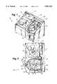
- FIG. 1is an isometric view of an autotransfusion machine incorporating the separator bowl clamping system of the present invention.
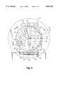
- FIG. 2is a top plan view of the machine shown in FIG. 1.
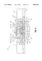
- FIG. 3is an enlarged fragmentary section taken along line 3--3 of FIG. 2.
- FIG. 4is a further enlarged fragmentary section taken along line 4--4 of FIG. 3.
- FIG. 5is a section taken along line 5--5 of FIG. 4 showing the pivot arms in a locking position.
- FIG. 6is a section similar to FIG. 5 showing the pivot arms in an unlocked position.
- FIG. 7is a enlarged fragmentary section taken along line 7--7 of FIG. 4 with the bowl being clamped by the collar in the machine.
- FIG. 8is a fragmentary section similar to FIG. 7 with the collar being slightly loosened relative to its position in FIG. 7.
- FIG. 9is a fragmentary section similar to FIGS. 7 and 8 showing the collar in an open position from which the separator bowl can be removed from the machine.
- FIG. 10is a fragmentary exploded isometric showing the various components of the system for securing or clamping a separator bowl in the machine of FIG. 1.
- FIG. 11is an enlarged fragmentary isometric of a portion of the bowl support plate illustrating the relation of a tine form therein relative to the remainder of the plate.
- FIG. 12is a fragmentary section taken along line 12--12 of FIG. 11.
- FIG. 1shows an autotransfusion machine 12 having a left portion 14 and a right portion 16.
- the left portionincludes a pump 18 and valve means 20 for selectively delivering blood through tubing 21 to a separator bowl 22 (FIG. 3) on the right portion 16 of the machine.
- a control panel 24utilizing touch screen capability is also positioned on the left portion 14 and controls electronic circuitry (not shown) within the machine for operating the various components of the machine.
- the pump 18selectively delivers and removes blood or components thereof from the separator bowl 22 through use of the valves 20 that are electronically controlled.
- the sequence of operationmay be of the type described in U.S. Pat. No. 4,668,214 to Reeder, which is hereby incorporated by reference, even though the machine can be operated, with predesigned circuitry, in accordance with any desirable procedure known to those in the art.
- the right portion 16 of the machine, where the separator bowl 22 is mounted,includes a clear cover 26 pivoted along a back edge 28 to the shell 30 of the machine.
- the coveris selectively clamped in the closed position of FIG. 1 by a latch 32 on the shell at the front edge of the cover.
- the coveris always latched in the closed position but to insert or remove a separator bowl from a cavity 34 defined in the right portion of the machine, the clear cover is unlatched at the forward edge and pivoted about the rear edge into an open position.
- the right portion 16 of the machineincludes a well 36 having a circular peripheral bottom wall 38 and a raised center hub 40 to which an electric motor 42 is secured underneath.
- the peripheral bottom wallmay have a drain hole (not shown) in communication therewith to drain fluids that may accumulate or result from an accident wherein fluids within the separator bowl are released into the well.
- the separator bowl 22as best seen in FIG. 3, includes a generally bell-shaped main body 44 of substantially hollow construction with a bearing 46 disposed in the top of the body that rotatably receives a shaft (not seen) to which a stabilizing arm 48 can be releasably connected.
- the stabilizing armis anchored to a rear wall 50 of the well 36 and has a conventional mechanism 52 for gripping the shaft so that the main body of the separator bowl can be rotated about the shaft.
- the basic components of the bowl 22 as well as the tubing 21 for delivering blood to and removing blood or its components from the bowlare well known in the art. An example would be a bowl of the type currently sold and marketed by the assignee of the present application under Model BT225E.
- the bottom edge of the bowlhas been modified from conventional bowls of the type identified above, and includes a lower cap 54 that defines an enlarged circumferential protrusion at the base of the bowl.
- the cap 54is designed to accommodate the gripping thereof by the clamping system of the present invention.
- the capis of generally shallow cylindrical configuration having a beveled upper surface 56 with an outwardly protruding circumferential rim that defines a relatively sharp circular edge 58. This edge, as will become more apparent later, provides a mechanism by which the bowl 22 can be centered within the well 36 for vibration free rotation.
- the bowl clamping system 60 of the present inventionis probably best seen in FIGS. 3 and 10 to include a disk-shaped rotating or base plate 62, a split ring or collar 64 loosely seated on the base plate, a bowl support plate 66 positioned within the collar and adapted to secure the collar to the base plate, a housing 67 around the collar and a clamp assembly 68 for selectively securing the cap 54 of the separator bowl 22 within the collar 64.
- the entire clamping systemis rotated by the electric motor 42 mounted beneath the hub 40 of the well 36.
- the motoris secured to the hub by fasteners 70 such that the driveshaft 72 of the motor projects upwardly through a circular opening 74 in the hub.
- the driveshaft 72as seen in FIG.
- the couplerincludes alternating metal 78 and rubber 79 rings which are compressed together by four axially extending fasteners 80 that extend down through holes in the various rings of the coupler while being threadedly received in the lowermost metal ring 78. It will be appreciated that when the fasteners 80 are tightened, the metal rings 78 compress the rubber rings 79 therebetween causing the rubber rings to expand radially inwardly and outwardly. The radially inward expansion causes the coupler 76 to grip the driveshaft 72 of the motor.
- the coupler 76is positioned within a driven collar 82 which has an internal diameter approximating that of the outer diameter of the coupler such that the radially outward expansion of the coupler causes the rubber rings 79 to grip the inner wall 84 of the driven collar.
- the driven collarcan be selectively rotated by the electric motor 42 in any given sequence or speed through the coupler which couples the motor driveshaft to the driven collar.
- the driven collar 82is in turn secured to the underside of the base plate 62 with three circumferentially spaced fasteners 86 so that the base plate rotates in unison with the driven collar about the rotational axis of the driveshaft 72.
- the base platehas a central depressed circular region 88 in which the bowl support plate 66 is positively secured with three pair of circumferentially spaced fasteners 90.
- the split ring or collar 64is positioned on the raised outer ring-like circumference 92 of the base plate (FIG. 3).
- the bowl support platehas an interrupted raised radially directed peripheral lip 94 around its circumference adapted to support a separator bowl 22 and three circumferentially spaced tines 95 adapted to cooperate with the collar in a manner to be described hereafter to secure the collar to the base plate.
- the collar 64is of generally split-ring configuration having upper and lower radially inwardly directed circumferential lips 96 and 98 respectively defining a channel 100 therebetween adapted to receive the cap 54 of the separator bowl.
- the collar 64also has two enlarged ends defining blocks 102 (FIG. 10), each with a vertical cylindrical passage 104 therethrough.
- a lateral slot 106 in each blockcommunicates with the cylindrical passage for a purpose to be described later.
- the collar 64is made of spring metal, such as aluminum or steel, and assumes a normal at-rest position as illustrated in FIG. 10 wherein the block ends 102 are spaced a predetermined distance.
- the block endscan be moved toward each other against the bias of the collar thereby reducing the effective circumference of the collar.
- the maximum effective circumference of the collaras shown in FIG. 10, with the collar in its normal or at rest position, is sufficient to allow the cap 54 of the separator bowl to be inserted therein while the retracted or reduced effective circumference obtained by moving the ends of the collar toward each other is comparable to the circumference of the cap. In this manner the cap can be encaptured within the channel 100 of the collar when securing the bowl to the autotransfusion machine 12 as seen in FIG. 3.
- the upper circumferential lip 96 of the collar 64defines a first or upper beveled surface 108
- the lower lip 98defines a shoulder 110 as well as a second beveled surface 112 as is best seen in FIG. 7 through 9.
- the beveled surfaces 108 and 112 on the collarcooperate with the bowl support plate 66 and the separator bowl 22 in centering the collar relative to the motor drive shaft 72 and securing it to the bowl support plate 66 as well as centering the bowl relative to the driveshaft to prevent vibrations.
- the three equally circumferentially spaced tines 95are defined between parallel radial slots 116 formed in the bowl support plate. While the bowl support plate is made of a rigid metal, the tines, due to their relatively narrow width, have a slight degree of flexibility relative to the remainder of the plate and are disposed slightly lower than the remainder of the plate as shown in FIGS. 7 through 9, 11 and 12.
- the elevated peripheral lip 94 of the bowl support plateis stepped in cross-section, as best seen in FIGS. 7 through 9, so as to define a large diameter upper region 118 with an outer, lower edge 124 an intermediate, diameter middle region 120 and a small diameter lower region 122.
- the lower edge 124 of the upper region 118 on each tineis aligned with the lower beveled surface 112 on the collar so as to operatively cooperate therewith in a manner to be described later.
- the sharp ring-like edge 58 on the cap 54 of the separator bowl 22, as best seen in FIGS. 7 through 9,is aligned with the upper beveled surface 108 on the collar for operative cooperation therewith when the bowl is seated on the bowl support plate 66.
- the bowlis first positioned within the collar 64 with the block ends 102 of the collar in the separated at rest positions and with the bowl seated upon the elevated lip 94 of the bowl support plate 66. This positioning is illustrated in FIG. 9.
- the channel 100 within the collaris moved toward the cap of the separator bowl as well as the bowl support plate until the upper beveled surface 108 of the collar engages the sharp ring-like edge 58 on the bowl cap and the lower circumferential edge 124 of the upper region 118 of each tine 95 on the bowl support plate engages the lower beveled surface 112 on the collar as shown in FIG. 8.
- the collarfurther reduces the effective circumference of the collar causing the lower edge 124 of the upper region 118 of each tine 95 to slide slightly up the lower beveled surface 112 of the collar.
- each tineas cams or yieldingly urges the collar 64 downwardly thereby gripping the lower lip 98 of the collar between the bowl support plate 66 and the base plate 62.
- This camming of the collardownwardly positively secures the collar relative to the base plate and the bowl support plate but also centers the collar relative to the axis of rotation of the base plate and bowl support plate to evenly distribute the weight of these components about the axis of rotation. It should be appreciated that only the tines 95 on the bowl support plate engage the collar since they are disposed lower than the remainder of the bowl support plate.
- the bowl 22becomes centered within the collar 64 due to the engagement of the sharp circular edge 58 of the bowl riding along the upper beveled surface 108 which in turn urges the separator bowl downwardly into tight engagement with the bowl support plate 66.
- the collar 64when the collar 64 is retracted, or reduced in effective circumference, not only is the separator bowl 22 centered and positively gripped by the collar so that the bowl will move in unison with the bowl support plate 66, but the collar itself is centered relative to the bowl support plate so that the mass of the rotating components are substantially evenly distributed about the axis of rotation to minimize vibration during operation of the machine.
- the clamp assembly 68 for selectively moving the collar 64 between the expanded and retracted positionsis probably best seen in FIG. 10 to include a main body 126 that is slidably disposed within square openings 128 in the base plate and a pair of levers or pivot arms 130 that are operatively connected to the main body and to the ends of the collar such that sliding vertical movement of the main body in the square openings 128 affects movement of the block ends 102 of the collar toward and away from each other.
- the clamp assemblyfurther includes an auxiliary lock plate 132 pivotally mounted on the main body 126 which functions as a safety lock in assuring that the collar remains in a retracted position during operation of the autotransfusion machine 12.
- the main body 126can be seen to be of generally inverted U-shaped configuration, of substantially square cross-section and defines an upper horizontal leg 134 and a pair of depending legs 136.
- the depending legsare adapted to slide vertically within the square openings 128 provided in the base plate 62 adjacent the perimeter thereof.
- Both the horizontal leg 134 and the depending legs 136have slots 138 therethrough to accommodate positioning and movement of the pivot arms 130.
- the pivot armsare of inverted T-shaped configuration and define a main arm 140 and a cross arm 142 with the cross arm forming a perpendicular extension from the base of the main arm.
- the upper free end of the main armhas a beveled surface 144 for a purpose to be described later.
- each cross arm 142is pivotally connected with a pivot pin 148 to an associated depending leg 136 of the main body within the slot 138 formed in the depending leg.
- the inner end 150 of each cross armis pivotally connected to a connector cylinder 152 (FIGS. 5, 6 and 10) that is secured to the collar.
- the connector cylindershave a relatively large upper cylindrical body 154, a further enlarged intermediate disk 156 and a relatively small depending guide pin 158.
- Each cylindrical body 154 of the connector cylinderis friction fit or otherwise secured within the cylindrical passage 104 on an end block 102 at one end of the collar and has a slot 160 formed therein that is aligned with the slot 106 in the associated end block.
- a pivot pin 161 in the slot 160pivotally connects the connector cylinder to the cross arm 142.
- the intermediate disk 156 of the connector cylinderis slidably seated on a thrust washer 159 within a substantially ovular recess 162 formed in the upper surface of the base plate 62 adjacent to one of the square openings 128.
- a substantially ovular recess 162formed in the upper surface of the base plate 62 adjacent to one of the square openings 128.
- a smaller substantially ovular opening 164extends through the base of each recess 162 and is adapted to slidably receive the guide pin 158 of an associated connector cylinder. Accordingly, the connector cylinders 152 are seated within the substantially ovular recesses on the base plate and protrude upwardly into an associated end block on the collar thereby desirably positioning the collar on the base plate.
- FIGS. 5 and 6The operation of the clamp assembly 68 is best illustrated in FIGS. 5 and 6 with FIG. 6 showing the clamp assembly in the open position such that the collar 64 is fully expanded to receive the separator bowl 22.
- the inverted U-shaped main body 126is raised to its maximum extent which as will be seen tilts the main arms 140 of the inverted T-shaped pivot arms 130 toward each other such that the beveled surface 144 of each main arm engages an abutment surface 166 on a central block 168 defined between the slots 138 in the horizontal leg 134 of the main body.
- the end blocks 102 of the collar 64are separated preferably at their normal or at-rest position so that they are not biased in either direction by the spring metal from which the collar is made.
- connection of the cross arms of the pivot arms to the depending legs 136 of the main body at pivot pins 148is positioned lower than or beneath the plane of the connection of the cross arms to the connector cylinders 152 at pivot pins 161.
- the auxiliary lock plate 132is a substantially rectangular plate connected by a pivot pin 164 to a sleeve 166 on the upper inner edge of the horizontal leg 134 of the main body.
- the lock platecan thereby be pivoted from an unlocking radially inwardly directed position, as shown in FIG. 10, to a locking radially outwardly directed position, as shown in FIG. 5. In the radially outwardly directed position of FIG.
- the auxiliary lock platelies across the top of the horizontal leg 134 and is disposed between the main arms 140 of each pivot arm thereby preventing the main arms from being moved closer to each other which might otherwise allow the collar 64 to release the separator bowl 22.
- the auxiliary lockthereby functions as a safety or backup lock to the overcenter lock already established in the assembly. It is further important to note that rotation of the clamp assembly 68 through centrifugal force encourages the auxiliary lock plate arm to remain in its radially outwardly directed locking position.
- the housing 67 for the clamping system of the present inventionas probably best seen in FIGS. 3 and 10, is of circular configuration and of substantially inverted L-shaped cross-section.
- the housingis supported upon the base plate 62 so as to overly and substantially enclose the collar 64.
- the housingis secured to the base plate with suitable fasteners 168 (FIG. 10) and cooperates with the bowl support plate 66 in assuring confinement of the collar adjacent to the base plate.
- the housingincludes a rectangular slot 170 through which the main body 126 of the clamp assembly protrudes and diametrically opposite that slot, on the top of the housing, a counterweight 172, as seen in FIG. 3, is provided to keep the entire assembly in balance thereby avoiding vibration during operation of the machine.
Landscapes
- Centrifugal Separators (AREA)
Abstract
Description
Claims (17)
Priority Applications (1)
| Application Number | Priority Date | Filing Date | Title |
|---|---|---|---|
| US08/790,076US5851169A (en) | 1996-01-31 | 1997-01-28 | Rotary plate and bowl clamp for blood centrifuge |
Applications Claiming Priority (2)
| Application Number | Priority Date | Filing Date | Title |
|---|---|---|---|
| US1094496P | 1996-01-31 | 1996-01-31 | |
| US08/790,076US5851169A (en) | 1996-01-31 | 1997-01-28 | Rotary plate and bowl clamp for blood centrifuge |
Publications (1)
| Publication Number | Publication Date |
|---|---|
| US5851169Atrue US5851169A (en) | 1998-12-22 |
Family
ID=26681785
Family Applications (1)
| Application Number | Title | Priority Date | Filing Date |
|---|---|---|---|
| US08/790,076Expired - LifetimeUS5851169A (en) | 1996-01-31 | 1997-01-28 | Rotary plate and bowl clamp for blood centrifuge |
Country Status (1)
| Country | Link |
|---|---|
| US (1) | US5851169A (en) |
Cited By (22)
| Publication number | Priority date | Publication date | Assignee | Title |
|---|---|---|---|---|
| US20040055947A1 (en)* | 2002-09-23 | 2004-03-25 | Michael Appel | Clamping-hook ring |
| US20040236262A1 (en)* | 2002-06-14 | 2004-11-25 | Mcintosh Kevin D. | Multiple ratio fluid dispenser |
| EP1683579A1 (en)* | 2005-01-25 | 2006-07-26 | Jean-Denis Rochat | Disposable device for the continuous separation by centrifugation of a physiological liquid |
| EP1683578A1 (en)* | 2005-01-25 | 2006-07-26 | Jean-Denis Rochat | Centrifugal separator for a physiological liquid, in particular blood |
| USD525890S1 (en)* | 2002-11-15 | 2006-08-01 | Tomy Kogyo Co., Ltd. | Centrifugal separator |
| EP1688183A1 (en)* | 2005-02-03 | 2006-08-09 | Jean-Denis Rochat | Method and disposable device for centrifugal separation of a physiologic liquid |
| US20060253082A1 (en)* | 2005-04-21 | 2006-11-09 | Mcintosh Kevin D | Fluid dispenser |
| EP1800754A1 (en)* | 2005-12-21 | 2007-06-27 | Jean-Denis Rochat | Disposable blood centrifuge |
| US20080124700A1 (en)* | 2006-11-27 | 2008-05-29 | Matteo Fortini | Method and apparatus for controlling the flow rate of washing solution during the washing step in a blood centrifugation bowl |
| US20090305863A1 (en)* | 2008-06-10 | 2009-12-10 | Sorin Group Italia S.R.L. | Securing mechanism, particularly for blood separation centrifuges and the like |
| US8317672B2 (en) | 2010-11-19 | 2012-11-27 | Kensey Nash Corporation | Centrifuge method and apparatus |
| US8394006B2 (en) | 2010-11-19 | 2013-03-12 | Kensey Nash Corporation | Centrifuge |
| US8469871B2 (en) | 2010-11-19 | 2013-06-25 | Kensey Nash Corporation | Centrifuge |
| US8556794B2 (en) | 2010-11-19 | 2013-10-15 | Kensey Nash Corporation | Centrifuge |
| US20140134082A1 (en)* | 2007-10-29 | 2014-05-15 | Panasonic Corporation | Analysis device, and analysis apparatus and method using the same |
| US8870733B2 (en) | 2010-11-19 | 2014-10-28 | Kensey Nash Corporation | Centrifuge |
| US9308314B2 (en) | 2011-04-08 | 2016-04-12 | Sorin Group Italia S.R.L. | Disposable device for centrifugal blood separation |
| CN106345620A (en)* | 2016-11-09 | 2017-01-25 | 郭涛 | Blood component separator and automatic plug breaking part thereof |
| US10039876B2 (en) | 2014-04-30 | 2018-08-07 | Sorin Group Italia S.R.L. | System for removing undesirable elements from blood using a first wash step and a second wash step |
| US10125345B2 (en) | 2014-01-31 | 2018-11-13 | Dsm Ip Assets, B.V. | Adipose tissue centrifuge and method of use |
| WO2022109612A1 (en)* | 2020-11-19 | 2022-05-27 | Life Technologies Corporation | Centrifugal separators and skid for separating biocomponents and methods of use |
| US12337097B2 (en) | 2010-11-19 | 2025-06-24 | Dsm Ip Assets B.V. | Centrifuge |
Citations (15)
| Publication number | Priority date | Publication date | Assignee | Title |
|---|---|---|---|---|
| US3317127A (en)* | 1945-03-02 | 1967-05-02 | Little Inc A | Centrifuge |
| US3581981A (en)* | 1945-03-02 | 1971-06-01 | Cryogenic Technology Inc | Centrifuge chuck |
| US3706412A (en)* | 1971-07-28 | 1972-12-19 | Haemonetics Corp | Pressure-actuated centrifuge chuck and centrifuge incorporating the same |
| US3785549A (en)* | 1972-07-31 | 1974-01-15 | Haemonetics Corp | Centrifuge chuck for disposable, snap-in centrifuge rotor |
| US4086924A (en)* | 1976-10-06 | 1978-05-02 | Haemonetics Corporation | Plasmapheresis apparatus |
| US4668214A (en)* | 1986-06-09 | 1987-05-26 | Electromedics, Inc. | Method of washing red blood cells |
| US4684361A (en)* | 1985-10-11 | 1987-08-04 | Cardiovascular Systems, Inc. | Centrifuge |
| US4692136A (en)* | 1985-10-11 | 1987-09-08 | Cardiovascular Systems Inc. | Centrifuge |
| US4718888A (en)* | 1986-03-10 | 1988-01-12 | Cardiovascular Systems, Inc. | Centrifuge bowl mount |
| US4795419A (en)* | 1985-10-11 | 1989-01-03 | Kardiothor, Inc. | Centrifuge |
| US4838849A (en)* | 1987-02-10 | 1989-06-13 | Dideco S.P.A. | Chuck device for holding a cell for the centrifugation of blood |
| US5062826A (en)* | 1989-07-14 | 1991-11-05 | Marco Mantovani | Device for locking a blood centrifugation cell on a chuck |
| US5158407A (en)* | 1989-09-11 | 1992-10-27 | Otto Zettl | Device for the connection of two tool portions of machine tools |
| US5591113A (en)* | 1994-10-31 | 1997-01-07 | Cobe Laboratories, Inc. | Centrifugally assisted centrifuge bowl mount |
| US5658231A (en)* | 1995-09-21 | 1997-08-19 | Haemonetics Corporation | Mechanism for securing a separation bowl to a mechanical chuck |
- 1997
- 1997-01-28USUS08/790,076patent/US5851169A/ennot_activeExpired - Lifetime
Patent Citations (15)
| Publication number | Priority date | Publication date | Assignee | Title |
|---|---|---|---|---|
| US3317127A (en)* | 1945-03-02 | 1967-05-02 | Little Inc A | Centrifuge |
| US3581981A (en)* | 1945-03-02 | 1971-06-01 | Cryogenic Technology Inc | Centrifuge chuck |
| US3706412A (en)* | 1971-07-28 | 1972-12-19 | Haemonetics Corp | Pressure-actuated centrifuge chuck and centrifuge incorporating the same |
| US3785549A (en)* | 1972-07-31 | 1974-01-15 | Haemonetics Corp | Centrifuge chuck for disposable, snap-in centrifuge rotor |
| US4086924A (en)* | 1976-10-06 | 1978-05-02 | Haemonetics Corporation | Plasmapheresis apparatus |
| US4684361A (en)* | 1985-10-11 | 1987-08-04 | Cardiovascular Systems, Inc. | Centrifuge |
| US4692136A (en)* | 1985-10-11 | 1987-09-08 | Cardiovascular Systems Inc. | Centrifuge |
| US4795419A (en)* | 1985-10-11 | 1989-01-03 | Kardiothor, Inc. | Centrifuge |
| US4718888A (en)* | 1986-03-10 | 1988-01-12 | Cardiovascular Systems, Inc. | Centrifuge bowl mount |
| US4668214A (en)* | 1986-06-09 | 1987-05-26 | Electromedics, Inc. | Method of washing red blood cells |
| US4838849A (en)* | 1987-02-10 | 1989-06-13 | Dideco S.P.A. | Chuck device for holding a cell for the centrifugation of blood |
| US5062826A (en)* | 1989-07-14 | 1991-11-05 | Marco Mantovani | Device for locking a blood centrifugation cell on a chuck |
| US5158407A (en)* | 1989-09-11 | 1992-10-27 | Otto Zettl | Device for the connection of two tool portions of machine tools |
| US5591113A (en)* | 1994-10-31 | 1997-01-07 | Cobe Laboratories, Inc. | Centrifugally assisted centrifuge bowl mount |
| US5658231A (en)* | 1995-09-21 | 1997-08-19 | Haemonetics Corporation | Mechanism for securing a separation bowl to a mechanical chuck |
Cited By (58)
| Publication number | Priority date | Publication date | Assignee | Title |
|---|---|---|---|---|
| US7604626B2 (en) | 2002-06-14 | 2009-10-20 | Arteriocyte Medical Systems, Inc. | Multiple ratio fluid dispenser |
| US20040236262A1 (en)* | 2002-06-14 | 2004-11-25 | Mcintosh Kevin D. | Multiple ratio fluid dispenser |
| US7883501B2 (en) | 2002-06-14 | 2011-02-08 | Arteriocyte Medical Systems, Inc. | Multiple ratio fluid dispenser |
| US20090306623A1 (en)* | 2002-06-14 | 2009-12-10 | Arteriocyte Medical Systems, Inc. | Multiple ratio fluid dispenser |
| US6761821B2 (en)* | 2002-09-23 | 2004-07-13 | Weatherford/Lamb, Inc. | Clamping-hook ring |
| US20040055947A1 (en)* | 2002-09-23 | 2004-03-25 | Michael Appel | Clamping-hook ring |
| USD525890S1 (en)* | 2002-11-15 | 2006-08-01 | Tomy Kogyo Co., Ltd. | Centrifugal separator |
| US20080132397A1 (en)* | 2005-01-25 | 2008-06-05 | Jean-Denis Rochat | Centrifugal Separator For a Physiological Fluid, Particularly Blood |
| WO2006079238A1 (en)* | 2005-01-25 | 2006-08-03 | Jean-Denis Rochat | Disposable device for the continuous centrifugal separation of a physiological fluid |
| WO2006079237A1 (en) | 2005-01-25 | 2006-08-03 | Jean-Denis Rochat | Centrifugal separator for a physiological fluid, particularly blood |
| EP1683578A1 (en)* | 2005-01-25 | 2006-07-26 | Jean-Denis Rochat | Centrifugal separator for a physiological liquid, in particular blood |
| US20080153686A1 (en)* | 2005-01-25 | 2008-06-26 | Jean-Denis Rochat | Disposable Device for the Continuous Centrifugal Separation of a Physiological Fluid |
| EP1683579A1 (en)* | 2005-01-25 | 2006-07-26 | Jean-Denis Rochat | Disposable device for the continuous separation by centrifugation of a physiological liquid |
| US8070664B2 (en)* | 2005-01-25 | 2011-12-06 | Jean-Denis Rochat | Disposable device for the continuous centrifugal separation of a physiological fluid |
| US8348823B2 (en) | 2005-01-25 | 2013-01-08 | Jean-Denis Rochat | Disposable device for the continuous centrifugal separation of a physiological fluid |
| EP1688183A1 (en)* | 2005-02-03 | 2006-08-09 | Jean-Denis Rochat | Method and disposable device for centrifugal separation of a physiologic liquid |
| WO2006081699A1 (en)* | 2005-02-03 | 2006-08-10 | Jean-Denis Rochat | Method and disposable device for blood centrifugal separation |
| US8088099B2 (en) | 2005-04-21 | 2012-01-03 | Arteriocyte Medical Systems, Inc. | Fluid dispenser |
| US20060253082A1 (en)* | 2005-04-21 | 2006-11-09 | Mcintosh Kevin D | Fluid dispenser |
| US20100076399A1 (en)* | 2005-04-21 | 2010-03-25 | Arteriocyte Medical Systems, Inc. | Fluid dispenser |
| US7635343B2 (en) | 2005-04-21 | 2009-12-22 | Arteriocyte Medical Systems, Inc. | Fluid dispenser |
| WO2007071086A1 (en) | 2005-12-21 | 2007-06-28 | Jean-Denis Rochat | Disposable device for centrifugation of blood |
| US20080264841A1 (en)* | 2005-12-21 | 2008-10-30 | Jean-Denis Rochat | Disposable Device for Centrifugation of Blood |
| US8070666B2 (en) | 2005-12-21 | 2011-12-06 | Jean-Denis Rochat | Disposable device for centrifugation of blood |
| EP1800754A1 (en)* | 2005-12-21 | 2007-06-27 | Jean-Denis Rochat | Disposable blood centrifuge |
| US8506825B2 (en) | 2006-11-27 | 2013-08-13 | Sorin Group Italia S.R.L. | Method and apparatus for controlling the flow rate of washing solution during the washing step in a blood centrifugation bowl |
| US20080124700A1 (en)* | 2006-11-27 | 2008-05-29 | Matteo Fortini | Method and apparatus for controlling the flow rate of washing solution during the washing step in a blood centrifugation bowl |
| US9404912B2 (en)* | 2007-10-29 | 2016-08-02 | Panasonic Healthcare Holdings Co., Ltd. | Analysis device driving apparatus |
| US20140134082A1 (en)* | 2007-10-29 | 2014-05-15 | Panasonic Corporation | Analysis device, and analysis apparatus and method using the same |
| US8262552B2 (en)* | 2008-06-10 | 2012-09-11 | Sorin Group Italia S.R.L. | Securing mechanism, particularly for blood separation centrifuges and the like |
| US7993257B2 (en)* | 2008-06-10 | 2011-08-09 | Sorin Group Italia S.R.L. | Securing mechanism, particularly for blood separation centrifuges and the like |
| US20090305863A1 (en)* | 2008-06-10 | 2009-12-10 | Sorin Group Italia S.R.L. | Securing mechanism, particularly for blood separation centrifuges and the like |
| US8485957B2 (en)* | 2008-06-10 | 2013-07-16 | Sorin Group Italia S.R.L. | Securing mechanism, particularly for blood separation centrifuges and the like |
| US10646884B2 (en) | 2010-11-19 | 2020-05-12 | Dsm Ip Assets B.V. | Centrifuge |
| US8974362B2 (en) | 2010-11-19 | 2015-03-10 | Kensey Nash Corporation | Centrifuge |
| US8556794B2 (en) | 2010-11-19 | 2013-10-15 | Kensey Nash Corporation | Centrifuge |
| US8562501B2 (en) | 2010-11-19 | 2013-10-22 | Kensey Nash Corporation | Methods for separating constituents of biologic liquid mixtures |
| US8617042B2 (en) | 2010-11-19 | 2013-12-31 | Kensey Nash Corporation | Methods for separating constituents of biologic liquid mixtures |
| US8485958B2 (en) | 2010-11-19 | 2013-07-16 | Kensey Nash Corporation | Systems and methods for separating constituents of biologic liquid mixtures |
| US8747291B2 (en) | 2010-11-19 | 2014-06-10 | Kensey Nash Corporation | Methods for separating constituents of biologic liquid mixtures |
| US8758211B2 (en) | 2010-11-19 | 2014-06-24 | Kensey Nash Corporation | Centrifuge |
| US8870733B2 (en) | 2010-11-19 | 2014-10-28 | Kensey Nash Corporation | Centrifuge |
| US8394006B2 (en) | 2010-11-19 | 2013-03-12 | Kensey Nash Corporation | Centrifuge |
| US9114408B2 (en) | 2010-11-19 | 2015-08-25 | Kensey Nash Corporation | Centrifuge |
| US8317672B2 (en) | 2010-11-19 | 2012-11-27 | Kensey Nash Corporation | Centrifuge method and apparatus |
| US8469871B2 (en) | 2010-11-19 | 2013-06-25 | Kensey Nash Corporation | Centrifuge |
| US12337097B2 (en) | 2010-11-19 | 2025-06-24 | Dsm Ip Assets B.V. | Centrifuge |
| US9987638B2 (en) | 2010-11-19 | 2018-06-05 | Dsm Ip Assets, B.V. | Centrifuge |
| US11167292B2 (en) | 2010-11-19 | 2021-11-09 | Dsm Ip Assets B.V. | Centrifuge |
| US9308314B2 (en) | 2011-04-08 | 2016-04-12 | Sorin Group Italia S.R.L. | Disposable device for centrifugal blood separation |
| US10711239B2 (en) | 2014-01-31 | 2020-07-14 | Dsm Ip Assets B.V. | Adipose tissue centrifuge and method of use |
| US10125345B2 (en) | 2014-01-31 | 2018-11-13 | Dsm Ip Assets, B.V. | Adipose tissue centrifuge and method of use |
| US11549094B2 (en) | 2014-01-31 | 2023-01-10 | Dsm Ip Assets B.V. | Adipose tissue centrifuge and method of use |
| US12018244B2 (en) | 2014-01-31 | 2024-06-25 | Dsm Ip Assets B.V. | Adipose tissue centrifuge and method of use |
| US10293098B2 (en) | 2014-04-30 | 2019-05-21 | Sorin Group Italia S.R.L. | System for removing undesirable elements from blood using a first wash step and a second wash step |
| US10039876B2 (en) | 2014-04-30 | 2018-08-07 | Sorin Group Italia S.R.L. | System for removing undesirable elements from blood using a first wash step and a second wash step |
| CN106345620A (en)* | 2016-11-09 | 2017-01-25 | 郭涛 | Blood component separator and automatic plug breaking part thereof |
| WO2022109612A1 (en)* | 2020-11-19 | 2022-05-27 | Life Technologies Corporation | Centrifugal separators and skid for separating biocomponents and methods of use |
Similar Documents
| Publication | Publication Date | Title |
|---|---|---|
| US5851169A (en) | Rotary plate and bowl clamp for blood centrifuge | |
| US5919125A (en) | Centrifuge bowl for autologous blood salvage | |
| JP3577444B2 (en) | Blood processing centrifuge bowl and method for collecting plasma fraction from whole blood | |
| JP4276431B2 (en) | Cassette with integrated separation device | |
| CA2206599C (en) | Method and device for separating fibrin i from blood plasma | |
| US5547591A (en) | Method for separating a blood material into blood components by centrifugation, and centrifugal apparatus | |
| JP5523418B2 (en) | Platelet-rich plasma concentration apparatus and concentration method | |
| AU652888B2 (en) | Centrifugal processing system with direct access drawer | |
| US7186231B2 (en) | Blood component collection method | |
| CA1316883C (en) | Continuous blood centrifugation cell | |
| JP2001505083A (en) | In particular, a connection device between a container having a stopper member that can be penetrated and a syringe | |
| EP2515966B1 (en) | Methods and apparatus for collection of filtered blood components, in particular red blood cells | |
| US20080128367A1 (en) | Method and Disposable Device For Blood Centrifugal Separation | |
| US20100081196A1 (en) | Method for Separating a Volume of Whole Blood Into At Least Three Components | |
| CA2642653A1 (en) | Blood component processing system, apparatus and method | |
| CA2112886A1 (en) | Centrifugal separator | |
| US5976388A (en) | Method and apparatus for autologous blood salvage | |
| EP3322459B1 (en) | System and method for removing fat from salvaged blood | |
| EP1009538B1 (en) | Mechanism for fixing a blood centrifuge bowl to a rotating spindle | |
| EP3747481B1 (en) | Systems and methods for harvesting mncs as part of a plasma collection procedure | |
| US5308309A (en) | Securing system for centrifuge chamber | |
| US6210391B1 (en) | Rapid transfer autotransfusion bag and methods related thereto | |
| KR101457583B1 (en) | Autologous transfusion device | |
| JPH0947688A (en) | Centrifugal separation of blood and device thereof | |
| JPH0947689A (en) | Blood centrifugal separation and device thereof |
Legal Events
| Date | Code | Title | Description |
|---|---|---|---|
| AS | Assignment | Owner name:MEDTRONIC ELECTROMEDICS, INC., COLORADO Free format text:ASSIGNMENT OF ASSIGNORS INTEREST;ASSIGNORS:MERESZ, HENRY;GRIFFIN, WAYNE P.;HILL, CLARK M.;AND OTHERS;REEL/FRAME:008408/0910;SIGNING DATES FROM 19970107 TO 19970122 | |
| STCF | Information on status: patent grant | Free format text:PATENTED CASE | |
| FPAY | Fee payment | Year of fee payment:4 | |
| FPAY | Fee payment | Year of fee payment:8 | |
| AS | Assignment | Owner name:ARTERIOCYTE MEDICAL SYSTEMS, INC., OHIO Free format text:ASSIGNMENT OF ASSIGNORS INTEREST;ASSIGNOR:MEDTRONIC, INC.;REEL/FRAME:020362/0735 Effective date:20071024 | |
| FPAY | Fee payment | Year of fee payment:12 | |
| AS | Assignment | Owner name:ESCALATE CAPITAL PARTNERS SBIC I, L.P., TEXAS Free format text:SECURITY INTEREST;ASSIGNOR:ARTERIOCYTE MEDICAL SYSTEMS, INC.;REEL/FRAME:032538/0560 Effective date:20140320 | |
| AS | Assignment | Owner name:COMERICA BANK, MICHIGAN Free format text:SECURITY INTEREST;ASSIGNOR:ARTERIOCYTE MEDICAL SYSTEMS, INC.;REEL/FRAME:034170/0303 Effective date:20141024 | |
| AS | Assignment | Owner name:ARTERIOCYTE MEDICAL SYSTEMS, INC., MASSACHUSETTS Free format text:RELEASE BY SECURED PARTY;ASSIGNOR:ESCALATE CAPITAL PARTNERS SBIC I, L.P.;REEL/FRAME:038113/0976 Effective date:20160324 | |
| AS | Assignment | Owner name:ARTERIOCYTE MEDICAL SYSTEMS MANUFACTURING OF MASSA Free format text:RELEASE BY SECURED PARTY;ASSIGNOR:COMERICA BANK;REEL/FRAME:038381/0895 Effective date:20160401 | |
| AS | Assignment | Owner name:TWIN BROOK CAPITAL PARTNERS, LLC, AS AGENT, ILLINO Free format text:SECURITY INTEREST;ASSIGNOR:ARTERIOCYTE MEDICAL SYSTEMS, INC.;REEL/FRAME:039567/0894 Effective date:20160829 | |
| AS | Assignment | Owner name:ISTO TECHNOLOGIES II, LLC, MISSOURI Free format text:RELEASE BY SECURED PARTY;ASSIGNOR:TWIN BROOK CAPITAL PARTNERS, LLC;REEL/FRAME:065269/0604 Effective date:20231016 |