US5850732A - Low emissions combustion system for a gas turbine engine - Google Patents
Low emissions combustion system for a gas turbine engineDownload PDFInfo
- Publication number
- US5850732A US5850732AUS08/855,210US85521097AUS5850732AUS 5850732 AUS5850732 AUS 5850732AUS 85521097 AUS85521097 AUS 85521097AUS 5850732 AUS5850732 AUS 5850732A
- Authority
- US
- United States
- Prior art keywords
- combustion system
- low emissions
- elongated
- injector tube
- fuel
- Prior art date
- Legal status (The legal status is an assumption and is not a legal conclusion. Google has not performed a legal analysis and makes no representation as to the accuracy of the status listed.)
- Expired - Lifetime
Links
- 238000002485combustion reactionMethods0.000titleclaimsabstractdescription115
- 239000000446fuelSubstances0.000claimsabstractdescription208
- 238000010790dilutionMethods0.000claimsabstractdescription26
- 239000012895dilutionSubstances0.000claimsabstractdescription26
- 239000007789gasSubstances0.000claimsdescription16
- 239000007788liquidSubstances0.000claimsdescription14
- 239000000567combustion gasSubstances0.000claimsdescription4
- 230000003247decreasing effectEffects0.000claimsdescription3
- 238000011144upstream manufacturingMethods0.000claims12
- 239000000203mixtureSubstances0.000abstractdescription9
- 230000009977dual effectEffects0.000description6
- 238000005755formation reactionMethods0.000description4
- VNWKTOKETHGBQD-UHFFFAOYSA-NmethaneChemical compoundCVNWKTOKETHGBQD-UHFFFAOYSA-N0.000description4
- 238000002156mixingMethods0.000description4
- 230000015572biosynthetic processEffects0.000description3
- 238000001816coolingMethods0.000description3
- 238000002347injectionMethods0.000description3
- 239000007924injectionSubstances0.000description3
- ATUOYWHBWRKTHZ-UHFFFAOYSA-NPropaneChemical compoundCCCATUOYWHBWRKTHZ-UHFFFAOYSA-N0.000description2
- 238000010276constructionMethods0.000description2
- 239000003345natural gasSubstances0.000description2
- 230000000087stabilizing effectEffects0.000description2
- 206010016754FlashbackDiseases0.000description1
- 230000003190augmentative effectEffects0.000description1
- 230000002146bilateral effectEffects0.000description1
- 230000001419dependent effectEffects0.000description1
- 239000002283diesel fuelSubstances0.000description1
- -1etc.Substances0.000description1
- 239000003502gasolineSubstances0.000description1
- 239000001294propaneSubstances0.000description1
- 238000010791quenchingMethods0.000description1
- 238000012163sequencing techniqueMethods0.000description1
- 230000006641stabilisationEffects0.000description1
- 238000011105stabilizationMethods0.000description1
- 230000002459sustained effectEffects0.000description1
Images


Classifications
- F—MECHANICAL ENGINEERING; LIGHTING; HEATING; WEAPONS; BLASTING
- F23—COMBUSTION APPARATUS; COMBUSTION PROCESSES
- F23R—GENERATING COMBUSTION PRODUCTS OF HIGH PRESSURE OR HIGH VELOCITY, e.g. GAS-TURBINE COMBUSTION CHAMBERS
- F23R3/00—Continuous combustion chambers using liquid or gaseous fuel
- F23R3/28—Continuous combustion chambers using liquid or gaseous fuel characterised by the fuel supply
- F23R3/286—Continuous combustion chambers using liquid or gaseous fuel characterised by the fuel supply having fuel-air premixing devices
- F—MECHANICAL ENGINEERING; LIGHTING; HEATING; WEAPONS; BLASTING
- F23—COMBUSTION APPARATUS; COMBUSTION PROCESSES
- F23R—GENERATING COMBUSTION PRODUCTS OF HIGH PRESSURE OR HIGH VELOCITY, e.g. GAS-TURBINE COMBUSTION CHAMBERS
- F23R3/00—Continuous combustion chambers using liquid or gaseous fuel
- F23R3/02—Continuous combustion chambers using liquid or gaseous fuel characterised by the air-flow or gas-flow configuration
- F23R3/16—Continuous combustion chambers using liquid or gaseous fuel characterised by the air-flow or gas-flow configuration with devices inside the flame tube or the combustion chamber to influence the air or gas flow
- F—MECHANICAL ENGINEERING; LIGHTING; HEATING; WEAPONS; BLASTING
- F23—COMBUSTION APPARATUS; COMBUSTION PROCESSES
- F23R—GENERATING COMBUSTION PRODUCTS OF HIGH PRESSURE OR HIGH VELOCITY, e.g. GAS-TURBINE COMBUSTION CHAMBERS
- F23R3/00—Continuous combustion chambers using liquid or gaseous fuel
- F23R3/42—Continuous combustion chambers using liquid or gaseous fuel characterised by the arrangement or form of the flame tubes or combustion chambers
Definitions
- This inventionrelates to the general field of combustion systems and more particularly to an improved low emissions combustion system for a gas turbine engine.
- inlet airis continuously compressed, mixed with fuel in an inflammable proportion, and then contacted with an ignition source to ignite the mixture which will then continue to burn.
- the heat energythus released then flows in the combustion gases to a turbine where it is converted to rotary energy for driving equipment such as an electrical generator.
- the combustion gasesare then exhausted to atmosphere after giving up some of their remaining heat to the incoming air provided from the compressor.
- Quantities of air greatly in excess of stoichiometric amountsare normally compressed and utilized to keep the combustor liner cool and dilute the combustor exhaust gases so as to avoid damage to the turbine nozzle and blades.
- primary sections of the combustorare operated near stoichiometric conditions which produce combustor gas temperatures up to approximately four thousand (4,000) degrees Fahrenheit.
- secondary airis admitted which raises the air-fuel ratio and lowers the gas temperatures so that the gases exiting the combustor are in the range of two thousand (2,000) degrees Fahrenheit.
- the low emissions combustion system of the present inventiongenerally includes a generally annular combustor formed from a cylindrical outer liner and a tapered inner liner together with the combustor dome.
- a plurality of tangential fuel injectorsintroduce a fuel/air mixture at the combustor dome end of the annular combustion chamber.
- a generally skirt shaped flow control baffleextends from the tapered inner liner into the annular combustion chamber.
- a plurality of air dilution holes in the tapered inner liner underneath the flow control baffleintroduce dilution air into the annular combustion chamber.
- a plurality of air dilution holes in the cylindrical outer linerintroduces more dilution air downstream from the flow control baffle.
- the fuel injectorsextend through the recuperator housing and into the combustor through an angled tube which extends between the outer recuperator wall and the inner recuperator wall and then through a guide in the cylindrical outer liner of the combustor housing into the interior of the annular combustion chamber.
- the fuel injectorsgenerally comprise an elongated injector tube with the outer end including a coupler having at least one fuel inlet tube. Compressed combustion air is provided to the interior of the elongated injector tube from either holes or slits therein which receive compressed air from the angled tube around the fuel injector which is open to the space between the recuperator housing and the combustor.
- the fuel injectormay include a concentric inner tube within the elongated injector tube and a centering ring, including a plurality of holes, may be disposed in the space between the concentric inner injector tube and the elongated injector tube.
- a centering ring and the holes or slits in the outer injector tubeare possible.
- the discharge end of the outer injector tubemay also include a pilot flame holder or a swirler.
- FIG. 1is a perspective view, partially cut away, of a turbogenerator utilizing the low emissions combustion system of the present invention
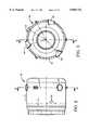
- FIG. 2is a plan view of a combustor housing for the low emissions combustion system of the present invention
- FIG. 3is a sectional view of the combustor housing of FIG. 2 taken along line 3--3 of FIG. 2;
- FIG. 4is a sectional view of the combustor housing of FIG. 3 taken along line 4--4 of FIG. 3;
- FIG. 5is an enlarged sectional view, partially schematic, of an alternate combustor housing for the low emissions combustion system of the present invention
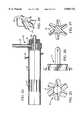
- FIG. 6is an enlarged sectional view of a fuel injector at full power for the low emissions combustion system of the present invention illustrating the passage of the fuel injector through the recuperator housing of the gas turbine engine and into the combustor housing;
- FIG. 7is an enlarged sectional view of a fuel injector at low power for the low emissions combustion system of the present invention illustrating the passage of the fuel injector through the recuperator housing of the gas turbine engine and into the combustor housing;
- FIG. 8is an enlarged portion of the fuel injector tube having elongated slits
- FIG. 9is a section view of the fuel injector tube of FIG. 8 taken along line 9--9 of FIG. 8;
- FIG. 10is an enlarged portion of the alternate fuel injector tube having elongated slits
- FIG. 11is a sectional view of an alternate fuel injector for the low emissions combustion system of the present invention.
- FIG. 12is a sectional view of another alternate fuel injector for the low emissions combustion system of the present invention.
- FIG. 13is a sectional view of yet another alternate fuel injector for the low emissions combustion system of the present invention.
- FIG. 14is a sectional view of still another alternate fuel injector for the low emissions combustion system of the present invention.
- FIG. 15is a sectional view of a further alternate fuel injector for the low emissions combustion system of the present invention.
- FIG. 16is a sectional view of a still further alternate fuel injector for the low emissions combustion system of the present invention.
- FIG. 17is a sectional view of yet a still further alternate fuel injector for the low emissions combustion system of the present invention.
- FIG. 18is a sectional view of another still further alternate fuel injector for the low emissions combustion system of the present invention.
- FIG. 19is a sectional view of a dual fuel injector for the low emissions combustion system of the present invention.
- FIG. 20is a sectional view of an alternate dual fuel injector for the low emissions combustion system of the present invention.
- FIG. 21is a sectional view of another alternate dual fuel injector for the low emissions combustion system of the present invention.
- FIG. 22is a sectional view of yet another alternate dual fuel injector for the low emissions combustion system of the present invention.
- FIG. 23is a sectional view of still another alternate dual fuel injector for the low emissions combustion system of the present invention.
- FIG. 24is a sectional view of a further alternate dual fuel injector for the low emissions combustion system of the present invention.
- FIG. 25is an end view of the swirler of the fuel injectors of FIGS. 11, 15, and 21;
- FIG. 26is a side view of the swirler of FIG. 25;
- FIG. 27is a sectional view of the swirler of FIG. 26 taken along line 27--27 of FIG. 26;
- FIG. 28is an enlarged perspective view of the swirler of FIGS. 25-27.
- the turbogenerator 12utilizing the low emissions combustion system of the present invention is illustrated in FIG. 1.
- the turbogenerator 12generally comprises a permanent magnet generator 20, a power head 21, a combustor 22 and a recuperator (or heat exchanger) 23.
- the permanent magnet generator 20includes a permanent magnet rotor or sleeve 26, having a permanent magnet disposed therein, rotatably supported within a permanent magnet stator 27 by a pair of spaced journal bearings.
- Radial permanent magnet stator cooling fins 28are enclosed in an outer cylindrical sleeve 29 to form an annular air flow passage which cools the permanent magnet stator 27 and thereby preheats the air passing through on its way to the power head 21.
- the power head 21 of the turbogenerator 12includes compressor 30, turbine 31, and bearing rotor 32 through which the tie rod 33 to the permanent magnet rotor 26 passes.
- the compressor 30,having compressor impeller or wheel 34 which receives preheated air from the annular air flow passage in cylindrical sleeve 29 around the permanent magnet stator 27, is driven by the turbine 31 having turbine wheel 35 which receives heated exhaust gases from the combustor 22 supplied with preheated air from recuperator 23.
- the compressor wheel 34 and turbine wheel 35are supported on a bearing shaft or rotor 32 having a radially extending bearing rotor thrust disk 36.
- the bearing rotor 32is rotatably supported by a single journal bearing within the center bearing housing 37 while the bearing rotor thrust disk 36 at the compressor end of the bearing rotor 32 is rotatably supported by a bilateral thrust bearing.
- the recuperator 23includes an annular housing 40 having a heat transfer section 41, an exhaust gas dome 42 and a combustor dome 43. Exhaust heat from the turbine 31 is used to preheat the air before it enters the combustor 22 where the preheated air is mixed with fuel and burned. The combustion gases are then expanded in the turbine 31 which drives the compressor 30 and the permanent magnet rotor 26 of the permanent magnet generator 20 which is mounted on the same shaft as the turbine 31. The expanded turbine exhaust gases are then passed through the recuperator 23 before being discharged from the turbogenerator 12.
- the combustor housing 39 of the combustor 22is illustrated in FIGS. 2-4, and generally comprises a cylindrical outer liner 44 and a tapered inner liner 46 which, together with the combustor dome 43, form a generally expanding annular combustion housing or chamber 39 from the combustor dome 43 to the turbine 31.
- a plurality of fuel injector guides 49(shown as three) position the fuel injectors 14 to tangentially introduce a fuel/air mixture at the combustor dome 43 end of the annular combustion housing 39 along the fuel injector axis or centerline 47.
- This same centerline 47includes an ignitor cap to position an ignitor (not shown) within the combustor housing 39.
- the combustion dome 43is rounded out to permit the swirl pattern from the fuel injectors 14 to fully develop and also to reduce structural stress loads in the combustor.
- a flow control baffle 48extends from the tapered inner liner 46 into the annular combustion housing 39.
- the baffle 48which would be generally skirt-shaped, would extend between one-third and one-half of the distance between the tapered inner liner 46 and the cylindrical outer liner 44.
- Three rows each of a plurality of spaced offset air dilution holes 52, 53, and 54 in the tapered inner liner 46 underneath the flow control baffle 48introduce dilution air into the annular combustion housing 39.
- the first two (2) rows of air dilution holes 52 and 53may be the same size with both, however, smaller than the third row of air dilution holes 54.
- the plurality of holes 50 closest to the flow control baffle 48may be larger and less numerous than the second row of holes 51.
- FIG. 5An alternate combustor housing 39' is illustrated in FIG. 5 and is substantially similar to the combustor housing 39 of FIGS. 2-4 except that the flow control baffle 48' extends between one-half to two-thirds of the distance between the tapered inner liner 46 and cylindrical outer liner 44.
- the low emissions combustor system of the present inventioncan operate on gaseous fuels, such as natural gas, propane, etc., liquid fuels such as gasoline, diesel oil, etc., or can be designed to accommodate either gaseous or liquid fuels.
- gaseous fuelssuch as natural gas, propane, etc.
- liquid fuelssuch as gasoline, diesel oil, etc.
- the fuel injectors of FIGS. 6-18are designed for operation on a single fuel.
- the fuel injectors of FIGS. 19-24have individual inlets for both a gaseous fuel and for a liquid fuel and can operate on whichever fuel would be available.
- Fuelcan be provided individually to each fuel injector 14, or, as shown in FIG. 1, a fuel manifold 15 can be used to supply fuel to all three (3) fuel injectors 14.
- the fuel manifold 15includes a fuel inlet 16 to receive fuel from a fuel source (not shown).
- Flow control valves 17are provided in each of the fuel lines from the manifold 15 to the fuel injectors 14. In order to sustain low power operation, maintain fuel economy and low emissions, the flow control valves 17 can be individually controlled to an on/off position (to separately use any combination of fuel injectors individually) or they can be modulated together.
- the flow control valves 17can be opened by fuel pressure or their operation can be controlled or augmented with a solenoid.
- FIG. 6illustrates the fuel injector 14 extending through the recuperator housing 40 and into the combustor housing 39 through an fuel injector guide 49.
- the fuel injector flange 55is attached to a boss 56 on the outer recuperator wall 57 and extends through an angled tube 58 between the outer recuperator wall 57 and the inner recuperator wall 59.
- the fuel injector 14extends through the fuel injector guide 49 in the cylindrical outer liner 44 of the combustor housing 39 into the interior of the annular combustion housing 39.
- the fuel injectors 14generally comprise an injector tube 61 having an inlet end and a discharge end.
- the inlet end of the injector tube 61includes a coupler 62 having a fuel inlet tube 64 which provides fuel to the injector tube 61.
- the fuelis distributed within the injector tube 61 to be a centering ring 65 having a plurality of spaced openings 66 to permit the passage of fuel. These openings 66 serve to provide a good distribution of the fuel injector tube 61.
- the space between the angled tube 58 and the outer injector tube 61is open to the space between the inner recuperator wall 59 and the cylindrical outer liner 44 of the combustor housing 39. Heated compressed air from the recuperator 23 is supplied to the space between the inner recuperator wall 59 and the cylindrical outer liner 44 of the combustor housing 39 and is thus available to the interior of the angled tube 58.
- a plurality of elongated slits 67 in the injector tube 61 downstream of the centering ring 65provide compressed air from the angled tube 58 to the fuel in the injector tube 61 downstream of the centering ring 65.
- These elongated slitsreceive the compressed air from the angled tube 58 which receives compressed air from the space between the inner recuperator wall 59 and the cylindrical outer liner 44 of the combustor housing 39.
- the downstream face of the centering ring 65can be sloped to help direct the compressed air entering the injector tube 61 in a downstream direction.
- the elongated slits 67are shown in more detail in FIGS. 8 and 9. While the slits 67 generally extend parallel to the axis or centerline of the injector tube 61, they are radially angled, that is the sidewalls of the slits 67 are not radial but rather are angled. This angle will direct the compressed air to enter the injector tube 61 in a generally tangential direction to better mix with and swirl the fuel exiting from the fuel distribution centering ring 65 in the injector tube 61.
- the injector tube 69may include elongated slits 70 which are angled from the axis or centerline of the injector tube 69 as shown in FIG. 10. This will also serve to mix and swirl the fuel exiting from the fuel distribution centering ring 65 in the injector tube 61.
- the flame 70 from the fuel injector 14will be inside the combustor housing 39 as illustrated in FIG. 6.
- the highly premixed fuel and air mixtureleads to quite low NOx levels.
- the poweris cut back and fuel flow is decreased, the flame 71 will flash-back into the injector tube 61 and stabilize in the injector tube 61 as illustrated in FIG. 7.
- the injector tube 61, fuel distribution centering ring 65, and the swirl slits 67together serve to stabilize the flame within the injector tube 61.
- FIG. 7An alternate angled tube 58' is illustrated in FIG. 7.
- This angled tube 58'which extends between the outer recuperator wall 57 and the inner recuperator wall 59 includes a bellows section 68 which can accommodate differential thermal expansion between the angled tube 58' and the recuperator housing 40 through which it extends.
- the injector tube 75includes a row of holes 79 downstream of the fuel distribution centering ring 65 and the discharge end of the fuel injector tube 75 includes a face swirler 77 to promote the mixing of the fuel and air before discharge of the fuel/air mixture into the combustor housing 39 and flame stabilization at the injector exit and within the combustor housing 39.
- This face swirler 77which has a plurality of vanes 78, is shown in more detail in FIGS. 25-27.
- the fuel injector 81includes fuel injector tube 82 having a plurality of holes 79 and then a plurality of elongated slits 67 disposed downstream of the fuel distribution centering ring 65. The position of the holes 79 and slits 67 are reversed in the fuel injector tube 84 of the fuel injector 83 of FIG. 13.
- the fuel injectors 85, 86, 87, and 88 of FIGS. 14-17 respectivelygenerally correspond to the fuel injectors 14, 74, 81, and 83 of FIGS. 6, 11, 12, and 13, respectively, except that the fuel injectors 85, 86, 87, and 88 do not include the fuel distribution centering ring 65 of fuel injectors 14, 17, 81, and 83.
- the only other differenceis that the fuel injector tube 89 of fuel injector 86 includes two (2) rows of a plurality of offset holes 79 and 80 rather than a single row of holes 79 as in fuel injector tube 75 of fuel injector 74.
- Fuel injector 90generally comprises an inner injector tube 91 concentrically disposed within outer injector tube 75.
- the inlet end of the outer injector tube 75includes a coupler 92 having a main fuel inlet tube 93.
- the extension 94 of the inner injector tube 91 outside of the coupler 92provides a secondary or pilot fuel inlet.
- the fuel inlet tube 93provides fuel to the annular space between the inner injector tube 91 and outer injector tube 75, while the extension 94 of the inner injector tube 91 provides fuel to a pilot flame holder 95 at the discharge end of the inner injector tube 91.
- the inner injector tube 91is maintained concentrically within the outer injector tube 75 by fuel distribution centering ring 65 disposed generally midway between the coupler 92 and the pilot flame holder 95.
- the fuel injectors of FIGS. 6-18are specifically designed to use gaseous fuel and certainly would be most advantageously used with a gaseous fuel. Under some circumstances, however, these same fuel injectors could use liquid fuel instead of gaseous fuel. As represented by FIGS. 19-24, these fuel injectors are, however, specifically designed to accommodate either gaseous and liquid fuel depending solely upon fuel availability.
- the fuel injectors 101-105 of FIGS. 19-24each include a fuel injector tube, 82 for FIGS. 19 and 22, 61 for FIGS. 20 and 24, 89 for FIG. 21, and 84 for FIG. 23.
- Each of these fuel injector tubesextend from the coupler 92 which includes a perpendicular fuel inlet tube 97 for gaseous fuel and a concentric fuel inlet tube 98 for liquid fuel.
- Fuel injectors 100 and 101include a concentric inner injector tube 99 extending from fuel distribution centering ring 65 to the concentric fuel inlet tube 98 of coupler 92.
- the fuel injector tube 82 of fuel injector 100includes both offset holes 79 and elongated slits 67 while fuel injector tube 61 of fuel injector 101 only includes elongated slits 67.
- the fuel injector tube 89 of fuel injector 102includes two (2) rows each of a plurality of offset holes 79 and 80 and also a swirler 77 having vanes 78.
- a row of holes 79 and a row of elongated slits 67are included in fuel injector tubes 82 and 84 of fuel injector 103 and 104, respectively, with the slits 67 downstream of the holes 79 in fuel injector tube 82 and vice versa in fuel injector tube 84.
- the fuel injector tube 61 of fuel injector 105includes only a plurality of elongated slits 67.
- the swirler 77is illustrated in FIGS. 25-27.
- Six (6) vanes 78are shown to impart the swirling motion to the fuel/air mixture passing through but the swirler may consist of more or less vanes.
- the swirler 107 of FIG. 28is just a different view of the swirler illustrated in FIGS. 25-27.
- the improved low emissions combustion system of the present inventionemploys a lean premixed combustion zone throughout.
- the present inventionutilizes an annular combustor with tangential injection of a fuel/air mixture in the primary zone followed by the injection of dilution air in a secondary zone.
- the combustoris very large, at least an order of magnitude, when compared to the standard size associated with a given power level. The high mixing and low equivalence ratio will lead to a very low level of NOx formation in the primary zone.
- the lean secondary zoneis formed by flowing air through secondary holes beneath the flow control baffle and also further downstream from the flow control baffle.
- the flow control baffleprevents the establishment of a separate quench zone in the combustor.
- Swirling/impinging jetsare used to form a high degree of turbulence and increase local mixing.
- Low levels of COare obtained because of the low velocities and high residence times in the primary zone which is obtained by use of the oversize combustor with tangential injection.
- the large combustorproduces higher velocities between the combustor and combustor casing which increases the amount of convection cooling to the combustor walls and thus eliminating the need for film cooling which often leads to the formation of CO and HC.
- combustion system of the present inventionachieves low emissions while still employing a relatively simple design and construction.
- Certain of the fuel injectorsare designed to operate on gaseous fuel, others of the fuel injectors are designed to operate on liquid fuel, while some of the fuel injectors are able to function on whatever fuel is available, either gaseous or liquid.
- the vaned swirlersare particularly advantageous in keeping emission levels very low over the entire operating range of the combustion system.
- the pilot flameinstead of a swirler, however, at low power operation the NOx may be somewhat higher.
- the pilot flamewill have a significantly better turn-down as will stabilizing the flame within the injector tube during low power operation. Staging or sequencing of the fuel injectors will also provide a wide range of operating conditions which greatly increases the pattern factor during off loading.
- the low emissions combustion system of the present inventioncan achieve less than 9 ppm V of NMOG, CO, and NOx at 15% O 2 for natural gas at design point.
- a high level of mixing between the fuel and airis obtained in the fuel injector and also in the way that the air is injected into the combustor.
- low emissionscan be obtained in a relatively simple construction, avoiding many of the complexities typically required to obtain low emissions in a gas turbine combustor.
Landscapes
- Engineering & Computer Science (AREA)
- Chemical & Material Sciences (AREA)
- Combustion & Propulsion (AREA)
- Mechanical Engineering (AREA)
- General Engineering & Computer Science (AREA)
Abstract
Description
Claims (60)
Priority Applications (8)
| Application Number | Priority Date | Filing Date | Title |
|---|---|---|---|
| US08/855,210US5850732A (en) | 1997-05-13 | 1997-05-13 | Low emissions combustion system for a gas turbine engine |
| IL12291298AIL122912A (en) | 1997-05-13 | 1998-01-12 | Low emissions combustion system for a gas turbine engine |
| CA002234529ACA2234529A1 (en) | 1997-05-13 | 1998-04-09 | Low emissions combustion system for a gas turbine engine |
| JP10107642AJPH10311539A (en) | 1997-05-13 | 1998-04-17 | Low-emission combustion system for gas turbine engine |
| DE69828916TDE69828916T2 (en) | 1997-05-13 | 1998-05-12 | Low emission combustion system for gas turbine engines |
| EP98303693AEP0878665B1 (en) | 1997-05-13 | 1998-05-12 | Low emissions combustion system for a gas turbine engine |
| US09/168,299US5894720A (en) | 1997-05-13 | 1998-10-07 | Low emissions combustion system for a gas turbine engine employing flame stabilization within the injector tube |
| US09/182,966US6016658A (en) | 1997-05-13 | 1998-10-08 | Low emissions combustion system for a gas turbine engine |
Applications Claiming Priority (1)
| Application Number | Priority Date | Filing Date | Title |
|---|---|---|---|
| US08/855,210US5850732A (en) | 1997-05-13 | 1997-05-13 | Low emissions combustion system for a gas turbine engine |
Related Child Applications (2)
| Application Number | Title | Priority Date | Filing Date |
|---|---|---|---|
| US09/168,299DivisionUS5894720A (en) | 1997-05-13 | 1998-10-07 | Low emissions combustion system for a gas turbine engine employing flame stabilization within the injector tube |
| US09/182,966DivisionUS6016658A (en) | 1997-05-13 | 1998-10-08 | Low emissions combustion system for a gas turbine engine |
Publications (1)
| Publication Number | Publication Date |
|---|---|
| US5850732Atrue US5850732A (en) | 1998-12-22 |
Family
ID=25320623
Family Applications (3)
| Application Number | Title | Priority Date | Filing Date |
|---|---|---|---|
| US08/855,210Expired - LifetimeUS5850732A (en) | 1997-05-13 | 1997-05-13 | Low emissions combustion system for a gas turbine engine |
| US09/168,299Expired - LifetimeUS5894720A (en) | 1997-05-13 | 1998-10-07 | Low emissions combustion system for a gas turbine engine employing flame stabilization within the injector tube |
| US09/182,966Expired - LifetimeUS6016658A (en) | 1997-05-13 | 1998-10-08 | Low emissions combustion system for a gas turbine engine |
Family Applications After (2)
| Application Number | Title | Priority Date | Filing Date |
|---|---|---|---|
| US09/168,299Expired - LifetimeUS5894720A (en) | 1997-05-13 | 1998-10-07 | Low emissions combustion system for a gas turbine engine employing flame stabilization within the injector tube |
| US09/182,966Expired - LifetimeUS6016658A (en) | 1997-05-13 | 1998-10-08 | Low emissions combustion system for a gas turbine engine |
Country Status (6)
| Country | Link |
|---|---|
| US (3) | US5850732A (en) |
| EP (1) | EP0878665B1 (en) |
| JP (1) | JPH10311539A (en) |
| CA (1) | CA2234529A1 (en) |
| DE (1) | DE69828916T2 (en) |
| IL (1) | IL122912A (en) |
Cited By (103)
| Publication number | Priority date | Publication date | Assignee | Title |
|---|---|---|---|---|
| US5894720A (en)* | 1997-05-13 | 1999-04-20 | Capstone Turbine Corporation | Low emissions combustion system for a gas turbine engine employing flame stabilization within the injector tube |
| US6195607B1 (en) | 1999-07-06 | 2001-02-27 | General Electric Company | Method and apparatus for optimizing NOx emissions in a gas turbine |
| EP1130322A1 (en) | 2000-02-24 | 2001-09-05 | Capstone Turbine Corporation | Multi-stage multi-plane combustion system for a gas turbine engine |
| WO2002029225A1 (en) | 2000-10-04 | 2002-04-11 | Capstone Turbine Corporation | Method of shutting-down a turbine engine and system for carrying out said method |
| US6405522B1 (en) | 1999-12-01 | 2002-06-18 | Capstone Turbine Corporation | System and method for modular control of a multi-fuel low emissions turbogenerator |
| US6489692B1 (en) | 1999-12-13 | 2002-12-03 | Capstone Turbine Corporation | Method and apparatus for controlling rotation of magnetic rotor |
| US6513331B1 (en)* | 2001-08-21 | 2003-02-04 | General Electric Company | Preferential multihole combustor liner |
| US6543231B2 (en) | 2001-07-13 | 2003-04-08 | Pratt & Whitney Canada Corp | Cyclone combustor |
| US6664653B1 (en) | 1998-10-27 | 2003-12-16 | Capstone Turbine Corporation | Command and control system for controlling operational sequencing of multiple turbogenerators using a selected control mode |
| US6688111B2 (en)* | 2000-11-14 | 2004-02-10 | Alstom Technology Ltd | Method for operating a combustion chamber |
| US6732531B2 (en)* | 2001-03-16 | 2004-05-11 | Capstone Turbine Corporation | Combustion system for a gas turbine engine with variable airflow pressure actuated premix injector |
| US6845621B2 (en) | 2000-05-01 | 2005-01-25 | Elliott Energy Systems, Inc. | Annular combustor for use with an energy system |
| US6870279B2 (en)* | 1998-01-05 | 2005-03-22 | Capstone Turbine Corporation | Method and system for control of turbogenerator power and temperature |
| US6886342B2 (en) | 2002-12-17 | 2005-05-03 | Pratt & Whitney Canada Corp. | Vortex fuel nozzle to reduce noise levels and improve mixing |
| US20070214790A1 (en)* | 2006-03-17 | 2007-09-20 | Siemens Power Generation, Inc. | Removable diffusion stage for gas turbine engine fuel nozzle assemblages |
| US20070256416A1 (en)* | 2003-12-16 | 2007-11-08 | Satoshi Dodo | Combustor for Gas Turbine |
| US20080078181A1 (en)* | 2006-09-29 | 2008-04-03 | Mark Anthony Mueller | Methods and apparatus to facilitate decreasing combustor acoustics |
| US20080233525A1 (en)* | 2006-10-24 | 2008-09-25 | Caterpillar Inc. | Turbine engine having folded annular jet combustor |
| US20100011773A1 (en)* | 2006-07-26 | 2010-01-21 | Baha Suleiman | Combustor liner and method of fabricating same |
| US20100154424A1 (en)* | 2008-12-18 | 2010-06-24 | Christopher Zdzislaw Twardochleb | Low cross-talk gas turbine fuel injector |
| US8106563B2 (en) | 2006-06-08 | 2012-01-31 | Exro Technologies Inc. | Polyphasic multi-coil electric device |
| US8212445B2 (en) | 2004-08-12 | 2012-07-03 | Exro Technologies Inc. | Polyphasic multi-coil electric device |
| US8499874B2 (en) | 2009-05-12 | 2013-08-06 | Icr Turbine Engine Corporation | Gas turbine energy storage and conversion system |
| US8669670B2 (en) | 2010-09-03 | 2014-03-11 | Icr Turbine Engine Corporation | Gas turbine engine configurations |
| US8701416B2 (en) | 2006-06-26 | 2014-04-22 | Joseph Michael Teets | Radially staged RQL combustor with tangential fuel-air premixers |
| US8734545B2 (en) | 2008-03-28 | 2014-05-27 | Exxonmobil Upstream Research Company | Low emission power generation and hydrocarbon recovery systems and methods |
| US8866334B2 (en) | 2010-03-02 | 2014-10-21 | Icr Turbine Engine Corporation | Dispatchable power from a renewable energy facility |
| US8950190B2 (en) | 2009-11-10 | 2015-02-10 | Mitsubishi Heavy Industries, Ltd. | Gas turbine combustor having contraction member on inner wall surface |
| US8984895B2 (en) | 2010-07-09 | 2015-03-24 | Icr Turbine Engine Corporation | Metallic ceramic spool for a gas turbine engine |
| US8984857B2 (en) | 2008-03-28 | 2015-03-24 | Exxonmobil Upstream Research Company | Low emission power generation and hydrocarbon recovery systems and methods |
| US9027321B2 (en) | 2008-03-28 | 2015-05-12 | Exxonmobil Upstream Research Company | Low emission power generation and hydrocarbon recovery systems and methods |
| US9051873B2 (en) | 2011-05-20 | 2015-06-09 | Icr Turbine Engine Corporation | Ceramic-to-metal turbine shaft attachment |
| US9222671B2 (en) | 2008-10-14 | 2015-12-29 | Exxonmobil Upstream Research Company | Methods and systems for controlling the products of combustion |
| US20160033135A1 (en)* | 2014-08-01 | 2016-02-04 | Capstone Turbine Corporation | Fuel Injector For High Flame Speed Fuel Combustion |
| US9353682B2 (en) | 2012-04-12 | 2016-05-31 | General Electric Company | Methods, systems and apparatus relating to combustion turbine power plants with exhaust gas recirculation |
| US9463417B2 (en) | 2011-03-22 | 2016-10-11 | Exxonmobil Upstream Research Company | Low emission power generation systems and methods incorporating carbon dioxide separation |
| US9512759B2 (en) | 2013-02-06 | 2016-12-06 | General Electric Company | System and method for catalyst heat utilization for gas turbine with exhaust gas recirculation |
| US9574496B2 (en) | 2012-12-28 | 2017-02-21 | General Electric Company | System and method for a turbine combustor |
| US9581081B2 (en) | 2013-01-13 | 2017-02-28 | General Electric Company | System and method for protecting components in a gas turbine engine with exhaust gas recirculation |
| US9587510B2 (en) | 2013-07-30 | 2017-03-07 | General Electric Company | System and method for a gas turbine engine sensor |
| US9599070B2 (en) | 2012-11-02 | 2017-03-21 | General Electric Company | System and method for oxidant compression in a stoichiometric exhaust gas recirculation gas turbine system |
| US9599021B2 (en) | 2011-03-22 | 2017-03-21 | Exxonmobil Upstream Research Company | Systems and methods for controlling stoichiometric combustion in low emission turbine systems |
| US9611756B2 (en) | 2012-11-02 | 2017-04-04 | General Electric Company | System and method for protecting components in a gas turbine engine with exhaust gas recirculation |
| US9617914B2 (en) | 2013-06-28 | 2017-04-11 | General Electric Company | Systems and methods for monitoring gas turbine systems having exhaust gas recirculation |
| US9618261B2 (en) | 2013-03-08 | 2017-04-11 | Exxonmobil Upstream Research Company | Power generation and LNG production |
| US9631542B2 (en) | 2013-06-28 | 2017-04-25 | General Electric Company | System and method for exhausting combustion gases from gas turbine engines |
| US9631815B2 (en) | 2012-12-28 | 2017-04-25 | General Electric Company | System and method for a turbine combustor |
| US9670841B2 (en) | 2011-03-22 | 2017-06-06 | Exxonmobil Upstream Research Company | Methods of varying low emission turbine gas recycle circuits and systems and apparatus related thereto |
| US9689309B2 (en) | 2011-03-22 | 2017-06-27 | Exxonmobil Upstream Research Company | Systems and methods for carbon dioxide capture in low emission combined turbine systems |
| US9708977B2 (en) | 2012-12-28 | 2017-07-18 | General Electric Company | System and method for reheat in gas turbine with exhaust gas recirculation |
| US9732675B2 (en) | 2010-07-02 | 2017-08-15 | Exxonmobil Upstream Research Company | Low emission power generation systems and methods |
| US9732673B2 (en) | 2010-07-02 | 2017-08-15 | Exxonmobil Upstream Research Company | Stoichiometric combustion with exhaust gas recirculation and direct contact cooler |
| US9752458B2 (en) | 2013-12-04 | 2017-09-05 | General Electric Company | System and method for a gas turbine engine |
| US9784182B2 (en) | 2013-03-08 | 2017-10-10 | Exxonmobil Upstream Research Company | Power generation and methane recovery from methane hydrates |
| US9784140B2 (en) | 2013-03-08 | 2017-10-10 | Exxonmobil Upstream Research Company | Processing exhaust for use in enhanced oil recovery |
| US9784185B2 (en) | 2012-04-26 | 2017-10-10 | General Electric Company | System and method for cooling a gas turbine with an exhaust gas provided by the gas turbine |
| US9803865B2 (en) | 2012-12-28 | 2017-10-31 | General Electric Company | System and method for a turbine combustor |
| US9810050B2 (en) | 2011-12-20 | 2017-11-07 | Exxonmobil Upstream Research Company | Enhanced coal-bed methane production |
| US9819292B2 (en) | 2014-12-31 | 2017-11-14 | General Electric Company | Systems and methods to respond to grid overfrequency events for a stoichiometric exhaust recirculation gas turbine |
| US9835089B2 (en) | 2013-06-28 | 2017-12-05 | General Electric Company | System and method for a fuel nozzle |
| US9863267B2 (en) | 2014-01-21 | 2018-01-09 | General Electric Company | System and method of control for a gas turbine engine |
| US9869247B2 (en) | 2014-12-31 | 2018-01-16 | General Electric Company | Systems and methods of estimating a combustion equivalence ratio in a gas turbine with exhaust gas recirculation |
| US9869279B2 (en) | 2012-11-02 | 2018-01-16 | General Electric Company | System and method for a multi-wall turbine combustor |
| US9885290B2 (en) | 2014-06-30 | 2018-02-06 | General Electric Company | Erosion suppression system and method in an exhaust gas recirculation gas turbine system |
| US9903316B2 (en) | 2010-07-02 | 2018-02-27 | Exxonmobil Upstream Research Company | Stoichiometric combustion of enriched air with exhaust gas recirculation |
| US9903271B2 (en) | 2010-07-02 | 2018-02-27 | Exxonmobil Upstream Research Company | Low emission triple-cycle power generation and CO2 separation systems and methods |
| US9903588B2 (en) | 2013-07-30 | 2018-02-27 | General Electric Company | System and method for barrier in passage of combustor of gas turbine engine with exhaust gas recirculation |
| US9915200B2 (en) | 2014-01-21 | 2018-03-13 | General Electric Company | System and method for controlling the combustion process in a gas turbine operating with exhaust gas recirculation |
| US9932874B2 (en) | 2013-02-21 | 2018-04-03 | Exxonmobil Upstream Research Company | Reducing oxygen in a gas turbine exhaust |
| US9938861B2 (en) | 2013-02-21 | 2018-04-10 | Exxonmobil Upstream Research Company | Fuel combusting method |
| US9951658B2 (en) | 2013-07-31 | 2018-04-24 | General Electric Company | System and method for an oxidant heating system |
| US10012151B2 (en) | 2013-06-28 | 2018-07-03 | General Electric Company | Systems and methods for controlling exhaust gas flow in exhaust gas recirculation gas turbine systems |
| US10030588B2 (en) | 2013-12-04 | 2018-07-24 | General Electric Company | Gas turbine combustor diagnostic system and method |
| US10047633B2 (en) | 2014-05-16 | 2018-08-14 | General Electric Company | Bearing housing |
| US10060359B2 (en) | 2014-06-30 | 2018-08-28 | General Electric Company | Method and system for combustion control for gas turbine system with exhaust gas recirculation |
| US10079564B2 (en) | 2014-01-27 | 2018-09-18 | General Electric Company | System and method for a stoichiometric exhaust gas recirculation gas turbine system |
| US10094566B2 (en) | 2015-02-04 | 2018-10-09 | General Electric Company | Systems and methods for high volumetric oxidant flow in gas turbine engine with exhaust gas recirculation |
| US10094288B2 (en) | 2012-07-24 | 2018-10-09 | Icr Turbine Engine Corporation | Ceramic-to-metal turbine volute attachment for a gas turbine engine |
| US10100741B2 (en) | 2012-11-02 | 2018-10-16 | General Electric Company | System and method for diffusion combustion with oxidant-diluent mixing in a stoichiometric exhaust gas recirculation gas turbine system |
| US10107495B2 (en) | 2012-11-02 | 2018-10-23 | General Electric Company | Gas turbine combustor control system for stoichiometric combustion in the presence of a diluent |
| US10145269B2 (en) | 2015-03-04 | 2018-12-04 | General Electric Company | System and method for cooling discharge flow |
| US10208677B2 (en) | 2012-12-31 | 2019-02-19 | General Electric Company | Gas turbine load control system |
| US10215412B2 (en) | 2012-11-02 | 2019-02-26 | General Electric Company | System and method for load control with diffusion combustion in a stoichiometric exhaust gas recirculation gas turbine system |
| US10221762B2 (en) | 2013-02-28 | 2019-03-05 | General Electric Company | System and method for a turbine combustor |
| US10227920B2 (en) | 2014-01-15 | 2019-03-12 | General Electric Company | Gas turbine oxidant separation system |
| US10253690B2 (en) | 2015-02-04 | 2019-04-09 | General Electric Company | Turbine system with exhaust gas recirculation, separation and extraction |
| US10267270B2 (en) | 2015-02-06 | 2019-04-23 | General Electric Company | Systems and methods for carbon black production with a gas turbine engine having exhaust gas recirculation |
| US10273880B2 (en) | 2012-04-26 | 2019-04-30 | General Electric Company | System and method of recirculating exhaust gas for use in a plurality of flow paths in a gas turbine engine |
| US10316746B2 (en) | 2015-02-04 | 2019-06-11 | General Electric Company | Turbine system with exhaust gas recirculation, separation and extraction |
| US10315150B2 (en) | 2013-03-08 | 2019-06-11 | Exxonmobil Upstream Research Company | Carbon dioxide recovery |
| RU191265U1 (en)* | 2019-02-14 | 2019-07-31 | Общество с ограниченной ответственностью "Сатурн" | Combustion chamber for gas turbine engine |
| US10480792B2 (en) | 2015-03-06 | 2019-11-19 | General Electric Company | Fuel staging in a gas turbine engine |
| US10655542B2 (en) | 2014-06-30 | 2020-05-19 | General Electric Company | Method and system for startup of gas turbine system drive trains with exhaust gas recirculation |
| US10788212B2 (en) | 2015-01-12 | 2020-09-29 | General Electric Company | System and method for an oxidant passageway in a gas turbine system with exhaust gas recirculation |
| US10941944B2 (en)* | 2018-10-04 | 2021-03-09 | Raytheon Technologies Corporation | Consumable support structures for additively manufactured combustor components |
| US10969107B2 (en)* | 2017-09-15 | 2021-04-06 | General Electric Company | Turbine engine assembly including a rotating detonation combustor |
| US11081996B2 (en) | 2017-05-23 | 2021-08-03 | Dpm Technologies Inc. | Variable coil configuration system control, apparatus and method |
| US11708005B2 (en) | 2021-05-04 | 2023-07-25 | Exro Technologies Inc. | Systems and methods for individual control of a plurality of battery cells |
| US11722026B2 (en) | 2019-04-23 | 2023-08-08 | Dpm Technologies Inc. | Fault tolerant rotating electric machine |
| US20240053017A1 (en)* | 2015-12-04 | 2024-02-15 | Jetoptera, Inc. | Micro-turbine gas generator and propulsive system |
| US20240085024A1 (en)* | 2021-02-23 | 2024-03-14 | Siemens Energy Global GmbH & Co. KG | Premixer injector in gas turbine engine |
| US11967913B2 (en) | 2021-05-13 | 2024-04-23 | Exro Technologies Inc. | Method and apparatus to drive coils of a multiphase electric machine |
| US12176836B2 (en) | 2018-09-05 | 2024-12-24 | Dpm Technologies Inc. | Systems and methods for intelligent energy storage and provisioning using an energy storage control system |
Families Citing this family (58)
| Publication number | Priority date | Publication date | Assignee | Title |
|---|---|---|---|---|
| US20040119291A1 (en)* | 1998-04-02 | 2004-06-24 | Capstone Turbine Corporation | Method and apparatus for indirect catalytic combustor preheating |
| US20020166324A1 (en)* | 1998-04-02 | 2002-11-14 | Capstone Turbine Corporation | Integrated turbine power generation system having low pressure supplemental catalytic reactor |
| US20020164784A1 (en)* | 2000-10-27 | 2002-11-07 | Walke D. Wade | Novel human 7TM proteins and polynucleotides encoding the same |
| US6311473B1 (en)* | 1999-03-25 | 2001-11-06 | Parker-Hannifin Corporation | Stable pre-mixer for lean burn composition |
| GB9929601D0 (en)* | 1999-12-16 | 2000-02-09 | Rolls Royce Plc | A combustion chamber |
| US6360776B1 (en) | 2000-11-01 | 2002-03-26 | Rolls-Royce Corporation | Apparatus for premixing in a gas turbine engine |
| US6536217B2 (en) | 2000-12-20 | 2003-03-25 | Honeywell Power Systems Inc. | Liquid fuel reverse purge |
| GB0111788D0 (en)* | 2001-05-15 | 2001-07-04 | Rolls Royce Plc | A combustion chamber |
| US6775987B2 (en) | 2002-09-12 | 2004-08-17 | The Boeing Company | Low-emission, staged-combustion power generation |
| US6755359B2 (en) | 2002-09-12 | 2004-06-29 | The Boeing Company | Fluid mixing injector and method |
| US6802178B2 (en)* | 2002-09-12 | 2004-10-12 | The Boeing Company | Fluid injection and injection method |
| US20040148942A1 (en)* | 2003-01-31 | 2004-08-05 | Capstone Turbine Corporation | Method for catalytic combustion in a gas- turbine engine, and applications thereof |
| EP1568942A1 (en)* | 2004-02-24 | 2005-08-31 | Siemens Aktiengesellschaft | Premix Burner and Method for Combusting a Low-calorific Gas |
| US7299620B2 (en)* | 2004-06-29 | 2007-11-27 | Peter Stuttaford | Tornado torch igniter |
| US7503511B2 (en)* | 2004-09-08 | 2009-03-17 | Space Exploration Technologies | Pintle injector tip with active cooling |
| US20070245710A1 (en)* | 2006-04-21 | 2007-10-25 | Honeywell International, Inc. | Optimized configuration of a reverse flow combustion system for a gas turbine engine |
| US20090211260A1 (en)* | 2007-05-03 | 2009-08-27 | Brayton Energy, Llc | Multi-Spool Intercooled Recuperated Gas Turbine |
| US8113001B2 (en)* | 2008-09-30 | 2012-02-14 | General Electric Company | Tubular fuel injector for secondary fuel nozzle |
| US8205452B2 (en)* | 2009-02-02 | 2012-06-26 | General Electric Company | Apparatus for fuel injection in a turbine engine |
| EP2264370B1 (en)* | 2009-06-16 | 2012-10-10 | Siemens Aktiengesellschaft | Burner assembly for a firing assembly for firing fluid fuels and method for operating such a burner assembly |
| US20110016866A1 (en)* | 2009-07-22 | 2011-01-27 | General Electric Company | Apparatus for fuel injection in a turbine engine |
| CN101691981B (en)* | 2009-07-23 | 2011-12-07 | 三花丹佛斯(杭州)微通道换热器有限公司 | Multi-channel heat exchanger with improved refrigerant fluid distribution uniformity |
| US8991192B2 (en)* | 2009-09-24 | 2015-03-31 | Siemens Energy, Inc. | Fuel nozzle assembly for use as structural support for a duct structure in a combustor of a gas turbine engine |
| US8925324B2 (en)* | 2010-10-05 | 2015-01-06 | General Electric Company | Turbomachine including a mixing tube element having a vortex generator |
| US8919127B2 (en)* | 2011-05-24 | 2014-12-30 | General Electric Company | System and method for flow control in gas turbine engine |
| US8826667B2 (en)* | 2011-05-24 | 2014-09-09 | General Electric Company | System and method for flow control in gas turbine engine |
| US8397514B2 (en)* | 2011-05-24 | 2013-03-19 | General Electric Company | System and method for flow control in gas turbine engine |
| US9243802B2 (en)* | 2011-12-07 | 2016-01-26 | Pratt & Whitney Canada Corp. | Two-stage combustor for gas turbine engine |
| US9134023B2 (en)* | 2012-01-06 | 2015-09-15 | General Electric Company | Combustor and method for distributing fuel in the combustor |
| US9062609B2 (en)* | 2012-01-09 | 2015-06-23 | Hamilton Sundstrand Corporation | Symmetric fuel injection for turbine combustor |
| US9366432B2 (en) | 2012-05-17 | 2016-06-14 | Capstone Turbine Corporation | Multistaged lean prevaporizing premixing fuel injector |
| US10161633B2 (en)* | 2013-03-04 | 2018-12-25 | Delavan Inc. | Air swirlers |
| US9347668B2 (en) | 2013-03-12 | 2016-05-24 | General Electric Company | End cover configuration and assembly |
| US9366439B2 (en) | 2013-03-12 | 2016-06-14 | General Electric Company | Combustor end cover with fuel plenums |
| US9534787B2 (en) | 2013-03-12 | 2017-01-03 | General Electric Company | Micromixing cap assembly |
| US9671112B2 (en) | 2013-03-12 | 2017-06-06 | General Electric Company | Air diffuser for a head end of a combustor |
| US9650959B2 (en)* | 2013-03-12 | 2017-05-16 | General Electric Company | Fuel-air mixing system with mixing chambers of various lengths for gas turbine system |
| US9759425B2 (en) | 2013-03-12 | 2017-09-12 | General Electric Company | System and method having multi-tube fuel nozzle with multiple fuel injectors |
| US9651259B2 (en) | 2013-03-12 | 2017-05-16 | General Electric Company | Multi-injector micromixing system |
| US20140338340A1 (en)* | 2013-03-12 | 2014-11-20 | General Electric Company | System and method for tube level air flow conditioning |
| US9765973B2 (en) | 2013-03-12 | 2017-09-19 | General Electric Company | System and method for tube level air flow conditioning |
| US9528444B2 (en) | 2013-03-12 | 2016-12-27 | General Electric Company | System having multi-tube fuel nozzle with floating arrangement of mixing tubes |
| US9709279B2 (en) | 2014-02-27 | 2017-07-18 | General Electric Company | System and method for control of combustion dynamics in combustion system |
| US9939155B2 (en)* | 2015-01-26 | 2018-04-10 | Delavan Inc. | Flexible swirlers |
| US10113747B2 (en)* | 2015-04-15 | 2018-10-30 | General Electric Company | Systems and methods for control of combustion dynamics in combustion system |
| US10890329B2 (en) | 2018-03-01 | 2021-01-12 | General Electric Company | Fuel injector assembly for gas turbine engine |
| US10935245B2 (en) | 2018-11-20 | 2021-03-02 | General Electric Company | Annular concentric fuel nozzle assembly with annular depression and radial inlet ports |
| JP2020083063A (en)* | 2018-11-26 | 2020-06-04 | 本田技研工業株式会社 | Power supply and aircraft |
| US11073114B2 (en) | 2018-12-12 | 2021-07-27 | General Electric Company | Fuel injector assembly for a heat engine |
| US11286884B2 (en) | 2018-12-12 | 2022-03-29 | General Electric Company | Combustion section and fuel injector assembly for a heat engine |
| US11156360B2 (en) | 2019-02-18 | 2021-10-26 | General Electric Company | Fuel nozzle assembly |
| CN111023155B (en)* | 2019-12-31 | 2021-03-16 | 西安增材制造国家研究院有限公司 | Secondary flow evaporation tube type combustion chamber structure |
| FR3115324B1 (en)* | 2020-10-16 | 2023-04-14 | Office National Detudes Rech Aerospatiales | FLUID INJECTOR |
| CN113280372B (en)* | 2021-06-25 | 2022-04-01 | 中国环境科学研究院 | Stove core for energy-saving stove and energy-saving stove |
| US11674445B2 (en) | 2021-08-30 | 2023-06-13 | Collins Engine Nozzles, Inc. | Cooling for continuous ignition devices |
| US12331932B2 (en) | 2022-01-31 | 2025-06-17 | General Electric Company | Turbine engine fuel mixer |
| US12215866B2 (en) | 2022-02-18 | 2025-02-04 | General Electric Company | Combustor for a turbine engine having a fuel-air mixer including a set of mixing passages |
| US12209560B1 (en)* | 2024-04-18 | 2025-01-28 | Caterpillar Inc. | Fuel admission tube for gaseous fuel engine and engine operating method |
Citations (14)
| Publication number | Priority date | Publication date | Assignee | Title |
|---|---|---|---|---|
| US3866413A (en)* | 1973-01-22 | 1975-02-18 | Parker Hannifin Corp | Air blast fuel atomizer |
| US4179881A (en)* | 1973-02-28 | 1979-12-25 | United Technologies Corporation | Premix combustor assembly |
| US4586328A (en)* | 1974-07-24 | 1986-05-06 | Howald Werner E | Combustion apparatus including an air-fuel premixing chamber |
| US4698963A (en)* | 1981-04-22 | 1987-10-13 | The United States Of America As Represented By The Department Of Energy | Low NOx combustor |
| US4982570A (en)* | 1986-11-25 | 1991-01-08 | General Electric Company | Premixed pilot nozzle for dry low Nox combustor |
| US4996838A (en)* | 1988-10-27 | 1991-03-05 | Sol-3 Resources, Inc. | Annular vortex slinger combustor |
| US5025622A (en)* | 1988-08-26 | 1991-06-25 | Sol-3- Resources, Inc. | Annular vortex combustor |
| US5099644A (en)* | 1990-04-04 | 1992-03-31 | General Electric Company | Lean staged combustion assembly |
| US5127221A (en)* | 1990-05-03 | 1992-07-07 | General Electric Company | Transpiration cooled throat section for low nox combustor and related process |
| US5207064A (en)* | 1990-11-21 | 1993-05-04 | General Electric Company | Staged, mixed combustor assembly having low emissions |
| US5235813A (en)* | 1990-12-24 | 1993-08-17 | United Technologies Corporation | Mechanism for controlling the rate of mixing in combusting flows |
| US5622054A (en)* | 1995-12-22 | 1997-04-22 | General Electric Company | Low NOx lobed mixer fuel injector |
| US5685156A (en)* | 1996-05-20 | 1997-11-11 | Capstone Turbine Corporation | Catalytic combustion system |
| US5735126A (en)* | 1995-06-02 | 1998-04-07 | Asea Brown Boveri Ag | Combustion chamber |
Family Cites Families (36)
| Publication number | Priority date | Publication date | Assignee | Title |
|---|---|---|---|---|
| US2593849A (en)* | 1952-04-22 | Liquid fuel burner with diverse air | ||
| US1826776A (en)* | 1928-07-20 | 1931-10-13 | Charles O Gunther | Liquid fuel burner and method of atomizing liquids |
| US1874970A (en)* | 1931-04-03 | 1932-08-30 | Columbia Burner Company | Gas burner spud |
| US2946185A (en)* | 1953-10-29 | 1960-07-26 | Thompson Ramo Wooldridge Inc | Fuel-air manifold for an afterburner |
| US2982099A (en)* | 1956-10-09 | 1961-05-02 | Rolls Royce | Fuel injection arrangement in combustion equipment for gas turbine engines |
| US3826078A (en)* | 1971-12-15 | 1974-07-30 | Phillips Petroleum Co | Combustion process with selective heating of combustion and quench air |
| US3865538A (en)* | 1972-03-27 | 1975-02-11 | Phillips Petroleum Co | Combustor and combustion apparatus |
| US4007002A (en)* | 1975-04-14 | 1977-02-08 | Phillips Petroleum Company | Combustors and methods of operating same |
| DE2629761A1 (en)* | 1976-07-02 | 1978-01-05 | Volkswagenwerk Ag | COMBUSTION CHAMBER FOR GAS TURBINES |
| US4044553A (en)* | 1976-08-16 | 1977-08-30 | General Motors Corporation | Variable geometry swirler |
| DE2638878A1 (en)* | 1976-08-28 | 1978-03-02 | Daimler Benz Ag | Combustion chamber for liquid or gaseous fuel - has flame tube and mixer for air fuel and combustion gases |
| JPS57207711A (en)* | 1981-06-15 | 1982-12-20 | Hitachi Ltd | Premixture and revolving burner |
| US4638636A (en)* | 1984-06-28 | 1987-01-27 | General Electric Company | Fuel nozzle |
| US4928479A (en)* | 1987-12-28 | 1990-05-29 | Sundstrand Corporation | Annular combustor with tangential cooling air injection |
| JPH0684817B2 (en)* | 1988-08-08 | 1994-10-26 | 株式会社日立製作所 | Gas turbine combustor and operating method thereof |
| US5063745A (en)* | 1989-07-13 | 1991-11-12 | Sundstrand Corporation | Turbine engine with pin injector |
| US5214911A (en)* | 1989-12-21 | 1993-06-01 | Sundstrand Corporation | Method and apparatus for high altitude starting of gas turbine engine |
| US5156002A (en)* | 1990-03-05 | 1992-10-20 | Rolf J. Mowill | Low emissions gas turbine combustor |
| NL9001366A (en)* | 1990-06-15 | 1992-01-02 | Veg Gasinstituut Nv | PREMIX GAS BURNER WITH WIDE CONTROL RANGE. |
| US5199265A (en)* | 1991-04-03 | 1993-04-06 | General Electric Company | Two stage (premixed/diffusion) gas only secondary fuel nozzle |
| US5277021A (en)* | 1991-05-13 | 1994-01-11 | Sundstrand Corporation | Very high altitude turbine combustor |
| US5235814A (en)* | 1991-08-01 | 1993-08-17 | General Electric Company | Flashback resistant fuel staged premixed combustor |
| CA2076102C (en)* | 1991-09-23 | 2001-12-18 | Stephen John Howell | Aero-slinger combustor |
| EP0540167A1 (en)* | 1991-09-27 | 1993-05-05 | General Electric Company | A fuel staged premixed dry low NOx combustor |
| US5222357A (en)* | 1992-01-21 | 1993-06-29 | Westinghouse Electric Corp. | Gas turbine dual fuel nozzle |
| JP2597800B2 (en)* | 1992-06-12 | 1997-04-09 | ゼネラル・エレクトリック・カンパニイ | Gas turbine engine combustor |
| US5613357A (en)* | 1993-07-07 | 1997-03-25 | Mowill; R. Jan | Star-shaped single stage low emission combustor system |
| JP2770115B2 (en)* | 1993-07-07 | 1998-06-25 | 川崎重工業株式会社 | Gas turbine combustor |
| US5497615A (en)* | 1994-03-21 | 1996-03-12 | Noe; James C. | Gas turbine generator set |
| FR2717250B1 (en)* | 1994-03-10 | 1996-04-12 | Snecma | Premix injection system. |
| US5454221A (en)* | 1994-03-14 | 1995-10-03 | General Electric Company | Dilution flow sleeve for reducing emissions in a gas turbine combustor |
| EP0731316A1 (en)* | 1995-02-24 | 1996-09-11 | R. Jan Mowill | Star-shaped single stage low emission combustion system |
| US5611684A (en)* | 1995-04-10 | 1997-03-18 | Eclipse, Inc. | Fuel-air mixing unit |
| JP3030689B2 (en)* | 1995-09-08 | 2000-04-10 | 本田技研工業株式会社 | Gas turbine engine |
| US5752380A (en)* | 1996-10-16 | 1998-05-19 | Capstone Turbine Corporation | Liquid fuel pressurization and control system |
| US5850732A (en)* | 1997-05-13 | 1998-12-22 | Capstone Turbine Corporation | Low emissions combustion system for a gas turbine engine |
- 1997
- 1997-05-13USUS08/855,210patent/US5850732A/ennot_activeExpired - Lifetime
- 1998
- 1998-01-12ILIL12291298Apatent/IL122912A/ennot_activeIP Right Cessation
- 1998-04-09CACA002234529Apatent/CA2234529A1/ennot_activeAbandoned
- 1998-04-17JPJP10107642Apatent/JPH10311539A/enactivePending
- 1998-05-12DEDE69828916Tpatent/DE69828916T2/ennot_activeExpired - Lifetime
- 1998-05-12EPEP98303693Apatent/EP0878665B1/ennot_activeExpired - Lifetime
- 1998-10-07USUS09/168,299patent/US5894720A/ennot_activeExpired - Lifetime
- 1998-10-08USUS09/182,966patent/US6016658A/ennot_activeExpired - Lifetime
Patent Citations (14)
| Publication number | Priority date | Publication date | Assignee | Title |
|---|---|---|---|---|
| US3866413A (en)* | 1973-01-22 | 1975-02-18 | Parker Hannifin Corp | Air blast fuel atomizer |
| US4179881A (en)* | 1973-02-28 | 1979-12-25 | United Technologies Corporation | Premix combustor assembly |
| US4586328A (en)* | 1974-07-24 | 1986-05-06 | Howald Werner E | Combustion apparatus including an air-fuel premixing chamber |
| US4698963A (en)* | 1981-04-22 | 1987-10-13 | The United States Of America As Represented By The Department Of Energy | Low NOx combustor |
| US4982570A (en)* | 1986-11-25 | 1991-01-08 | General Electric Company | Premixed pilot nozzle for dry low Nox combustor |
| US5025622A (en)* | 1988-08-26 | 1991-06-25 | Sol-3- Resources, Inc. | Annular vortex combustor |
| US4996838A (en)* | 1988-10-27 | 1991-03-05 | Sol-3 Resources, Inc. | Annular vortex slinger combustor |
| US5099644A (en)* | 1990-04-04 | 1992-03-31 | General Electric Company | Lean staged combustion assembly |
| US5127221A (en)* | 1990-05-03 | 1992-07-07 | General Electric Company | Transpiration cooled throat section for low nox combustor and related process |
| US5207064A (en)* | 1990-11-21 | 1993-05-04 | General Electric Company | Staged, mixed combustor assembly having low emissions |
| US5235813A (en)* | 1990-12-24 | 1993-08-17 | United Technologies Corporation | Mechanism for controlling the rate of mixing in combusting flows |
| US5735126A (en)* | 1995-06-02 | 1998-04-07 | Asea Brown Boveri Ag | Combustion chamber |
| US5622054A (en)* | 1995-12-22 | 1997-04-22 | General Electric Company | Low NOx lobed mixer fuel injector |
| US5685156A (en)* | 1996-05-20 | 1997-11-11 | Capstone Turbine Corporation | Catalytic combustion system |
Cited By (134)
| Publication number | Priority date | Publication date | Assignee | Title |
|---|---|---|---|---|
| US6016658A (en)* | 1997-05-13 | 2000-01-25 | Capstone Turbine Corporation | Low emissions combustion system for a gas turbine engine |
| US5894720A (en)* | 1997-05-13 | 1999-04-20 | Capstone Turbine Corporation | Low emissions combustion system for a gas turbine engine employing flame stabilization within the injector tube |
| US6870279B2 (en)* | 1998-01-05 | 2005-03-22 | Capstone Turbine Corporation | Method and system for control of turbogenerator power and temperature |
| US6664653B1 (en) | 1998-10-27 | 2003-12-16 | Capstone Turbine Corporation | Command and control system for controlling operational sequencing of multiple turbogenerators using a selected control mode |
| US6195607B1 (en) | 1999-07-06 | 2001-02-27 | General Electric Company | Method and apparatus for optimizing NOx emissions in a gas turbine |
| US6405522B1 (en) | 1999-12-01 | 2002-06-18 | Capstone Turbine Corporation | System and method for modular control of a multi-fuel low emissions turbogenerator |
| US6489692B1 (en) | 1999-12-13 | 2002-12-03 | Capstone Turbine Corporation | Method and apparatus for controlling rotation of magnetic rotor |
| EP1130322A1 (en) | 2000-02-24 | 2001-09-05 | Capstone Turbine Corporation | Multi-stage multi-plane combustion system for a gas turbine engine |
| US6453658B1 (en) | 2000-02-24 | 2002-09-24 | Capstone Turbine Corporation | Multi-stage multi-plane combustion system for a gas turbine engine |
| US6684642B2 (en) | 2000-02-24 | 2004-02-03 | Capstone Turbine Corporation | Gas turbine engine having a multi-stage multi-plane combustion system |
| US6845621B2 (en) | 2000-05-01 | 2005-01-25 | Elliott Energy Systems, Inc. | Annular combustor for use with an energy system |
| WO2002029225A1 (en) | 2000-10-04 | 2002-04-11 | Capstone Turbine Corporation | Method of shutting-down a turbine engine and system for carrying out said method |
| US20040074223A1 (en)* | 2000-10-04 | 2004-04-22 | Capstone Turbine Corporation | Combustion system with shutdown fuel purge |
| US6675583B2 (en) | 2000-10-04 | 2004-01-13 | Capstone Turbine Corporation | Combustion method |
| US6804946B2 (en) | 2000-10-04 | 2004-10-19 | Capstone Turbine Corporation | Combustion system with shutdown fuel purge |
| US6688111B2 (en)* | 2000-11-14 | 2004-02-10 | Alstom Technology Ltd | Method for operating a combustion chamber |
| US6732531B2 (en)* | 2001-03-16 | 2004-05-11 | Capstone Turbine Corporation | Combustion system for a gas turbine engine with variable airflow pressure actuated premix injector |
| US6543231B2 (en) | 2001-07-13 | 2003-04-08 | Pratt & Whitney Canada Corp | Cyclone combustor |
| US6513331B1 (en)* | 2001-08-21 | 2003-02-04 | General Electric Company | Preferential multihole combustor liner |
| US6655149B2 (en) | 2001-08-21 | 2003-12-02 | General Electric Company | Preferential multihole combustor liner |
| US6886342B2 (en) | 2002-12-17 | 2005-05-03 | Pratt & Whitney Canada Corp. | Vortex fuel nozzle to reduce noise levels and improve mixing |
| US20070256416A1 (en)* | 2003-12-16 | 2007-11-08 | Satoshi Dodo | Combustor for Gas Turbine |
| US8397510B2 (en)* | 2003-12-16 | 2013-03-19 | Hitachi, Ltd. | Combustor for gas turbine |
| US8614529B2 (en) | 2004-08-12 | 2013-12-24 | Exro Technologies, Inc. | Polyphasic multi-coil electric device |
| US9685827B2 (en) | 2004-08-12 | 2017-06-20 | Exro Technologies Inc. | Polyphasic multi-coil electric device |
| US8212445B2 (en) | 2004-08-12 | 2012-07-03 | Exro Technologies Inc. | Polyphasic multi-coil electric device |
| US20070214790A1 (en)* | 2006-03-17 | 2007-09-20 | Siemens Power Generation, Inc. | Removable diffusion stage for gas turbine engine fuel nozzle assemblages |
| US7690203B2 (en)* | 2006-03-17 | 2010-04-06 | Siemens Energy, Inc. | Removable diffusion stage for gas turbine engine fuel nozzle assemblages |
| US9584056B2 (en) | 2006-06-08 | 2017-02-28 | Exro Technologies Inc. | Polyphasic multi-coil generator |
| US8106563B2 (en) | 2006-06-08 | 2012-01-31 | Exro Technologies Inc. | Polyphasic multi-coil electric device |
| US8701416B2 (en) | 2006-06-26 | 2014-04-22 | Joseph Michael Teets | Radially staged RQL combustor with tangential fuel-air premixers |
| US7669422B2 (en) | 2006-07-26 | 2010-03-02 | General Electric Company | Combustor liner and method of fabricating same |
| US20100011773A1 (en)* | 2006-07-26 | 2010-01-21 | Baha Suleiman | Combustor liner and method of fabricating same |
| US7631500B2 (en) | 2006-09-29 | 2009-12-15 | General Electric Company | Methods and apparatus to facilitate decreasing combustor acoustics |
| US20080078181A1 (en)* | 2006-09-29 | 2008-04-03 | Mark Anthony Mueller | Methods and apparatus to facilitate decreasing combustor acoustics |
| US20080233525A1 (en)* | 2006-10-24 | 2008-09-25 | Caterpillar Inc. | Turbine engine having folded annular jet combustor |
| US8015814B2 (en) | 2006-10-24 | 2011-09-13 | Caterpillar Inc. | Turbine engine having folded annular jet combustor |
| US8734545B2 (en) | 2008-03-28 | 2014-05-27 | Exxonmobil Upstream Research Company | Low emission power generation and hydrocarbon recovery systems and methods |
| US8984857B2 (en) | 2008-03-28 | 2015-03-24 | Exxonmobil Upstream Research Company | Low emission power generation and hydrocarbon recovery systems and methods |
| US9027321B2 (en) | 2008-03-28 | 2015-05-12 | Exxonmobil Upstream Research Company | Low emission power generation and hydrocarbon recovery systems and methods |
| US9222671B2 (en) | 2008-10-14 | 2015-12-29 | Exxonmobil Upstream Research Company | Methods and systems for controlling the products of combustion |
| US9719682B2 (en) | 2008-10-14 | 2017-08-01 | Exxonmobil Upstream Research Company | Methods and systems for controlling the products of combustion |
| US10495306B2 (en) | 2008-10-14 | 2019-12-03 | Exxonmobil Upstream Research Company | Methods and systems for controlling the products of combustion |
| US20100154424A1 (en)* | 2008-12-18 | 2010-06-24 | Christopher Zdzislaw Twardochleb | Low cross-talk gas turbine fuel injector |
| US8099940B2 (en) | 2008-12-18 | 2012-01-24 | Solar Turbines Inc. | Low cross-talk gas turbine fuel injector |
| US8499874B2 (en) | 2009-05-12 | 2013-08-06 | Icr Turbine Engine Corporation | Gas turbine energy storage and conversion system |
| US8708083B2 (en) | 2009-05-12 | 2014-04-29 | Icr Turbine Engine Corporation | Gas turbine energy storage and conversion system |
| US8950190B2 (en) | 2009-11-10 | 2015-02-10 | Mitsubishi Heavy Industries, Ltd. | Gas turbine combustor having contraction member on inner wall surface |
| US8866334B2 (en) | 2010-03-02 | 2014-10-21 | Icr Turbine Engine Corporation | Dispatchable power from a renewable energy facility |
| US9903271B2 (en) | 2010-07-02 | 2018-02-27 | Exxonmobil Upstream Research Company | Low emission triple-cycle power generation and CO2 separation systems and methods |
| US9903316B2 (en) | 2010-07-02 | 2018-02-27 | Exxonmobil Upstream Research Company | Stoichiometric combustion of enriched air with exhaust gas recirculation |
| US9732673B2 (en) | 2010-07-02 | 2017-08-15 | Exxonmobil Upstream Research Company | Stoichiometric combustion with exhaust gas recirculation and direct contact cooler |
| US9732675B2 (en) | 2010-07-02 | 2017-08-15 | Exxonmobil Upstream Research Company | Low emission power generation systems and methods |
| US8984895B2 (en) | 2010-07-09 | 2015-03-24 | Icr Turbine Engine Corporation | Metallic ceramic spool for a gas turbine engine |
| US8669670B2 (en) | 2010-09-03 | 2014-03-11 | Icr Turbine Engine Corporation | Gas turbine engine configurations |
| US9689309B2 (en) | 2011-03-22 | 2017-06-27 | Exxonmobil Upstream Research Company | Systems and methods for carbon dioxide capture in low emission combined turbine systems |
| US9463417B2 (en) | 2011-03-22 | 2016-10-11 | Exxonmobil Upstream Research Company | Low emission power generation systems and methods incorporating carbon dioxide separation |
| US9599021B2 (en) | 2011-03-22 | 2017-03-21 | Exxonmobil Upstream Research Company | Systems and methods for controlling stoichiometric combustion in low emission turbine systems |
| US9670841B2 (en) | 2011-03-22 | 2017-06-06 | Exxonmobil Upstream Research Company | Methods of varying low emission turbine gas recycle circuits and systems and apparatus related thereto |
| US9051873B2 (en) | 2011-05-20 | 2015-06-09 | Icr Turbine Engine Corporation | Ceramic-to-metal turbine shaft attachment |
| US9810050B2 (en) | 2011-12-20 | 2017-11-07 | Exxonmobil Upstream Research Company | Enhanced coal-bed methane production |
| US9353682B2 (en) | 2012-04-12 | 2016-05-31 | General Electric Company | Methods, systems and apparatus relating to combustion turbine power plants with exhaust gas recirculation |
| US9784185B2 (en) | 2012-04-26 | 2017-10-10 | General Electric Company | System and method for cooling a gas turbine with an exhaust gas provided by the gas turbine |
| US10273880B2 (en) | 2012-04-26 | 2019-04-30 | General Electric Company | System and method of recirculating exhaust gas for use in a plurality of flow paths in a gas turbine engine |
| US10094288B2 (en) | 2012-07-24 | 2018-10-09 | Icr Turbine Engine Corporation | Ceramic-to-metal turbine volute attachment for a gas turbine engine |
| US10138815B2 (en) | 2012-11-02 | 2018-11-27 | General Electric Company | System and method for diffusion combustion in a stoichiometric exhaust gas recirculation gas turbine system |
| US10161312B2 (en) | 2012-11-02 | 2018-12-25 | General Electric Company | System and method for diffusion combustion with fuel-diluent mixing in a stoichiometric exhaust gas recirculation gas turbine system |
| US9611756B2 (en) | 2012-11-02 | 2017-04-04 | General Electric Company | System and method for protecting components in a gas turbine engine with exhaust gas recirculation |
| US10215412B2 (en) | 2012-11-02 | 2019-02-26 | General Electric Company | System and method for load control with diffusion combustion in a stoichiometric exhaust gas recirculation gas turbine system |
| US10683801B2 (en) | 2012-11-02 | 2020-06-16 | General Electric Company | System and method for oxidant compression in a stoichiometric exhaust gas recirculation gas turbine system |
| US9599070B2 (en) | 2012-11-02 | 2017-03-21 | General Electric Company | System and method for oxidant compression in a stoichiometric exhaust gas recirculation gas turbine system |
| US9869279B2 (en) | 2012-11-02 | 2018-01-16 | General Electric Company | System and method for a multi-wall turbine combustor |
| US10100741B2 (en) | 2012-11-02 | 2018-10-16 | General Electric Company | System and method for diffusion combustion with oxidant-diluent mixing in a stoichiometric exhaust gas recirculation gas turbine system |
| US10107495B2 (en) | 2012-11-02 | 2018-10-23 | General Electric Company | Gas turbine combustor control system for stoichiometric combustion in the presence of a diluent |
| US9803865B2 (en) | 2012-12-28 | 2017-10-31 | General Electric Company | System and method for a turbine combustor |
| US9708977B2 (en) | 2012-12-28 | 2017-07-18 | General Electric Company | System and method for reheat in gas turbine with exhaust gas recirculation |
| US9631815B2 (en) | 2012-12-28 | 2017-04-25 | General Electric Company | System and method for a turbine combustor |
| US9574496B2 (en) | 2012-12-28 | 2017-02-21 | General Electric Company | System and method for a turbine combustor |
| US10208677B2 (en) | 2012-12-31 | 2019-02-19 | General Electric Company | Gas turbine load control system |
| US9581081B2 (en) | 2013-01-13 | 2017-02-28 | General Electric Company | System and method for protecting components in a gas turbine engine with exhaust gas recirculation |
| US9512759B2 (en) | 2013-02-06 | 2016-12-06 | General Electric Company | System and method for catalyst heat utilization for gas turbine with exhaust gas recirculation |
| US9938861B2 (en) | 2013-02-21 | 2018-04-10 | Exxonmobil Upstream Research Company | Fuel combusting method |
| US10082063B2 (en) | 2013-02-21 | 2018-09-25 | Exxonmobil Upstream Research Company | Reducing oxygen in a gas turbine exhaust |
| US9932874B2 (en) | 2013-02-21 | 2018-04-03 | Exxonmobil Upstream Research Company | Reducing oxygen in a gas turbine exhaust |
| US10221762B2 (en) | 2013-02-28 | 2019-03-05 | General Electric Company | System and method for a turbine combustor |
| US9784140B2 (en) | 2013-03-08 | 2017-10-10 | Exxonmobil Upstream Research Company | Processing exhaust for use in enhanced oil recovery |
| US9784182B2 (en) | 2013-03-08 | 2017-10-10 | Exxonmobil Upstream Research Company | Power generation and methane recovery from methane hydrates |
| US9618261B2 (en) | 2013-03-08 | 2017-04-11 | Exxonmobil Upstream Research Company | Power generation and LNG production |
| US10315150B2 (en) | 2013-03-08 | 2019-06-11 | Exxonmobil Upstream Research Company | Carbon dioxide recovery |
| US10012151B2 (en) | 2013-06-28 | 2018-07-03 | General Electric Company | Systems and methods for controlling exhaust gas flow in exhaust gas recirculation gas turbine systems |
| US9835089B2 (en) | 2013-06-28 | 2017-12-05 | General Electric Company | System and method for a fuel nozzle |
| US9617914B2 (en) | 2013-06-28 | 2017-04-11 | General Electric Company | Systems and methods for monitoring gas turbine systems having exhaust gas recirculation |
| US9631542B2 (en) | 2013-06-28 | 2017-04-25 | General Electric Company | System and method for exhausting combustion gases from gas turbine engines |
| US9903588B2 (en) | 2013-07-30 | 2018-02-27 | General Electric Company | System and method for barrier in passage of combustor of gas turbine engine with exhaust gas recirculation |
| US9587510B2 (en) | 2013-07-30 | 2017-03-07 | General Electric Company | System and method for a gas turbine engine sensor |
| US9951658B2 (en) | 2013-07-31 | 2018-04-24 | General Electric Company | System and method for an oxidant heating system |
| US9752458B2 (en) | 2013-12-04 | 2017-09-05 | General Electric Company | System and method for a gas turbine engine |
| US10900420B2 (en) | 2013-12-04 | 2021-01-26 | Exxonmobil Upstream Research Company | Gas turbine combustor diagnostic system and method |
| US10030588B2 (en) | 2013-12-04 | 2018-07-24 | General Electric Company | Gas turbine combustor diagnostic system and method |
| US10731512B2 (en) | 2013-12-04 | 2020-08-04 | Exxonmobil Upstream Research Company | System and method for a gas turbine engine |
| US10227920B2 (en) | 2014-01-15 | 2019-03-12 | General Electric Company | Gas turbine oxidant separation system |
| US9863267B2 (en) | 2014-01-21 | 2018-01-09 | General Electric Company | System and method of control for a gas turbine engine |
| US9915200B2 (en) | 2014-01-21 | 2018-03-13 | General Electric Company | System and method for controlling the combustion process in a gas turbine operating with exhaust gas recirculation |
| US10079564B2 (en) | 2014-01-27 | 2018-09-18 | General Electric Company | System and method for a stoichiometric exhaust gas recirculation gas turbine system |
| US10727768B2 (en) | 2014-01-27 | 2020-07-28 | Exxonmobil Upstream Research Company | System and method for a stoichiometric exhaust gas recirculation gas turbine system |
| US10047633B2 (en) | 2014-05-16 | 2018-08-14 | General Electric Company | Bearing housing |
| US10738711B2 (en) | 2014-06-30 | 2020-08-11 | Exxonmobil Upstream Research Company | Erosion suppression system and method in an exhaust gas recirculation gas turbine system |
| US9885290B2 (en) | 2014-06-30 | 2018-02-06 | General Electric Company | Erosion suppression system and method in an exhaust gas recirculation gas turbine system |
| US10060359B2 (en) | 2014-06-30 | 2018-08-28 | General Electric Company | Method and system for combustion control for gas turbine system with exhaust gas recirculation |
| US10655542B2 (en) | 2014-06-30 | 2020-05-19 | General Electric Company | Method and system for startup of gas turbine system drive trains with exhaust gas recirculation |
| US20160033135A1 (en)* | 2014-08-01 | 2016-02-04 | Capstone Turbine Corporation | Fuel Injector For High Flame Speed Fuel Combustion |
| US10184664B2 (en)* | 2014-08-01 | 2019-01-22 | Capstone Turbine Corporation | Fuel injector for high flame speed fuel combustion |
| US9869247B2 (en) | 2014-12-31 | 2018-01-16 | General Electric Company | Systems and methods of estimating a combustion equivalence ratio in a gas turbine with exhaust gas recirculation |
| US9819292B2 (en) | 2014-12-31 | 2017-11-14 | General Electric Company | Systems and methods to respond to grid overfrequency events for a stoichiometric exhaust recirculation gas turbine |
| US10788212B2 (en) | 2015-01-12 | 2020-09-29 | General Electric Company | System and method for an oxidant passageway in a gas turbine system with exhaust gas recirculation |
| US10316746B2 (en) | 2015-02-04 | 2019-06-11 | General Electric Company | Turbine system with exhaust gas recirculation, separation and extraction |
| US10253690B2 (en) | 2015-02-04 | 2019-04-09 | General Electric Company | Turbine system with exhaust gas recirculation, separation and extraction |
| US10094566B2 (en) | 2015-02-04 | 2018-10-09 | General Electric Company | Systems and methods for high volumetric oxidant flow in gas turbine engine with exhaust gas recirculation |
| US10267270B2 (en) | 2015-02-06 | 2019-04-23 | General Electric Company | Systems and methods for carbon black production with a gas turbine engine having exhaust gas recirculation |
| US10968781B2 (en) | 2015-03-04 | 2021-04-06 | General Electric Company | System and method for cooling discharge flow |
| US10145269B2 (en) | 2015-03-04 | 2018-12-04 | General Electric Company | System and method for cooling discharge flow |
| US10480792B2 (en) | 2015-03-06 | 2019-11-19 | General Electric Company | Fuel staging in a gas turbine engine |
| US20240053017A1 (en)* | 2015-12-04 | 2024-02-15 | Jetoptera, Inc. | Micro-turbine gas generator and propulsive system |
| US11081996B2 (en) | 2017-05-23 | 2021-08-03 | Dpm Technologies Inc. | Variable coil configuration system control, apparatus and method |
| US12092336B2 (en) | 2017-09-15 | 2024-09-17 | General Electric Company | Turbine engine assembly including a rotating detonation combustor |
| US10969107B2 (en)* | 2017-09-15 | 2021-04-06 | General Electric Company | Turbine engine assembly including a rotating detonation combustor |
| US12176836B2 (en) | 2018-09-05 | 2024-12-24 | Dpm Technologies Inc. | Systems and methods for intelligent energy storage and provisioning using an energy storage control system |
| US10941944B2 (en)* | 2018-10-04 | 2021-03-09 | Raytheon Technologies Corporation | Consumable support structures for additively manufactured combustor components |
| RU191265U1 (en)* | 2019-02-14 | 2019-07-31 | Общество с ограниченной ответственностью "Сатурн" | Combustion chamber for gas turbine engine |
| US11722026B2 (en) | 2019-04-23 | 2023-08-08 | Dpm Technologies Inc. | Fault tolerant rotating electric machine |
| US20240085024A1 (en)* | 2021-02-23 | 2024-03-14 | Siemens Energy Global GmbH & Co. KG | Premixer injector in gas turbine engine |
| US12158271B2 (en)* | 2021-02-23 | 2024-12-03 | Siemens Energy Global GmbH & Co. KG | Premixer injector in gas turbine engine |
| US11708005B2 (en) | 2021-05-04 | 2023-07-25 | Exro Technologies Inc. | Systems and methods for individual control of a plurality of battery cells |
| US11967913B2 (en) | 2021-05-13 | 2024-04-23 | Exro Technologies Inc. | Method and apparatus to drive coils of a multiphase electric machine |
Also Published As
| Publication number | Publication date |
|---|---|
| DE69828916D1 (en) | 2005-03-17 |
| EP0878665A3 (en) | 1999-04-07 |
| CA2234529A1 (en) | 1998-11-13 |
| IL122912A0 (en) | 1998-08-16 |
| EP0878665B1 (en) | 2005-02-09 |
| JPH10311539A (en) | 1998-11-24 |
| DE69828916T2 (en) | 2006-03-30 |
| US5894720A (en) | 1999-04-20 |
| IL122912A (en) | 2000-07-26 |
| US6016658A (en) | 2000-01-25 |
| EP0878665A2 (en) | 1998-11-18 |
Similar Documents
| Publication | Publication Date | Title |
|---|---|---|
| US5850732A (en) | Low emissions combustion system for a gas turbine engine | |
| US6684642B2 (en) | Gas turbine engine having a multi-stage multi-plane combustion system | |
| US4112676A (en) | Hybrid combustor with staged injection of pre-mixed fuel | |
| US6868676B1 (en) | Turbine containing system and an injector therefor | |
| US6047550A (en) | Premixing dry low NOx emissions combustor with lean direct injection of gas fuel | |
| US6826913B2 (en) | Airflow modulation technique for low emissions combustors | |
| US5127221A (en) | Transpiration cooled throat section for low nox combustor and related process | |
| US5974780A (en) | Method for reducing the production of NOX in a gas turbine | |
| US5974781A (en) | Hybrid can-annular combustor for axial staging in low NOx combustors | |
| US9551492B2 (en) | Gas turbine engine system and an associated method thereof | |
| US8015814B2 (en) | Turbine engine having folded annular jet combustor | |
| US20090056336A1 (en) | Gas turbine premixer with radially staged flow passages and method for mixing air and gas in a gas turbine | |
| EP2383516A2 (en) | Pocketed air and fuel mixing tube | |
| US20010049932A1 (en) | Premixing dry low NOx emissions combustor with lean direct injection of gas fuel | |
| US11041623B2 (en) | Gas turbine combustor with heat exchanger between rich combustion zone and secondary combustion zone | |
| CA3216052A1 (en) | Combustor for a gas turbine | |
| US6886341B2 (en) | Gas-turbine engine combustor | |
| US11708973B2 (en) | Combustor | |
| US6722133B2 (en) | Gas-turbine engine combustor | |
| US6718769B2 (en) | Gas-turbine engine combustor having venturi mixers for premixed and diffusive combustion |
Legal Events
| Date | Code | Title | Description |
|---|---|---|---|
| AS | Assignment | Owner name:CAPSTONE TURBINE CORPORATION, CALIFORNIA Free format text:ASSIGNMENT OF ASSIGNORS INTEREST;ASSIGNORS:WILLIS, JEFFREY W.;PONT, GUILLERMO;ALDER, BRUCE L, JR.;REEL/FRAME:008557/0097 Effective date:19970513 | |
| STCF | Information on status: patent grant | Free format text:PATENTED CASE | |
| CC | Certificate of correction | ||
| RF | Reissue application filed | Effective date:20001221 | |
| FPAY | Fee payment | Year of fee payment:4 | |
| FPAY | Fee payment | Year of fee payment:8 | |
| AS | Assignment | Owner name:WELLS FARGO BANK, NATIONAL ASSOCIATION, CALIFORNIA Free format text:SECURITY INTEREST;ASSIGNOR:CAPSTONE TURBINE CORPORATION, A DELAWARE CORPORATION;REEL/FRAME:022320/0030 Effective date:20090209 | |
| FPAY | Fee payment | Year of fee payment:12 | |
| AS | Assignment | Owner name:CAPSTONE TURBINE CORPORATION, CALIFORNIA Free format text:RELEASE BY SECURED PARTY;ASSIGNOR:WELLS FARGO BANK, NATIONAL ASSOCIATION;REEL/FRAME:042722/0630 Effective date:20170602 | |
| AS | Assignment | Owner name:GOLDMAN SACHS SPECIALTY LENDING HOLDINGS, INC., NE Free format text:SECURITY INTEREST;ASSIGNOR:CAPSTONE TURBINE CORPORATION;REEL/FRAME:048262/0001 Effective date:20190204 | |
| AS | Assignment | Owner name:CAPSTONE TURBINE CORPORATION, CALIFORNIA Free format text:RELEASE BY SECURED PARTY;ASSIGNOR:WESTERN ALLIANCE BANK;REEL/FRAME:048302/0838 Effective date:20190204 | |
| AS | Assignment | Owner name:CAPSTONE GREEN ENERGY CORPORATION F/K/A CAPSTONE TURBINE CORPORATION, CALIFORNIA Free format text:RELEASE BY SECURED PARTY;ASSIGNOR:GOLDMAN SACHS SPECIALTY LENDING GROUP, L.P.;REEL/FRAME:065835/0541 Effective date:20231207 |