US5850181A - Method of transporting radio frequency power to energize radio frequency identification transponders - Google Patents
Method of transporting radio frequency power to energize radio frequency identification transpondersDownload PDFInfo
- Publication number
- US5850181A US5850181AUS08/626,820US62682096AUS5850181AUS 5850181 AUS5850181 AUS 5850181AUS 62682096 AUS62682096 AUS 62682096AUS 5850181 AUS5850181 AUS 5850181A
- Authority
- US
- United States
- Prior art keywords
- tag
- energy
- power
- generator
- frequency
- Prior art date
- Legal status (The legal status is an assumption and is not a legal conclusion. Google has not performed a legal analysis and makes no representation as to the accuracy of the status listed.)
- Expired - Lifetime
Links
Images

Classifications
- G—PHYSICS
- G06—COMPUTING OR CALCULATING; COUNTING
- G06K—GRAPHICAL DATA READING; PRESENTATION OF DATA; RECORD CARRIERS; HANDLING RECORD CARRIERS
- G06K19/00—Record carriers for use with machines and with at least a part designed to carry digital markings
- G06K19/06—Record carriers for use with machines and with at least a part designed to carry digital markings characterised by the kind of the digital marking, e.g. shape, nature, code
- G06K19/067—Record carriers with conductive marks, printed circuits or semiconductor circuit elements, e.g. credit or identity cards also with resonating or responding marks without active components
- G06K19/07—Record carriers with conductive marks, printed circuits or semiconductor circuit elements, e.g. credit or identity cards also with resonating or responding marks without active components with integrated circuit chips
- G06K19/0701—Record carriers with conductive marks, printed circuits or semiconductor circuit elements, e.g. credit or identity cards also with resonating or responding marks without active components with integrated circuit chips at least one of the integrated circuit chips comprising an arrangement for power management
- G—PHYSICS
- G06—COMPUTING OR CALCULATING; COUNTING
- G06K—GRAPHICAL DATA READING; PRESENTATION OF DATA; RECORD CARRIERS; HANDLING RECORD CARRIERS
- G06K7/00—Methods or arrangements for sensing record carriers, e.g. for reading patterns
- G06K7/0008—General problems related to the reading of electronic memory record carriers, independent of its reading method, e.g. power transfer
Definitions
- Patent applications assigned to the assignee of the present inventionSer. No. 08/303,965 filed Sep. 9, 1994 entitled “System and Method for Radio Frequency Tag Group Select", by Cesar et al.(now U.S. Pat. No. 5,673,037 issued Sep. 30, 1997); Ser. No. 08/304,340 filed Sep. 9, 1994 entitled Multiple Item Radio Frequency Tag Identification Protocol", by Chan et al., (now U.S. Pat. No. 5,550,547 issued Aug. 27, 1996); and Ser. No. 08/621,784, filed on Mar. 25, 1996 entitled “Thin Radio Frequency Transponder with Lead Frame Antenna Structure” by Brady et al. (pending) are hereby incorporated by reference.
- Patent applications assigned to the assignee of the present inventionSer. No. 08/303,965 filed Sep. 9, 1994 entitled “System and Method for Radio Frequency Tag Group Select", by Cesar et al.(now U.S. Pat. No. 5,673,037 issued Sep. 30, 1997); Ser. No. 08/304,340 filed Sep. 9, 1994 entitled Multiple Item Radio Frequency Tag Identification Protocol", by Chan et al., (now U.S. Pat. No. 5,550,547 issued Aug. 27, 1996); and Ser. No. 08/621,784, filed on Mar. 25, 1996 entitled “Thin Radio Frequency Transponder with Lead Frame Antenna Structure” by Brady et al. (pending) are hereby incorporated by reference.
- the field of the inventionis the field of Radio Frequency (RF) transmission of power to supply energy to remote electronic equipment, especially equipment for the location, identification, and measurement of objects, items, animals, or people associated with RF transponders.
- RFRadio Frequency
- RF Transponderscan be used in a multiplicity of ways for locating and identifying accompanying objects and transmitting information about the state of the object. It has been known since the early 60's in U.S. Pat. No. 3,098,971 by R.M. Richardson, that electronic components of transponders could be powered by radio frequency (RF) electromagnetic (EM) waves sent by a "base station” and received by a tag antenna on the transponder.
- RFradio frequency
- EMelectromagnetic
- the transponder antenna loadingis changed by something that was to be measured, for example a microphone resistance in the cited patent.
- the oscillating current induced in the transponder antenna from the incoming RF energywould thus be changed, and the change in the oscillating current led to a change in the RF power radiated from the transponder antenna.
- This change in the radiated power from the transponder antennacould be picked up by the base station antenna and thus the microphone would in effect broadcast power without itself having a self contained power supply.
- the "rebroadcast" of the incoming RF energyis conventionally called “back scattering", even though the transponder broadcasts the energy in a pattern determined solely by the transponder antenna. Since this type of transponder carries no power supply of its own, it is called a "passive" transponder to distinguish it from a transponder containing a battery or other energy supply, conventionally called an active transponder.
- Active transponders with batteries or other independent energy storage and supply meanssuch as fuel cells, solar cells, radioactive energy sources etc. can carry enough energy to energize logic, memory, and tag antenna control circuits.
- fuel cellssolar cells
- radioactive energy sourcesetc.
- the usual problems with life and expenselimit the usefulness of such transponders.
- the transpondercould not only be used to measure some characteristic, for example the temperature of an animal in U.S. Pat. No. 4,075,632 to Baldwin et. al., but could also identify the animal.
- transpondersit is thus of increasing importance to be able to power the transponders adequately and increase the range which at which they can be used.
- One method of powering the transponders suggestedis to send information back and forth to the transponder using normal RF techniques and to transport power by some means other than the RF power at the communications frequency.
- some meansrequire use of possibly two tag antennas or more complicated electronics.
- the prior artteaches a method to interrogate a plurality of tags in the field of the base station.
- the tagsare energized, and send a response signal at random times. If the base station can read a tag unimpeded by signals from other tags, the base station interrupts the interrogation signal, and the tag which is sending and has been identified, shuts down. The process continues until all tags in the field have been identified. If the number of possible tags in the field is large, this process can take a very long time. The average time between the random responses of the tags must be set very long so that there is a reasonable probability that a tag can communicate in a time window free of interference from the other tags.
- the tagsIn order that the prior art methods of communicating with a multiplicity of tags can be carried out, it is important that the tags continue to receive power for the tag electronics during the entire communication period. If the power reception is interrupted for a length of time which exceeds the energy storage time of the tag power supply, the tag "loses" the memory that it was turned off from communication, and will restart trying to communicate with the base station, and interfere with the orderly communication between the base station and the multiplicity of tags.
- the amount of power that can be broadcast in each RF bandis severely limited by law and regulation to avoid interference between two users of the electromagnetic spectrum.
- One limitis a limit on the continuously radiated power in a particular bandwidth, and another limit is a limit on peak power.
- the amount of power that can be pulsed in a particular frequency band for a short timeis much higher than that which can be broadcast continuously.
- the present inventionis an apparatus, a system, and a method to use a "hopping frequency" signal to power remote electronic equipment such as RF transponders.
- RF transmitterbroadcasts a series of high power pulses, where the frequency of each pulse is chosen in order from a pseudo randomly ordered list of allowed frequencies.
- the transpondersare able to receive power at all the frequencies sent.
- the energy receivedis stored in an energy store on the tag.
- the time between pulsesmust be shorter than the time taken for the tag electronics to deplete the energy store on the tag.
- the transpondercould be passive or active, and the power transported to an active transponder could be used to activate a switching means to switch on the active power source when the transponder is in the range of the base station transmitter, and thus save the battery energy which would not be needed to "listen for" the communications when the transponder was not in the range of the transmitter of the base station.
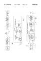
- FIG. 1is a block diagram of a system for transporting RF power to an RF transponder.
- FIG. 2is a block diagram of an RF transponder having an independent power means and a switching means for switching on the independent power means when the switching means is energized by the transported RF power or, alternatively, when a part of the tag electronics is energized by the transported RF power.
- FIG. 3is block diagram of an alternative preferred apparatus of the invention.
- FIG. 4ais the power and FIG. 4b is the frequency transmitted as a function of time in one of the preferred methods of the invention.
- FIG. 5ais the power and fig. 5b is the frequency transmitted as a function of time in one of the preferred methods of the invention.
- FIG. 6is a block diagram of an alternative preferred method of the invention.
- a method of transporting power to a remote antenna connected to electronic circuitry for the purpose of energizing the electronic circuitryis proposed.
- a preferred embodimentis to transport power to an RF Identification and Location transponder (RFID Transponder) having logic circuits, memory circuits, and antenna impedance control circuits.
- RFID TransponderRFID Transponder
- the memory circuitscan be written and read remotely. Examples of preferred RFID transponders and base stations are given in U.S. Pat. No. 4,656,463 issued on Apr. 7, 1987 by Anders et. al., which patent is hereby incorporated by reference.
- FIG. 1is a block diagram outlining the apparatus needed for implementing the method of the invention.
- a base station transmitter 10is controlled by computer means 12 to send various frequencies and amplitudes of RF energy to base station antenna 14.
- Antenna 14radiates an RF electromagnetic wave 15 which causes a current to oscillate in tag antenna 16 of the transponder (tag) 17 receiving the RF power.
- a voltage rectifying power circuit 18 connected to tag antenna 16provides power to energy store 19 while the RF energy 15 is being broadcast.
- Energy store 19can be any means known in the art for storing energy, but is typically a capacitor on a semiconductor chip. Energy store 19 supplies energy to the electronic circuitry 20.
- Electronic circuitry 20may contain communication circuitry for receiving communications sent from the base station in the form of modulations of the RF energy and/or frequency.
- Electronic circuitry 20may contain a read only memory and/or a read write memory and/or a means for changing the loading on the tag antenna in order to change the back scattering characteristics of the tag antenna for purposes of communication with the base station.
- Computer 12may also be used to receive, analyze, store, and communicate data sent by the base station transmitter 10 to the transponder. Computer 12 may also receive and communicate data sent by the tag to a receiver (not shown).
- the tagrequires both power to operate, and a minimum voltage to run the semiconductor devices in the tag electronics 20. It is important that the voltage supplied by the tag energy store 19 not drop below a threshold level during the tag communication protocol.
- the energy stored in the tag energy store 19is depleted in a characteristic time t. which depends on the capacity of the tag energy store 19, the amount of energy actually stored in the tag energy store 19, (since the tag may be in a range from the base station where the energy store is not fully charged) and the power demands of circuitry 20.
- the capacity of the tag energy storecan be made quite large, but for low cost tags, it should be in the range of the energy storage capacitance of capacitors formed by normal electronics technology used for semiconductor chips. More capacitance takes more area on the chip, and is more costly. It is necessary that the RF transmission of energy not be interrupted for a time to greater than the critical time t c .
- the RF transmission of energybe interrupted for a time t o less than 400 milliseconds. It is more preferable that the transmission be interrupted for a time t o less than 400 microseconds, even more preferable that the transmission be interrupted for a time t o less than 50 microseconds, and most preferable that the transmission be interrupted for a time t o less than 30 microseconds. (See discussion of FIG. 5 below),
- FIG. 2shows a block diagram of the apparatus for implementing a preferred method of the invention where the tag 17 is an active tag which contains an energy supply means 22 such as a battery and a switch means 24 for connecting the energy supply means 22 to the tag electronics 20 when the switch means 24 is energized by the voltage rectifying power circuit 18 and the energy store 19.
- Electronic circuitry decision means 26which is part of the tag electronics 20 may alternatively be energized by the voltage rectifying power circuit 18, and decision means 26 may decide on the basis of the power received by the energy supply means 22 to fully energize electronic circuitry 20 by connecting energy supply means 22 with the tag electronics through switch means 24.
- the frequency sent out from the base stationmust be changed over time. However, if the frequency is changed slowly from a first frequency f 1 to a second frequency f 2 , the sent out frequency passes through a number of other frequencies in between f 1 and f 2 . If the frequency is changed very rapidly, a large bandwidth of frequencies is generated, with the bandwidth center sweeping from f 1 to f 2 over time. Both of these results would result in possible interference with other users of the spectrum, which is prohibited by FCC regulations.
- a preferred methodis to turn off the transmitter or reduce the power of the transmitter while the frequency change is taking place.
- the tagrelies on the sent out power to keep critical functions, such as its "short term memory", active while the tag and the base station are in communication with each other.
- critical functions of the tagwhich would be affected by loss of power are the "clock signal” which would be lost and a "tag state” which would be changed. Loss of the "short term memory” would seriously affect communication protocols for the tag, IE. the multiple tag communication protocols referred to above. It is critical that the power be turned off for a very short time.
- a base station transmitter 10 for transporting RF power to RF transponders shown in FIG. 3enables sending out two different frequency pulses separated by a very short time, specifically less than t c .
- a single RF generator 50is used to sequentially generate two different RF frequencies f 1 and f 2 under control of the computer 12 over line 51.
- RF generator 50can switch frequencies in a time less than the time t c which is taken for the tag energy store 19 to be drained to a level where a critical tag function is impaired.
- amplifier/modulator unit 90is switched off under control of computer 12 over line 93.
- RF generators 50 (and 60) and RF amplifier/modulatorsare well known.
- one or more additional optional RF generators 60are included in the base station transmitter means 10.
- Optional RF switch 70is controlled by computer 12 over line 71 to switch either RF generator 50 or optional RF generator 60 to the rest of the base station transmitter 10.
- RF generator 50For a time t p RF generator 50 is connected via lines 81 and 52 through switch 70 to an optional signal splitter 80 which divides the RF signal coming from the switch 70. A small part of the RF energy from RF generator 50 is tapped off in splitter 80 to be sent to an RF receiver (not shown) via line 82. (The RF receiver uses the frequency as a comparison to detect the backscattered radiation from the tags.) Most of the RF energy from RF generator 50 is sent to amplifier modulator module 90 via line 91. Amplifier/Modulator module 90 is controlled via line 93 by computer 12, and sends amplified and optionally modulated RF energy over line 94 to antenna 14.
- the RF power and the RF frequency as a function of timeare shown in FIG. 4a and FIG. 4b respectively.
- the RF poweris on for a pulse time t p of 300 to 400 milliseconds, for an RF frequency approximately 2.4 Ghz. Then, the power is reduced to a very small amount, which is preferably zero.
- a power that is lower than an FCC power limit P FCCdefined as the maximum power that can be sent out of frequency channel being used, is sent out from antenna 14 during a time t FCC .
- the computerinstructs switch 70 to switch from frequency generator 50 to frequency generator 60 during the time t FCC .
- Well known RF switchessuch as switch 70 can easily switch from one source to the other in less than a microsecond.
- frequency generator 60has had ample time to change frequencies to frequency f 2 from its previous frequency.
- a frequencyis chosen from a frequency list 13 stored in the computer memory or other memory location to be the next frequency to be transmitted, and instructs RF generator 50 to set itself to the next frequency required after frequency f2 so that the sent out frequency can again be changed during the next power off time.
- the computerthen instructs modulator 90 to amplify once again and send the next pulse of RF power to antenna 14.
- the RF generator 50has settled to the new frequency and the switch 70 switches back to generator 50 during the time the amplifier 90 is turned off again.
- the transmitted RF power and frequency during a changeoverare shown in FIG. 5a and 5brespectively.
- the rise time t r and fall time t f of the power during the switchingare very important.
- side bands of frequencies f 1 and f 2 respectivelywill be generated and sent to the antenna 14.
- the allowed frequency broadeningdepends on the frequency bands used. If the frequency broadening is too great, the sidebands may cause interference, which is not allowed.
- the frequency broadeningbecomes greater as t 1 and t f are reduced. There is thus a limit below which t 1 and t f may not be reduced.
- the off time t o during which the RF power sent out is reduced below power P minwhere P min is the power which can sustain the energy in the tag energy store 19 above the level needed by the tag electronics 20, must be greater than t FCC plus the time taken to reduce power from P min to P FCC plus the time taken to raise the power again from P FCC to P min .
- the off time t oin the 2.4 Ghz band, must be longer than approximately 700 nanoseconds to allow for both the rise and fall times shown in FIG. 5a. More preferably, the off time is longer than 10 microseconds.
- off time t omust be shorter than a first limit time because the tag will lose memory or other tag function, and longer than a second limit time, so that the frequency sent may change without introducing interfering levels of RF power outside the allowed channels.
- the frequency shifts of the transmittercan be random or can be programmed to a particular pattern such as a ramp or stair step pattern which used sufficient frequencies in the bandwidth that the limits on average power in a particular frequency would not exceed regulations.
- a pseudo random patternis the most preferred pattern.
- a preferred method of the inventionis given by the flow chart 600 in FIG. 6, and comprises the steps of:
Landscapes
- Engineering & Computer Science (AREA)
- Physics & Mathematics (AREA)
- General Physics & Mathematics (AREA)
- Theoretical Computer Science (AREA)
- Computer Hardware Design (AREA)
- Microelectronics & Electronic Packaging (AREA)
- Artificial Intelligence (AREA)
- Computer Vision & Pattern Recognition (AREA)
- Near-Field Transmission Systems (AREA)
- Radar Systems Or Details Thereof (AREA)
Abstract
Description
Claims (30)
Priority Applications (6)
| Application Number | Priority Date | Filing Date | Title |
|---|---|---|---|
| US08/626,820US5850181A (en) | 1996-04-03 | 1996-04-03 | Method of transporting radio frequency power to energize radio frequency identification transponders |
| US09/426,235US6400274B1 (en) | 1995-08-31 | 1999-10-25 | High-performance mobile power antennas |
| US09/658,953US6429775B1 (en) | 1996-04-03 | 2000-09-11 | Apparatus for transporting radio frequency power to energize radio frequency identification transponders |
| US10/770,341US7215248B2 (en) | 1995-08-31 | 2004-02-02 | Diode receiver for radio frequency transponder |
| US11/694,229US7511621B1 (en) | 1995-08-31 | 2007-03-30 | High-performance mobile power antennas |
| US12/412,627US8049625B1 (en) | 1995-08-31 | 2009-03-27 | High-performance mobile power antennas |
Applications Claiming Priority (1)
| Application Number | Priority Date | Filing Date | Title |
|---|---|---|---|
| US08/626,820US5850181A (en) | 1996-04-03 | 1996-04-03 | Method of transporting radio frequency power to energize radio frequency identification transponders |
Related Parent Applications (1)
| Application Number | Title | Priority Date | Filing Date |
|---|---|---|---|
| US26305799AContinuation-In-Part | 1995-08-31 | 1999-03-06 |
Related Child Applications (2)
| Application Number | Title | Priority Date | Filing Date |
|---|---|---|---|
| US11403798AContinuation | 1995-08-31 | 1998-07-10 | |
| US21158498AContinuation | 1995-08-31 | 1998-12-14 |
Publications (1)
| Publication Number | Publication Date |
|---|---|
| US5850181Atrue US5850181A (en) | 1998-12-15 |
Family
ID=24512000
Family Applications (1)
| Application Number | Title | Priority Date | Filing Date |
|---|---|---|---|
| US08/626,820Expired - LifetimeUS5850181A (en) | 1995-08-31 | 1996-04-03 | Method of transporting radio frequency power to energize radio frequency identification transponders |
Country Status (1)
| Country | Link |
|---|---|
| US (1) | US5850181A (en) |
Cited By (79)
| Publication number | Priority date | Publication date | Assignee | Title |
|---|---|---|---|---|
| WO1999045494A1 (en)* | 1998-03-04 | 1999-09-10 | Trolley Scan (Proprietary) Limited | Multi-dimensional electronic identification of articles |
| US6054925A (en)* | 1997-08-27 | 2000-04-25 | Data Investments Limited | High impedance transponder with improved backscatter modulator for electronic identification system |
| US6100804A (en)* | 1998-10-29 | 2000-08-08 | Intecmec Ip Corp. | Radio frequency identification system |
| US6104291A (en)* | 1998-01-09 | 2000-08-15 | Intermec Ip Corp. | Method and apparatus for testing RFID tags |
| US6121878A (en)* | 1998-05-01 | 2000-09-19 | Intermec Ip Corp. | System for controlling assets |
| US6177872B1 (en) | 1998-03-13 | 2001-01-23 | Intermec Ip Corp. | Distributed impedance matching circuit for high reflection coefficient load |
| US6201474B1 (en) | 1998-10-21 | 2001-03-13 | Intermec Ip Corp. | Magnetic tape storage media having RFID transponders |
| US6236223B1 (en) | 1998-11-09 | 2001-05-22 | Intermec Ip Corp. | Method and apparatus for wireless radio frequency testing of RFID integrated circuits |
| US6249227B1 (en) | 1998-01-05 | 2001-06-19 | Intermec Ip Corp. | RFID integrated in electronic assets |
| US6275143B1 (en)* | 1997-05-09 | 2001-08-14 | Anatoli Stobbe | Security device having wireless energy transmission |
| US6281794B1 (en) | 1998-01-02 | 2001-08-28 | Intermec Ip Corp. | Radio frequency transponder with improved read distance |
| US6326889B1 (en) | 1999-07-29 | 2001-12-04 | Micron Technology, Inc. | Radio frequency identification device and methods of determining a communication range of an interrogator of a wireless identification system |
| US6404325B1 (en) | 1998-01-08 | 2002-06-11 | Intermec Ip Corp. | Method and system for storage and recovery of vital information on radio frequency transponders |
| US6429775B1 (en)* | 1996-04-03 | 2002-08-06 | Intermec Ip Corp. | Apparatus for transporting radio frequency power to energize radio frequency identification transponders |
| US6441740B1 (en) | 1998-02-27 | 2002-08-27 | Intermec Ip Corp. | Radio frequency identification transponder having a reflector |
| US20020135481A1 (en)* | 2001-03-06 | 2002-09-26 | Conwell Kevin Girard | Tamper evident smart label with RF transponder |
| US6459376B2 (en)* | 1999-07-29 | 2002-10-01 | Micron Technology, Inc. | Radio frequency identification devices, remote communication devices, wireless communication systems, and methods of indicating operation |
| US6462647B1 (en)* | 1998-11-03 | 2002-10-08 | Em Microelectronic-Marin Sa | Rechargeable active transponder |
| US20020149483A1 (en)* | 2001-02-12 | 2002-10-17 | Matrics, Inc. | Method, System, and apparatus for communicating with a RFID tag population |
| US20020154029A1 (en)* | 1999-02-26 | 2002-10-24 | Sri International | Sensor devices for structural health monitoring |
| US20020176366A1 (en)* | 2001-03-13 | 2002-11-28 | Microsoft Corporation | System and method for achieving zero-configuration wireless computing and computing device incorporating same |
| US20030017804A1 (en)* | 2001-07-23 | 2003-01-23 | Heinrich Harley Kent | RFID tag having combined battery and passive power source |
| US20030081845A1 (en)* | 2001-11-01 | 2003-05-01 | Debargha Mukherjee | Single-pass guaranteed-fit data compression using rate feedback |
| US20030112128A1 (en)* | 2000-02-28 | 2003-06-19 | Littlechild Stuart Colin | Radio frequency identification transponder |
| US20030137400A1 (en)* | 2002-01-23 | 2003-07-24 | Intermec Ip Corp. | Passive RFID tag that retains state after temporary loss of power |
| US6617963B1 (en) | 1999-02-26 | 2003-09-09 | Sri International | Event-recording devices with identification codes |
| US20030197597A1 (en)* | 2002-04-17 | 2003-10-23 | Microsoft Corporation | Reducing power consumption in a networked battery-operated device using sensors |
| US20030198196A1 (en)* | 2002-04-17 | 2003-10-23 | Microsoft Corporation | Reducing idle power consumption in a networked battery operated device |
| US6639509B1 (en) | 1998-03-16 | 2003-10-28 | Intermec Ip Corp. | System and method for communicating with an RFID transponder with reduced noise and interference |
| US20030203740A1 (en)* | 2002-04-17 | 2003-10-30 | Microsoft Corporation | Power efficient channel scheduling in a wireless network |
| US20030212787A1 (en)* | 2002-05-13 | 2003-11-13 | Microsoft Corporation | Adaptive allocation of last-hop bandwidth based on monitoring of end-to-end throughput |
| US6664770B1 (en)* | 1999-12-05 | 2003-12-16 | Iq- Mobil Gmbh | Wireless power transmission system with increased output voltage |
| US20040068368A1 (en)* | 2000-11-15 | 2004-04-08 | International Business Machines Corporation | Apparatus, system, and method for determining a user position and progress along a path |
| US6745008B1 (en) | 2000-06-06 | 2004-06-01 | Battelle Memorial Institute K1-53 | Multi-frequency communication system and method |
| US6779246B2 (en) | 2001-04-23 | 2004-08-24 | Appleton Papers Inc. | Method and system for forming RF reflective pathways |
| US20040204071A1 (en)* | 2002-05-01 | 2004-10-14 | Microsoft Corporation | Method for wireless capability discovery and protocol negotiation, and wireless device including same |
| US6806808B1 (en) | 1999-02-26 | 2004-10-19 | Sri International | Wireless event-recording device with identification codes |
| US20050083201A1 (en)* | 1999-07-29 | 2005-04-21 | Trosper Scott T. | Radio frequency identification devices, remote communication devices, identification systems, communication methods, and identification methods |
| US6892441B2 (en) | 2001-04-23 | 2005-05-17 | Appleton Papers Inc. | Method for forming electrically conductive pathways |
| US6914528B2 (en)* | 2002-10-02 | 2005-07-05 | Battelle Memorial Institute | Wireless communication systems, radio frequency identification devices, methods of enhancing a communications range of a radio frequency identification device, and wireless communication methods |
| US20050179521A1 (en)* | 2004-02-12 | 2005-08-18 | Intermec Ip Corp. | Frequency hopping method for RFID tag |
| US20050242196A1 (en)* | 2001-05-31 | 2005-11-03 | Alien Technology Corp. | Integrated circuits with persistent data storage |
| US20050254183A1 (en)* | 2004-05-12 | 2005-11-17 | Makota Ishida | Power generation circuit using electromagnetic wave |
| US6970089B2 (en) | 2002-07-03 | 2005-11-29 | Battelle Memorial Institute K1-53 | Full-spectrum passive communication system and method |
| US6972682B2 (en) | 2002-01-18 | 2005-12-06 | Georgia Tech Research Corporation | Monitoring and tracking of assets by utilizing wireless communications |
| US20060176154A1 (en)* | 2000-02-28 | 2006-08-10 | Littlechild Stuart Colin | Radio frequency identification transponder |
| US7106196B2 (en) | 2001-07-12 | 2006-09-12 | Intermec Ip Corp | Method and apparatus for configuring the read-range of an RFID label or tag |
| US20060226841A1 (en)* | 2005-04-06 | 2006-10-12 | Boskamp Eddy B | Wireless rf coil power supply |
| US20060261938A1 (en)* | 2005-05-19 | 2006-11-23 | Lai Kin Y A | Radio Frequency Identification (RFID) system |
| US20070001848A1 (en)* | 2005-06-30 | 2007-01-04 | Symbol Technologies, Inc. | Systems and methods for reducing interference by modulating a reader transmittal signal within the transmission channel |
| US20070096881A1 (en)* | 2005-10-28 | 2007-05-03 | Vijay Pillai | System and method of enhancing range in a radio frequency identification system |
| US7286798B1 (en)* | 2002-10-15 | 2007-10-23 | Ncr Corporation | Electronic shelf label |
| US20070287508A1 (en)* | 2006-06-08 | 2007-12-13 | Flextronics Ap, Llc | Contactless energy transmission converter |
| US20080111675A1 (en)* | 2006-11-10 | 2008-05-15 | Micron Technology, Inc. | Tracking systems, passive RFIDs, methods of locating and identifying RFIDs, and methods of tracking items |
| US7377445B1 (en)* | 2001-05-31 | 2008-05-27 | Alien Technology Corporation | Integrated circuits with persistent data storage |
| US20080136635A1 (en)* | 2006-12-08 | 2008-06-12 | Symbol Technologies, Inc. | Low power rfid reader that gives visibility to passive tags as active tags using low power 802.11 |
| US20080186178A1 (en)* | 2007-02-07 | 2008-08-07 | Micron Technology, Inc. | RFIDS, interrogators, indication systems, methods of determining a bi-directional communication range of an interrogator, methods of activating an observable indicator, and methods of indicating bi-directional functionality of a radio connection |
| US20080190480A1 (en)* | 2007-02-14 | 2008-08-14 | Flextronics Ap, Llc | Leadframe based photo voltaic electronic assembly |
| US20080200125A1 (en)* | 2005-09-02 | 2008-08-21 | Koninklijke Philips Electronics, N.V. | Radio Broadcasting Device |
| US7427912B1 (en) | 1998-01-08 | 2008-09-23 | Intermec Ip Corp. | Method and system for storage and recovery of vital information on radio frequency transponders |
| US7511621B1 (en)* | 1995-08-31 | 2009-03-31 | Intermec Ip Corp. | High-performance mobile power antennas |
| US7564810B2 (en) | 2002-05-08 | 2009-07-21 | Microsoft Corporation | Method and system for managing power consumption of a network interface module in a wireless computing device |
| US7633378B2 (en) | 1998-06-02 | 2009-12-15 | Rf Code, Inc. | Object identification system with adaptive transceivers and methods of operation |
| USD626949S1 (en) | 2008-02-20 | 2010-11-09 | Vocollect Healthcare Systems, Inc. | Body-worn mobile device |
| US20110140852A1 (en)* | 2009-06-19 | 2011-06-16 | Stmicroelectronics (Rousset) Sas | Power management in an electromagnetic transponder |
| USD643013S1 (en) | 2010-08-20 | 2011-08-09 | Vocollect Healthcare Systems, Inc. | Body-worn mobile device |
| USD643400S1 (en) | 2010-08-19 | 2011-08-16 | Vocollect Healthcare Systems, Inc. | Body-worn mobile device |
| US8049625B1 (en)* | 1995-08-31 | 2011-11-01 | Intermac Technologies Corporation | High-performance mobile power antennas |
| EP1854219A4 (en)* | 2005-02-24 | 2011-12-21 | Powercast Corp | Method, apparatus and system for power transmitssion |
| US8128422B2 (en) | 2002-06-27 | 2012-03-06 | Vocollect, Inc. | Voice-directed portable terminals for wireless communication systems |
| US8386261B2 (en) | 2008-11-14 | 2013-02-26 | Vocollect Healthcare Systems, Inc. | Training/coaching system for a voice-enabled work environment |
| US8659397B2 (en) | 2010-07-22 | 2014-02-25 | Vocollect, Inc. | Method and system for correctly identifying specific RFID tags |
| US8665074B1 (en)* | 2006-10-24 | 2014-03-04 | Impinj, Inc. | RFID tag chips and tags with alternative behaviors and methods |
| US9152909B2 (en) | 2008-07-21 | 2015-10-06 | Sato Vicinity Pty Ltd | Device having data storage |
| US9361564B2 (en) | 2013-12-02 | 2016-06-07 | Qualcomm Technologies International, Ltd. | Protection of an NFC or RFID radio in the presence of strong electromagnetic fields |
| US20200050804A1 (en)* | 2004-07-09 | 2020-02-13 | Amtech Systems, LLC | Multi-protocol rfid system |
| US10628723B2 (en) | 2018-07-10 | 2020-04-21 | Datamax-O'neil Corporation | Methods, systems, and apparatuses for encoding a radio frequency identification (RFID) inlay |
| EP3702969A1 (en) | 2019-02-26 | 2020-09-02 | Kornelis Wiegers | Integrated labeling of medical supplies |
| US20210027608A1 (en)* | 2019-04-11 | 2021-01-28 | Nexite Ltd. | Wireless dual-mode identification tag |
Citations (5)
| Publication number | Priority date | Publication date | Assignee | Title |
|---|---|---|---|---|
| US4566009A (en)* | 1979-10-16 | 1986-01-21 | Siemens Aktiengesellschaft | Identification, friend or foe IFF installation |
| US5109217A (en)* | 1990-08-09 | 1992-04-28 | Sensormatic Electronics Corporation | Method and apparatus for enhancing detection of electronic article surveillance tags in close proximity to electrically conductive objects |
| US5349332A (en)* | 1992-10-13 | 1994-09-20 | Sensormatic Electronics Corportion | EAS system with requency hopping |
| US5438332A (en)* | 1992-02-28 | 1995-08-01 | Thomson-Csf | Method of hardening transmissions, in particular between a control station and a transponder, and a device implementing the method |
| US5495229A (en)* | 1994-09-28 | 1996-02-27 | Sensormatic Electronics Corporation | Pulsed electronic article surveillance device employing expert system techniques for dynamic optimization |
- 1996
- 1996-04-03USUS08/626,820patent/US5850181A/ennot_activeExpired - Lifetime
Patent Citations (5)
| Publication number | Priority date | Publication date | Assignee | Title |
|---|---|---|---|---|
| US4566009A (en)* | 1979-10-16 | 1986-01-21 | Siemens Aktiengesellschaft | Identification, friend or foe IFF installation |
| US5109217A (en)* | 1990-08-09 | 1992-04-28 | Sensormatic Electronics Corporation | Method and apparatus for enhancing detection of electronic article surveillance tags in close proximity to electrically conductive objects |
| US5438332A (en)* | 1992-02-28 | 1995-08-01 | Thomson-Csf | Method of hardening transmissions, in particular between a control station and a transponder, and a device implementing the method |
| US5349332A (en)* | 1992-10-13 | 1994-09-20 | Sensormatic Electronics Corportion | EAS system with requency hopping |
| US5495229A (en)* | 1994-09-28 | 1996-02-27 | Sensormatic Electronics Corporation | Pulsed electronic article surveillance device employing expert system techniques for dynamic optimization |
Cited By (165)
| Publication number | Priority date | Publication date | Assignee | Title |
|---|---|---|---|---|
| US7511621B1 (en)* | 1995-08-31 | 2009-03-31 | Intermec Ip Corp. | High-performance mobile power antennas |
| US8049625B1 (en)* | 1995-08-31 | 2011-11-01 | Intermac Technologies Corporation | High-performance mobile power antennas |
| US6429775B1 (en)* | 1996-04-03 | 2002-08-06 | Intermec Ip Corp. | Apparatus for transporting radio frequency power to energize radio frequency identification transponders |
| US6275143B1 (en)* | 1997-05-09 | 2001-08-14 | Anatoli Stobbe | Security device having wireless energy transmission |
| US6054925A (en)* | 1997-08-27 | 2000-04-25 | Data Investments Limited | High impedance transponder with improved backscatter modulator for electronic identification system |
| US6281794B1 (en) | 1998-01-02 | 2001-08-28 | Intermec Ip Corp. | Radio frequency transponder with improved read distance |
| US6249227B1 (en) | 1998-01-05 | 2001-06-19 | Intermec Ip Corp. | RFID integrated in electronic assets |
| US7427912B1 (en) | 1998-01-08 | 2008-09-23 | Intermec Ip Corp. | Method and system for storage and recovery of vital information on radio frequency transponders |
| US6404325B1 (en) | 1998-01-08 | 2002-06-11 | Intermec Ip Corp. | Method and system for storage and recovery of vital information on radio frequency transponders |
| US6104291A (en)* | 1998-01-09 | 2000-08-15 | Intermec Ip Corp. | Method and apparatus for testing RFID tags |
| US6441740B1 (en) | 1998-02-27 | 2002-08-27 | Intermec Ip Corp. | Radio frequency identification transponder having a reflector |
| US6909366B1 (en) | 1998-03-04 | 2005-06-21 | Trolley Scan (Proprietary) Limited | Multi-dimensional electronic identification of articles |
| WO1999045494A1 (en)* | 1998-03-04 | 1999-09-10 | Trolley Scan (Proprietary) Limited | Multi-dimensional electronic identification of articles |
| AU768601B2 (en)* | 1998-03-04 | 2003-12-18 | Trolley Scan (Proprietary) Limited | Multi-dimensional electronic identification of articles |
| US6177872B1 (en) | 1998-03-13 | 2001-01-23 | Intermec Ip Corp. | Distributed impedance matching circuit for high reflection coefficient load |
| US6639509B1 (en) | 1998-03-16 | 2003-10-28 | Intermec Ip Corp. | System and method for communicating with an RFID transponder with reduced noise and interference |
| US6121878A (en)* | 1998-05-01 | 2000-09-19 | Intermec Ip Corp. | System for controlling assets |
| US7633378B2 (en) | 1998-06-02 | 2009-12-15 | Rf Code, Inc. | Object identification system with adaptive transceivers and methods of operation |
| US6201474B1 (en) | 1998-10-21 | 2001-03-13 | Intermec Ip Corp. | Magnetic tape storage media having RFID transponders |
| US6100804A (en)* | 1998-10-29 | 2000-08-08 | Intecmec Ip Corp. | Radio frequency identification system |
| US6462647B1 (en)* | 1998-11-03 | 2002-10-08 | Em Microelectronic-Marin Sa | Rechargeable active transponder |
| US6236223B1 (en) | 1998-11-09 | 2001-05-22 | Intermec Ip Corp. | Method and apparatus for wireless radio frequency testing of RFID integrated circuits |
| US7034660B2 (en) | 1999-02-26 | 2006-04-25 | Sri International | Sensor devices for structural health monitoring |
| US20020154029A1 (en)* | 1999-02-26 | 2002-10-24 | Sri International | Sensor devices for structural health monitoring |
| US7986218B2 (en) | 1999-02-26 | 2011-07-26 | Yasumi Capital, Llc | Sensor devices for structural health monitoring |
| US20060170535A1 (en)* | 1999-02-26 | 2006-08-03 | Sri International | Sensor devices for structural health monitoring |
| US6806808B1 (en) | 1999-02-26 | 2004-10-19 | Sri International | Wireless event-recording device with identification codes |
| US6617963B1 (en) | 1999-02-26 | 2003-09-09 | Sri International | Event-recording devices with identification codes |
| US6326889B1 (en) | 1999-07-29 | 2001-12-04 | Micron Technology, Inc. | Radio frequency identification device and methods of determining a communication range of an interrogator of a wireless identification system |
| US20070035395A1 (en)* | 1999-07-29 | 2007-02-15 | Trosper Scott T | Wireless communication devices, radio frequency identification devices, radio frequency identification device communication systems, wireless communication methods, and radio frequency identification device communication methods |
| US7071824B2 (en) | 1999-07-29 | 2006-07-04 | Micron Technology, Inc. | Radio frequency identification devices, remote communication devices, identification systems, communication methods, and identification methods |
| US6545605B2 (en) | 1999-07-29 | 2003-04-08 | Micron Technology, Inc. | Methods of determining a communications range of an interrogator of a wireless identification system and methods of verifying operation of a wireless identification system |
| US8487766B2 (en) | 1999-07-29 | 2013-07-16 | Round Rock Research, LLP | Radio frequency identification devices, remote communication devices, identification systems, communication methods, and identification methods |
| US7123148B2 (en) | 1999-07-29 | 2006-10-17 | Micron Technology, Inc. | Wireless communication devices, radio frequency identification devices, radio frequency identification device communication systems, wireless communication methods, and radio frequency identification device communication methods |
| US8253565B2 (en) | 1999-07-29 | 2012-08-28 | Round Rock Research, Llc | Radio frequency identification devices, remote communication devices, identification systems, communication methods, and identification methods |
| US7518515B2 (en) | 1999-07-29 | 2009-04-14 | Keystone Technology Solutions, Llc | Method and system for RFID communication |
| US20100013637A1 (en)* | 1999-07-29 | 2010-01-21 | Keystone Technology Solutions, Llc | Radio Frequency Identification Devices, Remote Communication Devices, Identification Systems, Communication Methods, and Identification Methods |
| US7737851B2 (en) | 1999-07-29 | 2010-06-15 | Round Rock Research, Llc | Radio frequency identification devices, remote communication devices, identification systems, communication methods, and identification methods |
| US6466130B2 (en) | 1999-07-29 | 2002-10-15 | Micron Technology, Inc. | Wireless communication devices, wireless communication systems, communication methods, methods of forming radio frequency identification devices, methods of testing wireless communication operations, radio frequency identification devices, and methods of forming radio frequency identification devices |
| US8004407B2 (en) | 1999-07-29 | 2011-08-23 | Round Rock Research, Llc | Radio frequency identification devices, remote communication devices, identification systems, communication methods, and identification methods |
| US6459376B2 (en)* | 1999-07-29 | 2002-10-01 | Micron Technology, Inc. | Radio frequency identification devices, remote communication devices, wireless communication systems, and methods of indicating operation |
| US6452496B1 (en) | 1999-07-29 | 2002-09-17 | Micron Technology, Inc. | Radio frequency identification devices and a method of determining a communication range |
| US20050083201A1 (en)* | 1999-07-29 | 2005-04-21 | Trosper Scott T. | Radio frequency identification devices, remote communication devices, identification systems, communication methods, and identification methods |
| US6664770B1 (en)* | 1999-12-05 | 2003-12-16 | Iq- Mobil Gmbh | Wireless power transmission system with increased output voltage |
| US8319609B2 (en) | 2000-02-28 | 2012-11-27 | Magellan Technology Pty Limited | Radio frequency identification transponder |
| US20080197976A1 (en)* | 2000-02-28 | 2008-08-21 | Littlechild Stuart Colin | Radio frequency identification transponder |
| US20070139160A1 (en)* | 2000-02-28 | 2007-06-21 | Littlechild Stuart Colin | Radio frequency identification transponder |
| US8159332B2 (en) | 2000-02-28 | 2012-04-17 | Magellan Technology Pty Limited | Radio frequency identification transponder |
| US7248145B2 (en) | 2000-02-28 | 2007-07-24 | Magellan Technology Oty Limited | Radio frequency identification transponder |
| US7259654B2 (en) | 2000-02-28 | 2007-08-21 | Magellan Technology Pty Limited | Radio frequency identification transponder |
| US20060176154A1 (en)* | 2000-02-28 | 2006-08-10 | Littlechild Stuart Colin | Radio frequency identification transponder |
| US8325016B2 (en) | 2000-02-28 | 2012-12-04 | Magellan Technology Pty Limited | Radio frequency identification transponder |
| US20030112128A1 (en)* | 2000-02-28 | 2003-06-19 | Littlechild Stuart Colin | Radio frequency identification transponder |
| US6745008B1 (en) | 2000-06-06 | 2004-06-01 | Battelle Memorial Institute K1-53 | Multi-frequency communication system and method |
| US20040068368A1 (en)* | 2000-11-15 | 2004-04-08 | International Business Machines Corporation | Apparatus, system, and method for determining a user position and progress along a path |
| US20060061473A1 (en)* | 2001-02-12 | 2006-03-23 | Symbol Technologies, Inc. | Method, system, and apparatus for communicating with a RFID tag population |
| US7057511B2 (en)* | 2001-02-12 | 2006-06-06 | Symbol Technologies, Inc. | Method, system, and apparatus for communicating with a RFID tag population |
| US7199716B2 (en) | 2001-02-12 | 2007-04-03 | Symbol Technologies, Inc. | Method, system, and apparatus for communicating with a RFID tag population |
| US20020149483A1 (en)* | 2001-02-12 | 2002-10-17 | Matrics, Inc. | Method, System, and apparatus for communicating with a RFID tag population |
| US7965189B2 (en) | 2001-02-12 | 2011-06-21 | Symbol Technologies, Inc. | Radio frequency identification architecture |
| US7928843B2 (en) | 2001-02-12 | 2011-04-19 | Symbol Technologies, Inc. | Method, system, and apparatus for communications in a RFID system |
| US7414517B2 (en) | 2001-02-28 | 2008-08-19 | Magellan Technology Pty Limited | Radio frequency identification transponder |
| US7095324B2 (en) | 2001-03-06 | 2006-08-22 | Intermec Ip Corp | Tamper evident smart label with RF transponder |
| US20020135481A1 (en)* | 2001-03-06 | 2002-09-26 | Conwell Kevin Girard | Tamper evident smart label with RF transponder |
| US20060239209A1 (en)* | 2001-03-13 | 2006-10-26 | Microsoft Corporation | System and method for achieving zero-configuration wireless computing and computing device incorporating same |
| US7512081B2 (en) | 2001-03-13 | 2009-03-31 | Microsoft Corporation | System and method for achieving zero-configuration wireless and wired computing and computing device incorporating same |
| US20020176366A1 (en)* | 2001-03-13 | 2002-11-28 | Microsoft Corporation | System and method for achieving zero-configuration wireless computing and computing device incorporating same |
| US7120129B2 (en) | 2001-03-13 | 2006-10-10 | Microsoft Corporation | System and method for achieving zero-configuration wireless computing and computing device incorporating same |
| US6779246B2 (en) | 2001-04-23 | 2004-08-24 | Appleton Papers Inc. | Method and system for forming RF reflective pathways |
| US20050151700A1 (en)* | 2001-04-23 | 2005-07-14 | Appleton Papers Inc. | Method and system for forming electrically conductive pathways |
| US6892441B2 (en) | 2001-04-23 | 2005-05-17 | Appleton Papers Inc. | Method for forming electrically conductive pathways |
| US20050242196A1 (en)* | 2001-05-31 | 2005-11-03 | Alien Technology Corp. | Integrated circuits with persistent data storage |
| US7737825B1 (en) | 2001-05-31 | 2010-06-15 | Alien Technology Corporation | Integrated circuits with persistent data storage |
| US8056818B2 (en) | 2001-05-31 | 2011-11-15 | Alien Technology Corporation | Integrated circuits with persistent data storage |
| US7364084B2 (en) | 2001-05-31 | 2008-04-29 | Alien Technology Corporation | Integrated circuits with persistent data storage |
| US7377445B1 (en)* | 2001-05-31 | 2008-05-27 | Alien Technology Corporation | Integrated circuits with persistent data storage |
| US9406012B2 (en) | 2001-05-31 | 2016-08-02 | Ruizhang Technology Limited Company | Integrated circuits with persistent data storage |
| US8936201B2 (en) | 2001-05-31 | 2015-01-20 | Alien Technology, Llc | Integrated circuits with persistent data storage |
| US8464957B2 (en) | 2001-05-31 | 2013-06-18 | Alien Technology Corporation | Integrated circuits with persistent data storage |
| US7106196B2 (en) | 2001-07-12 | 2006-09-12 | Intermec Ip Corp | Method and apparatus for configuring the read-range of an RFID label or tag |
| US6944424B2 (en)* | 2001-07-23 | 2005-09-13 | Intermec Ip Corp. | RFID tag having combined battery and passive power source |
| US20030017804A1 (en)* | 2001-07-23 | 2003-01-23 | Heinrich Harley Kent | RFID tag having combined battery and passive power source |
| US20030081845A1 (en)* | 2001-11-01 | 2003-05-01 | Debargha Mukherjee | Single-pass guaranteed-fit data compression using rate feedback |
| US6972682B2 (en) | 2002-01-18 | 2005-12-06 | Georgia Tech Research Corporation | Monitoring and tracking of assets by utilizing wireless communications |
| US20030137400A1 (en)* | 2002-01-23 | 2003-07-24 | Intermec Ip Corp. | Passive RFID tag that retains state after temporary loss of power |
| US6812841B2 (en)* | 2002-01-23 | 2004-11-02 | Intermec Ip Corp. | Passive RFID tag that retains state after temporary loss of power |
| US7203463B2 (en) | 2002-04-17 | 2007-04-10 | Microsoft Corporation | Power efficient channel scheduling in a wireless network |
| US20050136922A1 (en)* | 2002-04-17 | 2005-06-23 | Microsoft Corporation | Power efficient channel scheduling in a wireless network |
| US7230933B2 (en) | 2002-04-17 | 2007-06-12 | Microsoft Corporation | Reducing idle power consumption in a networked battery operated device |
| US20050197119A1 (en)* | 2002-04-17 | 2005-09-08 | Microsoft Corporation | Power efficient channel scheduling in a wireless network |
| US20050136994A1 (en)* | 2002-04-17 | 2005-06-23 | Microsoft Corporation | Reducing power consumption in a networked battery-operated device using sensors |
| US7016705B2 (en) | 2002-04-17 | 2006-03-21 | Microsoft Corporation | Reducing power consumption in a networked battery-operated device using sensors |
| US7539508B2 (en) | 2002-04-17 | 2009-05-26 | Microsoft Corporation | Reducing idle power consumption in a networked battery operated device |
| US20060142035A1 (en)* | 2002-04-17 | 2006-06-29 | Microsoft Corporation | Power efficient channel scheduling in a wireless network |
| US20060160559A1 (en)* | 2002-04-17 | 2006-07-20 | Microsoft Corporation | Reducing idle power consumption in a networked battery operated device |
| US7110783B2 (en) | 2002-04-17 | 2006-09-19 | Microsoft Corporation | Power efficient channel scheduling in a wireless network |
| US7245936B2 (en) | 2002-04-17 | 2007-07-17 | Microsoft Corporation | Power efficient channel scheduling in a wireless network |
| US20030197597A1 (en)* | 2002-04-17 | 2003-10-23 | Microsoft Corporation | Reducing power consumption in a networked battery-operated device using sensors |
| US7209740B2 (en) | 2002-04-17 | 2007-04-24 | Microsoft Corporation | Power efficient channel scheduling in a wireless network |
| US20030198196A1 (en)* | 2002-04-17 | 2003-10-23 | Microsoft Corporation | Reducing idle power consumption in a networked battery operated device |
| US20030203740A1 (en)* | 2002-04-17 | 2003-10-30 | Microsoft Corporation | Power efficient channel scheduling in a wireless network |
| US7142855B2 (en) | 2002-04-17 | 2006-11-28 | Microsoft Corporation | Power efficient channel scheduling in a wireless network |
| US20050101320A1 (en)* | 2002-04-17 | 2005-05-12 | Microsoft Corporation | Power efficient channel scheduling in a wireless network |
| US20050096073A1 (en)* | 2002-04-17 | 2005-05-05 | Microsoft Corporation | Power efficient channel scheduling in a wireless network |
| US6957086B2 (en) | 2002-05-01 | 2005-10-18 | Microsoft Corporation | Method for wireless capability discovery and protocol negotiation, and wireless device including same |
| US20060116148A1 (en)* | 2002-05-01 | 2006-06-01 | Microsoft Corporation | Method for wireless capability discovery and protocol negotiation, and wireless device including same |
| US20040204071A1 (en)* | 2002-05-01 | 2004-10-14 | Microsoft Corporation | Method for wireless capability discovery and protocol negotiation, and wireless device including same |
| US7519393B2 (en) | 2002-05-01 | 2009-04-14 | Microsoft Corporation | Method for wireless capability discovery and protocol negotiation, and wireless device including same |
| US7564810B2 (en) | 2002-05-08 | 2009-07-21 | Microsoft Corporation | Method and system for managing power consumption of a network interface module in a wireless computing device |
| US20030212787A1 (en)* | 2002-05-13 | 2003-11-13 | Microsoft Corporation | Adaptive allocation of last-hop bandwidth based on monitoring of end-to-end throughput |
| US7363375B2 (en) | 2002-05-13 | 2008-04-22 | Microsoft Corporation | Adaptive allocation of last-hop bandwidth based on monitoring of end-to-end throughput |
| US20060020700A1 (en)* | 2002-05-13 | 2006-01-26 | Microsoft Corporation | Adaptive allocation of last-hop bandwidth based on monitoring of end-to-end throughput |
| US7330893B2 (en) | 2002-05-13 | 2008-02-12 | Microsoft Corporation | Adaptive allocation of last-hop bandwidth based on monitoring of end-to-end throughput |
| US8128422B2 (en) | 2002-06-27 | 2012-03-06 | Vocollect, Inc. | Voice-directed portable terminals for wireless communication systems |
| US6970089B2 (en) | 2002-07-03 | 2005-11-29 | Battelle Memorial Institute K1-53 | Full-spectrum passive communication system and method |
| US6914528B2 (en)* | 2002-10-02 | 2005-07-05 | Battelle Memorial Institute | Wireless communication systems, radio frequency identification devices, methods of enhancing a communications range of a radio frequency identification device, and wireless communication methods |
| US7286798B1 (en)* | 2002-10-15 | 2007-10-23 | Ncr Corporation | Electronic shelf label |
| US20050179521A1 (en)* | 2004-02-12 | 2005-08-18 | Intermec Ip Corp. | Frequency hopping method for RFID tag |
| US20050254183A1 (en)* | 2004-05-12 | 2005-11-17 | Makota Ishida | Power generation circuit using electromagnetic wave |
| US7956593B2 (en)* | 2004-05-12 | 2011-06-07 | Makoto Ishida | Power generation circuit using electromagnetic wave |
| US20200050804A1 (en)* | 2004-07-09 | 2020-02-13 | Amtech Systems, LLC | Multi-protocol rfid system |
| US11288464B2 (en)* | 2004-07-09 | 2022-03-29 | Amtech Systems, LLC | Multi-protocol RFID system |
| US10733393B2 (en)* | 2004-07-09 | 2020-08-04 | Amtech Systems, LLC | Multi-protocol RFID system |
| EP1854219A4 (en)* | 2005-02-24 | 2011-12-21 | Powercast Corp | Method, apparatus and system for power transmitssion |
| US20080048660A1 (en)* | 2005-04-06 | 2008-02-28 | Boskamp Eddy B | Wireless rf coil power supply |
| US7592813B2 (en) | 2005-04-06 | 2009-09-22 | General Electric Company | Wireless RF coil power supply |
| US7309989B2 (en)* | 2005-04-06 | 2007-12-18 | General Electric Company | Wireless RF coil power supply |
| US20060226841A1 (en)* | 2005-04-06 | 2006-10-12 | Boskamp Eddy B | Wireless rf coil power supply |
| US20060261938A1 (en)* | 2005-05-19 | 2006-11-23 | Lai Kin Y A | Radio Frequency Identification (RFID) system |
| US7741965B2 (en) | 2005-05-19 | 2010-06-22 | Chung Nam Electronics Co., Ltd. | Radio frequency identification (RFID) system |
| US20070001848A1 (en)* | 2005-06-30 | 2007-01-04 | Symbol Technologies, Inc. | Systems and methods for reducing interference by modulating a reader transmittal signal within the transmission channel |
| US7321289B2 (en) | 2005-06-30 | 2008-01-22 | Symbol Technologies, Inc. | Systems and methods for reducing interference by modulating a reader transmittal signal within the transmission channel |
| US20080110989A1 (en)* | 2005-06-30 | 2008-05-15 | Symbol Technologies, Inc. | Systems and Methods for Reducing Interference by Modulating a Reader Transmitted Signal Within the Transmission Channel |
| US20080200125A1 (en)* | 2005-09-02 | 2008-08-21 | Koninklijke Philips Electronics, N.V. | Radio Broadcasting Device |
| US20070096881A1 (en)* | 2005-10-28 | 2007-05-03 | Vijay Pillai | System and method of enhancing range in a radio frequency identification system |
| US7482926B2 (en) | 2005-10-28 | 2009-01-27 | Intermec Ip Corp. | System and method of enhancing range in a radio frequency identification system |
| US20070287508A1 (en)* | 2006-06-08 | 2007-12-13 | Flextronics Ap, Llc | Contactless energy transmission converter |
| WO2007146223A3 (en)* | 2006-06-08 | 2008-04-24 | Flextronics Ap Llc | Contactless energy transmission converter |
| US7826873B2 (en) | 2006-06-08 | 2010-11-02 | Flextronics Ap, Llc | Contactless energy transmission converter |
| US8665074B1 (en)* | 2006-10-24 | 2014-03-04 | Impinj, Inc. | RFID tag chips and tags with alternative behaviors and methods |
| US20080111675A1 (en)* | 2006-11-10 | 2008-05-15 | Micron Technology, Inc. | Tracking systems, passive RFIDs, methods of locating and identifying RFIDs, and methods of tracking items |
| US7855643B2 (en) | 2006-11-10 | 2010-12-21 | Round Rock Research, Llc | Tracking systems, passive RFIDs, methods of locating and identifying RFIDs, and methods of tracking items |
| US20110084808A1 (en)* | 2006-11-10 | 2011-04-14 | Round Rock Research, Llc | Tracking systems, methods of locating and identifying rfids, and methods of tracking items |
| US20080136635A1 (en)* | 2006-12-08 | 2008-06-12 | Symbol Technologies, Inc. | Low power rfid reader that gives visibility to passive tags as active tags using low power 802.11 |
| US20080186178A1 (en)* | 2007-02-07 | 2008-08-07 | Micron Technology, Inc. | RFIDS, interrogators, indication systems, methods of determining a bi-directional communication range of an interrogator, methods of activating an observable indicator, and methods of indicating bi-directional functionality of a radio connection |
| US20080190480A1 (en)* | 2007-02-14 | 2008-08-14 | Flextronics Ap, Llc | Leadframe based photo voltaic electronic assembly |
| US8609978B2 (en) | 2007-02-14 | 2013-12-17 | Flextronics Ap, Llc | Leadframe based photo voltaic electronic assembly |
| USD626949S1 (en) | 2008-02-20 | 2010-11-09 | Vocollect Healthcare Systems, Inc. | Body-worn mobile device |
| US9152909B2 (en) | 2008-07-21 | 2015-10-06 | Sato Vicinity Pty Ltd | Device having data storage |
| US8386261B2 (en) | 2008-11-14 | 2013-02-26 | Vocollect Healthcare Systems, Inc. | Training/coaching system for a voice-enabled work environment |
| US8922338B2 (en)* | 2009-06-19 | 2014-12-30 | Stmicroelectronics (Rousset) Sas | Power management in an electromagnetic transponder |
| US20110140852A1 (en)* | 2009-06-19 | 2011-06-16 | Stmicroelectronics (Rousset) Sas | Power management in an electromagnetic transponder |
| US8933791B2 (en) | 2010-07-22 | 2015-01-13 | Vocollect, Inc. | Method and system for correctly identifying specific RFID tags |
| US8659397B2 (en) | 2010-07-22 | 2014-02-25 | Vocollect, Inc. | Method and system for correctly identifying specific RFID tags |
| US9449205B2 (en) | 2010-07-22 | 2016-09-20 | Vocollect, Inc. | Method and system for correctly identifying specific RFID tags |
| US10108824B2 (en) | 2010-07-22 | 2018-10-23 | Vocollect, Inc. | Method and system for correctly identifying specific RFID tags |
| USD643400S1 (en) | 2010-08-19 | 2011-08-16 | Vocollect Healthcare Systems, Inc. | Body-worn mobile device |
| USD643013S1 (en) | 2010-08-20 | 2011-08-09 | Vocollect Healthcare Systems, Inc. | Body-worn mobile device |
| US9361564B2 (en) | 2013-12-02 | 2016-06-07 | Qualcomm Technologies International, Ltd. | Protection of an NFC or RFID radio in the presence of strong electromagnetic fields |
| GB2521020B (en)* | 2013-12-02 | 2016-06-22 | Qualcomm Technologies Int Ltd | Protection of an NFC or RFID radio in the presence of strong electromagnetic fields |
| US10628723B2 (en) | 2018-07-10 | 2020-04-21 | Datamax-O'neil Corporation | Methods, systems, and apparatuses for encoding a radio frequency identification (RFID) inlay |
| US10956800B2 (en) | 2018-07-10 | 2021-03-23 | Datamax-O'neil Corporation | Methods, systems, and apparatuses for encoding a radio frequency identification (RFID) inlay |
| EP3702969A1 (en) | 2019-02-26 | 2020-09-02 | Kornelis Wiegers | Integrated labeling of medical supplies |
| US20210027608A1 (en)* | 2019-04-11 | 2021-01-28 | Nexite Ltd. | Wireless dual-mode identification tag |
| US11551537B2 (en)* | 2019-04-11 | 2023-01-10 | Nexite Ltd. | Wireless dual-mode identification tag |
Similar Documents
| Publication | Publication Date | Title |
|---|---|---|
| US5850181A (en) | Method of transporting radio frequency power to energize radio frequency identification transponders | |
| US6429775B1 (en) | Apparatus for transporting radio frequency power to energize radio frequency identification transponders | |
| EP1904948B1 (en) | Ramped interrogation power levels | |
| US6909366B1 (en) | Multi-dimensional electronic identification of articles | |
| US6952157B1 (en) | System and method for concurrently addressing multiple radio frequency identification tags from a single reader | |
| US5966082A (en) | Method of flagging partial write in RF tags | |
| US6282407B1 (en) | Active electrostatic transceiver and communicating system | |
| US6404325B1 (en) | Method and system for storage and recovery of vital information on radio frequency transponders | |
| EP0420180B1 (en) | Transponder for vehicle identification device | |
| EP0898815B1 (en) | Transponder communications device | |
| EP1832004B1 (en) | Ultra wideband radio frequency identification techniques | |
| US5550548A (en) | Interrogator for detecting adjacent transponders | |
| JP4563175B2 (en) | Pulse power method for increasing radio frequency identification reader reading range | |
| US5777561A (en) | Method of grouping RF transponders | |
| US7259676B2 (en) | Mode-diversity RFAID tag and interrogator system and method for identifying an RFAID transponder | |
| US7348875B2 (en) | Semi-passive radio frequency identification (RFID) tag with active beacon | |
| US6204765B1 (en) | Method of detecting relative direction of motion of a radio frequency (RF) tag | |
| JP3138564B2 (en) | Method for interrogating multiple battery restaurant spawners and transponder for use in a remote identification system | |
| US6731199B1 (en) | Non-contact communication system | |
| EP1732239A1 (en) | Position detection system, response device and query device, radio communication system, position detection method, position detection program, and information recording medium | |
| US20050024187A1 (en) | System and method for optimizing power usage in a radio frequency communication device | |
| US20070247311A1 (en) | Carrierless RFID system | |
| US20050179521A1 (en) | Frequency hopping method for RFID tag | |
| US7088245B2 (en) | Remote-readable identification tag and method for operating the same | |
| US20240430813A1 (en) | Method for ambient iot based communication, and device |
Legal Events
| Date | Code | Title | Description |
|---|---|---|---|
| AS | Assignment | Owner name:IBM CORPORATION, NEW YORK Free format text:ASSIGNMENT OF ASSIGNORS INTEREST;ASSIGNORS:HEINRICH, HARLEY K.;MARTINEZ, RENE D.;SOUSA, PAUL J.;AND OTHERS;REEL/FRAME:008245/0451;SIGNING DATES FROM 19960611 TO 19960619 | |
| STCF | Information on status: patent grant | Free format text:PATENTED CASE | |
| AS | Assignment | Owner name:UNOVA, INC., CALIFORNIA Free format text:ASSIGNMENT OF ASSIGNORS INTEREST;ASSIGNOR:INTERNATIONAL BUSINESS MACHINES CORP.;REEL/FRAME:009670/0450 Effective date:19971218 | |
| AS | Assignment | Owner name:INTERMEC IP CORP., A CORPORATION OF DELAWARE, CALI Free format text:ASSIGNMENT OF ASSIGNORS INTEREST;ASSIGNOR:UNOVA, INC., A CORPORATION OF DELAWARE;REEL/FRAME:009764/0534 Effective date:19990205 | |
| FEPP | Fee payment procedure | Free format text:PAYOR NUMBER ASSIGNED (ORIGINAL EVENT CODE: ASPN); ENTITY STATUS OF PATENT OWNER: LARGE ENTITY | |
| FPAY | Fee payment | Year of fee payment:4 | |
| FPAY | Fee payment | Year of fee payment:8 | |
| FPAY | Fee payment | Year of fee payment:12 |