US5849035A - Methods for intraluminal photothermoforming - Google Patents
Methods for intraluminal photothermoformingDownload PDFInfo
- Publication number
- US5849035A US5849035AUS08/448,572US44857295AUS5849035AUS 5849035 AUS5849035 AUS 5849035AUS 44857295 AUS44857295 AUS 44857295AUS 5849035 AUS5849035 AUS 5849035A
- Authority
- US
- United States
- Prior art keywords
- tissue surface
- article
- polymeric article
- polymeric
- chromophore
- Prior art date
- Legal status (The legal status is an assumption and is not a legal conclusion. Google has not performed a legal analysis and makes no representation as to the accuracy of the status listed.)
- Expired - Lifetime
Links
- 238000000034methodMethods0.000titleclaimsabstractdescription134
- 239000000463materialSubstances0.000claimsabstractdescription214
- 229920000642polymerPolymers0.000claimsabstractdescription72
- 238000000465mouldingMethods0.000claimsabstractdescription68
- 238000010521absorption reactionMethods0.000claimsabstractdescription39
- 239000013307optical fiberSubstances0.000claimsabstractdescription30
- 239000003814drugSubstances0.000claimsdescription33
- 210000000056organAnatomy0.000claimsdescription24
- 238000000576coating methodMethods0.000claimsdescription22
- 229940124597therapeutic agentDrugs0.000claimsdescription22
- 239000011248coating agentSubstances0.000claimsdescription16
- 229920001577copolymerPolymers0.000claimsdescription15
- 238000001228spectrumMethods0.000claimsdescription14
- 210000004204blood vesselAnatomy0.000claimsdescription13
- 239000000049pigmentSubstances0.000claimsdescription6
- 238000003780insertionMethods0.000claimsdescription5
- 230000037431insertionEffects0.000claimsdescription5
- RBTKNAXYKSUFRK-UHFFFAOYSA-Nheliogen blueChemical compound[Cu].[N-]1C2=C(C=CC=C3)C3=C1N=C([N-]1)C3=CC=CC=C3C1=NC([N-]1)=C(C=CC=C3)C3=C1N=C([N-]1)C3=CC=CC=C3C1=N2RBTKNAXYKSUFRK-UHFFFAOYSA-N0.000claimsdescription3
- 230000005670electromagnetic radiationEffects0.000claims21
- 241000124008MammaliaSpecies0.000claims9
- 150000008064anhydridesChemical class0.000claims9
- 230000000087stabilizing effectEffects0.000claims9
- 125000005702oxyalkylene groupChemical group0.000claims8
- 230000003213activating effectEffects0.000claims1
- YQGOJNYOYNNSMM-UHFFFAOYSA-NeosinChemical compound[Na+].OC(=O)C1=CC=CC=C1C1=C2C=C(Br)C(=O)C(Br)=C2OC2=C(Br)C(O)=C(Br)C=C21YQGOJNYOYNNSMM-UHFFFAOYSA-N0.000claims1
- 238000010438heat treatmentMethods0.000abstractdescription37
- 239000012530fluidSubstances0.000abstractdescription26
- 238000007493shaping processMethods0.000abstractdescription22
- 238000011282treatmentMethods0.000abstractdescription21
- 238000001727in vivoMethods0.000abstractdescription19
- 230000005855radiationEffects0.000abstractdescription3
- 210000001519tissueAnatomy0.000description87
- 239000000975dyeSubstances0.000description41
- 230000003287optical effectEffects0.000description25
- 210000004027cellAnatomy0.000description20
- 229920001610polycaprolactonePolymers0.000description20
- 238000000149argon plasma sinteringMethods0.000description18
- -1Argon IonChemical class0.000description17
- 238000002513implantationMethods0.000description14
- 238000002844meltingMethods0.000description14
- 230000008018meltingEffects0.000description14
- 239000010408filmSubstances0.000description13
- 230000001225therapeutic effectEffects0.000description12
- 230000008569processEffects0.000description11
- 239000003795chemical substances by applicationSubstances0.000description10
- 239000010410layerSubstances0.000description10
- CSCPPACGZOOCGX-UHFFFAOYSA-NAcetoneChemical compoundCC(C)=OCSCPPACGZOOCGX-UHFFFAOYSA-N0.000description9
- 239000000945fillerSubstances0.000description9
- 239000000203mixtureSubstances0.000description9
- 239000002245particleSubstances0.000description9
- 239000000243solutionSubstances0.000description9
- 229940079593drugDrugs0.000description8
- 239000000835fiberSubstances0.000description8
- 239000004632polycaprolactoneSubstances0.000description8
- HTTJABKRGRZYRN-UHFFFAOYSA-NHeparinChemical compoundOC1C(NC(=O)C)C(O)OC(COS(O)(=O)=O)C1OC1C(OS(O)(=O)=O)C(O)C(OC2C(C(OS(O)(=O)=O)C(OC3C(C(O)C(O)C(O3)C(O)=O)OS(O)(=O)=O)C(CO)O2)NS(O)(=O)=O)C(C(O)=O)O1HTTJABKRGRZYRN-UHFFFAOYSA-N0.000description7
- 238000002399angioplastyMethods0.000description7
- 210000004369bloodAnatomy0.000description7
- 239000008280bloodSubstances0.000description7
- 230000009477glass transitionEffects0.000description7
- 229920000669heparinPolymers0.000description7
- 229960002897heparinDrugs0.000description7
- 229960004657indocyanine greenDrugs0.000description7
- MOFVSTNWEDAEEK-UHFFFAOYSA-Mindocyanine greenChemical compound[Na+].[O-]S(=O)(=O)CCCCN1C2=CC=C3C=CC=CC3=C2C(C)(C)C1=CC=CC=CC=CC1=[N+](CCCCS([O-])(=O)=O)C2=CC=C(C=CC=C3)C3=C2C1(C)CMOFVSTNWEDAEEK-UHFFFAOYSA-M0.000description7
- IJGRMHOSHXDMSA-UHFFFAOYSA-NAtomic nitrogenChemical compoundN#NIJGRMHOSHXDMSA-UHFFFAOYSA-N0.000description6
- HEDRZPFGACZZDS-UHFFFAOYSA-NChloroformChemical compoundClC(Cl)ClHEDRZPFGACZZDS-UHFFFAOYSA-N0.000description6
- 241001465754MetazoaSpecies0.000description6
- 239000004698PolyethyleneSubstances0.000description6
- 210000001367arteryAnatomy0.000description6
- 230000007423decreaseEffects0.000description6
- 229920000573polyethylenePolymers0.000description6
- XLYOFNOQVPJJNP-UHFFFAOYSA-NwaterSubstancesOXLYOFNOQVPJJNP-UHFFFAOYSA-N0.000description6
- PAPBSGBWRJIAAV-UHFFFAOYSA-Nε-CaprolactoneChemical compoundO=C1CCCCCO1PAPBSGBWRJIAAV-UHFFFAOYSA-N0.000description6
- GWEVSGVZZGPLCZ-UHFFFAOYSA-NTitan oxideChemical compoundO=[Ti]=OGWEVSGVZZGPLCZ-UHFFFAOYSA-N0.000description5
- XKRFYHLGVUSROY-UHFFFAOYSA-NargonSubstances[Ar]XKRFYHLGVUSROY-UHFFFAOYSA-N0.000description5
- 230000006378damageEffects0.000description5
- 239000003102growth factorSubstances0.000description5
- 229920001519homopolymerPolymers0.000description5
- 208000037803restenosisDiseases0.000description5
- 230000003595spectral effectEffects0.000description5
- IAZDPXIOMUYVGZ-UHFFFAOYSA-NDimethylsulphoxideChemical compoundCS(C)=OIAZDPXIOMUYVGZ-UHFFFAOYSA-N0.000description4
- 108090000790EnzymesProteins0.000description4
- 102000004190EnzymesHuman genes0.000description4
- 229910052786argonInorganic materials0.000description4
- 230000008901benefitEffects0.000description4
- 230000008859changeEffects0.000description4
- 238000004891communicationMethods0.000description4
- 238000001816coolingMethods0.000description4
- 210000004351coronary vesselAnatomy0.000description4
- 230000003247decreasing effectEffects0.000description4
- 229940088598enzymeDrugs0.000description4
- UKZQEOHHLOYJLY-UHFFFAOYSA-Methyl eosinChemical compound[K+].CCOC(=O)C1=CC=CC=C1C1=C2C=C(Br)C(=O)C(Br)=C2OC2=C(Br)C([O-])=C(Br)C=C21UKZQEOHHLOYJLY-UHFFFAOYSA-M0.000description4
- 150000004676glycansChemical class0.000description4
- 230000012010growthEffects0.000description4
- 208000014674injuryDiseases0.000description4
- JVTAAEKCZFNVCJ-UHFFFAOYSA-Nlactic acidChemical compoundCC(O)C(O)=OJVTAAEKCZFNVCJ-UHFFFAOYSA-N0.000description4
- 230000003902lesionEffects0.000description4
- 230000031700light absorptionEffects0.000description4
- 239000011159matrix materialSubstances0.000description4
- 229920001223polyethylene glycolPolymers0.000description4
- 229920001282polysaccharidePolymers0.000description4
- 239000005017polysaccharideSubstances0.000description4
- 239000007787solidSubstances0.000description4
- 238000003856thermoformingMethods0.000description4
- LFQSCWFLJHTTHZ-UHFFFAOYSA-NEthanolChemical compoundCCOLFQSCWFLJHTTHZ-UHFFFAOYSA-N0.000description3
- AEMRFAOFKBGASW-UHFFFAOYSA-NGlycolic acidChemical compoundOCC(O)=OAEMRFAOFKBGASW-UHFFFAOYSA-N0.000description3
- 229920002732PolyanhydridePolymers0.000description3
- 229920002614Polyether block amidePolymers0.000description3
- FAPWRFPIFSIZLT-UHFFFAOYSA-MSodium chlorideChemical compound[Na+].[Cl-]FAPWRFPIFSIZLT-UHFFFAOYSA-M0.000description3
- 108090000373Tissue Plasminogen ActivatorProteins0.000description3
- 102000003978Tissue Plasminogen ActivatorHuman genes0.000description3
- 239000000853adhesiveSubstances0.000description3
- 230000001070adhesive effectEffects0.000description3
- 230000004888barrier functionEffects0.000description3
- DZBUGLKDJFMEHC-UHFFFAOYSA-NbenzoquinolinylideneNatural productsC1=CC=CC2=CC3=CC=CC=C3N=C21DZBUGLKDJFMEHC-UHFFFAOYSA-N0.000description3
- 230000005540biological transmissionEffects0.000description3
- 230000036760body temperatureEffects0.000description3
- 230000015556catabolic processEffects0.000description3
- 238000010276constructionMethods0.000description3
- 238000006731degradation reactionMethods0.000description3
- 239000012153distilled waterSubstances0.000description3
- 230000000694effectsEffects0.000description3
- 230000035876healingEffects0.000description3
- 230000002209hydrophobic effectEffects0.000description3
- 229920001600hydrophobic polymerPolymers0.000description3
- 239000007943implantSubstances0.000description3
- 238000010348incorporationMethods0.000description3
- 239000004310lactic acidSubstances0.000description3
- 239000003550markerSubstances0.000description3
- 230000004048modificationEffects0.000description3
- 238000012986modificationMethods0.000description3
- 229910052757nitrogenInorganic materials0.000description3
- 229920000139polyethylene terephthalatePolymers0.000description3
- 239000013047polymeric layerSubstances0.000description3
- 229920001296polysiloxanePolymers0.000description3
- 239000004814polyurethaneSubstances0.000description3
- 229920002635polyurethanePolymers0.000description3
- 235000018102proteinsNutrition0.000description3
- 108090000623proteins and genesProteins0.000description3
- 102000004169proteins and genesHuman genes0.000description3
- 230000002829reductive effectEffects0.000description3
- 238000007789sealingMethods0.000description3
- 239000011780sodium chlorideSubstances0.000description3
- 230000003685thermal hair damageEffects0.000description3
- 229960000187tissue plasminogen activatorDrugs0.000description3
- 238000012546transferMethods0.000description3
- FMZUHGYZWYNSOA-VVBFYGJXSA-N(1r)-1-[(4r,4ar,8as)-2,6-diphenyl-4,4a,8,8a-tetrahydro-[1,3]dioxino[5,4-d][1,3]dioxin-4-yl]ethane-1,2-diolChemical compoundC([C@@H]1OC(O[C@@H]([C@@H]1O1)[C@H](O)CO)C=2C=CC=CC=2)OC1C1=CC=CC=C1FMZUHGYZWYNSOA-VVBFYGJXSA-N0.000description2
- IAKHMKGGTNLKSZ-INIZCTEOSA-N(S)-colchicineChemical compoundC1([C@@H](NC(C)=O)CC2)=CC(=O)C(OC)=CC=C1C1=C2C=C(OC)C(OC)=C1OCIAKHMKGGTNLKSZ-INIZCTEOSA-N0.000description2
- YEJRWHAVMIAJKC-UHFFFAOYSA-N4-ButyrolactoneChemical compoundO=C1CCCO1YEJRWHAVMIAJKC-UHFFFAOYSA-N0.000description2
- OZJPLYNZGCXSJM-UHFFFAOYSA-N5-valerolactoneChemical compoundO=C1CCCCO1OZJPLYNZGCXSJM-UHFFFAOYSA-N0.000description2
- 108010058207AnistreplaseProteins0.000description2
- 239000004593EpoxySubstances0.000description2
- 206010016654FibrosisDiseases0.000description2
- 229910052779NeodymiumInorganic materials0.000description2
- 108091034117OligonucleotideProteins0.000description2
- PXIPVTKHYLBLMZ-UHFFFAOYSA-NSodium azideChemical compound[Na+].[N-]=[N+]=[N-]PXIPVTKHYLBLMZ-UHFFFAOYSA-N0.000description2
- 108010023197StreptokinaseProteins0.000description2
- QAOWNCQODCNURD-UHFFFAOYSA-NSulfuric acidChemical compoundOS(O)(=O)=OQAOWNCQODCNURD-UHFFFAOYSA-N0.000description2
- 208000027418Wounds and injuryDiseases0.000description2
- JLCPHMBAVCMARE-UHFFFAOYSA-N[3-[[3-[[3-[[3-[[3-[[3-[[3-[[3-[[3-[[3-[[3-[[5-(2-amino-6-oxo-1H-purin-9-yl)-3-[[3-[[3-[[3-[[3-[[3-[[5-(2-amino-6-oxo-1H-purin-9-yl)-3-[[5-(2-amino-6-oxo-1H-purin-9-yl)-3-hydroxyoxolan-2-yl]methoxy-hydroxyphosphoryl]oxyoxolan-2-yl]methoxy-hydroxyphosphoryl]oxy-5-(5-methyl-2,4-dioxopyrimidin-1-yl)oxolan-2-yl]methoxy-hydroxyphosphoryl]oxy-5-(6-aminopurin-9-yl)oxolan-2-yl]methoxy-hydroxyphosphoryl]oxy-5-(6-aminopurin-9-yl)oxolan-2-yl]methoxy-hydroxyphosphoryl]oxy-5-(6-aminopurin-9-yl)oxolan-2-yl]methoxy-hydroxyphosphoryl]oxy-5-(6-aminopurin-9-yl)oxolan-2-yl]methoxy-hydroxyphosphoryl]oxyoxolan-2-yl]methoxy-hydroxyphosphoryl]oxy-5-(5-methyl-2,4-dioxopyrimidin-1-yl)oxolan-2-yl]methoxy-hydroxyphosphoryl]oxy-5-(4-amino-2-oxopyrimidin-1-yl)oxolan-2-yl]methoxy-hydroxyphosphoryl]oxy-5-(5-methyl-2,4-dioxopyrimidin-1-yl)oxolan-2-yl]methoxy-hydroxyphosphoryl]oxy-5-(5-methyl-2,4-dioxopyrimidin-1-yl)oxolan-2-yl]methoxy-hydroxyphosphoryl]oxy-5-(6-aminopurin-9-yl)oxolan-2-yl]methoxy-hydroxyphosphoryl]oxy-5-(6-aminopurin-9-yl)oxolan-2-yl]methoxy-hydroxyphosphoryl]oxy-5-(4-amino-2-oxopyrimidin-1-yl)oxolan-2-yl]methoxy-hydroxyphosphoryl]oxy-5-(4-amino-2-oxopyrimidin-1-yl)oxolan-2-yl]methoxy-hydroxyphosphoryl]oxy-5-(4-amino-2-oxopyrimidin-1-yl)oxolan-2-yl]methoxy-hydroxyphosphoryl]oxy-5-(6-aminopurin-9-yl)oxolan-2-yl]methoxy-hydroxyphosphoryl]oxy-5-(4-amino-2-oxopyrimidin-1-yl)oxolan-2-yl]methyl [5-(6-aminopurin-9-yl)-2-(hydroxymethyl)oxolan-3-yl] hydrogen phosphatePolymersCc1cn(C2CC(OP(O)(=O)OCC3OC(CC3OP(O)(=O)OCC3OC(CC3O)n3cnc4c3nc(N)[nH]c4=O)n3cnc4c3nc(N)[nH]c4=O)C(COP(O)(=O)OC3CC(OC3COP(O)(=O)OC3CC(OC3COP(O)(=O)OC3CC(OC3COP(O)(=O)OC3CC(OC3COP(O)(=O)OC3CC(OC3COP(O)(=O)OC3CC(OC3COP(O)(=O)OC3CC(OC3COP(O)(=O)OC3CC(OC3COP(O)(=O)OC3CC(OC3COP(O)(=O)OC3CC(OC3COP(O)(=O)OC3CC(OC3COP(O)(=O)OC3CC(OC3COP(O)(=O)OC3CC(OC3COP(O)(=O)OC3CC(OC3COP(O)(=O)OC3CC(OC3COP(O)(=O)OC3CC(OC3COP(O)(=O)OC3CC(OC3CO)n3cnc4c(N)ncnc34)n3ccc(N)nc3=O)n3cnc4c(N)ncnc34)n3ccc(N)nc3=O)n3ccc(N)nc3=O)n3ccc(N)nc3=O)n3cnc4c(N)ncnc34)n3cnc4c(N)ncnc34)n3cc(C)c(=O)[nH]c3=O)n3cc(C)c(=O)[nH]c3=O)n3ccc(N)nc3=O)n3cc(C)c(=O)[nH]c3=O)n3cnc4c3nc(N)[nH]c4=O)n3cnc4c(N)ncnc34)n3cnc4c(N)ncnc34)n3cnc4c(N)ncnc34)n3cnc4c(N)ncnc34)O2)c(=O)[nH]c1=OJLCPHMBAVCMARE-UHFFFAOYSA-N0.000description2
- 239000006096absorbing agentSubstances0.000description2
- 239000003242anti bacterial agentSubstances0.000description2
- 229940088710antibiotic agentDrugs0.000description2
- 238000006065biodegradation reactionMethods0.000description2
- 229940088623biologically active substanceDrugs0.000description2
- 230000015572biosynthetic processEffects0.000description2
- 230000017531blood circulationEffects0.000description2
- 210000001124body fluidAnatomy0.000description2
- 239000010839body fluidSubstances0.000description2
- 238000009529body temperature measurementMethods0.000description2
- 210000000988bone and boneAnatomy0.000description2
- 239000000872bufferSubstances0.000description2
- 238000006243chemical reactionMethods0.000description2
- 239000002131composite materialSubstances0.000description2
- 229920003020cross-linked polyethylenePolymers0.000description2
- 239000004703cross-linked polyethyleneSubstances0.000description2
- 238000002425crystallisationMethods0.000description2
- 230000008025crystallizationEffects0.000description2
- 229940087101dibenzylidene sorbitolDrugs0.000description2
- 201000010099diseaseDiseases0.000description2
- 208000037265diseases, disorders, signs and symptomsDiseases0.000description2
- 238000004090dissolutionMethods0.000description2
- 238000009826distributionMethods0.000description2
- VYFYYTLLBUKUHU-UHFFFAOYSA-NdopamineChemical compoundNCCC1=CC=C(O)C(O)=C1VYFYYTLLBUKUHU-UHFFFAOYSA-N0.000description2
- 238000005538encapsulationMethods0.000description2
- SEACYXSIPDVVMV-UHFFFAOYSA-Leosin YChemical compound[Na+].[Na+].[O-]C(=O)C1=CC=CC=C1C1=C2C=C(Br)C(=O)C(Br)=C2OC2=C(Br)C([O-])=C(Br)C=C21SEACYXSIPDVVMV-UHFFFAOYSA-L0.000description2
- 210000002950fibroblastAnatomy0.000description2
- 229920002313fluoropolymerPolymers0.000description2
- 239000004811fluoropolymerSubstances0.000description2
- 239000000499gelSubstances0.000description2
- 239000011521glassSubstances0.000description2
- PCHJSUWPFVWCPO-UHFFFAOYSA-NgoldChemical compound[Au]PCHJSUWPFVWCPO-UHFFFAOYSA-N0.000description2
- 229910052737goldInorganic materials0.000description2
- 239000010931goldSubstances0.000description2
- 229940088597hormoneDrugs0.000description2
- 239000005556hormoneSubstances0.000description2
- 238000005286illuminationMethods0.000description2
- DCYOBGZUOMKFPA-UHFFFAOYSA-Niron(2+);iron(3+);octadecacyanideChemical compound[Fe+2].[Fe+2].[Fe+2].[Fe+3].[Fe+3].[Fe+3].[Fe+3].N#[C-].N#[C-].N#[C-].N#[C-].N#[C-].N#[C-].N#[C-].N#[C-].N#[C-].N#[C-].N#[C-].N#[C-].N#[C-].N#[C-].N#[C-].N#[C-].N#[C-].N#[C-]DCYOBGZUOMKFPA-UHFFFAOYSA-N0.000description2
- 229910052743kryptonInorganic materials0.000description2
- DNNSSWSSYDEUBZ-UHFFFAOYSA-Nkrypton atomChemical compound[Kr]DNNSSWSSYDEUBZ-UHFFFAOYSA-N0.000description2
- 235000014655lactic acidNutrition0.000description2
- 210000004185liverAnatomy0.000description2
- 238000011068loading methodMethods0.000description2
- 230000007246mechanismEffects0.000description2
- 229910052751metalInorganic materials0.000description2
- 239000002184metalSubstances0.000description2
- CXKWCBBOMKCUKX-UHFFFAOYSA-Mmethylene blueChemical compound[Cl-].C1=CC(N(C)C)=CC2=[S+]C3=CC(N(C)C)=CC=C3N=C21CXKWCBBOMKCUKX-UHFFFAOYSA-M0.000description2
- 229960000907methylthioninium chlorideDrugs0.000description2
- 238000002156mixingMethods0.000description2
- QEFYFXOXNSNQGX-UHFFFAOYSA-Nneodymium atomChemical compound[Nd]QEFYFXOXNSNQGX-UHFFFAOYSA-N0.000description2
- 239000002667nucleating agentSubstances0.000description2
- 108020004707nucleic acidsProteins0.000description2
- 150000007523nucleic acidsChemical class0.000description2
- 102000039446nucleic acidsHuman genes0.000description2
- 229920001778nylonPolymers0.000description2
- 230000003647oxidationEffects0.000description2
- 238000007254oxidation reactionMethods0.000description2
- 230000036961partial effectEffects0.000description2
- 208000035139partial with pericentral spikes epilepsyDiseases0.000description2
- 229920003023plasticPolymers0.000description2
- 239000004033plasticSubstances0.000description2
- 229920001308poly(aminoacid)Polymers0.000description2
- 229920006254polymer filmPolymers0.000description2
- 238000010094polymer processingMethods0.000description2
- 229920001343polytetrafluoroethylenePolymers0.000description2
- 239000004810polytetrafluoroethyleneSubstances0.000description2
- 229960003351prussian blueDrugs0.000description2
- 239000013225prussian blueSubstances0.000description2
- 230000008929regenerationEffects0.000description2
- 238000011069regeneration methodMethods0.000description2
- 230000001850reproductive effectEffects0.000description2
- 230000004044responseEffects0.000description2
- 239000000523sampleSubstances0.000description2
- 239000004065semiconductorSubstances0.000description2
- 229910052709silverInorganic materials0.000description2
- 239000004332silverSubstances0.000description2
- 239000002356single layerSubstances0.000description2
- 210000004872soft tissueAnatomy0.000description2
- 239000002904solventSubstances0.000description2
- 238000000638solvent extractionMethods0.000description2
- 238000010561standard procedureMethods0.000description2
- 210000000130stem cellAnatomy0.000description2
- 230000003637steroidlikeEffects0.000description2
- 229960005202streptokinaseDrugs0.000description2
- 239000000126substanceSubstances0.000description2
- 238000001356surgical procedureMethods0.000description2
- 229910052715tantalumInorganic materials0.000description2
- GUVRBAGPIYLISA-UHFFFAOYSA-Ntantalum atomChemical compound[Ta]GUVRBAGPIYLISA-UHFFFAOYSA-N0.000description2
- 238000002560therapeutic procedureMethods0.000description2
- 229920002725thermoplastic elastomerPolymers0.000description2
- 239000004408titanium dioxideSubstances0.000description2
- 210000003437tracheaAnatomy0.000description2
- 230000008733traumaEffects0.000description2
- 238000001429visible spectrumMethods0.000description2
- OALHHIHQOFIMEF-UHFFFAOYSA-N3',6'-dihydroxy-2',4',5',7'-tetraiodo-3h-spiro[2-benzofuran-1,9'-xanthene]-3-oneChemical compoundO1C(=O)C2=CC=CC=C2C21C1=CC(I)=C(O)C(I)=C1OC1=C(I)C(O)=C(I)C=C21OALHHIHQOFIMEF-UHFFFAOYSA-N0.000description1
- 1017101693365'-deoxyadenosine deaminaseProteins0.000description1
- IWHLYPDWHHPVAA-UHFFFAOYSA-N6-hydroxyhexanoic acidChemical compoundOCCCCCC(O)=OIWHLYPDWHHPVAA-UHFFFAOYSA-N0.000description1
- FTGPOQQGJVJDCT-UHFFFAOYSA-N9-aminoacridine hydrochlorideChemical compoundCl.C1=CC=C2C(N)=C(C=CC=C3)C3=NC2=C1FTGPOQQGJVJDCT-UHFFFAOYSA-N0.000description1
- 102000055025Adenosine deaminasesHuman genes0.000description1
- GUBGYTABKSRVRQ-XLOQQCSPSA-NAlpha-LactoseChemical compoundO[C@@H]1[C@@H](O)[C@@H](O)[C@@H](CO)O[C@H]1O[C@@H]1[C@@H](CO)O[C@H](O)[C@H](O)[C@H]1OGUBGYTABKSRVRQ-XLOQQCSPSA-N0.000description1
- 206010002329AneurysmDiseases0.000description1
- 108020000948Antisense OligonucleotidesProteins0.000description1
- 206010003210ArteriosclerosisDiseases0.000description1
- 241000894006BacteriaSpecies0.000description1
- 108091006146ChannelsProteins0.000description1
- 229920001651CyanoacrylatePolymers0.000description1
- 229920002307DextranPolymers0.000description1
- IAYPIBMASNFSPL-UHFFFAOYSA-NEthylene oxideChemical compoundC1CO1IAYPIBMASNFSPL-UHFFFAOYSA-N0.000description1
- 241000331006Euchaeta mediaSpecies0.000description1
- 102000001690Factor VIIIHuman genes0.000description1
- 108010054218Factor VIIIProteins0.000description1
- WHUUTDBJXJRKMK-UHFFFAOYSA-NGlutamic acidNatural productsOC(=O)C(N)CCC(O)=OWHUUTDBJXJRKMK-UHFFFAOYSA-N0.000description1
- 102000001554HemoglobinsHuman genes0.000description1
- 108010054147HemoglobinsProteins0.000description1
- 206010020843HyperthermiaDiseases0.000description1
- 102000015696InterleukinsHuman genes0.000description1
- 108010063738InterleukinsProteins0.000description1
- 208000032984Intraoperative ComplicationsDiseases0.000description1
- CKLJMWTZIZZHCS-REOHCLBHSA-NL-aspartic acidChemical compoundOC(=O)[C@@H](N)CC(O)=OCKLJMWTZIZZHCS-REOHCLBHSA-N0.000description1
- WHUUTDBJXJRKMK-VKHMYHEASA-NL-glutamic acidChemical compoundOC(=O)[C@@H](N)CCC(O)=OWHUUTDBJXJRKMK-VKHMYHEASA-N0.000description1
- GUBGYTABKSRVRQ-QKKXKWKRSA-NLactoseNatural productsOC[C@H]1O[C@@H](O[C@H]2[C@H](O)[C@@H](O)C(O)O[C@@H]2CO)[C@H](O)[C@@H](O)[C@H]1OGUBGYTABKSRVRQ-QKKXKWKRSA-N0.000description1
- 206010028980NeoplasmDiseases0.000description1
- 208000031481Pathologic ConstrictionDiseases0.000description1
- 102000010780Platelet-Derived Growth FactorHuman genes0.000description1
- 108010038512Platelet-Derived Growth FactorProteins0.000description1
- 229920003171Poly (ethylene oxide)Polymers0.000description1
- 239000004952PolyamideSubstances0.000description1
- 239000002202Polyethylene glycolSubstances0.000description1
- 229920001710PolyorthoesterPolymers0.000description1
- 239000004743PolypropyleneSubstances0.000description1
- 208000006664Precursor Cell Lymphoblastic Leukemia-LymphomaDiseases0.000description1
- 206010037660PyrexiaDiseases0.000description1
- 108020004511Recombinant DNAProteins0.000description1
- BQCADISMDOOEFD-UHFFFAOYSA-NSilverChemical compound[Ag]BQCADISMDOOEFD-UHFFFAOYSA-N0.000description1
- 229930006000SucroseNatural products0.000description1
- CZMRCDWAGMRECN-UGDNZRGBSA-NSucroseChemical compoundO[C@H]1[C@H](O)[C@@H](CO)O[C@@]1(CO)O[C@@H]1[C@H](O)[C@@H](O)[C@H](O)[C@@H](CO)O1CZMRCDWAGMRECN-UGDNZRGBSA-N0.000description1
- 210000001744T-lymphocyteAnatomy0.000description1
- 239000004809TeflonSubstances0.000description1
- 229920006362Teflon®Polymers0.000description1
- 208000007536ThrombosisDiseases0.000description1
- 108090000435Urokinase-type plasminogen activatorProteins0.000description1
- 102000003990Urokinase-type plasminogen activatorHuman genes0.000description1
- 241000700605VirusesSpecies0.000description1
- 238000005299abrasionMethods0.000description1
- 238000002835absorbanceMethods0.000description1
- 238000000862absorption spectrumMethods0.000description1
- 150000008065acid anhydridesChemical class0.000description1
- DPKHZNPWBDQZCN-UHFFFAOYSA-Nacridine orange free baseChemical compoundC1=CC(N(C)C)=CC2=NC3=CC(N(C)C)=CC=C3C=C21DPKHZNPWBDQZCN-UHFFFAOYSA-N0.000description1
- 239000011149active materialSubstances0.000description1
- 230000002730additional effectEffects0.000description1
- 230000001464adherent effectEffects0.000description1
- 210000001943adrenal medullaAnatomy0.000description1
- 125000001931aliphatic groupChemical group0.000description1
- 150000001336alkenesChemical class0.000description1
- 239000002168alkylating agentSubstances0.000description1
- 229940100198alkylating agentDrugs0.000description1
- 229940061720alpha hydroxy acidDrugs0.000description1
- 150000001280alpha hydroxy acidsChemical class0.000description1
- 230000004075alterationEffects0.000description1
- 235000001014amino acidNutrition0.000description1
- 150000001413amino acidsChemical class0.000description1
- 238000004458analytical methodMethods0.000description1
- 230000003872anastomosisEffects0.000description1
- 238000004873anchoringMethods0.000description1
- 239000004037angiogenesis inhibitorSubstances0.000description1
- 239000005557antagonistSubstances0.000description1
- 239000002260anti-inflammatory agentSubstances0.000description1
- 229940121363anti-inflammatory agentDrugs0.000description1
- 230000001857anti-mycotic effectEffects0.000description1
- 230000001028anti-proliverative effectEffects0.000description1
- 230000000692anti-sense effectEffects0.000description1
- 239000003146anticoagulant agentSubstances0.000description1
- 239000000427antigenSubstances0.000description1
- 102000036639antigensHuman genes0.000description1
- 108091007433antigensProteins0.000description1
- 239000003080antimitotic agentSubstances0.000description1
- 239000002543antimycoticSubstances0.000description1
- 239000002246antineoplastic agentSubstances0.000description1
- 229940034982antineoplastic agentDrugs0.000description1
- 239000003963antioxidant agentSubstances0.000description1
- 239000000074antisense oligonucleotideSubstances0.000description1
- 238000012230antisense oligonucleotidesMethods0.000description1
- 229960004676antithrombotic agentDrugs0.000description1
- 159000000032aromatic acidsChemical class0.000description1
- 238000003491arrayMethods0.000description1
- 208000011775arteriosclerosis diseaseDiseases0.000description1
- 235000003704aspartic acidNutrition0.000description1
- 230000001580bacterial effectEffects0.000description1
- 210000000227basophil cell of anterior lobe of hypophysisAnatomy0.000description1
- 239000011324beadSubstances0.000description1
- 235000013405beerNutrition0.000description1
- 230000009286beneficial effectEffects0.000description1
- OQFSQFPPLPISGP-UHFFFAOYSA-Nbeta-carboxyaspartic acidNatural productsOC(=O)C(N)C(C(O)=O)C(O)=OOQFSQFPPLPISGP-UHFFFAOYSA-N0.000description1
- 239000012620biological materialSubstances0.000description1
- 229920001400block copolymerPolymers0.000description1
- 239000003114blood coagulation factorSubstances0.000description1
- 239000003130blood coagulation factor inhibitorSubstances0.000description1
- 210000000621bronchiAnatomy0.000description1
- 239000000480calcium channel blockerSubstances0.000description1
- 238000003490calenderingMethods0.000description1
- 201000011510cancerDiseases0.000description1
- 150000001720carbohydratesChemical class0.000description1
- 235000014633carbohydratesNutrition0.000description1
- 239000006229carbon blackSubstances0.000description1
- 210000001715carotid arteryAnatomy0.000description1
- 238000005266castingMethods0.000description1
- 239000003054catalystSubstances0.000description1
- 230000010261cell growthEffects0.000description1
- 230000002925chemical effectEffects0.000description1
- 238000003486chemical etchingMethods0.000description1
- 210000004978chinese hamster ovary cellAnatomy0.000description1
- 230000007882cirrhosisEffects0.000description1
- 208000019425cirrhosis of liverDiseases0.000description1
- 238000005253claddingMethods0.000description1
- 229960001338colchicineDrugs0.000description1
- 238000013329compoundingMethods0.000description1
- 150000001875compoundsChemical class0.000description1
- 238000000748compression mouldingMethods0.000description1
- 238000009833condensationMethods0.000description1
- 230000005494condensationEffects0.000description1
- 239000000039congenerSubstances0.000description1
- 210000002808connective tissueAnatomy0.000description1
- 239000002872contrast mediaSubstances0.000description1
- 239000012809cooling fluidSubstances0.000description1
- 238000007334copolymerization reactionMethods0.000description1
- 238000007887coronary angioplastyMethods0.000description1
- 239000007822coupling agentSubstances0.000description1
- NLCKLZIHJQEMCU-UHFFFAOYSA-Ncyano prop-2-enoateChemical classC=CC(=O)OC#NNLCKLZIHJQEMCU-UHFFFAOYSA-N0.000description1
- 239000007857degradation productSubstances0.000description1
- 238000000151depositionMethods0.000description1
- 238000013461designMethods0.000description1
- 238000011161developmentMethods0.000description1
- 230000018109developmental processEffects0.000description1
- JQZRVMZHTADUSY-UHFFFAOYSA-Ldi(octanoyloxy)tinChemical compound[Sn+2].CCCCCCCC([O-])=O.CCCCCCCC([O-])=OJQZRVMZHTADUSY-UHFFFAOYSA-L0.000description1
- 229910003460diamondInorganic materials0.000description1
- 239000010432diamondSubstances0.000description1
- LOKCTEFSRHRXRJ-UHFFFAOYSA-Idipotassium trisodium dihydrogen phosphate hydrogen phosphate dichlorideChemical compoundP(=O)(O)(O)[O-].[K+].P(=O)(O)([O-])[O-].[Na+].[Na+].[Cl-].[K+].[Cl-].[Na+]LOKCTEFSRHRXRJ-UHFFFAOYSA-I0.000description1
- 238000007598dipping methodMethods0.000description1
- 238000002224dissectionMethods0.000description1
- 229960003638dopamineDrugs0.000description1
- 239000003937drug carrierSubstances0.000description1
- 238000012377drug deliveryMethods0.000description1
- 238000001035dryingMethods0.000description1
- 239000000428dustSubstances0.000description1
- 230000002526effect on cardiovascular systemEffects0.000description1
- 230000002500effect on skinEffects0.000description1
- 230000010102embolizationEffects0.000description1
- 238000013171endarterectomyMethods0.000description1
- 238000005516engineering processMethods0.000description1
- 230000002255enzymatic effectEffects0.000description1
- 230000007071enzymatic hydrolysisEffects0.000description1
- 238000006047enzymatic hydrolysis reactionMethods0.000description1
- KAQKFAOMNZTLHT-VVUHWYTRSA-NepoprostenolChemical compoundO1C(=CCCCC(O)=O)C[C@@H]2[C@@H](/C=C/[C@@H](O)CCCCC)[C@H](O)C[C@@H]21KAQKFAOMNZTLHT-VVUHWYTRSA-N0.000description1
- 229960001123epoprostenolDrugs0.000description1
- 229920006332epoxy adhesivePolymers0.000description1
- 230000003628erosive effectEffects0.000description1
- 238000002474experimental methodMethods0.000description1
- 238000001125extrusionMethods0.000description1
- 230000008713feedback mechanismEffects0.000description1
- 239000003527fibrinolytic agentSubstances0.000description1
- 230000004761fibrosisEffects0.000description1
- 238000011049fillingMethods0.000description1
- 229920005570flexible polymerPolymers0.000description1
- 210000003953foreskinAnatomy0.000description1
- 238000010528free radical solution polymerization reactionMethods0.000description1
- 210000001035gastrointestinal tractAnatomy0.000description1
- 238000001415gene therapyMethods0.000description1
- 230000000762glandularEffects0.000description1
- 235000013922glutamic acidNutrition0.000description1
- 239000004220glutamic acidSubstances0.000description1
- 229920000578graft copolymerPolymers0.000description1
- 230000002439hemostatic effectEffects0.000description1
- 229920001903high density polyethylenePolymers0.000description1
- 239000000017hydrogelSubstances0.000description1
- 230000036031hyperthermiaEffects0.000description1
- 210000003090iliac arteryAnatomy0.000description1
- 210000000987immune systemAnatomy0.000description1
- 238000002649immunizationMethods0.000description1
- 230000003053immunizationEffects0.000description1
- 230000001771impaired effectEffects0.000description1
- 230000028709inflammatory responseEffects0.000description1
- 238000002329infrared spectrumMethods0.000description1
- 230000000977initiatory effectEffects0.000description1
- 238000001746injection mouldingMethods0.000description1
- 230000000266injurious effectEffects0.000description1
- 206010022498insulinomaDiseases0.000description1
- 230000003993interactionEffects0.000description1
- 239000000138intercalating agentSubstances0.000description1
- 229940047122interleukinsDrugs0.000description1
- 210000000936intestineAnatomy0.000description1
- 238000010849ion bombardmentMethods0.000description1
- 150000002500ionsChemical class0.000description1
- 230000001678irradiating effectEffects0.000description1
- 210000004153islets of langerhanAnatomy0.000description1
- 239000008101lactoseSubstances0.000description1
- 238000010030laminatingMethods0.000description1
- 239000000990laser dyeSubstances0.000description1
- 238000010329laser etchingMethods0.000description1
- 210000005229liver cellAnatomy0.000description1
- 239000003589local anesthetic agentSubstances0.000description1
- 229960005015local anestheticsDrugs0.000description1
- 230000004807localizationEffects0.000description1
- 208000003747lymphoid leukemiaDiseases0.000description1
- 238000012423maintenanceMethods0.000description1
- 230000014759maintenance of locationEffects0.000description1
- 230000036210malignancyEffects0.000description1
- 238000004519manufacturing processMethods0.000description1
- 238000005259measurementMethods0.000description1
- 230000001404mediated effectEffects0.000description1
- 239000000155meltSubstances0.000description1
- 238000010309melting processMethods0.000description1
- 210000001259mesencephalonAnatomy0.000description1
- 230000000813microbial effectEffects0.000description1
- 230000005012migrationEffects0.000description1
- 238000013508migrationMethods0.000description1
- 230000000394mitotic effectEffects0.000description1
- 210000003205muscleAnatomy0.000description1
- 229920003052natural elastomerPolymers0.000description1
- 229920001194natural rubberPolymers0.000description1
- 210000001640nerve endingAnatomy0.000description1
- 230000001537neural effectEffects0.000description1
- 239000002858neurotransmitter agentSubstances0.000description1
- 230000007935neutral effectEffects0.000description1
- 150000002823nitratesChemical class0.000description1
- 231100000252nontoxicToxicity0.000description1
- 230000003000nontoxic effectEffects0.000description1
- 230000006911nucleationEffects0.000description1
- 238000010899nucleationMethods0.000description1
- 210000004789organ systemAnatomy0.000description1
- 210000003101oviductAnatomy0.000description1
- 210000000277pancreatic ductAnatomy0.000description1
- 230000010412perfusionEffects0.000description1
- 239000008177pharmaceutical agentSubstances0.000description1
- 239000002831pharmacologic agentSubstances0.000description1
- 230000000144pharmacologic effectEffects0.000description1
- 239000002953phosphate buffered salineSubstances0.000description1
- 239000001007phthalocyanine dyeSubstances0.000description1
- 238000009832plasma treatmentMethods0.000description1
- BASFCYQUMIYNBI-UHFFFAOYSA-NplatinumChemical compound[Pt]BASFCYQUMIYNBI-UHFFFAOYSA-N0.000description1
- 229920000747poly(lactic acid)Polymers0.000description1
- 229920002463poly(p-dioxanone) polymerPolymers0.000description1
- 229920002627poly(phosphazenes)Polymers0.000description1
- 229920000058polyacrylatePolymers0.000description1
- 229920001515polyalkylene glycolPolymers0.000description1
- 229920002647polyamidePolymers0.000description1
- 239000000622polydioxanoneSubstances0.000description1
- 229920000728polyesterPolymers0.000description1
- 229920000570polyetherPolymers0.000description1
- 239000005020polyethylene terephthalateSubstances0.000description1
- 229920000193polymethacrylatePolymers0.000description1
- 229920000098polyolefinPolymers0.000description1
- 229920001155polypropylenePolymers0.000description1
- 229920000915polyvinyl chloridePolymers0.000description1
- 239000011148porous materialSubstances0.000description1
- 239000000843powderSubstances0.000description1
- 238000004321preservationMethods0.000description1
- 238000003825pressingMethods0.000description1
- 230000002265preventionEffects0.000description1
- 108090000765processed proteins & peptidesProteins0.000description1
- 102000004196processed proteins & peptidesHuman genes0.000description1
- 239000011241protective layerSubstances0.000description1
- 229940001470psychoactive drugDrugs0.000description1
- 239000004089psychotropic agentSubstances0.000description1
- 238000005086pumpingMethods0.000description1
- 238000010926purgeMethods0.000description1
- 238000007712rapid solidificationMethods0.000description1
- 229910052761rare earth metalInorganic materials0.000description1
- 150000002910rare earth metalsChemical class0.000description1
- 230000001172regenerating effectEffects0.000description1
- 230000008439repair processEffects0.000description1
- 210000004994reproductive systemAnatomy0.000description1
- 230000000717retained effectEffects0.000description1
- 230000002441reversible effectEffects0.000description1
- 239000010979rubySubstances0.000description1
- 229910001750rubyInorganic materials0.000description1
- 150000003873salicylate saltsChemical class0.000description1
- 231100000241scarToxicity0.000description1
- 239000000565sealantSubstances0.000description1
- 239000003566sealing materialSubstances0.000description1
- 230000003248secreting effectEffects0.000description1
- 229920006126semicrystalline polymerPolymers0.000description1
- 238000004088simulationMethods0.000description1
- 238000000807solvent castingMethods0.000description1
- 241000894007speciesSpecies0.000description1
- 239000007921spraySubstances0.000description1
- 238000004544sputter depositionMethods0.000description1
- 230000003068static effectEffects0.000description1
- 230000036262stenosisEffects0.000description1
- 208000037804stenosisDiseases0.000description1
- 230000001954sterilising effectEffects0.000description1
- 238000004659sterilization and disinfectionMethods0.000description1
- 238000003756stirringMethods0.000description1
- 239000000758substrateSubstances0.000description1
- 239000005720sucroseSubstances0.000description1
- 235000000346sugarNutrition0.000description1
- 150000008163sugarsChemical class0.000description1
- 239000004094surface-active agentSubstances0.000description1
- 229920003051synthetic elastomerPolymers0.000description1
- 239000005061synthetic rubberSubstances0.000description1
- 239000010409thin filmSubstances0.000description1
- 229960000103thrombolytic agentDrugs0.000description1
- 230000008467tissue growthEffects0.000description1
- 208000037816tissue injuryDiseases0.000description1
- 230000009466transformationEffects0.000description1
- 230000007704transitionEffects0.000description1
- 239000012780transparent materialSubstances0.000description1
- WFKWXMTUELFFGS-UHFFFAOYSA-NtungstenChemical compound[W]WFKWXMTUELFFGS-UHFFFAOYSA-N0.000description1
- 229910052721tungstenInorganic materials0.000description1
- 239000010937tungstenSubstances0.000description1
- 241001430294unidentified retrovirusSpecies0.000description1
- 210000000626ureterAnatomy0.000description1
- 210000003708urethraAnatomy0.000description1
- 230000002485urinary effectEffects0.000description1
- 229960005356urokinaseDrugs0.000description1
- 238000007740vapor depositionMethods0.000description1
- 230000002792vascularEffects0.000description1
- 239000003071vasodilator agentSubstances0.000description1
- 238000012800visualizationMethods0.000description1
- 239000011782vitaminSubstances0.000description1
- 235000013343vitaminNutrition0.000description1
- 229940088594vitaminDrugs0.000description1
- 229930003231vitaminNatural products0.000description1
Images


Classifications
- A—HUMAN NECESSITIES
- A61—MEDICAL OR VETERINARY SCIENCE; HYGIENE
- A61F—FILTERS IMPLANTABLE INTO BLOOD VESSELS; PROSTHESES; DEVICES PROVIDING PATENCY TO, OR PREVENTING COLLAPSING OF, TUBULAR STRUCTURES OF THE BODY, e.g. STENTS; ORTHOPAEDIC, NURSING OR CONTRACEPTIVE DEVICES; FOMENTATION; TREATMENT OR PROTECTION OF EYES OR EARS; BANDAGES, DRESSINGS OR ABSORBENT PADS; FIRST-AID KITS
- A61F2/00—Filters implantable into blood vessels; Prostheses, i.e. artificial substitutes or replacements for parts of the body; Appliances for connecting them with the body; Devices providing patency to, or preventing collapsing of, tubular structures of the body, e.g. stents
- A61F2/82—Devices providing patency to, or preventing collapsing of, tubular structures of the body, e.g. stents
- A61F2/94—Stents retaining their form, i.e. not being deformable, after placement in the predetermined place
- A61F2/945—Stents retaining their form, i.e. not being deformable, after placement in the predetermined place hardenable, e.g. stents formed in situ
- A—HUMAN NECESSITIES
- A61—MEDICAL OR VETERINARY SCIENCE; HYGIENE
- A61F—FILTERS IMPLANTABLE INTO BLOOD VESSELS; PROSTHESES; DEVICES PROVIDING PATENCY TO, OR PREVENTING COLLAPSING OF, TUBULAR STRUCTURES OF THE BODY, e.g. STENTS; ORTHOPAEDIC, NURSING OR CONTRACEPTIVE DEVICES; FOMENTATION; TREATMENT OR PROTECTION OF EYES OR EARS; BANDAGES, DRESSINGS OR ABSORBENT PADS; FIRST-AID KITS
- A61F2/00—Filters implantable into blood vessels; Prostheses, i.e. artificial substitutes or replacements for parts of the body; Appliances for connecting them with the body; Devices providing patency to, or preventing collapsing of, tubular structures of the body, e.g. stents
- A61F2/95—Instruments specially adapted for placement or removal of stents or stent-grafts
- A—HUMAN NECESSITIES
- A61—MEDICAL OR VETERINARY SCIENCE; HYGIENE
- A61L—METHODS OR APPARATUS FOR STERILISING MATERIALS OR OBJECTS IN GENERAL; DISINFECTION, STERILISATION OR DEODORISATION OF AIR; CHEMICAL ASPECTS OF BANDAGES, DRESSINGS, ABSORBENT PADS OR SURGICAL ARTICLES; MATERIALS FOR BANDAGES, DRESSINGS, ABSORBENT PADS OR SURGICAL ARTICLES
- A61L31/00—Materials for other surgical articles, e.g. stents, stent-grafts, shunts, surgical drapes, guide wires, materials for adhesion prevention, occluding devices, surgical gloves, tissue fixation devices
- A61L31/14—Materials characterised by their function or physical properties, e.g. injectable or lubricating compositions, shape-memory materials, surface modified materials
- B—PERFORMING OPERATIONS; TRANSPORTING
- B29—WORKING OF PLASTICS; WORKING OF SUBSTANCES IN A PLASTIC STATE IN GENERAL
- B29C—SHAPING OR JOINING OF PLASTICS; SHAPING OF MATERIAL IN A PLASTIC STATE, NOT OTHERWISE PROVIDED FOR; AFTER-TREATMENT OF THE SHAPED PRODUCTS, e.g. REPAIRING
- B29C35/00—Heating, cooling or curing, e.g. crosslinking or vulcanising; Apparatus therefor
- B29C35/02—Heating or curing, e.g. crosslinking or vulcanizing during moulding, e.g. in a mould
- B29C35/08—Heating or curing, e.g. crosslinking or vulcanizing during moulding, e.g. in a mould by wave energy or particle radiation
- B—PERFORMING OPERATIONS; TRANSPORTING
- B29—WORKING OF PLASTICS; WORKING OF SUBSTANCES IN A PLASTIC STATE IN GENERAL
- B29C—SHAPING OR JOINING OF PLASTICS; SHAPING OF MATERIAL IN A PLASTIC STATE, NOT OTHERWISE PROVIDED FOR; AFTER-TREATMENT OF THE SHAPED PRODUCTS, e.g. REPAIRING
- B29C55/00—Shaping by stretching, e.g. drawing through a die; Apparatus therefor
- B29C55/22—Shaping by stretching, e.g. drawing through a die; Apparatus therefor of tubes
- B29C55/24—Shaping by stretching, e.g. drawing through a die; Apparatus therefor of tubes radial
- B—PERFORMING OPERATIONS; TRANSPORTING
- B29—WORKING OF PLASTICS; WORKING OF SUBSTANCES IN A PLASTIC STATE IN GENERAL
- B29C—SHAPING OR JOINING OF PLASTICS; SHAPING OF MATERIAL IN A PLASTIC STATE, NOT OTHERWISE PROVIDED FOR; AFTER-TREATMENT OF THE SHAPED PRODUCTS, e.g. REPAIRING
- B29C70/00—Shaping composites, i.e. plastics material comprising reinforcements, fillers or preformed parts, e.g. inserts
- B29C70/68—Shaping composites, i.e. plastics material comprising reinforcements, fillers or preformed parts, e.g. inserts by incorporating or moulding on preformed parts, e.g. inserts or layers, e.g. foam blocks
- B29C70/74—Moulding material on a relatively small portion of the preformed part, e.g. outsert moulding
- A—HUMAN NECESSITIES
- A61—MEDICAL OR VETERINARY SCIENCE; HYGIENE
- A61B—DIAGNOSIS; SURGERY; IDENTIFICATION
- A61B17/00—Surgical instruments, devices or methods
- A61B17/22—Implements for squeezing-off ulcers or the like on inner organs of the body; Implements for scraping-out cavities of body organs, e.g. bones; for invasive removal or destruction of calculus using mechanical vibrations; for removing obstructions in blood vessels, not otherwise provided for
- A61B2017/22001—Angioplasty, e.g. PCTA
- A—HUMAN NECESSITIES
- A61—MEDICAL OR VETERINARY SCIENCE; HYGIENE
- A61F—FILTERS IMPLANTABLE INTO BLOOD VESSELS; PROSTHESES; DEVICES PROVIDING PATENCY TO, OR PREVENTING COLLAPSING OF, TUBULAR STRUCTURES OF THE BODY, e.g. STENTS; ORTHOPAEDIC, NURSING OR CONTRACEPTIVE DEVICES; FOMENTATION; TREATMENT OR PROTECTION OF EYES OR EARS; BANDAGES, DRESSINGS OR ABSORBENT PADS; FIRST-AID KITS
- A61F2210/00—Particular material properties of prostheses classified in groups A61F2/00 - A61F2/26 or A61F2/82 or A61F9/00 or A61F11/00 or subgroups thereof
- A61F2210/0014—Particular material properties of prostheses classified in groups A61F2/00 - A61F2/26 or A61F2/82 or A61F9/00 or A61F11/00 or subgroups thereof using shape memory or superelastic materials, e.g. nitinol
- A61F2210/0023—Particular material properties of prostheses classified in groups A61F2/00 - A61F2/26 or A61F2/82 or A61F9/00 or A61F11/00 or subgroups thereof using shape memory or superelastic materials, e.g. nitinol operated at different temperatures whilst inside or touching the human body, heated or cooled by external energy source or cold supply
- A61F2210/0047—Particular material properties of prostheses classified in groups A61F2/00 - A61F2/26 or A61F2/82 or A61F9/00 or A61F11/00 or subgroups thereof using shape memory or superelastic materials, e.g. nitinol operated at different temperatures whilst inside or touching the human body, heated or cooled by external energy source or cold supply heated by light
- A—HUMAN NECESSITIES
- A61—MEDICAL OR VETERINARY SCIENCE; HYGIENE
- A61F—FILTERS IMPLANTABLE INTO BLOOD VESSELS; PROSTHESES; DEVICES PROVIDING PATENCY TO, OR PREVENTING COLLAPSING OF, TUBULAR STRUCTURES OF THE BODY, e.g. STENTS; ORTHOPAEDIC, NURSING OR CONTRACEPTIVE DEVICES; FOMENTATION; TREATMENT OR PROTECTION OF EYES OR EARS; BANDAGES, DRESSINGS OR ABSORBENT PADS; FIRST-AID KITS
- A61F2220/00—Fixations or connections for prostheses classified in groups A61F2/00 - A61F2/26 or A61F2/82 or A61F9/00 or A61F11/00 or subgroups thereof
- A61F2220/0008—Fixation appliances for connecting prostheses to the body
- A—HUMAN NECESSITIES
- A61—MEDICAL OR VETERINARY SCIENCE; HYGIENE
- A61F—FILTERS IMPLANTABLE INTO BLOOD VESSELS; PROSTHESES; DEVICES PROVIDING PATENCY TO, OR PREVENTING COLLAPSING OF, TUBULAR STRUCTURES OF THE BODY, e.g. STENTS; ORTHOPAEDIC, NURSING OR CONTRACEPTIVE DEVICES; FOMENTATION; TREATMENT OR PROTECTION OF EYES OR EARS; BANDAGES, DRESSINGS OR ABSORBENT PADS; FIRST-AID KITS
- A61F2250/00—Special features of prostheses classified in groups A61F2/00 - A61F2/26 or A61F2/82 or A61F9/00 or A61F11/00 or subgroups thereof
- A61F2250/0058—Additional features; Implant or prostheses properties not otherwise provided for
- A61F2250/0096—Markers and sensors for detecting a position or changes of a position of an implant, e.g. RF sensors, ultrasound markers
- A61F2250/0098—Markers and sensors for detecting a position or changes of a position of an implant, e.g. RF sensors, ultrasound markers radio-opaque, e.g. radio-opaque markers
- B—PERFORMING OPERATIONS; TRANSPORTING
- B29—WORKING OF PLASTICS; WORKING OF SUBSTANCES IN A PLASTIC STATE IN GENERAL
- B29C—SHAPING OR JOINING OF PLASTICS; SHAPING OF MATERIAL IN A PLASTIC STATE, NOT OTHERWISE PROVIDED FOR; AFTER-TREATMENT OF THE SHAPED PRODUCTS, e.g. REPAIRING
- B29C35/00—Heating, cooling or curing, e.g. crosslinking or vulcanising; Apparatus therefor
- B29C35/02—Heating or curing, e.g. crosslinking or vulcanizing during moulding, e.g. in a mould
- B29C35/08—Heating or curing, e.g. crosslinking or vulcanizing during moulding, e.g. in a mould by wave energy or particle radiation
- B29C35/0805—Heating or curing, e.g. crosslinking or vulcanizing during moulding, e.g. in a mould by wave energy or particle radiation using electromagnetic radiation
- B29C2035/0822—Heating or curing, e.g. crosslinking or vulcanizing during moulding, e.g. in a mould by wave energy or particle radiation using electromagnetic radiation using IR radiation
- B—PERFORMING OPERATIONS; TRANSPORTING
- B29—WORKING OF PLASTICS; WORKING OF SUBSTANCES IN A PLASTIC STATE IN GENERAL
- B29C—SHAPING OR JOINING OF PLASTICS; SHAPING OF MATERIAL IN A PLASTIC STATE, NOT OTHERWISE PROVIDED FOR; AFTER-TREATMENT OF THE SHAPED PRODUCTS, e.g. REPAIRING
- B29C35/00—Heating, cooling or curing, e.g. crosslinking or vulcanising; Apparatus therefor
- B29C35/02—Heating or curing, e.g. crosslinking or vulcanizing during moulding, e.g. in a mould
- B29C35/08—Heating or curing, e.g. crosslinking or vulcanizing during moulding, e.g. in a mould by wave energy or particle radiation
- B29C35/0805—Heating or curing, e.g. crosslinking or vulcanizing during moulding, e.g. in a mould by wave energy or particle radiation using electromagnetic radiation
- B29C2035/0827—Heating or curing, e.g. crosslinking or vulcanizing during moulding, e.g. in a mould by wave energy or particle radiation using electromagnetic radiation using UV radiation
- B—PERFORMING OPERATIONS; TRANSPORTING
- B29—WORKING OF PLASTICS; WORKING OF SUBSTANCES IN A PLASTIC STATE IN GENERAL
- B29C—SHAPING OR JOINING OF PLASTICS; SHAPING OF MATERIAL IN A PLASTIC STATE, NOT OTHERWISE PROVIDED FOR; AFTER-TREATMENT OF THE SHAPED PRODUCTS, e.g. REPAIRING
- B29C35/00—Heating, cooling or curing, e.g. crosslinking or vulcanising; Apparatus therefor
- B29C35/02—Heating or curing, e.g. crosslinking or vulcanizing during moulding, e.g. in a mould
- B29C35/08—Heating or curing, e.g. crosslinking or vulcanizing during moulding, e.g. in a mould by wave energy or particle radiation
- B29C35/0805—Heating or curing, e.g. crosslinking or vulcanizing during moulding, e.g. in a mould by wave energy or particle radiation using electromagnetic radiation
- B29C2035/0833—Heating or curing, e.g. crosslinking or vulcanizing during moulding, e.g. in a mould by wave energy or particle radiation using electromagnetic radiation using actinic light
- B—PERFORMING OPERATIONS; TRANSPORTING
- B29—WORKING OF PLASTICS; WORKING OF SUBSTANCES IN A PLASTIC STATE IN GENERAL
- B29K—INDEXING SCHEME ASSOCIATED WITH SUBCLASSES B29B, B29C OR B29D, RELATING TO MOULDING MATERIALS OR TO MATERIALS FOR MOULDS, REINFORCEMENTS, FILLERS OR PREFORMED PARTS, e.g. INSERTS
- B29K2995/00—Properties of moulding materials, reinforcements, fillers, preformed parts or moulds
- B29K2995/0037—Other properties
- B29K2995/0059—Degradable
- B29K2995/006—Bio-degradable, e.g. bioabsorbable, bioresorbable or bioerodible
- B—PERFORMING OPERATIONS; TRANSPORTING
- B29—WORKING OF PLASTICS; WORKING OF SUBSTANCES IN A PLASTIC STATE IN GENERAL
- B29L—INDEXING SCHEME ASSOCIATED WITH SUBCLASS B29C, RELATING TO PARTICULAR ARTICLES
- B29L2023/00—Tubular articles
- B—PERFORMING OPERATIONS; TRANSPORTING
- B29—WORKING OF PLASTICS; WORKING OF SUBSTANCES IN A PLASTIC STATE IN GENERAL
- B29L—INDEXING SCHEME ASSOCIATED WITH SUBCLASS B29C, RELATING TO PARTICULAR ARTICLES
- B29L2031/00—Other particular articles
- B29L2031/753—Medical equipment; Accessories therefor
- B29L2031/7542—Catheters
- Y—GENERAL TAGGING OF NEW TECHNOLOGICAL DEVELOPMENTS; GENERAL TAGGING OF CROSS-SECTIONAL TECHNOLOGIES SPANNING OVER SEVERAL SECTIONS OF THE IPC; TECHNICAL SUBJECTS COVERED BY FORMER USPC CROSS-REFERENCE ART COLLECTIONS [XRACs] AND DIGESTS
- Y10—TECHNICAL SUBJECTS COVERED BY FORMER USPC
- Y10S—TECHNICAL SUBJECTS COVERED BY FORMER USPC CROSS-REFERENCE ART COLLECTIONS [XRACs] AND DIGESTS
- Y10S623/00—Prosthesis, i.e. artificial body members, parts thereof, or aids and accessories therefor
- Y10S623/901—Method of manufacturing prosthetic device
Definitions
- This inventionpertains to devices for intraluminal implantation of polymeric materials in a human or animal patient and methods for delivering such materials.
- polymeric materialsto body tissues of human or animal patients is becoming increasingly important in medicine.
- tissuealteration of tissue
- the creation or preservation of lumens, channels or reservoirs for the passage or collection of fluidsthe creation of matrices for the growth of tissue
- the control of undesirable tissue growththe delivery of therapeutic agents to a tissue surface
- the ability to join a tissue surface to another tissue or an artificial implantthe ability to isolate or protect tissue or lesions to enable or mediate healing
- the ability to mediate the rate of substances or energy passing into, out of, or through tissueare the alteration of tissue; the creation or preservation of lumens, channels or reservoirs for the passage or collection of fluids; the creation of matrices for the growth of tissue; the control of undesirable tissue growth; the delivery of therapeutic agents to a tissue surface; the ability to join a tissue surface to another tissue or an artificial implant; the ability to isolate or protect tissue or lesions to enable or mediate healing; and the ability to mediate the rate of substances or energy passing into, out of, or through tissue.
- the primary limitation in prior art methods for the delivery of energy to an implanted deviceis the inability to direct the energy specifically to the device, while minimizing energy delivery to body tissue.
- polymeric devicessuch as stents may be delivered to specific locations in vivo using a balloon catheter.
- stentsmay be heated at the site by filling the balloon with a heated fluid.
- heatis conducted from the fluid in the balloon, through the balloon material, and into the stent. Since conduction is a relatively slow process and the balloon has a relative large thermal mass, energy is transferred not only to the stent, but also to the surrounding body tissues and fluids. The result is that undesired amounts of heat are transferred into the surrounding body tissues and fluids.
- materials and methods for reshaping such materials in vivothat offer the ability to reshape the materials while minimizing the amount of energy that is transferred to surrounding tissues and physiological fluids.
- the present inventionpertains to apparatus and methods for the delivery of polymeric material in vivo, and more particularly to the implantation of polymeric material into tissue lumens of human or animal patients, More particularly the invention relates to methods for photothermoforming a polymeric article in vivo, that is, modifying the shape of a polymeric article in vivo by using light to selectively heat the article to a temperature at which it is fluent, molding the article into a desired conformation, and allowing the article to become non-fluent in the desired conformation.
- Material from which the article is madeis selected such that it is moldable at a temperature at which substantial damage to adjacent or proximate tissue does not occur.
- Heatingis achieved by irradiating, or illuminating the article with light of a wavelength or within a wavelength range at which the polymeric material readily absorbs, or at which adjacent tissue or body fluids do not significantly absorb.
- the articleis irradiated at a wavelength or within a wavelength range at which the polymeric material readily absorbs and at which adjacent tissue or fluids do not significantly absorb.
- thermoform the polymerbe of a wavelength that is not readily absorbed by body tissues or fluids, thereby minimizing the amount of light absorbed by, and heat generated in, the tissue or fluid in the region of the thermoforming.
- visible or near-infrared lightis provided locally to the polymeric material by an optical tip assembly on a delivery device.
- the resulting shaped articleprovides a therapeutic benefit by acting, in one embodiment, as a stent to maintain patency through a blood vessel. Numerous other therapeutic shapes are contemplated as well.
- the polymeric materialhas a chromophore such as a dye or pigment compounded therein.
- the chromophoreis selected, in conjunction with a particular light source, to absorb light that is produced by the light source. The absorbed light is converted to thermal energy which acts to heat the polymer.
- the chromophoreis thermochromic.
- polymers that naturally absorb the wavelength spectrum of the light produced by the sourcemay be used. The natural absorption spectrum of the material may result from the polymer in its native state, or alternatively, by the incorporation of one or more chromophores into the polymeric backbone or side-chains. In each case, however, it is necessary that the polymer satisfies other selection criteria such as biocompatibility and moldability.
- the polymerBy selecting a chromophore, or polymeric material, having maximum absorption characteristics at or near a particular wavelength or spectral range, in conjunction with a light source that emits at or near the particular wavelength or spectral range, the polymer is provided with the ability to be efficiently heated via light absorption. In this way, selective heating of the polymer with minimal heating of surrounding body tissues and fluids may be achieved.
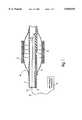
- the apparatuscomprises a catheter having a shaping element positioned near its distal end.
- the polymeric materialis positioned adjacent or near the shaping element, illuminated by light delivered by the catheter and thus heated to render it fluent, and molded by the shaping element into contact with a tissue lumen.
- the apparatuscomprises a balloon dilatation catheter having an associated optical tip assembly.
- the polymeric materialis positioned on the balloon, preferably in the form of a tube or sleeve which surrounds the balloon.
- the optical tip assemblyserves to direct light to the polymeric material.
- the lightmay be provided from an external source.
- the polymeric materialis heated to a temperature at which it becomes moldable. Inflation of the balloon causes the moldable polymeric material to expand outwardly, thereby pressing the polymer into contact with the tissue lumen.
- the polymeric materialin cases in which the polymeric material can be reconfigured prior to molding (i.e., the polymeric material comprises a rolled sheet or a tube having axial pleats), the material is reconfigured using the balloon and then heated to mold it into conformance with an adjacent tissue surface.
- the apparatusfurther includes a retractable sheath which is designed to encapsulate the polymeric material on the balloon as the material is guided to a treatment location in vivo. Once positioned, the sheath is retracted to expose the material and to allow the material to be heated and molded as described above.
- the sheathmay include a tapered distal tip, formed of a flexible polymer, which expands radially over the balloon and polymeric material as the sheath is withdrawn over those structures.
- the tipmay include at least one longitudinal slit which allows radial expansion of the tip.
- FIG. 1illustrates one embodiment of a laser balloon catheter suitable for delivery of a polymeric material
- FIGS. 2a and 2billustrate one embodiment of a laser balloon catheter suitable for delivery of a to polymeric material
- FIG. 3is an illustration of a laser balloon catheter showing two embodiments of an optical emitter
- FIGS. 4a and 4billustrate a second embodiment of a laser balloon catheter suitable for delivery of a polymeric material
- FIGS. 5a and 5billustrate a retractable sheath suitable for use with the laser balloon catheters of FIGS. 1, 2 and 4;
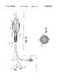
- FIGS. 6a and 6bare schematic illustrations of another embodiment of a device for providing a thick polymeric film on a luminal wall.
- FIGS. 7a and 7bare schematic representations of an optical emitter catheter for use with the device of FIG. 6b.
- the ability to selectively heat an implanted polymeric material using light in the visible or near-visible spectrumcan be achieved using a light source which produces a wavelength spectrum that is not readily absorbed by body tissue.
- Light from the sourceis used to heat a polymeric material that is at least partially absorptive of the light in the spectral range. Even if only a portion of the light (e.g., 50%) is absorbed by the polymer, transmitted light will not be readily absorbed by the surrounding tissue and will have a minimal heating effect on that tissue. In this case, light which is not absorbed by the polymer is absorbed by a relatively large area of tissue as it penetrates beyond the polymer. As such, resultant heating occurs throughout a much larger volume of tissue.
- the temperature rise in the tissueis a function of energy absorbed within a unit volume of tissue, localized heating is significantly lower as compared to the heating caused by wavelengths that are readily absorbed, i.e., by a smaller volume of tissue.
- the requirement for wavelengths which have low tissue absorption characteristicsis necessary only to the extent that excess heating of the tissue does not occur or is undesirable at the particular treatment location.
- the polymeric materialis highly absorptive of light in the spectral range.
- the polymerwill absorb substantially all of the light, thereby minimizing the amount that is transferred to the body tissue and minimizing the heating effect of that light on tissue.
- the polymeric materials of the present inventionmust satisfy various criteria, including molding temperature, crystallinity, absorption characteristics, bioerodability, physical strength, biocompatibility and light transmission and absorption characteristics. Each of these are discussed below.
- the materialmust become either moldable or molten at a temperature that is not significantly injurious to tissue or surrounding physiological fluids if maintained at that temperature for the amount of time required to implant and shape the material. Additionally, the material must become moldable at a temperature above about 40 degrees C. That temperature has been selected as being a temperature that is greater than body temperatures associated with hyperthermia or fever (approximately 38-40 degrees C.). The requirement of the minimum molding temperature is to prevent the material from spontaneously softening or melting in response to elevated, physiologically occurring body temperatures.
- melting temperatureis used to describe a minimum melting temperature, T m , or a glass transition temperature, T g , at which the polymer may be plastically deformed using physiologically acceptable forces. Likewise, the melting or glass transition temperature are must be below that at which significant mechanical or thermal damage to body tissues occurs.
- thermalformingis used to describe the process wherein a polymeric article is heated to at least its molding temperature and then reshaped by external or internal forces.
- the materialhave a substantially crystalline or semi-crystalline structure so that when heated to its melting temperature, it will undergo a rapid transition to a viscous fluid that will flow readily, yet remain cohesive, when subjected to molding forces associated with thermoforming.
- the materialmay be glassy or have a glassy component. In that case, if heated sufficiently above its glass transition temperature, the material will also flow readily and remain cohesive when subjected to molding forces.
- the materials useful in the inventionare termed "fluent" when in their moldable state.
- the actual viscosity of the fluent material that allows the material to be molded without significant mechanical disruption of the tissuedepends upon the particular tissue and the method by which the material is molded.
- the materialbe such that, once heated to its molding temperature, (i.e., rendered fluent), the material may be shaped or formed using a physiologically acceptable amount of force.
- the molding temperaturebe low enough to prevent significant thermal damage during the molding process. The ability to be molded using a minimum amount of force reduces the possibility of tissue injury potentially occurring as a result of misuse or structural failure of the polymeric material or the force-supplying component.
- Determination of an acceptable amount of force and thermal loaddepends upon at least a) the viscosity of the material in its moldable state, b) the length and/or thickness of the material, c) the geometric configuration of the material, and d) the temperature at which the material becomes sufficiently fluent. Additionally, forces and thermal loads that may be physiologically acceptable on one type of tissue may not be acceptable on another. For example, physiologically acceptable forces and temperatures within bone tissue may far exceed the amount of force and heat that is physiologically acceptable on a blood vessel or other soft tissue. Thus, the physical characteristics of both the polymeric material and the tissue site must be considered in determining maximum physiologically acceptable forces and temperatures for molding the polymer.
- the selected polymeric materialbe such that the amount of thermal energy needed to heat the material to its molding point can be transferred within a practical amount of time to thereby minimize the length of time required for the surgical procedure and to minimize the amount of heat conducted out of the material and into the tissue.
- the materialis intended to provide mechanical support to tissue structures.
- the material itself, and the ultimate therapeutic shape of the materialmust provide a structure having sufficient mechanical strength to withstand forces exerted upon the shaped material during its functional lifetime in vivo. This requirement is especially significant when using materials that are expected to be biodegradeable after their mechanically functional lifetime.
- the materialneed not be intended for structural support. Rather, the material may be used as a protective layer, a barrier layer, as an adhesive, or as a carrier of therapeutic agents. In that case, the material must be selected so that its function is not impaired either by biodegradation during its functional lifetime in vivo or by the process used to shape the material during implantation.
- the ability to provide varied degrees of mechanical supportcan be achieved by selecting differing polymeric materials or by altering the molecular weight distribution of materials comprising more than one polymer. In general, materials having higher molecular weights will provide a higher modulus and greater support than those materials having a lower molecular weight. Additionally, the material must be selected such that the heating and reformation of the material do not degrade or otherwise alter the release characteristics of the material toward any therapeutic agents that may be incorporated into the material.
- the materialnot completely cover, but only partially cover an area of tissue to be supported or otherwise addressed by the material.
- the materialmay be applied to support a portion of a tissue lumen, rather than the entire lumen.
- the physical formmay be varied to suit the final application. While relatively thin solid films or sheets are preferred for many applications, fenestrated or microporous sheets may also be used. Spun webs, with or without melt-bonding or calendaring, may also be of use.
- the materialcan include predefined perforations or apertures once transformed from a delivery configuration to its therapeutic configuration.
- the cylindermay be provided with a plurality of perforations which open or remain open once the cylinder has been expanded to a larger, therapeutic configuration. If the material is used as a support structure for an artery, the perforations may allow increased axial flexibility to facilitate delivery and reduce tissue erosion during and after implementation, improved perfusion of side branch vessels by decreasing the likelihood of obstruction of such vessels, and increased ingrowth of tissue for anchoring and encapsulation of the material.
- the polymeric materialshould preferably absorb light within a wavelength range that is not readily absorbed by tissue, blood elements, physiological fluids, or water. Although wavelengths in the spectral range of about 250-1300 nm may be used, wavelengths in the range of about 300-1000 nm are preferred, and wavelengths in the range of about 500-850 are especially preferred. In the case in which a chromophore such as a dye or pigment is incorporated into the polymeric material, the material itself must be sufficiently transparent to allow the light to reach and be absorbed by the dye or pigment.
- chromophores and light sources suitable for use in the inventionmay be selected from dye or pigment materials and lasers corresponding to those materials including, but not limited to, the following:
- any of a variety of methods known in the art of polymer processingmay be used to form the polymeric material into its predeployment configuration and, if necessary, to compound chromophores into the material.
- the polymer processing methods contemplatedare solvent casting, injection molding, extrusion, solvent extraction and compression molding.
- the heating method of the present inventionmay be contrasted with conductive heating methods which use a heating element, as such techniques tend to require a greater thermal load and to heat more slowly, thereby having the potential to transfer significant amounts of heat to the surrounding body tissue or fluids, As noted previously however, absorption of light allows the polymeric article to be heated while transferring a minimum of energy to the surrounding tissue and fluids. This is achieved by selecting either a wavelength spectrum that is not readily absorbed by body tissue, a polymeric composition that absorbs substantially all incident energy in the wavelength spectrum, or a combination of these characteristics.
- the upper limit of the polymer temperaturecan be controlled using a dye which substantially stops absorbing optical energy once it reaches a certain temperature.
- a dye which substantially stops absorbing optical energySuch so-called "thermochromic" dyes are commercially available from Clark R&D Limited of Arlington Heights, Ill. Thermochromic dyes exhibit a constant absorption below a lower critical temperature T L . Between T L and an upper critical temperature T U the absorption decreases from a constant value to nearly zero. Thermochromic dyes are further characterized generally in that the change of absorption with temperature is fully reversible. The incorporation of thermochromic dyes into polymeric materials allows constant absorption of energy when the polymer is cool with a decreasing energy absorption as the polymer is heated. It is expected that the polymer temperature will reach a steady state at some point between T L and T U resulting from a balance between the energy absorbed by heat input from the light source and the energy lost by heat output to the surrounding tissue.
- Type 47 thermochromic dyeavailable from Clark R&D absorbs, at room temperature, light in the wavelength spectrum between about 600 and about 850 nm.
- the dyehas a T L of 44 degrees C. and a T U of 58 degrees C. If this dye is compounded into a polymer having a melting temperature (T M ) that falls between T L and T U , the resulting polymeric material will absorb light in the 600-850 nm spectrum and begin to heat. Once the polymeric material is heated to a temperature above T L , the absorption of the dye will decrease, thereby decreasing the rate of polymeric heating and preventing the polymeric material from achieving a temperature that may be harmful to it, and adjacent body tissue or surrounding body fluids.
- T Mmelting temperature
- the polymermelts, allowing it to pave an adjacent tissue surface.
- the temperature risewill decrease and reach a steady state level where the energy input (reduced due to decreased dye absorption) equals the energy output (mediated by thermal boundary conditions) an upper thermal limit is achieved.
- Thermochromismthus is essentially a feedback mechanism for obtaining uniform heating of the entire article despite possible non-uniformity of illumination.
- the hottest regions of the polymerwill absorb less light, allowing other areas of the device to "catch up" in temperature during the heating stage.
- Thermochromic dyescan render instrumentation to measure temperature of the polymeric material unnecessary.
- thermochromic dyesmay offer advantages if the emitter is eccentrically located inside a shaping element such as a balloon. Since power density from the emitter is approximately related to the inverse or the inverse square of the distance between the emitter and the polymeric material, the power density would be much higher for a portion of polymeric material close to the emitter than for a portion of the material that is further away. When using conventional dyes, the result can be a non-uniform temperature around the shaping element, resulting in one portion of the polymeric material being much warmer than another.
- thermochromic dyeif a thermochromic dye is incorporated into the polymeric material, the material that is located closer to the emitter would rapidly reach its maximum temperature and level off, while material on a further portion of the polymeric material would reach the same maximum temperature, although more slowly. The result is that ultimately the entire polymeric article would reach a uniform temperature.
- different thermal boundary conditions at the surface onto which the polymeric article is being appliedcould also, if conventional dyes are used, cause the polymeric article to become warmer in some sections than in others. This difference can also be reduced if thermochromic dyes are employed.
- thermochromic dyecan be used in combination with a conventional dye.
- a combination of thermochromic and conventional dyeswould cause the heating to slow as the absorption of the thermochromic dye decreases.
- the heating levelwould continue to increase as a result of the presence of the conventional dye until a steady state is reached.
- the polymeric materials of the inventionpreferably are bioerodable.
- bioerodableas used herein is intended to encompass many modes of material removal, such as enzymatic and non-enzymatic hydrolysis, oxidation, and enzymatically-assisted oxidation. It is thus intended to include degradation, bioresorption and dissolution.
- the polymeric materialsare to be bioerodable, they should be selected on the basis of their degradation characteristics to provide a sufficient functional lifespan for the particular application. In the case of arterial applications, a functional lifespan of 3-6 months is believed to be sufficient. In other therapeutic applications, (i.e., trachial, urinary, bronchial, bone lumens and the like) shorter or longer periods may be appropriate.
- Suitable bioerodable polymeric materialsinclude, but are not limited to, polymers, copolymers and blends of:
- Polyanhydridesespecially those made using melt condensation, solution polymerization, or with the use of coupling agents, aromatic acids, aliphatic diacids, amino acids (such as aspartic acid and glutamic acid), and the copolymers thereof).
- GPolyoxyalkylenes, where alkene is 1 to 4 carbons, as homopolymers and copolymers including graft copolymers.
- Suitable non-bioerodable polymeric materialsinclude, but are not limited to, polymers, copolymers and blends of:
- Polycaprolactone homopolymers and copolymersare highly suitable bioabsorbable polymers for use in accordance with the invention, particularly for the prevention of abrupt closure or restenosis in a blood vessel, or for the creation of radially expanded lumens through a blood vessel, trachea, urethra or other tissue lumen.
- Such materialspossess adequate strength in their solid form to structurally support soft tissue lumens.
- the physical structure of such materialsis sufficiently non-variable, in the period prior to its bioerosion, to maintain constant dimensions in the molded article.
- the materialsprovide structures such as stents that, although flexible, do not significantly deform in the period between implantation and degradation.
- Such dimensionally stable, shaped articleseliminate risks associated with known helical or spring metal stents which may have a tendency to continue to expand once positioned in a lumen, thereby exerting continuous or increasing pressures on the lumen wall.
- polymeric stents of the type describedconform, when fluent, to lumen irregularities. In the case of blood vessels, such conformity tends to avoid causing blood flow discontinuities which can contribute to thrombus formation.
- Stents formed of structural metallic or polymeric filamentsdo not closely conform to the lumen, thereby creating areas of blood stagnation and turbulence.
- Polycaprolactoneshave a crystalline melting point of approximately 60 degrees C. and can be deployed in vivo using the methods described herein. Additionally, such materials in their fluent state are well adapted for mechanical deformation to various degrees and into various configurations.
- Polycaprolactone homopolymers and copolymersbioabsorb at rates that are advantageous in many applications in which biodegradability is desired. These materials can be designed to resorb as soon as three months after implantation or as long as three years after implantation. For example, polycaprolactone copolymerized with lactic or glycolic acids may resorb over a 3--9 month period, whereas polycaprolactone homopolymers may resorb over a 2-3 year period.
- the ultimate degradation product of polycaprolactonesis a non-toxic, 6-hydroxy hexanoic acid having a pH close to neutral.
- bioabsorbable polymerssuch as polygycolides and polylactides melt at temperatures on the order of approximately 180 degrees C., a temperature well above that tolerable by human tissue.
- these materialshave glass transition temperatures of approximately 45 degrees C., thus they are moldable at physiologically tolerable temperatures and potentially useful in practising the methods of the invention.
- polyanhydridesmay be used. These materials are knows for use as drug carrier matrices, and frequently have low glass transition temperatures (in some cases near normal body temperature) which makes them mechanically deformable with only a minimum of localized heating. Furthermore, polyanhydrides offer biodegradation times spanning from several months to several years depending on the particular polymer selected.
- copolymerizationmay be used to alter the molding temperature of many families of polymers. For example, although poly(epsilon caprolactone) homopolymers exhibit a melting temperature of approximately 60 degrees C., poly(epsilon caprolactone-co-lactic acid) copolymers containing approximately 20% lactic acid exhibit a reduced melting temperature of approximately 45-50 degrees C.
- the polymeric materialis a polycaprolactone polymer having an indocyanine green or copper phthalocyanine dye compounded therein.
- Such dyesreadily absorb light in the 780-800 nm wavelength range, a range that is available from semiconductor diode lasers. Furthermore, wavelengths in this range are not readily absorbed by body tissues or fluids, thus the possibility of physiologically intolerable levels of heating by absorption of the light energy by such tissues and fluids is minimized.
- thermoformed polymeric structureIt is advantageous in some cases to deliver a drug or other therapeutic agent from the thermoformed polymeric structure.
- Such deliveryhas advantages that are well-known to those skilled in the art of drug delivery, including the ability to deliver the therapeutic agent to a specific location in the body and to achieve concentrations of the agent that are locally higher than could be attained practically and safely when the agent is delivered systemically.
- Intended therapeutic agentsinclude, but are not limited to, growth factors and growth factor antagonists, mitotic and antimitotic agents, antibiotics, antimycotics, antioxidants, anti-inflammatory agents, and substrate analogs for enzymes or receptors.
- the polymeric paving and sealing materialmay incorporate therapeutic agents such as drugs, drug producing cells, cell regeneration factors or even progenitor cells of the same type as the involved organ or histologically different to accelerate healing processes
- therapeutic agentssuch as drugs, drug producing cells, cell regeneration factors or even progenitor cells of the same type as the involved organ or histologically different to accelerate healing processes
- Such materials with incorporated therapeutic agentsmay be effectively used to coat or plug surgically or traumatically formed lumens in normally solid organs as well as the native or disease generated lumens of hollow or tubular organs.
- the polymeric material used in PEPScan be combined with a variety of therapeutic agents for on-site delivery.
- therapeutic agentsfor on-site delivery.
- examples for use in coronary artery applicationsare anti-thrombotic agents, e.g., prostacyclin and salicylates, thrombolytic agents e.g. streptokinase, urokinase, tissue plasminogen activator (TPA) and anisoylated plasminogen-streptokinase activator complex (APSAC), vasodilating agents i.e. nitrates, calcium channel blocking drugs, anti-proliferative agents i.e.
- anti-thrombotic agentse.g., prostacyclin and salicylates
- thrombolytic agentse.g. streptokinase, urokinase, tissue plasminogen activator (TPA) and anisoylated plasminogen-streptokinase activator complex (
- colchicine and alkylating agentsintercalating agents, growth modulating factors such as interleukins, transformation growth factor 8 and congeners of platelet derived growth factor, monoclonal antibodies directed against-growth factors, anti-flammatory agents, both steroidal and non-steroidal, and other agents which may modulate vessel tone, function, arteriosclerosis, and the healing response to vessel or organ injury post intervention.
- growth modulating factorssuch as interleukins
- monoclonal antibodies directed against-growth factorsanti-flammatory agents
- anti-flammatory agentsboth steroidal and non-steroidal
- PEPSmay be used to effect pharmaceutical delivery focally within the vessel wall, i.e. media.
- the polymeric material in accordance with the inventionmay also have incorporated in it living cells to serve any of several purposes.
- the cellsmay be selected, or indeed designed using principles of recombinant DNA technology, to produce specific agents such as growth factors. In such a way, a continuously regenerating supply of a therapeutic agent may be provided without concerns for stability, initial overdosing and the like.
- Cells incorporated in the polymeric materialmay also be progenitor cells corresponding to the type of tissue in the lumen treated or other cells providing therapeutic advantage.
- liver cellsmight be implanted in the polymeric material within a lumen created in the liver of a patient to facilitate regeneration and closure of that lumen. This might be an appropriate therapy in the case where scar tissue or other diseased, e.g., cirrhosis, fibrosis, cystic disease or malignancy, or non-functional tissue segment has formed in the liver or other organ and must be removed.
- the process of carrying out such treatmentinvolves first inserting a catheter into a lumen within a diseased organ segment.
- the lumencan be a native vessel, or it can be a man-made lumen, for example a cavity produced by a laser.
- the catheteris used to introduce a polymeric plug into the lumen.
- the catheteris then removed, leaving the plug in place to act as a focus for new growth stemming from cells implanted along with the polymeric plug. If the desire is for a more tubular structure, the plug can be appropriately reconfigured.
- the polymeric materialcan incorporate biologically active molecules to impart additional properties to the polymer, such as resistance to bacterial growth or decrease in inflammatory response, as well as to encapsulate tissues.
- biologically active materialcan be encapsulated or incorporated, including proteins, peptides, polysaccharides, organic or inorganic drugs, nucleic acids, sugars, cells, and tissues.
- Examples of cells which can be encapsulatedinclude primary cultures as well as established cell lines, including transformed cells. These include but are not limited to pancreatic islet cells, human foreskin fibroblasts, Chinese hamster ovary cells, beta cell insulomas, lymphoblastic leukemia cells, mouse 3T3 fibroblasts, dopamine secreting ventral mesencephalon cells, neuroblastoid cells, adrenal medulla cells, and T-cells. As can be seen from this partial list, cells of all types, including dermal, neural, blood, organ, muscle, glandular, reproductive, and immune system cells, as well as species of origin, can be encapsulated successfully by this method.
- proteins which can be encapsulatedinclude hemoglobin, enzymes such as adenosine deaminase, enzyme systems, blood clotting factors, inhibitors or clot dissolving agents such as streptokinase and tissue plasminogen activator, antigens for immunization, and hormones, polysaccharides such as heparin, oligonucleotides such as antisense, bacteria and other microbial organisms, including viruses, vitamins, cofactors, and retroviruses For gene therapy can be encapsulated by these techniques.
- the biological materialcan be first enclosed in a structure such as a polysaccharide gel.
- a structuresuch as a polysaccharide gel.
- Such gelscan provide additional structural protection to the material, as well as a secondary level of perm-selectivity.
- a second preferred applicationconcerns a method of locally applying a biologically active substance to tissue surfaces of a patient.
- the biologically active substancecan be any of a variety of materials, including proteins, carbohydrates, nucleic acids, and inorganic and organic biologically active molecules. Specific examples include enzymes, antibiotics, antineoplastic agents, local anesthetics, hormones, antiangiogenic agents, antibodies, neurotransmitters, psychoactive drugs, drugs affecting reproductive organs, and oligonucleotides such as antisense oligonucleotides.
- the polymeric materialmay comprise a stent that is applied to the interior of a blood vessel following treatment of a stenosis by angioplasty.
- the materialis provided in the form of a hollow sleeve having a diameter that allows it to be guided through a blood vessel using percutaneous transluminal techniques.
- the sleeveis heated to its molding temperature and radially expanded into contact with the wall of the vessel. Once expanded, the device is allowed to cool and become non-fluent, or harden, thereby providing a vessel lining that offers structural support to maintain the vessel open and facilitate blood flow. As such, the device prevents abrupt post-surgical closure of the vessel.
- the materialmay be expanded prior to heating and molding, this alternative being described in greater detail hereinafter.
- the applied liningsuch as a vascular lining may incorporate various therapeutic and pharmaceutical agents to provide a means for local delivery of such agents at the treatment site.
- agentsmay be employed to further reduce the likelihood of restenosis or other unwanted conditions at the site.
- Thesemay be incorporated in the device, or coated onto or absorbed into it.
- the devicemay have multiple layers to control migration of the therapeutic agent.
- the liningmay also serve to isolate the vessel wall from physiological fluids, and in so doing, may avoid one mechanism for restenosis.
- the mechanisms for restenosisremain unclear, there is some evidence to suggest that angioplasty damages portions of the blood vessel, and these damaged portions become sites for cell growth via interaction with certain components in the bloodstream. If the damaged vessel portion is isolated from the bloodstream, the possibility exists that initiation of restenosis may be avoided. Linings of this sort may be thinner, or less strong, than layers intended for use as structural supports.
- the device and methodsare used in intravascular therapy in situations where a guidewire is present, such as would be the case after a balloon angioplasty procedure. It is noted, however, that other cardiovascular treatments may not require certain elements shown in the figures. For example, if a catheter such as a guiding or sheath catheter remains in position from an earlier procedure, the guidewire (and thus the guidewire lumen) may not be necessary. Likewise, a central lumen may not be required if photothermoforming processes and materials are used in other organ systems, such as the intestines. Additionally, the devices depicted in the figures may include other features such as sensor or detector systems, or bypass lumens.
- the polymeric materialmay be delivered to the target site via a laser balloon catheter as shown in FIG. 1.
- the device 10comprises an elongated flexible tube 11 (i.e., a catheter) having an article shaping element which comprises, for example, a radially expandable, inflatable balloon 12 positioned at its distal end.
- the tube 11includes an inflation lumen 13 through which the balloon 12 may be inflated,
- the tube 11also includes a central lumen 14 adapted to engage a guide wire.
- the central lumen 14also allows passage by an optical tip assembly 15 which comprises a radial light diffuser 16 connected to a light source/controller 17 via an optical fiber 18.
- the radial light diffuser 16may comprise a flexible, translucent tube containing a light-scattering filler such as those described below with respect to FIGS. 2a and 2b.
- the diffuser 16contains a transparent or translucent adhesive containing light-scattering TiO 2 particles.
- the optical fiber 18is connected between the high source/controller 17 and the radial diffuser 16 and serves to transmit light between the source and the diffuser. When activated, the source produces light which travels through the optical fiber 18 and into the diffuser 16 causing the light to be scattered in a generally uniform, radial manner.
- portions of the diffusermay be masked or otherwise rendered non-translucent to produce radial or axial non-uniformities in the scattered light. Both the balloon 12 and the portion of the tube 11 in the region of the balloon should be substantially transparent to the light emitted from the diffuser.
- the device 21comprises an outer elongated flexible tube 20 (i.e., a catheter) and an inner elongated flexible tube 22 positioned within the lumen of the outer tube 20.
- the inner tube 22is longer than the outer tube 20 so as to cause its distal end 23 to extend distally beyond the distal end of the outer tube 20.
- An article shaping elementfor example a radially expandable, inflatable balloon 24 is mounted on the distal end of the device such that the proximal end of the balloon 24 is secured near the distal end of the outer tube, and the distal end of the balloon is secured near the distal end of the inner tube.
- a moldable polymeric article 19is positioned on the balloon prior to its implantation at a desired treatment location.
- the annular space formed between the inner wall of the outer tube and the outer wall of the inner tubeforms an inflation lumen 25 through which the balloon may be inflated and expanded,
- Positioned within the annular spaceis at least one, and preferably a plurality of optical fibers 26 which extend from the proximal end of the device and have distal ends which communicate with an optical emitter assembly 28.
- the optical emitter 28is positioned within the interior of the balloon and preferably comprises an integral part of the inner tube 22 in the region in which the inner tube passes through the balloon.
- the article shaping elementis not intended to be limited solely to a radially expandable balloon. Numerous other shaping elements, including but not limited to malecots and the like are contemplated as well.
- the optical emitter 28delivers diffuse light within the shaping element and comprises a flexible, translucent tube 30 containing a light-scattering filler 32.
- the fillercan comprise a translucent matrix containing light-scattering media such as titanium dioxide (TiO 2 ) particles.
- Other light scattering mediainclude Zr 2 O 3 , Ba 2 SO 4 , diamond dust, glass beads, and combinations thereof, with or without TiO 2 .
- the translucent matrixcan comprise, for example, an epoxy or other polymeric material which fills the annular gap between the translucent tube 30 and the inner tube 22, thereby forming the emitter as an integral element of the inner tube.
- the proximal end of the deviceincludes a hub assembly 27 having a port 31 to access the lumen through inner tube 22, a balloon inflation port 33 communicating with inflation lumen 25, and an optical fiber connector 35 which is attachable to a light source (not shown) to provide light through the optical fibers 26 to the optical emitter 28.
- the emittermay comprise the distal end of the inner tube, in the portion extending through the balloon and beyond its distal end.
- the emitter 28is affixed to the distal end of a catheter tube 40 using a taper joint 41, a lap joint, or other known joint structures to form a tubular assembly having a light diffusing distal end.
- the emitterpreferably comprises a translucent polymer having an inherent light-scattering characteristic or a light-scattering medium compounded therein.
- Optical fibers 26 communicating with the emitterare provided within the annular space between the outer and inner tubes or within lumens provided in the inner tube.
- the catheter tube 40may be translucent with light-scattering characteristics along all or part of its length.
- the emitteris defined as that portion 29 of the tube 40 located distally to the distal ends of the optical fibers.
- the distal ends of the optical fibers 26terminate within the light-scattering filler to allow light exiting from the fibers to be scattered in a substantially uniform radial manner.
- a light source/controller(not shown) is connected to the proximal ends of the fibers and serves to transmit light through the fibers into the emitter.
- the emitterneed not comprise a tube filled with a scattering material. Rather, a solid tube or annular sleeve of a material having inherent scattering properties such as polyethylene or PTFE may be substituted.
- the flexible, translucent tube 30 of the emittercomprises a flexible material which minimizes absorption of light in the wavelength spectrum provided by the light source/controller.
- Numerous translucent polymeric materialscan be used, including polyethylenes (PE), polyethylene terephthalates (PET), and polyfluoroalkylenes such as PTFE. Polyethylene is preferred.
- the light scattering filler 32preferably comprises a transparent or translucent matrix, for example an epoxy adhesive, containing the light-scattering particles. The filler 32 is contained in the annular space created between the interior of the emitter tube 30 and the exterior of the inner tube 22.
- the matrix containing the light-scattering particlesmust be substantially transparent to the wavelength spectrum of light produced by the light source/controller.
- the balloon itself and its inflation mediummust be transparent to the light in order to allow the light to pass through the balloon and heat the polymeric particle positioned on the balloon.
- a preferred inflation mediumcomprises a mixture of equal parts of saline and an iodinated contrast agent. Such a mixture is sufficiently transparent to light from the emitter and also radiopaque to aid fluoroscopic visualization.
- the emittermay be formed integrally with the distal end of the optical fibers themselves.
- the distal end of the fibersmay be chemically or mechanically modified in a manner which causes the fibers to radiate laterally in the region of the modification.
- the distal end of the fibersmay be ground or chemically modified to "frost" the fiber, thereby to provide light scattering sites directly on the fiber surface.
- Optical fibers modified in this mannersimplify manufacture of the devices in that the need to assemble a separate optical emitter for use with the device is eliminated.
- the inner tube 22, at least in the region of the optical emitter 28,is transparent to light in the wavelength spectrum being used to prevent "shadowing" of the light.
- a reflective coatingmay be armed about the inner tube 22 in the region of the optical emitter to reflect back any light scattered toward the inner cube 22 by the light scattering medium. If the inner tube 22 is translucent, the reflective coating can be provided on the inner surface of the tube. For light in the visible spectrum, the reflective coating preferably comprises a thin coating of silver, and for light in the infrared spectrum, the reflective coating preferably comprises a thin coating of gold.
- Such coatingscan be deposited using any of a variety of known methods for depositing metal on polymeric surfaces, including but not limited to sputtering, ion bombardment, and ion-assisted vapor deposition. It is noted that these modifications are not mandatory, however, as satisfactory results can still be achieved even if the inner tube 22 in the region of the optical emitter 28 is not reflective of or translucent to the light. If the inner tube absorbs light in the wavelength spectrum provided to the polymeric article 36, the tube must be fabricated of a material that has a melting or glass transition temperature sufficiently high to avoid deformation of the tube during the heating and forming process.
- a radiopaque marker 34such as a band or ring or tantalum, gold, tungsten or silver, may be positioned on the device in order to aid the physician in determining the location of the distal end of the device during an implantation procedure. As shown in FIG. 2a, the radiopaque marker may be positioned within the interior of the balloon, however, other positions may be used as well. Furthermore, the device is not limited to the use of a single marker, but rather may make use of a number of such markers positioned at various places on the device.
- the first and second elongated tubescan be formed of polymeric materials comprising, for example, polyethylenes, nylons, polyvinyl chlorides, polyether block amides, polyurethane, and combinations and copolymers thereof.
- the balloonpreferably comprises a polymeric material such as polyethylene terephthalate, crosslinked polyethylene or composites thereof.
- the balloonmay have a coating formed of a low surface energy material on its outer surface.
- coatingsinclude surfactants, hydrogels, fluoropolymers or silicone-based coatings.
- the surface of the balloonmay be modified to a low energy surface using a plasma treatment, or the balloon itself may be made of a material with low surface energy (i.e., crosslinked polyethylene). Likewise a low surface energy properties can be provided on the polymeric article on surfaces which contact the balloon.
- the implantation device 50can comprise an elongated tubular body 52 having at least two lumens extending from its proximal end.
- a central lumen 54extends through the entire length of the tube, thereby allowing fluids and devices, such as guidewires, to pass entirely through the tube.
- At least one balloon inflation lumen 56provides communication between the proximal end of the tube 52 and the interior of a radially expandable balloon 58 mounted near the distal end of the device.
- An optical emitter 60is positioned within the balloon and serves to scatter light provided by at least one, and preferably a plurality of optical fibers 62 in a substantially uniform manner.
- the optical fiberscan communicate with the emitter 60 either through the balloon inflation lumen 56, or, in the alternative, through a separate optical fiber lumen provided in the tubular body 52.
- a moldable polymeric article 36is positioned on the balloon 58 prior to its implantation at a desired treatment location.
- the optical emitter 60may surround a portion of the tube 52 passing through the balloon, or, in the alternative, it can comprise the distal portion of the tube.
- the emittercan be of similar constructions as those described in connection with the earlier embodiments and as depicted in FIGS. 2a and 2b or FIG. 3.
- one or more radiopaque markers 66such as tantalum bands, may be positioned on the device to aid the physician in determining the location of the distal end of the device during an implantation procedure.
- the proximal end of the deviceincludes a hub assembly 27 having a lumen access port 31 to access the central lumen 54, a balloon inflation port 33 communicating with one or more balloon inflation lumens 56, and an optical fiber connector 35 in communication with the optical fibers 26.
- chilled fluidsuch as saline may be introduced into a first balloon lumen, allowed to flow through the balloon, and to exit the balloon through a second lumen.
- chilled fluidsuch as saline may be introduced into a first balloon lumen, allowed to flow through the balloon, and to exit the balloon through a second lumen.
- the polymeric articlemay be cooled, hastening its return to a non-fluent state and potentially preventing or minimizing thermal damage to tissue.
- the deviceneed not be limited solely to catheters having a central lumen passing entirely though the catheter shaft.
- the catheterscan include a separate, shorter lumen having one end which exits the catheter at or near the distal end of the catheter shaft and a second opening somewhat proximal to the distal end of the shaft.
- Such so-called “rapid exchange” or “monorail” cathetersare designed to facilitate catheter exchanges while maintaining positioning of a guidewire.
- Monorail cathetersare known in the art, being described, for example, in U.S. Pat. No. 4,762,129 to Bonzel.
- portions of the emitter or the shaping elementoptionally can be masked or otherwise rendered nor-translucent to produce radial or axial non-uniformities in the scattered light if non-uniform heating of the polymeric article 36 is desired.
- the devicecan be used as follows.
- the balloonis deflated and a polymeric article is positioned about its exterior.
- the balloon carrying the polymeric articleis then advanced through a body lumen to position the polymeric article at a desired treatment location.
- light energyis supplied from the source through the optical fibers to the optical emitter or optical tip assembly.
- the lightdiffuses outwardly from the emitter and through the balloon (and through a tube according to the embodiment illustrated in FIG. 1).
- the light energyis absorbed by the polymeric material or by chromophores contained in the material. The energy absorption heats the polymeric material to at least its molding temperature.
- the balloonis inflated fully, thereby molding the material into conforming contact with the adjacent tissue surface.
- the articlemay be rapidly bulk heated with only minor conductive loss of heat to the surrounding tissue.
- the balloonmay be pressurized prior to heating of the polymeric article.
- the pressurized balloonpresses against the interior surface of the polymeric article which yields upon subsequent heating to its melting or glass transition temperature, thereby allowing the balloon to mold the material into conforming contact with the adjacent tissue surface.
- the polymeric articleis of a shape that can be expanded prior to becoming moldable, the article can be guided to a desired treatment location and then expanded by a partial inflation of the balloon. Upon heating the article to its molding temperature, the balloon can then be fully inflated, hereby molding the previously expanded article into conforming contact with an adjacent tissue surface.
- the polymeric articlemay comprise a relatively thin sheet of material that is positioned upon a tissue surface during a surgical procedure. Upon heating to a temperature above its molding temperature, the sheet may be pressed against the tissue surface, thereby causing it to conform to the surface shape. Alternatively, the sheet may be rolled about the balloon portion of the previously described balloon catheter.
- the sheetUpon heating to its molding temperature and expansion of the balloon, the sheet is caused to unroll and to be pressed into conforming contact with the interior of a body lumen.
- the ends of the sheetmay be sealed to form a tubular structure.
- the articlemay comprise a pleated, accordion-like shape which upon heating may be expanded to cover a surface.
- the sheet or pleated articlemay be first expanded, and then heated and molded in the manner described above.
- the devicemay include an elongated retractable sheath as an aid to maintaining the polymeric article on the balloon during the period at which the device is guided to the treatment location.
- the sheath 80comprises a retractable elongated tube which is operatively coupled to or extends from the proximal end of the implantation device to a point distally beyond the shaping element.
- the distal end 82 of the implantation devicemay extend a short distance beyond the end of the sheath.
- the sheathoptionally can include a tapered distal tip 84 formed of a relatively soft, radially expandable material that may include at least one longitudinal slit 85 formed therein.
- the tipis affixed to the distal end of the sheath using, for example, a taper or lap joint.
- the tip 84can be an integral part of the sheath 80.
- the use of a soft, pliable material and/or slitsallows the tit to expand radially, thereby allowing the sheath to be withdrawn over the shaping element.
- the tapering of the tipprovides a shaped surface which is adapted to minimize the possibility of damage as the distal end of the device is guided through a tissue lumen by providing a low profile leading edge.
- the hub assembly 27is as described above. However, an additional hub 81 is provided. Additional hub 81 is operatively connected to sheath 80 and serves as an actuator to retract the sheath and also as a hemostatic valve. A collar 83 positioned at the proximal end of hub 81 allows the practitioner to retract the sheath 80 and expose at least a portion of the implantable polymeric article 36. An optional port 87, in communication with the interior of the sheath, is provided. The port 87 allows fluid to be injected between the sheath and the portion of the device surrounded by the sheath if so desired.
- the sheathis retracted to expose at least the article 36 and the underlying balloon 86.
- the tipis radially expandable with a minimum of force to allow the sheath to be retracted, thereby pulling the tip over the polymeric article, without dislodging the article from the balloon.
- the sheathis preferably formed of a polymeric material selected from the group consisting of fluoropolymers, high density polyethylenes, polyether block amides, polyurethanes, thermoplastic elastomers, and combinations and copolymers thereof.
- the tapered distal tippreferably is formed of soft, flexible materials such as natural or synthetic rubbers, silicones, polyether block amides, polyurethanes, thermoplastic elastomers, and combinations and copolymers thereof.
- retractable sheathis optional, as static friction between the article and the balloon may be such that the article will not become dislodged from the balloon as the device is guided to a treatment location.
- other mechanical meanssuch as end caps, or other retainers known in the stent art may be used to retain the article on the balloon.
- retaining sleeves or grommets of silicone or other polymerspositioned proximally and, optionally, distally of an article positioned on a balloon, can be used to retain articles in position on the balloon during passage through the body to a delivery site, or upon withdrawal of the retractable sheath.
- the optical emitteris not included as part of the balloon catheter assembly, but rather, comprises a separate element that is inserted through the central lumen of the balloon catheter during the treatment procedure.
- a device 100comprises a balloon catheter 102.
- the balloon catheter 102comprises an outer elongated tubular shaft 104 and an inner elongated tubular shaft 105 having a shaping element 106 such as an inflatable balloon affixed near the distal ends of the shafts 104 and 105.
- One or more radiopaque markersmay be positioned on the shafts 104 and 105.
- a central lumen 110 extending through the inner catheter shaft 105is used to accommodate a guidewire 112, as well as an optical emitter as described below.
- the shaping element 106comprises an inflatable balloon, the balloon is inflated and deflated using a molding lumen 108. At least the portion of the inner shaft 105 in the area of the shaping element 106, and the shaping element itself, must be sufficiently transparent to allow light provided by an emitter positioned in the central lumen to pass through the shaft and the shaping element to an extent sufficient to allow heating of a polymeric article mounted on the shaping element.
- the device 100further includes a separate optical emitter 114 that may be inserted through the central lumen 110 once the guidewire 112 is removed.
- the emittermay be of the type shown in FIGS. 7a or 7b.
- the optical emitter 114has, at its distal end, a flexible, translucent emitter tube 116 containing a light scattering filler 118, such as that described previously.
- At least one optical fiber 122has its distal end terminating within the light scattering filler 118.
- the proximal end of the optical fiber 122terminates in an optical fiber connection 35 which is used to connect the optical fiber to the light source/controller (not shown).
- the emitter tube 116is formed of a material that is substantially translucent or transparent to the light delivered through the optical fiber. Numerous translucent polymeric materials can be used, however, polyethylene is preferred.
- an emitter 130comprising an emitter tube 116 and an emitter shaft 120 may be used.
- the emitter tube 116may comprise a single integral shaft formed of a translucent or transparent material and loaded with the light scattering filler.
- the emitter tube 116may be a separate element joined to the distal end of the emitter shaft 120, or it may be an integral element of that shaft. In the latter case, the emitter shaft can have light scattering properties along its entire length, or it may be a clear or translucent tube having scattering properties only at its distal end.
- At least one optical fiber having its distal end modified, for example by chemical or physical processes, so as to radiate light laterallycan be substituted for the emitters described above.
- disruption of the cladding of the optical fiber, such as by abrasion,allows control of the lateral emission profile.
- the device illustrated in FIGS. 7a and 7bis positioned at a treatment site, typically post-angioplasty, using percutaneous transluminal catheterization procedures.
- a treatment sitetypically post-angioplasty, using percutaneous transluminal catheterization procedures.
- the molding balloonPrior to insertion into a human or animal patient, the molding balloon is deflated and a polymeric article to be implanted is mounted on the balloon. If the procedure is to be carried out post-angioplasty, the angioplasty guidewire is left in place. However, if the procedure is to be carried out at some other time, a guidewire is first introduced into a patient and navigated until its distal end crosses the treatment location. The device is passed over the guidewire until the molding balloon and polymeric article is positioned at the treatment location. The guidewire is then withdrawn.
- the optical emitter 114 or 130is inserted through the central lumen of the balloon catheter shaft 104 and advanced to position the emitter tube 116 in the portion of the shaft surrounded by the molding balloon 104. Light is then directed to the emitter to render the polymeric article positioned about the molding balloon moldable.
- the molding ballooncan be inflated either before, during, or after providing light to the emitter, Once the polymeric article has absorbed enough light to be heated to a point at which it becomes moldable, it is expanded, by the molding member, into contact with the adjacent lumen walls. Once the article has been expanded, the light supply to the emitter is terminated, the molding balloon is deflated, and the device is withdrawn, leaving the polymeric article in position at the treatment site.
- nucleation centersinto the polymeric material can accelerate the increase of strength of the material during cooling by increasing the crystallization temperature and rate of the material.
- nucleating agentsis described in U.S. Pat. No. 4,444,927 to Borysko, and in an article entitled, "A Nucleating Agent for Crystalline Olefinic Polymers", by Carroll, Modern Plastics, 108 (September 1984), the entire contents of both of which are incorporated herein by reference for all purposes.
- sucrose, lactose, dibenzylidene sorbitol, or a combination of thesemay be included in the polymeric material of the invention at a concentration of up to about 2 percent by weight, preferably about 0.5 percent by weight.
- the polymeric article and the balloon materialmust be selected such that the article does not stick to the balloon surface regardless of whether the article is above or below its molding temperature. If necessary, a non-stick coating may be applied to the exterior of the balloon or to the interior of the article to allow the article to be released from the balloon following molding. When a non-stick coating is applied, it may be particularly advantageous to employ the above-described sheath or mechanical means such as end caps or other retainers to retain the article.
- the method of the present inventionis not intended to relate solely to systems in which the polymeric material cools and hardens by dissipating heat into physiological tissues and fluids in its immediate area. Rather, accelerated cooling may be achieved by contacting the heated material with a cooling fluid such as chilled saline, as discussed above.
- a cooling fluidsuch as chilled saline
- a meansfor determining that the polymeric material has achieved its molding temperature in order to allow the physician to begin the thermoforming procedure.
- the means used to reshape the materialcan also be used to indicate that the molding temperature has been achieved.
- the balloonmay be pressurized continuously during the heating process. Once the material becomes moldable, it will yield, allowing the balloon to expand.
- Such an expansioncan be detected directly by the physician, or by a pressure or mass flow transducer in communication with the balloon inflation lumen.
- Other sensor systemsmay be used, including optical reading of temperature via a thermochromic dye, or direct temperature measurement by a probe. If a detector is used, it may also be used to shut off the light source used to heat the material once expansion occurs.
- thermochromic dyesmay facilitate accurate temperature measurement of the polymeric material.
- polycaprolactone compounded with indocyanineit has been observed that the material transforms from its characteristic green color to a translucent, clear appearance upon reaching its molding temperature. Subsequently, upon cooling and solidifying, the material returns to its previous green color.
- remote reflectant photodetectors and optical fibersas are disclosed in U.S. Pat. No. 5,009,655 to Daignault, Jr. et al.
- the polymeric articlemay contain apertures or other discontinuities which remain once the article has been molded.
- the articlemay be any of a broad range of shapes suitable for molding in vivo.
- the polymermay be in the form of a perforated tubular sleeve, a helical sleeve, a braided sleeve, or a plurality of discontinuous members of various shapes.
- the polymeric materials of the present inventionmay be combined with a variety of therapeutic agents or living cells.
- the incorporation of therapeutic agents and/or cellsis described in detail in the previously mentioned International Publication of Slepian et al.
- the method of the present inventionmay be used for providing polymeric linings and coatings to other body organs including but not limited to ureters, urethrae, bronchi, biliary and pancreatic duct systems, the trachea, the gut, the eye and the spermatic and fallopian tubes,
- the methodcan also be used in other direct clinical applications including, but not limited to, treatment of a blood vessel closure following coronary angioplasty, repair of vessel dissections, sealing of vessel wall flaps occurring either spontaneously or secondary to injury, sealing of aneurysms, and the like.
- the methodprovides a means for intra-operative sealing of vessel anastomoses during coronary bypass grafting, as well as a method for providing a "bandaged" smooth polymer surface following endarterectomy procedures.
- the methodprovides for "customizable" deployment geometry capabilities to accommodate numerous complex organ or vessel surfaces.
- the customized geometrycan be provided using structurally stable polymers that may be tailored to correspond to the surface of a body tissue.
- the materialcan be caused to coat uneven surface interstices.
- the resulting polymeric structurewill facilitate improved structural support for numerous applications including eccentric coronary lesions which, by virtue of their geometry, are not well bridged using conventional stents.
- the initial predeployment design and size of the polymeric structurewill be dictated to some extent by the specific application and by the final deployed physical, physiological, and pharmacological properties desired.
- predeployment sleeveshaving a length of approximately 10-20 mm and a diameter of approximately 0.5-2 mm are preferred.
- the wall thickness of the resulting in vivo polymeric layerwill vary depending on the nature of the particular application. In general, procedures adapted to provide a thin polymeric layer to a tissue surface will use polymer layers having a thickness of approximately 0.005-0.2 mm, while layers which are designed to provide structural support to a vessel may vary in thickness from approximately 0.05-0.5 mm.
- the ultimate dimensions of the polymeric layerwill depend upon the tissue to be treated. For example, within a cone lumen, a coating thickness of up to 5 mm may be beneficial. Thus, the suggested thickness are not intended as limitations.
- a predeployment polymer tube for application in tissue lumensmay be single or multi-layered and may be processed prior to insertion using laser or chemical etching, pitting, slitting or perforation depending upon the application. Additionally, the shape of any perforation may be further geometrically modified to provide various surface areas on the inner and outer surfaces of the polymeric article.
- the polymeric structuresmay be coated, either before or after placement, to obtain a surface suitable for the therapeutic surface.
- the surfaces of a predeployed polymermay be further modified with bound, coated, or otherwise applied agents such as cyanoacrylates or biological adhesives to assist in adhering the material to a tissue surface.
- the surfacemay be coated to achieve or maintain biocompatibility or bioinertness with respect to blood, tissue or other materials, especially with respect to blood.
- Any of the biocompatible coatings known in the artmay be used, such as heparin, or coatings containing polyethers or polyalkyleneglycols.
- the predeployment polymer tubesmay include perforations or pores to provide symmetrical or asymmetrical expansion of the polymeric material.
- perforationsmay encourage more rapid and complete encapsulation of the polymeric stent, which may be desired to prevent distal embolization.
- the materialmay be used to provide a barrier layer on tissue surfaces to prevent the formation of connective tissue following trauma or surgical injury, or the material may be used to adhere tissue surfaces to other tissues or implants.
- the adherent properties of the materialsmay be used to join severed nerve endings.
- the ultimate in vivo deployed geometry of the polymerdictates the final function of the polymer coating.
- Thinner applicationsallow the polymer film to function as a coating, sealant, partitioning barrier, bandage, and/or drug depot.
- Complex internal applications of thicker layers of material, such as intra-vessel or intra-luminal applications,provide increased structural support to maintain vessel or organ patency while providing the above features.
- Vessel walls and lesions which are comprised mostly of fibromuscular componentshave a high degree of visco-elastic recoil. Such lesions require the application of an intra-luminal coating of greater thickness so as to impart more structural stability and to resist radial compressive forces.
- the inventive processmay be used to provide structural stability and is thus generally applicable for the maintenance of intra-luminal geometry of all tubular biological organs or structures. It may be used in this manner following therapeutic return of normal architecture associated with various procedures known in the art.
- the polymeric structuremay be composed of an homogenous single layer.
- optimal light absorption and heat transfer within the devicemay be achieved by using gradients of absorber within the structure, or multiple layers of polymer with different concentrations of absorber. This can alleviate the attenuation of light at the outer surface caused by absorption within the polymeric structure.
- Multiple layersmay also be used to selectively deliver drug to the surrounding tissue, or to the lumen of the hollow organ or passage, by making one side of the structure less permeable to the drug.
- a hydrophilic dye, indocyanine green (IG)was dispersed in poly( ⁇ -caprolactone), (PCL), a hydrophobic polymer, by solvent blending.
- the IGwas dissolved in a drop of dimethylsulfoxide and was added to a 20% w/w solution of PCL in acetone.
- the resulting uniform solutionwas then cast in the form of films 130 micron (micrometer) and 250 micron thick, using a casting knife.
- the filmscontained 1 mg of IG per gram of PCL and the 250 micron films had an absorbance of 0.5 A.U. at 780 nm.
- a sheet of the dye-containing polymer having a thickness of 250 micronwas illuminated with an incident spot size of 1 cm diameter and raised to a temperature above its melting point of 63 degrees C by the application of approximately 4 joules of 780 nm light. The energy was applied at the intensity of 0.5 watts applied onto the 1 cm diameter spot for eight seconds.
- the examplefurther illustrates how a hydrophilic dye can be dispersed into a hydrophobic polymer, and also that near infrared light, which is poorly absorbed by tissues, can be used to melt the polymer in a short period of time.
- a 200 micron thick film of polymerwas solution cast. A sheet of polymer was illuminated with an argon-ion laser at an intensity of approximately 250 mW/cm 2 at all visible lines, including 514 nm. The melting took place within 5 seconds and could be detected by the change to a clear melt from the translucent semi-crystalline polymer film. The transmission of 514 nm light through this film was less than 5%. No photobleaching of the dye was evident over the period of the melting process.
- This exampleillustrates how a hydrophobic dye can be dispersed into a hydrophobic polymer. It also illustrates that visible light, can be used to melt the polymer within a short period of time and that small amounts of light are transmitted through the polymer film. This would minimize any tissue heating and trauma that could possibly occur by irradiation from the visible light.
- a polycaprolactone/ polyethylene oxide (PEG) block copolymerwas synthesized by standard procedures. 37.5 g of PEG, molecular weight 8000, was heated in a 3-arm reaction flask at 90 degrees C overnight under vacuum, and then purged with nitrogen to complete drying. Caprolactone (12,5 g) was weighed into a sealed Erlenmeyer flask with a septum, and 29 microliters of a 10% w/v solution of stannous octanoate in chloroform was injected. The flask was shaken to dissolve the catalyst in the caprolactone.
- PEGpolyethylene oxide
- the caprolactone solutionwas adder in an anhydrous manner (direct transfer) to the molten PEG, and the mixture was heated with stirring to 180 degrees C for 3 hours and allowed to cool under nitrogen purging until room temperature was reached.
- the polymerwas dried overnight under vacuum at 90 degrees C. Polymer was removed from the reaction flask while molten, in a nitrogen-filled glove bag, and kept anhydrous until use.
- Indocyanine green(37.6 mg) was dissolved in 360 microliters of dimethylsulfoxide and diluted with 36 ml of chloroform.
- Polycaprolactone(3.65 g) of molecular weight about 80,000 was added to the dye mixture. The mixture was tumbled overnight in a capped tube to complete the dissolution. Thin films about 0.0015 inch (about 37.5 microns) thick were cast on glass plates, allowed to air dry, and then dried in a vacuum oven at 50 degrees C overnight.
- the filmwas stripped and folded to be four layers thick, and then pressed at 80 degrees C in a Carver press at 5000 psi (about 350 bar) to a thickness of about 0.0045-0.0050 inch (113-125 microns). Apertures, about 1 mm in diameter, were made in the film using a template and sharpened hypodermic needle tubing. About 25% of the surface area was removed, in a square array. Radiopaque markers (platinum foil) were affixed beneath a single layer of the same film, and the assembly was bonded by passage through a laminating press set at 65 degrees C.
- Some deviceswere coated at this stage with the polymer of example 3. They were affixed to a piece of filter paper, and sprayed for 5 to 10 seconds with a freshly-prepared solution containing 10% of the example 3 polymer in 75:25 v/v acetone/water, using an "EFD Valematic" atomizer (Nolico Co., Hampton Falls, N.H.) operating at about 10 psi (0.67 bar). Coated devices were dried about 15 min. at room temperature, and then rinsed by dipping for about 1 minute into distilled water. After patting with filter paper co remove moisture, the devices were again rinsed in fresh distilled water, patted dry, and vacuum dried overnight. Comparison of coated and uncoated surfaces by contact angle measurement showed a substantial increase in hydrophilicity of the coated device surfaces (decrease in contact angle with water).
- Devicesabout 10 mm by 19 mm, were rolled on a 0.042 inch (1050 micron) mandrel to obtain a roll about 10 mm long along the mandrel.
- the rollwas secured with Teflon tape and heat set at 50 degrees C at least 12 hours.
- the rolled deviceswere cold sterilized with ethylene oxide (room temperature, 18 hours, Anderson system) while placed in standard EtO sterilization bags.
- Devices of Example 4were positioned on the balloon of a custom balloon angioplasty catheter, which had an optically transparent guide wire lumen continuing through the balloon region, and secured with a moveable sheath.
- the guidewirewas removed and replaced with an optical fiber with a 15 mm diffuser tip, which had been calibrated to emit 3 watts of power when powered by a diode laser operating at about 800 nm (Rare Earth Medical).
- the sheathwas then retracted under radiographic observation, and the balloon was inflated at 6 atmospheres to deploy the device.
- Laser energywas emitted for 45 to 60 seconds, while 6 bar pressure was maintained, to mold the device to the artery wall and to seal it to itself where there was overlap. Pressure was maintained for an additional 5 minutes while the device cooled, and then the balloon was deflated and the catheter was removed, leaving the device as a coating in the artery.
- thermocouplewas positioned between the device and the artery wall. Temperature at the end of 60 seconds of illumination was about 65 degrees, while the material had returned to blood temperature after 5 additional minutes.
- Heparinwas spray-dried to a fine powder by pumping a 2% w/v solution, in distilled water, through a Lab-PlantTM spray drier at 12 ml/min, 100 degrees C inlet temperature. Final particle size was in the range of 1-10 microns diameter.
- Six grams of polycaprolactonewas dissolved in 60 ml of chloroform. To 20 ml of this solution, spray-dried heparin was added to a final concentration of 5%, 10% and 30% w/w (i.e., 1, 2 and 6 grams). The solutions were homogenized for 7 minutes using a Virtis homogenizer. Films were cast, and 4 layers of film were laminated as in example 4.
- Example 5The time course of the experiment of Example 5 is too long for use in certain situations, such as human coronary arteries.
- Deviceswere made as in Example 6, but containing 0, 1% and 10% of dibenzylidene sorbitol (MilladTM 3905), and then rolled for delivery as in example 4.
- Deviceswere tester in a tube simulating an artery. After a standard heating pulse, the minimum time to obtain sufficient strength development to allow detachment of the balloon was 146 seconds, 71 sec., and 39 sec. for 0,1 and 10% Millad nucleator, respectively
Landscapes
- Health & Medical Sciences (AREA)
- Engineering & Computer Science (AREA)
- Biomedical Technology (AREA)
- Heart & Thoracic Surgery (AREA)
- Oral & Maxillofacial Surgery (AREA)
- Vascular Medicine (AREA)
- Life Sciences & Earth Sciences (AREA)
- Animal Behavior & Ethology (AREA)
- General Health & Medical Sciences (AREA)
- Public Health (AREA)
- Veterinary Medicine (AREA)
- Cardiology (AREA)
- Transplantation (AREA)
- Mechanical Engineering (AREA)
- Thermal Sciences (AREA)
- Surgery (AREA)
- Toxicology (AREA)
- Physics & Mathematics (AREA)
- Epidemiology (AREA)
- Chemical & Material Sciences (AREA)
- Composite Materials (AREA)
- Materials For Medical Uses (AREA)
- Pens And Brushes (AREA)
- Adornments (AREA)
- Manufacture Of Macromolecular Shaped Articles (AREA)
- Liquid Crystal (AREA)
- Prostheses (AREA)
Abstract
Description
______________________________________ Wavelength (nm)/laser Dye/Maximum Absorption ______________________________________ 457 Argon Ion Acramine Yellow (420 nm) 488 Argon Ion Acridine Orange (489 nm), Fluorenscein (491 nm) 514 Argon Ion Eosin Y (514 nm) 676 Argon/Krypton Methylene Blue (661 nm) 647 Krypton Jenner stain (651 nm), 676 Methylene Blue (661 nm) 694 Ruby Prussian blue (694 nm), 780 Semiconductor Copper Phthalocyanine 780 (795 nm in sulfuric acid), 810 Indocyanine Green (775 nm) 820 830 850 870 532 Neodymium:YAG Ethyl Eosin (532 nm in (frequency X2) ethanol); Erythrosin B (525 nm); Eosin Y (514 nm) 355 Neodymium:YAG Acridine (358 nm) (frequency X3) 266, Nodymium:YAG Prussian blue (260 nm), (frequency X4) All Carbon black ______________________________________
Claims (64)
Priority Applications (1)
| Application Number | Priority Date | Filing Date | Title |
|---|---|---|---|
| US08/448,572US5849035A (en) | 1993-04-28 | 1994-04-28 | Methods for intraluminal photothermoforming |
Applications Claiming Priority (3)
| Application Number | Priority Date | Filing Date | Title |
|---|---|---|---|
| US5438593A | 1993-04-28 | 1993-04-28 | |
| US08/448,572US5849035A (en) | 1993-04-28 | 1994-04-28 | Methods for intraluminal photothermoforming |
| PCT/US1994/004824WO1994024962A1 (en) | 1993-04-28 | 1994-04-28 | Apparatus and methods for intraluminal photothermoforming |
Related Parent Applications (1)
| Application Number | Title | Priority Date | Filing Date |
|---|---|---|---|
| US5438593AContinuation-In-Part | 1993-04-28 | 1993-04-28 |
Related Child Applications (1)
| Application Number | Title | Priority Date | Filing Date |
|---|---|---|---|
| US09/172,537ContinuationUS6176871B1 (en) | 1993-04-28 | 1998-10-14 | Apparatus and methods for intraluminal photothermoforming |
Publications (1)
| Publication Number | Publication Date |
|---|---|
| US5849035Atrue US5849035A (en) | 1998-12-15 |
Family
ID=21990693
Family Applications (4)
| Application Number | Title | Priority Date | Filing Date |
|---|---|---|---|
| US08/448,572Expired - LifetimeUS5849035A (en) | 1993-04-28 | 1994-04-28 | Methods for intraluminal photothermoforming |
| US08/477,370Expired - LifetimeUS5741323A (en) | 1993-04-28 | 1995-06-07 | Polymeric article for intraluminal photothermoforming |
| US08/483,194Expired - LifetimeUS5662712A (en) | 1993-04-28 | 1995-06-07 | Apparatus for intraluminal photothermoforming |
| US09/172,537Expired - LifetimeUS6176871B1 (en) | 1993-04-28 | 1998-10-14 | Apparatus and methods for intraluminal photothermoforming |
Family Applications After (3)
| Application Number | Title | Priority Date | Filing Date |
|---|---|---|---|
| US08/477,370Expired - LifetimeUS5741323A (en) | 1993-04-28 | 1995-06-07 | Polymeric article for intraluminal photothermoforming |
| US08/483,194Expired - LifetimeUS5662712A (en) | 1993-04-28 | 1995-06-07 | Apparatus for intraluminal photothermoforming |
| US09/172,537Expired - LifetimeUS6176871B1 (en) | 1993-04-28 | 1998-10-14 | Apparatus and methods for intraluminal photothermoforming |
Country Status (8)
| Country | Link |
|---|---|
| US (4) | US5849035A (en) |
| EP (1) | EP0696185B1 (en) |
| JP (1) | JPH08509642A (en) |
| AT (1) | ATE169483T1 (en) |
| CA (1) | CA2161776C (en) |
| DE (1) | DE69412474T2 (en) |
| ES (1) | ES2119201T3 (en) |
| WO (1) | WO1994024962A1 (en) |
Cited By (68)
| Publication number | Priority date | Publication date | Assignee | Title |
|---|---|---|---|---|
| US6007545A (en)* | 1997-09-12 | 1999-12-28 | Invatec S.R.L. | Dilating catheter for the introduction of expandable stents |
| WO2000010488A1 (en)* | 1998-08-21 | 2000-03-02 | Providence Health System - Oregon | Insertable stent and methods of making and using same |
| US6176871B1 (en) | 1993-04-28 | 2001-01-23 | Focal, Inc. | Apparatus and methods for intraluminal photothermoforming |
| US6199262B1 (en)* | 1997-08-20 | 2001-03-13 | Medtronic, Inc. | Method of making a guiding catheter |
| US6239190B1 (en)* | 1995-01-27 | 2001-05-29 | Tissuemed Limited | Enhancement of activation for ‘biological’ tissue adhesives, bonding agents and sealants using “color change” chromophores |
| US6312461B1 (en)* | 1998-08-21 | 2001-11-06 | John D. Unsworth | Shape memory tubular stent |
| US6316153B1 (en) | 1998-04-21 | 2001-11-13 | The University Of Connecticut | Free-form fabricaton using multi-photon excitation |
| US6350463B1 (en) | 1998-05-23 | 2002-02-26 | Andre Bieniarz | Method of treatment for premature rupture of membranes in pregnancy (PROM) |
| US6375970B1 (en) | 1999-07-07 | 2002-04-23 | Andre Bieniarz | Methods and materials for preterm birth prevention |
| WO2002039875A2 (en) | 2000-11-17 | 2002-05-23 | B. Braun Medical Inc. | Method for deploying a thermo-mechanically expandable stent |
| US6443941B1 (en) | 1988-08-24 | 2002-09-03 | Endoluminal Therapeutics, Inc. | Biodegradable polymeric endoluminal sealing process, apparatus and polymeric products for use therein |
| US6605111B2 (en) | 1998-06-04 | 2003-08-12 | New York University | Endovascular thin film devices and methods for treating and preventing stroke |
| US6663662B2 (en) | 2000-12-28 | 2003-12-16 | Advanced Cardiovascular Systems, Inc. | Diffusion barrier layer for implantable devices |
| US6685730B2 (en) | 2001-09-26 | 2004-02-03 | Rice University | Optically-absorbing nanoparticles for enhanced tissue repair |
| US6716444B1 (en) | 2000-09-28 | 2004-04-06 | Advanced Cardiovascular Systems, Inc. | Barriers for polymer-coated implantable medical devices and methods for making the same |
| US20040126272A1 (en)* | 2002-08-28 | 2004-07-01 | Eric Bornstein | Near infrared microbial elimination laser system |
| WO2004058472A1 (en)* | 2002-12-20 | 2004-07-15 | Johannes Schroeter | Method for plastic deformation of polymers by electromagnetic radiation |
| US20040156743A1 (en)* | 2002-08-28 | 2004-08-12 | Eric Bornstein | Near infrared microbial elimination laser system |
| US20050180957A1 (en)* | 2004-01-16 | 2005-08-18 | Scharp David W. | Method of using fibrin-bound angiogenic factors to stimulate vascularization of transplant site of encapsulated cells |
| US6953560B1 (en) | 2000-09-28 | 2005-10-11 | Advanced Cardiovascular Systems, Inc. | Barriers for polymer-coated implantable medical devices and methods for making the same |
| US20050234383A1 (en)* | 1997-10-10 | 2005-10-20 | Dougal Gordon R P | Electromagnetic radiation therapy |
| US20060057208A1 (en)* | 2004-09-16 | 2006-03-16 | Theracoat Ltd. | Biocompatible drug delivery apparatus and methods |
| US7014913B2 (en) | 2001-09-27 | 2006-03-21 | Advanced Cardiovascular Systems, Inc. | Rate-reducing membrane for release of an agent |
| US20070197884A1 (en)* | 2006-01-24 | 2007-08-23 | Nomir Medical Technologies, Inc. | Optical method and device for modulation of biochemical processes in adipose tissue |
| US20070212385A1 (en)* | 2006-03-13 | 2007-09-13 | David Nathaniel E | Fluidic Tissue Augmentation Compositions and Methods |
| US20070225695A1 (en)* | 2004-05-03 | 2007-09-27 | Woodwelding Ag | Light Diffuser and Process for Producing the Same |
| US20070254005A1 (en)* | 2004-08-26 | 2007-11-01 | Pathak Chandraskekhar P | Implantable Tissue Compositions and Method |
| US20070288052A1 (en)* | 1998-08-14 | 2007-12-13 | Incept Llc | In situ materials formation |
| US20080131968A1 (en)* | 2002-08-28 | 2008-06-05 | Nomir Medical Technologies, Inc. | Near-infrared electromagnetic modification of cellular steady-state membrane potentials |
| US20080319516A1 (en)* | 2005-06-14 | 2008-12-25 | Gordon Rex Paterson Dougal | Use of Electromagnetic Radiation in the Treatment of Sensory Organs |
| US20090012508A1 (en)* | 2004-06-24 | 2009-01-08 | Virulite Distribution Limited | Cosmetic uses of electromagnetic radiation |
| US20090118721A1 (en)* | 2005-07-21 | 2009-05-07 | Eric Bornstein | Near Infrared Microbial Elimination Laser System (NIMELS) |
| US7534204B2 (en)* | 2003-09-03 | 2009-05-19 | Guided Delivery Systems, Inc. | Cardiac visualization devices and methods |
| US20090131866A1 (en)* | 2004-11-12 | 2009-05-21 | Regents Of The University Of Minnesota | Veinous Occlusion Device and Methods of Using |
| US20090259166A1 (en)* | 2008-04-10 | 2009-10-15 | Kythera Biopharmaceuticals, Inc. | Systems and Methods for Transdermal Photo-Polymerization |
| US20090318306A1 (en)* | 2008-06-23 | 2009-12-24 | Canon U.S. Life Sciences, Inc. | System and method for temperature referencing for melt curve data collection |
| US20090318912A1 (en)* | 2004-05-03 | 2009-12-24 | Woodwelding Ag | Light diffuser and process for producing the same |
| US7713294B2 (en) | 2002-08-28 | 2010-05-11 | Nomir Medical Technologies, Inc. | Near infrared microbial elimination laser systems (NIMEL) |
| US7846162B2 (en) | 2005-05-18 | 2010-12-07 | Sonoma Orthopedic Products, Inc. | Minimally invasive actuable bone fixation devices |
| US7909825B2 (en) | 2006-11-22 | 2011-03-22 | Sonoma Orthepedic Products, Inc. | Fracture fixation device, tools and methods |
| US20110178582A1 (en)* | 2008-07-14 | 2011-07-21 | Gordon Dougal | Electromagnetic Radiation And Its Therapeutic Effect |
| US8088060B2 (en) | 2000-03-15 | 2012-01-03 | Orbusneich Medical, Inc. | Progenitor endothelial cell capturing with a drug eluting implantable medical device |
| US8287539B2 (en) | 2005-05-18 | 2012-10-16 | Sonoma Orthopedic Products, Inc. | Fracture fixation device, tools and methods |
| US20130018448A1 (en)* | 2011-07-12 | 2013-01-17 | Boston Scientific Scimed, Inc. | Drug elution medical device |
| US8409606B2 (en) | 2009-02-12 | 2013-04-02 | Incept, Llc | Drug delivery through hydrogel plugs |
| US8506979B2 (en) | 2002-08-28 | 2013-08-13 | Nomir Medical Technologies, Inc. | Near-infrared electromagnetic modification of cellular steady-state membrane potentials |
| AU2007359168B2 (en)* | 2007-09-17 | 2013-10-10 | Synergy Biosurgical Ag | Medical implant |
| US8961501B2 (en) | 2010-09-17 | 2015-02-24 | Incept, Llc | Method for applying flowable hydrogels to a cornea |
| US8961516B2 (en) | 2005-05-18 | 2015-02-24 | Sonoma Orthopedic Products, Inc. | Straight intramedullary fracture fixation devices and methods |
| US9060820B2 (en) | 2005-05-18 | 2015-06-23 | Sonoma Orthopedic Products, Inc. | Segmented intramedullary fracture fixation devices and methods |
| US9125807B2 (en) | 2007-07-09 | 2015-09-08 | Incept Llc | Adhesive hydrogels for ophthalmic drug delivery |
| US9155574B2 (en) | 2006-05-17 | 2015-10-13 | Sonoma Orthopedic Products, Inc. | Bone fixation device, tools and methods |
| AU2013273776B2 (en)* | 2007-09-17 | 2015-11-26 | Synergy Biosurgical Ag | Medical implant |
| US9205150B2 (en) | 2011-12-05 | 2015-12-08 | Incept, Llc | Medical organogel processes and compositions |
| US20150374516A1 (en)* | 2014-06-27 | 2015-12-31 | Boston Scientific Scimed, Inc. | Compositions, devices, kits and methods for attaching stent-containing medical devices to tissue |
| US20160066880A1 (en)* | 2013-03-15 | 2016-03-10 | Crux Biomedical, Inc. | Distal protection systems and methods with pressure and ultrasound features |
| US9522217B2 (en) | 2000-03-15 | 2016-12-20 | Orbusneich Medical, Inc. | Medical device with coating for capturing genetically-altered cells and methods for using same |
| US9616197B2 (en) | 2009-01-20 | 2017-04-11 | Ancora Heart, Inc. | Anchor deployment devices and related methods |
| US9636107B2 (en) | 2002-06-13 | 2017-05-02 | Ancora Heart, Inc. | Devices and methods for heart valve repair |
| US20170258611A1 (en)* | 2014-05-09 | 2017-09-14 | Mayo Foundation For Medical Education And Research | Devices and methods for forming stents in vivo |
| US9770278B2 (en) | 2014-01-17 | 2017-09-26 | Arthrex, Inc. | Dual tip guide wire |
| US9814499B2 (en) | 2014-09-30 | 2017-11-14 | Arthrex, Inc. | Intramedullary fracture fixation devices and methods |
| US10022228B2 (en) | 2009-11-30 | 2018-07-17 | DePuy Synthes Products, Inc. | Expandable implant |
| US10226417B2 (en) | 2011-09-16 | 2019-03-12 | Peter Jarrett | Drug delivery systems and applications |
| US10359573B2 (en) | 1999-11-05 | 2019-07-23 | Board Of Regents, The University Of Texas System | Resonant waveguide-granting devices and methods for using same |
| US10980529B2 (en) | 2015-03-05 | 2021-04-20 | Ancora Heart, Inc. | Devices and methods of visualizing and determining depth of penetration in cardiac tissue |
| US11369591B2 (en) | 2015-05-12 | 2022-06-28 | Incept, Llc | Drug delivery from hydrogels |
| US11672524B2 (en) | 2019-07-15 | 2023-06-13 | Ancora Heart, Inc. | Devices and methods for tether cutting |
Families Citing this family (270)
| Publication number | Priority date | Publication date | Assignee | Title |
|---|---|---|---|---|
| US5811447A (en) | 1993-01-28 | 1998-09-22 | Neorx Corporation | Therapeutic inhibitor of vascular smooth muscle cells |
| US6515009B1 (en) | 1991-09-27 | 2003-02-04 | Neorx Corporation | Therapeutic inhibitor of vascular smooth muscle cells |
| US5989245A (en)* | 1994-03-21 | 1999-11-23 | Prescott; Marvin A. | Method and apparatus for therapeutic laser treatment |
| US6156028A (en) | 1994-03-21 | 2000-12-05 | Prescott; Marvin A. | Method and apparatus for therapeutic laser treatment of wounds |
| US5583114A (en) | 1994-07-27 | 1996-12-10 | Minnesota Mining And Manufacturing Company | Adhesive sealant composition |
| USRE38827E1 (en) | 1994-07-27 | 2005-10-11 | 3M Innovative Properties Company | Adhesive sealant composition |
| US5931165A (en)* | 1994-09-06 | 1999-08-03 | Fusion Medical Technologies, Inc. | Films having improved characteristics and methods for their preparation and use |
| US6423055B1 (en) | 1999-07-14 | 2002-07-23 | Cardiofocus, Inc. | Phototherapeutic wave guide apparatus |
| US8025661B2 (en) | 1994-09-09 | 2011-09-27 | Cardiofocus, Inc. | Coaxial catheter instruments for ablation with radiant energy |
| US6911216B1 (en) | 1994-10-12 | 2005-06-28 | Genzyme Corporation | Targeted delivery via biodegradable polymers |
| AUPN066795A0 (en)* | 1995-01-20 | 1995-02-16 | Macquarie Research Limited | Method of repair |
| NL9500516A (en)* | 1995-03-15 | 1996-10-01 | Cordis Europ | Balloon catheter with light-guiding basic body. |
| NL9500495A (en)* | 1995-03-13 | 1996-10-01 | Cordis Europ | Balloon catheter with a single lumen and assembly of such a catheter and a light guide. |
| EP0814774B1 (en) | 1995-03-24 | 2005-10-19 | Genzyme Corporation | Reduction of adhesions using controlled delivery of active oxygen inhibitors |
| US20020091433A1 (en)* | 1995-04-19 | 2002-07-11 | Ni Ding | Drug release coated stent |
| US6099562A (en)* | 1996-06-13 | 2000-08-08 | Schneider (Usa) Inc. | Drug coating with topcoat |
| US5837313A (en)* | 1995-04-19 | 1998-11-17 | Schneider (Usa) Inc | Drug release stent coating process |
| SE510517C2 (en)* | 1995-05-12 | 1999-05-31 | Prostalund Operations Ab | Device for maintaining passage through the prostate gland |
| US6705323B1 (en) | 1995-06-07 | 2004-03-16 | Conceptus, Inc. | Contraceptive transcervical fallopian tube occlusion devices and methods |
| US6176240B1 (en) | 1995-06-07 | 2001-01-23 | Conceptus, Inc. | Contraceptive transcervical fallopian tube occlusion devices and their delivery |
| CA2178541C (en)* | 1995-06-07 | 2009-11-24 | Neal E. Fearnot | Implantable medical device |
| US5769882A (en)* | 1995-09-08 | 1998-06-23 | Medtronic, Inc. | Methods and apparatus for conformably sealing prostheses within body lumens |
| WO1997013461A1 (en)* | 1995-10-11 | 1997-04-17 | Fusion Medical Technologies, Inc. | Device and method for sealing tissue |
| WO1997017023A1 (en) | 1995-11-07 | 1997-05-15 | Fusion Medical Technologies, Inc. | Methods and articles for fusing polysaccharide-containing matrix layers to tissue |
| US5906606A (en)* | 1995-12-04 | 1999-05-25 | Target Therapuetics, Inc. | Braided body balloon catheter |
| US5749894A (en)* | 1996-01-18 | 1998-05-12 | Target Therapeutics, Inc. | Aneurysm closure method |
| US5827265A (en)* | 1996-02-07 | 1998-10-27 | Regents Of The University Of California | Intraluminal tissue welding for anastomosis |
| US5921954A (en)* | 1996-07-10 | 1999-07-13 | Mohr, Jr.; Lawrence G. | Treating aneurysms by applying hardening/softening agents to hardenable/softenable substances |
| US5791352A (en)* | 1996-06-19 | 1998-08-11 | Fusion Medical Technologies, Inc. | Methods and compositions for inhibiting tissue adhesion |
| JP3968444B2 (en)* | 1996-08-23 | 2007-08-29 | ボストン サイエンティフィック サイムド,インコーポレイテッド | Stent delivery mechanism with stent fixation device |
| US6077273A (en)* | 1996-08-23 | 2000-06-20 | Scimed Life Systems, Inc. | Catheter support for stent delivery |
| US8211167B2 (en)* | 1999-12-06 | 2012-07-03 | Boston Scientific Scimed, Inc. | Method of using a catheter with attached flexible side sheath |
| US5846247A (en)* | 1996-11-15 | 1998-12-08 | Unsworth; John D. | Shape memory tubular deployment system |
| US6338726B1 (en)* | 1997-02-06 | 2002-01-15 | Vidacare, Inc. | Treating urinary and other body strictures |
| US6039757A (en)* | 1997-03-12 | 2000-03-21 | Cardiosynopsis, Inc. | In situ formed fenestrated stent |
| AU1060099A (en)* | 1997-06-10 | 1999-01-25 | American Research Corporation Of Virginia | Detection of chemical agent materials using a sorbent polymer and fluores cent probe |
| ES2243050T3 (en) | 1998-03-09 | 2005-11-16 | Ethicon, Inc. | ANASTOMOSIS DEVICE. |
| US6176864B1 (en)* | 1998-03-09 | 2001-01-23 | Corvascular, Inc. | Anastomosis device and method |
| US6241741B1 (en) | 1998-03-09 | 2001-06-05 | Corvascular Surgical Systems, Inc. | Anastomosis device and method |
| US6110188A (en)* | 1998-03-09 | 2000-08-29 | Corvascular, Inc. | Anastomosis method |
| NL1008599C2 (en)* | 1998-03-16 | 1999-09-17 | Hendrik Glastra | Body vessel prosthesis and balloon and catheter assembly for application. |
| US6241762B1 (en) | 1998-03-30 | 2001-06-05 | Conor Medsystems, Inc. | Expandable medical device with ductile hinges |
| US20040254635A1 (en) | 1998-03-30 | 2004-12-16 | Shanley John F. | Expandable medical device for delivery of beneficial agent |
| US6096021A (en)* | 1998-03-30 | 2000-08-01 | The University Of Virginia Patent Foundation | Flow arrest, double balloon technique for occluding aneurysms or blood vessels |
| US7208011B2 (en) | 2001-08-20 | 2007-04-24 | Conor Medsystems, Inc. | Implantable medical device with drug filled holes |
| US7208010B2 (en) | 2000-10-16 | 2007-04-24 | Conor Medsystems, Inc. | Expandable medical device for delivery of beneficial agent |
| AU3475099A (en)* | 1998-04-06 | 1999-10-25 | Cornell Research Foundation Inc. | Composition for tissue welding and method of use |
| EP1174157B1 (en) | 1998-04-27 | 2005-06-29 | Surmodics Inc. | Bioactive agent release coating |
| US6293960B1 (en) | 1998-05-22 | 2001-09-25 | Micrus Corporation | Catheter with shape memory polymer distal tip for deployment of therapeutic devices |
| US7044937B1 (en) | 1998-07-27 | 2006-05-16 | Genzyme Corporation | Universal modular surgical applicator systems |
| US6358276B1 (en)* | 1998-09-30 | 2002-03-19 | Impra, Inc. | Fluid containing endoluminal stent |
| US6356782B1 (en) | 1998-12-24 | 2002-03-12 | Vivant Medical, Inc. | Subcutaneous cavity marking device and method |
| US9669113B1 (en) | 1998-12-24 | 2017-06-06 | Devicor Medical Products, Inc. | Device and method for safe location and marking of a biopsy cavity |
| US6371904B1 (en) | 1998-12-24 | 2002-04-16 | Vivant Medical, Inc. | Subcutaneous cavity marking device and method |
| US6165140A (en) | 1998-12-28 | 2000-12-26 | Micrus Corporation | Composite guidewire |
| US7049380B1 (en)* | 1999-01-19 | 2006-05-23 | Gore Enterprise Holdings, Inc. | Thermoplastic copolymer of tetrafluoroethylene and perfluoromethyl vinyl ether and medical devices employing the copolymer |
| US7637886B2 (en)* | 1999-01-25 | 2009-12-29 | Atrium Medical Corporation | Expandable fluoropolymer device and method of making |
| US6887235B2 (en) | 1999-03-24 | 2005-05-03 | Micrus Corporation | Variable stiffness heating catheter |
| US6352531B1 (en) | 1999-03-24 | 2002-03-05 | Micrus Corporation | Variable stiffness optical fiber shaft |
| US8900219B2 (en) | 1999-07-14 | 2014-12-02 | Cardiofocus, Inc. | System and method for visualizing tissue during ablation procedures |
| US9033961B2 (en) | 1999-07-14 | 2015-05-19 | Cardiofocus, Inc. | Cardiac ablation catheters for forming overlapping lesions |
| US7935108B2 (en) | 1999-07-14 | 2011-05-03 | Cardiofocus, Inc. | Deflectable sheath catheters |
| US8540704B2 (en) | 1999-07-14 | 2013-09-24 | Cardiofocus, Inc. | Guided cardiac ablation catheters |
| US7758624B2 (en)* | 2000-11-13 | 2010-07-20 | C. R. Bard, Inc. | Implant delivery device |
| US20030130671A1 (en)* | 1999-11-23 | 2003-07-10 | Duhaylongsod Francis G. | Anastomosis device and method |
| US6251136B1 (en)* | 1999-12-08 | 2001-06-26 | Advanced Cardiovascular Systems, Inc. | Method of layering a three-coated stent using pharmacological and polymeric agents |
| US20160287708A9 (en)* | 2000-03-15 | 2016-10-06 | Orbusneich Medical, Inc. | Progenitor Endothelial Cell Capturing with a Drug Eluting Implantable Medical Device |
| US20050271701A1 (en)* | 2000-03-15 | 2005-12-08 | Orbus Medical Technologies, Inc. | Progenitor endothelial cell capturing with a drug eluting implantable medical device |
| US6506194B1 (en)* | 2000-06-08 | 2003-01-14 | Mohammed Ali Hajianpour | Medullary plug including an external shield and an internal valve |
| US6544218B1 (en)* | 2000-07-26 | 2003-04-08 | Advanced Cardiovascular Systems, Inc. | Catheter with biased shaft |
| WO2002026139A1 (en) | 2000-09-29 | 2002-04-04 | Cordis Corporation | Coated medical devices |
| US6946174B1 (en)* | 2000-10-12 | 2005-09-20 | Boston Scientific Scimed, Inc. | Moisture curable balloon materials |
| EP1498084B1 (en) | 2000-10-16 | 2014-06-18 | Innovational Holdings, LLC | Expandable medical device for delivery of beneficial agent |
| US6689047B2 (en)* | 2000-11-15 | 2004-02-10 | Scimed Life Systems, Inc. | Treating urinary incontinence |
| US20020122374A1 (en)* | 2001-03-02 | 2002-09-05 | Matsushita Electric Industrial Co., Ltd | Optical recording medium, optical information processing apparatus and optical recording and reproducing method |
| US6613083B2 (en) | 2001-05-02 | 2003-09-02 | Eckhard Alt | Stent device and method |
| US6764710B2 (en) | 2001-07-18 | 2004-07-20 | Scimed Life Systems, Inc. | Light emitting markers for use with substrates |
| US6949154B2 (en)* | 2001-07-28 | 2005-09-27 | Boehringer Ingelheim Pharma Kg | Method and apparatus for sealing medicinal capsules |
| US7056338B2 (en) | 2003-03-28 | 2006-06-06 | Conor Medsystems, Inc. | Therapeutic agent delivery device with controlled therapeutic agent release rates |
| GB0121980D0 (en)* | 2001-09-11 | 2001-10-31 | Cathnet Science Holding As | Expandable stent |
| US7108701B2 (en)* | 2001-09-28 | 2006-09-19 | Ethicon, Inc. | Drug releasing anastomosis devices and methods for treating anastomotic sites |
| US10258340B2 (en)* | 2001-11-09 | 2019-04-16 | DePuy Synthes Products, Inc. | Reloadable sheath for catheter system for deploying vasoocclusive devices |
| US6716223B2 (en) | 2001-11-09 | 2004-04-06 | Micrus Corporation | Reloadable sheath for catheter system for deploying vasoocclusive devices |
| US7351255B2 (en) | 2001-12-03 | 2008-04-01 | Xtent, Inc. | Stent delivery apparatus and method |
| US20030135266A1 (en) | 2001-12-03 | 2003-07-17 | Xtent, Inc. | Apparatus and methods for delivery of multiple distributed stents |
| US7182779B2 (en) | 2001-12-03 | 2007-02-27 | Xtent, Inc. | Apparatus and methods for positioning prostheses for deployment from a catheter |
| US7309350B2 (en) | 2001-12-03 | 2007-12-18 | Xtent, Inc. | Apparatus and methods for deployment of vascular prostheses |
| US8080048B2 (en)* | 2001-12-03 | 2011-12-20 | Xtent, Inc. | Stent delivery for bifurcated vessels |
| US7294146B2 (en) | 2001-12-03 | 2007-11-13 | Xtent, Inc. | Apparatus and methods for delivery of variable length stents |
| US7892273B2 (en)* | 2001-12-03 | 2011-02-22 | Xtent, Inc. | Custom length stent apparatus |
| US7147656B2 (en)* | 2001-12-03 | 2006-12-12 | Xtent, Inc. | Apparatus and methods for delivery of braided prostheses |
| US20040186551A1 (en) | 2003-01-17 | 2004-09-23 | Xtent, Inc. | Multiple independent nested stent structures and methods for their preparation and deployment |
| US7137993B2 (en) | 2001-12-03 | 2006-11-21 | Xtent, Inc. | Apparatus and methods for delivery of multiple distributed stents |
| US7029450B2 (en) | 2001-12-14 | 2006-04-18 | Boston Scientific Scimed, Inc. | Dilation catheter assembly and related methods |
| US20030114831A1 (en)* | 2001-12-14 | 2003-06-19 | Scimed Life Systems, Inc. | Catheter having improved curve retention and method of manufacture |
| US7147661B2 (en)* | 2001-12-20 | 2006-12-12 | Boston Scientific Santa Rosa Corp. | Radially expandable stent |
| US20040024448A1 (en) | 2002-08-05 | 2004-02-05 | Chang James W. | Thermoplastic fluoropolymer-coated medical devices |
| US20040098106A1 (en)* | 2002-11-14 | 2004-05-20 | Williams Michael S. | Intraluminal prostheses and carbon dioxide-assisted methods of impregnating same with pharmacological agents |
| US7141061B2 (en)* | 2002-11-14 | 2006-11-28 | Synecor, Llc | Photocurable endoprosthesis system |
| US20040098090A1 (en)* | 2002-11-14 | 2004-05-20 | Williams Michael S. | Polymeric endoprosthesis and method of manufacture |
| US7285287B2 (en)* | 2002-11-14 | 2007-10-23 | Synecor, Llc | Carbon dioxide-assisted methods of providing biocompatible intraluminal prostheses |
| CA2503393C (en)* | 2002-11-15 | 2011-04-26 | Synecor, Llc | Photo curable endoprosthesis and method of manufacture |
| US20040122422A1 (en)* | 2002-12-24 | 2004-06-24 | Moshe Ein-Gal | Medical device on helical support |
| US7857748B2 (en)* | 2003-01-15 | 2010-12-28 | Syne Cor, Llc | Photocurable endoprosthesis methods of manufacture |
| US7156869B1 (en)* | 2003-01-27 | 2007-01-02 | Advanced Cardiovascular Systems, Inc. | Drug-eluting stent and delivery system with tapered stent in shoulder region |
| US6932930B2 (en)* | 2003-03-10 | 2005-08-23 | Synecor, Llc | Intraluminal prostheses having polymeric material with selectively modified crystallinity and methods of making same |
| US10376711B2 (en) | 2003-03-14 | 2019-08-13 | Light Sciences Oncology Inc. | Light generating guide wire for intravascular use |
| CN2885311Y (en) | 2006-01-18 | 2007-04-04 | 郑成福 | Via urethra prostate therapeutic equipment using photodynamic therapy |
| EP1610865A4 (en)* | 2003-03-14 | 2007-11-28 | Light Sciences Oncology Inc | Light generating device to intravascular use |
| US20080269846A1 (en)* | 2003-03-14 | 2008-10-30 | Light Sciences Oncology, Inc. | Device for treatment of blood vessels using light |
| US7241308B2 (en)* | 2003-06-09 | 2007-07-10 | Xtent, Inc. | Stent deployment systems and methods |
| US7632291B2 (en)* | 2003-06-13 | 2009-12-15 | Trivascular2, Inc. | Inflatable implant |
| CA2527975C (en)* | 2003-06-13 | 2011-08-09 | Mnemoscience Gmbh | Biodegradable stents comprising a shape memory polymeric material |
| KR20060028695A (en)* | 2003-06-16 | 2006-03-31 | 난양 테크놀러지컬 유니버시티 | Polymer stents and preparation method thereof |
| US20040263857A1 (en)* | 2003-06-24 | 2004-12-30 | Basavanhally Nagesh R. | Fiber-optic gauge having one or more side-mounted sensors |
| EP1673031A1 (en)* | 2003-09-02 | 2006-06-28 | University Of Florida | Polymeric reconstrainable, repositionable, detachable, percutaneous endovascular stentgraft |
| GB0322286D0 (en)* | 2003-09-23 | 2003-10-22 | Angiomed Gmbh & Co | Implant with shape memory |
| US6994705B2 (en)* | 2003-09-29 | 2006-02-07 | Ethicon-Endo Surgery, Inc. | Endoscopic mucosal resection device with conductive tissue stop |
| US7186252B2 (en) | 2003-09-29 | 2007-03-06 | Ethicon Endo-Surgery, Inc. | Endoscopic mucosal resection device and method of use |
| US7169115B2 (en)* | 2003-09-29 | 2007-01-30 | Ethicon Endo-Surgery, Inc. | Endoscopic mucosal resection device with overtube and method of use |
| US20050107867A1 (en)* | 2003-11-17 | 2005-05-19 | Taheri Syde A. | Temporary absorbable venous occlusive stent and superficial vein treatment method |
| NL1024808C2 (en) | 2003-11-18 | 2005-05-23 | Hendrik Glastra | Stent implant for body vessel or cavity, includes flexible film containing therapeutic substance |
| US7244252B2 (en)* | 2003-11-25 | 2007-07-17 | Scimed Life Systems, Inc. | Medical device with visual indicator and related methods of use |
| US7326236B2 (en) | 2003-12-23 | 2008-02-05 | Xtent, Inc. | Devices and methods for controlling and indicating the length of an interventional element |
| EP1724556B1 (en)* | 2004-03-09 | 2011-07-06 | Denso Corporation | Display device for vehicle |
| US7323006B2 (en) | 2004-03-30 | 2008-01-29 | Xtent, Inc. | Rapid exchange interventional devices and methods |
| WO2005097228A2 (en) | 2004-04-06 | 2005-10-20 | Surmodics, Inc. | Coating compositions for bioactive agents |
| US20050288766A1 (en)* | 2004-06-28 | 2005-12-29 | Xtent, Inc. | Devices and methods for controlling expandable prostheses during deployment |
| US8317859B2 (en) | 2004-06-28 | 2012-11-27 | J.W. Medical Systems Ltd. | Devices and methods for controlling expandable prostheses during deployment |
| USD516723S1 (en) | 2004-07-06 | 2006-03-07 | Conor Medsystems, Inc. | Stent wall structure |
| US7402320B2 (en)* | 2004-08-31 | 2008-07-22 | Vnus Medical Technologies, Inc. | Apparatus, material compositions, and methods for permanent occlusion of a hollow anatomical structure |
| MX2007008061A (en)* | 2004-12-30 | 2007-07-17 | Light Sciences Oncology Inc | Medical apparatus employing flexible light structures and methods for manufacturing same. |
| US7318838B2 (en)* | 2004-12-31 | 2008-01-15 | Boston Scientific Scimed, Inc. | Smart textile vascular graft |
| US11883029B2 (en) | 2005-01-20 | 2024-01-30 | Pulmonx Corporation | Methods and devices for passive residual lung volume reduction and functional lung volume expansion |
| US20080228137A1 (en)* | 2007-03-12 | 2008-09-18 | Pulmonx | Methods and devices for passive residual lung volume reduction and functional lung volume expansion |
| US8496006B2 (en) | 2005-01-20 | 2013-07-30 | Pulmonx Corporation | Methods and devices for passive residual lung volume reduction and functional lung volume expansion |
| US7699862B2 (en)* | 2005-01-25 | 2010-04-20 | Micrus Corporation | Resheathing tool |
| CN102525591B (en) | 2005-01-25 | 2014-12-10 | 泰科医疗集团有限合伙公司 | Structures for permanent occlusion of a hollow anatomical structure |
| US20060233857A1 (en)* | 2005-04-14 | 2006-10-19 | Amsden Brian G | Degradable elastomeric network |
| DE102005024626B3 (en) | 2005-05-30 | 2006-09-14 | Siemens Ag | Catheter for insertion and creation of a stent within a body conduit has a filling space that is filled with plastic at the point at which the stent is to be created and then the plastic hardened prior to removal of the catheter |
| DE102005024625B3 (en)* | 2005-05-30 | 2007-02-08 | Siemens Ag | Stent for positioning in a body tube |
| JP5129749B2 (en)* | 2005-09-30 | 2013-01-30 | コルノヴァ インク | System for probe inspection and treatment of body cavities |
| US20070270717A1 (en)* | 2005-09-30 | 2007-11-22 | Cornova, Inc. | Multi-faceted optical reflector |
| US20070196423A1 (en)* | 2005-11-21 | 2007-08-23 | Med Institute, Inc. | Implantable medical device coatings with biodegradable elastomer and releasable therapeutic agent |
| US9730781B2 (en) | 2005-12-30 | 2017-08-15 | C. R. Bard, Inc. | Embolus blood clot filter removal system and method |
| WO2007079410A2 (en) | 2005-12-30 | 2007-07-12 | C.R Bard Inc. | Embolus blood clot filter delivery system |
| US8562638B2 (en) | 2005-12-30 | 2013-10-22 | C.R. Bard, Inc. | Embolus blood clot filter with floating filter basket |
| WO2007079407A2 (en)* | 2005-12-30 | 2007-07-12 | C.R. Bard Inc. | Embolus blood clot filter with post delivery actuation |
| WO2007079413A2 (en)* | 2005-12-30 | 2007-07-12 | C.R. Bard Inc. | Embolus blood clot filter with bio-resorbable coated filter members |
| US8317818B2 (en)* | 2005-12-30 | 2012-11-27 | C.R. Bard, Inc. | Removable blood clot filter with edge for cutting through the endothelium |
| US20070173798A1 (en)* | 2006-01-23 | 2007-07-26 | Adams Mark L | Minimally invasive methods for thermal treatment |
| BRPI0600473A (en)* | 2006-02-06 | 2007-10-23 | Phb Ind Sa | polymeric implant and its preparation process |
| WO2007109621A2 (en) | 2006-03-20 | 2007-09-27 | Xtent, Inc. | Apparatus and methods for deployment of linked prosthetic segments |
| US20070225659A1 (en)* | 2006-03-21 | 2007-09-27 | Cook Incorporated | Introducer sheath having frangible tip |
| US20070225795A1 (en)* | 2006-03-24 | 2007-09-27 | Juan Granada | Composite vascular prosthesis |
| US9017361B2 (en)* | 2006-04-20 | 2015-04-28 | Covidien Lp | Occlusive implant and methods for hollow anatomical structure |
| WO2007127198A2 (en) | 2006-04-24 | 2007-11-08 | Incept, Llc | Protein crosslinkers, crosslinking methods and applications thereof |
| US20080097620A1 (en)* | 2006-05-26 | 2008-04-24 | Nanyang Technological University | Implantable article, method of forming same and method for reducing thrombogenicity |
| US20080004686A1 (en)* | 2006-06-30 | 2008-01-03 | Cook Incorporated | Implantable device with light-transmitting material |
| US20080033523A1 (en)* | 2006-07-10 | 2008-02-07 | Gale David C | Stent crack reduction |
| WO2009089372A2 (en)* | 2008-01-08 | 2009-07-16 | Cornova, Inc. | Systems and methods for analysis and treatment of a body lumen |
| CA2666283C (en) | 2006-10-11 | 2016-08-02 | Light Sciences Oncology, Inc. | Light delivery system |
| US20080099170A1 (en)* | 2006-10-31 | 2008-05-01 | The Procter & Gamble Company | Process of making wet-microcontracted paper |
| EP2094163A2 (en)* | 2006-11-22 | 2009-09-02 | Sonoma Orthopedic Products, Inc. | Curved orthopedic tool |
| US20080149115A1 (en)* | 2006-11-22 | 2008-06-26 | Sonoma Orthopedic Products, Inc. | Surgical station for orthopedic reconstruction surgery |
| CA2669737A1 (en)* | 2006-11-22 | 2008-05-29 | Sonoma Orthopedic Products, Inc. | Surgical tools for use in deploying bone repair devices |
| US20080147181A1 (en) | 2006-12-19 | 2008-06-19 | Sorin Biomedica Cardio S.R.L. | Device for in situ axial and radial positioning of cardiac valve prostheses |
| US8070799B2 (en) | 2006-12-19 | 2011-12-06 | Sorin Biomedica Cardio S.R.L. | Instrument and method for in situ deployment of cardiac valve prostheses |
| US20080194930A1 (en)* | 2007-02-09 | 2008-08-14 | Harris Melvyn L | Infrared-visible needle |
| US20080199510A1 (en)* | 2007-02-20 | 2008-08-21 | Xtent, Inc. | Thermo-mechanically controlled implants and methods of use |
| PL2124831T3 (en) | 2007-03-15 | 2017-03-31 | Ortho-Space Ltd. | Prosthetic devices |
| US8486132B2 (en) | 2007-03-22 | 2013-07-16 | J.W. Medical Systems Ltd. | Devices and methods for controlling expandable prostheses during deployment |
| US20080268018A1 (en)* | 2007-04-30 | 2008-10-30 | Pacetti Stephen D | Method for forming crystallized therapeutic agents on a medical device |
| WO2008157760A1 (en)* | 2007-06-21 | 2008-12-24 | Cornova, Inc. | Systems and methods for guiding the analysis and treatment of a body lumen |
| AU2007356033B2 (en) | 2007-07-03 | 2014-05-29 | Synergy Biosurgical Ag | Medical implant |
| US8480662B2 (en)* | 2007-08-22 | 2013-07-09 | Cardiac Pacemakers, Inc. | Systems and devices for photoablation |
| US8808367B2 (en) | 2007-09-07 | 2014-08-19 | Sorin Group Italia S.R.L. | Prosthetic valve delivery system including retrograde/antegrade approach |
| US8114154B2 (en)* | 2007-09-07 | 2012-02-14 | Sorin Biomedica Cardio S.R.L. | Fluid-filled delivery system for in situ deployment of cardiac valve prostheses |
| US20090076584A1 (en)* | 2007-09-19 | 2009-03-19 | Xtent, Inc. | Apparatus and methods for deployment of multiple custom-length prostheses |
| WO2009089364A2 (en)* | 2008-01-08 | 2009-07-16 | Cornova, Inc. | Shaped fiber ends and methods of making same |
| US9101503B2 (en) | 2008-03-06 | 2015-08-11 | J.W. Medical Systems Ltd. | Apparatus having variable strut length and methods of use |
| US8206430B2 (en)* | 2008-04-21 | 2012-06-26 | Medtronic Vascular, Inc. | Endolumenal sealant delivery apparatus and methods |
| US8696695B2 (en) | 2009-04-28 | 2014-04-15 | Avinger, Inc. | Guidewire positioning catheter |
| US9788790B2 (en) | 2009-05-28 | 2017-10-17 | Avinger, Inc. | Optical coherence tomography for biological imaging |
| US8062316B2 (en) | 2008-04-23 | 2011-11-22 | Avinger, Inc. | Catheter system and method for boring through blocked vascular passages |
| US9125562B2 (en) | 2009-07-01 | 2015-09-08 | Avinger, Inc. | Catheter-based off-axis optical coherence tomography imaging system |
| US10898620B2 (en) | 2008-06-20 | 2021-01-26 | Razmodics Llc | Composite stent having multi-axial flexibility and method of manufacture thereof |
| US8206635B2 (en) | 2008-06-20 | 2012-06-26 | Amaranth Medical Pte. | Stent fabrication via tubular casting processes |
| US8206636B2 (en) | 2008-06-20 | 2012-06-26 | Amaranth Medical Pte. | Stent fabrication via tubular casting processes |
| US8642063B2 (en)* | 2008-08-22 | 2014-02-04 | Cook Medical Technologies Llc | Implantable medical device coatings with biodegradable elastomer and releasable taxane agent |
| US8821562B2 (en) | 2008-09-25 | 2014-09-02 | Advanced Bifurcation Systems, Inc. | Partially crimped stent |
| US12324756B2 (en) | 2008-09-25 | 2025-06-10 | Advanced Bifurcation Systems Inc. | System and methods for treating a bifurcation |
| US12076258B2 (en) | 2008-09-25 | 2024-09-03 | Advanced Bifurcation Systems Inc. | Selective stent crimping |
| US8828071B2 (en) | 2008-09-25 | 2014-09-09 | Advanced Bifurcation Systems, Inc. | Methods and systems for ostial stenting of a bifurcation |
| US11298252B2 (en) | 2008-09-25 | 2022-04-12 | Advanced Bifurcation Systems Inc. | Stent alignment during treatment of a bifurcation |
| JP5635515B2 (en) | 2008-09-25 | 2014-12-03 | アドバンスド バイファケーション システムズ, インコーポレイテッド | Partially crimped stent |
| WO2010045437A2 (en)* | 2008-10-15 | 2010-04-22 | Cornova, Inc. | Systems and methods for analysis and treatment of an occluded body lumen |
| EP2349048B1 (en)* | 2008-11-07 | 2017-04-26 | Joe D. Brown | Apparatus for detecting overheating during laser surgery |
| US8353953B2 (en) | 2009-05-13 | 2013-01-15 | Sorin Biomedica Cardio, S.R.L. | Device for the in situ delivery of heart valves |
| EP2250970B1 (en)* | 2009-05-13 | 2012-12-26 | Sorin Biomedica Cardio S.r.l. | Device for surgical interventions |
| US8403982B2 (en) | 2009-05-13 | 2013-03-26 | Sorin Group Italia S.R.L. | Device for the in situ delivery of heart valves |
| EP2432542A4 (en)* | 2009-05-20 | 2013-07-03 | Cornova Inc | Systems and methods for analysis and treatment of a body lumen |
| WO2011003006A2 (en) | 2009-07-01 | 2011-01-06 | Avinger, Inc. | Atherectomy catheter with laterally-displaceable tip |
| WO2011007352A2 (en)* | 2009-07-13 | 2011-01-20 | Yissum Research Development Company Of The Hebrew University Of Jerusalem Ltd. | Intraluminal polymeric devices for the treatment of aneurysms |
| US20110077216A1 (en)* | 2009-09-30 | 2011-03-31 | Massachusetts Institute Of Technology | Compositions and methods for the treatment of atherosclerosis and other related diseases |
| US8696653B2 (en) | 2009-10-02 | 2014-04-15 | Cardiofocus, Inc. | Cardiac ablation system with pulsed aiming light |
| US8702688B2 (en) | 2009-10-06 | 2014-04-22 | Cardiofocus, Inc. | Cardiac ablation image analysis system and process |
| EP3960215B1 (en)* | 2009-12-15 | 2024-10-16 | Incept, LLC | Implants and biodegradable fiducial markers |
| AU2011232362B2 (en) | 2010-03-24 | 2015-12-10 | Advanced Bifurcation Systems Inc. | System and methods for treating a bifurcation |
| CN103037815B (en) | 2010-03-24 | 2015-05-13 | 高级分支系统股份有限公司 | Method and system for treating furcations by temporarily opening side branches |
| EP2549951B1 (en) | 2010-03-24 | 2017-05-10 | Advanced Bifurcation Systems, Inc. | Stent alignment during treatment of a bifurcation |
| US9227041B2 (en)* | 2010-04-09 | 2016-01-05 | Boston Scientific Scimed, Inc. | Balloon catheters with fibers for delivery of therapeutic agent and methods of making the same |
| US9345510B2 (en) | 2010-07-01 | 2016-05-24 | Avinger, Inc. | Atherectomy catheters with longitudinally displaceable drive shafts |
| WO2014039096A1 (en) | 2012-09-06 | 2014-03-13 | Avinger, Inc. | Re-entry stylet for catheter |
| US10548478B2 (en) | 2010-07-01 | 2020-02-04 | Avinger, Inc. | Balloon atherectomy catheters with imaging |
| US11382653B2 (en) | 2010-07-01 | 2022-07-12 | Avinger, Inc. | Atherectomy catheter |
| WO2012087426A1 (en)* | 2010-12-20 | 2012-06-28 | Synthes Usa, Llc | Kit for implanting heat deformable fixation elements of different sizes |
| WO2012109382A2 (en) | 2011-02-08 | 2012-08-16 | Advanced Bifurcation Systems, Inc. | Multi-stent and multi-balloon apparatus for treating bifurcations and methods of use |
| EP4424283A3 (en) | 2011-02-08 | 2024-12-25 | Advanced Bifurcation Systems Inc. | System and methods for treating a bifurcation with a fully crimped stent |
| US9949754B2 (en) | 2011-03-28 | 2018-04-24 | Avinger, Inc. | Occlusion-crossing devices |
| EP2691038B1 (en) | 2011-03-28 | 2016-07-20 | Avinger, Inc. | Occlusion-crossing devices, imaging, and atherectomy devices |
| US20120303048A1 (en) | 2011-05-24 | 2012-11-29 | Sorin Biomedica Cardio S.R.I. | Transapical valve replacement |
| DE112012003104T5 (en)* | 2011-07-25 | 2014-04-10 | Terumo K.K. | treatment device |
| US9119716B2 (en) | 2011-07-27 | 2015-09-01 | Edwards Lifesciences Corporation | Delivery systems for prosthetic heart valve |
| US9131959B2 (en) | 2011-08-22 | 2015-09-15 | Cook Medical Technologies Llc | Splittable dilator delivery system |
| EP3653151A1 (en) | 2011-10-17 | 2020-05-20 | Avinger, Inc. | Atherectomy catheters and non-contact actuation mechanism for catheters |
| US9289307B2 (en) | 2011-10-18 | 2016-03-22 | Ortho-Space Ltd. | Prosthetic devices and methods for using same |
| US9345406B2 (en) | 2011-11-11 | 2016-05-24 | Avinger, Inc. | Occlusion-crossing devices, atherectomy devices, and imaging |
| CA2857006A1 (en)* | 2011-12-02 | 2013-06-06 | Sil Vascular Ltd. | Balloon catheter system |
| AU2013229837B2 (en)* | 2012-03-09 | 2017-05-11 | Clearstream Technologies Limited | Medical balloon with a precisely identifiable portion |
| US9557156B2 (en) | 2012-05-14 | 2017-01-31 | Avinger, Inc. | Optical coherence tomography with graded index fiber for biological imaging |
| EP2849660B1 (en) | 2012-05-14 | 2021-08-25 | Avinger, Inc. | Atherectomy catheter drive assemblies |
| WO2013172970A1 (en) | 2012-05-14 | 2013-11-21 | Avinger, Inc. | Atherectomy catheters with imaging |
| US20140018836A1 (en)* | 2012-07-13 | 2014-01-16 | Top-Bound Enterprise Co., Ltd | Endo-Safe-Bag-Gasless support system |
| US9498247B2 (en) | 2014-02-06 | 2016-11-22 | Avinger, Inc. | Atherectomy catheters and occlusion crossing devices |
| US11284916B2 (en) | 2012-09-06 | 2022-03-29 | Avinger, Inc. | Atherectomy catheters and occlusion crossing devices |
| US8827953B2 (en)* | 2013-01-15 | 2014-09-09 | Krishna Rocha-Singh | Apparatus and method for delivering intraluminal therapy |
| US11096717B2 (en) | 2013-03-15 | 2021-08-24 | Avinger, Inc. | Tissue collection device for catheter |
| WO2014143064A1 (en) | 2013-03-15 | 2014-09-18 | Avinger, Inc. | Chronic total occlusion crossing devices with imaging |
| CN105228514B (en) | 2013-03-15 | 2019-01-22 | 阿维格公司 | Optical Pressure Sensor Assembly |
| WO2015002997A2 (en)* | 2013-07-01 | 2015-01-08 | Avinger, Inc. | Occlusion sheath for imaging catheter |
| EP3019096B1 (en) | 2013-07-08 | 2023-07-05 | Avinger, Inc. | System for identification of elastic lamina to guide interventional therapy |
| MX2016010141A (en) | 2014-02-06 | 2017-04-06 | Avinger Inc | Atherectomy catheters and occlusion crossing devices. |
| US20150351767A1 (en)* | 2014-02-06 | 2015-12-10 | Boston Scientific Scimed, Inc. | Methods, compositions, devices and kits for anastomoses |
| EP3137007A4 (en) | 2014-04-28 | 2017-09-27 | Cardiofocus, Inc. | System and method for visualizing tissue with an icg dye composition during ablation procedures |
| US10357277B2 (en) | 2014-07-08 | 2019-07-23 | Avinger, Inc. | High speed chronic total occlusion crossing devices |
| US10154888B2 (en) | 2014-12-03 | 2018-12-18 | Cardiofocus, Inc. | System and method for visual confirmation of pulmonary vein isolation during abalation procedures |
| JP2018504209A (en) | 2015-01-22 | 2018-02-15 | インターセクト エント, インコーポレイテッド | Drug coated balloon |
| US20160243334A1 (en)* | 2015-02-22 | 2016-08-25 | Luiz Barroca Da Silva | Self-limiting Optical Disinfecting Catheter |
| US9945735B2 (en) | 2015-03-26 | 2018-04-17 | The Boeing Company | System and method to monitor a thermal environment of a composite structure using a thermochromatic witness assembly |
| EP3297547B1 (en) | 2015-05-21 | 2023-11-01 | Ecole Polytechnique Fédérale de Lausanne (EPFL) | Device for injection, photoactivation and solidifaction of liquid embolic material in the vascular system or other organic cavities |
| US10568520B2 (en) | 2015-07-13 | 2020-02-25 | Avinger, Inc. | Micro-molded anamorphic reflector lens for image guided therapeutic/diagnostic catheters |
| WO2017046647A1 (en) | 2015-09-18 | 2017-03-23 | Ortho-Space Ltd. | Intramedullary fixated subacromial spacers |
| JP6927986B2 (en) | 2016-01-25 | 2021-09-01 | アビンガー・インコーポレイテッドAvinger, Inc. | OCT imaging catheter with delay compensation |
| EP3435892B1 (en) | 2016-04-01 | 2024-04-03 | Avinger, Inc. | Atherectomy catheter with serrated cutter |
| US11344327B2 (en) | 2016-06-03 | 2022-05-31 | Avinger, Inc. | Catheter device with detachable distal end |
| WO2018006041A1 (en) | 2016-06-30 | 2018-01-04 | Avinger, Inc. | Atherectomy catheter with shapeable distal tip |
| EP3573806A4 (en) | 2017-01-30 | 2019-12-11 | Ortho-Space Ltd. | Processing machine and methods for processing dip-molded articles |
| US11191976B2 (en)* | 2017-05-19 | 2021-12-07 | Prometheus Therapeutics Inc. | Devices and methods for repair of a selected blood vessel or part thereof and rapid healing of injured internal body cavity walls |
| US12167867B2 (en) | 2018-04-19 | 2024-12-17 | Avinger, Inc. | Occlusion-crossing devices |
| JP7074930B2 (en) | 2018-05-23 | 2022-05-24 | コーシム・ソチエタ・ア・レスポンサビリタ・リミタータ | Device for in-situ delivery of heart valve prosthesis |
| AU2018424859B2 (en) | 2018-05-23 | 2024-04-04 | Corcym S.R.L. | A cardiac valve prosthesis |
| US12420069B2 (en) | 2018-12-19 | 2025-09-23 | Covidien Lp | Internal carotid artery thrombectomy devices and methods |
| US11786141B2 (en)* | 2019-03-04 | 2023-10-17 | Avent, Inc. | System, method, and apparatus for detecting tube misplacement in a patient's airway |
| US11426298B2 (en)* | 2019-07-31 | 2022-08-30 | Alucent Biomedical, Inc. | Apparatus and methods for restoring tissue |
| CN114746033B (en) | 2019-10-18 | 2025-01-10 | 阿维格公司 | Blocking crossing device |
| US20230165659A1 (en)* | 2020-05-01 | 2023-06-01 | Endoglow Prime, Llc | Near infrared breast tumor marker |
| US20230225586A1 (en)* | 2020-07-08 | 2023-07-20 | Procept Biorobotics Corporation | Hemostasis methods and apparatuses |
| US20230355848A1 (en)* | 2020-10-13 | 2023-11-09 | University Of Pittsburgh - Of The Commonwealth System Of Higher Education | Biocarpet: a low profile, mechanically optimized, and fully biodegradable endovascular device for treatment of peripheral vascular diseases |
| WO2025160241A1 (en)* | 2024-01-23 | 2025-07-31 | University Of Pittsburgh-Of The Commonwealth System Of Higher Education | Thermal balloon catheter (tbc) for biocarpet deployment and thermal angioplasty |
Citations (51)
| Publication number | Priority date | Publication date | Assignee | Title |
|---|---|---|---|---|
| US3847771A (en)* | 1973-03-30 | 1974-11-12 | Scm Corp | Uv and laser curing of pigmented polymerizable binders |
| US3878075A (en)* | 1973-03-30 | 1975-04-15 | Scm Corp | Photopolymerization of pigmented binders using combinations of organic carbonyls and halogenated naphthalenes |
| US4023559A (en)* | 1975-01-28 | 1977-05-17 | Smith & Nephew (Australia) Pty. Limited | Sampling catheter device |
| US4233493A (en)* | 1974-05-21 | 1980-11-11 | Nath Guenther | Apparatus for applying intense light radiation to a limited area |
| US4248214A (en)* | 1979-05-22 | 1981-02-03 | Robert S. Kish | Illuminated urethral catheter |
| US4336809A (en)* | 1980-03-17 | 1982-06-29 | Burleigh Instruments, Inc. | Human and animal tissue photoradiation system and method |
| US4444927A (en)* | 1982-09-13 | 1984-04-24 | Ethicon, Inc. | Sucrose and/or lactose nucleating agents for the crystallization of polydioxanone |
| US4445892A (en)* | 1982-05-06 | 1984-05-01 | Laserscope, Inc. | Dual balloon catheter device |
| US4575181A (en)* | 1983-04-26 | 1986-03-11 | Tokyo Shibaura Denki Kabushiki Kaisha | Optical fiber assembly with cladding light scattering means |
| US4575373A (en)* | 1984-11-02 | 1986-03-11 | Johnson Don R | Laser adjustable intraocular lens and method of altering lens power |
| US4669465A (en)* | 1984-12-10 | 1987-06-02 | Gv Medical, Inc. | Laser catheter control and connecting apparatus |
| US4754752A (en)* | 1986-07-28 | 1988-07-05 | Robert Ginsburg | Vascular catheter |
| US4799479A (en)* | 1984-10-24 | 1989-01-24 | The Beth Israel Hospital Association | Method and apparatus for angioplasty |
| US4801477A (en)* | 1987-09-29 | 1989-01-31 | Fudim Efrem V | Method and apparatus for production of three-dimensional objects by photosolidification |
| US4846165A (en)* | 1986-11-26 | 1989-07-11 | Dentsply Research & Development Corp. | Wound dressing membrane |
| US4878492A (en)* | 1987-10-08 | 1989-11-07 | C. R. Bard, Inc. | Laser balloon catheter |
| US4892098A (en)* | 1985-06-26 | 1990-01-09 | Sauer Jude S | Tubular tissue welding device without moving parts |
| EP0355200A1 (en)* | 1988-08-12 | 1990-02-28 | Advanced Cardiovascular Systems, Inc. | Balloon dilatation catheter with laser cutting capability |
| WO1990001969A1 (en)* | 1988-08-24 | 1990-03-08 | Slepian Marvin J | Biodegradable polymeric endoluminal sealing |
| US4955377A (en)* | 1988-10-28 | 1990-09-11 | Lennox Charles D | Device and method for heating tissue in a patient's body |
| EP0402467A1 (en)* | 1988-02-15 | 1990-12-19 | Terumo Kabushiki Kaisha | Catheter tube and endoscope |
| US5009655A (en)* | 1989-05-24 | 1991-04-23 | C. R. Bard, Inc. | Hot tip device with optical diagnostic capability |
| WO1991012846A1 (en)* | 1990-02-26 | 1991-09-05 | Slepian Marvin J | Method and apparatus for treatment of tubular organs |
| US5053033A (en)* | 1990-10-10 | 1991-10-01 | Boston Advanced Technologies, Inc. | Inhibition of restenosis by ultraviolet radiation |
| US5066231A (en)* | 1990-02-23 | 1991-11-19 | Minnesota Mining And Manufacturing Company | Dental impression process using polycaprolactone molding composition |
| EP0466178A1 (en)* | 1990-07-13 | 1992-01-15 | Pall Corporation | Method and device for removing heparin |
| US5085629A (en)* | 1988-10-06 | 1992-02-04 | Medical Engineering Corporation | Biodegradable stent |
| US5092841A (en)* | 1990-05-17 | 1992-03-03 | Wayne State University | Method for treating an arterial wall injured during angioplasty |
| US5100429A (en)* | 1989-04-28 | 1992-03-31 | C. R. Bard, Inc. | Endovascular stent and delivery system |
| US5126141A (en)* | 1988-11-16 | 1992-06-30 | Mediventures Incorporated | Composition and method for post-surgical adhesion reduction with thermo-irreversible gels of polyoxyalkylene polymers and ionic polysaccharides |
| US5145945A (en)* | 1987-12-17 | 1992-09-08 | Allied-Signal Inc. | Homopolymers and copolymers having recurring carbonate units |
| US5147385A (en)* | 1989-11-01 | 1992-09-15 | Schneider (Europe) A.G. | Stent and catheter for the introduction of the stent |
| US5156620A (en)* | 1991-02-04 | 1992-10-20 | Pigott John P | Intraluminal graft/stent and balloon catheter for insertion thereof |
| US5156613A (en)* | 1991-02-13 | 1992-10-20 | Interface Biomedical Laboratories Corp. | Collagen welding rod material for use in tissue welding |
| US5163952A (en)* | 1990-09-14 | 1992-11-17 | Michael Froix | Expandable polymeric stent with memory and delivery apparatus and method |
| US5178618A (en)* | 1991-01-16 | 1993-01-12 | Brigham And Womens Hospital | Method and device for recanalization of a body passageway |
| US5185408A (en)* | 1987-12-17 | 1993-02-09 | Allied-Signal Inc. | Medical devices fabricated totally or in part from copolymers of recurring units derived from cyclic carbonates and lactides |
| US5196005A (en)* | 1991-11-26 | 1993-03-23 | Pdt Systems, Inc. | Continuous gradient cylindrical diffusion tip for optical fibers and method for making |
| US5199951A (en)* | 1990-05-17 | 1993-04-06 | Wayne State University | Method of drug application in a transporting medium to an arterial wall injured during angioplasty |
| EP0540290A2 (en)* | 1991-10-28 | 1993-05-05 | Advanced Cardiovascular Systems, Inc. | Expandable stents and method for making same |
| US5209748A (en)* | 1989-08-24 | 1993-05-11 | S.L.T. Japan Co., Ltd. | Laser light irradiation apparatus |
| US5209776A (en)* | 1990-07-27 | 1993-05-11 | The Trustees Of Columbia University In The City Of New York | Tissue bonding and sealing composition and method of using the same |
| US5213580A (en)* | 1988-08-24 | 1993-05-25 | Endoluminal Therapeutics, Inc. | Biodegradable polymeric endoluminal sealing process |
| US5213115A (en)* | 1990-10-23 | 1993-05-25 | Burron Cardiovascular, A Division Of B. Braun Medical, Inc. | Inflation system for a balloon catheter |
| US5226430A (en)* | 1984-10-24 | 1993-07-13 | The Beth Israel Hospital | Method for angioplasty |
| US5292362A (en)* | 1990-07-27 | 1994-03-08 | The Trustees Of Columbia University In The City Of New York | Tissue bonding and sealing composition and method of using the same |
| US5300020A (en)* | 1991-05-31 | 1994-04-05 | Medflex Corporation | Surgically implantable device for glaucoma relief |
| US5312395A (en)* | 1990-03-14 | 1994-05-17 | Boston University | Method of treating pigmented lesions using pulsed irradiation |
| US5334191A (en)* | 1992-05-21 | 1994-08-02 | Dix Phillip Poppas | Laser tissue welding control system |
| WO1995008289A2 (en)* | 1993-09-16 | 1995-03-30 | Scimed Life Systems, Inc. | Percutaneous repair of cardiovascular anomalies and repair compositions |
| US5454794A (en)* | 1993-10-15 | 1995-10-03 | Pdt Systems, Inc. | Steerable light diffusing catheter |
Family Cites Families (20)
| Publication number | Priority date | Publication date | Assignee | Title |
|---|---|---|---|---|
| US4118470A (en)* | 1976-06-01 | 1978-10-03 | American Cyanamid Company | Normally-solid, bioabsorbable, hydrolyzable, polymeric reaction product |
| US4190720A (en)* | 1978-12-26 | 1980-02-26 | Ethicon, Inc. | Isomorphic copolymers of ε-caprolactone and 1,5-dioxepan-2-one |
| US4286586A (en)* | 1979-03-27 | 1981-09-01 | Union Carbide Corporation | Orthopedic devices, materials and methods |
| CA1266888A (en)* | 1985-04-08 | 1990-03-20 | Martin Prince | Laser-induced ablation of atherosclerotic plaque |
| US4702917A (en)* | 1985-11-18 | 1987-10-27 | Research Triangle Institute | Porous bioabsorbable polyesters |
| US4750910A (en)* | 1986-01-22 | 1988-06-14 | Mitsui Toatsu Chemicals, Incorporated | Indigo blue-colored bioabsorbable surgical fibers and production process thereof |
| DE3608158A1 (en)* | 1986-03-12 | 1987-09-17 | Braun Melsungen Ag | VESSELED PROSTHESIS IMPREGNATED WITH CROSSLINED GELATINE AND METHOD FOR THE PRODUCTION THEREOF |
| US5059211A (en)* | 1987-06-25 | 1991-10-22 | Duke University | Absorbable vascular stent |
| JPH088933B2 (en)* | 1987-07-10 | 1996-01-31 | 日本ゼオン株式会社 | Catheter |
| US5242451A (en)* | 1987-09-24 | 1993-09-07 | Terumo Kabushiki Kaisha | Instrument for retaining inner diameter of tubular organ lumen |
| DE9016985U1 (en)* | 1990-03-05 | 1991-03-07 | Schneider (Europe) AG, Zürich | Angioplasty light guide catheter for stenosis ablation with laser light energy |
| US5139480A (en)* | 1990-08-22 | 1992-08-18 | Biotech Laboratories, Inc. | Necking stents |
| JP3116410B2 (en)* | 1991-04-11 | 2000-12-11 | 住友電気工業株式会社 | Method for producing colored polytetrafluoroethylene porous body |
| US5197978B1 (en)* | 1991-04-26 | 1996-05-28 | Advanced Coronary Tech | Removable heat-recoverable tissue supporting device |
| US5500013A (en)* | 1991-10-04 | 1996-03-19 | Scimed Life Systems, Inc. | Biodegradable drug delivery vascular stent |
| US5376376A (en)* | 1992-01-13 | 1994-12-27 | Li; Shu-Tung | Resorbable vascular wound dressings |
| US5306294A (en)* | 1992-08-05 | 1994-04-26 | Ultrasonic Sensing And Monitoring Systems, Inc. | Stent construction of rolled configuration |
| US5334201A (en)* | 1993-03-12 | 1994-08-02 | Cowan Kevin P | Permanent stent made of a cross linkable material |
| WO1994024962A1 (en) | 1993-04-28 | 1994-11-10 | Focal, Inc. | Apparatus and methods for intraluminal photothermoforming |
| US5415654A (en)* | 1993-10-05 | 1995-05-16 | S.L.T. Japan Co., Ltd. | Laser balloon catheter apparatus |
- 1994
- 1994-04-28WOPCT/US1994/004824patent/WO1994024962A1/enactiveIP Right Grant
- 1994-04-28DEDE69412474Tpatent/DE69412474T2/ennot_activeExpired - Lifetime
- 1994-04-28EPEP94917290Apatent/EP0696185B1/ennot_activeExpired - Lifetime
- 1994-04-28ESES94917290Tpatent/ES2119201T3/ennot_activeExpired - Lifetime
- 1994-04-28JPJP6524611Apatent/JPH08509642A/enactivePending
- 1994-04-28CACA002161776Apatent/CA2161776C/ennot_activeExpired - Lifetime
- 1994-04-28USUS08/448,572patent/US5849035A/ennot_activeExpired - Lifetime
- 1994-04-28ATAT94917290Tpatent/ATE169483T1/ennot_activeIP Right Cessation
- 1995
- 1995-06-07USUS08/477,370patent/US5741323A/ennot_activeExpired - Lifetime
- 1995-06-07USUS08/483,194patent/US5662712A/ennot_activeExpired - Lifetime
- 1998
- 1998-10-14USUS09/172,537patent/US6176871B1/ennot_activeExpired - Lifetime
Patent Citations (52)
| Publication number | Priority date | Publication date | Assignee | Title |
|---|---|---|---|---|
| US3847771A (en)* | 1973-03-30 | 1974-11-12 | Scm Corp | Uv and laser curing of pigmented polymerizable binders |
| US3878075A (en)* | 1973-03-30 | 1975-04-15 | Scm Corp | Photopolymerization of pigmented binders using combinations of organic carbonyls and halogenated naphthalenes |
| US3915824A (en)* | 1973-03-30 | 1975-10-28 | Scm Corp | Uv and laser curing of the polymerizable binder |
| US4233493A (en)* | 1974-05-21 | 1980-11-11 | Nath Guenther | Apparatus for applying intense light radiation to a limited area |
| US4023559A (en)* | 1975-01-28 | 1977-05-17 | Smith & Nephew (Australia) Pty. Limited | Sampling catheter device |
| US4248214A (en)* | 1979-05-22 | 1981-02-03 | Robert S. Kish | Illuminated urethral catheter |
| US4336809A (en)* | 1980-03-17 | 1982-06-29 | Burleigh Instruments, Inc. | Human and animal tissue photoradiation system and method |
| US4445892A (en)* | 1982-05-06 | 1984-05-01 | Laserscope, Inc. | Dual balloon catheter device |
| US4444927A (en)* | 1982-09-13 | 1984-04-24 | Ethicon, Inc. | Sucrose and/or lactose nucleating agents for the crystallization of polydioxanone |
| US4575181A (en)* | 1983-04-26 | 1986-03-11 | Tokyo Shibaura Denki Kabushiki Kaisha | Optical fiber assembly with cladding light scattering means |
| US5226430A (en)* | 1984-10-24 | 1993-07-13 | The Beth Israel Hospital | Method for angioplasty |
| US4799479A (en)* | 1984-10-24 | 1989-01-24 | The Beth Israel Hospital Association | Method and apparatus for angioplasty |
| US4575373A (en)* | 1984-11-02 | 1986-03-11 | Johnson Don R | Laser adjustable intraocular lens and method of altering lens power |
| US4669465A (en)* | 1984-12-10 | 1987-06-02 | Gv Medical, Inc. | Laser catheter control and connecting apparatus |
| US4892098A (en)* | 1985-06-26 | 1990-01-09 | Sauer Jude S | Tubular tissue welding device without moving parts |
| US4754752A (en)* | 1986-07-28 | 1988-07-05 | Robert Ginsburg | Vascular catheter |
| US4846165A (en)* | 1986-11-26 | 1989-07-11 | Dentsply Research & Development Corp. | Wound dressing membrane |
| US4801477A (en)* | 1987-09-29 | 1989-01-31 | Fudim Efrem V | Method and apparatus for production of three-dimensional objects by photosolidification |
| US4878492A (en)* | 1987-10-08 | 1989-11-07 | C. R. Bard, Inc. | Laser balloon catheter |
| US5145945A (en)* | 1987-12-17 | 1992-09-08 | Allied-Signal Inc. | Homopolymers and copolymers having recurring carbonate units |
| US5185408A (en)* | 1987-12-17 | 1993-02-09 | Allied-Signal Inc. | Medical devices fabricated totally or in part from copolymers of recurring units derived from cyclic carbonates and lactides |
| EP0402467A1 (en)* | 1988-02-15 | 1990-12-19 | Terumo Kabushiki Kaisha | Catheter tube and endoscope |
| EP0355200A1 (en)* | 1988-08-12 | 1990-02-28 | Advanced Cardiovascular Systems, Inc. | Balloon dilatation catheter with laser cutting capability |
| WO1990001969A1 (en)* | 1988-08-24 | 1990-03-08 | Slepian Marvin J | Biodegradable polymeric endoluminal sealing |
| US5213580A (en)* | 1988-08-24 | 1993-05-25 | Endoluminal Therapeutics, Inc. | Biodegradable polymeric endoluminal sealing process |
| US5085629A (en)* | 1988-10-06 | 1992-02-04 | Medical Engineering Corporation | Biodegradable stent |
| US4955377A (en)* | 1988-10-28 | 1990-09-11 | Lennox Charles D | Device and method for heating tissue in a patient's body |
| US5126141A (en)* | 1988-11-16 | 1992-06-30 | Mediventures Incorporated | Composition and method for post-surgical adhesion reduction with thermo-irreversible gels of polyoxyalkylene polymers and ionic polysaccharides |
| US5100429A (en)* | 1989-04-28 | 1992-03-31 | C. R. Bard, Inc. | Endovascular stent and delivery system |
| US5009655A (en)* | 1989-05-24 | 1991-04-23 | C. R. Bard, Inc. | Hot tip device with optical diagnostic capability |
| US5209748A (en)* | 1989-08-24 | 1993-05-11 | S.L.T. Japan Co., Ltd. | Laser light irradiation apparatus |
| US5147385A (en)* | 1989-11-01 | 1992-09-15 | Schneider (Europe) A.G. | Stent and catheter for the introduction of the stent |
| US5066231A (en)* | 1990-02-23 | 1991-11-19 | Minnesota Mining And Manufacturing Company | Dental impression process using polycaprolactone molding composition |
| WO1991012846A1 (en)* | 1990-02-26 | 1991-09-05 | Slepian Marvin J | Method and apparatus for treatment of tubular organs |
| US5312395A (en)* | 1990-03-14 | 1994-05-17 | Boston University | Method of treating pigmented lesions using pulsed irradiation |
| US5092841A (en)* | 1990-05-17 | 1992-03-03 | Wayne State University | Method for treating an arterial wall injured during angioplasty |
| US5199951A (en)* | 1990-05-17 | 1993-04-06 | Wayne State University | Method of drug application in a transporting medium to an arterial wall injured during angioplasty |
| EP0466178A1 (en)* | 1990-07-13 | 1992-01-15 | Pall Corporation | Method and device for removing heparin |
| US5292362A (en)* | 1990-07-27 | 1994-03-08 | The Trustees Of Columbia University In The City Of New York | Tissue bonding and sealing composition and method of using the same |
| US5209776A (en)* | 1990-07-27 | 1993-05-11 | The Trustees Of Columbia University In The City Of New York | Tissue bonding and sealing composition and method of using the same |
| US5163952A (en)* | 1990-09-14 | 1992-11-17 | Michael Froix | Expandable polymeric stent with memory and delivery apparatus and method |
| US5053033A (en)* | 1990-10-10 | 1991-10-01 | Boston Advanced Technologies, Inc. | Inhibition of restenosis by ultraviolet radiation |
| US5213115A (en)* | 1990-10-23 | 1993-05-25 | Burron Cardiovascular, A Division Of B. Braun Medical, Inc. | Inflation system for a balloon catheter |
| US5178618A (en)* | 1991-01-16 | 1993-01-12 | Brigham And Womens Hospital | Method and device for recanalization of a body passageway |
| US5156620A (en)* | 1991-02-04 | 1992-10-20 | Pigott John P | Intraluminal graft/stent and balloon catheter for insertion thereof |
| US5156613A (en)* | 1991-02-13 | 1992-10-20 | Interface Biomedical Laboratories Corp. | Collagen welding rod material for use in tissue welding |
| US5300020A (en)* | 1991-05-31 | 1994-04-05 | Medflex Corporation | Surgically implantable device for glaucoma relief |
| EP0540290A2 (en)* | 1991-10-28 | 1993-05-05 | Advanced Cardiovascular Systems, Inc. | Expandable stents and method for making same |
| US5196005A (en)* | 1991-11-26 | 1993-03-23 | Pdt Systems, Inc. | Continuous gradient cylindrical diffusion tip for optical fibers and method for making |
| US5334191A (en)* | 1992-05-21 | 1994-08-02 | Dix Phillip Poppas | Laser tissue welding control system |
| WO1995008289A2 (en)* | 1993-09-16 | 1995-03-30 | Scimed Life Systems, Inc. | Percutaneous repair of cardiovascular anomalies and repair compositions |
| US5454794A (en)* | 1993-10-15 | 1995-10-03 | Pdt Systems, Inc. | Steerable light diffusing catheter |
Non-Patent Citations (14)
| Title |
|---|
| Choma, T.J., M.D. et al., "CO2 Laser Urethroplasty in the Rabbit: A Preclinical Model", Lasers in Surgery and Medicine, vol. 12, pp. 639-644, 1992. |
| Choma, T.J., M.D. et al., CO 2 Laser Urethroplasty in the Rabbit: A Preclinical Model , Lasers in Surgery and Medicine, vol. 12, pp. 639 644, 1992.* |
| Klioze, S.D. et al., "Development and Initital Application of a Real Time Thermal Control System for Laser Tissue Welding", The Journal of Urology, vol. 152, pp. 744-748, Aug. 1994. |
| Klioze, S.D. et al., Development and Initital Application of a Real Time Thermal Control System for Laser Tissue Welding , The Journal of Urology, vol. 152, pp. 744 748, Aug. 1994.* |
| Mehmet et al., "Tissue Soldering by use of Indocyanine Green Dye-Enhanced Fibrinogen with the Near Infrared Diode Laser". J. Vascular Surgery, 11:5 (May, 1990) Applicants' Informal Translation of Portions of EP 0466178. |
| Mehmet et al., Tissue Soldering by use of Indocyanine Green Dye Enhanced Fibrinogen with the Near Infrared Diode Laser . J. Vascular Surgery, 11:5 (May, 1990) Applicants Informal Translation of Portions of EP 0466178.* |
| Poppas, D.P. et al., "Chromophore Enhanced Laser Welding of Canine Ureters in Vitro Using A Human Protein Solder: A Preliminary Step for Laparoscopic Tissue Welding", The Journal of Urology, vol. 150, pp. 1052-1055, Sep. 1993. |
| Poppas, D.P. et al., "Laser Welding in Urethral Surgery: Improved Results with a Protein Solder", The Journal of Urology, vol. 139, Feb., 1988, pp. 415-417. |
| Poppas, D.P. et al., "Patch Graft Urethroplasty Using Dye Enhanced Laser Tissue Welding with a Human Protein Solder: A Preclinical Canine Model", The Journal of Urology, vol. 150, pp. 648-650, Aug. 1993. |
| Poppas, D.P. et al., "Preparation of Human Albumin Solder for Laser Tissue Welding", Lasers in Surgery and Medicine, vol. 13, pp. 577-580, 1993. |
| Poppas, D.P. et al., Chromophore Enhanced Laser Welding of Canine Ureters in Vitro Using A Human Protein Solder: A Preliminary Step for Laparoscopic Tissue Welding , The Journal of Urology, vol. 150, pp. 1052 1055, Sep. 1993.* |
| Poppas, D.P. et al., Laser Welding in Urethral Surgery: Improved Results with a Protein Solder , The Journal of Urology, vol. 139, Feb., 1988, pp. 415 417.* |
| Poppas, D.P. et al., Patch Graft Urethroplasty Using Dye Enhanced Laser Tissue Welding with a Human Protein Solder: A Preclinical Canine Model , The Journal of Urology, vol. 150, pp. 648 650, Aug. 1993.* |
| Poppas, D.P. et al., Preparation of Human Albumin Solder for Laser Tissue Welding , Lasers in Surgery and Medicine, vol. 13, pp. 577 580, 1993.* |
Cited By (126)
| Publication number | Priority date | Publication date | Assignee | Title |
|---|---|---|---|---|
| US6699272B2 (en) | 1988-08-24 | 2004-03-02 | Endoluminal Therapeutics, Inc. | Biodegradable polymeric endoluminal sealing process, apparatus and polymeric products for use therein |
| US6443941B1 (en) | 1988-08-24 | 2002-09-03 | Endoluminal Therapeutics, Inc. | Biodegradable polymeric endoluminal sealing process, apparatus and polymeric products for use therein |
| US6176871B1 (en) | 1993-04-28 | 2001-01-23 | Focal, Inc. | Apparatus and methods for intraluminal photothermoforming |
| US6239190B1 (en)* | 1995-01-27 | 2001-05-29 | Tissuemed Limited | Enhancement of activation for ‘biological’ tissue adhesives, bonding agents and sealants using “color change” chromophores |
| US6199262B1 (en)* | 1997-08-20 | 2001-03-13 | Medtronic, Inc. | Method of making a guiding catheter |
| US6007545A (en)* | 1997-09-12 | 1999-12-28 | Invatec S.R.L. | Dilating catheter for the introduction of expandable stents |
| US20050234383A1 (en)* | 1997-10-10 | 2005-10-20 | Dougal Gordon R P | Electromagnetic radiation therapy |
| US20070129778A1 (en)* | 1997-10-10 | 2007-06-07 | Dougal Gordon R P | Electromagnetic radiation therapy |
| US7730893B2 (en)* | 1997-10-10 | 2010-06-08 | 1072 Technology Limited | Electromagnetic radiation therapy |
| US6316153B1 (en) | 1998-04-21 | 2001-11-13 | The University Of Connecticut | Free-form fabricaton using multi-photon excitation |
| US6713772B2 (en) | 1998-04-21 | 2004-03-30 | The University Of Connecticut | Free-form fabrication using multi-photon excitation |
| US6350463B1 (en) | 1998-05-23 | 2002-02-26 | Andre Bieniarz | Method of treatment for premature rupture of membranes in pregnancy (PROM) |
| US6666882B1 (en) | 1998-06-04 | 2003-12-23 | New York University | Endovascular thin film devices and methods for treating and preventing stroke |
| US6605111B2 (en) | 1998-06-04 | 2003-08-12 | New York University | Endovascular thin film devices and methods for treating and preventing stroke |
| US20070288052A1 (en)* | 1998-08-14 | 2007-12-13 | Incept Llc | In situ materials formation |
| US7914541B2 (en)* | 1998-08-14 | 2011-03-29 | Incept, Llc | In situ materials formation |
| US7776063B2 (en)* | 1998-08-14 | 2010-08-17 | Incept Llc | In situ materials formation |
| US20080132936A1 (en)* | 1998-08-14 | 2008-06-05 | Incept Llc | In situ materials formation |
| US6635079B2 (en)* | 1998-08-21 | 2003-10-21 | John Duncan Unsworth | Shape memory tubular stent |
| AU746482B2 (en)* | 1998-08-21 | 2002-05-02 | Providence Health System - Oregon | Insertable stent and methods of making and using same |
| US6585773B1 (en) | 1998-08-21 | 2003-07-01 | Providence Health System-Oregon | Insertable stent and methods of making and using same |
| US6312461B1 (en)* | 1998-08-21 | 2001-11-06 | John D. Unsworth | Shape memory tubular stent |
| WO2000010488A1 (en)* | 1998-08-21 | 2000-03-02 | Providence Health System - Oregon | Insertable stent and methods of making and using same |
| US6375970B1 (en) | 1999-07-07 | 2002-04-23 | Andre Bieniarz | Methods and materials for preterm birth prevention |
| US10359573B2 (en) | 1999-11-05 | 2019-07-23 | Board Of Regents, The University Of Texas System | Resonant waveguide-granting devices and methods for using same |
| US8088060B2 (en) | 2000-03-15 | 2012-01-03 | Orbusneich Medical, Inc. | Progenitor endothelial cell capturing with a drug eluting implantable medical device |
| US9522217B2 (en) | 2000-03-15 | 2016-12-20 | Orbusneich Medical, Inc. | Medical device with coating for capturing genetically-altered cells and methods for using same |
| US6953560B1 (en) | 2000-09-28 | 2005-10-11 | Advanced Cardiovascular Systems, Inc. | Barriers for polymer-coated implantable medical devices and methods for making the same |
| US7691401B2 (en) | 2000-09-28 | 2010-04-06 | Advanced Cardiovascular Systems, Inc. | Poly(butylmethacrylate) and rapamycin coated stent |
| US6716444B1 (en) | 2000-09-28 | 2004-04-06 | Advanced Cardiovascular Systems, Inc. | Barriers for polymer-coated implantable medical devices and methods for making the same |
| US6736842B2 (en) | 2000-11-17 | 2004-05-18 | B. Braun Medical Inc. | Thermo-mechanically expandable stent |
| WO2002039875A2 (en) | 2000-11-17 | 2002-05-23 | B. Braun Medical Inc. | Method for deploying a thermo-mechanically expandable stent |
| WO2002039875A3 (en)* | 2000-11-17 | 2003-01-30 | Braun Medical Inc | Method for deploying a thermo-mechanically expandable stent |
| US6607553B1 (en) | 2000-11-17 | 2003-08-19 | B. Braun Medical, Inc. | Method for deploying a thermo-mechanically expandable stent |
| US6663662B2 (en) | 2000-12-28 | 2003-12-16 | Advanced Cardiovascular Systems, Inc. | Diffusion barrier layer for implantable devices |
| US7390523B2 (en) | 2000-12-28 | 2008-06-24 | Advanced Cardiovascular Systems Inc. | Method of forming a diffusion barrier layer for implantable devices |
| US6685730B2 (en) | 2001-09-26 | 2004-02-03 | Rice University | Optically-absorbing nanoparticles for enhanced tissue repair |
| US7014913B2 (en) | 2001-09-27 | 2006-03-21 | Advanced Cardiovascular Systems, Inc. | Rate-reducing membrane for release of an agent |
| US9636107B2 (en) | 2002-06-13 | 2017-05-02 | Ancora Heart, Inc. | Devices and methods for heart valve repair |
| US7713294B2 (en) | 2002-08-28 | 2010-05-11 | Nomir Medical Technologies, Inc. | Near infrared microbial elimination laser systems (NIMEL) |
| US20040156743A1 (en)* | 2002-08-28 | 2004-08-12 | Eric Bornstein | Near infrared microbial elimination laser system |
| US20080131968A1 (en)* | 2002-08-28 | 2008-06-05 | Nomir Medical Technologies, Inc. | Near-infrared electromagnetic modification of cellular steady-state membrane potentials |
| US20040126272A1 (en)* | 2002-08-28 | 2004-07-01 | Eric Bornstein | Near infrared microbial elimination laser system |
| US20080159345A1 (en)* | 2002-08-28 | 2008-07-03 | Nomir Medical Technologies, Inc. | Near infrared microbial elimination laser system |
| US8506979B2 (en) | 2002-08-28 | 2013-08-13 | Nomir Medical Technologies, Inc. | Near-infrared electromagnetic modification of cellular steady-state membrane potentials |
| US20080021370A1 (en)* | 2002-08-28 | 2008-01-24 | Nomir Medical Technologies, Inc. | Near infrared microbial elimination laser system |
| WO2004058472A1 (en)* | 2002-12-20 | 2004-07-15 | Johannes Schroeter | Method for plastic deformation of polymers by electromagnetic radiation |
| US20060033242A1 (en)* | 2002-12-20 | 2006-02-16 | Johannes Schroeter | Method for plastic deformation of polymers by electromagnetic radiation |
| US7901612B2 (en) | 2002-12-20 | 2011-03-08 | Johannes Schroeter | Method for plastic deformation of polymers by electromagnetic radiation |
| US7534204B2 (en)* | 2003-09-03 | 2009-05-19 | Guided Delivery Systems, Inc. | Cardiac visualization devices and methods |
| US20050180957A1 (en)* | 2004-01-16 | 2005-08-18 | Scharp David W. | Method of using fibrin-bound angiogenic factors to stimulate vascularization of transplant site of encapsulated cells |
| US20070225695A1 (en)* | 2004-05-03 | 2007-09-27 | Woodwelding Ag | Light Diffuser and Process for Producing the Same |
| US20090318912A1 (en)* | 2004-05-03 | 2009-12-24 | Woodwelding Ag | Light diffuser and process for producing the same |
| US8568395B2 (en) | 2004-05-03 | 2013-10-29 | Woodwelding Ag | Light diffuser and process for producing the same |
| US9931165B2 (en) | 2004-05-03 | 2018-04-03 | Woodwelding Ag | Light diffuser and process for producing the same |
| US20090012508A1 (en)* | 2004-06-24 | 2009-01-08 | Virulite Distribution Limited | Cosmetic uses of electromagnetic radiation |
| US9314302B2 (en) | 2004-06-24 | 2016-04-19 | Virulite Llc | Cosmetic uses of electromagnetic radiation |
| US7919112B2 (en) | 2004-08-26 | 2011-04-05 | Pathak Holdings, Llc | Implantable tissue compositions and method |
| US20110177150A1 (en)* | 2004-08-26 | 2011-07-21 | Pathak Holdings, Llc | Implantable tissue compositions and method |
| US20070254005A1 (en)* | 2004-08-26 | 2007-11-01 | Pathak Chandraskekhar P | Implantable Tissue Compositions and Method |
| US20090130162A2 (en)* | 2004-08-26 | 2009-05-21 | Chandraskekhar Pathak | Implantable tissue compositions and method |
| US9884028B2 (en) | 2004-09-16 | 2018-02-06 | Urogen Pharma Ltd. | Methods for treatment of bladder cancer |
| US20060057208A1 (en)* | 2004-09-16 | 2006-03-16 | Theracoat Ltd. | Biocompatible drug delivery apparatus and methods |
| US9011411B2 (en) | 2004-09-16 | 2015-04-21 | Theracoat Ltd. | Methods for treatment of bladder cancer |
| US8936566B2 (en) | 2004-09-16 | 2015-01-20 | Theracoat Ltd. | Biocompatible drug delivery apparatus and methods |
| US8361490B2 (en) | 2004-09-16 | 2013-01-29 | Theracoat Ltd. | Biocompatible drug delivery apparatus and methods |
| US20090131866A1 (en)* | 2004-11-12 | 2009-05-21 | Regents Of The University Of Minnesota | Veinous Occlusion Device and Methods of Using |
| US8961516B2 (en) | 2005-05-18 | 2015-02-24 | Sonoma Orthopedic Products, Inc. | Straight intramedullary fracture fixation devices and methods |
| US8287539B2 (en) | 2005-05-18 | 2012-10-16 | Sonoma Orthopedic Products, Inc. | Fracture fixation device, tools and methods |
| US8287541B2 (en) | 2005-05-18 | 2012-10-16 | Sonoma Orthopedic Products, Inc. | Fracture fixation device, tools and methods |
| US7846162B2 (en) | 2005-05-18 | 2010-12-07 | Sonoma Orthopedic Products, Inc. | Minimally invasive actuable bone fixation devices |
| US7942875B2 (en) | 2005-05-18 | 2011-05-17 | Sonoma Orthopedic Products, Inc. | Methods of using minimally invasive actuable bone fixation devices |
| US7914533B2 (en) | 2005-05-18 | 2011-03-29 | Sonoma Orthopedic Products, Inc. | Minimally invasive actuable bone fixation devices |
| US9060820B2 (en) | 2005-05-18 | 2015-06-23 | Sonoma Orthopedic Products, Inc. | Segmented intramedullary fracture fixation devices and methods |
| US20080319516A1 (en)* | 2005-06-14 | 2008-12-25 | Gordon Rex Paterson Dougal | Use of Electromagnetic Radiation in the Treatment of Sensory Organs |
| US9108044B2 (en) | 2005-06-14 | 2015-08-18 | Virulite Distribution Limited | Use of electromagnetic radiation in the treatment of sensory organs |
| US20090118721A1 (en)* | 2005-07-21 | 2009-05-07 | Eric Bornstein | Near Infrared Microbial Elimination Laser System (NIMELS) |
| US20070197884A1 (en)* | 2006-01-24 | 2007-08-23 | Nomir Medical Technologies, Inc. | Optical method and device for modulation of biochemical processes in adipose tissue |
| US20110087152A1 (en)* | 2006-03-13 | 2011-04-14 | David Nathaniel E | Fluidic tissue augmentation compositions and methods |
| US20070212385A1 (en)* | 2006-03-13 | 2007-09-13 | David Nathaniel E | Fluidic Tissue Augmentation Compositions and Methods |
| US9155574B2 (en) | 2006-05-17 | 2015-10-13 | Sonoma Orthopedic Products, Inc. | Bone fixation device, tools and methods |
| US9259250B2 (en) | 2006-11-22 | 2016-02-16 | Sonoma Orthopedic Products, Inc. | Fracture fixation device, tools and methods |
| US8439917B2 (en) | 2006-11-22 | 2013-05-14 | Sonoma Orthopedic Products, Inc. | Fracture fixation device, tools and methods |
| US7909825B2 (en) | 2006-11-22 | 2011-03-22 | Sonoma Orthepedic Products, Inc. | Fracture fixation device, tools and methods |
| US9370485B2 (en) | 2007-07-09 | 2016-06-21 | Incept, Llc | Hydrogel polymeric compositions and methods |
| US11324828B2 (en) | 2007-07-09 | 2022-05-10 | Incept, Llc | Hydrogel polymeric compositions and methods |
| US9775906B2 (en) | 2007-07-09 | 2017-10-03 | Incept Llc | Hydrogel polymeric compositions and methods |
| US9125807B2 (en) | 2007-07-09 | 2015-09-08 | Incept Llc | Adhesive hydrogels for ophthalmic drug delivery |
| US10251954B2 (en) | 2007-07-09 | 2019-04-09 | Incept, Llc | Hydrogel polymeric compositions and methods |
| AU2007359168B2 (en)* | 2007-09-17 | 2013-10-10 | Synergy Biosurgical Ag | Medical implant |
| AU2013273776B2 (en)* | 2007-09-17 | 2015-11-26 | Synergy Biosurgical Ag | Medical implant |
| US9457125B2 (en) | 2007-09-17 | 2016-10-04 | Synergy Biosurgical Ag | Medical implant with electromagnetic radiation responsive polymer and related methods |
| US20090259166A1 (en)* | 2008-04-10 | 2009-10-15 | Kythera Biopharmaceuticals, Inc. | Systems and Methods for Transdermal Photo-Polymerization |
| WO2009158304A3 (en)* | 2008-06-23 | 2010-02-18 | Canon U.S. Life Sciences, Inc. | System and method for temperature referencing for melt curve data collection |
| US10376891B2 (en) | 2008-06-23 | 2019-08-13 | Canon U.S. Life Sciences, Inc. | System and method for temperature referencing for melt curve data collection |
| JP2011525812A (en)* | 2008-06-23 | 2011-09-29 | キヤノン ユー.エス. ライフ サイエンシズ, インコーポレイテッド | Temperature referencing system and method for collecting melting curve data |
| US9393566B2 (en) | 2008-06-23 | 2016-07-19 | Canon U.S. Life Sciences, Inc. | System and method for temperature referencing for melt curve data collection |
| US20090318306A1 (en)* | 2008-06-23 | 2009-12-24 | Canon U.S. Life Sciences, Inc. | System and method for temperature referencing for melt curve data collection |
| US9079021B2 (en) | 2008-07-14 | 2015-07-14 | Virulite Distribution Limited | Electromagnetic radiation and its therapeutic effect |
| US20110178582A1 (en)* | 2008-07-14 | 2011-07-21 | Gordon Dougal | Electromagnetic Radiation And Its Therapeutic Effect |
| US10625047B2 (en) | 2009-01-20 | 2020-04-21 | Ancora Heart, Inc. | Anchor deployment devices and related methods |
| US9616197B2 (en) | 2009-01-20 | 2017-04-11 | Ancora Heart, Inc. | Anchor deployment devices and related methods |
| US8563027B2 (en) | 2009-02-12 | 2013-10-22 | Incept, Llc | Drug delivery through hydrogel plugs |
| US8409606B2 (en) | 2009-02-12 | 2013-04-02 | Incept, Llc | Drug delivery through hydrogel plugs |
| US10022228B2 (en) | 2009-11-30 | 2018-07-17 | DePuy Synthes Products, Inc. | Expandable implant |
| US8961501B2 (en) | 2010-09-17 | 2015-02-24 | Incept, Llc | Method for applying flowable hydrogels to a cornea |
| US20130018448A1 (en)* | 2011-07-12 | 2013-01-17 | Boston Scientific Scimed, Inc. | Drug elution medical device |
| US10226417B2 (en) | 2011-09-16 | 2019-03-12 | Peter Jarrett | Drug delivery systems and applications |
| US11890343B2 (en) | 2011-12-05 | 2024-02-06 | Incept, Llc | Medical organogel processes and compositions |
| US9205150B2 (en) | 2011-12-05 | 2015-12-08 | Incept, Llc | Medical organogel processes and compositions |
| US10905765B2 (en) | 2011-12-05 | 2021-02-02 | Incept, Llc | Medical organogel processes and compositions |
| US9986967B2 (en)* | 2013-03-15 | 2018-06-05 | Volcano Corporation | Distal protection systems and methods with pressure and ultrasound features |
| US10130331B2 (en)* | 2013-03-15 | 2018-11-20 | Volcano Corporation | Distal protection systems and methods with pressure and ultrasound features |
| US20160066880A1 (en)* | 2013-03-15 | 2016-03-10 | Crux Biomedical, Inc. | Distal protection systems and methods with pressure and ultrasound features |
| US9770278B2 (en) | 2014-01-17 | 2017-09-26 | Arthrex, Inc. | Dual tip guide wire |
| US20170258611A1 (en)* | 2014-05-09 | 2017-09-14 | Mayo Foundation For Medical Education And Research | Devices and methods for forming stents in vivo |
| US20150374516A1 (en)* | 2014-06-27 | 2015-12-31 | Boston Scientific Scimed, Inc. | Compositions, devices, kits and methods for attaching stent-containing medical devices to tissue |
| US10610386B2 (en)* | 2014-06-27 | 2020-04-07 | Boston Scientific Scimed, Inc. | Compositions, devices, kits and methods for attaching stent-containing medical devices to tissue |
| US11413170B2 (en)* | 2014-06-27 | 2022-08-16 | Boston Scientific Scimed, Inc. | Compositions, devices, kits and methods for attaching stent-containing medical devices to tissue |
| US12220334B2 (en) | 2014-06-27 | 2025-02-11 | Boston Scientific Scimed, Inc. | Stent-containing medical devices and methods of using the same |
| US10548648B2 (en) | 2014-09-30 | 2020-02-04 | Arthrex, Inc. | Intramedullary fracture fixation devices and methods |
| US9814499B2 (en) | 2014-09-30 | 2017-11-14 | Arthrex, Inc. | Intramedullary fracture fixation devices and methods |
| US10980529B2 (en) | 2015-03-05 | 2021-04-20 | Ancora Heart, Inc. | Devices and methods of visualizing and determining depth of penetration in cardiac tissue |
| US12102316B2 (en) | 2015-03-05 | 2024-10-01 | Ancora Heart, Inc. | Devices and methods of visualizing and determining depth of penetration in cardiac tissue |
| US11369591B2 (en) | 2015-05-12 | 2022-06-28 | Incept, Llc | Drug delivery from hydrogels |
| US11672524B2 (en) | 2019-07-15 | 2023-06-13 | Ancora Heart, Inc. | Devices and methods for tether cutting |
Also Published As
| Publication number | Publication date |
|---|---|
| EP0696185A1 (en) | 1996-02-14 |
| ATE169483T1 (en) | 1998-08-15 |
| EP0696185B1 (en) | 1998-08-12 |
| JPH08509642A (en) | 1996-10-15 |
| AU686634B2 (en) | 1998-02-12 |
| AU6905694A (en) | 1994-11-21 |
| CA2161776C (en) | 2005-12-20 |
| US5662712A (en) | 1997-09-02 |
| ES2119201T3 (en) | 1998-10-01 |
| US5741323A (en) | 1998-04-21 |
| WO1994024962A1 (en) | 1994-11-10 |
| DE69412474D1 (en) | 1998-09-17 |
| CA2161776A1 (en) | 1994-11-10 |
| DE69412474T2 (en) | 1998-12-17 |
| US6176871B1 (en) | 2001-01-23 |
Similar Documents
| Publication | Publication Date | Title |
|---|---|---|
| US5849035A (en) | Methods for intraluminal photothermoforming | |
| CA1340257C (en) | Biodegradable polymeric endoluminal sealing process, apparatus and polymeric product for use therein | |
| JP4387670B2 (en) | Thermomechanically expandable stent | |
| US5634946A (en) | Polymeric endoluminal paving process | |
| US9457133B2 (en) | Thermo-mechanically controlled implants and methods of use | |
| US5100429A (en) | Endovascular stent and delivery system | |
| AU686634C (en) | Apparatus and methods for intraluminal photothermoforming | |
| HK1004534B (en) | Biodegradable polymeric endoluminal sealing |
Legal Events
| Date | Code | Title | Description |
|---|---|---|---|
| AS | Assignment | Owner name:FOCAL, INC., MASSACHUSETTS Free format text:ASSIGNMENT OF ASSIGNORS INTEREST;ASSIGNORS:PATHAK, CHANDRASHEKHAR P.;SAWHNEY, AMARPREET S.;HUBBELL, JEFFREY A.;AND OTHERS;REEL/FRAME:007717/0882;SIGNING DATES FROM 19950925 TO 19951020 | |
| FEPP | Fee payment procedure | Free format text:PAYOR NUMBER ASSIGNED (ORIGINAL EVENT CODE: ASPN); ENTITY STATUS OF PATENT OWNER: LARGE ENTITY | |
| STCF | Information on status: patent grant | Free format text:PATENTED CASE | |
| CC | Certificate of correction | ||
| FEPP | Fee payment procedure | Free format text:PAYOR NUMBER ASSIGNED (ORIGINAL EVENT CODE: ASPN); ENTITY STATUS OF PATENT OWNER: LARGE ENTITY Free format text:PAYER NUMBER DE-ASSIGNED (ORIGINAL EVENT CODE: RMPN); ENTITY STATUS OF PATENT OWNER: LARGE ENTITY | |
| FEPP | Fee payment procedure | Free format text:PAYER NUMBER DE-ASSIGNED (ORIGINAL EVENT CODE: RMPN); ENTITY STATUS OF PATENT OWNER: LARGE ENTITY Free format text:PAYOR NUMBER ASSIGNED (ORIGINAL EVENT CODE: ASPN); ENTITY STATUS OF PATENT OWNER: LARGE ENTITY | |
| FPAY | Fee payment | Year of fee payment:4 | |
| FEPP | Fee payment procedure | Free format text:PAYER NUMBER DE-ASSIGNED (ORIGINAL EVENT CODE: RMPN); ENTITY STATUS OF PATENT OWNER: LARGE ENTITY Free format text:PAYOR NUMBER ASSIGNED (ORIGINAL EVENT CODE: ASPN); ENTITY STATUS OF PATENT OWNER: LARGE ENTITY | |
| FPAY | Fee payment | Year of fee payment:8 | |
| AS | Assignment | Owner name:GENZYME CORPORATION, MASSACHUSETTS Free format text:RECORD TO CORRECT NATURE OF CONVEYANCE FROM "AQUISITION" TO "MERGER" AND TO REMOVE 69 NOS.;ASSIGNOR:FOCAL, INC.;REEL/FRAME:018350/0719 Effective date:20010425 | |
| AS | Assignment | Owner name:GENZYME CORPORATION, MASSACHUSETTS Free format text:ACQUISITION;ASSIGNOR:FOCAL, INC.;REEL/FRAME:018635/0712 Effective date:20010425 | |
| FPAY | Fee payment | Year of fee payment:12 |