US5849015A - Orthopaedic stem inserter with quick release lever and ratchet - Google Patents
Orthopaedic stem inserter with quick release lever and ratchetDownload PDFInfo
- Publication number
- US5849015A US5849015AUS08/927,715US92771597AUS5849015AUS 5849015 AUS5849015 AUS 5849015AUS 92771597 AUS92771597 AUS 92771597AUS 5849015 AUS5849015 AUS 5849015A
- Authority
- US
- United States
- Prior art keywords
- gear
- jaw
- housing
- movable jaw
- movable
- Prior art date
- Legal status (The legal status is an assumption and is not a legal conclusion. Google has not performed a legal analysis and makes no representation as to the accuracy of the status listed.)
- Expired - Fee Related
Links
Images

Classifications
- A—HUMAN NECESSITIES
- A61—MEDICAL OR VETERINARY SCIENCE; HYGIENE
- A61F—FILTERS IMPLANTABLE INTO BLOOD VESSELS; PROSTHESES; DEVICES PROVIDING PATENCY TO, OR PREVENTING COLLAPSING OF, TUBULAR STRUCTURES OF THE BODY, e.g. STENTS; ORTHOPAEDIC, NURSING OR CONTRACEPTIVE DEVICES; FOMENTATION; TREATMENT OR PROTECTION OF EYES OR EARS; BANDAGES, DRESSINGS OR ABSORBENT PADS; FIRST-AID KITS
- A61F2/00—Filters implantable into blood vessels; Prostheses, i.e. artificial substitutes or replacements for parts of the body; Appliances for connecting them with the body; Devices providing patency to, or preventing collapsing of, tubular structures of the body, e.g. stents
- A61F2/02—Prostheses implantable into the body
- A61F2/30—Joints
- A61F2/46—Special tools for implanting artificial joints
- A61F2/4603—Special tools for implanting artificial joints for insertion or extraction of endoprosthetic joints or of accessories thereof
- A61F2/4607—Special tools for implanting artificial joints for insertion or extraction of endoprosthetic joints or of accessories thereof of hip femoral endoprostheses
- A—HUMAN NECESSITIES
- A61—MEDICAL OR VETERINARY SCIENCE; HYGIENE
- A61F—FILTERS IMPLANTABLE INTO BLOOD VESSELS; PROSTHESES; DEVICES PROVIDING PATENCY TO, OR PREVENTING COLLAPSING OF, TUBULAR STRUCTURES OF THE BODY, e.g. STENTS; ORTHOPAEDIC, NURSING OR CONTRACEPTIVE DEVICES; FOMENTATION; TREATMENT OR PROTECTION OF EYES OR EARS; BANDAGES, DRESSINGS OR ABSORBENT PADS; FIRST-AID KITS
- A61F2/00—Filters implantable into blood vessels; Prostheses, i.e. artificial substitutes or replacements for parts of the body; Appliances for connecting them with the body; Devices providing patency to, or preventing collapsing of, tubular structures of the body, e.g. stents
- A61F2/02—Prostheses implantable into the body
- A61F2/30—Joints
- A61F2/32—Joints for the hip
- A61F2/36—Femoral heads ; Femoral endoprostheses
- A61F2/3662—Femoral shafts
- A—HUMAN NECESSITIES
- A61—MEDICAL OR VETERINARY SCIENCE; HYGIENE
- A61F—FILTERS IMPLANTABLE INTO BLOOD VESSELS; PROSTHESES; DEVICES PROVIDING PATENCY TO, OR PREVENTING COLLAPSING OF, TUBULAR STRUCTURES OF THE BODY, e.g. STENTS; ORTHOPAEDIC, NURSING OR CONTRACEPTIVE DEVICES; FOMENTATION; TREATMENT OR PROTECTION OF EYES OR EARS; BANDAGES, DRESSINGS OR ABSORBENT PADS; FIRST-AID KITS
- A61F2/00—Filters implantable into blood vessels; Prostheses, i.e. artificial substitutes or replacements for parts of the body; Appliances for connecting them with the body; Devices providing patency to, or preventing collapsing of, tubular structures of the body, e.g. stents
- A61F2/02—Prostheses implantable into the body
- A61F2/30—Joints
- A61F2/46—Special tools for implanting artificial joints
- A61F2/4603—Special tools for implanting artificial joints for insertion or extraction of endoprosthetic joints or of accessories thereof
- A—HUMAN NECESSITIES
- A61—MEDICAL OR VETERINARY SCIENCE; HYGIENE
- A61F—FILTERS IMPLANTABLE INTO BLOOD VESSELS; PROSTHESES; DEVICES PROVIDING PATENCY TO, OR PREVENTING COLLAPSING OF, TUBULAR STRUCTURES OF THE BODY, e.g. STENTS; ORTHOPAEDIC, NURSING OR CONTRACEPTIVE DEVICES; FOMENTATION; TREATMENT OR PROTECTION OF EYES OR EARS; BANDAGES, DRESSINGS OR ABSORBENT PADS; FIRST-AID KITS
- A61F2/00—Filters implantable into blood vessels; Prostheses, i.e. artificial substitutes or replacements for parts of the body; Appliances for connecting them with the body; Devices providing patency to, or preventing collapsing of, tubular structures of the body, e.g. stents
- A61F2/02—Prostheses implantable into the body
- A61F2/30—Joints
- A61F2/32—Joints for the hip
- A61F2/36—Femoral heads ; Femoral endoprostheses
- A61F2/3609—Femoral heads or necks; Connections of endoprosthetic heads or necks to endoprosthetic femoral shafts
- A61F2002/3611—Heads or epiphyseal parts of femur
- A—HUMAN NECESSITIES
- A61—MEDICAL OR VETERINARY SCIENCE; HYGIENE
- A61F—FILTERS IMPLANTABLE INTO BLOOD VESSELS; PROSTHESES; DEVICES PROVIDING PATENCY TO, OR PREVENTING COLLAPSING OF, TUBULAR STRUCTURES OF THE BODY, e.g. STENTS; ORTHOPAEDIC, NURSING OR CONTRACEPTIVE DEVICES; FOMENTATION; TREATMENT OR PROTECTION OF EYES OR EARS; BANDAGES, DRESSINGS OR ABSORBENT PADS; FIRST-AID KITS
- A61F2/00—Filters implantable into blood vessels; Prostheses, i.e. artificial substitutes or replacements for parts of the body; Appliances for connecting them with the body; Devices providing patency to, or preventing collapsing of, tubular structures of the body, e.g. stents
- A61F2/02—Prostheses implantable into the body
- A61F2/30—Joints
- A61F2/32—Joints for the hip
- A61F2/36—Femoral heads ; Femoral endoprostheses
- A61F2/3609—Femoral heads or necks; Connections of endoprosthetic heads or necks to endoprosthetic femoral shafts
- A61F2002/3625—Necks
- A61F2002/3631—Necks with an integral complete or partial peripheral collar or bearing shoulder at its base
- A—HUMAN NECESSITIES
- A61—MEDICAL OR VETERINARY SCIENCE; HYGIENE
- A61F—FILTERS IMPLANTABLE INTO BLOOD VESSELS; PROSTHESES; DEVICES PROVIDING PATENCY TO, OR PREVENTING COLLAPSING OF, TUBULAR STRUCTURES OF THE BODY, e.g. STENTS; ORTHOPAEDIC, NURSING OR CONTRACEPTIVE DEVICES; FOMENTATION; TREATMENT OR PROTECTION OF EYES OR EARS; BANDAGES, DRESSINGS OR ABSORBENT PADS; FIRST-AID KITS
- A61F2/00—Filters implantable into blood vessels; Prostheses, i.e. artificial substitutes or replacements for parts of the body; Appliances for connecting them with the body; Devices providing patency to, or preventing collapsing of, tubular structures of the body, e.g. stents
- A61F2/02—Prostheses implantable into the body
- A61F2/30—Joints
- A61F2/32—Joints for the hip
- A61F2/36—Femoral heads ; Femoral endoprostheses
- A61F2/3609—Femoral heads or necks; Connections of endoprosthetic heads or necks to endoprosthetic femoral shafts
- A61F2002/365—Connections of heads to necks
- A—HUMAN NECESSITIES
- A61—MEDICAL OR VETERINARY SCIENCE; HYGIENE
- A61F—FILTERS IMPLANTABLE INTO BLOOD VESSELS; PROSTHESES; DEVICES PROVIDING PATENCY TO, OR PREVENTING COLLAPSING OF, TUBULAR STRUCTURES OF THE BODY, e.g. STENTS; ORTHOPAEDIC, NURSING OR CONTRACEPTIVE DEVICES; FOMENTATION; TREATMENT OR PROTECTION OF EYES OR EARS; BANDAGES, DRESSINGS OR ABSORBENT PADS; FIRST-AID KITS
- A61F2/00—Filters implantable into blood vessels; Prostheses, i.e. artificial substitutes or replacements for parts of the body; Appliances for connecting them with the body; Devices providing patency to, or preventing collapsing of, tubular structures of the body, e.g. stents
- A61F2/02—Prostheses implantable into the body
- A61F2/30—Joints
- A61F2/46—Special tools for implanting artificial joints
- A61F2/4603—Special tools for implanting artificial joints for insertion or extraction of endoprosthetic joints or of accessories thereof
- A61F2002/4625—Special tools for implanting artificial joints for insertion or extraction of endoprosthetic joints or of accessories thereof with relative movement between parts of the instrument during use
- A61F2002/4627—Special tools for implanting artificial joints for insertion or extraction of endoprosthetic joints or of accessories thereof with relative movement between parts of the instrument during use with linear motion along or rotating motion about the instrument axis or the implantation direction, e.g. telescopic, along a guiding rod, screwing inside the instrument
- A—HUMAN NECESSITIES
- A61—MEDICAL OR VETERINARY SCIENCE; HYGIENE
- A61F—FILTERS IMPLANTABLE INTO BLOOD VESSELS; PROSTHESES; DEVICES PROVIDING PATENCY TO, OR PREVENTING COLLAPSING OF, TUBULAR STRUCTURES OF THE BODY, e.g. STENTS; ORTHOPAEDIC, NURSING OR CONTRACEPTIVE DEVICES; FOMENTATION; TREATMENT OR PROTECTION OF EYES OR EARS; BANDAGES, DRESSINGS OR ABSORBENT PADS; FIRST-AID KITS
- A61F2/00—Filters implantable into blood vessels; Prostheses, i.e. artificial substitutes or replacements for parts of the body; Appliances for connecting them with the body; Devices providing patency to, or preventing collapsing of, tubular structures of the body, e.g. stents
- A61F2/02—Prostheses implantable into the body
- A61F2/30—Joints
- A61F2/46—Special tools for implanting artificial joints
- A61F2/4603—Special tools for implanting artificial joints for insertion or extraction of endoprosthetic joints or of accessories thereof
- A61F2002/4625—Special tools for implanting artificial joints for insertion or extraction of endoprosthetic joints or of accessories thereof with relative movement between parts of the instrument during use
- A61F2002/4628—Special tools for implanting artificial joints for insertion or extraction of endoprosthetic joints or of accessories thereof with relative movement between parts of the instrument during use with linear motion along or rotating motion about an axis transverse to the instrument axis or to the implantation direction, e.g. clamping
Definitions
- the present inventionrelates to orthopaedic instrumentation for use with orthopaedic implants, and, more particularly, to a stem inserter for gripping and inserting an orthopaedic implant having a stem.
- Orthopaedic instrumentation for use with prosthetic implantsgenerally may be used to prepare a bone for receiving the implant, positioning the implant relative to the prepared bone, inserting the implant into the prepared bone and/or extracting the implant from the bone.
- a stem inserter for use with a prosthetic implant having a stemis used to position the implant relative to a prepared opening in the bone and insert the implant in the prepared opening.
- a prosthetic implant in the form of a femoral componentincludes a stem at the distal end thereof and a head at the proximal end thereof, or a neck at the proximal end thereof for receiving a femoral head.
- the femoral componentmay include an opening which is formed therein at a position between the head and the stem.
- the stem insertermay include a transverse locator post which is slid into the transverse opening in the femoral component. The stem inserter is then clamped to a top shoulder of the femoral component such that the femoral component may be positioned within a prepared opening in a femur.
- An example of such a stem inserteris disclosed in U.S. Pat. No. 5,476,466 (Barrette, et al.), which is assigned to the assignee of the present invention.
- the present inventionprovides an orthopaedic stem inserter having a body with a pair of jaws, one of which is movable in opposing directions toward and away from another jaw and transverse to a longitudinal axis of a handle; a quick release lever allowing the movable jaw to move quickly away from the other jaw; and a ratchet device allowing the movable jaw to be moved toward the other jaw upon application of an external force to the movable jaw.
- the inventioncomprises, in one form thereof, an orthopaedic stem inserter for gripping and inserting a prosthetic implant having a stem into a prepared opening in a bone.
- a handleincludes a housing, a rotating knob connected to a first end of the housing, and an elongate element connected to the knob and extending through the housing to a second end of the housing.
- a bodyincludes a pair of jaws, with each jaw being configured to grip the implant. One of the jaws is movable in directions toward and away from the other jaw.
- a geared rackis connected with the movable jaw.
- a first gearis connected with the rack, and a second gear is connected with the elongate element and selectively enmeshes with the first gear.
- a quick release leveris pivotally attached to the handle and has an engaging portion which engages the second gear.
- the quick release levermoves the second gear toward and away from the first gear upon pivotal movement relative to the handle and thereby respectively enmeshes and demeshes the first and second gears.
- a ratchet deviceallows movement of the movable jaw in the direction toward the other jaw upon application of an external force to the movable jaw.
- An advantage of the present inventionis that a ratchet device is provided to allow the jaws to be quickly and easily attached to the prosthetic implant.
- Another advantage of the present inventionis that a quick release lever is provided to allow the jaws to be quickly and easily detached from the prosthetic implant without jarring the implant upon release.
- Yet another advantage of the present inventionis that the jaws are oriented along an axis which is transverse to the longitudinal axis of the handle such that an engaged stem is positioned substantially parallel to the longitudinal axis of the handle, thereby allowing the stem to be more easily visually aligned with the prepared opening in the bone.
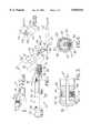
- FIG. 1is a perspective view of an embodiment of an orthopaedic stem inserter of the present invention, shown connected with a prosthetic implant in the form of a femoral component;
- FIG. 1Ais a fragmentary, side view in partial cross-section of the stem inserter of FIG. 1 showing an optional spring between the lever and the handle;
- FIG. 1Bis a perspective view of an optional insertion stop adaptor
- FIG. 2is a fragmentary, side sectional view of the stem inserter of FIG. 1, with the quick release lever depressed;
- FIG. 3is a fragmentary, side sectional view of the rotating knob at the end of the handle of the stem inserter of FIG. 1;
- FIG. 4is a sectional view of the rotating knob, taken along line 4--4 in FIG. 3;
- FIG. 5is a fragmentary, sectional view of the body, taken along line 5--5 in FIG. 2, with a fragmentary portion of the femoral component positioned in the fixed jaw;
- FIG. 6is a side view of another embodiment of an orthopaedic stem inserter of the present invention, with the quick release lever in a non-depressed position;
- FIG. 7is a side view of the stem inserter of FIG. 6, with the quick release lever in a depressed position;
- FIG. 8is a sectional view of the second gear and associated ratchet device, taken along line 8--8 in FIG. 7.
- Stem inserter 10may be connected with a prosthetic implant in the form of a femoral component 12.
- Stem inserter 10generally includes a handle 14, body 52 and quick release lever 18.
- Femoral component 12includes a stem 20 which may be inserted into a prepared opening in a femur (not shown).
- a femoral head 22is connected with a neck 24 of femoral component 12.
- a recessed area 26is disposed between neck 24 and stem 20, on each side of femoral component 12 (FIGS. 1 and 5), which creates a shoulder 23 at the top of each recessed area 26.
- Handle 14includes a housing 28, a rotating knob 30 and an elongate element 32.
- Rotating knob 30is connected to a first end 34 of housing 28.
- elongate element 32is in the form of a cylindrical rod.
- Elongate element 32passes through first end 34 of housing 28 and is rigidly connected with rotating knob 30.
- Elongate element 32is disposed within and extends through housing 28 to a second end 36, generally opposite from first end 34.
- Elongate element 32has a longitudinal axis which is substantially coincident with the longitudinal axis of cylindrical housing 28, both of which are commonly referenced as axis 38 in FIGS. 1 and 3.
- longitudinal axis 38 of elongate element 32 and housing 28is disposed substantially parallel to the longitudinal axis 40 associated with stem 20. This parallel relationship between housing 28 and stem 20 allows femoral component 12 to be more easily positioned relative to a prepared opening in a bone (not shown).
- a first ratchet deviceallows rotating knob 30 to be rotated in one direction about the longitudinal axis 38 of housing 28, while preventing rotation of knob 30 in an opposing direction about longitudinal axis 38.
- handle 28includes an opening 42 which is formed in first end 34.
- a beveled ratchet tooth 44is disposed within opening 42, and is biased in a direction out of opening 42 via a compression spring 46.
- Ratchet tooth 44engages one of a plurality of internal teeth 48 formed at the interior diameter of knob 30.
- Knob 30can thus rotate in one direction relative to first end 34, as indicated by directional arrow 50.
- ratchet tooth 44prevents rotation of knob 30 relative to first end 34 in a rotational direction which is opposite to arrow 50.
- Body 52which carries a pair of jaws 54 and 56 which are used for gripping femoral component 12.
- Movable jaw 54is movable in opposing directions toward and away from fixed jaw 56, as indicated by double headed arrow 57. The opposing directions indicated by arrow 57 are transverse to the longitudinal axis 38 of elongate element 32.
- the movable jaw 54is movable in opposing directions 57 which are disposed at an acute angle ⁇ relative to longitudinal axis 38.
- This angle ⁇preferable corresponds to the angle ⁇ ' between axis 40 of stem 20 and the longitudinal axis 25 of the neck 24.
- angle ⁇ and ⁇ 'are preferably substantially the same.
- Cup 58is carried by movable jaw 54; and an elastomeric pad 60 is carried by fixed jaw 56.
- Cup 58includes a recessed surface 62 which engages the top of femoral head 22.
- Recessed surface 62may be concave or conical or any other suitable shape.
- surface 62could be shaped to engage the femoral neck 24, if it is desired to grip the femoral component 12 without the head 22 attached.
- Pad 60has a generally U-shaped configuration, with each leg engaging a corresponding recessed area 26 on femoral component 12 (FIGS. 1 and 5).
- Body 52has a generally cylindrical shape in the embodiment shown in FIGS. 1-5.
- a cutout 64(FIGS. 2 and 5) in body 52 allows movable jaw 54 to move in opposing directions 57 relative to body 52.
- Movable jaw 54includes a rack 66 having a plurality of teeth 68.
- Rack 66is slidable within the cylindrical opening formed in body 52, and is biased in a direction out of the opening formed in body 52 by a compression spring 70.
- An interconnecting deviceinterconnects elongate element 32 with movable jaw 54 at the second end 36 of housing 28.
- the interconnecting deviceeffects movement of movable jaw 54 upon rotation of knob 30 at first end 34 of housing 28.
- the interconnecting deviceincludes geared rack 66 of movable jaw 54, a first gear 72 connected with rack 66 and a second gear 74 connected with elongate element 32.
- First gear 72is connected to a pinion gear 78 via set screw 76 (FIG. 2).
- Pinion gear 78in turn enmeshes with rack 66, and thereby connects first gear 72 with rack 66.
- Second gear 74is carried by elongate element 32, and is slidable along a portion of the length of elongate element 32.
- second gear 74has a substantially square opening formed therein which is slightly larger than an end 80 of elongate element 32 having a corresponding square cross section.
- elongate element 32has a circular cross-section throughout the majority of its length except for end portion 80 which has a square cross-section.
- End portion 80also is slightly reduced in width compared to the remainder of elongate portion 32.
- Second gear 74is movable between a first position which is enmeshed with first gear 72 (FIG. 1), and a second position which is demeshed with first gear 72 (FIG. 2).
- a collar 82is attached to elongate element 32 using, e.g., a set screw, and provides a stop surface facing second gear 74.
- a compression spring 84is interposed between second gear 74 and collar 82, and biases second gear 74 toward first gear 72.
- First and second gears 72 and 74are bevel gears which accommodate the angular relationship of longitudinal axis 38 of handle 14 to body 52 (and thus to the opposing directions 57 of movable jaw 54).
- Quick release lever 18is pivotally attached to handle 14 using a pivot pin 86 located within an interior of housing 28 at second end 36.
- Quick release lever 18extends through a slot 88 formed in housing 28 which allows lever 18 to be pivoted between the positions shown in FIGS. 1 and 2.
- compression spring 84biases second gear 74 into enmeshed engagement with first gear 72.
- the end of quick release lever 18is thus disposed a distance away from housing 28, as shown in FIG. 1.
- lever 18pivots about pivot pin 86 such that the end of lever 18 is disposed closely adjacent to or against housing 28.
- An engaging portion 92 on quick release lever 18engages an annular groove cut around the periphery of second gear 74. Moving the end of lever 18 toward housing 28 as indicated by arrow 90 in turn causes engaging portion 92 to move second gear 74 away from first gear 72 and thereby demesh second gear 74 and first gear 72.
- recessed area 26 of femoral component 12is slid into engagement with fixed jaw 56 such that U-shaped elastomeric pad 60 is engaged with the shoulder 23 of each respective recessed area 26.
- Knob 30is then rotated, which in turn rotates second gear 74 via the interconnection with elongate element 32. Second gear 74 in turn rotates first gear 72 and pinion gear 78. Rotation of pinion gear 78 causes translational movement of rack 66, thereby causing movable jaw 54 and elastomeric cup 58 to move toward femoral head 22.
- Knob 30is rotated until cup 58 firmly engages the top of femoral head 22.
- Femoral component 12can then be positioned relative to and inserted within a prepared opening in a femur.
- quick release lever 18is moved toward housing 28, as indicated by arrow 90. This causes second gear 74 to move away from and demesh with first gear 72, thereby allowing compression spring 70 to bias rack 66 and movable jaw 54 away from femoral head 22.
- Stem inserter 10may then be detached from femoral component 12 by simply sliding fixed jaw 56 out of engagement with recessed areas 26 on femoral component 12.
- FIG. 1Ashows an optional compression spring 6 which may be utilized between lever 18 and handle 14. This helps the gears 72, 74 from being accidently disengaged during impaction of inserter 10 upon positioning of femoral component 12.
- Compression spring 6is positioned about pin 8 which is fixed to lever 18 and extends through opening 4 in handle 14. Alternatively, the user can place a finger(s) under lever 18 while impacting the instrument to help prevent lever 18 from being permaturely depressed.
- FIG. 1Bshows an optional insertion stop adaptor 150 which selectively fits over fixed jaw 56 of inserter 10.
- the adaptor 150includes a wall 152 with two side arms 154.
- a window 156is provided in the upper portion of wall 152 to receive U-shaped fixed jaw 56 and pad 60 therethrough.
- Adaptor 150is designed so that the distal surface 158 of arms 154 contacts the calcar bone of the femur upon insertion of the femoral component 12 into the femur, when the femoral component 12 does not include a collar or does not include a collar large enough to contact the calcar bone upon insertion, e.g. as with a minimized collar.
- the distal surface 158is designed to align with the level of the cut calcar bone or the bottom of an extending minimized collar, such as 160 on femoral component 12.
- Various sizes of adaptors 150may be provided for varying sizes of stems.
- Stem inserter 100includes many components which are configured similar to the components of stem inserter 10 shown in FIGS. 1-5.
- stem inserter 100includes a handle 102, body 104 and quick release lever 108.
- stem inserter 100includes a knob 110, elongate element 112, first ratchet device 114, collar 116, compression spring 118, second gear 120, first gear 122, movable jaw 124, fixed jaw 126, elastomeric cup 128 and elastomeric pad 130, similar to the respectively named parts making up stem inserter 10 described above.
- stem inserter 100includes a quick release lever 108 which is pivotally attached via a pivot pin 132 at a location which is disposed outside of the housing of handle 102.
- body 104 of stem inserter 100is formed with a substantially square cross section, rather than a circular cross section as defined by body 52 of stem inserter 10.
- stem inserter 100has a circular cross-section throughout its length, rather than having a square cross-section portion as with end portion 80 of elongated element 32 of stem inserter 10.
- Stem inserter 100also includes a second ratchet device which allows movable jaw 124 to be moved in a direction toward fixed jaw 126 upon application of an external force to movable jaw 124 in a direction toward fixed jaw 126, via jaw extension 125, as indicated by arrow 134 (FIG. 7).
- the second ratchet devicealso prevents movement of movable jaw 124 in a direction away from fixed jaw 126 upon application of an external force to movable jaw 124 in a direction away from fixed jaw 126.
- elongate element 112includes an opening 136 which extends partially therein.
- a ratchet tooth 138is slidably disposed within opening 136, and biased in a direction out of opening 136 by a compression spring 140.
- Second gear 120includes a plurality of interior teeth 142 formed at the inside diameter thereof.
- Ratchet tooth 138 and interior teeth 142allow second gear 120 to move in a single rotational direction relative to elongate element 112 (indicated by arrow 144), while preventing relative rotational movement between ratchet tooth 138 and interior teeth 142 in a direction opposite to arrow 144.
- knob 110is rotated in a direction such that elongate element 112 rotates in the direction of arrow 144, no relative rotational movement occurs between ratchet tooth 138 and second gear 120, thus rotating second gear 120.
- movable jaw 124when an external force is applied to the end of movable jaw 124, as indicated by arrow 134, the rack associated with movable jaw 134 drives first gear 122 and second gear 120 in the direction of arrow 144, thereby allowing relative movement between second gear 120 and elongate element 112.
- movable jaw 124may be quickly moved into contact with the top of femoral head 22 by pushing movable jaw toward fixed jaw 126.
- the ratcheting rotational movement between ratchet tooth 138 and second gear 120allows movable jaw 124 to be relatively easily translated toward fixed jaw 126.
- stem inserter 100With the exception of the second ratchet device defined in part by ratchet tooth 138 and second gear 120 allowing sliding movement of movable jaw 124 toward fixed jaw 126 upon application of an external force to movable jaw 124, the operation of stem inserter 100 is essentially the same as the operation of stem inserter 10 described above. Accordingly, the operation of stem inserter 100 is not described in further detail.
- stem inserters 10 and 100may be made by any suitable manufacturing methods and of any suitable materials.
- the majority of the components of the inserter instrumentare made of a suitable metal material, such as stainless steel, except for the cup 58, 128, the pad 60, 130, and the adaptor 150, which are preferably made out of a suitable plastic material.
Landscapes
- Health & Medical Sciences (AREA)
- Transplantation (AREA)
- Orthopedic Medicine & Surgery (AREA)
- Heart & Thoracic Surgery (AREA)
- Cardiology (AREA)
- Oral & Maxillofacial Surgery (AREA)
- Engineering & Computer Science (AREA)
- Biomedical Technology (AREA)
- Physical Education & Sports Medicine (AREA)
- Vascular Medicine (AREA)
- Life Sciences & Earth Sciences (AREA)
- Animal Behavior & Ethology (AREA)
- General Health & Medical Sciences (AREA)
- Public Health (AREA)
- Veterinary Medicine (AREA)
- Prostheses (AREA)
Abstract
Description
Claims (21)
Priority Applications (1)
| Application Number | Priority Date | Filing Date | Title |
|---|---|---|---|
| US08/927,715US5849015A (en) | 1997-09-11 | 1997-09-11 | Orthopaedic stem inserter with quick release lever and ratchet |
Applications Claiming Priority (1)
| Application Number | Priority Date | Filing Date | Title |
|---|---|---|---|
| US08/927,715US5849015A (en) | 1997-09-11 | 1997-09-11 | Orthopaedic stem inserter with quick release lever and ratchet |
Publications (1)
| Publication Number | Publication Date |
|---|---|
| US5849015Atrue US5849015A (en) | 1998-12-15 |
Family
ID=25455139
Family Applications (1)
| Application Number | Title | Priority Date | Filing Date |
|---|---|---|---|
| US08/927,715Expired - Fee RelatedUS5849015A (en) | 1997-09-11 | 1997-09-11 | Orthopaedic stem inserter with quick release lever and ratchet |
Country Status (1)
| Country | Link |
|---|---|
| US (1) | US5849015A (en) |
Cited By (110)
| Publication number | Priority date | Publication date | Assignee | Title |
|---|---|---|---|---|
| US6110179A (en)* | 1998-03-02 | 2000-08-29 | Benoist Girard Sas | Prosthesis inserter |
| US6174335B1 (en)* | 1996-12-23 | 2001-01-16 | Johnson & Johnson Professional, Inc. | Alignment guide for slotted prosthetic stem |
| US6626913B1 (en) | 1999-03-03 | 2003-09-30 | Smith & Nephew, Inc. | Methods, systems, and instruments for inserting prosthetic implants |
| US20030208256A1 (en)* | 2002-05-03 | 2003-11-06 | Dimatteo Kristian | Hypotube endoluminal device |
| US20040010262A1 (en)* | 2002-07-12 | 2004-01-15 | Parkinson Fred W. | Tool for gripping and orthopedic implant |
| US20040122437A1 (en)* | 2002-12-20 | 2004-06-24 | Dwyer Kimberly A. | Alignment device for modular implants and method |
| US20060200162A1 (en)* | 2005-02-21 | 2006-09-07 | Zimmer Technology, Inc. | Total knee arthroplasty instruments |
| US20060247774A1 (en)* | 2005-04-29 | 2006-11-02 | Gil Carlos E | Spinal implant |
| US20060264897A1 (en)* | 2005-01-24 | 2006-11-23 | Neurosystec Corporation | Apparatus and method for delivering therapeutic and/or other agents to the inner ear and to other tissues |
| US20070078464A1 (en)* | 2005-09-30 | 2007-04-05 | Depuy Products, Inc. | Separator tool for a modular prosthesis |
| US20070173856A1 (en)* | 2006-01-25 | 2007-07-26 | Parker Brad A | Split thread orthopaedic implant impactor |
| US20070244566A1 (en)* | 2002-12-20 | 2007-10-18 | Depuy Products, Inc. | Trialing system and method for modular hip joint replacement system |
| US20070255237A1 (en)* | 2006-05-01 | 2007-11-01 | Neurosystec Corporation | Apparatus and method for delivery of therapeutic and other types of agents |
| US20080065002A1 (en)* | 2006-09-07 | 2008-03-13 | Neurosystec Corporation | Catheter for Localized Drug Delivery and/or Electrical Stimulation |
| US20080133023A1 (en)* | 2006-10-05 | 2008-06-05 | Zimmer Technology, Inc. | Provisional prosthetic component formed of multiple materials |
| US20080145439A1 (en)* | 2006-07-31 | 2008-06-19 | Neurosystec Corporation | Nanoparticle drug formulations |
| US20080152694A1 (en)* | 2006-07-20 | 2008-06-26 | Neurosystec Corporation | Devices, Systems and Methods for Ophthalmic Drug Delivery |
| US20080255565A1 (en)* | 2006-11-20 | 2008-10-16 | Fletcher Henry H | Broach handle for minimally invasive hip replacement surgery |
| US20080255574A1 (en)* | 2007-04-13 | 2008-10-16 | Zimmer Technology, Inc. | Instrument for insertion of prosthetic components |
| US20080269765A1 (en)* | 2007-04-27 | 2008-10-30 | Zimmer, Inc. | Instrument and method for implanting a prosthetic component |
| US20090099566A1 (en)* | 2007-10-10 | 2009-04-16 | Maness Megan A | Modular stem inserter |
| US20090112218A1 (en)* | 2007-10-31 | 2009-04-30 | Mccleary Larry G | Modular taper assembly device |
| US20090112219A1 (en)* | 2007-10-31 | 2009-04-30 | Daniels David W | Taper sleeve extractor |
| US20090112216A1 (en)* | 2007-10-30 | 2009-04-30 | Leisinger Steven R | Taper disengagement tool |
| US20090187251A1 (en)* | 2002-04-25 | 2009-07-23 | Zimmer Technology, Inc. | Modular bone implant, tools, and method |
| US20090307887A1 (en)* | 2003-06-25 | 2009-12-17 | Depuy Products, Inc. | Assembly tool for modular implants and associated method |
| US20100042215A1 (en)* | 2008-08-13 | 2010-02-18 | Stalcup Gregory C | Orthopaedic implant |
| US20100042214A1 (en)* | 2008-08-13 | 2010-02-18 | Nebosky Paul S | Drug delivery implants |
| US20100042213A1 (en)* | 2008-08-13 | 2010-02-18 | Nebosky Paul S | Drug delivery implants |
| US20100042226A1 (en)* | 2008-08-13 | 2010-02-18 | Nebosky Paul S | Orthopaedic implant with spatially varying porosity |
| US20100042167A1 (en)* | 2008-08-13 | 2010-02-18 | Nebosky Paul S | Orthopaedic screws |
| US7803148B2 (en) | 2006-06-09 | 2010-09-28 | Neurosystec Corporation | Flow-induced delivery from a drug mass |
| US7854737B2 (en) | 2002-12-20 | 2010-12-21 | Depuy Products, Inc. | Instrument and associated method of trailing for modular hip stems |
| US20110295067A1 (en)* | 2009-02-06 | 2011-12-01 | Biotech Innovations Ltda | Remote traction and guidance system for mini-invasive surgery |
| US8221432B2 (en) | 2010-03-05 | 2012-07-17 | Biomet Manufacturing Corp. | Method and apparatus for implanting a modular femoral hip |
| US8333807B2 (en) | 2010-03-05 | 2012-12-18 | Biomet Manufacturing Corp. | Method and apparatus for trialing and implanting a modular femoral hip |
| US8419799B2 (en) | 2003-06-25 | 2013-04-16 | Depuy Products, Inc. | Assembly tool for modular implants and associated method |
| US8419743B2 (en) | 2010-03-05 | 2013-04-16 | Biomet Manufacturing Corp. | Assembly tool for modular implants and associated method |
| US8460393B2 (en) | 2010-03-05 | 2013-06-11 | Biomet Manufacturing Corp. | Modular lateral hip augments |
| US8529569B2 (en) | 2010-03-05 | 2013-09-10 | Biomet Manufacturing, Llc | Method and apparatus for preparing a proximal femur |
| US8679130B2 (en) | 2010-03-05 | 2014-03-25 | Biomet Manufacturing, Llc | Guide assembly for lateral implants and associated methods |
| US8690951B2 (en) | 2005-11-18 | 2014-04-08 | Zimmer, Gmbh | Base platform for an artificial joint |
| US8764769B1 (en) | 2013-03-12 | 2014-07-01 | Levita Magnetics International Corp. | Grasper with magnetically-controlled positioning |
| US8998919B2 (en) | 2003-06-25 | 2015-04-07 | DePuy Synthes Products, LLC | Assembly tool for modular implants, kit and associated method |
| US9095452B2 (en) | 2010-09-01 | 2015-08-04 | DePuy Synthes Products, Inc. | Disassembly tool |
| US9101495B2 (en) | 2010-06-15 | 2015-08-11 | DePuy Synthes Products, Inc. | Spiral assembly tool |
| US9220611B2 (en) | 2011-07-12 | 2015-12-29 | Zimmer, Inc. | Femoral component instrument |
| US9320601B2 (en) | 2011-10-20 | 2016-04-26 | 206 Ortho, Inc. | Method and apparatus for treating bone fractures, and/or for fortifying and/or augmenting bone, including the provision and use of composite implants |
| US20160206433A1 (en)* | 2015-01-15 | 2016-07-21 | Justin D. Grostefon | Femoral stem including an anchor to facilitate assembly and implantation |
| US20160206430A1 (en)* | 2015-01-15 | 2016-07-21 | DePuy Synthes Products, Inc. | Assembly tool |
| US9504578B2 (en) | 2011-04-06 | 2016-11-29 | Depuy Synthes Products, Inc | Revision hip prosthesis having an implantable distal stem component |
| US9700431B2 (en) | 2008-08-13 | 2017-07-11 | Smed-Ta/Td, Llc | Orthopaedic implant with porous structural member |
| US20170196706A1 (en)* | 2016-01-11 | 2017-07-13 | Kambiz Behzadi | Assembler for modular prosthesis |
| US20170325972A1 (en)* | 2016-05-11 | 2017-11-16 | Zimmer, Inc. | Femoral head press instrument for prosthetic implant |
| US10010609B2 (en) | 2013-05-23 | 2018-07-03 | 206 Ortho, Inc. | Method and apparatus for treating bone fractures, and/or for fortifying and/or augmenting bone, including the provision and use of composite implants |
| US10010370B2 (en) | 2013-03-14 | 2018-07-03 | Levita Magnetics International Corp. | Magnetic control assemblies and systems therefor |
| US10441244B2 (en) | 2016-01-11 | 2019-10-15 | Kambiz Behzadi | Invasive sense measurement in prosthesis installation |
| US10463505B2 (en) | 2016-01-11 | 2019-11-05 | Kambiz Behzadi | Bone preparation apparatus and method |
| US10525168B2 (en) | 2010-10-20 | 2020-01-07 | 206 Ortho, Inc. | Method and apparatus for treating bone fractures, and/or for fortifying and/or augmenting bone, including the provision and use of composite implants, and novel composite structures which may be used for medical and non-medical applications |
| US10525169B2 (en) | 2010-10-20 | 2020-01-07 | 206 Ortho, Inc. | Method and apparatus for treating bone fractures, and/or for fortifying and/or augmenting bone, including the provision and use of composite implants, and novel composite structures which may be used for medical and non-medical applications |
| US10537348B2 (en) | 2014-01-21 | 2020-01-21 | Levita Magnetics International Corp. | Laparoscopic graspers and systems therefor |
| US10842645B2 (en) | 2008-08-13 | 2020-11-24 | Smed-Ta/Td, Llc | Orthopaedic implant with porous structural member |
| US10849766B2 (en) | 2016-01-11 | 2020-12-01 | Kambiz Behzadi | Implant evaluation in prosthesis installation |
| US10857261B2 (en) | 2010-10-20 | 2020-12-08 | 206 Ortho, Inc. | Implantable polymer for bone and vascular lesions |
| US10888436B2 (en) | 2017-02-01 | 2021-01-12 | Zimmer, Inc. | Tibial tray impactor |
| US10898192B2 (en) | 2017-06-15 | 2021-01-26 | Roberto Tapia Espriu | Adjustable pressure surgical clamp with releasable or integrated remote manipulator for laparoscopies |
| US10905456B2 (en) | 2016-01-11 | 2021-02-02 | Kambiz Behzadi | Bone preparation apparatus and method |
| US10905511B2 (en) | 2015-04-13 | 2021-02-02 | Levita Magnetics International Corp. | Grasper with magnetically-controlled positioning |
| US11020137B2 (en) | 2017-03-20 | 2021-06-01 | Levita Magnetics International Corp. | Directable traction systems and methods |
| US11026809B2 (en) | 2016-01-11 | 2021-06-08 | Kambiz Behzadi | Prosthesis installation and assembly |
| US11058796B2 (en) | 2010-10-20 | 2021-07-13 | 206 Ortho, Inc. | Method and apparatus for treating bone fractures, and/or for fortifying and/or augmenting bone, including the provision and use of composite implants, and novel composite structures which may be used for medical and non-medical applications |
| US20210212841A1 (en)* | 2020-01-14 | 2021-07-15 | Shukla Medical | Surgical extractor |
| US11109802B2 (en) | 2016-01-11 | 2021-09-07 | Kambiz Behzadi | Invasive sense measurement in prosthesis installation and bone preparation |
| USD938590S1 (en) | 2019-10-01 | 2021-12-14 | Howmedica Osteonics Corp. | Humeral implant |
| US11207109B2 (en) | 2010-10-20 | 2021-12-28 | 206 Ortho, Inc. | Method and apparatus for treating bone fractures, and/or for fortifying and/or augmenting bone, including the provision and use of composite implants, and novel composite structures which may be used for medical and non-medical applications |
| US11207197B2 (en) | 2019-08-01 | 2021-12-28 | DePuy Synthes Products, Inc. | Orthopaedic surgical instrument for total hip arthroplasty and associated orthopaedic surgical method of use |
| US11234840B2 (en) | 2016-01-11 | 2022-02-01 | Kambiz Behzadi | Bone preparation apparatus and method |
| US11241248B2 (en) | 2016-01-11 | 2022-02-08 | Kambiz Behzadi | Bone preparation apparatus and method |
| AU2020204546B2 (en)* | 2012-10-29 | 2022-03-03 | Stryker European Operations Limited | System for reverse shoulder implants |
| US11291483B2 (en) | 2010-10-20 | 2022-04-05 | 206 Ortho, Inc. | Method and apparatus for treating bone fractures, and/or for fortifying and/or augmenting bone, including the provision and use of composite implants |
| US11291426B2 (en) | 2016-01-11 | 2022-04-05 | Kambiz Behzadi | Quantitative assessment of implant bone preparation |
| US11298102B2 (en) | 2016-01-11 | 2022-04-12 | Kambiz Behzadi | Quantitative assessment of prosthesis press-fit fixation |
| US11331069B2 (en) | 2016-01-11 | 2022-05-17 | Kambiz Behzadi | Invasive sense measurement in prosthesis installation |
| US11375975B2 (en) | 2016-01-11 | 2022-07-05 | Kambiz Behzadi | Quantitative assessment of implant installation |
| US20220233322A1 (en)* | 2019-10-01 | 2022-07-28 | Howmedica Osteonics Corp. | Shoulder prosthesis components and assemblies |
| US11399946B2 (en) | 2016-01-11 | 2022-08-02 | Kambiz Behzadi | Prosthesis installation and assembly |
| US11413026B2 (en) | 2007-11-26 | 2022-08-16 | Attractive Surgical, Llc | Magnaretractor system and method |
| US11432933B2 (en) | 2014-01-24 | 2022-09-06 | Howmedica Osteonics Corp. | Humeral implant anchor system |
| US11458028B2 (en) | 2016-01-11 | 2022-10-04 | Kambiz Behzadi | Prosthesis installation and assembly |
| US11471291B2 (en) | 2014-12-10 | 2022-10-18 | Tornier Sas | Convertible stem/fracture stem |
| US11484627B2 (en) | 2010-10-20 | 2022-11-01 | 206 Ortho, Inc. | Method and apparatus for treating bone fractures, and/or for fortifying and/or augmenting bone, including the provision and use of composite implants, and novel composite structures which may be used for medical and non-medical applications |
| US11534314B2 (en) | 2016-01-11 | 2022-12-27 | Kambiz Behzadi | Quantitative assessment of prosthesis press-fit fixation |
| US11583354B2 (en) | 2015-04-13 | 2023-02-21 | Levita Magnetics International Corp. | Retractor systems, devices, and methods for use |
| WO2023086371A1 (en)* | 2021-11-11 | 2023-05-19 | Encore Medical, L.P. (D/B/A Djo Surgical) | Device for assembling implant systems |
| US11660200B2 (en) | 2016-03-25 | 2023-05-30 | Howmedica Osteonics Corp. | Stemless shoulder implant with fixation components |
| US11679006B2 (en) | 2011-10-31 | 2023-06-20 | Tornier Orthopedics Ireland, Ltd. | Systems for shoulder prostheses |
| US11751807B2 (en) | 2016-01-11 | 2023-09-12 | Kambiz Behzadi | Invasive sense measurement in prosthesis installation and bone preparation |
| US11766335B2 (en) | 2016-07-28 | 2023-09-26 | Howmedica Osteonics Corp. | Stemless prosthesis anchor component |
| US11890201B2 (en) | 2018-01-31 | 2024-02-06 | Tornier | Prosthesis for a fractured long bone |
| US11969336B2 (en) | 2018-10-08 | 2024-04-30 | Kambiz Behzadi | Connective tissue grafting |
| US11974925B2 (en) | 2017-09-25 | 2024-05-07 | Howmedica Osteonics Corp. | Patient specific stemless prosthesis anchor components |
| US12023253B2 (en) | 2014-01-24 | 2024-07-02 | Howmedica Osteonics Corp. | Humeral implant anchor system |
| US12109120B2 (en) | 2016-04-19 | 2024-10-08 | Stryker European Operations Limited | Pre-operatively planned humeral implant and planning method |
| US12167966B2 (en) | 2018-10-02 | 2024-12-17 | Howmedica Osteonics Corp. | Shoulder prosthesis components and assemblies |
| US12186207B2 (en) | 2021-04-12 | 2025-01-07 | Smith & Nephew, Inc. | Orthopedic instrument for inserting a femoral stem |
| US12193951B2 (en) | 2016-01-11 | 2025-01-14 | Kambiz Behzadi | Quantitative assessment of prosthesis press-fit fixation |
| US12208021B2 (en) | 2018-10-04 | 2025-01-28 | Depuy Ireland Unlimited Company | Prosthesis extraction system |
| US12262971B2 (en) | 2016-01-08 | 2025-04-01 | Levita Magnetics International Corp. | One-operator surgical system and methods of use |
| US12414857B2 (en) | 2015-08-19 | 2025-09-16 | Depuy Ireland Unlimited Company | Alignment guide |
| US12433754B2 (en) | 2017-12-11 | 2025-10-07 | Howmedica Osteonics Corp. | Method of use for stemless prosthesis anchor components |
Citations (14)
| Publication number | Priority date | Publication date | Assignee | Title |
|---|---|---|---|---|
| US3857389A (en)* | 1973-06-06 | 1974-12-31 | H Amstutz | Prosthesis holder |
| US4676798A (en)* | 1984-09-12 | 1987-06-30 | Joint Medical Products Corporation | Socket bearing assembly for a constrained ball and socket joint |
| US4686971A (en)* | 1984-11-19 | 1987-08-18 | Harris William H | Method and apparatus for extraction of prostheses |
| EP0207873B1 (en)* | 1985-06-24 | 1989-12-20 | Equipement Medical Et Chirurgical De L'ouest | Prosthesis holder |
| EP0408109A1 (en)* | 1989-07-10 | 1991-01-16 | Biotecnic Societe Anonyme | Device to assist the implantation, and allow the removel of, a hip prosthesis shaft |
| US4993410A (en)* | 1989-05-01 | 1991-02-19 | Kimsey Timothy P | Prosthetic removal device |
| US5064427A (en)* | 1991-05-14 | 1991-11-12 | Intermedics Orthopedics, Inc. | Apparatus for inserting and withdrawing humeral prosthesis |
| US5133765A (en)* | 1988-12-07 | 1992-07-28 | Fabrique D'implants Et D'instruments Chrirugicaux | Unit to fit a prosthesis component |
| WO1994005211A1 (en)* | 1992-09-09 | 1994-03-17 | Depuy Inc. | Bone cutting apparatus and method |
| US5391170A (en)* | 1991-12-13 | 1995-02-21 | David A. McGuire | Angled surgical screw driver and methods of arthroscopic ligament reconstruction |
| US5443471A (en)* | 1993-02-16 | 1995-08-22 | Howmedica, Inc. | Quick release handle assembly |
| US5476466A (en)* | 1993-07-20 | 1995-12-19 | Zimmer, Inc. | Orthopaedic positioning instrument |
| US5499986A (en)* | 1994-01-07 | 1996-03-19 | Smith & Nephew Richards Inc. | Quick release handle apparatus for removing and inserting intramedullary nails |
| US5514136A (en)* | 1994-09-06 | 1996-05-07 | Wright Medical Technology, Inc. | Surgical instrument for driving and rotating a long bone prosthesis |
- 1997
- 1997-09-11USUS08/927,715patent/US5849015A/ennot_activeExpired - Fee Related
Patent Citations (14)
| Publication number | Priority date | Publication date | Assignee | Title |
|---|---|---|---|---|
| US3857389A (en)* | 1973-06-06 | 1974-12-31 | H Amstutz | Prosthesis holder |
| US4676798A (en)* | 1984-09-12 | 1987-06-30 | Joint Medical Products Corporation | Socket bearing assembly for a constrained ball and socket joint |
| US4686971A (en)* | 1984-11-19 | 1987-08-18 | Harris William H | Method and apparatus for extraction of prostheses |
| EP0207873B1 (en)* | 1985-06-24 | 1989-12-20 | Equipement Medical Et Chirurgical De L'ouest | Prosthesis holder |
| US5133765A (en)* | 1988-12-07 | 1992-07-28 | Fabrique D'implants Et D'instruments Chrirugicaux | Unit to fit a prosthesis component |
| US4993410A (en)* | 1989-05-01 | 1991-02-19 | Kimsey Timothy P | Prosthetic removal device |
| EP0408109A1 (en)* | 1989-07-10 | 1991-01-16 | Biotecnic Societe Anonyme | Device to assist the implantation, and allow the removel of, a hip prosthesis shaft |
| US5064427A (en)* | 1991-05-14 | 1991-11-12 | Intermedics Orthopedics, Inc. | Apparatus for inserting and withdrawing humeral prosthesis |
| US5391170A (en)* | 1991-12-13 | 1995-02-21 | David A. McGuire | Angled surgical screw driver and methods of arthroscopic ligament reconstruction |
| WO1994005211A1 (en)* | 1992-09-09 | 1994-03-17 | Depuy Inc. | Bone cutting apparatus and method |
| US5443471A (en)* | 1993-02-16 | 1995-08-22 | Howmedica, Inc. | Quick release handle assembly |
| US5476466A (en)* | 1993-07-20 | 1995-12-19 | Zimmer, Inc. | Orthopaedic positioning instrument |
| US5499986A (en)* | 1994-01-07 | 1996-03-19 | Smith & Nephew Richards Inc. | Quick release handle apparatus for removing and inserting intramedullary nails |
| US5514136A (en)* | 1994-09-06 | 1996-05-07 | Wright Medical Technology, Inc. | Surgical instrument for driving and rotating a long bone prosthesis |
Non-Patent Citations (16)
| Title |
|---|
| Linvatec Concept Arthroscopy Paramax Angled Driver catalog p. 79 1992.* |
| Linvatec Concept Arthroscopy--Paramax™ Angled Driver-catalog p. 79-1992. |
| Osteonics C Taper Head Dissassembly Head Disassembly Instrument 1992.* |
| Osteonics-C-Taper Head Dissassembly--Head Disassembly Instrument-1992. |
| Smith & Nephew Richards Modular Hip System Femoral Head Removal Device 1991.* |
| Smith & Nephew Richards--Modular Hip System-Femoral Head Removal Device-1991. |
| Zimmer, Inc. Femoral Pros. Holder and Femoral Neck Punch catalog pp. A13, A41 Jun. 1978.* |
| Zimmer, Inc. Fenlin Total Shoulder brochure c1993 Literature No. 97 4065 101, Rev. 3.* |
| Zimmer, Inc. Humeral Stem Driver Fenlin Shoulder Surgical Technique, p. 2 1989.* |
| Zimmer, Inc. Humeral Stem Inserter Fenlin Shoulder Surgical Technique, p. 3 c1994 Lit No. 97 4065 102 Rev 2.* |
| Zimmer, Inc. Inserting and Disassembly Instruments Zimmer catalog p. A87 1991.* |
| Zimmer, Inc.--Femoral Pros. Holder and Femoral Neck Punch-catalog pp. A13, A41-Jun. 1978. |
| Zimmer, Inc.--Fenlin Total Shoulder brochure-c1993-Literature No. 97-4065-101, Rev. 3. |
| Zimmer, Inc.--Humeral Stem Driver-Fenlin Shoulder Surgical Technique, p. 2-1989. |
| Zimmer, Inc.--Humeral Stem Inserter--Fenlin Shoulder Surgical Technique, p. 3-c1994-Lit No. 97-4065-102 Rev 2. |
| Zimmer, Inc.--Inserting and Disassembly Instruments-Zimmer catalog p. A87-1991. |
Cited By (211)
| Publication number | Priority date | Publication date | Assignee | Title |
|---|---|---|---|---|
| US6174335B1 (en)* | 1996-12-23 | 2001-01-16 | Johnson & Johnson Professional, Inc. | Alignment guide for slotted prosthetic stem |
| US6110179A (en)* | 1998-03-02 | 2000-08-29 | Benoist Girard Sas | Prosthesis inserter |
| US6626913B1 (en) | 1999-03-03 | 2003-09-30 | Smith & Nephew, Inc. | Methods, systems, and instruments for inserting prosthetic implants |
| US8075628B2 (en) | 2002-04-25 | 2011-12-13 | Zimmer, Inc. | Modular bone implant, tools, and method |
| US20090187251A1 (en)* | 2002-04-25 | 2009-07-23 | Zimmer Technology, Inc. | Modular bone implant, tools, and method |
| US7799086B2 (en) | 2002-04-25 | 2010-09-21 | Zimmer Technology, Inc. | Modular bone implant, tools, and method |
| US20030208256A1 (en)* | 2002-05-03 | 2003-11-06 | Dimatteo Kristian | Hypotube endoluminal device |
| US20040010262A1 (en)* | 2002-07-12 | 2004-01-15 | Parkinson Fred W. | Tool for gripping and orthopedic implant |
| US7037311B2 (en) | 2002-07-12 | 2006-05-02 | Zimmer Technology, Inc. | Tool for gripping an orthopedic implant |
| US7854737B2 (en) | 2002-12-20 | 2010-12-21 | Depuy Products, Inc. | Instrument and associated method of trailing for modular hip stems |
| US7794503B2 (en) | 2002-12-20 | 2010-09-14 | Depuy Products, Inc. | Trialing system and method for modular hip joint replacement system |
| US20040122437A1 (en)* | 2002-12-20 | 2004-06-24 | Dwyer Kimberly A. | Alignment device for modular implants and method |
| US8529578B2 (en) | 2002-12-20 | 2013-09-10 | DePuy Synthes Products, LLC | Instrument and associated method of trialing for modular hip stems |
| US20070244566A1 (en)* | 2002-12-20 | 2007-10-18 | Depuy Products, Inc. | Trialing system and method for modular hip joint replacement system |
| US7022141B2 (en)* | 2002-12-20 | 2006-04-04 | Depuy Products, Inc. | Alignment device for modular implants and method |
| US20100292806A1 (en)* | 2002-12-20 | 2010-11-18 | Depuy Products, Inc. | Trialing System and Method for Modular Hip Joint Replacement System |
| US20110046745A1 (en)* | 2002-12-20 | 2011-02-24 | Depuy Products, Inc. | Instrument and associated method of trialing for modular hip stems |
| US8998919B2 (en) | 2003-06-25 | 2015-04-07 | DePuy Synthes Products, LLC | Assembly tool for modular implants, kit and associated method |
| US8685036B2 (en) | 2003-06-25 | 2014-04-01 | Michael C. Jones | Assembly tool for modular implants and associated method |
| US8419799B2 (en) | 2003-06-25 | 2013-04-16 | Depuy Products, Inc. | Assembly tool for modular implants and associated method |
| US9381097B2 (en) | 2003-06-25 | 2016-07-05 | DePuy Synthes Products, Inc. | Assembly tool for modular implants, kit and associated method |
| US20090307887A1 (en)* | 2003-06-25 | 2009-12-17 | Depuy Products, Inc. | Assembly tool for modular implants and associated method |
| WO2006079055A3 (en)* | 2005-01-24 | 2009-04-16 | Neurosystec Corp | Apparatus and method for delivering therapeutic and/or other agents to the inner ear and to other tissues |
| US20060264897A1 (en)* | 2005-01-24 | 2006-11-23 | Neurosystec Corporation | Apparatus and method for delivering therapeutic and/or other agents to the inner ear and to other tissues |
| US20060200162A1 (en)* | 2005-02-21 | 2006-09-07 | Zimmer Technology, Inc. | Total knee arthroplasty instruments |
| US20060247774A1 (en)* | 2005-04-29 | 2006-11-02 | Gil Carlos E | Spinal implant |
| US8147547B2 (en) | 2005-04-29 | 2012-04-03 | Warsaw Orthopedic, Inc. | Spinal implant |
| US8152814B2 (en) | 2005-09-30 | 2012-04-10 | Depuy Products, Inc. | Separator tool for a modular prosthesis |
| US20070078464A1 (en)* | 2005-09-30 | 2007-04-05 | Depuy Products, Inc. | Separator tool for a modular prosthesis |
| US8690951B2 (en) | 2005-11-18 | 2014-04-08 | Zimmer, Gmbh | Base platform for an artificial joint |
| US20070173856A1 (en)* | 2006-01-25 | 2007-07-26 | Parker Brad A | Split thread orthopaedic implant impactor |
| US7621921B2 (en)* | 2006-01-25 | 2009-11-24 | Symmetry Medical, Inc | Split thread orthopaedic implant impactor |
| US20070255237A1 (en)* | 2006-05-01 | 2007-11-01 | Neurosystec Corporation | Apparatus and method for delivery of therapeutic and other types of agents |
| US8267905B2 (en) | 2006-05-01 | 2012-09-18 | Neurosystec Corporation | Apparatus and method for delivery of therapeutic and other types of agents |
| US20110071493A1 (en)* | 2006-06-09 | 2011-03-24 | Neurosystec Corporation | Flow-Induced Delivery from a Drug Mass |
| US8298176B2 (en) | 2006-06-09 | 2012-10-30 | Neurosystec Corporation | Flow-induced delivery from a drug mass |
| US7803148B2 (en) | 2006-06-09 | 2010-09-28 | Neurosystec Corporation | Flow-induced delivery from a drug mass |
| US20080152694A1 (en)* | 2006-07-20 | 2008-06-26 | Neurosystec Corporation | Devices, Systems and Methods for Ophthalmic Drug Delivery |
| US20080145439A1 (en)* | 2006-07-31 | 2008-06-19 | Neurosystec Corporation | Nanoparticle drug formulations |
| US20080065002A1 (en)* | 2006-09-07 | 2008-03-13 | Neurosystec Corporation | Catheter for Localized Drug Delivery and/or Electrical Stimulation |
| US20080133023A1 (en)* | 2006-10-05 | 2008-06-05 | Zimmer Technology, Inc. | Provisional prosthetic component formed of multiple materials |
| US20080255565A1 (en)* | 2006-11-20 | 2008-10-16 | Fletcher Henry H | Broach handle for minimally invasive hip replacement surgery |
| US20080255574A1 (en)* | 2007-04-13 | 2008-10-16 | Zimmer Technology, Inc. | Instrument for insertion of prosthetic components |
| US20080269765A1 (en)* | 2007-04-27 | 2008-10-30 | Zimmer, Inc. | Instrument and method for implanting a prosthetic component |
| US20090099566A1 (en)* | 2007-10-10 | 2009-04-16 | Maness Megan A | Modular stem inserter |
| US9717545B2 (en) | 2007-10-30 | 2017-08-01 | DePuy Synthes Products, Inc. | Taper disengagement tool |
| US20090112216A1 (en)* | 2007-10-30 | 2009-04-30 | Leisinger Steven R | Taper disengagement tool |
| US8556912B2 (en) | 2007-10-30 | 2013-10-15 | DePuy Synthes Products, LLC | Taper disengagement tool |
| US20090112218A1 (en)* | 2007-10-31 | 2009-04-30 | Mccleary Larry G | Modular taper assembly device |
| US20090112219A1 (en)* | 2007-10-31 | 2009-04-30 | Daniels David W | Taper sleeve extractor |
| US9119601B2 (en) | 2007-10-31 | 2015-09-01 | DePuy Synthes Products, Inc. | Modular taper assembly device |
| US8518050B2 (en) | 2007-10-31 | 2013-08-27 | DePuy Synthes Products, LLC | Modular taper assembly device |
| US11413026B2 (en) | 2007-11-26 | 2022-08-16 | Attractive Surgical, Llc | Magnaretractor system and method |
| US11413025B2 (en) | 2007-11-26 | 2022-08-16 | Attractive Surgical, Llc | Magnaretractor system and method |
| US9561354B2 (en) | 2008-08-13 | 2017-02-07 | Smed-Ta/Td, Llc | Drug delivery implants |
| US20100042167A1 (en)* | 2008-08-13 | 2010-02-18 | Nebosky Paul S | Orthopaedic screws |
| US10349993B2 (en) | 2008-08-13 | 2019-07-16 | Smed-Ta/Td, Llc | Drug delivery implants |
| US9700431B2 (en) | 2008-08-13 | 2017-07-11 | Smed-Ta/Td, Llc | Orthopaedic implant with porous structural member |
| US20100042215A1 (en)* | 2008-08-13 | 2010-02-18 | Stalcup Gregory C | Orthopaedic implant |
| US10842645B2 (en) | 2008-08-13 | 2020-11-24 | Smed-Ta/Td, Llc | Orthopaedic implant with porous structural member |
| US20100042214A1 (en)* | 2008-08-13 | 2010-02-18 | Nebosky Paul S | Drug delivery implants |
| US9358056B2 (en) | 2008-08-13 | 2016-06-07 | Smed-Ta/Td, Llc | Orthopaedic implant |
| US20100042226A1 (en)* | 2008-08-13 | 2010-02-18 | Nebosky Paul S | Orthopaedic implant with spatially varying porosity |
| US20100042213A1 (en)* | 2008-08-13 | 2010-02-18 | Nebosky Paul S | Drug delivery implants |
| US10357298B2 (en) | 2008-08-13 | 2019-07-23 | Smed-Ta/Td, Llc | Drug delivery implants |
| US8475505B2 (en) | 2008-08-13 | 2013-07-02 | Smed-Ta/Td, Llc | Orthopaedic screws |
| US9616205B2 (en) | 2008-08-13 | 2017-04-11 | Smed-Ta/Td, Llc | Drug delivery implants |
| US8702767B2 (en) | 2008-08-13 | 2014-04-22 | Smed-Ta/Td, Llc | Orthopaedic Screws |
| US11426291B2 (en) | 2008-08-13 | 2022-08-30 | Smed-Ta/Td, Llc | Orthopaedic implant with porous structural member |
| US8790245B2 (en)* | 2009-02-06 | 2014-07-29 | Levita Magnetics International Corp. | Remote traction and guidance system for mini-invasive surgery |
| US9974546B2 (en) | 2009-02-06 | 2018-05-22 | Levita Magnetics International Corp. | Remote traction and guidance system for mini-invasive surgery |
| US20110295067A1 (en)* | 2009-02-06 | 2011-12-01 | Biotech Innovations Ltda | Remote traction and guidance system for mini-invasive surgery |
| US9844391B2 (en) | 2009-02-06 | 2017-12-19 | Levita Magnetics International Corp. | Remote traction and guidance system for mini-invasive surgery |
| US8876837B2 (en) | 2010-03-05 | 2014-11-04 | Biomet Manufacturing, Llc | Method and apparatus for implanting a modular femoral hip |
| US9615942B2 (en) | 2010-03-05 | 2017-04-11 | Biomet Manufacturing, Llc | Method and apparatus for trialing and implanting a modular femoral hip |
| US9339318B2 (en) | 2010-03-05 | 2016-05-17 | Biomet Manufacturing, Llc | Method and apparatus for preparing a proximal femur |
| US8460393B2 (en) | 2010-03-05 | 2013-06-11 | Biomet Manufacturing Corp. | Modular lateral hip augments |
| US9138273B2 (en) | 2010-03-05 | 2015-09-22 | Biomet Manufacturing, Llc | Guide assembly for lateral implants and associated methods |
| US8679130B2 (en) | 2010-03-05 | 2014-03-25 | Biomet Manufacturing, Llc | Guide assembly for lateral implants and associated methods |
| US8333807B2 (en) | 2010-03-05 | 2012-12-18 | Biomet Manufacturing Corp. | Method and apparatus for trialing and implanting a modular femoral hip |
| US10188520B2 (en) | 2010-03-05 | 2019-01-29 | Biomet Manufacturing, Llc | Modular lateral hip augments |
| US9314287B2 (en) | 2010-03-05 | 2016-04-19 | Biomet Manufacturing, Llc | Assembly tool for modular implant and associated method |
| US9510950B2 (en) | 2010-03-05 | 2016-12-06 | Biomet Manufacturing, Llc | Modular lateral hip auguments |
| US8221432B2 (en) | 2010-03-05 | 2012-07-17 | Biomet Manufacturing Corp. | Method and apparatus for implanting a modular femoral hip |
| US8529569B2 (en) | 2010-03-05 | 2013-09-10 | Biomet Manufacturing, Llc | Method and apparatus for preparing a proximal femur |
| US8906109B2 (en) | 2010-03-05 | 2014-12-09 | Biomet Manufacturing, Llc | Modular lateral hip augments |
| US8591518B2 (en) | 2010-03-05 | 2013-11-26 | Biomet Manufacturing, Llc | Method and apparatus for implanting a modular femoral hip |
| US8419743B2 (en) | 2010-03-05 | 2013-04-16 | Biomet Manufacturing Corp. | Assembly tool for modular implants and associated method |
| US10166118B2 (en) | 2010-06-15 | 2019-01-01 | DePuy Synthes Products, Inc. | Spiral assembly tool |
| US9101495B2 (en) | 2010-06-15 | 2015-08-11 | DePuy Synthes Products, Inc. | Spiral assembly tool |
| US10292837B2 (en) | 2010-09-01 | 2019-05-21 | Depuy Synthes Products Inc. | Disassembly tool |
| US9095452B2 (en) | 2010-09-01 | 2015-08-04 | DePuy Synthes Products, Inc. | Disassembly tool |
| US9867720B2 (en) | 2010-09-01 | 2018-01-16 | DePuy Synthes Products, Inc. | Disassembly tool |
| US11291483B2 (en) | 2010-10-20 | 2022-04-05 | 206 Ortho, Inc. | Method and apparatus for treating bone fractures, and/or for fortifying and/or augmenting bone, including the provision and use of composite implants |
| US10525168B2 (en) | 2010-10-20 | 2020-01-07 | 206 Ortho, Inc. | Method and apparatus for treating bone fractures, and/or for fortifying and/or augmenting bone, including the provision and use of composite implants, and novel composite structures which may be used for medical and non-medical applications |
| US10525169B2 (en) | 2010-10-20 | 2020-01-07 | 206 Ortho, Inc. | Method and apparatus for treating bone fractures, and/or for fortifying and/or augmenting bone, including the provision and use of composite implants, and novel composite structures which may be used for medical and non-medical applications |
| US10517654B2 (en) | 2010-10-20 | 2019-12-31 | 206 Ortho, Inc. | Method and apparatus for treating bone fractures, and/or for fortifying and/or augmenting bone, including the provision and use of composite implants |
| US10857261B2 (en) | 2010-10-20 | 2020-12-08 | 206 Ortho, Inc. | Implantable polymer for bone and vascular lesions |
| US11058796B2 (en) | 2010-10-20 | 2021-07-13 | 206 Ortho, Inc. | Method and apparatus for treating bone fractures, and/or for fortifying and/or augmenting bone, including the provision and use of composite implants, and novel composite structures which may be used for medical and non-medical applications |
| US11850323B2 (en) | 2010-10-20 | 2023-12-26 | 206 Ortho, Inc. | Implantable polymer for bone and vascular lesions |
| US11207109B2 (en) | 2010-10-20 | 2021-12-28 | 206 Ortho, Inc. | Method and apparatus for treating bone fractures, and/or for fortifying and/or augmenting bone, including the provision and use of composite implants, and novel composite structures which may be used for medical and non-medical applications |
| US11351261B2 (en) | 2010-10-20 | 2022-06-07 | 206 Ortho, Inc. | Method and apparatus for treating bone fractures, and/or for fortifying and/or augmenting bone, including the provision and use of composite implants |
| US10028776B2 (en) | 2010-10-20 | 2018-07-24 | 206 Ortho, Inc. | Method and apparatus for treating bone fractures, and/or for fortifying and/or augmenting bone, including the provision and use of composite implants |
| US11484627B2 (en) | 2010-10-20 | 2022-11-01 | 206 Ortho, Inc. | Method and apparatus for treating bone fractures, and/or for fortifying and/or augmenting bone, including the provision and use of composite implants, and novel composite structures which may be used for medical and non-medical applications |
| US10064725B2 (en) | 2011-04-06 | 2018-09-04 | DePuy Synthes Products, Inc. | Distal reamer for use during an orthopaedic surgical procedure to implant a revision hip prosthesis |
| US10772730B2 (en) | 2011-04-06 | 2020-09-15 | DePuy Synthes Products, Inc. | Finishing rasp and orthopaedic surgical procedure for using the same to implant a revision hip prosthesis |
| US10888427B2 (en) | 2011-04-06 | 2021-01-12 | DePuy Synthes Products, Inc. | Distal reamer for use during an orthopaedic surgical procedure to implant a revision hip prosthesis |
| US9737405B2 (en) | 2011-04-06 | 2017-08-22 | DePuy Synthes Products, Inc. | Orthopaedic surgical procedure for implanting a revision hip prosthesis |
| US10925739B2 (en) | 2011-04-06 | 2021-02-23 | DePuy Synthes Products, Inc. | Version-replicating instrument and orthopaedic surgical procedure for using the same to implant a revision hip prosthesis |
| US10603173B2 (en) | 2011-04-06 | 2020-03-31 | DePuy Synthes Products, Inc. | Orthopaedic surgical procedure for implanting a revision hip prosthesis |
| US10226345B2 (en) | 2011-04-06 | 2019-03-12 | DePuy Synthes Products, Inc. | Version-replicating instrument and orthopaedic surgical procedure for using the same to implant a revision hip prosthesis |
| US9949833B2 (en) | 2011-04-06 | 2018-04-24 | DePuy Synthes Products, Inc. | Finishing RASP and orthopaedic surgical procedure for using the same to implant a revision hip prosthesis |
| US9504578B2 (en) | 2011-04-06 | 2016-11-29 | Depuy Synthes Products, Inc | Revision hip prosthesis having an implantable distal stem component |
| US9597188B2 (en) | 2011-04-06 | 2017-03-21 | DePuy Synthes Products, Inc. | Version-replicating instrument and orthopaedic surgical procedure for using the same to implant a revision hip prosthesis |
| US9220611B2 (en) | 2011-07-12 | 2015-12-29 | Zimmer, Inc. | Femoral component instrument |
| US9901462B2 (en) | 2011-07-12 | 2018-02-27 | Zimmer, Inc. | Femoral component instrument |
| US9320601B2 (en) | 2011-10-20 | 2016-04-26 | 206 Ortho, Inc. | Method and apparatus for treating bone fractures, and/or for fortifying and/or augmenting bone, including the provision and use of composite implants |
| US11679006B2 (en) | 2011-10-31 | 2023-06-20 | Tornier Orthopedics Ireland, Ltd. | Systems for shoulder prostheses |
| AU2020204546B2 (en)* | 2012-10-29 | 2022-03-03 | Stryker European Operations Limited | System for reverse shoulder implants |
| US12064353B2 (en) | 2012-10-29 | 2024-08-20 | Stryker European Operations Limited | Systems for reverse shoulder implants |
| US10130381B2 (en) | 2013-03-12 | 2018-11-20 | Levita Magnetics International Corp. | Grasper with magnetically-controlled positioning |
| US11357525B2 (en) | 2013-03-12 | 2022-06-14 | Levita Magnetics International Corp. | Grasper with magnetically-controlled positioning |
| US12329402B2 (en) | 2013-03-12 | 2025-06-17 | Levita Magnetics International Corp. | Grasper with magnetically-controlled positioning |
| US8764769B1 (en) | 2013-03-12 | 2014-07-01 | Levita Magnetics International Corp. | Grasper with magnetically-controlled positioning |
| US9339285B2 (en) | 2013-03-12 | 2016-05-17 | Levita Magnetics International Corp. | Grasper with magnetically-controlled positioning |
| US10010370B2 (en) | 2013-03-14 | 2018-07-03 | Levita Magnetics International Corp. | Magnetic control assemblies and systems therefor |
| US10010609B2 (en) | 2013-05-23 | 2018-07-03 | 206 Ortho, Inc. | Method and apparatus for treating bone fractures, and/or for fortifying and/or augmenting bone, including the provision and use of composite implants |
| US11730476B2 (en) | 2014-01-21 | 2023-08-22 | Levita Magnetics International Corp. | Laparoscopic graspers and systems therefor |
| US12171433B2 (en) | 2014-01-21 | 2024-12-24 | Levita Magnetics International Corp. | Laparoscopic graspers and systems therefor |
| US10537348B2 (en) | 2014-01-21 | 2020-01-21 | Levita Magnetics International Corp. | Laparoscopic graspers and systems therefor |
| US11628067B2 (en) | 2014-01-24 | 2023-04-18 | Howmedica Osteonics Corp. | Humeral implant anchor system |
| US12023253B2 (en) | 2014-01-24 | 2024-07-02 | Howmedica Osteonics Corp. | Humeral implant anchor system |
| US11432933B2 (en) | 2014-01-24 | 2022-09-06 | Howmedica Osteonics Corp. | Humeral implant anchor system |
| US12343262B2 (en) | 2014-12-10 | 2025-07-01 | Tornier Sas | Convertible stem/fracture stem |
| US11471291B2 (en) | 2014-12-10 | 2022-10-18 | Tornier Sas | Convertible stem/fracture stem |
| CN107106308A (en)* | 2015-01-15 | 2017-08-29 | 德普伊新特斯产品公司 | Assembly Tool |
| CN107106301A (en)* | 2015-01-15 | 2017-08-29 | 德普伊新特斯产品公司 | Including the femoral stem for the anchor log for being conducive to assembling and being implanted into |
| US10085838B2 (en) | 2015-01-15 | 2018-10-02 | Depuy Ireland Unlimited Company | Assembly tool |
| US10022234B2 (en)* | 2015-01-15 | 2018-07-17 | Depuy Ireland Unlimited Company | Assembly tool |
| US20160206430A1 (en)* | 2015-01-15 | 2016-07-21 | DePuy Synthes Products, Inc. | Assembly tool |
| CN107106301B (en)* | 2015-01-15 | 2019-06-14 | 德普伊新特斯产品公司 | Femoral stem including anchors to facilitate assembly and implantation |
| US9937048B2 (en)* | 2015-01-15 | 2018-04-10 | Depuy Ireland Unlimited Company | Femoral stem including an anchor to facilitate assembly and implantation |
| US20160206433A1 (en)* | 2015-01-15 | 2016-07-21 | Justin D. Grostefon | Femoral stem including an anchor to facilitate assembly and implantation |
| JP2018505725A (en)* | 2015-01-15 | 2018-03-01 | デピュイ・シンセス・プロダクツ・インコーポレイテッド | Femoral stem including an anchor that facilitates assembly and implantation |
| US10368996B2 (en) | 2015-01-15 | 2019-08-06 | Depuy Ireland Unlimited Company | Assembly tool |
| US12357407B2 (en) | 2015-04-13 | 2025-07-15 | Levita Magnetics International Corp. | Grasper with magnetically-controlled positioning |
| US11751965B2 (en) | 2015-04-13 | 2023-09-12 | Levita Magnetics International Corp. | Grasper with magnetically-controlled positioning |
| US11583354B2 (en) | 2015-04-13 | 2023-02-21 | Levita Magnetics International Corp. | Retractor systems, devices, and methods for use |
| US10905511B2 (en) | 2015-04-13 | 2021-02-02 | Levita Magnetics International Corp. | Grasper with magnetically-controlled positioning |
| US12414857B2 (en) | 2015-08-19 | 2025-09-16 | Depuy Ireland Unlimited Company | Alignment guide |
| US12262971B2 (en) | 2016-01-08 | 2025-04-01 | Levita Magnetics International Corp. | One-operator surgical system and methods of use |
| US11896500B2 (en) | 2016-01-11 | 2024-02-13 | Kambiz Behzadi | Bone preparation apparatus and method |
| US11751807B2 (en) | 2016-01-11 | 2023-09-12 | Kambiz Behzadi | Invasive sense measurement in prosthesis installation and bone preparation |
| US11298102B2 (en) | 2016-01-11 | 2022-04-12 | Kambiz Behzadi | Quantitative assessment of prosthesis press-fit fixation |
| US11291426B2 (en) | 2016-01-11 | 2022-04-05 | Kambiz Behzadi | Quantitative assessment of implant bone preparation |
| US11375975B2 (en) | 2016-01-11 | 2022-07-05 | Kambiz Behzadi | Quantitative assessment of implant installation |
| US10660767B2 (en)* | 2016-01-11 | 2020-05-26 | Kambiz Behzadi | Assembler for modular prosthesis |
| US11399946B2 (en) | 2016-01-11 | 2022-08-02 | Kambiz Behzadi | Prosthesis installation and assembly |
| US11241248B2 (en) | 2016-01-11 | 2022-02-08 | Kambiz Behzadi | Bone preparation apparatus and method |
| US11234840B2 (en) | 2016-01-11 | 2022-02-01 | Kambiz Behzadi | Bone preparation apparatus and method |
| US12102446B2 (en) | 2016-01-11 | 2024-10-01 | Kambiz Behzadi | Invasive sense measurement in prosthesis installation and bone preparation |
| US10441244B2 (en) | 2016-01-11 | 2019-10-15 | Kambiz Behzadi | Invasive sense measurement in prosthesis installation |
| US11458028B2 (en) | 2016-01-11 | 2022-10-04 | Kambiz Behzadi | Prosthesis installation and assembly |
| US11191517B2 (en) | 2016-01-11 | 2021-12-07 | Kambiz Behzadi | Invasive sense measurement in prosthesis installation |
| US11109802B2 (en) | 2016-01-11 | 2021-09-07 | Kambiz Behzadi | Invasive sense measurement in prosthesis installation and bone preparation |
| US11534314B2 (en) | 2016-01-11 | 2022-12-27 | Kambiz Behzadi | Quantitative assessment of prosthesis press-fit fixation |
| US10463505B2 (en) | 2016-01-11 | 2019-11-05 | Kambiz Behzadi | Bone preparation apparatus and method |
| US11331069B2 (en) | 2016-01-11 | 2022-05-17 | Kambiz Behzadi | Invasive sense measurement in prosthesis installation |
| US20170196706A1 (en)* | 2016-01-11 | 2017-07-13 | Kambiz Behzadi | Assembler for modular prosthesis |
| US10849766B2 (en) | 2016-01-11 | 2020-12-01 | Kambiz Behzadi | Implant evaluation in prosthesis installation |
| US11974877B2 (en) | 2016-01-11 | 2024-05-07 | Kambiz Behzadi | Quantitative assessment of implant bone preparation |
| US10653533B2 (en)* | 2016-01-11 | 2020-05-19 | Kambiz Behzadi | Assembler for modular prosthesis |
| US11974876B2 (en) | 2016-01-11 | 2024-05-07 | Kambiz Behzadi | Quantitative assessment of prosthesis press-fit fixation |
| US11026809B2 (en) | 2016-01-11 | 2021-06-08 | Kambiz Behzadi | Prosthesis installation and assembly |
| US11717310B2 (en) | 2016-01-11 | 2023-08-08 | Kambiz Behzadi | Bone preparation apparatus and method |
| US11890196B2 (en) | 2016-01-11 | 2024-02-06 | Kambiz Behzadi | Prosthesis installation and assembly |
| US12193951B2 (en) | 2016-01-11 | 2025-01-14 | Kambiz Behzadi | Quantitative assessment of prosthesis press-fit fixation |
| US10912655B2 (en) | 2016-01-11 | 2021-02-09 | Kambiz Behzadi | Force sense measurement in prosthesis installation |
| US11883056B2 (en) | 2016-01-11 | 2024-01-30 | Kambiz Behzadi | Bone preparation apparatus and method |
| US11786207B2 (en) | 2016-01-11 | 2023-10-17 | Kambiz Behzadi | Invasive sense measurement in prosthesis installation |
| US10905456B2 (en) | 2016-01-11 | 2021-02-02 | Kambiz Behzadi | Bone preparation apparatus and method |
| US11660200B2 (en) | 2016-03-25 | 2023-05-30 | Howmedica Osteonics Corp. | Stemless shoulder implant with fixation components |
| US12109120B2 (en) | 2016-04-19 | 2024-10-08 | Stryker European Operations Limited | Pre-operatively planned humeral implant and planning method |
| US10722383B2 (en)* | 2016-05-11 | 2020-07-28 | Zimmer, Inc. | Femoral head press instrument for prosthetic implant |
| US20170325972A1 (en)* | 2016-05-11 | 2017-11-16 | Zimmer, Inc. | Femoral head press instrument for prosthetic implant |
| US12109121B2 (en) | 2016-07-28 | 2024-10-08 | Howmedica Osteonics Corp. | Stemless prosthesis anchor component |
| US11766335B2 (en) | 2016-07-28 | 2023-09-26 | Howmedica Osteonics Corp. | Stemless prosthesis anchor component |
| US10888436B2 (en) | 2017-02-01 | 2021-01-12 | Zimmer, Inc. | Tibial tray impactor |
| US11020137B2 (en) | 2017-03-20 | 2021-06-01 | Levita Magnetics International Corp. | Directable traction systems and methods |
| US12185962B2 (en) | 2017-03-20 | 2025-01-07 | Levita Magnetics International Corp. | Directable traction systems and methods |
| US10898192B2 (en) | 2017-06-15 | 2021-01-26 | Roberto Tapia Espriu | Adjustable pressure surgical clamp with releasable or integrated remote manipulator for laparoscopies |
| US11974925B2 (en) | 2017-09-25 | 2024-05-07 | Howmedica Osteonics Corp. | Patient specific stemless prosthesis anchor components |
| US12433754B2 (en) | 2017-12-11 | 2025-10-07 | Howmedica Osteonics Corp. | Method of use for stemless prosthesis anchor components |
| US11890201B2 (en) | 2018-01-31 | 2024-02-06 | Tornier | Prosthesis for a fractured long bone |
| US12232969B2 (en) | 2018-10-02 | 2025-02-25 | Howmedica Osteonics Corp. | Shoulder prosthesis components and assemblies |
| US12167966B2 (en) | 2018-10-02 | 2024-12-17 | Howmedica Osteonics Corp. | Shoulder prosthesis components and assemblies |
| US12208021B2 (en) | 2018-10-04 | 2025-01-28 | Depuy Ireland Unlimited Company | Prosthesis extraction system |
| US11969336B2 (en) | 2018-10-08 | 2024-04-30 | Kambiz Behzadi | Connective tissue grafting |
| US11207197B2 (en) | 2019-08-01 | 2021-12-28 | DePuy Synthes Products, Inc. | Orthopaedic surgical instrument for total hip arthroplasty and associated orthopaedic surgical method of use |
| US12343267B2 (en) | 2019-08-01 | 2025-07-01 | DePuy Synthes Products, Inc. | Orthopaedic surgical instrument for total hip arthroplasty and associated orthopaedic surgical method of use |
| USD983373S1 (en) | 2019-10-01 | 2023-04-11 | Howmedica Osteonics Corp. | Humeral implant |
| USD1054031S1 (en) | 2019-10-01 | 2024-12-10 | Howmedica Osteonics Corp. | Humeral implant |
| US11642223B2 (en)* | 2019-10-01 | 2023-05-09 | Howmedica Osteonics Corp. | Shoulder prosthesis components and assemblies |
| US12370051B2 (en) | 2019-10-01 | 2025-07-29 | Howmedica Osteonics Corp. | Shoulder prosthesis components and assemblies |
| USD938590S1 (en) | 2019-10-01 | 2021-12-14 | Howmedica Osteonics Corp. | Humeral implant |
| US20220233322A1 (en)* | 2019-10-01 | 2022-07-28 | Howmedica Osteonics Corp. | Shoulder prosthesis components and assemblies |
| US12109130B2 (en)* | 2020-01-14 | 2024-10-08 | Shukla Medical | Surgical extractor |
| US20210212841A1 (en)* | 2020-01-14 | 2021-07-15 | Shukla Medical | Surgical extractor |
| US12186207B2 (en) | 2021-04-12 | 2025-01-07 | Smith & Nephew, Inc. | Orthopedic instrument for inserting a femoral stem |
| WO2023086374A1 (en)* | 2021-11-11 | 2023-05-19 | Encore Medical, L.P. (D/B/A Djo Surgical) | Device for assembling implant systems |
| WO2023086371A1 (en)* | 2021-11-11 | 2023-05-19 | Encore Medical, L.P. (D/B/A Djo Surgical) | Device for assembling implant systems |
Similar Documents
| Publication | Publication Date | Title |
|---|---|---|
| US5849015A (en) | Orthopaedic stem inserter with quick release lever and ratchet | |
| US5514136A (en) | Surgical instrument for driving and rotating a long bone prosthesis | |
| US5951564A (en) | Orthopaedic positioning apparatus | |
| US5732992A (en) | Medical appliance tool providing one hand actuation | |
| US5476466A (en) | Orthopaedic positioning instrument | |
| US9962193B2 (en) | Bone anchoring device, tool and method for assembling the same and tool for use with the same | |
| US7572281B2 (en) | Instrument for guiding a rod into an implant in a spinal fixation system | |
| US6238435B1 (en) | Assembly tool for prosthetic implant | |
| US8197488B2 (en) | Automatic locking casper distractor | |
| US7708743B2 (en) | Apparatus and method for positioning an implant during surgery | |
| KR101176147B1 (en) | Device and method for inserting positioning and removing an implant | |
| JP4278216B2 (en) | Prosthetic implant inserter | |
| US7341593B2 (en) | Prosthetic acetabular cup inserter | |
| US8034059B2 (en) | Acetabular shell removal instrument | |
| US20020058950A1 (en) | Implant insertion tool | |
| EP2033599A2 (en) | Modular bone implant, tools and method | |
| JP2007527268A (en) | Top loading spinal fixation device and instrument for loading and moving the top loading spinal fixation device | |
| WO2002096294A3 (en) | Bone alignment lever | |
| JPH06319761A (en) | Device for preparing annular bone for grafting transplant with caput of artificial joint | |
| JP2000139935A (en) | Orthopedic forceps instrument system and forceps instrument | |
| US6589259B1 (en) | Medical instrument, particularly a surgical instrument | |
| CA2234574A1 (en) | Radially adjustable surgical instrument for heart surgery | |
| AU2006201563B2 (en) | Releasably interlocking instrument handle and method of use thereof | |
| US7217274B2 (en) | Injector with finger ring | |
| EP1601295B1 (en) | An assembly for use in orthopaedic surgery |
Legal Events
| Date | Code | Title | Description |
|---|---|---|---|
| AS | Assignment | Owner name:BRISTOL-MYERS SQUIBB COMPANY, NEW YORK Free format text:ASSIGNMENT OF ASSIGNORS INTEREST;ASSIGNORS:HAYWOOD, BILL H.;MCBROOM, BILLIE W.;SMITH, WILLIAM C.;AND OTHERS;REEL/FRAME:008981/0316;SIGNING DATES FROM 19970915 TO 19971003 | |
| FEPP | Fee payment procedure | Free format text:PAYOR NUMBER ASSIGNED (ORIGINAL EVENT CODE: ASPN); ENTITY STATUS OF PATENT OWNER: LARGE ENTITY | |
| AS | Assignment | Owner name:ZIMMER, INC., INDIANA Free format text:ASSIGNMENT OF ASSIGNORS INTEREST;ASSIGNOR:BRISTOL-MYERS SQUIBB COMPANY;REEL/FRAME:012729/0494 Effective date:20020114 | |
| FPAY | Fee payment | Year of fee payment:4 | |
| REMI | Maintenance fee reminder mailed | ||
| AS | Assignment | Owner name:ZIMMER TECHNOLOGY, INC., ILLINOIS Free format text:ASSIGNMENT OF ASSIGNORS INTEREST;ASSIGNOR:ZIMMER, INC.;REEL/FRAME:013862/0766 Effective date:20020628 | |
| FPAY | Fee payment | Year of fee payment:8 | |
| REMI | Maintenance fee reminder mailed | ||
| LAPS | Lapse for failure to pay maintenance fees | ||
| STCH | Information on status: patent discontinuation | Free format text:PATENT EXPIRED DUE TO NONPAYMENT OF MAINTENANCE FEES UNDER 37 CFR 1.362 | |
| FP | Lapsed due to failure to pay maintenance fee | Effective date:20101215 |