US5848979A - Orthosis - Google Patents
OrthosisDownload PDFInfo
- Publication number
- US5848979A US5848979AUS08/683,196US68319696AUS5848979AUS 5848979 AUS5848979 AUS 5848979AUS 68319696 AUS68319696 AUS 68319696AUS 5848979 AUS5848979 AUS 5848979A
- Authority
- US
- United States
- Prior art keywords
- cuff
- arm
- patient
- base
- gear
- Prior art date
- Legal status (The legal status is an assumption and is not a legal conclusion. Google has not performed a legal analysis and makes no representation as to the accuracy of the status listed.)
- Expired - Lifetime
Links
Images


Classifications
- A—HUMAN NECESSITIES
- A61—MEDICAL OR VETERINARY SCIENCE; HYGIENE
- A61H—PHYSICAL THERAPY APPARATUS, e.g. DEVICES FOR LOCATING OR STIMULATING REFLEX POINTS IN THE BODY; ARTIFICIAL RESPIRATION; MASSAGE; BATHING DEVICES FOR SPECIAL THERAPEUTIC OR HYGIENIC PURPOSES OR SPECIFIC PARTS OF THE BODY
- A61H1/00—Apparatus for passive exercising; Vibrating apparatus; Chiropractic devices, e.g. body impacting devices, external devices for briefly extending or aligning unbroken bones
- A61H1/02—Stretching or bending or torsioning apparatus for exercising
- A61H1/0274—Stretching or bending or torsioning apparatus for exercising for the upper limbs
- A—HUMAN NECESSITIES
- A61—MEDICAL OR VETERINARY SCIENCE; HYGIENE
- A61F—FILTERS IMPLANTABLE INTO BLOOD VESSELS; PROSTHESES; DEVICES PROVIDING PATENCY TO, OR PREVENTING COLLAPSING OF, TUBULAR STRUCTURES OF THE BODY, e.g. STENTS; ORTHOPAEDIC, NURSING OR CONTRACEPTIVE DEVICES; FOMENTATION; TREATMENT OR PROTECTION OF EYES OR EARS; BANDAGES, DRESSINGS OR ABSORBENT PADS; FIRST-AID KITS
- A61F5/00—Orthopaedic methods or devices for non-surgical treatment of bones or joints; Nursing devices ; Anti-rape devices
- A61F5/01—Orthopaedic devices, e.g. long-term immobilising or pressure directing devices for treating broken or deformed bones such as splints, casts or braces
- A61F5/0102—Orthopaedic devices, e.g. long-term immobilising or pressure directing devices for treating broken or deformed bones such as splints, casts or braces specially adapted for correcting deformities of the limbs or for supporting them; Ortheses, e.g. with articulations
- A61F5/013—Orthopaedic devices, e.g. long-term immobilising or pressure directing devices for treating broken or deformed bones such as splints, casts or braces specially adapted for correcting deformities of the limbs or for supporting them; Ortheses, e.g. with articulations for the arms, hands or fingers
- A—HUMAN NECESSITIES
- A61—MEDICAL OR VETERINARY SCIENCE; HYGIENE
- A61F—FILTERS IMPLANTABLE INTO BLOOD VESSELS; PROSTHESES; DEVICES PROVIDING PATENCY TO, OR PREVENTING COLLAPSING OF, TUBULAR STRUCTURES OF THE BODY, e.g. STENTS; ORTHOPAEDIC, NURSING OR CONTRACEPTIVE DEVICES; FOMENTATION; TREATMENT OR PROTECTION OF EYES OR EARS; BANDAGES, DRESSINGS OR ABSORBENT PADS; FIRST-AID KITS
- A61F5/00—Orthopaedic methods or devices for non-surgical treatment of bones or joints; Nursing devices ; Anti-rape devices
- A61F5/01—Orthopaedic devices, e.g. long-term immobilising or pressure directing devices for treating broken or deformed bones such as splints, casts or braces
- A61F5/04—Devices for stretching or reducing fractured limbs; Devices for distractions; Splints
- A61F5/05—Devices for stretching or reducing fractured limbs; Devices for distractions; Splints for immobilising
- A61F5/058—Splints
- A61F5/05841—Splints for the limbs
- A61F5/05858—Splints for the limbs for the arms
- A—HUMAN NECESSITIES
- A61—MEDICAL OR VETERINARY SCIENCE; HYGIENE
- A61H—PHYSICAL THERAPY APPARATUS, e.g. DEVICES FOR LOCATING OR STIMULATING REFLEX POINTS IN THE BODY; ARTIFICIAL RESPIRATION; MASSAGE; BATHING DEVICES FOR SPECIAL THERAPEUTIC OR HYGIENIC PURPOSES OR SPECIFIC PARTS OF THE BODY
- A61H1/00—Apparatus for passive exercising; Vibrating apparatus; Chiropractic devices, e.g. body impacting devices, external devices for briefly extending or aligning unbroken bones
- A61H1/02—Stretching or bending or torsioning apparatus for exercising
- A61H2001/0203—Rotation of a body part around its longitudinal axis
Definitions
- the present inventionrelates to a new and improved orthosis and method of using the orthosis to effect relative movement between bones in an arm or other portion of a body of a patient.
- the ulna and radius bones in the lower portion of the arm of the patientmove relative to each other.
- the present inventionprovides a new and improved apparatus and method for use in effecting relative movement between bones in an arm or other portion of a body of a patient.
- the apparatusincludes an orthosis having a lower cuff which is rotatable relative to a base by a drive assembly and an upper cuff which is connected to the base.
- the lower cuffgrips a wrist of the patient while the upper cuff grips the upper portion of an arm of the patient.
- the drive assemblyrotates the lower cuff about an axis which extends along the lower portion of the arm.
- the drive assembly for rotating the lower cuffmay include a main gear which is connected with the lower cuff.
- the lower cuffmay extend through an opening in the main gear.
- a drive gear connected with the baseis disposed in engagement with the main gear and is rotatable relative to the base to rotate the main gear and lower cuff.
- a second drive assemblymay be provided to move sections of the base relative to each other and effect bending of the elbow in the arm of the patient.
- the second drive assemblyis operable to pivot the sections of the base about an axis which extends transversely to the axis about which the lower cuff is rotated.
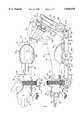
- FIG. 1is a pictorial illustration of an orthosis which is constructed and used in accordance with the present invention
- FIG. 2is an illustration of a right anterior arm of a patient
- FIG. 3is a side elevational view illustrating the manner in which the arm of the patient is gripped by upper and lower cuffs of the orthosis of FIG. 1;
- FIG. 4is a plan view, taken generally along the line 4--4 of FIG. 3, further illustrating the relationship of the lower cuff of the orthosis to a wrist and hand of the patient;
- FIG. 5is a side elevational view, generally similar to FIG. 3, illustrating the manner in which the orthosis effects pronation of the hand of the patient;
- FIG. 6is a plan view, taken generally along the line 6--6 of FIG. 5 further illustrating the relationship of the lower cuff of the orthosis to the wrist and hand of the patient;
- FIG. 7is a side elevational view, generally similar to FIG. 3, illustrating the manner in which the orthosis effects supination of the hand of the patient;
- FIG. 8is a plan view, taken generally along the line 8--8 of FIG. 7, further illustrating the relationship of the lower cuff of the orthosis to the wrist and hand of the patient;
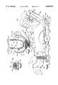
- FIG. 9is a fragmentary sectional view, taken generally along the line 9--9 of FIG. 1, illustrating the relationship of the lower cuff to a drive assembly which rotates the lower cuff;
- FIG. 10is a fragmentary sectional view, taken generally along the line 10--10 of FIG. 9, illustrating the manner in which a pair of pins engage a track in a main gear in the drive assembly to rotatably support the main gear;
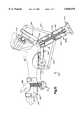
- FIG. 11is a side elevational view, generally similar to FIG. 3, of a second embodiment of the orthosis.
- FIG. 12is a side elevational view, generally similar to FIG. 3, of a third embodiment of the orthosis.
- FIG. 1An orthosis 20 for effecting relative movement between bones in an arm of a patient is illustrated in FIG. 1. Although it is preferred to use the orthosis 20 to effect relative movement between bones in an arm of a patient, it is contemplated that an orthosis constructed in accordance with the present invention could be utilized to effect movement between bones in other portions of a patient's body. Of course, the size and/or the relationship of various components of the orthosis 20 may be modified to adapt the orthosis for use with other portions of a patient's body.
- the orthosis 20includes a base 22.
- the base 22includes a lower cuff arm 24 which is adapted to extend along a lower portion of an arm of a patient.
- the base 22also includes an upper cuff arm 26 which is adapted to extend along an upper portion of an arm of a patient.
- the lower cuff arm 24 and upper cuff arm 26are interconnected at a pivot connection 28.
- a first or lower cuff 32is connected with the lower cuff arm 24 by a main drive assembly 34.
- the lower cuff 32grips the wrist and hand of a patient. If desired, the lower cuff 32 could be constructed so as to grip only the wrist of the patient.
- the main drive assembly 34is operable to rotate the lower cuff 32 and the gripped portion of the wrist and hand of the patient about an axis 36.
- the axis 36extends parallel to a longitudinal central axis of the lower cuff arm 24.
- the axis 36extends along the lower portion of the arm of the patient through the wrist and elbow. Rotation of the lower cuff 32 about the axis 36 by the main drive assembly 34 varies the extent of pronation and/or supination of the hand of the patient.
- a second or upper cuff 42is fixedly connected with the upper cuff arm 26.
- the upper cuff 42grips the upper portion of the arm of the patient.
- the upper cuff 42holds the upper portion of the arm of the patient against movement relative to the upper cuff arm 26 and lower cuff arm 24 during rotation of the lower cuff 32 about the axis 36.
- a third or center cuff 44is disposed on the lower cuff arm 24 and is engageable with the lower portion of the arm of the patient.
- the center cuff 44is ineffective to restrain movement of bones in the lower portion of the arm of the patient.
- the center cuff 44merely provides a support for the lower arm of the patient to increase the patient's comfort during use of the orthosis 20.
- the main drive assembly 34includes a main gear 48 which is connected with the lower cuff arm 24.
- the main gear 48 and lower cuff 32have central axes which are coincident with the axis 36.
- the main gear 48 and lower cuff 32are rotated together about the axis 36 during operation of the drive assembly 34.
- the lower cuff 32extends through a central opening 52 (FIG. 9) in the main gear 48.
- the main gear 48could be connected with one end portion of the lower cuff 32 so that the lower cuff does not extend through the main gear. It is believed that it will be preferred to have the lower cuff 32 extend through the main gear 48 in order to provide a solid interconnection between the lower cuff 32 and the main gear and to promote the stability of the lower cuff relative to the main drive assembly 34.
- the main drive assembly 34includes a worm or drive gear 56 (FIG. 9) which is disposed in meshing engagement with the main gear 48.
- the drive gear or worm 56is rotatably mounted on the lower cuff arm 24 and is fixedly connected with a shaft 58.
- a knob 60 on an outer end portion of the shaft 58is manually rotatable to rotate the drive gear 56 and main gear 48. As this occurs, the main gear 48 and lower cuff 32 are rotated about the axis 36 (FIG. 1). It is contemplated that the main drive assembly 34 could have a different construction if desired.
- FIG. 2a right arm 66 of the patient is illustrated in FIG. 2.
- the arm 66 of the patientextends between a hand 68 and shoulder 70 of the patient.
- the right arm 66 of the patientincludes a wrist 74, a lower portion or forearm 76, an elbow 78, and an upper portion 80.
- the wrist 74is the region where the hand 68 is joined with the lower portion 76 of the arm 66 of the patient.
- the elbow 78is the region where the lower portion 76 of the arm 66 and the upper portion 80 of the arm are joined.
- the lower portion 76 of the arm 66includes a radius bone 84 and an ulna bone 86.
- the radius 84has a distal end portion or capitulum 90 at the wrist 74.
- the radiushas a proximal end portion or capitulum 92 at the elbow 78.
- the ulna 86has a distal end portion or capitulum 94 at the wrist 74.
- the ulna 86has a proximal end portion or capitulum 96 at the elbow 78.
- the upper portion 80 of the arm 66extends between the shoulder 70 and elbow 78.
- the upper portion 80 of the armincludes the humerus bone 100.
- the humerus 100has a distal end portion or capitulum 102 which cooperates with the proximal end portions 92 and 96 of the radius 84 and ulna 86.
- the humerus 100has a proximal end portion 104 which cooperates with the shoulder 70.
- Pronation of the hand 68occurs when the hand is turned so that the palmar or anterior side of the hand and wrist 74 face downward and the opposite or posterior side of the hand and wrist face upward.
- Supination of the hand 68occurs when the hand is turned so that the palmar or anterior side of the hand and wrist 74 face upward and the opposite or posterior side of the hand and wrist face downward.
- the radius and ulna 84 and 86move relative to each other.
- the orthosis 20grips the wrist 74 and upper portion 80 of the arm 66 of the patient to isolate movement to the radius 84 and ulna 86 during pronation and/or supination of the hand.
- the orthosis 20could be used with the left arm of a patient. It should also be understood that the orthosis 20 may be used with a portion of a patient's body other than an arm.
- the orthosis 20is designed to isolate relative movement of a portion of a body disposed on one side of a joint from a portion of a body disposed on the other side of the joint.
- the orthosis 20isolates rotational movement of the distal end portions 90 and 94 of the radius and ulna 84 and 86 from the upper portion 80 of the arm 66.
- the lower cuff 32firmly grips and transmits force from the main drive assembly 34 to the wrist 74 of a patient (FIGS. 3 and 4).
- the lower cuff 32includes a pair of generally parallel sidewalls 110 and 112 (FIGS. 1, 3, 4, and 9).
- the sidewalls 110 and 112are integrally formed as one piece of a polymeric material having sufficient rigidity to be self-supporting and to apply force against the wrist 74 (FIG. 3) of the arm 66.
- the sidewalls 110 and 112have sufficient flexibility to enable them to be flexed to a limited extent and pressed firmly against the wrist 74.
- the sidewalls 110 and 112 of the lower cuff 32grip the hand 68 connected with the arm 66.
- An arcuate connector wall 114(FIG. 9) extends between and is integrally formed as one piece with the sidewalls 110 and 112.
- the connector wall 114is sufficiently flexible to enable the connector wall to deflect to accommodate hands 68 of different sizes. If desired, the axial extent of the side walls 110 and 112 could be reduced so that they would be effective to grip only the wrist 74.
- the axis 36(FIG. 3), about which the lower cuff 32 and main gear 48 rotate, extends midway between the sidewalls 110 and 112 (FIG. 4).
- the axis 36is offset upward (as viewed in FIG. 3) from the center of curvature of the connector wall 114 (FIG. 3).
- the axis 36extends parallel to a longitudinal central axis of the connector wall 114.
- the axis 36extends parallel to a longitudinal central axis of the lower cuff arm 24 and extends through the wrist 74 and elbow 78.
- the sidewalls 110 and 112 of the lower cuff 32include a pair of sections 118 and 120 which securely grip the wrist portion 74 of the arm 66 (FIGS. 1, 3, 6, 7 and 8).
- the sections 118 and 120 of the sidewalls 110 and 112are firmly pressed against opposite sides of the wrist 74 by a wrist strap 122.
- the wrist strap 122presses a resilient foam lining 123 (FIG. 9) on the inner side of the lower cuff 32 firmly against the wrist 74.
- the distal end portions or capitula 90 and 94 of the radius and ulna 84 and 86are firmly gripped between the opposite sections 118 and 120 (FIG. 1) of the sidewalls 110 and 112 of the lower cuff 32. This results in the distal end portions 90 and 94 of the radius and ulna 84 and 86 being held against movement, in directions perpendicular to the axis 36, by the sections 118 and 120 of the sidewalls 110 and 112 of the lower cuff 32 during rotation of the lower cuff 32 about the axis 36. However, the distal end portions 90 and 94 of the radius and ulna 84 and 86 can rotate somewhat about their central axes during rotation of the lower cuff 32 about the axis 36.
- the wrist strap 122has an end portion 124 (FIG. 3) which is fixedly connected to the section 120 of the sidewall 112 of the lower cuff 32.
- the wrist strap 122extends through a ring 126 (FIG. 6) mounted on the section 118 of the opposite sidewall 110.
- the wrist strap 122is formed with sections of hook and loop fastener material, i.e.,”VELCRO" (trademark).
- the strap section of loop fastener materialcan be pressed against the strap section of hook fastener material to interconnect the sections of the wrist strap 122.
- the wrist strap 122transmits force between the sections 118 and 120 of the sidewalls 110 and 112 of the lower cuff 32. This force presses the sections 118 and 120 of the sidewalls 110 and 112 of the lower cuff 32 firmly against the wrist 74 to grip the distal end portions 90 and 94 of the radius and ulna 84 and 86.
- a different type of cuff with a different type of strap or other type of interconnectioncould be utilized if desired, as long as the lower cuff 32 is firmly pressed against the wrist 74.
- the sections 118 and 120 of the side walls 110 and 112 of the lower cuff 32could completely enclose the wrist 74 and could have overlapping portions connected to each other.
- a second or hand strap 130is connected with the sidewalls 110 and 112 of the lower cuff 32 in the same manner as in which the wrist strap 122 is connected with the sidewalls 110 and 112 of the lower cuff 32.
- the hand strap 130presses the sidewalls 110 and 112 of the lower cuff firmly against the palmar side and back side of the hand 68 (FIGS. 3 and 4) to firmly grip the hand.
- both the hand 68 and wrist 74are firmly gripped by the lower cuff 32.
- the portion of the lower cuff 32 which grips the wrist 74is particularly important since it also grips the distal end portions 90 and 94 of the radius and ulna bones 84 and 86.
- the upper cuff 42(FIGS. 1 and 3) has the same general construction as the lower cuff 32.
- the upper cuff 42grips the upper portion 80 of the arm 66 and holds the upper portion 80 of the arm 66 against movement relative to the lower portion 76 of the arm 66 during rotation of the cuff 32 about the axis 36.
- the upper cuff 42is fixedly connected to the upper cuff arm 26 of the base 22 by a connector block 134.
- the upper cuff 42includes a pair of sidewalls 136 and 138.
- the sidewalls 136 and 138(FIG. 1) are integrally formed as one piece of a polymeric material having sufficient rigidity to be self-supporting while still enabling the material to be flexed to a limited extent.
- the sidewalls 136 and 138 of the upper cuff 42are formed of the same material as the sidewalls 110 and 112 of the lower cuff 32.
- a central axis of the upper cuff 42is disposed midway between the sidewalls 136 and 138 and extends parallel to the longitudinal central axis of the upper cuff arm 26.
- the central axis of the upper cuff 42intersects the axis 36 about which the lower cuff 32 is rotated by operation of the main drive assembly 34.
- An arcuate connector section 140extends between the sidewalls 136 and 138 of the upper cuff 42.
- the connector section 140 of the upper cuffis fixedly connected to the upper cuff arm 26 by the connector block 134.
- a pair of straps 144 and 146are connected with the sidewall 136 of the upper cuff 42 and are engageable with rings 148 and 150 connected with the sidewall 138 of the upper cuff 42.
- the straps 144 and 146extend through the rings 148 and 150 and press the two sidewalls 136 and 138 of the upper cuff 42 firmly against the upper portion 80 of a patient's arm.
- the straps 144 and 146have sections formed of hook and loop fastener material, i.e., "VELCRO" (trademark).
- the hook and loop fastener sections in each of the straps 144 and 146connect sections of the straps together.
- the straps 144 and 146interconnect the two sidewalls 136 and 138 and press them together.
- the upper cuff 42 and/or straps 144 and 146could have a different construction if desired, so long as the upper cuff firmly holds the upper portion 80 of the arm of a patient against movement relative to the lower portion 76 of the arm during rotation of the lower cuff 32 about the axis 36.
- the upper cuff 42is fixedly connected to the upper cuff arm 26 through the connector block 134. If desired, the upper cuff 42 could be mounted for axial movement along the upper cuff arm 26. If this was done, a suitable fastener arrangement would be provided to lock the upper cuff 42 in any desired position along the upper cuff arm 26.
- a third or center cuff 44(FIGS. 3 and 4) is provided to support the lower portion 76 of the arm 66 of the patient.
- the center cuff 44is formed of the same polymeric material as the lower cuff 32 and upper cuff 42.
- the center cuff 44increases the comfort of the patient by providing a resting location for the lower portion 76 of the patient's arm 66.
- the center cuff 44does not restrain the lower portion 76 of the patient's arm 66.
- the base 22(FIGS. 1 and 3) of the orthosis 20 supports the lower cuff 32 and upper cuff 42.
- the base 22supports the lower cuff 32 and main drive assembly 34 in such a manner as to enable the lower cuff to be rotated relative to the base.
- the base 20includes the lower and upper cuff arms 24 and 26.
- the longitudinally extending lower cuff arm 24includes a base section 156 and an extension section 158.
- the extension section 158is telescopically received in the base section 156.
- the center cuff 44is fixedly connected to the base section 156 of the lower cuff arm 24.
- the extension section 158can be moved axially into and out of the base section 156 to vary the length of the lower cuff arm 24.
- the extension section 158is moved axially into the base section 156 to decrease the length of the lower cuff arm 24.
- the extension sectionis pulled axially out of the base section to increase the length of the lower cuff arm 24. This enables the orthosis 20 to accommodate patients having arms 66 with lower portions 76 of different lengths.
- the retainer assembly 160includes a bolt (not shown) having a head end portion disposed within the extension section 158 and a shank portion which extends through a slot 164 (FIG. 3) in the extension section 158.
- the shank portion of the boltalso extends through a hole (not shown) in the base section 156 of the lower cuff arm 24.
- a knob 166is threaded onto the shank portion of the bolt.
- the head end portion of the boltfirmly presses the extension section 158 against the base section 156 of the lower cuff arm 24. This locks the base and extension sections 156 and 158 against axial movement relative to each other.
- the extension section 158can be moved relative to the base section 156 to either increase or decrease the axial extent of the lower cuff arm 24.
- the base section 156 and extension section 158 of the lower cuff arm 24both have rectangular cross-sectional configurations.
- the rectangular cross-sectional configurations of the base section 156 and extension section 158prevents rotational movement between the base and extension sections about their coincident longitudinal central axes.
- the coincident longitudinal central axes of the base section 156 and extension section 158 of the lower cuff arm 24extend parallel to the axis 36 about which the main drive assembly 24 rotates the lower cuff 32.
- the upper cuff arm 26is pivotally connected with the base section 156 of the lower cuff arm 24 at the pivot connection 28.
- a pair of identical retainer assemblies 170 and 172(FIG. 1) are operable between an engaged condition and a release condition. When the retainer assemblies 170 and 172 are in the engaged condition, they hold the lower and upper cuff arms 24 and 26 against movement relative to each other about the pivot connection 28. When the retainer assemblies 170 and 172 are in the disengaged condition they enable the lower cuff arm 24 to pivot relative to the upper cuff arm 26 at the pivot connection 28 about an axis which extends perpendicular to the axis 36.
- the upper cuff arm 26When the retainer assemblies 170 and 172 are in a disengaged condition, the upper cuff arm 26 is pivotal in a clockwise direction (as viewed in FIG. 1) about the pivot connection 28. This enables the upper cuff arm 26 to move to a position in which the longitudinal central axis of the upper cuff arm 26 is coincident with the longitudinal central axis of the lower cuff arm 24.
- the base 22has a straight linear configuration.
- the upper cuff armis pivotal in a counterclockwise direction from the orientation in which the base 22 has a straight linear configuration, through a range of approximately 90° about the pivot connection 28.
- the retainer assemblies 170 and 172are operable from the disengaged condition to the engaged condition to lock the upper cuff arm 26 in any desired angular orientation relative to the lower cuff arm 24.
- the upper cuff arm 26is movable between a position in which its longitudinal axis extend perpendicular to and intersects a longitudinal central axis of the lower cuff arm 24 to a position in which the longitudinal central axis of the upper cuff arm 26 is coincident with the longitudinal central axis of the lower cuff arm 24.
- the retainer assemblies 170 and 172may be engaged when the upper cuff arm 26 is at any position between the two limit positions to hold the upper cuff arm 26 against pivotal movement relative to the lower cuff arm 24.
- the retainer assembly 172(FIGS. 1 and 3) includes a connector link 180 having an end portion which is pivotally connected at 182 with the base section 156 of the lower cuff arm 24.
- the connector link 180has a longitudinally extending slot 186 at the end of the connector link opposite from the pivot connection 182.
- a shank portion of a bolt (not shown) in the retainer assembly 172extends through the slot 186 and into a manually rotatable knob 188.
- a head end portion of the boltis disposed within the upper cuff arm 26.
- the retainer assembly 172Upon rotation of the knob 188 in a clockwise direction (as viewed in FIG. 1) the retainer assembly 172 is operated from the disengaged condition to the engaged condition. As this occurs, the connector link 180 is firmly clamped between spacers 190 on the shank portion of the bolt and the knob 188 to lock the upper cuff arm 26 against movement relative to the lower cuff arm 24.
- the connector link 180Upon rotation of the knob 188 in a counterclockwise direction (as viewed in FIG. 1) the connector link 180 is released and the upper cuff arm 26 is pivotal relative to the lower cuff arm 24 about the pivot connection 28.
- the retainer assembly 170has the same construction as the retainer assembly 172.
- the retainer 170includes a connector link 194 and a knob 196 (FIG. 1).
- the knob 196 in the retainer assembly 170is rotatable to an engaged condition in which the connector link 194 is firmly gripped and a release condition in which the connector link is movable relative to the knob 196.
- the lower cuff arm 24 and the upper cuff arm 26are movable relative to each other about the pivot connection 28.
- the lower cuff arm 24could be fixedly connected with the upper cuff arm 26.
- the upper cuff arm 26could be formed as one piece with the base section 156 of the lower cuff arm 24.
- the upper cuff arm 26 and base section 156 of the lower cuff arm 24could be disposed in a linear orientation or in an angular orientation, as shown in FIG. 1.
- the orthosis 20in such a manner as to enable the lower cuff arm 24 and upper cuff arm 26 to move relative to each other to accommodate different orientations of the upper portion 80 (FIG. 3) of the arm 66 of a patient relative to the lower portion 76 of the arm.
- the main drive assembly 34(FIG. 3) rotates the lower cuff 32 about the axis 36 which extends through the wrist 74 and elbow 78 of the arm 66 of the patient.
- the axis 36extends generally parallel to and is at least reasonably close to being coincident with the longitudinal central axis of the lower portion 76 of the arm 66.
- the axis 36extends along the radius and ulna 84 and 86 (FIG. 2).
- axis 36is generally parallel to central axes of the radius and ulna 84 and 86, the axis 36 is offset from the central axes of the radius and ulna. A portion of the axis 36 may extend through space between the radius 84 and ulna 86. It is contemplated that the precise location of the radius and ulna 84 and 86 relative to the axis 36 will vary from patient to patient.
- the main drive assembly 34is connected with the lower cuff arm 24 and is operable to rotate the lower cuff 32 about the axis 36.
- the lower cuff 32extends through the central opening 52 (FIG. 9) in the main gear 48.
- the sidewall 110 of the lower cuffis fixedly connected with the main gear 48 by a pair of right angle brackets 202 and 204 (FIGS. 5 and 6).
- the brackets 202 and 204connect the sidewall 110 of the lower cuff 32 to a wall 210 (FIG. 9) of the main gear 48.
- the main gear 48could be integrally formed as one piece with the lower cuff 32.
- the brackets 202 and 204connect the lower cuff 32 to the main gear 48 with an entry opening 214 (FIG. 9) to the lower cuff facing in the same direction, that is upward as viewed in FIG. 9, as the generally U-shaped central opening 52 in the main gear 48.
- the central opening 52 in the main gear 48has an open upper (as viewed in FIG. 9) portion 215 through which the side walls 110 and 112 of the lower cuff 32 extend.
- the side walls 110 and 112 of the lower cuff 32define the entry opening 214 to the lower cuff.
- the entry opening 214 to the lower cuff 32is vertically aligned (as viewed in FIG. 9) with the open upper portion 215 of the opening through the main gear 48.
- the patient's hand 68can be moved downward through the opening 214 (FIG. 9) into the lower cuff 32 and into the central opening 52 in the main gear 48.
- the wrist 74 of the patientwill be disposed on one side, i.e., the right side as viewed in FIG. 3, of the main gear 48 while ends of fingers 218 will be disposed on the opposite side, i.e., the left side, as viewed in FIG. 3, of the main gear 48.
- the palmar portion of the hand 68 of the patientwill be disposed in the lower cuff 32 and in the central opening 52 in the main gear 48.
- the axis 36will extend through the hand 68, wrist 74, and the lower portion 76 of the arm 66 of the patient.
- the lower cuff 32could be connected with the main gear 48 in a different manner.
- the lower cuff 32may only have a portion which grips the wrist 74 in the arm 66 of the patient and does not have a portion which grips the hand 68 of the patient. This construction would result in the portion of the lower cuff 32 disposed to the left (as viewed in FIG. 3) of the main gear 48 being omitted.
- the lower cuff arm 24could be extended so that the main drive assembly 34 is disposed to the left (as viewed in FIG. 3) of the fingers 218 on the hand 68 of the patient. The lower cuff 32 would then extend past the ends of the fingers 218 on the hand of the patient and be connected to the main gear 48.
- the main gear 48includes an arcuate array 219 (FIG. 9) of gear teeth having a configuration of a portion of a circle.
- the cuff 32extends upward (as viewed in FIG. 9) between opposite ends 221 and 223 of the arcuate array 219 of gear teeth and through the open upper portion of the U-shaped central opening 52 in the main gear 50.
- the arcuate array 219 of gear teethhas a central axis which is coincident with the axis 36 (FIG. 1) about which the main gear 48 rotates.
- the arcuate array 219 (FIG. 9) of gear teethcould be integrally formed as one piece with the side walls 110 and 112 and connector wall 114 of the lower cuff 32.
- the main gear 48is supported for rotation about the axis 36 by the lower cuff arm 24.
- the main gear 48has a pair of identical tracks or grooves 220 and 222 (FIG. 10) disposed on opposite sides of the gear.
- the grooves 220 and 222form portions of circles and have centers of curvature which are disposed on the axis 36.
- a pair of pinsengages each of the grooves 220 and 222.
- a cylindrical pin 224extends into the groove 220 and a cylindrical pin 226 extends into the groove 222.
- the pins 224 and 226are supported in a coaxial relationship on the right (as viewed in FIG. 9) side of the lower cuff arm 24 by a mounting block 230.
- a second mounting block 232is disposed adjacent to the left side of the lower cuff arm 24 and supports a second pair of pins which engage the tracks 220, 222 in the same manner in which the pins 224 and 226 engage the tracks. Therefore, a pair of pins extends into each of the tracks 220 and 222 to support the main gear 48 for rotation relative to the lower cuff arm 24.
- a different mounting arrangementcould be utilized for supporting the main gear 48.
- a pair of arcuate ribscould extend from opposite sides of the wall 210 of the main gear 48. These ribs would extend into arcuate tracks which are fixedly connected with the lower cuff arm 24 and have a common central axis which is coincident with the axis 36.
- the drive gear 56(FIG. 9) is fixedly connected with the shaft 58 and is disposed on meshing engagement with the arcuate array 219 of teeth on the main gear 48.
- the drive gear 56is a worm.
- the knob 60Upon rotation of the knob 60, the worm 56 is rotated about an axis 240 which extends perpendicular to and is offset from the axis 36 (FIG. 1).
- a spur gearcould be substituted for the drive gear 56.
- a suitable motorcould be provided in place of the manually rotatable knob 60 to rotate the drive gear 56.
- Viscoelastic body tissue connecting the proximal end portions 92 and 96 (FIG. 2) of the radius and ulna 84 and 86 with the humerus 100 in the arm 66 of a patientmay require stretching to enable the hand 68 of the patient to move through a desired range of motion in supination and/or pronation.
- the viscoelastic body tissue connected with the proximal end portions 92 and 96 of the radius and ulna 84 and 86is to be stretched, the upper portion 80 of the arm 66 of the patient is positioned in the upper cuff 42 (FIG. 1) of the orthosis 20.
- the straps 144 and 146are loosely tightened around the upper portion 80 of the arm 66 to initially position the upper cuff arm 26 relative to the upper portion 80 of the patient's arm 66.
- the retainer assemblies 170 and 172(FIG. 1) are then loosened and the lower cuff arm 24 is positioned relative to the lower portion 76 of the patient's arm 66 (FIG. 2). At this time, the retainer 160 (FIG. 3) is loose.
- the extension section 158 of the lower cuff arm 24is moved to position the lower cuff 32 relative to the hand 68 (FIG. 3).
- the retainer assemblies 170, 172are tightened to fixedly interconnect the lower cuff arm 24 and upper cuff arm 26.
- the retainer assembly 160is also tightened to hold the extension section 158 against movement relative to the base section 156 of the lower cuff arm 24.
- the upper cuff straps 144 and 146are tightened to firmly grip the upper portion 80 of the patient's arm.
- the hand 68is positioned in the lower cuff 32 by moving the hand through the opening 214 (FIG. 9) in the lower cuff 32.
- the wrist strip 122 and hand strap 130are then tightened. This presses the sidewalls 110 and 112 of the lower cuff 32 against the palmar and back sides of the wrist 74 and hand 68.
- the distal end portions 90 and 94 of the radius and ulna 84 and 86are firmly gripped between the sidewalls 110 and 112 of the lower cuff 32.
- the hand 68is firmly gripped between the sidewalls 110 and 112 of the lower cuff.
- the upper cuff 42firmly grips the upper portion 80 of the patient's arm 66.
- the lower portion 76 and the upper portion 80 of the patient's arm 66are held against movement relative to each other.
- the lower portion 76 of the arm 66(FIG. 3) is held against movement relative to the lower cuff arm 24 by the lower cuff 32.
- the upper portion 80 of the arm 66is held against movement relative to the upper cuff arm 26 by the upper cuff 42.
- the only way to move the arm 66is at the shoulder 70.
- the knob 60 of the main drive assembly 34is rotated in a counterclockwise direction (as viewed in FIG. 3).
- Counterclockwise rotation of the knob 60causes the drive gear 56 (FIG. 9) to rotate the main gear 48 about the axis 36 from the initial position shown in FIGS. 3 and 4 toward the position shown in FIGS. 5 and 6.
- the sections 118 and 120 (FIG. 1) of the lower cuff 32firmly grip the distal end portions 90 and 94 (FIG. 2) of the radius and ulna 84 and 86. Therefore, the distal end portions 90 and 94 of the radius and ulna 84 and 86 are rotated with the lower cuff 32 about the axis 36.
- the proximal end portions 92 and 96 of the radius and ulna 84 and 86move relative to the distal end portion 102 of the humerus.
- the radius 84will revolve partially about the ulna 86.
- the proximal end portion 96 of the ulnawill articulate with the distal end portion 102 of the humerus 100.
- the rotational motion imparted by the lower cuff 32 to the distal end portions 90 and 94 of the radius and ulna 84 and 86will be isolated to the region between the elbow 78 and wrist 74 in the arm 66 of the patient.
- the main drive assembly 34can be operated to increase the extent of supination of the hand 68 from the initial orientation of FIGS. 3 and 4.
- the knob 60is rotated in a clockwise direction (as viewed in FIG. 3).
- the extent of supination of the hand 68is increased as the hand is moved from the position shown in FIGS. 3 and 4 toward the position shown in FIGS. 7 and 8.
- the orthosis 20could be modified to be used with other portions of a patient's body if desired.
- the orthosis 20could be constructed in such a manner as to effect pronation and/or supination of a foot of a patient.
- the orthosis 20 illustrated in FIGS. 1-10is used to effect supination and/or pronation of the hand 68 without changing the extent of bending of the elbow 78.
- the orthosisis constructed in such a manner as to effect supination and/or pronation of the hand and to effect bending of the elbow in either flexion or extension. Since the embodiment of the invention illustrated in FIG. 11 is generally similar to the embodiment of the invention illustrated in FIGS. 1-10, similar numerals will be utilized identify similar components, the suffix "a" being associated with the numerals identifying components of FIG. 11 in order to avoid confusion.
- An orthosis 20aincludes a base 22a.
- the base 22ahas a lower cuff arm 24a and an upper cuff arm 26a.
- a lower cuff 32ais connected with the lower cuff arm 24a by a main drive assembly 34a.
- An upper cuff 42afixedly connected with the upper cuff arm 26a.
- a secondary drive assembly 300is provided to effect relative movement between the lower and upper cuff arms 24a and 26a to bend the arm 66a of the patient at the elbow 78a.
- the secondary drive assembly 300includes a main drive gear 302 which is rotatably supported on a shaft 304 which extends through end portions of the lower cuff arm 24a and upper cuff arm 26a.
- a rack gear 308is disposed in meshing engagement with the drive gear 302.
- the drive gearUpon rotation of a suitable knob, (not shown) connected with the drive gear 302 through the shaft 304, the drive gear is effective to move the rack 308. Movement of the rack 308 moves the upper cuff arm 26a relative to the lower cuff arm 24a.
- a latch assembly 312is operated from a disengaged condition to an engaged condition. When the latch assembly 312 is in the disengaged condition, it is spaced from the drive gear 302 and is connected to the lower cuff arm 24a. When the latch assembly 312 is in the engaged condition it interconnects the cuff arm 24a and drive gear 302. Thus, when the latch assembly 312 is in the engaged condition it engages the teeth on the drive gear 302 to hold the drive gear against rotation relative to the lower cuff arm 24a.
- the rack 308By rotating the main drive gear 302 in a clockwise direction (as viewed in FIG. 11) with the latch assembly 312 disengaged, the rack 308 is moved to effect clockwise (as viewed in FIG. 11) pivotal movement of the upper cuff arm 26a relative to the lower cuff arm 24a.
- Forceis transmitted from the lower cuff 32a to the distal ends 90 and 94 (FIG. 2) of the radius and ulna bones 84 and 86 in the lower portion 76a (FIG. 11) to the arm 66a of the patient.
- Forceis transmitted from the upper cuff 42a to the upper portion 80a of the arm of the patient.
- the elbow 78ais bent in extension.
- the latch assembly 312is operated from the disengaged condition to the engaged condition to hold the upper cuff arm 26a against movement relative to the lower cuff arm 24a.
- the knob (not shown) connected with the main drive gear 302is rotated to effect rotation of the main drive gear in a counterclockwise direction (as viewed in FIG. 11).
- the upper cuff arm 26ais rotated in a counterclockwise direction relative to the lower cuff arm 24a.
- the latch assembly 312is in the disengaged condition.
- the latch assembly 312is operated to the engaged condition to hold the gear 302 against rotation relative to the lower and upper cuff arms 24a and 26a.
- a rack and pinion type drive assembly 300is provided to effect bending of the arm 66a at the elbow 78a.
- a screw and nut type drive assemblyis utilized to effect bending the arm at the elbow. Since the embodiment of the invention illustrated in FIG. 12 is generally similar to the embodiments of the invention illustrated in FIGS. 1-11, similar numerals will be utilized to identify similar components, the suffix letter "b" being associated with the components of FIG. 12 in order to avoid confusion.
- An orthosis 20bincludes a lower cuff arm 24b and an upper cuff arm 26b.
- a lower cuff 32bis connected with the lower cuff arm 24b by a drive assembly 34b.
- An upper cuff 42bis connected with the upper cuff arm 26b.
- the main drive assembly 34bUpon operation of the main drive assembly 34b, the lower cuff 32b is rotated about an axis 36b to effect pronation or supination of a hand 68b connected with an arm 66b of a patient, in the manner explained in conjunction with the embodiment of the invention illustrated in FIGS. 1-10.
- a secondary drive assembly 300bis connected with the lower cuff arm 24b and upper cuff arm 26b to effect bending of an elbow 78b.
- the secondary drive assembly 300bincludes an externally threaded member or screw 330 which is rotatably supported within a housing 332.
- a central axis of the screw 330extends through the elbow 78b.
- the central axis of the screw 330extends midway between pivot connections 334 and 336 between the lower cuff arm 24b and upper cuff arm 26b and the housing 332 for the secondary drive assembly 300b.
- a manually rotatable knob 340is connected with the lower end (as viewed in FIG. 12) of the screw 330.
- An actuator member or block 344has internal thread convolutions which engage external thread convolutions on the screw 330.
- the actuator member 344Upon rotation of the input member or knob 340, the actuator member 344 is moved away from the pivot connections 334 and 336. As this occurs, drive links 348 and 350 pivot the lower cuff arm 24b and upper cuff arm 26b about the pivot connections 334 and 336. This effects bending of the elbow 78b in extension. Thus, force is transmitted from the lower cuff 32b to distal ends of the radius and ulna bones in the arm 66b of the patient. Force is transmitted from the upper cuff 42b to the upper portion of the arm of the patient.
- the knob 340When the knob 340 is rotated to move the actuator member block 344 toward the pivot connections 334 and 336, the drive links 348 and 350 effect movement of the lower cuff arm 24b and upper cuff arm 26b to bend the elbow 78b in flexion.
- the drive assembly 300bcould have many different constructions, in the illustrated embodiment of the invention, the drive assembly 300b has the same construction as is disclosed in U.S. Pat. No. 5,503,619 issued Apr. 2, 1996 to Peter M. Bonutti and entitled, "Orthosis for Bending Wrist".
- the manner in which the arm 66b is bent in flexion or extensionis the same as is disclosed in U.S. Pat. No. 5,453,075 issued Sep. 26, 1994 to Peter M. Bonutti and entitled "Orthosis With Distraction Through Range of Motion".
- the present inventionprovides a new and improved apparatus and method for use in effecting relative movement between bones in an arm 66 or other portion of a body of a patient.
- the apparatusincludes an orthosis 20 having a lower cuff 32 which is rotatable relative to a base 22 by a drive assembly 34 and an upper cuff 42 which is connected to the base.
- the lower cuff 32grips a wrist 74 of the patient while the upper cuff 42 grips the upper portion 80 of an arm 66 of the patient.
- the drive assembly 34rotates the lower cuff 32 about an axis 36 which extends along the lower portion 76 of the arm 66.
- the drive assembly 34 for rotating the lower cuff 32includes a main gear 48 which is connected with the lower cuff.
- the lower cuffmay extend through an opening 52 in the main gear 48.
- a drive gear connected with the base 22is disposed in engagement with the main gear and is rotatable relative to the base to rotate the main gear and lower cuff 32.
- a second drive assembly 300 or 300bmay be provided to move sections 24a, 26a or 24b, 26b of the base relative to each other and effect bending of the elbow 78a or 78b in the arm of the patient.
- the second drive assembly 300 or 300bis operable to pivot the sections of the base about an axis which extends transversely to the axis 36a or 36b about which the lower cuff is rotated.
Landscapes
- Health & Medical Sciences (AREA)
- Life Sciences & Earth Sciences (AREA)
- Veterinary Medicine (AREA)
- Public Health (AREA)
- General Health & Medical Sciences (AREA)
- Animal Behavior & Ethology (AREA)
- Biomedical Technology (AREA)
- Vascular Medicine (AREA)
- Heart & Thoracic Surgery (AREA)
- Engineering & Computer Science (AREA)
- Orthopedic Medicine & Surgery (AREA)
- Nursing (AREA)
- Epidemiology (AREA)
- Pain & Pain Management (AREA)
- Physical Education & Sports Medicine (AREA)
- Rehabilitation Therapy (AREA)
- Surgical Instruments (AREA)
Abstract
Description
Claims (128)
Priority Applications (1)
| Application Number | Priority Date | Filing Date | Title |
|---|---|---|---|
| US08/683,196US5848979A (en) | 1996-07-18 | 1996-07-18 | Orthosis |
Applications Claiming Priority (1)
| Application Number | Priority Date | Filing Date | Title |
|---|---|---|---|
| US08/683,196US5848979A (en) | 1996-07-18 | 1996-07-18 | Orthosis |
Publications (1)
| Publication Number | Publication Date |
|---|---|
| US5848979Atrue US5848979A (en) | 1998-12-15 |
Family
ID=24742964
Family Applications (1)
| Application Number | Title | Priority Date | Filing Date |
|---|---|---|---|
| US08/683,196Expired - LifetimeUS5848979A (en) | 1996-07-18 | 1996-07-18 | Orthosis |
Country Status (1)
| Country | Link |
|---|---|
| US (1) | US5848979A (en) |
Cited By (104)
| Publication number | Priority date | Publication date | Assignee | Title |
|---|---|---|---|---|
| US6007500A (en)* | 1998-01-28 | 1999-12-28 | Quintinskie, Jr.; John J. | Shoulder, rotator cuff, and elbow stretching machine |
| US6113562A (en)* | 1998-06-01 | 2000-09-05 | Peter M. Bonutti | Shoulder orthosis |
| US6142964A (en)* | 1997-03-27 | 2000-11-07 | Bodyworks Properties Limited | Multi-planar brace |
| US6165148A (en)* | 1999-07-23 | 2000-12-26 | Loretta M. Carr-Stock | Wrist/hand/finger orthosis |
| US6241643B1 (en)* | 1998-03-25 | 2001-06-05 | Soren A. Loft | Arm exercising device |
| WO2001068028A3 (en)* | 2000-03-14 | 2002-12-27 | Orthologic Corp | Combination pro/supination and flexion therapeutic mobilization device |
| US6506172B1 (en)* | 2000-10-10 | 2003-01-14 | Dynasplint Systems, Inc. | Supinator/pronator therapy system to bring mobility to wrist, forearm and/or elbow |
| US20040010213A1 (en)* | 2002-07-10 | 2004-01-15 | Mav-Tech Medical L.L.C. | Stabilizer brace system |
| US20040097330A1 (en)* | 1999-08-20 | 2004-05-20 | Edgerton V. Reggie | Method, apparatus and system for automation of body weight support training (BWST) of biped locomotion over a treadmill using a programmable stepper device (PSD) operating like an exoskeleton drive system from a fixed base |
| US20040193086A1 (en)* | 2003-03-28 | 2004-09-30 | Cofre Ruth P. | Dynamic position adjustment device for extremities of the human body |
| US20040215111A1 (en)* | 2003-04-23 | 2004-10-28 | Bonutti Peter M. | Patient monitoring apparatus and method for orthosis and other devices |
| US20050197605A1 (en)* | 2004-03-08 | 2005-09-08 | Bonutti Boris P. | Orthosis |
| USD519638S1 (en) | 2004-07-22 | 2006-04-25 | Nordt Development Co., Inc. | Support brace member |
| USD519637S1 (en) | 2004-07-22 | 2006-04-25 | Nordt Development Co., Inc. | Support brace |
| USD520141S1 (en) | 2004-07-22 | 2006-05-02 | Nordt Development Co., Inc. | Support brace |
| USD521644S1 (en) | 2004-07-22 | 2006-05-23 | Nordt Development Co., Inc. | Support brace |
| US7066896B1 (en) | 2002-11-12 | 2006-06-27 | Kiselik Daniel R | Interactive apparatus and method for developing ability in the neuromuscular system |
| US20060184081A1 (en)* | 2002-05-28 | 2006-08-17 | Gilmour Robert F | Enhanced arm brace |
| ES2260986A1 (en)* | 2003-12-11 | 2006-11-01 | Asociacion Instituto De Biomecanica De Valencia | Orthesis for controlling pronosupination movement, allows control of rotary movement relative to wrist with respect to forearm axis |
| US20070055190A1 (en)* | 2004-03-08 | 2007-03-08 | Bonutti Boris P | Range of motion device |
| US20070100267A1 (en)* | 2005-10-28 | 2007-05-03 | Bonutti Boris P | Range of motion device |
| US20070099760A1 (en)* | 2005-11-02 | 2007-05-03 | Chung-San Liao | Arm exerciser |
| US20070219476A1 (en)* | 2006-03-20 | 2007-09-20 | Bonutti Boris P | Elbow orthosis |
| WO2007109638A2 (en) | 2006-03-20 | 2007-09-27 | Marctec, Llc | Elbow orthosis |
| US20070255190A1 (en)* | 2003-11-07 | 2007-11-01 | Patrick Sadok | Exoskeleton System for a Proportional Movement Biological Segment and Exoskeleton Assembly of a Said Systems |
| US20080072943A1 (en)* | 2004-05-11 | 2008-03-27 | Deborah Anne Forster | Crutch |
| WO2008036895A2 (en) | 2006-09-21 | 2008-03-27 | Marctec, Llc | Range of motion device |
| US20080097255A1 (en)* | 2006-10-20 | 2008-04-24 | National Cheng Kung University | Rehabilitation apparatus |
| US20080188356A1 (en)* | 2007-02-05 | 2008-08-07 | Bonutti Boris P | Knee orthosis |
| US20080234614A1 (en)* | 2003-11-12 | 2008-09-25 | Patel Amit V | Injury immobilization device |
| WO2008028190A3 (en)* | 2006-09-01 | 2008-10-30 | Worcester Polytech Inst | Two degree of freedom powered orthosis |
| US20080293551A1 (en)* | 2007-05-22 | 2008-11-27 | The Hong Kong Polytechnic University | Multiple joint linkage device |
| US7473234B1 (en)* | 2004-05-24 | 2009-01-06 | Deroyal Industries, Inc. | Brace with worm gear |
| WO2009015364A1 (en) | 2007-07-25 | 2009-01-29 | Bonutti Research Inc. | Orthosis apparatus and method of using an orthosis apparatus |
| US20090054820A1 (en)* | 2007-02-28 | 2009-02-26 | Weltner Thomas R | Static progressive pronation supination splint |
| WO2008047355A3 (en)* | 2006-10-16 | 2009-04-23 | Motorika Ltd | Methods and gyroscopic apparatus for rehabilitation training |
| US20090264799A1 (en)* | 2008-03-04 | 2009-10-22 | Bonutti Peter M | Shoulder ROM Orthosis |
| US7615019B2 (en) | 2004-07-22 | 2009-11-10 | Nordt Development Co., Llc | Potentiating support with side struts spanning hinge joint |
| US7615020B2 (en) | 2004-07-22 | 2009-11-10 | Nordt Development Co., Llc | Support with removable pressure/alignment ring |
| US7615027B2 (en) | 2004-07-22 | 2009-11-10 | Nordt Development Co., Llc | Support with framework fastened to garment |
| US7615021B2 (en) | 2004-07-22 | 2009-11-10 | Nordt Development Co., Llc | Clothing having expandable framework |
| US7615023B2 (en) | 2004-07-22 | 2009-11-10 | Nordt Development Co., Llc | Donning support with framework fastened to garment |
| US7615022B2 (en) | 2004-07-22 | 2009-11-10 | Nordt Development Co., Llc | Potentiating support with alignment opening for joint protuberance |
| US7618386B2 (en) | 2004-07-22 | 2009-11-17 | Nordt Development Co., Llc | Two-component compression collar clamp for arm or leg |
| US7618389B2 (en) | 2004-07-22 | 2009-11-17 | Nordt Development Co., Llc | Potentiating support with expandable framework |
| US20090287128A1 (en)* | 2008-05-15 | 2009-11-19 | Arni Thor Ingimundarson | Orthopedic devices utilizing rotary tensioning |
| US7621881B2 (en) | 2004-07-22 | 2009-11-24 | Nordt Development Co., Llc | Donning potentiating support with expandable framework spanning hinge joint |
| US7637884B2 (en) | 2004-07-22 | 2009-12-29 | Nordt Development Co., Llc | Shirt, pants and jumpsuit having expandable framework |
| US20100016773A1 (en)* | 2008-07-21 | 2010-01-21 | Anatomical Concepts, Inc. | Coordinated Cuff Displacement in an Orthotic Device |
| US20100016772A1 (en)* | 2008-07-21 | 2010-01-21 | Anatomical Concepts, Inc. | Multiple function ratcheting orthotic device |
| US7704219B2 (en) | 2004-07-22 | 2010-04-27 | Nordt Development Company, Llc | Wrist support |
| US7708708B2 (en) | 2004-07-22 | 2010-05-04 | Nordt Development Co., Ltd. | Donning potentiating support with expandable framework fastened to garment |
| US20100204804A1 (en)* | 2007-06-12 | 2010-08-12 | Commissariat A L'energie Atomique | Forearm rotation mechanism and orthesis which includes such a mechanism |
| US7988653B2 (en) | 2009-01-08 | 2011-08-02 | Breg, Inc. | Orthopedic elbow brace having a length-adjustable support assembly |
| US8012108B2 (en) | 2005-08-12 | 2011-09-06 | Bonutti Research, Inc. | Range of motion system and method |
| US8038637B2 (en) | 2000-09-18 | 2011-10-18 | Bonutti Research, Inc. | Finger orthosis |
| US8062241B2 (en) | 2000-12-15 | 2011-11-22 | Bonutti Research Inc | Myofascial strap |
| US20120016277A1 (en)* | 2010-04-02 | 2012-01-19 | Toyota Jidosha Kabushiki Kaisha | Walk assistance device |
| US8251934B2 (en) | 2000-12-01 | 2012-08-28 | Bonutti Research, Inc. | Orthosis and method for cervical mobilization |
| US20130066248A1 (en)* | 2011-09-14 | 2013-03-14 | Peter M. Bonutti | Pronation/supination orthosis and method |
| JP2013530748A (en)* | 2010-06-01 | 2013-08-01 | ブアダンエンタープライズ,リミテッドライアビリティカンパニー | Upper arm stabilization shoulder stretcher |
| ITVR20120080A1 (en)* | 2012-04-27 | 2013-10-28 | Fgp Srl | ORTHESI FOR THE AID WITH REHABILITATION FUNCTIONS OF THE ARTS |
| US8591441B2 (en) | 2010-10-22 | 2013-11-26 | Peter M. Bonutti | Shoulder orthosis including flexion/extension device |
| CN103519970A (en)* | 2013-10-12 | 2014-01-22 | 天津理工大学 | Micro-intelligent exoskeleton finger recovery robot |
| US8672864B2 (en) | 2004-07-22 | 2014-03-18 | Nordt Development Co., Llc | Body support for spanning a hinge joint of the body comprising an elastically stretchable framework |
| US20140142478A1 (en)* | 2012-11-19 | 2014-05-22 | Lalkrushna C. MALAVIYA | Portable Arm Massager |
| US8939925B2 (en) | 2010-02-26 | 2015-01-27 | Ossur Hf | Tightening system for an orthopedic article |
| US20160015545A1 (en)* | 2013-01-24 | 2016-01-21 | Ossur Hf | Orthopedic device for treating complications of the hip |
| US20160051388A1 (en)* | 2013-05-02 | 2016-02-25 | Vanderbilt Uniersity | Upper extremity assistance device |
| US20160101012A1 (en)* | 2014-10-10 | 2016-04-14 | The Board Of Trustees Of The University Of Illinois | Forearm and wrist support for crutch users |
| US9314363B2 (en) | 2013-01-24 | 2016-04-19 | Ossur Hf | Orthopedic device for treating complications of the hip |
| US9370440B2 (en) | 2012-01-13 | 2016-06-21 | Ossur Hf | Spinal orthosis |
| US20160175182A1 (en)* | 2013-08-12 | 2016-06-23 | Franz Freuler | Therapy device |
| US9402759B2 (en) | 2013-02-05 | 2016-08-02 | Bonutti Research, Inc. | Cervical traction systems and method |
| US9414953B2 (en) | 2009-02-26 | 2016-08-16 | Ossur Hf | Orthopedic device for treatment of the back |
| US9439800B2 (en) | 2009-01-14 | 2016-09-13 | Ossur Hf | Orthopedic device, use of orthopedic device and method for producing same |
| US9554935B2 (en) | 2013-01-24 | 2017-01-31 | Ossur Hf | Orthopedic device for treating complications of the hip |
| US9572704B2 (en)* | 2011-02-14 | 2017-02-21 | Bonutti Research, Inc. | Ankle foot orthosis |
| US9572705B2 (en) | 2012-01-13 | 2017-02-21 | Ossur Hf | Spinal orthosis |
| US9597219B2 (en) | 2009-11-04 | 2017-03-21 | Ossur Hf | Thoracic lumbar sacral orthosis |
| US20170189256A1 (en)* | 2015-03-04 | 2017-07-06 | Bonutti Research, Inc. | Orthosis for range of motion |
| US9763808B2 (en) | 2014-05-19 | 2017-09-19 | Ossur Hf | Adjustable prosthetic device |
| CN107224386A (en)* | 2017-07-20 | 2017-10-03 | 陈红卫 | A kind of new elbow joint function rehabilitation device |
| US9795500B2 (en) | 2013-01-24 | 2017-10-24 | Ossur Hf | Orthopedic device for treating complications of the hip |
| US9872794B2 (en) | 2012-09-19 | 2018-01-23 | Ossur Hf | Panel attachment and circumference adjustment systems for an orthopedic device |
| US10159592B2 (en) | 2015-02-27 | 2018-12-25 | Ossur Iceland Ehf | Spinal orthosis, kit and method for using the same |
| US10182935B2 (en) | 2014-10-01 | 2019-01-22 | Ossur Hf | Support for articles and methods for using the same |
| CN109568085A (en)* | 2018-12-27 | 2019-04-05 | 广州云瑞信息科技有限公司 | A kind of safety-type manipulator of rehabilitation training of upper limbs robot |
| CN109619816A (en)* | 2018-11-09 | 2019-04-16 | 安徽爱就爱家具制造有限公司 | A kind of writing desk convenient for collecting |
| US10278881B1 (en) | 2013-12-12 | 2019-05-07 | Ermi, Inc. | Devices and methods for assisting pronation and/or supination |
| WO2019101654A1 (en)* | 2017-11-24 | 2019-05-31 | Ottobock Se & Co. Kgaa | Hand orthosis and system having a hand orthosis |
| WO2019106153A1 (en)* | 2017-12-01 | 2019-06-06 | Ottobock Se & Co. Kgaa | Adjusting device, and orthosis having an adjusting device |
| US20190201258A1 (en)* | 2017-12-29 | 2019-07-04 | VeniSTAT, Inc. | Extremity stabilization apparatus |
| US10512305B2 (en) | 2014-07-11 | 2019-12-24 | Ossur Hf | Tightening system with a tension control mechanism |
| US10561520B2 (en) | 2015-02-27 | 2020-02-18 | Ossur Iceland Ehf | Spinal orthosis, kit and method for using the same |
| JP2020028511A (en)* | 2018-08-23 | 2020-02-27 | 株式会社安川電機 | Motor function recovery training device |
| US10646369B2 (en) | 2015-08-14 | 2020-05-12 | Marie Pavini | Medical protective and exercise restraint systems and methods |
| CN112704624A (en)* | 2020-12-07 | 2021-04-27 | 四川大学华西医院 | Intelligent nerve rehabilitation arm exercise device |
| US11000439B2 (en) | 2017-09-28 | 2021-05-11 | Ossur Iceland Ehf | Body interface |
| US20210315763A1 (en)* | 2020-04-14 | 2021-10-14 | Board Of Regents, The University Of Texas System | Upper body human to machine interface |
| US11246734B2 (en) | 2017-09-07 | 2022-02-15 | Ossur Iceland Ehf | Thoracic lumbar sacral orthosis attachment |
| US11534321B2 (en) | 2017-05-25 | 2022-12-27 | Vanderbilt University | Upper extremity assistance device |
| US11712580B2 (en)* | 2017-02-17 | 2023-08-01 | Medtec Llc | Body part fixation device with pitch and/or roll adjustment |
| US12383453B2 (en)* | 2023-12-14 | 2025-08-12 | Commissariat A L'energie Atomique Et Aux Energies Alternatives | Exoskeleton upper limb with improved compactness |
Citations (19)
| Publication number | Priority date | Publication date | Assignee | Title |
|---|---|---|---|---|
| US2206902A (en)* | 1935-04-29 | 1940-07-09 | Kost Alwin | Foot corrective device |
| US2246689A (en)* | 1938-05-09 | 1941-06-24 | Kost Alwin | Mechanical movement |
| US2832334A (en)* | 1956-05-23 | 1958-04-29 | Stephen H Whitelaw | Therapeutic device for use in manipulative treatment of joints of the human body |
| SU1158195A1 (en)* | 1983-09-20 | 1985-05-30 | 9-Я Городская Клиническая Больница Г.Запорожья | Apparatus for developing contractures of upper limb |
| US4538595A (en)* | 1984-02-21 | 1985-09-03 | Hajianpour Muhamad A | Passive exercising device |
| US4576151A (en)* | 1984-03-19 | 1986-03-18 | Carmichael Hoagy C | Orthopedic leg appliance |
| US4716889A (en)* | 1981-10-23 | 1988-01-05 | Toronto Medical Corp. | Device for imparting continuous passive motion to human joints |
| SU1671296A1 (en)* | 1988-11-21 | 1991-08-23 | Ленинградский научно-исследовательский детский ортопедический институт им.Г.И.Турнера | Orthopedic appliance for upper limb |
| FR2661333A1 (en)* | 1990-04-25 | 1991-10-31 | Caruana Patrick | Muscle exercise apparatus with multiple articulations |
| US5100403A (en)* | 1990-06-08 | 1992-03-31 | Smith & Nephew Richards, Inc. | Dynamic elbow support |
| US5102411A (en)* | 1990-06-08 | 1992-04-07 | Hotchkiss Robert N | Dynamic elbow support |
| JPH04261657A (en)* | 1991-02-15 | 1992-09-17 | Masaki Takahashi | Turning motion apparatus for front arm |
| US5203321A (en)* | 1990-12-11 | 1993-04-20 | Sutter Corporation | Passive anatomic ankle-foot exerciser |
| US5211161A (en)* | 1991-01-22 | 1993-05-18 | Compagnie Generale De Materiel Orthopedique | Three axis passive motion exerciser |
| US5285773A (en)* | 1990-07-30 | 1994-02-15 | Peter M. Bonutti | Orthosis with distraction through range of motion |
| US5349956A (en)* | 1991-12-04 | 1994-09-27 | Apogee Medical Products, Inc. | Apparatus and method for use in medical imaging |
| US5372597A (en)* | 1993-05-12 | 1994-12-13 | Smith & Nephew Richards, Inc. | Supination-pronation device |
| US5466213A (en)* | 1993-07-06 | 1995-11-14 | Massachusetts Institute Of Technology | Interactive robotic therapist |
| US5503619A (en)* | 1990-07-30 | 1996-04-02 | Bonutti; Peter M. | Orthosis for bending wrists |
- 1996
- 1996-07-18USUS08/683,196patent/US5848979A/ennot_activeExpired - Lifetime
Patent Citations (19)
| Publication number | Priority date | Publication date | Assignee | Title |
|---|---|---|---|---|
| US2206902A (en)* | 1935-04-29 | 1940-07-09 | Kost Alwin | Foot corrective device |
| US2246689A (en)* | 1938-05-09 | 1941-06-24 | Kost Alwin | Mechanical movement |
| US2832334A (en)* | 1956-05-23 | 1958-04-29 | Stephen H Whitelaw | Therapeutic device for use in manipulative treatment of joints of the human body |
| US4716889A (en)* | 1981-10-23 | 1988-01-05 | Toronto Medical Corp. | Device for imparting continuous passive motion to human joints |
| SU1158195A1 (en)* | 1983-09-20 | 1985-05-30 | 9-Я Городская Клиническая Больница Г.Запорожья | Apparatus for developing contractures of upper limb |
| US4538595A (en)* | 1984-02-21 | 1985-09-03 | Hajianpour Muhamad A | Passive exercising device |
| US4576151A (en)* | 1984-03-19 | 1986-03-18 | Carmichael Hoagy C | Orthopedic leg appliance |
| SU1671296A1 (en)* | 1988-11-21 | 1991-08-23 | Ленинградский научно-исследовательский детский ортопедический институт им.Г.И.Турнера | Orthopedic appliance for upper limb |
| FR2661333A1 (en)* | 1990-04-25 | 1991-10-31 | Caruana Patrick | Muscle exercise apparatus with multiple articulations |
| US5100403A (en)* | 1990-06-08 | 1992-03-31 | Smith & Nephew Richards, Inc. | Dynamic elbow support |
| US5102411A (en)* | 1990-06-08 | 1992-04-07 | Hotchkiss Robert N | Dynamic elbow support |
| US5285773A (en)* | 1990-07-30 | 1994-02-15 | Peter M. Bonutti | Orthosis with distraction through range of motion |
| US5503619A (en)* | 1990-07-30 | 1996-04-02 | Bonutti; Peter M. | Orthosis for bending wrists |
| US5203321A (en)* | 1990-12-11 | 1993-04-20 | Sutter Corporation | Passive anatomic ankle-foot exerciser |
| US5211161A (en)* | 1991-01-22 | 1993-05-18 | Compagnie Generale De Materiel Orthopedique | Three axis passive motion exerciser |
| JPH04261657A (en)* | 1991-02-15 | 1992-09-17 | Masaki Takahashi | Turning motion apparatus for front arm |
| US5349956A (en)* | 1991-12-04 | 1994-09-27 | Apogee Medical Products, Inc. | Apparatus and method for use in medical imaging |
| US5372597A (en)* | 1993-05-12 | 1994-12-13 | Smith & Nephew Richards, Inc. | Supination-pronation device |
| US5466213A (en)* | 1993-07-06 | 1995-11-14 | Massachusetts Institute Of Technology | Interactive robotic therapist |
Cited By (202)
| Publication number | Priority date | Publication date | Assignee | Title |
|---|---|---|---|---|
| US6142964A (en)* | 1997-03-27 | 2000-11-07 | Bodyworks Properties Limited | Multi-planar brace |
| US6007500A (en)* | 1998-01-28 | 1999-12-28 | Quintinskie, Jr.; John J. | Shoulder, rotator cuff, and elbow stretching machine |
| US6241643B1 (en)* | 1998-03-25 | 2001-06-05 | Soren A. Loft | Arm exercising device |
| US6599263B1 (en) | 1998-06-01 | 2003-07-29 | Bonutti 2003 Trust A | Shoulder orthosis |
| US8591442B2 (en)* | 1998-06-01 | 2013-11-26 | Bonutti Research, Inc. | Shoulder orthorsis |
| US20110237991A1 (en)* | 1998-06-01 | 2011-09-29 | Bonutti Peter M | Shoulder orthorsis |
| US7955285B2 (en)* | 1998-06-01 | 2011-06-07 | Bonutti Research Inc. | Shoulder orthosis |
| US6113562A (en)* | 1998-06-01 | 2000-09-05 | Peter M. Bonutti | Shoulder orthosis |
| US6929616B2 (en) | 1998-06-01 | 2005-08-16 | Bonutti Ip, Llc | Shoulder orthosis |
| US20040153010A1 (en)* | 1998-06-01 | 2004-08-05 | Bonutti Peter M. | Shoulder orthosis |
| US20160250057A1 (en)* | 1998-06-01 | 2016-09-01 | Bonutti Research, Inc. | Shoulder Orthosis |
| US20040073143A1 (en)* | 1998-06-01 | 2004-04-15 | Bonutti Peter M. | Shoulder orthosis |
| US6165148A (en)* | 1999-07-23 | 2000-12-26 | Loretta M. Carr-Stock | Wrist/hand/finger orthosis |
| US20040097330A1 (en)* | 1999-08-20 | 2004-05-20 | Edgerton V. Reggie | Method, apparatus and system for automation of body weight support training (BWST) of biped locomotion over a treadmill using a programmable stepper device (PSD) operating like an exoskeleton drive system from a fixed base |
| JP2003526470A (en)* | 2000-03-14 | 2003-09-09 | オーサーハブ インコーポレーテッド | Pronation / supination / flexion therapy exercise device |
| US7101347B2 (en)* | 2000-03-14 | 2006-09-05 | Orthorehab., Inc. | Combination pro/supination and flexion therapeutic mobilization device |
| WO2001068028A3 (en)* | 2000-03-14 | 2002-12-27 | Orthologic Corp | Combination pro/supination and flexion therapeutic mobilization device |
| US8038637B2 (en) | 2000-09-18 | 2011-10-18 | Bonutti Research, Inc. | Finger orthosis |
| US6740051B2 (en)* | 2000-10-10 | 2004-05-25 | Dynasplint Systems, Inc. | Supinator/pronator therapy system |
| US20030105416A1 (en)* | 2000-10-10 | 2003-06-05 | Dynasplint Systems, Inc. | Supinator/pronator therapy system |
| US6506172B1 (en)* | 2000-10-10 | 2003-01-14 | Dynasplint Systems, Inc. | Supinator/pronator therapy system to bring mobility to wrist, forearm and/or elbow |
| US8251934B2 (en) | 2000-12-01 | 2012-08-28 | Bonutti Research, Inc. | Orthosis and method for cervical mobilization |
| US9681977B2 (en) | 2000-12-01 | 2017-06-20 | Bonutti Research, Inc. | Apparatus and method for spinal distraction |
| US8062241B2 (en) | 2000-12-15 | 2011-11-22 | Bonutti Research Inc | Myofascial strap |
| US20060184081A1 (en)* | 2002-05-28 | 2006-08-17 | Gilmour Robert F | Enhanced arm brace |
| US20040010213A1 (en)* | 2002-07-10 | 2004-01-15 | Mav-Tech Medical L.L.C. | Stabilizer brace system |
| US7066896B1 (en) | 2002-11-12 | 2006-06-27 | Kiselik Daniel R | Interactive apparatus and method for developing ability in the neuromuscular system |
| US20040193086A1 (en)* | 2003-03-28 | 2004-09-30 | Cofre Ruth P. | Dynamic position adjustment device for extremities of the human body |
| US7182738B2 (en) | 2003-04-23 | 2007-02-27 | Marctec, Llc | Patient monitoring apparatus and method for orthosis and other devices |
| US20040215111A1 (en)* | 2003-04-23 | 2004-10-28 | Bonutti Peter M. | Patient monitoring apparatus and method for orthosis and other devices |
| US9763581B2 (en) | 2003-04-23 | 2017-09-19 | P Tech, Llc | Patient monitoring apparatus and method for orthosis and other devices |
| US20070255190A1 (en)* | 2003-11-07 | 2007-11-01 | Patrick Sadok | Exoskeleton System for a Proportional Movement Biological Segment and Exoskeleton Assembly of a Said Systems |
| US20080234614A1 (en)* | 2003-11-12 | 2008-09-25 | Patel Amit V | Injury immobilization device |
| ES2260986B1 (en)* | 2003-12-11 | 2007-12-01 | Asociacion Instituto De Biomecanica De Valencia | ORTHESIS FOR THE CONTROL OF THE PRONOSUPINATION MOVEMENT. |
| ES2260986A1 (en)* | 2003-12-11 | 2006-11-01 | Asociacion Instituto De Biomecanica De Valencia | Orthesis for controlling pronosupination movement, allows control of rotary movement relative to wrist with respect to forearm axis |
| WO2005086741A3 (en)* | 2004-03-08 | 2005-12-22 | Bonutti Ip Llc | Orthosis |
| US20070055190A1 (en)* | 2004-03-08 | 2007-03-08 | Bonutti Boris P | Range of motion device |
| US9445966B2 (en) | 2004-03-08 | 2016-09-20 | Bonutti Research, Inc. | Range of motion device |
| US9314392B2 (en)* | 2004-03-08 | 2016-04-19 | Bonutti Research, Inc. | Range of motion device |
| US7112179B2 (en)* | 2004-03-08 | 2006-09-26 | Marc Tec, Llc | Orthosis |
| US7981067B2 (en) | 2004-03-08 | 2011-07-19 | Bonutti Research Inc. | Range of motion device |
| US20150148714A1 (en)* | 2004-03-08 | 2015-05-28 | Bonutti Research, Inc. | Range of motion device |
| US20160354272A1 (en)* | 2004-03-08 | 2016-12-08 | Bonutti Research, Inc. | Range of motion device |
| US20050197605A1 (en)* | 2004-03-08 | 2005-09-08 | Bonutti Boris P. | Orthosis |
| US7452342B2 (en)* | 2004-03-08 | 2008-11-18 | Bonutti Research Inc. | Range of motion device |
| US20080072943A1 (en)* | 2004-05-11 | 2008-03-27 | Deborah Anne Forster | Crutch |
| US7473234B1 (en)* | 2004-05-24 | 2009-01-06 | Deroyal Industries, Inc. | Brace with worm gear |
| US7615022B2 (en) | 2004-07-22 | 2009-11-10 | Nordt Development Co., Llc | Potentiating support with alignment opening for joint protuberance |
| US8672864B2 (en) | 2004-07-22 | 2014-03-18 | Nordt Development Co., Llc | Body support for spanning a hinge joint of the body comprising an elastically stretchable framework |
| USD521644S1 (en) | 2004-07-22 | 2006-05-23 | Nordt Development Co., Inc. | Support brace |
| US7637884B2 (en) | 2004-07-22 | 2009-12-29 | Nordt Development Co., Llc | Shirt, pants and jumpsuit having expandable framework |
| US7615020B2 (en) | 2004-07-22 | 2009-11-10 | Nordt Development Co., Llc | Support with removable pressure/alignment ring |
| US7615019B2 (en) | 2004-07-22 | 2009-11-10 | Nordt Development Co., Llc | Potentiating support with side struts spanning hinge joint |
| US7708708B2 (en) | 2004-07-22 | 2010-05-04 | Nordt Development Co., Ltd. | Donning potentiating support with expandable framework fastened to garment |
| USD519637S1 (en) | 2004-07-22 | 2006-04-25 | Nordt Development Co., Inc. | Support brace |
| USD519638S1 (en) | 2004-07-22 | 2006-04-25 | Nordt Development Co., Inc. | Support brace member |
| USD520141S1 (en) | 2004-07-22 | 2006-05-02 | Nordt Development Co., Inc. | Support brace |
| US7615027B2 (en) | 2004-07-22 | 2009-11-10 | Nordt Development Co., Llc | Support with framework fastened to garment |
| US7615021B2 (en) | 2004-07-22 | 2009-11-10 | Nordt Development Co., Llc | Clothing having expandable framework |
| US7615023B2 (en) | 2004-07-22 | 2009-11-10 | Nordt Development Co., Llc | Donning support with framework fastened to garment |
| US7621881B2 (en) | 2004-07-22 | 2009-11-24 | Nordt Development Co., Llc | Donning potentiating support with expandable framework spanning hinge joint |
| US7618386B2 (en) | 2004-07-22 | 2009-11-17 | Nordt Development Co., Llc | Two-component compression collar clamp for arm or leg |
| US7618389B2 (en) | 2004-07-22 | 2009-11-17 | Nordt Development Co., Llc | Potentiating support with expandable framework |
| US7704219B2 (en) | 2004-07-22 | 2010-04-27 | Nordt Development Company, Llc | Wrist support |
| US9320669B2 (en) | 2005-08-12 | 2016-04-26 | Bonutti Research, Inc. | Range of motion system |
| US8012108B2 (en) | 2005-08-12 | 2011-09-06 | Bonutti Research, Inc. | Range of motion system and method |
| US8784343B2 (en) | 2005-08-12 | 2014-07-22 | Bonutti Research, Inc. | Range of motion system |
| US20070100267A1 (en)* | 2005-10-28 | 2007-05-03 | Bonutti Boris P | Range of motion device |
| US10456314B2 (en) | 2005-10-28 | 2019-10-29 | Bonutti Research, Inc. | Range of motion device |
| WO2007051168A2 (en) | 2005-10-28 | 2007-05-03 | Bonutti Research Inc. | Range of motion device |
| US9468578B2 (en) | 2005-10-28 | 2016-10-18 | Bonutti Research Inc. | Range of motion device |
| US8066656B2 (en) | 2005-10-28 | 2011-11-29 | Bonutti Research, Inc. | Range of motion device |
| US7235038B2 (en)* | 2005-11-02 | 2007-06-26 | Chung-San Liao | Arm exerciser |
| US20070099760A1 (en)* | 2005-11-02 | 2007-05-03 | Chung-San Liao | Arm exerciser |
| US20140142484A1 (en)* | 2006-03-20 | 2014-05-22 | Bonutti Research, Inc. | Elbow orthosis |
| US20110237985A1 (en)* | 2006-03-20 | 2011-09-29 | Bonutti Boris P | Elbow orthosis |
| WO2007109638A3 (en)* | 2006-03-20 | 2008-02-28 | Marctec Llc | Elbow orthosis |
| US7955286B2 (en)* | 2006-03-20 | 2011-06-07 | Bonutti Research Inc. | Elbow orthosis |
| US9248041B2 (en)* | 2006-03-20 | 2016-02-02 | Bonutti Research, Inc. | Elbow orthosis |
| US10159591B2 (en) | 2006-03-20 | 2018-12-25 | Bonutti Research, Inc. | Elbow orthosis |
| WO2007109638A2 (en) | 2006-03-20 | 2007-09-27 | Marctec, Llc | Elbow orthosis |
| US11123212B2 (en) | 2006-03-20 | 2021-09-21 | Bonutti Research Inc. | Elbow orthosis |
| US20070219476A1 (en)* | 2006-03-20 | 2007-09-20 | Bonutti Boris P | Elbow orthosis |
| US8591443B2 (en)* | 2006-03-20 | 2013-11-26 | Bonutti Research, Inc. | Elbow orthosis |
| WO2008028190A3 (en)* | 2006-09-01 | 2008-10-30 | Worcester Polytech Inst | Two degree of freedom powered orthosis |
| US20090326422A1 (en)* | 2006-09-01 | 2009-12-31 | Worcester Polytechnic Institute | Two degree of freedom powered orthosis |
| US8246559B2 (en) | 2006-09-01 | 2012-08-21 | Worcester Polytechnic Institute | Two degree of freedom powered orthosis |
| WO2008036895A2 (en) | 2006-09-21 | 2008-03-27 | Marctec, Llc | Range of motion device |
| WO2008036895A3 (en)* | 2006-09-21 | 2008-07-03 | Marctec Llc | Range of motion device |
| WO2008047355A3 (en)* | 2006-10-16 | 2009-04-23 | Motorika Ltd | Methods and gyroscopic apparatus for rehabilitation training |
| US20080097255A1 (en)* | 2006-10-20 | 2008-04-24 | National Cheng Kung University | Rehabilitation apparatus |
| US7951096B2 (en)* | 2006-10-20 | 2011-05-31 | National Cheng Kung University | Limb rehabilitation apparatus with torque detector |
| WO2008097989A2 (en) | 2007-02-05 | 2008-08-14 | Bonutti Research Inc. | Knee orthosis |
| US20080188356A1 (en)* | 2007-02-05 | 2008-08-07 | Bonutti Boris P | Knee orthosis |
| US9980871B2 (en) | 2007-02-05 | 2018-05-29 | Bonutti Research, Inc. | Knee orthosis |
| US8920346B2 (en)* | 2007-02-05 | 2014-12-30 | Bonutti Research Inc. | Knee orthosis |
| US20090054820A1 (en)* | 2007-02-28 | 2009-02-26 | Weltner Thomas R | Static progressive pronation supination splint |
| US20080293551A1 (en)* | 2007-05-22 | 2008-11-27 | The Hong Kong Polytechnic University | Multiple joint linkage device |
| US7854708B2 (en)* | 2007-05-22 | 2010-12-21 | Kai Yu Tong | Multiple joint linkage device |
| US8460222B2 (en)* | 2007-06-12 | 2013-06-11 | Commissariat A L'energie Atomique | Forearm rotation mechanism and orthesis which includes such a mechanism |
| US20100204804A1 (en)* | 2007-06-12 | 2010-08-12 | Commissariat A L'energie Atomique | Forearm rotation mechanism and orthesis which includes such a mechanism |
| US8273043B2 (en)* | 2007-07-25 | 2012-09-25 | Bonutti Research, Inc. | Orthosis apparatus and method of using an orthosis apparatus |
| WO2009015364A1 (en) | 2007-07-25 | 2009-01-29 | Bonutti Research Inc. | Orthosis apparatus and method of using an orthosis apparatus |
| US8905950B2 (en) | 2008-03-04 | 2014-12-09 | Bonutti Research, Inc. | Shoulder ROM orthosis |
| US20090264799A1 (en)* | 2008-03-04 | 2009-10-22 | Bonutti Peter M | Shoulder ROM Orthosis |
| WO2009111378A3 (en)* | 2008-03-04 | 2009-12-10 | Bonutti Research Inc. | Shoulder rom orthosis |
| US10492940B2 (en) | 2008-05-15 | 2019-12-03 | Ossur Hf | Orthopedic devices utilizing rotary tensioning |
| US20090287128A1 (en)* | 2008-05-15 | 2009-11-19 | Arni Thor Ingimundarson | Orthopedic devices utilizing rotary tensioning |
| US8858482B2 (en) | 2008-05-15 | 2014-10-14 | Ossur Hf | Orthopedic devices utilizing rotary tensioning |
| US7682323B2 (en) | 2008-07-21 | 2010-03-23 | Anatomical Concepts, Inc. | Coordinated cuff displacement in an orthotic device |
| US20100016773A1 (en)* | 2008-07-21 | 2010-01-21 | Anatomical Concepts, Inc. | Coordinated Cuff Displacement in an Orthotic Device |
| US7662119B2 (en) | 2008-07-21 | 2010-02-16 | Anatomical Concepts, Inc. | Multiple function ratcheting orthotic device |
| US20100016772A1 (en)* | 2008-07-21 | 2010-01-21 | Anatomical Concepts, Inc. | Multiple function ratcheting orthotic device |
| US7988653B2 (en) | 2009-01-08 | 2011-08-02 | Breg, Inc. | Orthopedic elbow brace having a length-adjustable support assembly |
| US9439800B2 (en) | 2009-01-14 | 2016-09-13 | Ossur Hf | Orthopedic device, use of orthopedic device and method for producing same |
| US12127965B2 (en) | 2009-02-26 | 2024-10-29 | Ossur Hf | Orthopedic device for treatment of the back |
| US10828186B2 (en) | 2009-02-26 | 2020-11-10 | Ossur Hf | Orthopedic device for treatment of the back |
| US9414953B2 (en) | 2009-02-26 | 2016-08-16 | Ossur Hf | Orthopedic device for treatment of the back |
| US9597219B2 (en) | 2009-11-04 | 2017-03-21 | Ossur Hf | Thoracic lumbar sacral orthosis |
| US10617552B2 (en) | 2009-11-04 | 2020-04-14 | Ossur Hf | Thoracic lumbar sacral orthosis |
| US8939925B2 (en) | 2010-02-26 | 2015-01-27 | Ossur Hf | Tightening system for an orthopedic article |
| US10264835B2 (en) | 2010-02-26 | 2019-04-23 | Ossur Hf | Tightening system for an orthopedic article |
| US8439852B2 (en)* | 2010-04-02 | 2013-05-14 | Toyota Jidosha Kabushiki Kaisha | Walk assistance device |
| US20120016277A1 (en)* | 2010-04-02 | 2012-01-19 | Toyota Jidosha Kabushiki Kaisha | Walk assistance device |
| EP2575725A4 (en)* | 2010-06-01 | 2013-11-27 | Bua Dunne Entpr Llc | Humerus-stabilized shoulder stretch device |
| JP2013530748A (en)* | 2010-06-01 | 2013-08-01 | ブアダンエンタープライズ,リミテッドライアビリティカンパニー | Upper arm stabilization shoulder stretcher |
| US8591441B2 (en) | 2010-10-22 | 2013-11-26 | Peter M. Bonutti | Shoulder orthosis including flexion/extension device |
| US10779984B2 (en) | 2010-10-22 | 2020-09-22 | Bonutti Research, Inc. | Shoulder orthosis including flexion/extension device |
| US9572704B2 (en)* | 2011-02-14 | 2017-02-21 | Bonutti Research, Inc. | Ankle foot orthosis |
| US8708939B2 (en)* | 2011-09-14 | 2014-04-29 | Bonutti Research, Inc. | Pronation/supination orthosis and method |
| US10219933B2 (en) | 2011-09-14 | 2019-03-05 | Bonutti Research, Inc. | Pronation/supination orthosis and method |
| US20130066248A1 (en)* | 2011-09-14 | 2013-03-14 | Peter M. Bonutti | Pronation/supination orthosis and method |
| US9259344B2 (en) | 2011-09-14 | 2016-02-16 | Bonutti Research, Inc. | Pronation/supination orthosis and method |
| US9370440B2 (en) | 2012-01-13 | 2016-06-21 | Ossur Hf | Spinal orthosis |
| US9572705B2 (en) | 2012-01-13 | 2017-02-21 | Ossur Hf | Spinal orthosis |
| US10898365B2 (en) | 2012-01-13 | 2021-01-26 | Ossur Hf | Spinal orthosis |
| US12186226B2 (en) | 2012-01-13 | 2025-01-07 | Ossur Hf | Spinal orthosis |
| ITVR20120080A1 (en)* | 2012-04-27 | 2013-10-28 | Fgp Srl | ORTHESI FOR THE AID WITH REHABILITATION FUNCTIONS OF THE ARTS |
| US11484428B2 (en) | 2012-09-19 | 2022-11-01 | Ossur Hf | Panel attachment and circumference adjustment systems for an orthopedic device |
| US10980657B2 (en) | 2012-09-19 | 2021-04-20 | Ossur Hf | Panel attachment and circumference adjustment systems for an orthopedic device |
| US9872794B2 (en) | 2012-09-19 | 2018-01-23 | Ossur Hf | Panel attachment and circumference adjustment systems for an orthopedic device |
| US20140142478A1 (en)* | 2012-11-19 | 2014-05-22 | Lalkrushna C. MALAVIYA | Portable Arm Massager |
| US20160015545A1 (en)* | 2013-01-24 | 2016-01-21 | Ossur Hf | Orthopedic device for treating complications of the hip |
| US9987158B2 (en) | 2013-01-24 | 2018-06-05 | Ossur Hf | Orthopedic device for treating complications of the hip |
| US11259948B2 (en) | 2013-01-24 | 2022-03-01 | Ossur Hf | Orthopedic device for treating complications of the hip |
| US9314363B2 (en) | 2013-01-24 | 2016-04-19 | Ossur Hf | Orthopedic device for treating complications of the hip |
| US10357391B2 (en)* | 2013-01-24 | 2019-07-23 | Ossur Hf | Orthopedic device for treating complications of the hip |
| US9554935B2 (en) | 2013-01-24 | 2017-01-31 | Ossur Hf | Orthopedic device for treating complications of the hip |
| US9468554B2 (en) | 2013-01-24 | 2016-10-18 | Ossur Iceland Ehf | Orthopedic device for treating complications of the hip |
| US12433778B2 (en) | 2013-01-24 | 2025-10-07 | Ossur Hf | Orthopedic device for treating complications of the hip |
| US9795500B2 (en) | 2013-01-24 | 2017-10-24 | Ossur Hf | Orthopedic device for treating complications of the hip |
| US9393144B2 (en) | 2013-01-24 | 2016-07-19 | Ossur Hf | Orthopedic device for treating complications of the hip |
| US9402759B2 (en) | 2013-02-05 | 2016-08-02 | Bonutti Research, Inc. | Cervical traction systems and method |
| US10610399B2 (en)* | 2013-05-02 | 2020-04-07 | Vanderbuilt University | Upper extremity assistance device |
| US20160051388A1 (en)* | 2013-05-02 | 2016-02-25 | Vanderbilt Uniersity | Upper extremity assistance device |
| US11207202B2 (en) | 2013-05-02 | 2021-12-28 | Vanderbilt University | Upper extremity assistance device |
| US20160175182A1 (en)* | 2013-08-12 | 2016-06-23 | Franz Freuler | Therapy device |
| US10905620B2 (en)* | 2013-08-12 | 2021-02-02 | U-Sana Medical Ag | Therapy device |
| CN103519970A (en)* | 2013-10-12 | 2014-01-22 | 天津理工大学 | Micro-intelligent exoskeleton finger recovery robot |
| US10278881B1 (en) | 2013-12-12 | 2019-05-07 | Ermi, Inc. | Devices and methods for assisting pronation and/or supination |
| US11826274B1 (en) | 2013-12-12 | 2023-11-28 | Ermi Llc | Devices and methods for assisting extension and/or flexion |
| US11666501B2 (en) | 2013-12-12 | 2023-06-06 | Ermi Llc | Devices and methods for assisting pronation and/or supination |
| US9763808B2 (en) | 2014-05-19 | 2017-09-19 | Ossur Hf | Adjustable prosthetic device |
| US10512305B2 (en) | 2014-07-11 | 2019-12-24 | Ossur Hf | Tightening system with a tension control mechanism |
| US10182935B2 (en) | 2014-10-01 | 2019-01-22 | Ossur Hf | Support for articles and methods for using the same |
| US12251327B2 (en) | 2014-10-01 | 2025-03-18 | Ossur Hr | Support for articles and methods for using the same |
| US11304838B2 (en) | 2014-10-01 | 2022-04-19 | Ossur Hf | Support for articles and methods for using the same |
| US9662263B2 (en)* | 2014-10-10 | 2017-05-30 | The Board Of Trustees Of The University Of Illinois | Forearm and wrist support for crutch users |
| US20160101012A1 (en)* | 2014-10-10 | 2016-04-14 | The Board Of Trustees Of The University Of Illinois | Forearm and wrist support for crutch users |
| US10159592B2 (en) | 2015-02-27 | 2018-12-25 | Ossur Iceland Ehf | Spinal orthosis, kit and method for using the same |
| US11273064B2 (en) | 2015-02-27 | 2022-03-15 | Ossur Iceland Ehf | Spinal orthosis, kit and method for using the same |
| US10561520B2 (en) | 2015-02-27 | 2020-02-18 | Ossur Iceland Ehf | Spinal orthosis, kit and method for using the same |
| US11571323B2 (en) | 2015-02-27 | 2023-02-07 | Ossur Iceland Ehf | Spinal orthosis, kit and method for using the same |
| US20170189256A1 (en)* | 2015-03-04 | 2017-07-06 | Bonutti Research, Inc. | Orthosis for range of motion |
| US11786434B2 (en) | 2015-03-04 | 2023-10-17 | Bonutti Research, Inc. | Orthosis for range of motion |
| US10307319B2 (en)* | 2015-03-04 | 2019-06-04 | Bonutti Research, Inc. | Orthosis for range of motion |
| US11439529B2 (en) | 2015-08-14 | 2022-09-13 | Marie Pavini | Medical protective and exercise restraint methods |
| US10646369B2 (en) | 2015-08-14 | 2020-05-12 | Marie Pavini | Medical protective and exercise restraint systems and methods |
| US11712580B2 (en)* | 2017-02-17 | 2023-08-01 | Medtec Llc | Body part fixation device with pitch and/or roll adjustment |
| US11534321B2 (en) | 2017-05-25 | 2022-12-27 | Vanderbilt University | Upper extremity assistance device |
| US12070407B2 (en) | 2017-05-25 | 2024-08-27 | Vanderbilt University | Upper extremity assistance device |
| CN107224386A (en)* | 2017-07-20 | 2017-10-03 | 陈红卫 | A kind of new elbow joint function rehabilitation device |
| US11246734B2 (en) | 2017-09-07 | 2022-02-15 | Ossur Iceland Ehf | Thoracic lumbar sacral orthosis attachment |
| US12090079B2 (en) | 2017-09-07 | 2024-09-17 | Ossur Iceland Ehf | Thoracic lumbar sacral orthosis attachment |
| US11684506B2 (en) | 2017-09-07 | 2023-06-27 | Ossur Iceland Ehf | Thoracic lumbar sacral orthosis attachment |
| US11850206B2 (en) | 2017-09-28 | 2023-12-26 | Ossur Iceland Ehf | Body interface |
| US11000439B2 (en) | 2017-09-28 | 2021-05-11 | Ossur Iceland Ehf | Body interface |
| WO2019101654A1 (en)* | 2017-11-24 | 2019-05-31 | Ottobock Se & Co. Kgaa | Hand orthosis and system having a hand orthosis |
| CN111372542A (en)* | 2017-11-24 | 2020-07-03 | 奥托博克欧洲股份两合公司 | Hand orthosis and system having a hand orthosis |
| KR20200095505A (en)* | 2017-12-01 | 2020-08-10 | 오토복 에스에 운트 코. 카게아아 | Orthosis with adjusting device and adjusting device |
| KR102442130B1 (en) | 2017-12-01 | 2022-09-08 | 오토복 에스에 운트 코. 카게아아 | Adjustment device and orthosis equipped with adjustment device |
| WO2019106153A1 (en)* | 2017-12-01 | 2019-06-06 | Ottobock Se & Co. Kgaa | Adjusting device, and orthosis having an adjusting device |
| US10806650B2 (en)* | 2017-12-29 | 2020-10-20 | VeniSTAT, Inc. | Extremity stabilization apparatus |
| US20190201258A1 (en)* | 2017-12-29 | 2019-07-04 | VeniSTAT, Inc. | Extremity stabilization apparatus |
| JP7475620B2 (en) | 2018-08-23 | 2024-04-30 | オージー技研株式会社 | Motor function recovery training device |
| JP2020028511A (en)* | 2018-08-23 | 2020-02-27 | 株式会社安川電機 | Motor function recovery training device |
| CN109619816A (en)* | 2018-11-09 | 2019-04-16 | 安徽爱就爱家具制造有限公司 | A kind of writing desk convenient for collecting |
| CN109568085A (en)* | 2018-12-27 | 2019-04-05 | 广州云瑞信息科技有限公司 | A kind of safety-type manipulator of rehabilitation training of upper limbs robot |
| US20210315763A1 (en)* | 2020-04-14 | 2021-10-14 | Board Of Regents, The University Of Texas System | Upper body human to machine interface |
| US12364640B2 (en)* | 2020-04-14 | 2025-07-22 | Board Of Regents, The University Of Texas System | Upper body human to machine interface |
| CN112704624A (en)* | 2020-12-07 | 2021-04-27 | 四川大学华西医院 | Intelligent nerve rehabilitation arm exercise device |
| US12383453B2 (en)* | 2023-12-14 | 2025-08-12 | Commissariat A L'energie Atomique Et Aux Energies Alternatives | Exoskeleton upper limb with improved compactness |
Similar Documents
| Publication | Publication Date | Title |
|---|---|---|
| US5848979A (en) | Orthosis | |
| US6113562A (en) | Shoulder orthosis | |
| KR100663903B1 (en) | External fixation of bones | |
| US6443918B1 (en) | Adjustable splint | |
| US5951499A (en) | Continuous passive motion device for upper extremity forearm therapy | |
| CN101198283B (en) | Anchors or splints | |
| US5885235A (en) | Joint brace and more particularly a knee brace | |
| US5683351A (en) | Continuous passive motion device for a hand | |
| US7101347B2 (en) | Combination pro/supination and flexion therapeutic mobilization device | |
| US6171309B1 (en) | External fixator for repairing fractures of distal radius and wrist | |
| US6162224A (en) | External fixator for repairing fractures of distal radius and wrist | |
| US5372597A (en) | Supination-pronation device | |
| US5376091A (en) | Dynamic finger support | |
| US6293918B1 (en) | Adjustable splint | |
| US5759165A (en) | Forearm supination range-of-motion orthosis | |
| US9259344B2 (en) | Pronation/supination orthosis and method | |
| JP3916673B2 (en) | Knee orthosis | |
| AU660309B2 (en) | Dynamic joint support | |
| US5954721A (en) | Devices for passive motion of joints under traction | |
| US6988998B1 (en) | Dynamic dorsal-blocking adjustable splint | |
| JPH07163609A (en) | Dynamic joint support equipment and its fixation method | |
| SU1595506A1 (en) | Orthopedic apparatus for upper extremity | |
| CA2216863C (en) | Continuous passive motion device for upper extremity forearm therapy | |
| SU1553118A1 (en) | Functional splint for hand | |
| CN120324177A (en) | Orthopedic splint fixation device and method of use thereof |
Legal Events
| Date | Code | Title | Description |
|---|---|---|---|
| AS | Assignment | Owner name:BONUTTI, PETER M., ILLINOIS Free format text:ASSIGNMENT OF ASSIGNORS INTEREST;ASSIGNOR:BONUTTI, BORIS;REEL/FRAME:008086/0509 Effective date:19960813 | |
| STCF | Information on status: patent grant | Free format text:PATENTED CASE | |
| CC | Certificate of correction | ||
| FPAY | Fee payment | Year of fee payment:4 | |
| REMI | Maintenance fee reminder mailed | ||
| AS | Assignment | Owner name:BONUTTI 2003 TRUST-A, THE, ILLINOIS Free format text:ASSIGNMENT OF ASSIGNORS INTEREST;ASSIGNOR:BONUTTI, PETER M.;REEL/FRAME:013974/0352 Effective date:20030321 | |
| AS | Assignment | Owner name:BONUTTI IP, LLC, ILLINOIS Free format text:ASSIGNMENT OF ASSIGNORS INTEREST;ASSIGNOR:THE BONUTTI 2003 TRUST-A AND THE BONUTTI 2003 TRUST-B;REEL/FRAME:015552/0342 Effective date:20050110 Owner name:BONUTTI IP, LLC,ILLINOIS Free format text:ASSIGNMENT OF ASSIGNORS INTEREST;ASSIGNOR:THE BONUTTI 2003 TRUST-A AND THE BONUTTI 2003 TRUST-B;REEL/FRAME:015552/0342 Effective date:20050110 | |
| AS | Assignment | Owner name:MARCTEC, LLC,ILLINOIS Free format text:CHANGE OF NAME;ASSIGNOR:BONUTTI IP, LLC;REEL/FRAME:017603/0207 Effective date:20060418 Owner name:MARCTEC, LLC, ILLINOIS Free format text:CHANGE OF NAME;ASSIGNOR:BONUTTI IP, LLC;REEL/FRAME:017603/0207 Effective date:20060418 | |
| FPAY | Fee payment | Year of fee payment:8 | |
| AS | Assignment | Owner name:BONUTTI RESEARCH INC., ILLINOIS Free format text:ASSIGNMENT OF ASSIGNORS INTEREST;ASSIGNOR:MARCTEC, LLC;REEL/FRAME:020155/0973 Effective date:20071107 | |
| FPAY | Fee payment | Year of fee payment:12 |