US5848152A - Communication device having interchangeable faceplates and active keypad cover - Google Patents
Communication device having interchangeable faceplates and active keypad coverDownload PDFInfo
- Publication number
- US5848152A US5848152AUS08/759,503US75950396AUS5848152AUS 5848152 AUS5848152 AUS 5848152AUS 75950396 AUS75950396 AUS 75950396AUS 5848152 AUS5848152 AUS 5848152A
- Authority
- US
- United States
- Prior art keywords
- faceplate
- keypad
- communication device
- housing
- recited
- Prior art date
- Legal status (The legal status is an assumption and is not a legal conclusion. Google has not performed a legal analysis and makes no representation as to the accuracy of the status listed.)
- Expired - Lifetime
Links
Images


Classifications
- H—ELECTRICITY
- H04—ELECTRIC COMMUNICATION TECHNIQUE
- H04M—TELEPHONIC COMMUNICATION
- H04M1/00—Substation equipment, e.g. for use by subscribers
- H04M1/02—Constructional features of telephone sets
- H04M1/0202—Portable telephone sets, e.g. cordless phones, mobile phones or bar type handsets
- H04M1/0206—Portable telephones comprising a plurality of mechanically joined movable body parts, e.g. hinged housings
- H04M1/0208—Portable telephones comprising a plurality of mechanically joined movable body parts, e.g. hinged housings characterized by the relative motions of the body parts
- H04M1/0214—Foldable telephones, i.e. with body parts pivoting to an open position around an axis parallel to the plane they define in closed position
- H04M1/0216—Foldable in one direction, i.e. using a one degree of freedom hinge
- H—ELECTRICITY
- H04—ELECTRIC COMMUNICATION TECHNIQUE
- H04M—TELEPHONIC COMMUNICATION
- H04M1/00—Substation equipment, e.g. for use by subscribers
- H04M1/02—Constructional features of telephone sets
- H04M1/0202—Portable telephone sets, e.g. cordless phones, mobile phones or bar type handsets
- H04M1/0206—Portable telephones comprising a plurality of mechanically joined movable body parts, e.g. hinged housings
- H04M1/0241—Portable telephones comprising a plurality of mechanically joined movable body parts, e.g. hinged housings using relative motion of the body parts to change the operational status of the telephone set, e.g. switching on/off, answering incoming call
- H04M1/0245—Portable telephones comprising a plurality of mechanically joined movable body parts, e.g. hinged housings using relative motion of the body parts to change the operational status of the telephone set, e.g. switching on/off, answering incoming call using open/close detection
- H—ELECTRICITY
- H04—ELECTRIC COMMUNICATION TECHNIQUE
- H04M—TELEPHONIC COMMUNICATION
- H04M1/00—Substation equipment, e.g. for use by subscribers
- H04M1/02—Constructional features of telephone sets
- H04M1/0202—Portable telephone sets, e.g. cordless phones, mobile phones or bar type handsets
- H04M1/0249—Details of the mechanical connection between the housing parts or relating to the method of assembly
- H—ELECTRICITY
- H04—ELECTRIC COMMUNICATION TECHNIQUE
- H04M—TELEPHONIC COMMUNICATION
- H04M1/00—Substation equipment, e.g. for use by subscribers
- H04M1/02—Constructional features of telephone sets
- H04M1/0202—Portable telephone sets, e.g. cordless phones, mobile phones or bar type handsets
- H04M1/0279—Improving the user comfort or ergonomics
- H04M1/0283—Improving the user comfort or ergonomics for providing a decorative aspect, e.g. customization of casings, exchangeable faceplate
- H—ELECTRICITY
- H04—ELECTRIC COMMUNICATION TECHNIQUE
- H04M—TELEPHONIC COMMUNICATION
- H04M1/00—Substation equipment, e.g. for use by subscribers
- H04M1/72—Mobile telephones; Cordless telephones, i.e. devices for establishing wireless links to base stations without route selection
- H04M1/724—User interfaces specially adapted for cordless or mobile telephones
- H04M1/72448—User interfaces specially adapted for cordless or mobile telephones with means for adapting the functionality of the device according to specific conditions
- H04M1/7246—User interfaces specially adapted for cordless or mobile telephones with means for adapting the functionality of the device according to specific conditions by connection of exchangeable housing parts
- B—PERFORMING OPERATIONS; TRANSPORTING
- B29—WORKING OF PLASTICS; WORKING OF SUBSTANCES IN A PLASTIC STATE IN GENERAL
- B29C—SHAPING OR JOINING OF PLASTICS; SHAPING OF MATERIAL IN A PLASTIC STATE, NOT OTHERWISE PROVIDED FOR; AFTER-TREATMENT OF THE SHAPED PRODUCTS, e.g. REPAIRING
- B29C65/00—Joining or sealing of preformed parts, e.g. welding of plastics materials; Apparatus therefor
- B29C65/02—Joining or sealing of preformed parts, e.g. welding of plastics materials; Apparatus therefor by heating, with or without pressure
- B29C65/06—Joining or sealing of preformed parts, e.g. welding of plastics materials; Apparatus therefor by heating, with or without pressure using friction, e.g. spin welding
- B—PERFORMING OPERATIONS; TRANSPORTING
- B29—WORKING OF PLASTICS; WORKING OF SUBSTANCES IN A PLASTIC STATE IN GENERAL
- B29C—SHAPING OR JOINING OF PLASTICS; SHAPING OF MATERIAL IN A PLASTIC STATE, NOT OTHERWISE PROVIDED FOR; AFTER-TREATMENT OF THE SHAPED PRODUCTS, e.g. REPAIRING
- B29C65/00—Joining or sealing of preformed parts, e.g. welding of plastics materials; Apparatus therefor
- B29C65/48—Joining or sealing of preformed parts, e.g. welding of plastics materials; Apparatus therefor using adhesives, i.e. using supplementary joining material; solvent bonding
- B—PERFORMING OPERATIONS; TRANSPORTING
- B29—WORKING OF PLASTICS; WORKING OF SUBSTANCES IN A PLASTIC STATE IN GENERAL
- B29C—SHAPING OR JOINING OF PLASTICS; SHAPING OF MATERIAL IN A PLASTIC STATE, NOT OTHERWISE PROVIDED FOR; AFTER-TREATMENT OF THE SHAPED PRODUCTS, e.g. REPAIRING
- B29C66/00—General aspects of processes or apparatus for joining preformed parts
- B29C66/50—General aspects of joining tubular articles; General aspects of joining long products, i.e. bars or profiled elements; General aspects of joining single elements to tubular articles, hollow articles or bars; General aspects of joining several hollow-preforms to form hollow or tubular articles
- B29C66/51—Joining tubular articles, profiled elements or bars; Joining single elements to tubular articles, hollow articles or bars; Joining several hollow-preforms to form hollow or tubular articles
- B29C66/54—Joining several hollow-preforms, e.g. half-shells, to form hollow articles, e.g. for making balls, containers; Joining several hollow-preforms, e.g. half-cylinders, to form tubular articles
- B29C66/542—Joining several hollow-preforms, e.g. half-shells, to form hollow articles, e.g. for making balls, containers; Joining several hollow-preforms, e.g. half-cylinders, to form tubular articles joining hollow covers or hollow bottoms to open ends of container bodies
- B—PERFORMING OPERATIONS; TRANSPORTING
- B29—WORKING OF PLASTICS; WORKING OF SUBSTANCES IN A PLASTIC STATE IN GENERAL
- B29L—INDEXING SCHEME ASSOCIATED WITH SUBCLASS B29C, RELATING TO PARTICULAR ARTICLES
- B29L2031/00—Other particular articles
- B29L2031/34—Electrical apparatus, e.g. sparking plugs or parts thereof
- B29L2031/3431—Telephones, Earphones
- H—ELECTRICITY
- H04—ELECTRIC COMMUNICATION TECHNIQUE
- H04M—TELEPHONIC COMMUNICATION
- H04M1/00—Substation equipment, e.g. for use by subscribers
- H04M1/72—Mobile telephones; Cordless telephones, i.e. devices for establishing wireless links to base stations without route selection
- H04M1/724—User interfaces specially adapted for cordless or mobile telephones
Definitions
- the present inventiongenerally relates to communication devices. More particularly, the present invention relates to a communication device such as a radiotelephone having interchangeable faceplates to provide a customized appearance.
- Portable communication devicesare generally well-known in the art. Such portable communication devices include cellular telephones, cordless telephones and personal communicators. Communication devices traditionally communicate with a remote base station to provide wireless communications for a user. Communication devices have become a widely accepted form of wireless communications in the cordless and cellular radiotelephone markets.
- a communication devicesuch as a radiotelephone is conventionally produced by assembling radiotelephone circuitry, including transceiver circuitry and user interface circuitry, within a housing.
- the user interface circuitryincludes a display, a keypad, an earpiece and a microphone.
- the housingtraditionally includes a rear housing, having a standard molded form, mated to a front housing having a different standard molded form.
- the front housingis adapted to provide a particular appearance by means of its molded contour, texture or color.
- the user interface elementsare mounted inside the front housing and electrically connected to transceiver circuitry mounted in the back housing.
- the display and keypadmay also each have a particular appearance.
- a particular front housing, a particular display and a particular keypadare selected by the manufacturer to give the portable radiotelephone an overall particular appearance.
- a disadvantage of conventional production techniques for communication devicesis the limited number of unique appearances available according to such techniques.
- the front and rear housingsare standard in appearance and configuration. The same is true of keypads and displays. Only minimal variation has heretofore been possible. In fact, the need to keep manufacturing costs low has required the use of only standard elements which may be readily and rapidly assembled at minimum cost.
- Radiotelephones or communication deviceshave been developed having a particular faceplate or escutcheon which may be mounted to the housing.
- the escutcheonallows the appearance to be modified from the preexisting standard appearance.
- the keypad coverprotects the keys of the keypad from inadvertent keypresses and keeps dirt and other contaminants from the keypad.
- the keypad coverdeflects sound waves from the user's mouth toward the microphone of the communication device and provides a more natural feel for a user of the communication device.
- Some keypad coversare inactive in that they are merely movable appurtenances that provide no function other than that described above.
- active keypad covershave been developed which affect the operation of the communication device. For example, in one radiotelephone, the control switches of the radiotelephone are disabled when a keypad cover is closed. The on/off switch cannot be operated to turn the radiotelephone on or off and other switches are deactivated.
- FIG. 1is a first elevational view of a radiotelephone handset according to the present invention
- FIG. 2is a first exploded view of a radiotelephone view of the radiotelephone handset of FIG. 1;
- FIG. 3is a second exploded view of the radiotelephone handset of FIG. 1;
- FIG. 4is a first detail view of a portion of the radiotelephone handset of FIG. 1;
- FIG. 5is a second detail view of a portion of the radiotelephone handset of FIG. 1;
- FIG. 6is a cross-sectional view taken along line 6-6' in FIG. 4;
- FIG. 7is a cross-sectional view taken along line 7-7' in FIG. 5;
- FIG. 8is a first elevational view of an alternative embodiment of the radiotelephone handset of FIG. 1;
- FIG. 9is a second elevational view of the alternative embodiment of the radiotelephone handset of FIG. 8;
- FIG. 10is an isometric view of a faceplate for use with the radiotelephone handset of FIGS. 9-10 showing a keypad cover in a closed position;
- FIG. 11is an isometric view of the faceplate of FIG. 10 showing the keypad cover in an open position;
- FIG. 12is a bottom view of the faceplate of FIG. 10;
- FIG. 13is a rear elevational view of the faceplate of FIG. 10;
- FIG. 14is a right side elevational view of the faceplate of FIG. 10;
- FIG. 15is an operational block diagram of a radiotelephone system
- FIG. 16is a perspective view of a radiotelephone for use in the radiotelephone system of FIG. 15;
- FIG. 17is a perspective view of a first faceplate for use with the radiotelephone of FIG. 16;
- FIG. 18is a perspective view of a radiotelephone for use in the radiotelephone system of FIG. 15 with a keypad cover in an open position;
- FIG. 19is a perspective view of the radiotelephone of FIG. 18 with a keypad cover in a closed position;
- FIG. 20is a perspective view of a second faceplate for use with the radiotelephone of FIGS. 16 and 18, shown with the keypad cover in a closed position;
- FIG. 21is a perspective view of the second faceplate of FIG. 20, shown with the keypad cover in an open position;
- FIG. 22is a rear perspective view of the second faceplate of FIG. 20;
- FIG. 23is a detailed perspective view of a portion of FIG. 22;
- FIG. 24is a cross sectional view taken along line A-A' in FIG. 19 showing a portion of the communication device
- FIG. 25is a view of a portion of a printed circuit board for use with the radiotelephone of FIGS. 16 and 18;
- FIG. 26is a perspective view of a portion of a communication device
- FIG. 27is a rear perspective view of the first faceplate of FIG. 17.
- FIG. 28is a detail view of a portion of the first faceplate.
- the radiotelephone handset 100generally includes a housing 102, a faceplate 104 and a keypad 106 having a plurality 108 of keys.
- the radiotelephone handset 100is a cellular radiotelephone handset for operation within a wide-area cellular network.
- the radiotelephone handset 100may be a cordless radiotelephone handset, a personal communicator, or any other two-way communication device.
- the radiotelephone handset 100is portable in that it is hand held by a user and is available for use virtually anywhere within its corresponding communication system.
- the handset 100includes an antenna mount 103 adapted to receive an antenna permitting radio communication within the cellular network.
- the radiotelephone handset 100has a user interface 110 permitting the user to operate the radiotelephone handset 100.
- the user interface 110 of the radiotelephone handset 100generally includes an earpiece interface 112, a display interface 114, a keypad interface 116 including the keypad 106, a microphone interface 118 and an alert interface 120.
- the user interface 110operates in a conventional manner to provide the user with wireless communications.
- the radiotelephone handset 100is adapted to accommodate a plurality of distinctive telephone appearances.
- thisis accomplished by the faceplate 104 having a distinctive user interface appearance.
- the distinctive user interface appearanceis evidenced by the distinguished appearance, or unique look, that the faceplate gives to the earpiece interface 112, the display interface 114, the keypad interface 116, and the microphone interface 118.
- the distinctive appearanceis accomplished by selecting the contour, shape, size, texture, material and color of the faceplate. Other ways to distinguish the appearance of the faceplate may be readily observable by those skilled in the art of industrial design, mechanical engineering or material engineering. Since the user of the radiotelephone handset 100 typically judges the appearance of the handset 100 based on the user interface 110, modification or replacement of the faceplate 104 provides a convenient way to substantially alter the appearance of the radiotelephone handset 100 with minimum expense and effort.
- the housing 102has a body appearance.
- the body appearanceis a conventionally molded housing having a standard appearance.
- the standard appearance of the housing 102is not readily changeable other than surface appearance features such as texture and color and the like.
- the rationale for thisis that the mechanical design of the radiotelephone handset 100 has been carefully designed in order to optimize the radiotelephone handset 100 for space, weight, styling, etc. including ergonomic factors such as the size and positioning of elements of the user interface 110 and the shape and contour of the handset 100. Altering the appearance of the housing 102 to any significant degree would require a substantial effort by the designers and producers of the radiotelephone handset 100.
- the housing 102is adapted to receive the faceplate 104 as one of a plurality of faceplates to provide the distinctive user interface appearance for the radiotelephone handset 100, thereby giving the handset 100 a distinctive telephone appearance.
- the benefit thus providedis that the handset 100 can easily change appearances simply by attaching different faceplates such as faceplate 104. Therefore, any one of a plurality of faceplates such as faceplate 104 may be readily received by the housing 102 to give the handset 100 a distinguished appearance. Further advantages and features of the present invention will be described in more detail below with reference to FIGS. 2 through 7.
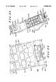
- FIG. 2is a first exploded view of the radiotelephone handset 100 of FIG. 1.
- the radiotelephone handset 100 of FIG. 2generally illustrates the housing 102, a keypad 106 and the faceplate 104.
- the housing 102contains control circuitry (not shown) providing the operational capabilities of a portable telephone such as a radiotelephone.
- the housing 102includes a plurality 124 of keypad holes, a display lens 126 and an earpiece hole 128.
- the plurality 124 of keypad holesform a part of the keypad interface 116 and permits electrical and mechanical contact between the individual keys 108 of the keypad 106 and the control circuitry contained within the housing 102.
- the display lens 126has a particular appearance and forms a part of the display interface 114 and permits viewing of and protects a display (not shown) controlled by the control circuitry within the housing 102.
- the display lens 126is affixed to the housing 102.
- the display lens 126is detachable and may be substituted with another display lens having a different particular appearance.
- the earpiece hole 128forms a part of the earpiece interface 112 and permits acoustic coupling between the user's ear and a speaker contained within the housing 102.
- the housing 102includes a front face 130 and a rear face 132.
- the front face 130preferably includes a recessed portion 134 defined by a perimeter 136.
- the front face 130further includes one or more slots 138.
- the one or more slots 138include a slot 140, slot 142, slot 144, slot 146, slot 148 and slot 150.
- the one or more slots 138includes other slots not visible in FIG. 2 arranged symmetrically with slots 140, 142, 144 and 146 on the front face 130 of the housing 102.
- the housing 102has a first end 152 and a second end 154. At the first end 152, the housing 102 preferably includes a slot 156.
- the housing 102includes an aperture 157 at the first end 152.
- the aperture 157is adapted to receive a latch pin located on the faceplate 104 for securing the faceplate 104 to the housing 102.
- the keypad 106includes a plurality of keys 108 having a distinctive key appearance.
- the keypad 106is securely attached to the housing 102 as part of the manufacturing process.
- the keypadis detachable from the housing, permitting replacement with another keypad having a different distinctive key appearance.
- the faceplate 104preferably includes a plurality 158 of keyholes, a lens aperture 160 and an ear cup 162.
- the plurality 158 of keyholesprovides tactile access to the keys 108 of the keypad 106 for the user of the radiotelephone handset 100.
- Each of the keyholes of the plurality 158 of keyholesis sized to accommodate one of the keys 108 of the keypad 106.
- the lens aperture 160is sized to accommodate the display lens 126 affixed to the housing 102. In this manner, the lens aperture 160 permits easy viewing of the display lens 126.
- the ear cup 162includes a plurality 164 of ear holes. The ear holes permit acoustic coupling between the earpiece hole 128 of the housing 102 and the user's ear.
- the ear cup 162is preferably contoured to maximize acoustic coupling.
- the faceplate 104has an outer surface 166, an inner surface 168 and a perimeter 170. Extending from the inner surface 168 along the perimeter 170, the faceplate 104 includes one or more tabs 172 including tabs 174, 176, 178, 180 and 182. Also preferably, the one or more tabs 172 includes tabs not visible in FIG. 2 arranged symmetrically with tabs 174, 176, 178 on the inner surface 168 of the faceplate 104.
- the faceplate 104has a first end 184 and a second end 186. Extending from the inner surface 168 of the faceplate 104 at the first end 184 is a tongue 188.
- the faceplate 104preferably includes a finger slot 190.
- the faceplate 104may be removable attached to the housing 102 by inserting the one or more tabs 172 into corresponding slots of the one or more slots 138 in a snap-fit connection. Similarly, the tongue 188 of the faceplate 104 may be inserted in the slot 156 at the first end of the housing 102. By engagement of the one or more tabs 172 extending from the faceplate 104 with the one or more slots 138 in the housing 102, the faceplate 104 is maintained snugly against the front face 130 of the housing 102.
- the perimeter 170 of the faceplate 104is configured to conform to the perimeter 136 of the recessed portion 134 of the front face 130 of housing 102. In this manner, the housing 102 receives the faceplate as one of a plurality of faceplates to provide a distinctive user interface appearance for the radiotelephone handset, thereby giving the radiotelephone handset one distinctive telephone appearance of a plurality of distinctive telephone appearances.
- FIG. 3shows a second exploded view of the radiotelephone handset 100 of FIG. 1.
- FIG. 3further illustrates the housing 102, the faceplate 104 and the keypad 106.
- the one or more tabs 172 arranged along the inner surface 168 of the faceplate 104are visible.
- the one or more tabs 172include tabs 174, 176, 178, 180 and 182.
- the one or more tabs 172also includes tabs 202, 204 and 206.
- the faceplate 104includes a latch pin 208 extending from the inner surface 168.
- the faceplate 104includes a post 210 located on the inner surface 168 at the first end 184.
- the post 210is a molded portion of the faceplate 104.
- the post 210includes an aperture configured to receive the latch pin 208 and securely retain the latch pin 208 by friction, adhesive or other means.
- the latch pin 208may be integrally formed with the faceplate 104, as by injection molding, or by any other appropriate method.
- the housing 102includes a battery receiving portion 212, a channel 214 and a receptacle 216.
- the radiotelephone handset 100generally includes control circuitry contained within the housing 102 which operates in response to electrical power provided by a battery (not shown).
- the housing 102is configured to securely receive the battery attached to the rear face 132 at the battery receiving portion 212.
- the battery receiving portion 212includes slide rails 218 and 220.
- the housingincludes contact apertures 222 for permitting electrical contact between the battery and the control circuitry contained within the housing.
- the receptacle 216is configured to receive a plug (not shown) which provides electrical contact to the control circuitry of the handset 100, for example, for recharging the battery or for providing operating power from an AC adapter.
- the rear face 132 of the housing 102further includes a channel 214 at the first end 152. Recessed within the channel 214 is a latch keeper 224. As will be discussed further in conjunction with FIGS. 4-7, the latch keeper 224, is configured to releasably engage the latch pin 208 to securely retain the faceplate 104 as a unitary assembly with the housing 102.
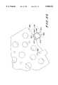
- FIG. 4shows a first detailed view of a portion of the radiotelephone handset 100 of FIG. 1.
- the channel 214is formed in the rear face 132 of the housing 102. Recessed within the channel 214 is the latch keeper 224.
- the latch keeperis preferably formed from metal or other suitably strong, rigid material.
- the latch keeper 224preferably includes a substantially flat arm 226 having a first aperture 228 and a second aperture 230 and an upright portion 229 having a third aperture 231.
- the latch pin 208extends through the aperture 157 (not shown) in the front face 130 of the housing 102.
- the first aperture 228 of the latch keeper 224is sized to receive a portion of the latch pin 208 when the latch pin extends through the aperture 157.
- the second aperture 230is contiguous with the first aperture 228 and sized to retain the portion of the latch pin 208.
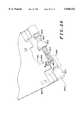
- FIG. 5is a second detailed view of a portion of the radiotelephone handset 100 of FIG. 1.
- the latch keeperis slideable between a release position illustrated in FIG. 4 and a lock position illustrated in FIG. 5.
- the latch keeper 224has been moved from the position illustrated in FIG. 4 in order to securely engage and retain the latch pin 208.
- the first aperture 228aligns with the aperture 157 in the housing 102 (FIG. 2) to receive the latch pin inserted through the aperture 157.
- the second aperture 230aligns with the aperture 157.
- the third aperture 231is configured to receive the tip of a pen, pencil or other instrument to facilitate sliding the latch keeper 224 between the lock position and the release position.
- the channel 214includes one or more retainers, such as retainer 232.
- Retainer 232retains the latch keeper 224 in the channel 214 while permitting sliding movement between the release position for releasing the latch pin 208 (FIG. 4) and the lock position for locking the latch pin 208 (FIG. 5).
- the latch pin 208 and the latch keeper 224form a latch 209. It will be understood by those skilled in the art that the latch 209 could be formed using different elements which still provide the function of securing the faceplate 104 to the housing 102.
- FIG. 6is a cross-sectional view taken along line 6-6' in FIG. 4.
- FIG. 7is a cross-sectional view taken along line 7-7' in FIG. 5.
- the latch pin 208includes a cap 234 having a seat portion 235 and a neck 236.
- the neckhas a neck diameter and the cap has a cap diameter.
- the cap diameteris larger than the neck diameter so that when the latch keeper 224 is in the latched position (FIGS. 5 and 7) the neck 236 is engaged by the second aperture 230 to retain the latch pin 208 within the latch keeper 224.
- substantially flat arm 226 of the latch keeper 224includes an arcuate portion 238.
- the arcuate portion 238is preferably slightly flexible as may be achieved if the latch keeper 224 is fabricated from a flexible material, such as thin metal.
- the arcuate portion 238engages the seat portion 235 of the cap 234 of the latch pin 208.
- the arcuate portion 238forms a bias element for asserting a bias force between the latch pin 208 and the housing 102 when the latch keeper 224 is in the lock position. This bias force serves to snugly retain the latch pin 208 and to prevent the latch keeper 224 from inadvertently sliding from the locked position to the release position (FIG. 6).
- the latch 209 formed by the latch pin 208 and the latch keeper 224operates to additionally retain the faceplate 104 to the housing 102, supplementing the mechanical connection provided by the one or more tabs 172 and the one or more slots 138.
- the latch 209is a configurable latch in that it may be moved between a release configuration and a lock configuration. In the release configuration, the faceplate 104 may be readily removed and replaced. In the lock configuration, the faceplate 104 is secured to the housing 102.
- the faceplate 104 and the keypad 106may be attached to the housing 102 at various points in time throughout the distribution chain, it is conceived that the faceplate 104 alone or in combination with the keypad 106 may be sold as a user interface kit. Such a kit would be available to the user for a specific selection at a distribution outlet, a retail store, or by mail order, thereby allowing the user to initially use a distinctive appearance or to change the faceplate and choose another distinctive appearance at a later time.
- the radiotelephone handset 400generally includes a housing 402 having a front face 401, a faceplate 404 and a keypad 406 disposed on the front face of the housing, the keypad 406 having a plurality 408 of keys.
- the handset 400includes an antenna mount 403 adapted to receive an antenna 410 permitting radio communication within a cellular network.
- the housing 402includes a front housing portion 414 and a rear housing portion 416.
- the housing 402 illustrated in FIGS. 8-9is substantially identical to the housing illustrated in FIGS. 1-7.
- the radiotelephone handset 400comprises a portable radio configured for radio communication with a remote transceiver.
- the radiotelephone handset 400includes a keypad cover 418 movable between a first position (FIG. 8) and a second position (FIG. 9).
- the keypad cover 418covers a portion of the keypad 406 in the first position and the keypad cover 418 exposes a portion of the keypad 406 in the second position.
- the keypad cover 418may be extended to cover a portion of the front housing in the first position.
- the keypad cover 418covers one of a portion of the faceplate 404 and the front housing portion in the first position.
- the radiotelephone handset 400further comprises a hinge 420 for rotational movement of the keypad cover 418 between the first position and the second position.
- the hinge 420rotatably couples the keypad cover 418 to the faceplate 404 and the keypad cover 418 and hinge 420 are integrally formed with the faceplate 404.
- the hinge 420could be located in other suitable locations, such as in a position coupling the keypad cover 418 to the front housing portion 414.
- the keypad cover 418comprises a hinged flap which covers the keys 408 of the keypad 406 in the first position.
- keypad coverssuch as those which move in a translational direction, may be substituted for the illustrated embodiment.
- the keypad cover 418provides additional user convenience not available in other radiotelephone handsets, such as the embodiment illustrated in FIG. 1. For example, a user may close the keypad cover by moving it from the second position to the first position. In the first position, the keys 408 are protected from inadvertent actuations. Also, the keys 408 are protected from water, dirt and other contaminants when the keypad cover 418 is in the first position. When the keypad cover 418 is open, or in the second position, the keypad cover 418 operates to direct sound waves from the user's mouth toward a microphone 422 located on the front face 401. The keypad cover 418 also operates to shield a portion of the user's face, including the mouth, when in the second position, thereby providing the user with a feeling of privacy when speaking during a phone call.
- the faceplate 404includes a body 428 configured for removable attachment to the housing 402 of a communication device such as the radiotelephone handset 400 and a keypad cover 418 movably coupled to the body 428.
- the keypad cover 418may be omitted from the faceplate 404 and form a separate element.
- the faceplate 404has a first end 430 and a second end 432.
- the faceplate 404further includes a hinge 420 disposed at the first end 430 of the body 428 coupling the keypad cover 418 to the faceplate 404 to provide rotational movement of the keypad cover 418 between the first position and the second position.
- the faceplate 404includes an outer surface 434 and an inner surface 436 and a perimeter 435.
- the outer surface 434defines a plurality of keyholes 438. Each keyhole is sized to receive a key 408 of the keypad 406 when the faceplate 404 and the keypad 406 are attached to the housing 402. In FIGS. 10-13, the faceplate 404 is shown with the keypad 406 engaging the faceplate 404.
- the faceplate 404preferably includes an aperture 440, an ear cup 442 and a microphone aperture 444.
- the housing 402includes a display lens 446 (FIG. 9).
- the aperture 440is sized to accommodate the display lens when the faceplate 404 is attached to the housing 402.
- the ear cup 442includes a plurality 448 of ear holes which permit acoustic coupling between earpiece hole 128 (FIG. 2) of the housing 402 and the user's ear.
- the front face 401 of the housing 402defines a recessed portion 450 and a non-recessed portion 452, separated by a perimeter 454.
- the recessed portion 450is sized and shaped to receive the faceplate 404, thereby providing a substantially flush fit between the outer surface 434 of the faceplate 404 and the non-recessed portion 452.
- the outer surface 434 of the faceplate 404defines a recessed portion 456 and a non-recessed portion 458 (FIG. 11).
- the recessed portion 456is sized to receive the keypad cover 418 when the keypad cover 418 is in the first position, thereby providing a substantially flush fit between the keypad cover 418 and the non-recessed portion 458 of the outer surface 434.
- the flush fit between the keypad cover 418 and the faceplate 404 and between the faceplate 404 and the housing 402ensure a smooth, attractive appearance. Of course, other appearances and design choices may also be accommodated.
- the faceplate 404is configured for removable attachment to the front housing portion 414.
- the faceplatehas tabs 460, 462 at the second end 432 which are insertable into corresponding slots 148, 150 of the housing 102 (FIG. 2).
- the faceplate 404preferably includes a post 464 located in the inner surface 436 and a latch pin 466 extending therefrom. The latch pin 466 is positioned to engage a latch keeper such as latch keeper 224 of the housing 402 (FIG. 3) to securely retain the faceplate on the front face 401 of the housing 402.
- the radiotelephone handsetincludes a configurable latch for releasably securing the faceplate to the housing, the configurable latch including the latch pin 466 and the latch keeper 224.
- the configurable latchmay be omitted and the faceplate 404 retained on the housing 402 by snap fitting or by other means.
- the faceplate 404may be permanently attached to the housing 402 at the time of manufacture, with the faceplate chosen to customize the appearance of the radiotelephone handset 400 when assembled with the standard housing 402.
- the radiotelephone handset 400may be provided to a user in a complete package.
- the radiotelephone handset 400includes a standard housing, such as housing 402, having a standard appearance, a keypad configured to be disposed on the front face 401 of the housing 402, and a plurality of faceplates such as faceplate 404 and faceplate 104 (FIG. 2).
- Each faceplateis configured for removable attachment to the front face of the standard housing 402 for customizing the appearance of the radiotelephone handset 400.
- At least one faceplate of the plurality of faceplates, such as faceplate 404has a keypad cover 418 movable between a first position and a second position.
- the keypad cover 418covers a portion of the keypad in the first position and exposes a portion of the keypad in the second position.
- each faceplateis identical to make them interchangeable.
- Each faceplatehas an outer perimeter 435 configured to conform to the perimeter 454 of the recessed portion 450 of the housing 402.
- the present inventionprovides a radiotelephone handset adapted to accommodate a plurality of distinctive telephone appearances.
- the handsetincludes a housing adapted to receive a faceplate as one of a plurality of faceplates to provide a distinctive user interface appearance for the handset.
- the faceplateincludes a latch pin extending from an inner surface to be engaged by a latch keeper located on the radiotelephone housing. The latch keeper allows the faceplate to be snugly retained against the housing or to be released and exchanged with another faceplate.
- a kit including the faceplate and a keypad for the radiotelephone handsetmay be separately combined and sold to provide an alternative user interface appearance for the handset.
- a radiotelephone system 1500includes a base station 1502 and a plurality of radiotelephones, such as radiotelephone 1504, radiotelephone 1506, radiotelephone 1508, radiotelephone 1510 and radiotelephone 1512.
- the radiotelephone system 1500is a cordless telephone system, cellular system or any similar wireless communication system.
- the radiotelephone system 1500includes any number of radiotelephones and the number illustrated in FIG. 15 is arbitrarily chosen to illustrate one embodiment of such a system.
- the radiotelephone system 1500is configured for radio communication between the base station 1502 and each of the plurality of radiotelephones. Radio communication occurs according to a standard protocol. Examples of such a standard protocol include the Digital European Cordless Telephone (DECT) protocol or the Personal Handy Phone system (PHS) protocol.
- DECTDigital European Cordless Telephone
- PHSPersonal Handy Phone system
- the base station 1502provides an interface between radio communication with the plurality of radiotelephones and wire line communication with a telephone network.
- the base station 1502includes a wire line interface 1514, a controller 1516, a memory 1518, a user interface 1520, a receive circuit 1522, a transmit circuit 1524, an antenna switch 1526 and an antenna 1528.
- the wire line interface 1514is coupled to an input 1530 which is configured for coupling to a telephone network.
- the wire line interface 1514provides functions such as tone generation for dual tone, multiple frequency (DTMF) dialing and detection of an incoming ringing signal from the telephone network.
- DTMFdual tone, multiple frequency
- the wire line interface 1514also communicates signals representative of speech between the telephone network and the controller 1516.
- the controller 1516controls the operation of the base station 1502.
- the user interface 1520includes a display 1532, a keypad 1534, a speaker 1536 and a microphone 1538.
- the receiver circuit 1522 and the transmitter circuit 1524provide radio communication for the base station with one or more radiotelephones of the plurality of radiotelephones.
- the base station 1502Upon reception of RF signals, the base station 1502 receives radio frequency (RF) signals through the antenna 1528.
- the antenna 1528converts the RF signals into electrical baseband signals.
- the receiver circuit 1522demodulates the electrical baseband signals, recovers the data transmitted on the RF signals and produces a serial data stream. This serial data stream is converted to clocked data and is provided to the controller 1516.
- the controller 1516formats the data into recognizable voice or information for use by the user interface 1520 or for transmission to the wire line interface 1514.
- the user interface 1520communicates the received information or voice to a user.
- the wire line interface 1514communicates the received information or voice to the telephone network.
- the controller 1516Upon transmission of radio frequency (RF) signals from the base station 1502, the controller 1516 receives user input data from the user interface 1520 and receives wire line information from the wire line interface 1514. The controller 1516 formats the information obtained from the user interface 1520 and conveys it to the transmitter circuit 1524 for conversion into modulated RF signals. The transmitter circuit 1524 conveys the RF modulated signals to the antenna 1528 for transmission to the base station 1502. The antenna switch 1526 selectively couples either the receiver circuit 1522 or the transmit circuit 1524 to the antenna 1528.
- RFradio frequency
- Each radiotelephone of the plurality of radiotelephonesincludes similar radio circuitry for communicating with the base station 1502 as well as similar mechanical construction. Structure and operation of a radiotelephone in conjunction with the base station 1502 will be described using radiotelephone 1504 as an example. However, radiotelephone 1506, radiotelephone 1508, radiotelephone 1510 and radiotelephone 1512 are preferably substantially identical to radiotelephone 1504.
- the radiotelephone 1504includes an antenna 1552, an antenna switch 1554, a receiver circuit 1556, a transmitter circuit 1558, a controller 1560, a memory 1562, a user interface 1564 and a sensor or switch 1574.
- the radiotelephone 1504Upon reception of RF signals from the base station 1502, the radiotelephone 1504 receives the RF signals through the antenna 1552.
- the antenna 1552converts the RF signals into electrical baseband signals.
- the receiver circuit 1556demodulates the electrical baseband signals, recovers the data transmitted on the RF signals and provides clocked data to the controller 1560.
- the controller 1560formats the data into recognizable voice or information for use by the user interface 1564.
- the user interface 1564communicates the received information or voice to a user.
- the user interface 1564includes a speaker 1566, a microphone 1568, a keypad 1570 and a display 1572.
- the keypad 1570includes a standard telephone keypad and optionally includes other function keys as well.
- the displayis a multiple line liquid crystal display (LCD), or any type of suitable display such as a light emitting diode (LED) display.
- the displayoptionally includes other visual indicators, such as LED indicators which selectively illuminate to provide user information.
- the user interface 1564Upon transmission of radio frequency (RF) signals from the radiotelephone 1504 to the base station 1502, the user interface 1564 transmits user input data to the controller 1560.
- the controller 1560formats the information obtained from the user interface 1564 and transmits it to the transmitter circuit 1558 for conversion into modulated RF signals.
- the transmitter circuit 1558conveys the RF modulated signals to the antenna 1552 for transmission to the base station 1502.
- the switch 1574provides a detection signal in response to detecting the presence of a keypad cover or other movable element on the faceplate, in a manner to be described below.
- the switch 1574is coupled to the controller 1560 for providing the detection signal.
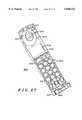
- a communication device 1600includes a housing 1602, a first faceplate 1604 and a keypad 1570.
- the housing 1602includes a first end 1606 and a second end 1608 and the housing 1602 has a front face 1610.
- the housing 1602includes a front housing portion 1612 and a rear housing portion 1614 which are mated at the time of assembly.
- the housing 1602is a standard housing having a standard appearance which is combined with other elements, such as a faceplate and keypad to provide a customized appearance.
- the keypad 1570is disposed on the front face 1610 of the housing 1602.
- the keypad 1570includes a plurality of keys 1571.
- the keys 1571have any suitable size and shape, and the shape and color and other appearance features of the keys differ on different keypads to provide a customized appearance for the communication device 1600.
- the keypadfurther includes control keys 1573 including a link key 1575.
- the link key 1575in accordance with the present invention is used to establish a radio link with a remote transceiver such as the base station 1502 (FIG. 15).
- FIG. 17illustrates the first faceplate 1604.
- the first faceplate 1604which is also referred to as an escutcheon, is configured for attachment to the front face 1610 of the housing 1602.
- the first faceplate 1604includes tabs 1616 along a perimeter 1618.
- the front face 1610 of the housing 1602defines corresponding slots.
- the tabs 1616engage the corresponding slots to retain the first faceplate 1604 on the front face 1610.
- the first faceplate 1604further includes a bottom retainer 1620 at a first end 1622 and a top tab 1624 at a second end 1626.
- the bottom retainer 1620 and the top tab 1624engage corresponding slots on the housing 1602 and assist in retaining the first faceplate 1604 on the housing 1602.
- the first faceplate 1604 and the housing 1602include other features for securing the first faceplate 1604, and other faceplates, to the housing 1602.
- the first faceplate 1604is permanently affixed to the front face 1610 at the time of manufacture.
- the first faceplate 1604is interchangeable with other faceplates.
- the communication device 1600comprises a radiotelephone configured for radio communication with a remote transceiver, such as the base station 1502 (FIG. 15).
- a remote transceiversuch as the base station 1502 (FIG. 15).
- the first faceplate 1604omits a movable element which covers a portion of the keypad 1570.
- the communication device 1600includes a second faceplate 1804.
- the second faceplate 1804is configured for attachment to the front face 1610 of the housing 1602.
- the second faceplate 1804includes a moveable element 1802.
- the movable element 1802is movable between a first position and a second position.
- the movable element 1802comprises a keypad cover which is movable between a first or closed position, shown in FIG. 19, and a second or open position shown in FIG. 18.
- the keypad covercovers a portion of the keypad 1570 in the closed position.
- the keypad covercovers all or less of the keypad, or also covers other parts of the communication device 1600, such as the display 1572.
- the movable element 1802comprises other movable features of the communication device 1600.
- FIG. 20 and FIG. 21illustrate the second faceplate 1804.
- the second faceplate 1804includes tabs 1616 along a perimeter 1618. When the second faceplate 1804 is affixed to the front face 1610, the tabs 1616 engage the corresponding slots on the housing 1602 to retain the second faceplate 1804 on the front face 1610.
- the second faceplate 1804further includes a bottom retainer 1620 at a first end 1622 and a top tab 1624 at a second end 1626. The bottom retainer 1620 and the top tab 1624 assist in retaining the second faceplate 1804 on the housing 1602.
- the communication device 1600comprises a portable radiotelephone handset provided with a plurality of faceplates, each faceplate configured for removable attachment to the front face of the standard housing 1602 for customizing appearance of the portable radiotelephone handset.
- At least one faceplatehas a keypad cover movable between a first position and a second position, the keypad cover covering a portion of the keypad in the first position and exposing the portion of the keypad in the second position.
- a faceplate for the communication device 1600is configured for attachment to the housing 1602 and is selected from the group consisting of a faceplate including a movable element which is movable between a first position and a second position and a faceplate lacking the movable element.
- the first faceplate 1604 omitting a movable elementis removably interchanged with the second faceplate 1804 including the movable element 1802.
- the housing 1602 having a standard appearanceis combined with a faceplate having a custom appearance, including or omitting a movable element.
- the communication device 1600thus is customized by the manufacturer at the time of manufacturer or by the user at a subsequent time.
- the communication deviceincludes a sensor such as switch 1574 disposed within the housing 1602.
- the sensordetects attachment of a faceplate to the front face 1610 of the housing 1602 and provides a detection signal in response to detection of a faceplate such as second faceplate 1804 and a movable element such as movable element 1802 disposed on the housing 1602.
- the sensoris any type of mechanical or electrical sensor which provides a detection signal which may be interpreted by the controller 1560 as indicative of the presence of a faceplate with a movable element.
- the detection signalis a binary electrical signal produced by a switch.
- the detection signalhas a first state when the first faceplate 1604 omitting a movable element is present and a second state when the second faceplate 1804 including a movable element is present.
- the sensordetects if a movable element such as the keypad cover is present and detects a position of the keypad cover.
- the binary detection signalhas a first state to indicate, for example, presence of the keypad cover and a closed position of the keypad cover, as illustrated in FIG. 19.
- the binary detection signalhas a second state to indicate absence of the keypad cover, as illustrated in FIG. 16, or an open position of the keypad cover, if present, as illustrated in FIG. 18.
- the sensorprovides the detection signal to the controller 1560.
- the controller 1560is responsive to the detection signal for varying the operation of the communication device accordingly.
- the controller 1560is coupled to the sensor and implements a first set of functions in response to a first state of the detection signal and a second set of functions in response to a second state of the detection signal.
- the detection signalindicates that the movable element 1802 is present and in a first position, such as a keypad cover closed position.
- the controller 1560responds to this detection signal by maintaining the communication device in a standby condition, awaiting reception of incoming RF signals from a remote transceiver such as the base station 1502 to initiate a radio link with the remote transceiver.
- the detection signalindicates that the movable element is present and in a second position, such as a keypad cover open position. The controller 1560 responds to this detection signal by awaiting user input.
- the controller 1560responds by initiating operation of the communication device 1600 to initiate a radio link with the remote transceiver and to await user input from the keypad 1570 as the user dials a phone number. If the detection signal has changed state from keypad cover open to keypad cover closed, the controller 1560 responds by terminating the radio link with the remote transceiver and returning the communication device 1600 to the standby condition. While other functions are available, this example illustrates operation of the communication device 1600 with an active keypad cover.
- the detection signalindicates that a faceplate such as faceplate 1604 omitting a movable element is present.
- the controller 1560waits to detect a predetermined user input from the keypad 1570.
- the usermay initiate operation of the communication device by first depressing the link key 1575.
- the controller 1560detects the keypress of the link key 1575 of the keypad 1570 and initiates a radio link with the remote transceiver.
- the usersubsequently depresses other keys 1571 of the keypad 1570 to dial a telephone call, and eventually depresses the link key 1575 again to terminate the telephone call and terminate the radio link with the remote transceiver.
- operation of the communication deviceincludes detecting at the controller 1560 presence of a keypad cover on the faceplate in response to the detection signal. If a keypad cover is present, the controller 1560 detects a position of the keypad cover. If no keypad cover is present, the controller 1560 awaits a user input from the keypad 1570. Operation also includes moving the keypad cover from a closed position to an open position, detecting movement of the keypad cover, and in response, initiating a communication link to a remote transceiver.
- the communication device 1600may be operated with either a faceplate having a keypad cover or a faceplate omitting a cover. Further, such faceplates are interchangeable, and either may be attached to the standard housing 1602 to customize the appearance and the operation of the communication device 1600.
- the first faceplate 1604 and the second faceplate 1804are illustrated assembled with the keypad 1570.
- the keypadis permanently or detachably assembled with the housing 1602.
- the keypad 1570is sold separately along with the first faceplate 1604 or the second faceplate 1604 as a user interface kit for customizing the appearance of the communication device.
- FIG. 22is a rear perspective view of the second faceplate 1804.
- the second faceplate 1804includes a body 1830 and a hinge 1832 coupling the movable element 1802 or keypad cover and the body 1830.
- the hinge 1832provides rotational movement of the keypad cover between the first position or closed position and the second position or open position.
- the body 1830defines apertures 1834 for the keys 1571 and control keys 1573 and the link key 1575 of the keypad 1570.
- the body 1830further defines an earpiece 1835 for positioning near the speaker 1566 (FIG. 15).
- the earpiece 1835includes holes 1836 which permit sound to pass from the speaker 1566 to the user's ear.
- the body 1830further defines a display aperture 1838 to permit viewing of the display 1572 which is disposed on the front face of the housing 1602.
- the bottom retainer 1620includes a first retainer 1621 and a second retainer 1623.
- the body 1830further defines a cavity 1839 between first retainer 1621 and second retainer 1623
- the hinge 1832is at the first end 1622 of the second faceplate 1804 for rotatably moving the keypad cover between the first position and the second position.
- FIG. 23is a detailed view of a portion of the second faceplate 1804.
- FIG. 24is a cross sectional view taken along line A-A' in FIG. 19 showing a portion of the communication device.
- the hinge 1832includes a hinge pin 1840, a cam 1842, a spring 1844 and a cam journal 1846.
- the second retainer 1623defines a keyway for receiving the hinge pin 1840.
- the received end of the hinge pin 1840is sized to fit the keyway.
- the keyway and the received end of the hinge pin 1840are shaped irregularly or eccentrically so that the hinge pin is maintained in the keyway without rotating when the movable element 1802 is moved or rotated.
- the hinge pin 1840is integrally formed with the second retainer 1623 and the rest of the body 1830, as by injection molding a plastic part.
- the cam journal 1846has an end sized to extend through the first retainer 421 and to be received by a hinge knuckle 1852 of the movable element 1802. Retention of the end of the cam journal in the hinge knuckle 1852 is illustrated in FIG. 24.
- the movable element 1802is rotatable about an axis 1854 defined by the cam journal 1846 and the hinge pin 1840. As the movable element 1802 is rotated, the cam journal 1846 rotates about the axis 1854.
- the hinge pin 1840has a cam-shaped portion 1850.
- the cam 1842is annular and sized to rotatingly surround a portion of the hinge pin 1840.
- the spring 1844urges the cam 1842 against the cam-shaped portion 1850.
- a first detent positionis the first or closed position of the movable element 1802 and a second detent position is the second or open position of the movable element 1802.
- the communication device 1600includes a printed circuit board (PCB) 1860 suitable to be disposed within the housing 1602.
- FIG. 26is a perspective view of a portion of the communication device showing the PCB 1860 in conjunction with the hinge 1832.
- the PCB 1860defines apertures 1862 for soldering circuit elements such as the controller 1560 (FIG. 15) to the PCB 1860.
- the PCB 1860includes an extension 1864 proximate the first end 1606 of the housing of the communication device 1600 when the PCB 1860 is assembled in the housing 1602.
- the switch 1574is located on the extension 1864 and is electrically coupled to the controller 1560 using conventional printed circuit board wiring techniques.
- the switch 1574is a normally open switch.
- the switch 1574includes a body 1866, an actuation arm 1868, a first electrical contact 1870 and a second electrical contact 1872. When the communication device 1600 is assembled, the first electrical contact 1870 and the second electrical contact 1872 are electrically coupled to the controller 1560.
- the actuation arm 1868extends from a recess defined in a side 1874 of the body 1866.
- the actuation arm 1868is movable between an open position and a closed position. In the open position, the actuation arm 1868 extends substantially fully from the body 1866, as illustrated in FIG. 24. This is the normally open position of the switch 1574, which includes a spring or other bias element urging the actuation arm 1868 out of the body to the open position.
- the actuation arm 1868In the closed position, the actuation arm 1868 is depressed partly or wholly into the recess.
- the first electrical contact 1870 and the second electrical contact 1872are electrically coupled together.
- the switchprovides the detection signal to the controller in a first state when the actuation arm 1868 is in the closed position and provides the detection signal in a second state when the actuation arm is in the open position.
- the switch 1574lies in a plane 1880 which is generally parallel to the PCB 1860.
- the switch 1574 and the axis 1854 of rotation of the hingeare preferably coplanar to permit the hinge 1832 to actuate the actuation arm as the hinge 1832 is rotated about the axis 1854.
- the cam journal 1846defines a profiled recess 1882.
- the actuation arm 1868extends into the profiled recess 1882.
- the cam journal 1846engages the actuation arm 1868 and depresses the actuation arm into the recess, moving the actuation arm 1868 from its open position to its closed position.
- the profiled recess 1882thus acts as an actuator for the switch 1574.
- the profiled recess 1882is preferably profiled to permit smooth actuation of the switch 1574, without catching on the actuation arm 1868 or without wearing unduly from use over time. While the actuation arm 1868 is shown being actuated by the profiled recess 1882, the actuation may be provided by any suitable structure. For example, in an alternative embodiment, a rotating element of the hinge 1832 includes a protrusion positioned to engage the actuation arm 1868 of the switch 1574. If a sensor other than the switch is used for detecting the presence of the second faceplate 1804, another type of actuator is provided.
- a plunger actuatorIn a plunger actuator, a plunger or other protrusion extends from the inner surface of the keypad cover and, as the keypad cover is closed, the plunger extends through an opening in the front housing of the communication device to engage and actuate a switch located within the housing on a printed circuit board.
- a plunger-type actuatoruse of the profiled recess 1882 defined by the cam journal 1846 permits switching to occur at any position of the movable element 1802. The switch point can be changed by merely modifying the cam profile.
- a plunger-type actuatorrequires an aperture in the front housing to engage the switch on the printed circuit board within.
- the hinge configuration in accordance with the present inventionuses up less space than a plunger-type actuator, which is important in modern portable communication devices, where small size is valued by many customers.
- FIG. 27is a rear perspective view of the first faceplate of FIG. 17.
- FIG. 28is a detail view of a portion of the first faceplate 1604.
- the first faceplate 1604includes a fixed actuator 1890 positioned to retain the actuation arm 1868 in the open position while the first faceplate 1604 is attached to the front face 1610 of the housing 1602.
- the switchprovides the detection signal in only the second state when the first faceplate 1604, which omits a movable element, is present.
- the controller 1560implements only a second set of functions, such as establishing a radio link with the remote transceiver only in response to a keypress of a key of the keypad 1570.
- the additional functions provided by the presence of the movable element 1802are not available in this configuration.
- This aspect of the present inventionmay be used by the manufacturer to establish product tiering and distinguish individual models.
- the present inventionprovides a communication device such as a portable radiotelephone which features interchangeable faceplates. Interchangeability permits customization of the appearance of the communication device.
- the faceplatesinclude a faceplate which includes a movable element such as a keypad cover and a faceplate which omits a keypad cover.
- a sensordetects the presence of the movable element, as well as the position of the movable element so that the operation of the communication device may be varied accordingly.
- the communication devicemay be customized in performance as well as appearance by providing an active keypad cover.
- the components which permit the keypad cover to move, such as the hinge pin, cam, cam journal and spring,are self-contained and remain with the second faceplate and keypad cover to minimize the risk of loss during changeover of the faceplate.
- the keypad covermay be movably attached to the housing rather than the second faceplate as illustrated herein.
- the keypad coverrather than being rotatably coupled, may slide across the face of the communication device or move in any other suitable manner. It is therefore intended in the appended claims to cover all such changes and modifications which fall within the true spirit and scope of the invention.
Landscapes
- Engineering & Computer Science (AREA)
- Signal Processing (AREA)
- Human Computer Interaction (AREA)
- Computer Networks & Wireless Communication (AREA)
- Telephone Set Structure (AREA)
Abstract
Description
Claims (33)
Priority Applications (1)
| Application Number | Priority Date | Filing Date | Title |
|---|---|---|---|
| US08/759,503US5848152A (en) | 1995-09-26 | 1996-12-04 | Communication device having interchangeable faceplates and active keypad cover |
Applications Claiming Priority (5)
| Application Number | Priority Date | Filing Date | Title |
|---|---|---|---|
| US53397795A | 1995-09-26 | 1995-09-26 | |
| US29/046,799USD388080S (en) | 1995-10-18 | 1995-10-18 | Portable telephone housing |
| US29/055,807USD388078S (en) | 1996-05-02 | 1996-05-02 | Portable telephone housing |
| US08/742,379US5982881A (en) | 1995-09-26 | 1996-11-01 | Radiotelephone handset having a faceplate to accommodate a plurality of distinctive telephone appearances |
| US08/759,503US5848152A (en) | 1995-09-26 | 1996-12-04 | Communication device having interchangeable faceplates and active keypad cover |
Related Parent Applications (2)
| Application Number | Title | Priority Date | Filing Date |
|---|---|---|---|
| US29055807Continuation-In-Part | 1996-05-02 | ||
| US08/742,379Continuation-In-PartUS5982881A (en) | 1995-09-26 | 1996-11-01 | Radiotelephone handset having a faceplate to accommodate a plurality of distinctive telephone appearances |
Publications (1)
| Publication Number | Publication Date |
|---|---|
| US5848152Atrue US5848152A (en) | 1998-12-08 |
Family
ID=27489097
Family Applications (1)
| Application Number | Title | Priority Date | Filing Date |
|---|---|---|---|
| US08/759,503Expired - LifetimeUS5848152A (en) | 1995-09-26 | 1996-12-04 | Communication device having interchangeable faceplates and active keypad cover |
Country Status (1)
| Country | Link |
|---|---|
| US (1) | US5848152A (en) |
Cited By (193)
| Publication number | Priority date | Publication date | Assignee | Title |
|---|---|---|---|---|
| USD413884S (en)* | 1998-06-15 | 1999-09-14 | Sanyo Electric Co., Ltd. | Portable telephone |
| US5956398A (en)* | 1997-07-11 | 1999-09-21 | Ericsson Inc. | Telephone switching mechanism |
| USD415149S (en)* | 1997-07-18 | 1999-10-12 | Nokia Mobile Phones Limited | Handset |
| USD415489S (en) | 1999-01-05 | 1999-10-19 | Kun Chou Co., Ltd. | Handheld telephone |
| USD420678S (en)* | 1999-02-12 | 2000-02-15 | Nokia Mobile Phones Limited | Keypad |
| USD420680S (en)* | 1999-02-12 | 2000-02-15 | Nokia Mobile Phones Limited | Front cover for a telephone handset |
| US6026283A (en)* | 1997-12-05 | 2000-02-15 | Ericsson Inc. | Electrically conductive keypad lightguides |
| USD421022S (en)* | 1999-02-12 | 2000-02-22 | Nokia Mobile Phones Limited | Display and key array for a telephone handset |
| USD421004S (en)* | 1999-02-12 | 2000-02-22 | Nokia Mobile Phones Limited | Handset |
| USD421023S (en)* | 1999-02-12 | 2000-02-22 | Nokia Mobile Phones Limited | Cover for a telephone handset |
| USD421019S (en)* | 1999-02-12 | 2000-02-22 | Nokia Mobile Phones Limited | Keypad |
| USD421442S (en)* | 1999-02-12 | 2000-03-07 | Nokia Mobile Phones Limited | Front cover for a telephone handset |
| USD421435S (en)* | 1999-05-24 | 2000-03-07 | Motorola, Inc. | Housing for a two-way communication device |
| USD421985S (en)* | 1999-02-08 | 2000-03-28 | Ericsson Inc. | Radiotelephone |
| USD421984S (en)* | 1999-02-08 | 2000-03-28 | Ericsson Inc. | Radiotelephone |
| USD422585S (en)* | 1999-08-24 | 2000-04-11 | Motorola, Inc. | Housing for a two-way portable communication device |
| USD423015S (en)* | 1999-02-12 | 2000-04-18 | Nokia Mobile Phones Ltd. | Display and key array for a telephone handset |
| USD425073S (en)* | 1999-04-28 | 2000-05-16 | Nokia Mobile Phones Limited | Cover for a telephone handset |
| US6065187A (en)* | 1998-05-14 | 2000-05-23 | Motorola, Inc. | Hinge assembly |
| USD426819S (en)* | 1999-02-08 | 2000-06-20 | Ericsson Inc. | Radiotelephone |
| USD426830S (en) | 1999-08-09 | 2000-06-20 | Nokia Mobile Phones, Limited | Cover for a telephone handset |
| USD428001S (en)* | 1999-08-09 | 2000-07-11 | Nokia Mobile Phones, Ltd. | Front cover for a telephone handset |
| USD428401S (en)* | 1999-08-09 | 2000-07-18 | Nokia Mobile Phones, Limited | Handset |
| USD428879S (en)* | 1999-06-14 | 2000-08-01 | Nokia Mobile Phones, Ltd. | Keypad |
| USD429240S (en)* | 1999-08-09 | 2000-08-08 | Nokia Mobile Phones, Ltd. | Keypad for a telephone handset |
| USD429241S (en)* | 1999-02-08 | 2000-08-08 | Ericsson Inc. | Radiotelephone face |
| USD432509S (en)* | 1999-10-08 | 2000-10-24 | Motorola, Inc. | Portable radio communication device |
| US6141831A (en)* | 1997-12-09 | 2000-11-07 | Cema Technologies, Inc. | Bistable hinge mechanism |
| USD433670S (en)* | 1999-10-08 | 2000-11-14 | Motorola, Inc. | Portable radio communication device |
| USD434016S (en)* | 1999-11-05 | 2000-11-21 | Telefonaktiebolaget Lm Ericsson | Portable telephone |
| USD434410S (en)* | 1999-06-14 | 2000-11-28 | Nokia Mobile Phones Limited | Cover for a telephone handset |
| USD434744S (en)* | 2000-06-21 | 2000-12-05 | Gvc Corporation | Mobile phone |
| USD434743S (en)* | 2000-06-21 | 2000-12-05 | Gvc Corporation | Mobile phone |
| USD434741S (en)* | 1999-04-10 | 2000-12-05 | Hyundai Electronics Industries Co., Ltd. | Portable telephone |
| USD435027S (en)* | 2000-08-04 | 2000-12-12 | Motorola, Inc. | Housing for portable communications device |
| US6175990B1 (en)* | 1997-10-08 | 2001-01-23 | Katoh Electrical Machinery Co., Ltd. | Hinge device |
| USD436938S1 (en) | 1999-12-04 | 2001-01-30 | Hyundai Electronics Industries Co., Ltd. | Portable telephone |
| USD436949S1 (en) | 1999-06-14 | 2001-01-30 | Nokia Mobile Phones Limited | Cover for a telephone handset |
| USD437838S1 (en) | 2000-07-26 | 2001-02-20 | Kun Chou Co., Ltd. | Handheld telephone |
| US6194874B1 (en)* | 1999-03-17 | 2001-02-27 | Telefonaktiebolaget Lm Ericsson (Publ) | System and method for maintenance charging of battery cells |
| USD439230S1 (en) | 2000-05-12 | 2001-03-20 | Motorola, Inc. | Portable communication device |
| US6212366B1 (en)* | 1998-03-02 | 2001-04-03 | Motorola, Inc. | Housing assembly for a selective call receiver |
| GB2355126A (en)* | 1999-10-08 | 2001-04-11 | Nokia Mobile Phones Ltd | Mobile telephone user interface working in dependence of the nature of a releasable housing |
| US6246887B1 (en)* | 1996-02-14 | 2001-06-12 | Robert Bosch Gmbh | Appliance with indicating device |
| WO2001056258A1 (en)* | 2000-01-28 | 2001-08-02 | Siemens Aktiengesellschaft | Apparatus having an exchangeable housing part |
| USD446200S1 (en) | 2001-01-05 | 2001-08-07 | Senao International Co., Ltd. | Handset |
| USD446786S1 (en) | 2000-02-03 | 2001-08-21 | Mitsubishi Denki Kabushiki Kaisha | Portion of portable telephone |
| WO2001069894A1 (en)* | 2000-03-15 | 2001-09-20 | Fiero Richard A | Portable device comprising keypad and screen |
| USD448379S1 (en) | 2000-09-01 | 2001-09-25 | Audio Design Associates, Inc. | Keypad |
| USD448759S1 (en) | 2000-07-26 | 2001-10-02 | Nokia Mobile Phones Ltd. | Keypad for a handset |
| WO2001080532A1 (en)* | 2000-04-13 | 2001-10-25 | Siemens Aktiengesellschaft | Unit provided with a display device |
| USD449830S1 (en) | 2000-08-23 | 2001-10-30 | Nokia Mobile Phones, Ltd | Display and key array for a handset |
| GB2362071A (en)* | 2000-05-05 | 2001-11-07 | Nokia Mobile Phones Ltd | A detachable cover for a portable radio communication device with identity means which when sensed, changes the operation of the device |
| USD450316S1 (en) | 2000-08-23 | 2001-11-13 | Nokia Mobile Phones, Ltd | Front cover for a handset |
| WO2001086922A1 (en)* | 2000-05-05 | 2001-11-15 | Nokia Corporation | Removable housing cover for a portable radio communication device |
| USD450689S1 (en) | 2000-08-23 | 2001-11-20 | Nokia Mobile Phones, Ltd | Keypad for a handset |
| USD450671S1 (en) | 2000-08-23 | 2001-11-20 | Nokia Mobile Phones, Ltd | Handset |
| USD451503S1 (en) | 2000-08-23 | 2001-12-04 | Nokia Mobile Phones, Ltd | Display and key array for a handset |
| USD451502S1 (en) | 2000-08-23 | 2001-12-04 | Nokia Mobile Phones, Ltd | Key matrix for a handset |
| USD451914S1 (en) | 2000-08-23 | 2001-12-11 | Nokia Mobile Phones Ltd. | Front cover for a handset |
| USD452235S1 (en) | 2000-08-23 | 2001-12-18 | Nokia Mobile Phones Ltd. | Front cover for a handset |
| US6345097B1 (en)* | 1998-12-07 | 2002-02-05 | Qualcomm Incorporated | Cam retainer for flip-style portable phone |
| US6347218B1 (en) | 1996-02-28 | 2002-02-12 | Nokia Mobile Phones Limited | Electronic device with housing supplement |
| USD454341S1 (en) | 2000-12-29 | 2002-03-12 | Nokia Mobile Phones Ltd. | Keypad for a handset |
| USD454549S1 (en) | 2000-08-23 | 2002-03-19 | Nokia Mobile Phones, Ltd. | Handset |
| USD454865S1 (en) | 2000-08-23 | 2002-03-26 | Nokia Mobile Phones Ltd. | Key matrix for a handset |
| US20020039890A1 (en)* | 2000-08-08 | 2002-04-04 | Lg Electronics Inc. | Mobile telephone body |
| USD455421S1 (en) | 2001-03-15 | 2002-04-09 | Nokia Mobile Phones Ltd. | Key array for a handset |
| US20020042291A1 (en)* | 2000-10-11 | 2002-04-11 | Markku Lahteenmaki | Communication device |
| US6375026B1 (en)* | 1997-11-28 | 2002-04-23 | Nokia Mobile Phones Ltd. | Radiotelephone |
| USD456375S1 (en) | 2000-12-29 | 2002-04-30 | Noki Mobile Phones Limited | Handset |
| USD456393S1 (en) | 2001-03-19 | 2002-04-30 | Motorola, Inc. | Radiotelephone interchangeable lens |
| USD457519S1 (en) | 2000-08-23 | 2002-05-21 | Nokia Mobile Phones, Ltd. | Key matrix for a handset |
| USD457879S1 (en) | 2000-08-23 | 2002-05-28 | Nokia Mobile Phones, Ltd. | Display and key array for a handset |
| GB2375693A (en)* | 2001-05-14 | 2002-11-20 | Innovision Res & Tech Plc | Replaceable fascia for a portable communications device |
| US20020193136A1 (en)* | 2001-06-19 | 2002-12-19 | Heikki Halkosaari | User changeable mobile phone cover |
| US20030000030A1 (en)* | 2001-06-29 | 2003-01-02 | Unilever Home & Personal Care Usa, Division Of Conopco. Inc. | Toothbrush cover |
| US20030008677A1 (en)* | 2001-07-07 | 2003-01-09 | Samsung Electronics Co., Ltd. | Replaceable sliding cover unit for folder in folder-type portable phone |
| USD469069S1 (en) | 2001-10-31 | 2003-01-21 | Motorola, Inc. | Portable communication device |
| US20030017848A1 (en)* | 2001-07-17 | 2003-01-23 | Engstrom G. Eric | Personalizing electronic devices and smart covering |
| DE10131611C1 (en)* | 2001-06-29 | 2003-01-23 | Siemens Ag | Forming external shape of electronic device, especially mobile communications device, involves filling holder chamber with deformable medium, deforming to predetermined shape |
| US20030017839A1 (en)* | 2001-07-17 | 2003-01-23 | Mager Gary N. | Interchangeable covering with keys for personalizing mobile electronic communication devices |
| WO2003009485A1 (en)* | 2001-07-17 | 2003-01-30 | Wildseed, Ltd. | Interchangeable covering with keys for personalizing mobile electronic communication devices |
| FR2828366A1 (en)* | 2001-08-01 | 2003-02-07 | Sagem | Different mode use mobile telephone having body with electronic card/contacts and removable covers/push buttons providing normal/games telephone operating modes. |
| USD470117S1 (en) | 2002-04-04 | 2003-02-11 | Nokia Corporation | Handset |
| USD471546S1 (en) | 2002-03-05 | 2003-03-11 | Nokia Corporation | Display area and key array for a handset |
| USD471905S1 (en) | 2002-04-04 | 2003-03-18 | Nokia Corporation | Front cover for a handset |
| USD472548S1 (en) | 2002-03-15 | 2003-04-01 | Nokia Corporation | Display and function key area for a handset |
| US20030078014A1 (en)* | 2001-10-24 | 2003-04-24 | Seppo Salminen | User exchangeable mobile phone keypad |
| USD474167S1 (en) | 2002-03-05 | 2003-05-06 | Nokia Corporation | Handset |
| USD474459S1 (en) | 2002-03-05 | 2003-05-13 | Nokia Corporation | Key array for a handset |
| USD474455S1 (en) | 2002-03-15 | 2003-05-13 | Nokia Corporation | Handset |
| USD474463S1 (en) | 2002-03-05 | 2003-05-13 | Nokia Corporation | Display area and key array for a handset |
| USD474756S1 (en) | 2002-03-05 | 2003-05-20 | Nokia Corporation | Handset |
| US20030100276A1 (en)* | 2001-11-27 | 2003-05-29 | Samsung Electronics Co., Ltd. | Replaceable sub-housing and interchangeable mobile telephone terminal using the same to be used both as flip-type terminal and bar-type terminal |
| USD475704S1 (en) | 2002-03-15 | 2003-06-10 | Nokia Corporation | Front cover for a handset |
| USD475997S1 (en) | 2002-02-14 | 2003-06-17 | Nokia Corporation | Keypad for a handset |
| US6594472B1 (en)* | 1999-02-12 | 2003-07-15 | Nokia Mobile Phones Ltd. | Exchangeable radiotelephone covers |
| US20030134613A1 (en)* | 2002-01-11 | 2003-07-17 | Latto Antonio T. | Removable customizable inserts and faceplate for electronic devices |
| WO2003067539A1 (en)* | 2002-02-04 | 2003-08-14 | Nokia Corporation | Electronic device with cover inclduing a radio frequency identification module |
| US20030153282A1 (en)* | 2002-02-08 | 2003-08-14 | Benq Corporation | Mobile phone with replaceable key assemblies |
| US6614905B1 (en)* | 1999-02-12 | 2003-09-02 | Nokia Mobile Phones Limited | Support structure for a keypad |
| EP1345390A1 (en)* | 2002-03-13 | 2003-09-17 | Agere Systems Limited | Flip-cover sensor for keypad |
| US6633241B2 (en)* | 1999-12-28 | 2003-10-14 | Nokia Mobile Phones Ltd. | Capacitively coupled keypad structure |
| US20040018863A1 (en)* | 2001-05-17 | 2004-01-29 | Engstrom G. Eric | Personalization of mobile electronic devices using smart accessory covers |
| USD488152S1 (en) | 2002-11-04 | 2004-04-06 | Nokia Corporation | Front cover for a handset |
| US20040109560A1 (en)* | 2000-12-29 | 2004-06-10 | Frank Nuovo | Method of producing a telephone device |
| US20040140028A1 (en)* | 2002-06-21 | 2004-07-22 | Clark Dan Warren | Protective shield for a patient control device |
| US6771981B1 (en) | 2000-08-02 | 2004-08-03 | Nokia Mobile Phones Ltd. | Electronic device cover with embedded radio frequency (RF) transponder and methods of using same |
| US6778226B1 (en)* | 2000-10-11 | 2004-08-17 | Koninklijke Philips Electronics N.V. | Device cabinet with dynamically controlled appearance |
| US20040203999A1 (en)* | 2002-05-06 | 2004-10-14 | Ming-Ching Liang | Mobile phone key |
| US20040203514A1 (en)* | 2002-06-21 | 2004-10-14 | Yung-Fa Cheng | Mobile phone with detachable covers |
| US20040203499A1 (en)* | 2002-03-01 | 2004-10-14 | Pekka Kostiainen | Functional cover for use with a wireless terminal |
| US20040248626A1 (en)* | 2003-06-05 | 2004-12-09 | Yung-Fa Cheng | Housing of electronic product |
| US20040262180A1 (en)* | 2003-06-27 | 2004-12-30 | Qin Shui Yuan | Enclosure for portable electronic device having pivotable panel handle |
| US20040261220A1 (en)* | 2003-06-09 | 2004-12-30 | Lowry David A | Bistable hinge with dampening mechanism |
| US20040263117A1 (en)* | 2003-06-30 | 2004-12-30 | Eduard Kogan | Battery pack with built in communication port |
| US20050009588A1 (en)* | 2003-07-11 | 2005-01-13 | Qin Shui Yuan | Replaceable panel device for a handset |
| US20050013434A1 (en)* | 2003-07-19 | 2005-01-20 | Qin Shui Yuan | Replaceable panel device for a handset |
| US20050017068A1 (en)* | 1995-02-15 | 2005-01-27 | Zalewski Thomas W. | System and method of making payments using an electronic device cover with embedded transponder |
| US20050026643A1 (en)* | 2001-05-14 | 2005-02-03 | White Andrew David | Electrical devices |
| US20050037717A1 (en)* | 2003-08-15 | 2005-02-17 | Oin Shui Yuan | Latching assembly for a removabable cover of a wireless communication device |
| US20050036293A1 (en)* | 2001-12-18 | 2005-02-17 | Axel Kohnke | Removable housing cover for a portable radio communication device |
| FR2863799A1 (en)* | 2003-12-15 | 2005-06-17 | Cit Alcatel | COMMUNICATION TERMINAL HAVING A PERSONALIZABLE FRONT PANEL |
| US20050141210A1 (en)* | 2003-12-26 | 2005-06-30 | Liu Ji K. | Latching assembly for a removable panel of a portable electronic device |
| US20050139683A1 (en)* | 2003-12-26 | 2005-06-30 | Curitel Communications, Inc. | Communication terminal equipped with a replaceable cover and method of changing themes of communication terminal using the same |
| US20050170872A1 (en)* | 2004-01-30 | 2005-08-04 | Nokia Corporation | Function specific interchangeable cover piece for a mobile communication device |
| US20050180118A1 (en)* | 2004-02-17 | 2005-08-18 | Fih Co., Ltd | Latching assembly for a removable cover of a portable electronic device |
| US20050183876A1 (en)* | 2004-02-20 | 2005-08-25 | Fih Co., Ltd | Latching assembly for a removable cover of a portable electronic device |
| US20050192064A1 (en)* | 2004-02-27 | 2005-09-01 | Thomas Paul A. | Exchangeable keymat |
| US20050271200A1 (en)* | 2004-06-02 | 2005-12-08 | Fih Co.,Ltd | Latching assembly for a removable cover of a portable electronic device |
| EP1640848A1 (en)* | 2004-09-20 | 2006-03-29 | VAC Corporation | Tablet PC with interchangeable housing type |
| US7068995B1 (en) | 2003-01-13 | 2006-06-27 | Sprint Spectrum L.P. | System and method for affinity marketing in a wireless network |
| US20060160560A1 (en)* | 2003-06-12 | 2006-07-20 | Michael Josenhans | Mobile communication device cover and method for its operation |
| US20060211498A1 (en)* | 2005-03-18 | 2006-09-21 | Vincent Higgins | Information display faceplate for a video game controller |
| US20060255936A1 (en)* | 2005-05-11 | 2006-11-16 | Graco Children's Products Inc. | Baby monitor system |
| US20070167128A1 (en)* | 2006-01-17 | 2007-07-19 | Popowitz Jeffrey P | Ventilation register system |
| EP1386407A4 (en)* | 2001-04-04 | 2007-08-15 | Motorola Inc | Rotational mechanism for a wireless communication device |
| US7272445B2 (en)* | 2003-10-02 | 2007-09-18 | Medtronic, Inc. | Medical device programmer with faceplate |
| US20070243911A1 (en)* | 2004-11-24 | 2007-10-18 | Matsushita Electric Industrial Co., Ltd. | Mobile Terminal |
| US7368537B2 (en) | 2003-07-15 | 2008-05-06 | Id Biomedical Corporation Of Quebec | Subunit vaccine against respiratory syncytial virus infection |
| US20080220834A1 (en)* | 2003-10-14 | 2008-09-11 | Sentinal Gardens Pty Ltd. | Protective Shroud |
| EP1471716A3 (en)* | 2003-04-14 | 2008-10-08 | Microsoft Corporation | Protective case for electronics in a mobile device |
| US20090075706A1 (en)* | 2007-09-17 | 2009-03-19 | Chi Mei Communication Systems, Inc. | Housing assembly for portable electronic device |
| US20090133219A1 (en)* | 2006-03-02 | 2009-05-28 | Southco, Inc. | Drop-in damped hinge module |
| US20090163241A1 (en)* | 2006-07-10 | 2009-06-25 | Aria Enterprises, Inc. | Configurable modular multi-function communication device |
| WO2009089393A1 (en)* | 2008-01-10 | 2009-07-16 | Aria Enterprises, Inc. | Customizable modular multi-function communication device |
| US7775355B1 (en) | 2008-11-13 | 2010-08-17 | Hood Richard W | Decorative portable computer cover |
| US20110071368A1 (en)* | 2009-09-21 | 2011-03-24 | Nellcor Puritan Bennett Llc | Medical Device Interface Customization Systems And Methods |
| US20110073456A1 (en)* | 2009-09-28 | 2011-03-31 | Chao Chen | Key assembly for an electronic device having one-piece keycaps and multi-touch preventing supports |
| US20110073454A1 (en)* | 2009-09-28 | 2011-03-31 | Research In Motion Limited | key assembly for an electronic device having a multi-character keycap |
| US20120061118A1 (en)* | 2010-04-23 | 2012-03-15 | Psion Inc. | Replaceable keypad bezel |
| US20120101551A1 (en)* | 2010-10-25 | 2012-04-26 | Boston Scientific Neuromodulation Corporation | External Controller For an Implantable Medical Device Formed Using a Sub-Assembly |
| TWI381789B (en)* | 2007-10-12 | 2013-01-01 | Chi Mei Comm Systems Inc | Housing of portable electronic device |
| US8638556B2 (en) | 2010-02-15 | 2014-01-28 | Blackberry Limited | Electronic device including a front bezel operable to secure the device together |
| US20140293521A1 (en)* | 2013-03-28 | 2014-10-02 | Brother Kogyo Kabushiki Kaisha | Storage Container |
| US8909307B2 (en) | 2011-12-29 | 2014-12-09 | Elwha Llc | Customized hardware selection for a mobile phone |
| US20140372124A1 (en)* | 2013-06-13 | 2014-12-18 | Schneider Electric Industries Sas | Human-machine dialogue device |
| US20150304467A1 (en)* | 2014-04-16 | 2015-10-22 | Samsung Electronics Co., Ltd. | Antifungal cover and electronic device including the same |
| WO2016180927A1 (en)* | 2015-05-13 | 2016-11-17 | Lumigon A/S | Wireless communications device |
| US9544707B2 (en) | 2014-02-06 | 2017-01-10 | Sonos, Inc. | Audio output balancing |
| US9549258B2 (en) | 2014-02-06 | 2017-01-17 | Sonos, Inc. | Audio output balancing |
| US9553959B2 (en) | 2011-12-29 | 2017-01-24 | Elwha Llc | Customized hardware selection for a mobile phone |
| US9658820B2 (en) | 2003-07-28 | 2017-05-23 | Sonos, Inc. | Resuming synchronous playback of content |
| US9681223B2 (en) | 2011-04-18 | 2017-06-13 | Sonos, Inc. | Smart line-in processing in a group |
| US9729115B2 (en) | 2012-04-27 | 2017-08-08 | Sonos, Inc. | Intelligently increasing the sound level of player |
| US9734242B2 (en) | 2003-07-28 | 2017-08-15 | Sonos, Inc. | Systems and methods for synchronizing operations among a plurality of independently clocked digital data processing devices that independently source digital data |
| US9748646B2 (en) | 2011-07-19 | 2017-08-29 | Sonos, Inc. | Configuration based on speaker orientation |
| US9749760B2 (en) | 2006-09-12 | 2017-08-29 | Sonos, Inc. | Updating zone configuration in a multi-zone media system |
| US9756424B2 (en) | 2006-09-12 | 2017-09-05 | Sonos, Inc. | Multi-channel pairing in a media system |
| US9766853B2 (en) | 2006-09-12 | 2017-09-19 | Sonos, Inc. | Pair volume control |
| US9787550B2 (en) | 2004-06-05 | 2017-10-10 | Sonos, Inc. | Establishing a secure wireless network with a minimum human intervention |
| US9977561B2 (en) | 2004-04-01 | 2018-05-22 | Sonos, Inc. | Systems, methods, apparatus, and articles of manufacture to provide guest access |
| US10031716B2 (en) | 2013-09-30 | 2018-07-24 | Sonos, Inc. | Enabling components of a playback device |
| US10061379B2 (en) | 2004-05-15 | 2018-08-28 | Sonos, Inc. | Power increase based on packet type |
| US10306364B2 (en) | 2012-09-28 | 2019-05-28 | Sonos, Inc. | Audio processing adjustments for playback devices based on determined characteristics of audio content |
| US10359987B2 (en) | 2003-07-28 | 2019-07-23 | Sonos, Inc. | Adjusting volume levels |
| US20190253886A1 (en)* | 2015-10-13 | 2019-08-15 | Confivox Inc. | Portable Device Accessory |
| US10613817B2 (en) | 2003-07-28 | 2020-04-07 | Sonos, Inc. | Method and apparatus for displaying a list of tracks scheduled for playback by a synchrony group |
| US11106425B2 (en) | 2003-07-28 | 2021-08-31 | Sonos, Inc. | Synchronizing operations among a plurality of independently clocked digital data processing devices |
| US11106424B2 (en) | 2003-07-28 | 2021-08-31 | Sonos, Inc. | Synchronizing operations among a plurality of independently clocked digital data processing devices |
| US11220066B2 (en)* | 2016-10-03 | 2022-01-11 | Altec Industries, Inc. | Spacer for use in precision bonding applications that provides enhanced shear strength |
| US11265652B2 (en) | 2011-01-25 | 2022-03-01 | Sonos, Inc. | Playback device pairing |
| US11294618B2 (en) | 2003-07-28 | 2022-04-05 | Sonos, Inc. | Media player system |
| US11403062B2 (en) | 2015-06-11 | 2022-08-02 | Sonos, Inc. | Multiple groupings in a playback system |
| US11429343B2 (en) | 2011-01-25 | 2022-08-30 | Sonos, Inc. | Stereo playback configuration and control |
| US11481182B2 (en) | 2016-10-17 | 2022-10-25 | Sonos, Inc. | Room association based on name |
| US11650784B2 (en) | 2003-07-28 | 2023-05-16 | Sonos, Inc. | Adjusting volume levels |
| US11894975B2 (en) | 2004-06-05 | 2024-02-06 | Sonos, Inc. | Playback device connection |
| US11995374B2 (en) | 2016-01-05 | 2024-05-28 | Sonos, Inc. | Multiple-device setup |
| US12155527B2 (en) | 2011-12-30 | 2024-11-26 | Sonos, Inc. | Playback devices and bonded zones |
| US12167216B2 (en) | 2006-09-12 | 2024-12-10 | Sonos, Inc. | Playback device pairing |
| US12245009B2 (en) | 2019-07-22 | 2025-03-04 | D&M Holdings Inc. | Wireless audio system, wireless speaker, and group joining method for wireless speaker |
Citations (14)
| Publication number | Priority date | Publication date | Assignee | Title |
|---|---|---|---|---|
| US3838229A (en)* | 1973-04-16 | 1974-09-24 | Bell Northern Research Ltd | Telephone sets and removable covers therefore |
| US4124785A (en)* | 1976-02-23 | 1978-11-07 | Bell Telephone Laboratories, Incorporated | Telephone set |
| US4292481A (en)* | 1975-07-16 | 1981-09-29 | Barnes Wayne R | Decorative applique and decorative faceplate assembly for push-button telephones |
| US4433216A (en)* | 1982-03-12 | 1984-02-21 | Northern Telecom Limited | Faceplate assembly for telecommunications terminals and other terminals |
| US4582966A (en)* | 1983-11-28 | 1986-04-15 | Sutton Bernard S | Tele disc guard |
| USD300742S (en) | 1987-09-11 | 1989-04-18 | Motorola, Inc. | Housing for a portable telephone or similar article |
| US4845772A (en)* | 1988-06-13 | 1989-07-04 | Motorola, Inc. | Portable radiotelephone with control switch disabling |
| USD309901S (en) | 1989-01-03 | 1990-08-14 | Kapow, Inc. | Telephone faceplate |
| US5086463A (en)* | 1989-10-02 | 1992-02-04 | Vesely Kevin T | Vandal-resistant communications station |
| US5117073A (en)* | 1991-04-02 | 1992-05-26 | Motorola, Inc. | Control signal initiator responsive to a hinge position |
| US5175759A (en)* | 1989-11-20 | 1992-12-29 | Metroka Michael P | Communications device with movable element control interface |
| US5202912A (en)* | 1991-09-09 | 1993-04-13 | Motorola, Inc. | Method and apparatus for providing telepoint to telepoint calling between pager equipped handsets |
| US5235636A (en)* | 1990-08-07 | 1993-08-10 | Fujitsu Limited | Portable telephone set housing having an illuminated switch panel |
| US5373556A (en)* | 1992-12-28 | 1994-12-13 | Motorola, Inc. | Quick connect housing coupling and method |
- 1996
- 1996-12-04USUS08/759,503patent/US5848152A/ennot_activeExpired - Lifetime
Patent Citations (14)
| Publication number | Priority date | Publication date | Assignee | Title |
|---|---|---|---|---|
| US3838229A (en)* | 1973-04-16 | 1974-09-24 | Bell Northern Research Ltd | Telephone sets and removable covers therefore |
| US4292481A (en)* | 1975-07-16 | 1981-09-29 | Barnes Wayne R | Decorative applique and decorative faceplate assembly for push-button telephones |
| US4124785A (en)* | 1976-02-23 | 1978-11-07 | Bell Telephone Laboratories, Incorporated | Telephone set |
| US4433216A (en)* | 1982-03-12 | 1984-02-21 | Northern Telecom Limited | Faceplate assembly for telecommunications terminals and other terminals |
| US4582966A (en)* | 1983-11-28 | 1986-04-15 | Sutton Bernard S | Tele disc guard |
| USD300742S (en) | 1987-09-11 | 1989-04-18 | Motorola, Inc. | Housing for a portable telephone or similar article |
| US4845772A (en)* | 1988-06-13 | 1989-07-04 | Motorola, Inc. | Portable radiotelephone with control switch disabling |
| USD309901S (en) | 1989-01-03 | 1990-08-14 | Kapow, Inc. | Telephone faceplate |
| US5086463A (en)* | 1989-10-02 | 1992-02-04 | Vesely Kevin T | Vandal-resistant communications station |
| US5175759A (en)* | 1989-11-20 | 1992-12-29 | Metroka Michael P | Communications device with movable element control interface |
| US5235636A (en)* | 1990-08-07 | 1993-08-10 | Fujitsu Limited | Portable telephone set housing having an illuminated switch panel |
| US5117073A (en)* | 1991-04-02 | 1992-05-26 | Motorola, Inc. | Control signal initiator responsive to a hinge position |
| US5202912A (en)* | 1991-09-09 | 1993-04-13 | Motorola, Inc. | Method and apparatus for providing telepoint to telepoint calling between pager equipped handsets |
| US5373556A (en)* | 1992-12-28 | 1994-12-13 | Motorola, Inc. | Quick connect housing coupling and method |
Non-Patent Citations (2)
| Title |
|---|
| Mobile Office Magazine s Cellular Buyers Guide , pp. 53, 56, 58 and 59.* |
| Mobile Office Magazine's "Cellular Buyers' Guide", pp. 53, 56, 58 and 59. |
Cited By (412)
| Publication number | Priority date | Publication date | Assignee | Title |
|---|---|---|---|---|
| US20050017068A1 (en)* | 1995-02-15 | 2005-01-27 | Zalewski Thomas W. | System and method of making payments using an electronic device cover with embedded transponder |
| US7155199B2 (en) | 1995-02-15 | 2006-12-26 | Nokia Mobile Phones Limited | System and method of making payments using an electronic device cover with embedded transponder |
| US6246887B1 (en)* | 1996-02-14 | 2001-06-12 | Robert Bosch Gmbh | Appliance with indicating device |
| US6487397B2 (en) | 1996-02-28 | 2002-11-26 | Nokia Mobile Phones Ltd. | Electronic device with housing supplement |
| US6347218B1 (en) | 1996-02-28 | 2002-02-12 | Nokia Mobile Phones Limited | Electronic device with housing supplement |
| US6978123B2 (en) | 1996-02-28 | 2005-12-20 | Nokia Mobile Phones Ltd. | Electronic device with housing supplement |
| US5956398A (en)* | 1997-07-11 | 1999-09-21 | Ericsson Inc. | Telephone switching mechanism |
| USD415149S (en)* | 1997-07-18 | 1999-10-12 | Nokia Mobile Phones Limited | Handset |
| US6175990B1 (en)* | 1997-10-08 | 2001-01-23 | Katoh Electrical Machinery Co., Ltd. | Hinge device |
| US6375026B1 (en)* | 1997-11-28 | 2002-04-23 | Nokia Mobile Phones Ltd. | Radiotelephone |
| US6026283A (en)* | 1997-12-05 | 2000-02-15 | Ericsson Inc. | Electrically conductive keypad lightguides |
| US6141831A (en)* | 1997-12-09 | 2000-11-07 | Cema Technologies, Inc. | Bistable hinge mechanism |
| US6212366B1 (en)* | 1998-03-02 | 2001-04-03 | Motorola, Inc. | Housing assembly for a selective call receiver |
| US6065187A (en)* | 1998-05-14 | 2000-05-23 | Motorola, Inc. | Hinge assembly |
| USD413884S (en)* | 1998-06-15 | 1999-09-14 | Sanyo Electric Co., Ltd. | Portable telephone |
| US6345097B1 (en)* | 1998-12-07 | 2002-02-05 | Qualcomm Incorporated | Cam retainer for flip-style portable phone |
| USD415489S (en) | 1999-01-05 | 1999-10-19 | Kun Chou Co., Ltd. | Handheld telephone |
| USD429241S (en)* | 1999-02-08 | 2000-08-08 | Ericsson Inc. | Radiotelephone face |
| USD421985S (en)* | 1999-02-08 | 2000-03-28 | Ericsson Inc. | Radiotelephone |
| USD426819S (en)* | 1999-02-08 | 2000-06-20 | Ericsson Inc. | Radiotelephone |
| USD421984S (en)* | 1999-02-08 | 2000-03-28 | Ericsson Inc. | Radiotelephone |
| USD421019S (en)* | 1999-02-12 | 2000-02-22 | Nokia Mobile Phones Limited | Keypad |
| USD421442S (en)* | 1999-02-12 | 2000-03-07 | Nokia Mobile Phones Limited | Front cover for a telephone handset |
| USD421022S (en)* | 1999-02-12 | 2000-02-22 | Nokia Mobile Phones Limited | Display and key array for a telephone handset |
| USD421004S (en)* | 1999-02-12 | 2000-02-22 | Nokia Mobile Phones Limited | Handset |
| USD421023S (en)* | 1999-02-12 | 2000-02-22 | Nokia Mobile Phones Limited | Cover for a telephone handset |
| US6614905B1 (en)* | 1999-02-12 | 2003-09-02 | Nokia Mobile Phones Limited | Support structure for a keypad |
| USD423015S (en)* | 1999-02-12 | 2000-04-18 | Nokia Mobile Phones Ltd. | Display and key array for a telephone handset |
| US6594472B1 (en)* | 1999-02-12 | 2003-07-15 | Nokia Mobile Phones Ltd. | Exchangeable radiotelephone covers |
| USD420678S (en)* | 1999-02-12 | 2000-02-15 | Nokia Mobile Phones Limited | Keypad |
| USD420680S (en)* | 1999-02-12 | 2000-02-15 | Nokia Mobile Phones Limited | Front cover for a telephone handset |
| US6194874B1 (en)* | 1999-03-17 | 2001-02-27 | Telefonaktiebolaget Lm Ericsson (Publ) | System and method for maintenance charging of battery cells |
| USD449588S1 (en) | 1999-04-10 | 2001-10-23 | Hyundai Electronics Industries Co., Ltd. | Portable telephone |
| USD434741S (en)* | 1999-04-10 | 2000-12-05 | Hyundai Electronics Industries Co., Ltd. | Portable telephone |
| USD425073S (en)* | 1999-04-28 | 2000-05-16 | Nokia Mobile Phones Limited | Cover for a telephone handset |
| USD421435S (en)* | 1999-05-24 | 2000-03-07 | Motorola, Inc. | Housing for a two-way communication device |
| USD434410S (en)* | 1999-06-14 | 2000-11-28 | Nokia Mobile Phones Limited | Cover for a telephone handset |
| USD436949S1 (en) | 1999-06-14 | 2001-01-30 | Nokia Mobile Phones Limited | Cover for a telephone handset |
| USD428879S (en)* | 1999-06-14 | 2000-08-01 | Nokia Mobile Phones, Ltd. | Keypad |
| USD426830S (en) | 1999-08-09 | 2000-06-20 | Nokia Mobile Phones, Limited | Cover for a telephone handset |
| USD428001S (en)* | 1999-08-09 | 2000-07-11 | Nokia Mobile Phones, Ltd. | Front cover for a telephone handset |
| USD428401S (en)* | 1999-08-09 | 2000-07-18 | Nokia Mobile Phones, Limited | Handset |
| USD429240S (en)* | 1999-08-09 | 2000-08-08 | Nokia Mobile Phones, Ltd. | Keypad for a telephone handset |
| USD422585S (en)* | 1999-08-24 | 2000-04-11 | Motorola, Inc. | Housing for a two-way portable communication device |
| GB2355126B (en)* | 1999-10-08 | 2004-02-11 | Nokia Mobile Phones Ltd | Communication terminal having exchangeable parts |
| USD433670S (en)* | 1999-10-08 | 2000-11-14 | Motorola, Inc. | Portable radio communication device |
| USD432509S (en)* | 1999-10-08 | 2000-10-24 | Motorola, Inc. | Portable radio communication device |
| EP1091540A3 (en)* | 1999-10-08 | 2001-11-14 | Nokia Mobile Phones Ltd. | Communication terminal having exchangeable parts |
| EP1091540A2 (en) | 1999-10-08 | 2001-04-11 | Nokia Mobile Phones Ltd. | Communication terminal having exchangeable parts |
| GB2355126A (en)* | 1999-10-08 | 2001-04-11 | Nokia Mobile Phones Ltd | Mobile telephone user interface working in dependence of the nature of a releasable housing |
| EP1091540B1 (en)* | 1999-10-08 | 2008-08-13 | Nokia Corporation | Communication terminal having exchangeable parts |
| US7092519B1 (en) | 1999-10-08 | 2006-08-15 | Nokia Mobile Phones, Ltd. | Communication terminal having exchangeable parts |
| USD434016S (en)* | 1999-11-05 | 2000-11-21 | Telefonaktiebolaget Lm Ericsson | Portable telephone |
| USD436938S1 (en) | 1999-12-04 | 2001-01-30 | Hyundai Electronics Industries Co., Ltd. | Portable telephone |
| US6633241B2 (en)* | 1999-12-28 | 2003-10-14 | Nokia Mobile Phones Ltd. | Capacitively coupled keypad structure |
| WO2001056258A1 (en)* | 2000-01-28 | 2001-08-02 | Siemens Aktiengesellschaft | Apparatus having an exchangeable housing part |
| US20030012003A1 (en)* | 2000-01-28 | 2003-01-16 | Stefan Bischof | Apparatus having an exchangeable housing part |
| USD446786S1 (en) | 2000-02-03 | 2001-08-21 | Mitsubishi Denki Kabushiki Kaisha | Portion of portable telephone |
| US6373501B1 (en)* | 2000-03-15 | 2002-04-16 | Richard A. Fiero | Portable device comprising keypad and screen |
| WO2001069894A1 (en)* | 2000-03-15 | 2001-09-20 | Fiero Richard A | Portable device comprising keypad and screen |
| US20040110526A1 (en)* | 2000-04-13 | 2004-06-10 | Rainer Volland | Apparatus having a display device |
| WO2001080532A1 (en)* | 2000-04-13 | 2001-10-25 | Siemens Aktiengesellschaft | Unit provided with a display device |
| WO2001086922A1 (en)* | 2000-05-05 | 2001-11-15 | Nokia Corporation | Removable housing cover for a portable radio communication device |
| GB2362071A (en)* | 2000-05-05 | 2001-11-07 | Nokia Mobile Phones Ltd | A detachable cover for a portable radio communication device with identity means which when sensed, changes the operation of the device |
| US6898283B2 (en)* | 2000-05-05 | 2005-05-24 | Nokia Mobile Phones Ltd. | Exchangable housing cover for a portable radio communication device |
| US20020037738A1 (en)* | 2000-05-05 | 2002-03-28 | Mark Wycherley | Removable housing cover for a portable radio communication device |
| US20020030103A1 (en)* | 2000-05-05 | 2002-03-14 | Mark Wycherley | Removable housing cover for a portable radio communication device |
| GB2362071B (en)* | 2000-05-05 | 2004-07-14 | Nokia Mobile Phones Ltd | Removable housing cover for a portable radio communication device |
| USD439230S1 (en) | 2000-05-12 | 2001-03-20 | Motorola, Inc. | Portable communication device |
| USD434744S (en)* | 2000-06-21 | 2000-12-05 | Gvc Corporation | Mobile phone |
| USD434743S (en)* | 2000-06-21 | 2000-12-05 | Gvc Corporation | Mobile phone |
| USD437838S1 (en) | 2000-07-26 | 2001-02-20 | Kun Chou Co., Ltd. | Handheld telephone |
| USD448759S1 (en) | 2000-07-26 | 2001-10-02 | Nokia Mobile Phones Ltd. | Keypad for a handset |
| US6771981B1 (en) | 2000-08-02 | 2004-08-03 | Nokia Mobile Phones Ltd. | Electronic device cover with embedded radio frequency (RF) transponder and methods of using same |
| USD435027S (en)* | 2000-08-04 | 2000-12-12 | Motorola, Inc. | Housing for portable communications device |
| US20020039890A1 (en)* | 2000-08-08 | 2002-04-04 | Lg Electronics Inc. | Mobile telephone body |
| USD449830S1 (en) | 2000-08-23 | 2001-10-30 | Nokia Mobile Phones, Ltd | Display and key array for a handset |
| USD453928S1 (en) | 2000-08-23 | 2002-02-26 | Nokia Mobile Phones, Ltd. | Keypad for a handset |
| USD450689S1 (en) | 2000-08-23 | 2001-11-20 | Nokia Mobile Phones, Ltd | Keypad for a handset |
| USD456376S1 (en) | 2000-08-23 | 2002-04-30 | Nokia Mobile Phones, Ltd. | Handset |
| USD455736S1 (en) | 2000-08-23 | 2002-04-16 | Nokia Mobile Phones, Ltd. | Keypad for a handset |
| USD454865S1 (en) | 2000-08-23 | 2002-03-26 | Nokia Mobile Phones Ltd. | Key matrix for a handset |
| USD457519S1 (en) | 2000-08-23 | 2002-05-21 | Nokia Mobile Phones, Ltd. | Key matrix for a handset |
| USD457879S1 (en) | 2000-08-23 | 2002-05-28 | Nokia Mobile Phones, Ltd. | Display and key array for a handset |
| USD454549S1 (en) | 2000-08-23 | 2002-03-19 | Nokia Mobile Phones, Ltd. | Handset |
| USD455739S1 (en) | 2000-08-23 | 2002-04-16 | Nokia Mobile Phones Limited | Front cover for a handset |
| USD450316S1 (en) | 2000-08-23 | 2001-11-13 | Nokia Mobile Phones, Ltd | Front cover for a handset |
| USD452235S1 (en) | 2000-08-23 | 2001-12-18 | Nokia Mobile Phones Ltd. | Front cover for a handset |
| USD451914S1 (en) | 2000-08-23 | 2001-12-11 | Nokia Mobile Phones Ltd. | Front cover for a handset |
| USD451502S1 (en) | 2000-08-23 | 2001-12-04 | Nokia Mobile Phones, Ltd | Key matrix for a handset |
| USD451503S1 (en) | 2000-08-23 | 2001-12-04 | Nokia Mobile Phones, Ltd | Display and key array for a handset |
| USD450671S1 (en) | 2000-08-23 | 2001-11-20 | Nokia Mobile Phones, Ltd | Handset |
| USD448379S1 (en) | 2000-09-01 | 2001-09-25 | Audio Design Associates, Inc. | Keypad |
| US20020042291A1 (en)* | 2000-10-11 | 2002-04-11 | Markku Lahteenmaki | Communication device |
| US7469154B2 (en) | 2000-10-11 | 2008-12-23 | Nokia Corporation | Communication Device |
| EP1198110A3 (en)* | 2000-10-11 | 2004-01-21 | Nokia Corporation | Communication device |
| US6778226B1 (en)* | 2000-10-11 | 2004-08-17 | Koninklijke Philips Electronics N.V. | Device cabinet with dynamically controlled appearance |
| USD456375S1 (en) | 2000-12-29 | 2002-04-30 | Noki Mobile Phones Limited | Handset |
| US20040109560A1 (en)* | 2000-12-29 | 2004-06-10 | Frank Nuovo | Method of producing a telephone device |
| USD454341S1 (en) | 2000-12-29 | 2002-03-12 | Nokia Mobile Phones Ltd. | Keypad for a handset |
| USD446200S1 (en) | 2001-01-05 | 2001-08-07 | Senao International Co., Ltd. | Handset |
| USD455421S1 (en) | 2001-03-15 | 2002-04-09 | Nokia Mobile Phones Ltd. | Key array for a handset |
| USD472894S1 (en) | 2001-03-19 | 2003-04-08 | Motorola, Inc. | Interchangeable lens for radiotelephones and similar articles |
| USD456393S1 (en) | 2001-03-19 | 2002-04-30 | Motorola, Inc. | Radiotelephone interchangeable lens |
| EP1386407A4 (en)* | 2001-04-04 | 2007-08-15 | Motorola Inc | Rotational mechanism for a wireless communication device |
| GB2375693A (en)* | 2001-05-14 | 2002-11-20 | Innovision Res & Tech Plc | Replaceable fascia for a portable communications device |
| US20050026643A1 (en)* | 2001-05-14 | 2005-02-03 | White Andrew David | Electrical devices |
| US20050269403A1 (en)* | 2001-05-14 | 2005-12-08 | Innovision Research & Technology Plc | Electrical devices |
| US7392059B2 (en) | 2001-05-14 | 2008-06-24 | Innovision Research & Technology Plc | Electrical devices |
| US20050266899A1 (en)* | 2001-05-14 | 2005-12-01 | Innovision Research & Technology Plc | Electrical devices |
| US7313422B2 (en) | 2001-05-14 | 2007-12-25 | Innovision Research & Technology Plc | Electrical devices |
| US20070001005A1 (en)* | 2001-05-14 | 2007-01-04 | Innovision Research & Technology Plc | Electrical devices |
| US7248892B2 (en) | 2001-05-14 | 2007-07-24 | Innovision Research & Technology Plc | Electrical devices |
| US7376439B2 (en) | 2001-05-14 | 2008-05-20 | Innovision Research & Technology Plc | Electrical devices |
| US7373170B2 (en) | 2001-05-14 | 2008-05-13 | Innovision Research & Technology Plc | Electrical devices |
| US20040018863A1 (en)* | 2001-05-17 | 2004-01-29 | Engstrom G. Eric | Personalization of mobile electronic devices using smart accessory covers |
| US20020193136A1 (en)* | 2001-06-19 | 2002-12-19 | Heikki Halkosaari | User changeable mobile phone cover |
| US7069063B2 (en)* | 2001-06-19 | 2006-06-27 | Nokia Mobile Phones Limited | User changeable mobile phone cover |
| US20030000030A1 (en)* | 2001-06-29 | 2003-01-02 | Unilever Home & Personal Care Usa, Division Of Conopco. Inc. | Toothbrush cover |
| US6779216B2 (en) | 2001-06-29 | 2004-08-24 | Unilever Home & Personal Care Usa, A Division Of Conopco, Inc. | Toothbrush cover |
| DE10131611C1 (en)* | 2001-06-29 | 2003-01-23 | Siemens Ag | Forming external shape of electronic device, especially mobile communications device, involves filling holder chamber with deformable medium, deforming to predetermined shape |
| US7197345B2 (en)* | 2001-07-07 | 2007-03-27 | Samsung Electronics Co., Ltd. | Replaceable sliding cover unit for folder in folder-type portable phone |
| US20030008677A1 (en)* | 2001-07-07 | 2003-01-09 | Samsung Electronics Co., Ltd. | Replaceable sliding cover unit for folder in folder-type portable phone |
| WO2003009485A1 (en)* | 2001-07-17 | 2003-01-30 | Wildseed, Ltd. | Interchangeable covering with keys for personalizing mobile electronic communication devices |
| US20030017848A1 (en)* | 2001-07-17 | 2003-01-23 | Engstrom G. Eric | Personalizing electronic devices and smart covering |
| US7095986B2 (en)* | 2001-07-17 | 2006-08-22 | Wildseed Ltd. | Interchangeable covering with keys for personalizing mobile electronic communication devices |
| US20030017839A1 (en)* | 2001-07-17 | 2003-01-23 | Mager Gary N. | Interchangeable covering with keys for personalizing mobile electronic communication devices |
| FR2828366A1 (en)* | 2001-08-01 | 2003-02-07 | Sagem | Different mode use mobile telephone having body with electronic card/contacts and removable covers/push buttons providing normal/games telephone operating modes. |
| US7269449B2 (en) | 2001-10-24 | 2007-09-11 | Nokia Corporation | User exchangeable mobile phone keypad |
| US20030078014A1 (en)* | 2001-10-24 | 2003-04-24 | Seppo Salminen | User exchangeable mobile phone keypad |
| WO2003036922A3 (en)* | 2001-10-24 | 2003-09-18 | Nokia Corp | User exchangeable mobile phone keypad |
| USD469069S1 (en) | 2001-10-31 | 2003-01-21 | Motorola, Inc. | Portable communication device |
| US20030100276A1 (en)* | 2001-11-27 | 2003-05-29 | Samsung Electronics Co., Ltd. | Replaceable sub-housing and interchangeable mobile telephone terminal using the same to be used both as flip-type terminal and bar-type terminal |
| KR100454969B1 (en)* | 2001-11-27 | 2004-11-06 | 삼성전자주식회사 | Exterior-replacable sub-housing and flip-type/bar-type combination mobile phone therewith |
| US7092680B2 (en) | 2001-11-27 | 2006-08-15 | Samsung Electronics Co., Ltd. | Replaceable sub-housing and interchangeable mobile telephone terminal using the same to be used both as flip-type terminal and bar-type terminal |
| EP1315360A3 (en)* | 2001-11-27 | 2004-06-09 | Samsung Electronics Co., Ltd. | Replaceable sub-housing and interchangeable mobile telephone terminal using the same to be used both as flip-type terminal and bar-type terminal |
| US20090034210A1 (en)* | 2001-12-18 | 2009-02-05 | Nokia Corporation | Removable housing cover for a portable radio communication device |
| US7755905B2 (en) | 2001-12-18 | 2010-07-13 | Nokia Corporation | Removable housing cover for a portable radio communication device |
| US20050036293A1 (en)* | 2001-12-18 | 2005-02-17 | Axel Kohnke | Removable housing cover for a portable radio communication device |
| US7206618B2 (en)* | 2002-01-11 | 2007-04-17 | Intel Corporation | Removable customizable inserts and faceplate for electronic devices |
| US20030134613A1 (en)* | 2002-01-11 | 2003-07-17 | Latto Antonio T. | Removable customizable inserts and faceplate for electronic devices |
| US20070161421A1 (en)* | 2002-01-11 | 2007-07-12 | Latto Antonio T | Removalbe customizable inserts and faceplate for electronic devices |
| US20110065487A1 (en)* | 2002-01-11 | 2011-03-17 | Latto Antonio T | User interchangeable ornamental portions of electronic devices |
| US8532720B2 (en)* | 2002-01-11 | 2013-09-10 | Intel Corporation | User interchangeable ornamental portions of electronic devices |
| US10375844B2 (en) | 2002-01-11 | 2019-08-06 | Intel Corporation | User interchangeable ornamental portions of electronic devices |
| WO2003067539A1 (en)* | 2002-02-04 | 2003-08-14 | Nokia Corporation | Electronic device with cover inclduing a radio frequency identification module |
| US6816083B2 (en) | 2002-02-04 | 2004-11-09 | Nokia Corporation | Electronic device with cover including a radio frequency indentification module |
| US20030153282A1 (en)* | 2002-02-08 | 2003-08-14 | Benq Corporation | Mobile phone with replaceable key assemblies |
| USD475997S1 (en) | 2002-02-14 | 2003-06-17 | Nokia Corporation | Keypad for a handset |
| US7421269B2 (en)* | 2002-03-01 | 2008-09-02 | Nokia Corporation | Functional cover for use with a wireless terminal |
| US20040203499A1 (en)* | 2002-03-01 | 2004-10-14 | Pekka Kostiainen | Functional cover for use with a wireless terminal |
| USD474459S1 (en) | 2002-03-05 | 2003-05-13 | Nokia Corporation | Key array for a handset |
| USD474756S1 (en) | 2002-03-05 | 2003-05-20 | Nokia Corporation | Handset |
| USD474463S1 (en) | 2002-03-05 | 2003-05-13 | Nokia Corporation | Display area and key array for a handset |
| USD471546S1 (en) | 2002-03-05 | 2003-03-11 | Nokia Corporation | Display area and key array for a handset |
| USD474167S1 (en) | 2002-03-05 | 2003-05-06 | Nokia Corporation | Handset |
| US6894239B2 (en) | 2002-03-13 | 2005-05-17 | Agere Systems Inc. | Flip-cover sensor for keypad |
| EP1345390A1 (en)* | 2002-03-13 | 2003-09-17 | Agere Systems Limited | Flip-cover sensor for keypad |
| US20040011634A1 (en)* | 2002-03-13 | 2004-01-22 | Agere Systems Inc. | Flip-cover sensor for keypad |
| USD472548S1 (en) | 2002-03-15 | 2003-04-01 | Nokia Corporation | Display and function key area for a handset |
| USD474455S1 (en) | 2002-03-15 | 2003-05-13 | Nokia Corporation | Handset |
| USD475704S1 (en) | 2002-03-15 | 2003-06-10 | Nokia Corporation | Front cover for a handset |
| USD471905S1 (en) | 2002-04-04 | 2003-03-18 | Nokia Corporation | Front cover for a handset |
| USD470117S1 (en) | 2002-04-04 | 2003-02-11 | Nokia Corporation | Handset |
| US20040203999A1 (en)* | 2002-05-06 | 2004-10-14 | Ming-Ching Liang | Mobile phone key |
| US7011213B2 (en) | 2002-06-21 | 2006-03-14 | Biotronics | Protective shield for a patient control device |
| US20040203514A1 (en)* | 2002-06-21 | 2004-10-14 | Yung-Fa Cheng | Mobile phone with detachable covers |
| US20040140028A1 (en)* | 2002-06-21 | 2004-07-22 | Clark Dan Warren | Protective shield for a patient control device |
| USD488152S1 (en) | 2002-11-04 | 2004-04-06 | Nokia Corporation | Front cover for a handset |
| US7068995B1 (en) | 2003-01-13 | 2006-06-27 | Sprint Spectrum L.P. | System and method for affinity marketing in a wireless network |
| EP1471716A3 (en)* | 2003-04-14 | 2008-10-08 | Microsoft Corporation | Protective case for electronics in a mobile device |
| US7031760B2 (en)* | 2003-06-05 | 2006-04-18 | Quanta Computer, Inc. | Housing of electronic product |
| US20040248626A1 (en)* | 2003-06-05 | 2004-12-09 | Yung-Fa Cheng | Housing of electronic product |
| US7065834B2 (en) | 2003-06-09 | 2006-06-27 | Southco, Inc. | Bistable hinge with dampening mechanism |
| US20040261220A1 (en)* | 2003-06-09 | 2004-12-30 | Lowry David A | Bistable hinge with dampening mechanism |
| US20060160560A1 (en)* | 2003-06-12 | 2006-07-20 | Michael Josenhans | Mobile communication device cover and method for its operation |
| US7536199B2 (en)* | 2003-06-12 | 2009-05-19 | Nokia Corporation | Mobile communication device cover and method for its operation |
| US20040262180A1 (en)* | 2003-06-27 | 2004-12-30 | Qin Shui Yuan | Enclosure for portable electronic device having pivotable panel handle |
| US20060119317A1 (en)* | 2003-06-30 | 2006-06-08 | Symbol Technologies, Inc. | Battery pack with built in communication port |
| US7176655B2 (en) | 2003-06-30 | 2007-02-13 | Symbol Technologies, Inc. | Battery pack with built in communication port |
| US20040263117A1 (en)* | 2003-06-30 | 2004-12-30 | Eduard Kogan | Battery pack with built in communication port |
| US20070126397A1 (en)* | 2003-06-30 | 2007-06-07 | Symbol Technologies, Inc. | Battery pack with built in communication port |
| US7019420B2 (en)* | 2003-06-30 | 2006-03-28 | Symbol Technologies, Inc. | Battery pack with built in communication port |
| US7768232B2 (en) | 2003-06-30 | 2010-08-03 | Symbol Technologies, Inc. | Battery pack with built in communication port |
| US8169188B2 (en) | 2003-06-30 | 2012-05-01 | Symbol Technologies, Inc. | Battery pack with built in communication port |
| US7149559B2 (en)* | 2003-07-11 | 2006-12-12 | Hon Hai Precision Ind. Co., Ltd. | Replaceable panel device for a handset |
| US20050009588A1 (en)* | 2003-07-11 | 2005-01-13 | Qin Shui Yuan | Replaceable panel device for a handset |
| US7368537B2 (en) | 2003-07-15 | 2008-05-06 | Id Biomedical Corporation Of Quebec | Subunit vaccine against respiratory syncytial virus infection |
| US20050013434A1 (en)* | 2003-07-19 | 2005-01-20 | Qin Shui Yuan | Replaceable panel device for a handset |
| US7333607B2 (en)* | 2003-07-19 | 2008-02-19 | Shenzhen Futaihong Precision Industry Co., Ltd. | Replaceable panel device for a handset |
| US11200025B2 (en) | 2003-07-28 | 2021-12-14 | Sonos, Inc. | Playback device |
| US10175930B2 (en) | 2003-07-28 | 2019-01-08 | Sonos, Inc. | Method and apparatus for playback by a synchrony group |
| US10031715B2 (en) | 2003-07-28 | 2018-07-24 | Sonos, Inc. | Method and apparatus for dynamic master device switching in a synchrony group |
| US11625221B2 (en) | 2003-07-28 | 2023-04-11 | Sonos, Inc | Synchronizing playback by media playback devices |
| US10120638B2 (en) | 2003-07-28 | 2018-11-06 | Sonos, Inc. | Synchronizing operations among a plurality of independently clocked digital data processing devices |
| US9778900B2 (en) | 2003-07-28 | 2017-10-03 | Sonos, Inc. | Causing a device to join a synchrony group |
| US9778898B2 (en) | 2003-07-28 | 2017-10-03 | Sonos, Inc. | Resynchronization of playback devices |
| US11635935B2 (en) | 2003-07-28 | 2023-04-25 | Sonos, Inc. | Adjusting volume levels |
| US9778897B2 (en) | 2003-07-28 | 2017-10-03 | Sonos, Inc. | Ceasing playback among a plurality of playback devices |
| US11650784B2 (en) | 2003-07-28 | 2023-05-16 | Sonos, Inc. | Adjusting volume levels |
| US10133536B2 (en) | 2003-07-28 | 2018-11-20 | Sonos, Inc. | Method and apparatus for adjusting volume in a synchrony group |
| US10140085B2 (en) | 2003-07-28 | 2018-11-27 | Sonos, Inc. | Playback device operating states |
| US11556305B2 (en) | 2003-07-28 | 2023-01-17 | Sonos, Inc. | Synchronizing playback by media playback devices |
| US10146498B2 (en) | 2003-07-28 | 2018-12-04 | Sonos, Inc. | Disengaging and engaging zone players |
| US10157033B2 (en) | 2003-07-28 | 2018-12-18 | Sonos, Inc. | Method and apparatus for switching between a directly connected and a networked audio source |
| US10157035B2 (en) | 2003-07-28 | 2018-12-18 | Sonos, Inc. | Switching between a directly connected and a networked audio source |
| US9740453B2 (en) | 2003-07-28 | 2017-08-22 | Sonos, Inc. | Obtaining content from multiple remote sources for playback |
| US9733892B2 (en) | 2003-07-28 | 2017-08-15 | Sonos, Inc. | Obtaining content based on control by multiple controllers |
| US11550539B2 (en) | 2003-07-28 | 2023-01-10 | Sonos, Inc. | Playback device |
| US9733893B2 (en) | 2003-07-28 | 2017-08-15 | Sonos, Inc. | Obtaining and transmitting audio |
| US11550536B2 (en) | 2003-07-28 | 2023-01-10 | Sonos, Inc. | Adjusting volume levels |
| US9733891B2 (en) | 2003-07-28 | 2017-08-15 | Sonos, Inc. | Obtaining content from local and remote sources for playback |
| US11301207B1 (en) | 2003-07-28 | 2022-04-12 | Sonos, Inc. | Playback device |
| US9734242B2 (en) | 2003-07-28 | 2017-08-15 | Sonos, Inc. | Systems and methods for synchronizing operations among a plurality of independently clocked digital data processing devices that independently source digital data |
| US10157034B2 (en) | 2003-07-28 | 2018-12-18 | Sonos, Inc. | Clock rate adjustment in a multi-zone system |
| US11294618B2 (en) | 2003-07-28 | 2022-04-05 | Sonos, Inc. | Media player system |
| US9727304B2 (en) | 2003-07-28 | 2017-08-08 | Sonos, Inc. | Obtaining content from direct source and other source |
| US9727302B2 (en) | 2003-07-28 | 2017-08-08 | Sonos, Inc. | Obtaining content from remote source for playback |
| US9727303B2 (en) | 2003-07-28 | 2017-08-08 | Sonos, Inc. | Resuming synchronous playback of content |
| US10175932B2 (en) | 2003-07-28 | 2019-01-08 | Sonos, Inc. | Obtaining content from direct source and remote source |
| US11132170B2 (en) | 2003-07-28 | 2021-09-28 | Sonos, Inc. | Adjusting volume levels |
| US11106424B2 (en) | 2003-07-28 | 2021-08-31 | Sonos, Inc. | Synchronizing operations among a plurality of independently clocked digital data processing devices |
| US11106425B2 (en) | 2003-07-28 | 2021-08-31 | Sonos, Inc. | Synchronizing operations among a plurality of independently clocked digital data processing devices |
| US11080001B2 (en) | 2003-07-28 | 2021-08-03 | Sonos, Inc. | Concurrent transmission and playback of audio information |
| US9658820B2 (en) | 2003-07-28 | 2017-05-23 | Sonos, Inc. | Resuming synchronous playback of content |
| US10185540B2 (en) | 2003-07-28 | 2019-01-22 | Sonos, Inc. | Playback device |
| US10970034B2 (en) | 2003-07-28 | 2021-04-06 | Sonos, Inc. | Audio distributor selection |
| US10963215B2 (en) | 2003-07-28 | 2021-03-30 | Sonos, Inc. | Media playback device and system |
| US10956119B2 (en) | 2003-07-28 | 2021-03-23 | Sonos, Inc. | Playback device |
| US10949163B2 (en) | 2003-07-28 | 2021-03-16 | Sonos, Inc. | Playback device |
| US10185541B2 (en) | 2003-07-28 | 2019-01-22 | Sonos, Inc. | Playback device |
| US10754612B2 (en) | 2003-07-28 | 2020-08-25 | Sonos, Inc. | Playback device volume control |
| US10754613B2 (en) | 2003-07-28 | 2020-08-25 | Sonos, Inc. | Audio master selection |
| US10747496B2 (en) | 2003-07-28 | 2020-08-18 | Sonos, Inc. | Playback device |
| US10613817B2 (en) | 2003-07-28 | 2020-04-07 | Sonos, Inc. | Method and apparatus for displaying a list of tracks scheduled for playback by a synchrony group |
| US10545723B2 (en) | 2003-07-28 | 2020-01-28 | Sonos, Inc. | Playback device |
| US10445054B2 (en) | 2003-07-28 | 2019-10-15 | Sonos, Inc. | Method and apparatus for switching between a directly connected and a networked audio source |
| US10387102B2 (en) | 2003-07-28 | 2019-08-20 | Sonos, Inc. | Playback device grouping |
| US10209953B2 (en) | 2003-07-28 | 2019-02-19 | Sonos, Inc. | Playback device |
| US10216473B2 (en) | 2003-07-28 | 2019-02-26 | Sonos, Inc. | Playback device synchrony group states |
| US10365884B2 (en) | 2003-07-28 | 2019-07-30 | Sonos, Inc. | Group volume control |
| US10359987B2 (en) | 2003-07-28 | 2019-07-23 | Sonos, Inc. | Adjusting volume levels |
| US10324684B2 (en) | 2003-07-28 | 2019-06-18 | Sonos, Inc. | Playback device synchrony group states |
| US10303432B2 (en) | 2003-07-28 | 2019-05-28 | Sonos, Inc | Playback device |
| US10228902B2 (en) | 2003-07-28 | 2019-03-12 | Sonos, Inc. | Playback device |
| US10303431B2 (en) | 2003-07-28 | 2019-05-28 | Sonos, Inc. | Synchronizing operations among a plurality of independently clocked digital data processing devices |
| US10296283B2 (en) | 2003-07-28 | 2019-05-21 | Sonos, Inc. | Directing synchronous playback between zone players |
| US10289380B2 (en) | 2003-07-28 | 2019-05-14 | Sonos, Inc. | Playback device |
| US10282164B2 (en) | 2003-07-28 | 2019-05-07 | Sonos, Inc. | Synchronizing operations among a plurality of independently clocked digital data processing devices |
| US7333777B2 (en)* | 2003-08-15 | 2008-02-19 | Shenzhen Futaihong Precision Industry Co., Ltd. | Latching assembly for a removabable cover of a wireless communication device |
| US20050037717A1 (en)* | 2003-08-15 | 2005-02-17 | Oin Shui Yuan | Latching assembly for a removabable cover of a wireless communication device |
| US7272445B2 (en)* | 2003-10-02 | 2007-09-18 | Medtronic, Inc. | Medical device programmer with faceplate |
| US20080220834A1 (en)* | 2003-10-14 | 2008-09-11 | Sentinal Gardens Pty Ltd. | Protective Shroud |
| US7306157B2 (en) | 2003-12-15 | 2007-12-11 | Tcl & Alcatel Mobile Phones Limited | Communication terminal comprising a customizable front face |
| US20050184158A1 (en)* | 2003-12-15 | 2005-08-25 | Philippe Barthelet | Communication terminal comprising a customizable front face |
| FR2863799A1 (en)* | 2003-12-15 | 2005-06-17 | Cit Alcatel | COMMUNICATION TERMINAL HAVING A PERSONALIZABLE FRONT PANEL |
| EP1545100A1 (en)* | 2003-12-15 | 2005-06-22 | TCL & Alcatel Mobile Phones Ltd | Communication terminal including a customized front panel |
| US20050139683A1 (en)* | 2003-12-26 | 2005-06-30 | Curitel Communications, Inc. | Communication terminal equipped with a replaceable cover and method of changing themes of communication terminal using the same |
| US7209363B2 (en)* | 2003-12-26 | 2007-04-24 | Shenzhen Futaihong Precision Ind. Co., Ltd. | Latching assembly for a removable panel of a portable electronic device |
| US20050141210A1 (en)* | 2003-12-26 | 2005-06-30 | Liu Ji K. | Latching assembly for a removable panel of a portable electronic device |
| US7305260B2 (en)* | 2004-01-30 | 2007-12-04 | Nokia Corporation | Function specific interchangeable cover piece for a mobile communication device |
| US20050170872A1 (en)* | 2004-01-30 | 2005-08-04 | Nokia Corporation | Function specific interchangeable cover piece for a mobile communication device |
| US20050180118A1 (en)* | 2004-02-17 | 2005-08-18 | Fih Co., Ltd | Latching assembly for a removable cover of a portable electronic device |
| US20050183876A1 (en)* | 2004-02-20 | 2005-08-25 | Fih Co., Ltd | Latching assembly for a removable cover of a portable electronic device |
| US7002073B2 (en) | 2004-02-20 | 2006-02-21 | Fih Co., Ltd. | Latching assembly for a removable cover of a portable electronic device |
| US20050192064A1 (en)* | 2004-02-27 | 2005-09-01 | Thomas Paul A. | Exchangeable keymat |
| US7844309B2 (en)* | 2004-02-27 | 2010-11-30 | Nokia Corporation | Exchangeable keymat |
| US11467799B2 (en) | 2004-04-01 | 2022-10-11 | Sonos, Inc. | Guest access to a media playback system |
| US9977561B2 (en) | 2004-04-01 | 2018-05-22 | Sonos, Inc. | Systems, methods, apparatus, and articles of manufacture to provide guest access |
| US11907610B2 (en) | 2004-04-01 | 2024-02-20 | Sonos, Inc. | Guess access to a media playback system |
| US10983750B2 (en) | 2004-04-01 | 2021-04-20 | Sonos, Inc. | Guest access to a media playback system |
| US11157069B2 (en) | 2004-05-15 | 2021-10-26 | Sonos, Inc. | Power control based on packet type |
| US11733768B2 (en) | 2004-05-15 | 2023-08-22 | Sonos, Inc. | Power control based on packet type |
| US10254822B2 (en) | 2004-05-15 | 2019-04-09 | Sonos, Inc. | Power decrease and increase based on packet type |
| US10126811B2 (en) | 2004-05-15 | 2018-11-13 | Sonos, Inc. | Power increase based on packet type |
| US10372200B2 (en) | 2004-05-15 | 2019-08-06 | Sonos, Inc. | Power decrease based on packet type |
| US10228754B2 (en) | 2004-05-15 | 2019-03-12 | Sonos, Inc. | Power decrease based on packet type |
| US10061379B2 (en) | 2004-05-15 | 2018-08-28 | Sonos, Inc. | Power increase based on packet type |
| US10303240B2 (en) | 2004-05-15 | 2019-05-28 | Sonos, Inc. | Power decrease based on packet type |
| US7336781B2 (en) | 2004-06-02 | 2008-02-26 | Shenzhen Futaihong Precision Industrial Co., Ltd. | Latching assembly for a removable cover of a portable electronic device |
| US20050271200A1 (en)* | 2004-06-02 | 2005-12-08 | Fih Co.,Ltd | Latching assembly for a removable cover of a portable electronic device |
| US9960969B2 (en) | 2004-06-05 | 2018-05-01 | Sonos, Inc. | Playback device connection |
| US9787550B2 (en) | 2004-06-05 | 2017-10-10 | Sonos, Inc. | Establishing a secure wireless network with a minimum human intervention |
| US9866447B2 (en) | 2004-06-05 | 2018-01-09 | Sonos, Inc. | Indicator on a network device |
| US10965545B2 (en) | 2004-06-05 | 2021-03-30 | Sonos, Inc. | Playback device connection |
| US10979310B2 (en) | 2004-06-05 | 2021-04-13 | Sonos, Inc. | Playback device connection |
| US10541883B2 (en) | 2004-06-05 | 2020-01-21 | Sonos, Inc. | Playback device connection |
| US10439896B2 (en) | 2004-06-05 | 2019-10-08 | Sonos, Inc. | Playback device connection |
| US12224898B2 (en) | 2004-06-05 | 2025-02-11 | Sonos, Inc. | Wireless device connection |
| US11025509B2 (en) | 2004-06-05 | 2021-06-01 | Sonos, Inc. | Playback device connection |
| US10097423B2 (en) | 2004-06-05 | 2018-10-09 | Sonos, Inc. | Establishing a secure wireless network with minimum human intervention |
| US11894975B2 (en) | 2004-06-05 | 2024-02-06 | Sonos, Inc. | Playback device connection |
| US11456928B2 (en) | 2004-06-05 | 2022-09-27 | Sonos, Inc. | Playback device connection |
| US11909588B2 (en) | 2004-06-05 | 2024-02-20 | Sonos, Inc. | Wireless device connection |
| EP1640848A1 (en)* | 2004-09-20 | 2006-03-29 | VAC Corporation | Tablet PC with interchangeable housing type |
| US20070243911A1 (en)* | 2004-11-24 | 2007-10-18 | Matsushita Electric Industrial Co., Ltd. | Mobile Terminal |
| US20060211498A1 (en)* | 2005-03-18 | 2006-09-21 | Vincent Higgins | Information display faceplate for a video game controller |
| US7417539B2 (en)* | 2005-05-11 | 2008-08-26 | Graco Children's Products Inc. | Baby monitor system |
| US20060255936A1 (en)* | 2005-05-11 | 2006-11-16 | Graco Children's Products Inc. | Baby monitor system |
| US20070167128A1 (en)* | 2006-01-17 | 2007-07-19 | Popowitz Jeffrey P | Ventilation register system |
| US20090133219A1 (en)* | 2006-03-02 | 2009-05-28 | Southco, Inc. | Drop-in damped hinge module |
| US8104142B2 (en) | 2006-03-02 | 2012-01-31 | Southco, Inc. | Drop-in damped hinge module |
| US20090163241A1 (en)* | 2006-07-10 | 2009-06-25 | Aria Enterprises, Inc. | Configurable modular multi-function communication device |
| US11385858B2 (en) | 2006-09-12 | 2022-07-12 | Sonos, Inc. | Predefined multi-channel listening environment |
| US10555082B2 (en) | 2006-09-12 | 2020-02-04 | Sonos, Inc. | Playback device pairing |
| US9749760B2 (en) | 2006-09-12 | 2017-08-29 | Sonos, Inc. | Updating zone configuration in a multi-zone media system |
| US9928026B2 (en) | 2006-09-12 | 2018-03-27 | Sonos, Inc. | Making and indicating a stereo pair |
| US9756424B2 (en) | 2006-09-12 | 2017-09-05 | Sonos, Inc. | Multi-channel pairing in a media system |
| US11540050B2 (en) | 2006-09-12 | 2022-12-27 | Sonos, Inc. | Playback device pairing |
| US10228898B2 (en) | 2006-09-12 | 2019-03-12 | Sonos, Inc. | Identification of playback device and stereo pair names |
| US9766853B2 (en) | 2006-09-12 | 2017-09-19 | Sonos, Inc. | Pair volume control |
| US10136218B2 (en) | 2006-09-12 | 2018-11-20 | Sonos, Inc. | Playback device pairing |
| US10848885B2 (en) | 2006-09-12 | 2020-11-24 | Sonos, Inc. | Zone scene management |
| US11388532B2 (en) | 2006-09-12 | 2022-07-12 | Sonos, Inc. | Zone scene activation |
| US9860657B2 (en) | 2006-09-12 | 2018-01-02 | Sonos, Inc. | Zone configurations maintained by playback device |
| US10897679B2 (en) | 2006-09-12 | 2021-01-19 | Sonos, Inc. | Zone scene management |
| US10966025B2 (en) | 2006-09-12 | 2021-03-30 | Sonos, Inc. | Playback device pairing |
| US10306365B2 (en) | 2006-09-12 | 2019-05-28 | Sonos, Inc. | Playback device pairing |
| US10028056B2 (en) | 2006-09-12 | 2018-07-17 | Sonos, Inc. | Multi-channel pairing in a media system |
| US9813827B2 (en) | 2006-09-12 | 2017-11-07 | Sonos, Inc. | Zone configuration based on playback selections |
| US10469966B2 (en) | 2006-09-12 | 2019-11-05 | Sonos, Inc. | Zone scene management |
| US10448159B2 (en) | 2006-09-12 | 2019-10-15 | Sonos, Inc. | Playback device pairing |
| US12219328B2 (en) | 2006-09-12 | 2025-02-04 | Sonos, Inc. | Zone scene activation |
| US11082770B2 (en) | 2006-09-12 | 2021-08-03 | Sonos, Inc. | Multi-channel pairing in a media system |
| US12167216B2 (en) | 2006-09-12 | 2024-12-10 | Sonos, Inc. | Playback device pairing |
| US20090075706A1 (en)* | 2007-09-17 | 2009-03-19 | Chi Mei Communication Systems, Inc. | Housing assembly for portable electronic device |
| TWI381789B (en)* | 2007-10-12 | 2013-01-01 | Chi Mei Comm Systems Inc | Housing of portable electronic device |
| US20100321899A1 (en)* | 2008-01-10 | 2010-12-23 | Aria Enterprises, Inc. | Customizable modular multi-function communication device |
| US9118750B2 (en) | 2008-01-10 | 2015-08-25 | Ziba Labs Llc | Customizable modular multi-function communication device |
| WO2009089393A1 (en)* | 2008-01-10 | 2009-07-16 | Aria Enterprises, Inc. | Customizable modular multi-function communication device |
| US9325817B2 (en) | 2008-01-10 | 2016-04-26 | Ziba Labs Llc | Customizable modular multi-function communication device |
| US7775355B1 (en) | 2008-11-13 | 2010-08-17 | Hood Richard W | Decorative portable computer cover |
| US8704666B2 (en)* | 2009-09-21 | 2014-04-22 | Covidien Lp | Medical device interface customization systems and methods |
| US20110071368A1 (en)* | 2009-09-21 | 2011-03-24 | Nellcor Puritan Bennett Llc | Medical Device Interface Customization Systems And Methods |
| US20110073456A1 (en)* | 2009-09-28 | 2011-03-31 | Chao Chen | Key assembly for an electronic device having one-piece keycaps and multi-touch preventing supports |
| US20110073454A1 (en)* | 2009-09-28 | 2011-03-31 | Research In Motion Limited | key assembly for an electronic device having a multi-character keycap |
| US8362371B2 (en) | 2009-09-28 | 2013-01-29 | Research In Motion Limited | Key assembly for an electronic device having one-piece keycaps and multi-touch preventing supports |
| US8232485B2 (en) | 2009-09-28 | 2012-07-31 | Research In Motion Limited | Key assembly for an electronic device having a multi-character keycap |
| US8383966B2 (en) | 2009-09-28 | 2013-02-26 | Research In Motion Limited | Key assembly for an electronic device having a multi-character keycap |
| US8638556B2 (en) | 2010-02-15 | 2014-01-28 | Blackberry Limited | Electronic device including a front bezel operable to secure the device together |
| US10409333B2 (en)* | 2010-04-23 | 2019-09-10 | Psion Inc. | Replaceable keypad bezel |
| US11003221B2 (en)* | 2010-04-23 | 2021-05-11 | Zebra Technologies Canada, ULC | Replaceable keypad bezel |
| US20120061118A1 (en)* | 2010-04-23 | 2012-03-15 | Psion Inc. | Replaceable keypad bezel |
| US20120101551A1 (en)* | 2010-10-25 | 2012-04-26 | Boston Scientific Neuromodulation Corporation | External Controller For an Implantable Medical Device Formed Using a Sub-Assembly |
| US11758327B2 (en) | 2011-01-25 | 2023-09-12 | Sonos, Inc. | Playback device pairing |
| US11265652B2 (en) | 2011-01-25 | 2022-03-01 | Sonos, Inc. | Playback device pairing |
| US12248732B2 (en) | 2011-01-25 | 2025-03-11 | Sonos, Inc. | Playback device configuration and control |
| US11429343B2 (en) | 2011-01-25 | 2022-08-30 | Sonos, Inc. | Stereo playback configuration and control |
| US10853023B2 (en) | 2011-04-18 | 2020-12-01 | Sonos, Inc. | Networked playback device |
| US10108393B2 (en) | 2011-04-18 | 2018-10-23 | Sonos, Inc. | Leaving group and smart line-in processing |
| US9686606B2 (en) | 2011-04-18 | 2017-06-20 | Sonos, Inc. | Smart-line in processing |
| US9681223B2 (en) | 2011-04-18 | 2017-06-13 | Sonos, Inc. | Smart line-in processing in a group |
| US11531517B2 (en) | 2011-04-18 | 2022-12-20 | Sonos, Inc. | Networked playback device |
| US10256536B2 (en) | 2011-07-19 | 2019-04-09 | Sonos, Inc. | Frequency routing based on orientation |
| US12176626B2 (en) | 2011-07-19 | 2024-12-24 | Sonos, Inc. | Position-based playback of multichannel audio |
| US12176625B2 (en) | 2011-07-19 | 2024-12-24 | Sonos, Inc. | Position-based playback of multichannel audio |
| US10965024B2 (en) | 2011-07-19 | 2021-03-30 | Sonos, Inc. | Frequency routing based on orientation |
| US12009602B2 (en) | 2011-07-19 | 2024-06-11 | Sonos, Inc. | Frequency routing based on orientation |
| US9748647B2 (en) | 2011-07-19 | 2017-08-29 | Sonos, Inc. | Frequency routing based on orientation |
| US9748646B2 (en) | 2011-07-19 | 2017-08-29 | Sonos, Inc. | Configuration based on speaker orientation |
| US11444375B2 (en) | 2011-07-19 | 2022-09-13 | Sonos, Inc. | Frequency routing based on orientation |
| US10135302B2 (en) | 2011-12-29 | 2018-11-20 | Elwha Llc | Mobile phone having a wireless power module |
| US9531864B2 (en) | 2011-12-29 | 2016-12-27 | Elwha Llc | Customized hardware selection for a mobile phone |
| US9106764B2 (en) | 2011-12-29 | 2015-08-11 | Elwha Llc | Customized hardware selection for a mobile phone |
| US10348884B2 (en) | 2011-12-29 | 2019-07-09 | Elwha Llc | Customized hardware selection for a mobile phone |
| US9143605B2 (en) | 2011-12-29 | 2015-09-22 | Elwha Llc | Customized hardware selection for a mobile phone |
| US8909307B2 (en) | 2011-12-29 | 2014-12-09 | Elwha Llc | Customized hardware selection for a mobile phone |
| WO2013101725A3 (en)* | 2011-12-29 | 2015-01-08 | Elwha Llc | Customized hardware selection for a mobile phone |
| US8971969B2 (en) | 2011-12-29 | 2015-03-03 | Elwha Llc | Customized hardware selection for a mobile phone |
| US9191489B2 (en) | 2011-12-29 | 2015-11-17 | Elwha Llc | Customized hardware selection for a mobile phone |
| US9270808B2 (en) | 2011-12-29 | 2016-02-23 | Elwha Llc | Customized hardware selection for a mobile phone |
| US9602650B2 (en) | 2011-12-29 | 2017-03-21 | Elwha Llc | Customized hardware selection for a mobile phone |
| US9553959B2 (en) | 2011-12-29 | 2017-01-24 | Elwha Llc | Customized hardware selection for a mobile phone |
| US9083819B2 (en) | 2011-12-29 | 2015-07-14 | Elwha Llc | Customized hardware selection for a mobile phone |
| US9055166B2 (en) | 2011-12-29 | 2015-06-09 | Elwha Llc | Customized hardware selection for a mobile phone |
| US9077815B1 (en) | 2011-12-29 | 2015-07-07 | Elwha Llc | Customized hardware selection for a mobile phone |
| US12155527B2 (en) | 2011-12-30 | 2024-11-26 | Sonos, Inc. | Playback devices and bonded zones |
| US10720896B2 (en) | 2012-04-27 | 2020-07-21 | Sonos, Inc. | Intelligently modifying the gain parameter of a playback device |
| US9729115B2 (en) | 2012-04-27 | 2017-08-08 | Sonos, Inc. | Intelligently increasing the sound level of player |
| US10063202B2 (en) | 2012-04-27 | 2018-08-28 | Sonos, Inc. | Intelligently modifying the gain parameter of a playback device |
| US10306364B2 (en) | 2012-09-28 | 2019-05-28 | Sonos, Inc. | Audio processing adjustments for playback devices based on determined characteristics of audio content |
| US9301583B2 (en)* | 2013-03-28 | 2016-04-05 | Brother Kogyo Kabushiki Kaisha | Storage container |
| US20140293521A1 (en)* | 2013-03-28 | 2014-10-02 | Brother Kogyo Kabushiki Kaisha | Storage Container |
| US20140372124A1 (en)* | 2013-06-13 | 2014-12-18 | Schneider Electric Industries Sas | Human-machine dialogue device |
| US10242675B2 (en)* | 2013-06-13 | 2019-03-26 | Schneider Electric Industries Sas | Human-machine dialogue device |
| US10031716B2 (en) | 2013-09-30 | 2018-07-24 | Sonos, Inc. | Enabling components of a playback device |
| US10871938B2 (en) | 2013-09-30 | 2020-12-22 | Sonos, Inc. | Playback device using standby mode in a media playback system |
| US11816390B2 (en) | 2013-09-30 | 2023-11-14 | Sonos, Inc. | Playback device using standby in a media playback system |
| US9544707B2 (en) | 2014-02-06 | 2017-01-10 | Sonos, Inc. | Audio output balancing |
| US9549258B2 (en) | 2014-02-06 | 2017-01-17 | Sonos, Inc. | Audio output balancing |
| US9794707B2 (en) | 2014-02-06 | 2017-10-17 | Sonos, Inc. | Audio output balancing |
| US9781513B2 (en) | 2014-02-06 | 2017-10-03 | Sonos, Inc. | Audio output balancing |
| US9565280B2 (en)* | 2014-04-16 | 2017-02-07 | Samsung Electronics Co., Ltd | Antifungal cover and electronic device including the same |
| US20150304467A1 (en)* | 2014-04-16 | 2015-10-22 | Samsung Electronics Co., Ltd. | Antifungal cover and electronic device including the same |
| WO2016180927A1 (en)* | 2015-05-13 | 2016-11-17 | Lumigon A/S | Wireless communications device |
| US12026431B2 (en) | 2015-06-11 | 2024-07-02 | Sonos, Inc. | Multiple groupings in a playback system |
| US11403062B2 (en) | 2015-06-11 | 2022-08-02 | Sonos, Inc. | Multiple groupings in a playback system |
| US11483703B2 (en) | 2015-10-13 | 2022-10-25 | Confivox Inc. | Portable device accessory |
| US11974118B2 (en) | 2015-10-13 | 2024-04-30 | Confivox Inc. | Portable device accessory |
| US12323788B2 (en) | 2015-10-13 | 2025-06-03 | Confivox Inc. | Portable device accessory |
| US12294854B2 (en) | 2015-10-13 | 2025-05-06 | Confivox Inc. | Portable device accessory |
| US10728752B2 (en) | 2015-10-13 | 2020-07-28 | Confivox Inc. | Case for a portable device |
| US10728754B2 (en)* | 2015-10-13 | 2020-07-28 | Confivox Inc. | Portable device acessory |
| US20190253886A1 (en)* | 2015-10-13 | 2019-08-15 | Confivox Inc. | Portable Device Accessory |
| US11995374B2 (en) | 2016-01-05 | 2024-05-28 | Sonos, Inc. | Multiple-device setup |
| US11639035B2 (en)* | 2016-10-03 | 2023-05-02 | Altec Industries, Inc. | Spacer for use in precision bonding applications that provides enhanced shear strength |
| US20220126526A1 (en)* | 2016-10-03 | 2022-04-28 | Altec Industries, Inc. | Spacer for use in precision bonding applications that provides enhanced shear strength |
| US12240187B2 (en) | 2016-10-03 | 2025-03-04 | Altec Industries, Inc. | Spacer for use in precision bonding applications that provides enhanced shear strength |
| US11220066B2 (en)* | 2016-10-03 | 2022-01-11 | Altec Industries, Inc. | Spacer for use in precision bonding applications that provides enhanced shear strength |
| US12242769B2 (en) | 2016-10-17 | 2025-03-04 | Sonos, Inc. | Room association based on name |
| US11481182B2 (en) | 2016-10-17 | 2022-10-25 | Sonos, Inc. | Room association based on name |
| US12245009B2 (en) | 2019-07-22 | 2025-03-04 | D&M Holdings Inc. | Wireless audio system, wireless speaker, and group joining method for wireless speaker |
Similar Documents
| Publication | Publication Date | Title |
|---|---|---|
| US5848152A (en) | Communication device having interchangeable faceplates and active keypad cover | |
| US5982881A (en) | Radiotelephone handset having a faceplate to accommodate a plurality of distinctive telephone appearances | |
| US6768899B2 (en) | Rotational mechanism for a wireless communication device | |
| KR100954764B1 (en) | User switchable mobile phone keypad | |
| US9325817B2 (en) | Customizable modular multi-function communication device | |
| US7050764B2 (en) | Illuminated interchangeable bezel assembly for a cellular telephone | |
| RU2197789C2 (en) | Radiophone handset with removable face panel for changing appearance of telephone set, and user's interface set | |
| WO2008008791A2 (en) | Portable modular multi-function communication device | |
| US7355590B2 (en) | Keymat | |
| GB2318476A (en) | Portable communication device having removable escutcheon elements | |
| WO1997041676A1 (en) | Radiotelephone handset having a faceplate to accommodate a plurality of distinctive telephone appearances | |
| KR200247310Y1 (en) | Slide type Cellular Phone with slide and flip-flap cover | |
| KR100810244B1 (en) | Keys on handheld terminal | |
| EP1349350A1 (en) | Mobile telephone housing with interchangeable bezel |
Legal Events
| Date | Code | Title | Description |
|---|---|---|---|
| AS | Assignment | Owner name:MOTOROLA, INC., ILLINOIS Free format text:ASSIGNMENT OF ASSIGNORS INTEREST;ASSIGNORS:SLIPY, MICHAEL J.;LUNDELL, LOUIS J.;LO, JOSE T.;AND OTHERS;REEL/FRAME:008332/0272;SIGNING DATES FROM 19951202 TO 19961202 | |
| STCF | Information on status: patent grant | Free format text:PATENTED CASE | |
| FPAY | Fee payment | Year of fee payment:4 | |
| REMI | Maintenance fee reminder mailed | ||
| FPAY | Fee payment | Year of fee payment:8 | |
| FPAY | Fee payment | Year of fee payment:12 | |
| AS | Assignment | Owner name:MOTOROLA MOBILITY, INC, ILLINOIS Free format text:ASSIGNMENT OF ASSIGNORS INTEREST;ASSIGNOR:MOTOROLA, INC;REEL/FRAME:025673/0558 Effective date:20100731 | |
| AS | Assignment | Owner name:MOTOROLA MOBILITY LLC, ILLINOIS Free format text:CHANGE OF NAME;ASSIGNOR:MOTOROLA MOBILITY, INC.;REEL/FRAME:029216/0282 Effective date:20120622 | |
| AS | Assignment | Owner name:GOOGLE TECHNOLOGY HOLDINGS LLC, CALIFORNIA Free format text:ASSIGNMENT OF ASSIGNORS INTEREST;ASSIGNOR:MOTOROLA MOBILITY LLC;REEL/FRAME:034303/0001 Effective date:20141028 |