US5847804A - Multi-camera corneal analysis system - Google Patents
Multi-camera corneal analysis systemDownload PDFInfo
- Publication number
- US5847804A US5847804AUS08/638,875US63887596AUS5847804AUS 5847804 AUS5847804 AUS 5847804AUS 63887596 AUS63887596 AUS 63887596AUS 5847804 AUS5847804 AUS 5847804A
- Authority
- US
- United States
- Prior art keywords
- view
- camera
- view camera
- apex
- subsystem
- Prior art date
- Legal status (The legal status is an assumption and is not a legal conclusion. Google has not performed a legal analysis and makes no representation as to the accuracy of the status listed.)
- Expired - Fee Related
Links
Images


Classifications
- A—HUMAN NECESSITIES
- A61—MEDICAL OR VETERINARY SCIENCE; HYGIENE
- A61B—DIAGNOSIS; SURGERY; IDENTIFICATION
- A61B3/00—Apparatus for testing the eyes; Instruments for examining the eyes
- A61B3/10—Objective types, i.e. instruments for examining the eyes independent of the patients' perceptions or reactions
- A61B3/107—Objective types, i.e. instruments for examining the eyes independent of the patients' perceptions or reactions for determining the shape or measuring the curvature of the cornea
- G—PHYSICS
- G01—MEASURING; TESTING
- G01B—MEASURING LENGTH, THICKNESS OR SIMILAR LINEAR DIMENSIONS; MEASURING ANGLES; MEASURING AREAS; MEASURING IRREGULARITIES OF SURFACES OR CONTOURS
- G01B11/00—Measuring arrangements characterised by the use of optical techniques
- G01B11/24—Measuring arrangements characterised by the use of optical techniques for measuring contours or curvatures
- G01B11/255—Measuring arrangements characterised by the use of optical techniques for measuring contours or curvatures for measuring radius of curvature
Definitions
- ApexThe specification may refer to the "apex of the eye” or "apex of the cornea.” Referring to a cross section of an eye in FIG. 1, Apex 101 is the outermost point of the cornea.
- Reflecting surfaceThe specification may refer to a "reflecting surface.” It is intended that the term indicate any surface of a unit under test that is suitable for reflecting light (visible or otherwise), such as a ball bearing, marble, or human cornea.
- Horizontal MeridianThe horizontal meridian is the profile of the cornea along a line containing the apex and is horizontal with respect to the imaging camera.
- the vertical meridianis the profile of the cornea along a line containing the apex and is vertical with respect to the imaging camera.
- the Z-axisrefers to an axis in parallel with the optical axis.
- KeratometerAn instrument for determining the curvature shape of the corneal surface which generally uses a placido or other illuminated target that is centered around the patient's line of sight. The reflection of a placido or other illuminated target by the patient's cornea or by the tear film on the anterior surface of the cornea is subsequently analyzed to determine the surface contour of the eye.
- a number of forms of eye surgeryinvolve a consideration of corneal surface topography.
- radial keratotomyfor example, a number of cuts are made into the cornea in order to change its curvature and correct refractive power so that images focus closer to the retina.
- the present systemrelates to improvements in the art of photokeratometry and more particularly to the use of multiple camera view in combination with digital image processing techniques to ascertain the radius of curvature, refractive power, vertical profile of the cornea, and location of the apex.
- a standard instrument which is in common use for central optical zone shape measurementis the Bausch and Lomb Keratometer.
- Bausch and Lomb KeratometerSeveral companies offer similar devices with similar principles of operation. In these devices a single Mire image is projected on a small central portion of the anterior surface of the cornea usually 3 mm in diameter. The user is required to operate several controls to bring the optically split Mire images reflected from the cornea simultaneously into focus and alignment. In addition, the operator manually records the data obtained at two perpendicular axes.
- Other instrumentsare also available, such as the Haag-Streit Javal Schiotz device which measures only one axis at a time, but is slightly easier to use and tends to be more accurate in practice than the Bausch and Lomb system.
- CMSCorneal Modeling System
- U.S. Pat. No. 3,797,921proposes the use of a camera to record the placido reflection from a patients eye. From this photograph, the radius of surface curvature of the cornea is determined at several points and calculated using a complex computer system.
- the use of a ground glass focusing screen with the small aperture of the optical system and large linear magnificationmakes use difficult and requires a darkened room for operation.
- U.S. Pat. No. 4,440,477proposes a method and device for measuring the corneal surface, comprising a slit lamp for illuminating the corneal surface, a camera for recording the reflection from the corneal surface, and a processor to calculate the image distance and the radius of curvature of the eye.
- the operation of the processorevidently is not detailed in U.S. Pat. No. 4,440,477.
- the prior art systemsgenerally rely on a front view of the cornea to provide all the expected data. In many respects, this limitation causes significant potential for error or impracticality.
- the current inventionaddresses many of the suggested problems by providing a side (temporal) view of the cornea in addition to the traditional front view.
- a front-view-only systemsuffers this limitation because there may be no way to accurately locate even a single point on the Z axis.
- the multi-camera system of the current inventionaddresses this limitation because a side-view camera is able to profile the Z axis.
- the front-view-only systems in the prior artmay cause severe errors because geometrical phenomenon can result in an identical data collection for more than one eye shape.
- the current inventioncircumvents this problem by providing a second view to act as a checking mechanism.
- the front-view-only systems of the prior artare difficult to use in that they inherently rely on the subjective skill of the operator for accurately positioning the equipment with respect to the eye. For even the most experienced operators, this manual positioning factor can cause serious repeatability problems.
- the current inventionis not as susceptible to these problems because the ability to locate the apex allows a system design whereby the system may auto-calibrate and auto-position.
- prior art systemscan be slow to calibrate and position. Therefore drying of the tear film may result and cause patient discomfort and distorted reflected data.
- prior art corneal topographygenerally has attempted to assess the surface of the cornea using only a front view of the eye (generally along the optical axis).
- the inventionseeks to improve upon the prior art by assessing corneal topography with a multi-camera corneal analysis system.
- this multi-camera systemassesses topography in light of a front view as well as a side view that is substantially orthogonal to the front view. Either alone, or in combination with front-view data, side-view data can be used to achieve several beneficial results discussed herein.
- the inventionincludes a multi-camera corneal analysis system.
- the inventionspecifies the addition of a side-view camera subsystem 702.
- the side-view camera subsystemprovides for capture of a corneal image from a vantage point substantially orthogonal to the standard front-view camera.
- the camera subsystemincludes the necessary and conventional circuitry for digitizing a captured image.
- This particular embodimentenvisions that the side-view camera will be rigidly affixed relative to the front-view camera. Of course, given its position, the side-view camera has an optical axis that is substantially orthogonal (75-105 degrees) to the optical axis of the front-view camera.
- the described embodimentalso envisions a subsystem 407 to analyze the digitized images and generate an error signal.
- the contemplated error signalis defined by the locational displacement of the apex from either (1) a desired position for the apex or (2) a point on a predefined coordinate system.
- the coordinate systemmay be easily defined by any one optical axis or the intersection of any two.
- the described embodimentenvisions the visual display of periodically updated information.
- Another embodiment of the inventionincludes a third camera (second side-view camera) mounted opposite the first side-view camera and substantially orthogonal to the front-view camera.
- the optical axes of the side view camerasmay coincide, cross or exist in parallel.
- Yet another embodiment of the inventionuses a side view camera to receive images reflected off a reflecting surface.
- the source of the imagemay be a placido.
- One skilled in the artwill recognize the many embodiments that may be created by combining the advantages of a side-view camera with the many other elements of the a corneal analysis system. For example, given the apex-finding capabilities of the multi-camera system, an embodiment may be constructed to determine the desired location of the apex and even automatically adjust the cameras to align with the apex.
- One of the contemplated methodsincludes steps for finding the apex of a reflecting surface.
- an imageis captured by a side view camera and the apex is located at the leading edge of the cornea's vertical profile.
- the methodmay specify that an error signal is generated to represent the difference between an actual apex location and a desired apex location.
- the inventionalso includes a method of finding radius of curvature using a side view camera.
- the system of the inventionis used to gather a table of data for reflecting surfaces having known radii of curvature, e.g., balls.
- the tableshould contain data representing known radii of curvature versus measured distances between specified locations on a pattern reflected off the surfaces (balls).
- the same pattern-location to pattern-location measurementsare made for a unit under test.
- the radius of curvatureare then found by interpolation with the know radii and measured distances.
- Another aspect of the inventionis a method of locating a point on a limbus.
- the side-view camerais used to capture an image of the cornea.
- the limbusis then found as the transition between a homogeneous white region and a non-homogeneous region.
- this resultmay be achieved using digitized images and detecting the transition between energy regions.
- Yet another embodiment of the current inventionis a method of finding a profile of a reflecting surface.
- An imageis captured from a side view camera and digitized. Once digitized, the image may be high-pass filtered. The profile is then found at a high to low energy transition.
- FIG. 1is profile of a human eye.
- FIG. 2is a front-view of a human eye.
- FIG. 3is a three camera embodiment of the invention.
- FIG. 4is a two camera embodiment of the invention.
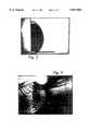
- FIG. 5is a graphic depiction of a processed profile of a sphere.
- FIG. 6is a graphic depiction of a processed profile of an optical sphere.
- FIG. 7is a three camera embodiment of the invention.
- FIG. 8is an embodiment of a processor subsystem.
- FIG. 9is a two camera embodiment of the invention.
- Front view camera 304has its optical axis generally aligned with the optical axis of the eye under exam 306 or 307.
- front view camera 304may be used for examining either left eye 307 or right eye 306, but not both.
- Side-view cameras 302 and 303are each positioned substantially orthogonal to front view camera 304.
- Left-side-view camera 303is used only for examining left eye 307 because human facial anatomy (usually a nose) substantially restricts visibility of right eye 306 from the vantage point of left-side-view camera 303.
- right-side-view camera 302is only used for examining right eye 306.
- left-side-view camera 303 and right-side-view camera 302share a common optical axis.
- a person under exam 301will face placido 305 and generally align the optical axis of right eye 306 with the optical axis of front view camera 304.
- Light source 308will cause the pattern from placido 305 to reflect off of right eye 306.
- the reflected pattern as well as a real image of the right eye 306may be captured by front-view-camera 304 and right-view-camera 302.
- the corneal image captured by front-view-camera 304is well known in the art and therefore not discussed further.
- the image captured by the right-side-view camerais not well known and provides two very useful data sources: (1) a true profile of the cornea; and (2) a view of the reflected placido rings on the temporal hemisphere.
- An example of this datais shown in FIG. 5 and FIG. 6.
- a processed interpretation of a side-view imageis shown in FIG. 6 (for a human eye) and FIG. 5 (for a sphere).
- Another typical use of the inventionis, for example, examining the left eye 307.
- a person under exam 301will face placido 305 and generally align the optical axis of left eye 307 with the optical axis of front view camera 304.
- the reflected pattern, real image and true profile of left eye 307may then be captured by front-view-camera 304 and left-view-camera 303.
- the effect of a multi-camera systemis to simultaneously achieve two views of a single eye (or cornea): a side view and a front view. It is contemplated that this effect can be achieved with fewer than three cameras. For example, two cameras may be oriented for use with one eye and then re-oriented for use with the other eye. Alternatively, one camera may be adapted with lenses or mirrors so that side and front views may be simultaneously received. Lastly, simultaneous views may be simulated by time sharing one camera with two or more views.
- the inventionalso contemplates using a third view taken from the top or bottom vantage point. This third view may lead to even further accuracy in corneal topographic mapping by providing new information as well as verification information.
- FIG. 4an abstract view of a multi-camera system is shown.
- the optical axis 406 of front-view camera 403is at angle ⁇ with the optical axis 405 of side-view camera 404.
- Any orientation of side-view camera 404 relative to front-view camera 403may be used as long as the respective optical axes are substantially orthogonal to one and other; a maximum variation of ⁇ from 75 degrees to 105 degrees is preferred. However, it has been found that better performance may be achieved for ⁇ between 85 degrees and 95 degree. Furthermore, it has also been determined that ⁇ is optimum at 90 degrees.
- angle ⁇is restricted as stated above, the relative orientation of side-camera 404 and front-camera 403 may be otherwise altered to maximize the view of the cornea.
- some patientshave facial structures that do not easily accommodate a side view of the cornea.
- the corneal viewmay be improved by rotating side-view camera 404 about the optical axis of front-view camera 406.
- processor subsystem 407is used to perform control and interface functions.
- Processor subsystem 407initiates or performs all control functions and digital operations.
- processor subsystem 407is programmed to perform the functions necessary to receive meaningful data from the multi-camera system. For example, radius of curvature, position of the limbus, auto-calibration and error correction all benefit from computational activity in processor subsystem 407.
- the functions of processor subsystem 407may be distributed across various devices or computers.
- processor subsystem 407may include processing circuitry 801, memory circuitry 803 and port 804.
- Processing circuitry 801 and memory circuitry 803are used for receiving, executing and implementing computer instructions.
- the processing circuitry 801typically comprises a PC microprocessor system, although any combination of single or multiple microprocessors or instruction fetch and execution circuitry will suffice.
- the memory circuitry 803is contemplated as a conventional PC combination of DRAM and SRAM circuits. Of course the invention may be implemented using any electronic, magnetic or other memory option.
- Port 804is the gateway between processor subsystem 407 and the outside world.
- the processor subsystem 407may also include interface elements such as monitor 802, keyboard 806, mouse 807 and printer 805. Any conventional computer may be adapted for use as processor subsystem 407.
- the inventioncontemplates the use of digital signal processing. Therefore, it is appropriate to represent the video images digitally.
- the systemmay employ a camera subsystem contained in an overall camera assembly. Referring to FIG. 7, a camera assembly having three camera subsystems is shown.
- a camera subsystem 702receives an image and then represents that image in digital form. The digitized image is then passed on to processor subsystem 407 via data line 707.
- a camera subsystem 702may contain the following: (1) a camera 701 or other device suited to receive images; and 2) a digitizer 705 or other means for creating a digital representation of the received images, e.g. a CCD or analog-to-frame-grabber arrangement.
- a camera subsystem 702may also contain a multiplexer.
- the multiplexerfunctions to select one of two side view cameras 701 in a three camera embodiment of the multi-camera system.
- the multiplexeris controlled by a processor subsystem 407 via control line 708. It is noteworthy that any part or all of a camera subsystem 702 may also be part of a processor subsystem 407.
- a patternmay be reflected off the eye by using a placido or any other reasonable means such as L.E.D.s or fiber optics.
- the inventionis not strictly limited to the examination of a human eye.
- the inventionmay also be used to obtain topography information about any eye or similarly shaped object such as a ball bearing, calibration sphere, contact lens or artificial tears.
- imagesmay be captured by means other than cameras. For example any CCD array or analog camera type device may be used.
- apex of the eyeis aligned with the optical axis of the camera through various conventional techniques. Generally, none of these techniques can provide a precise alignment because, when only a front-view camera is employed, the system must estimate the Z-axis location of the apex.
- the current inventionaddresses this problem by precisely locating the apex via a side-view camera.
- a side-view camera according to the inventioncan capture an image of the true corneal profile, e.g. FIG. 1 shows a drawing of a corneal profile and FIG. 6 shows an actual photo of the same.
- the apexis identified as the leading edge of the profile. For example, apex 101 is found at the leading edge in the corneal profile of FIG. 1.
- side-view camera 404captures an image of the corneal profile.
- the imageis digitized by a digitizer in the camera 404's subsystem.
- the apex, or leading edge,is then located according to the procedures in the supplemental disclosure to this specification.
- processor subsystem 407receives digitized images of both front and side views. Using the front view, processor subsystem 407 may determine the expected location of the apex in three dimensions (X, Y and Z) and the actual location in 2 dimensions (X and Y). As indicated above, using the side view, processor subsystem 407 may determine the actual Z-axis location of the apex.
- processor subsystem 407may generate an error signal indicating or representing the locational difference between the true and expected locations of the apex. Given the foregoing information, processor subsystem 407 may also generate a signal indicating or representing the position of the apex relative to an X, Y, Z coordinate system such as the system defined by point 408 and the intersection of side-view optical axis 405 with front-view optical axis 406. Of course, all the described activity may be visually represented on monitor 802 or by printing of printer 805.
- the inventioncontemplates using the described error signal to physically change the position of the camera assembly so that the apex of the eye (or other unit under test) is aligned with the optical axis of the front-view camera. This position may be changed either manually or automatically.
- front-view camera 905is connected to side-view camera 906 by rigid connection 901.
- mechanical controller 902has a moving arm that is firmly coupled to rigid connection 901. This overall assembly allows mechanical controller 902 to move the camera assembly without changing the relative positioning between front-view camera 905 and side view camera 906.
- front-view and side-view imagesare captured and digitized.
- the digitized imagesare processed in processor subsystem 407 and an error signal is generated representing the actual position of apex 904 relative to the desired position for the apex.
- the desired positionis typically at origin 905 which is the intersection of the optical axis. However, the desired position may be elsewhere, e.g. the system may simply seek to align a single optical axis with the apex.
- the error signalis used, either directly or indirectly, to control the actuation of mechanical controller 901.
- mechanical controller 901Upon receiving an actuation signal, mechanical controller 901 will alter the position of the camera assembly. For higher accuracy this process may be iterated until the apex is positioned precisely as desired.
- the error signalmay be used in other ways.
- the error signalmay be used for the following purposes: 1) to correct calculations (such as radius of curvature) made on an eye (or other unit under test) that is not ideally positioned relative to the cameras; or 2) to generate a graphical representation of the error to display on a monitor or printer.
- a side-view imageallows calculation of radius of curvature, along the horizontal, up to the limbus. The calculation is facilitated by the side-view camera's capture of the reflected placido pattern (typically rings). Furthermore, curvature is ultimately determined by collecting data from an eye (or other unit under test) and interpolating the collected data with similar data taken from objects having known radii of curvature.
- the processbegins by collecting a reference set of reflecting surfaces (calibration balls) having known radii of curvature.
- the reference setshould include enough balls of varying size to create a scale large enough and granular enough so that accurate interpolation is possible against data taken from the intended class of units under test.
- Each ballmay be placed under test, for example by (i) reflecting rings off the ball, (ii) capturing an image of the ball with a side view camera, and (iii) measuring the distance from the apex to the edges of all the rings (or measuring the distance between adjoining ring edges). The measured distances may be cataloged with the corresponding radius of curvature of the examined ball.
- the multi-camera systemmay also be used to find the location of the limbus in three space (X,Y,Z).
- the Z-axis position of the limbusis obtained with the side-view camera. Once a side view image is obtained, a point on the limbus edge can be found by locating the transition from homogeneous white region to non-homogeneous region on any horizontal line in the side view corneal image. All the relevant points along the limbus may be located in this same manner.
- a real image from the front cameramay then be used to locate the limbus' Y-axis and X-axis position. Once again, the limbus is located by finding the transition from homogeneous white region to non-homogeneous region. Through this process, the limbus if finally located in three space.
- locating the limbusmay be conveniently accomplished by digitizing the captured images. Since the limbus will always embody a transition from homogeneous white region to non-homogeneous region, the limbus is easily located through various image processing techniques. For example, an intensity profile of the image will show white regions as low energy regions and reflected ring regions as high energy regions. Therefore the location of the limbus will correspond to the transition from a high energy to a low energy region.
- a corneal profilemay be located by using the multi-camera system. Specifically, a profile along the horizontal meridian is found by using a virtual image (the reflected pattern) obtained through the side-view camera. The virtual image is digitized (to create an intensity profile) and then high pass filtered. The profile is then located at the near-camera boundary between a high energy region and a low energy region. This process is described in detail in appendix 1.
Landscapes
- Life Sciences & Earth Sciences (AREA)
- Health & Medical Sciences (AREA)
- Physics & Mathematics (AREA)
- Heart & Thoracic Surgery (AREA)
- Molecular Biology (AREA)
- Ophthalmology & Optometry (AREA)
- Engineering & Computer Science (AREA)
- Biomedical Technology (AREA)
- General Physics & Mathematics (AREA)
- Medical Informatics (AREA)
- Biophysics (AREA)
- Surgery (AREA)
- Animal Behavior & Ethology (AREA)
- General Health & Medical Sciences (AREA)
- Public Health (AREA)
- Veterinary Medicine (AREA)
- Eye Examination Apparatus (AREA)
- Image Processing (AREA)
Abstract
Description
Claims (32)
Priority Applications (2)
| Application Number | Priority Date | Filing Date | Title |
|---|---|---|---|
| US08/638,875US5847804A (en) | 1994-10-28 | 1996-04-25 | Multi-camera corneal analysis system |
| US08/956,515US5953100A (en) | 1994-10-28 | 1997-10-23 | Multi-camera corneal analysis system |
Applications Claiming Priority (2)
| Application Number | Priority Date | Filing Date | Title |
|---|---|---|---|
| US33097994A | 1994-10-28 | 1994-10-28 | |
| US08/638,875US5847804A (en) | 1994-10-28 | 1996-04-25 | Multi-camera corneal analysis system |
Related Parent Applications (1)
| Application Number | Title | Priority Date | Filing Date |
|---|---|---|---|
| US33097994AContinuation | 1994-10-28 | 1994-10-28 |
Related Child Applications (1)
| Application Number | Title | Priority Date | Filing Date |
|---|---|---|---|
| US08/956,515ContinuationUS5953100A (en) | 1994-10-28 | 1997-10-23 | Multi-camera corneal analysis system |
Publications (1)
| Publication Number | Publication Date |
|---|---|
| US5847804Atrue US5847804A (en) | 1998-12-08 |
Family
ID=23292124
Family Applications (2)
| Application Number | Title | Priority Date | Filing Date |
|---|---|---|---|
| US08/638,875Expired - Fee RelatedUS5847804A (en) | 1994-10-28 | 1996-04-25 | Multi-camera corneal analysis system |
| US08/956,515Expired - Fee RelatedUS5953100A (en) | 1994-10-28 | 1997-10-23 | Multi-camera corneal analysis system |
Family Applications After (1)
| Application Number | Title | Priority Date | Filing Date |
|---|---|---|---|
| US08/956,515Expired - Fee RelatedUS5953100A (en) | 1994-10-28 | 1997-10-23 | Multi-camera corneal analysis system |
Country Status (6)
| Country | Link |
|---|---|
| US (2) | US5847804A (en) |
| EP (1) | EP0843529B1 (en) |
| JP (1) | JPH10507953A (en) |
| AU (1) | AU4197496A (en) |
| DE (1) | DE69526977T2 (en) |
| WO (1) | WO1996013199A2 (en) |
Cited By (62)
| Publication number | Priority date | Publication date | Assignee | Title |
|---|---|---|---|---|
| US6095651A (en)* | 1996-12-23 | 2000-08-01 | University Of Rochester | Method and apparatus for improving vision and the resolution of retinal images |
| US6199986B1 (en) | 1999-10-21 | 2001-03-13 | University Of Rochester | Rapid, automatic measurement of the eye's wave aberration |
| US6270221B1 (en) | 1998-08-19 | 2001-08-07 | Alcon Universal Ltd. | Apparatus and method for measuring vision defects of a human eye |
| US6271915B1 (en) | 1996-11-25 | 2001-08-07 | Autonomous Technologies Corporation | Objective measurement and correction of optical systems using wavefront analysis |
| WO2001066004A1 (en) | 2000-03-09 | 2001-09-13 | Lasersight Technologies, Inc. | Combination advanced corneal topography/wave front aberration measurement |
| WO2001070099A3 (en)* | 2000-03-23 | 2002-06-27 | Bausch & Lomb | Acquisition of multiple eye topography exams |
| US6497483B2 (en) | 2000-05-08 | 2002-12-24 | Alcon, Inc. | Apparatus and method for objective measurement of optical systems using wavefront analysis |
| US6575573B2 (en) | 2001-10-17 | 2003-06-10 | Carl Zeiss Ophthalmic Systems, Inc. | Method and apparatus for measuring a corneal profile of an eye |
| US6578963B2 (en) | 2000-04-19 | 2003-06-17 | Alcon Universal Ltd. | Wavefront sensor for objective measurement of an optical system and associated methods |
| US6626896B2 (en) | 1994-04-25 | 2003-09-30 | Alcon, Inc. | Method of correcting vision |
| US20050007551A1 (en)* | 1998-10-07 | 2005-01-13 | Tracey Technologies, Llc | Method and device for determining refractive components and visual function of the eye for vision correction |
| US20050057723A1 (en)* | 2001-04-16 | 2005-03-17 | Youssef Wakil | Determining clinical refraction of eye |
| US6932475B2 (en) | 1998-10-07 | 2005-08-23 | Tracey Technologies, L.L.C. | Device for measuring aberration refraction of the eye |
| US7380942B2 (en) | 2002-10-04 | 2008-06-03 | Sergiy Molebny | Method for measuring the wave aberrations of the eye |
| US20100123873A1 (en)* | 2008-11-14 | 2010-05-20 | Amo Wavefront Sciences, Llc | Method of qualifying light spots for optical measurements and measurement instrument employing method of qualifying light spots |
| US20100211054A1 (en)* | 2007-04-25 | 2010-08-19 | Wavelight Ag | Device, Method, and Control Program for Refractive Surgery |
| US7796791B2 (en) | 2002-11-07 | 2010-09-14 | Conformis, Inc. | Methods for determining meniscal size and shape and for devising treatment |
| US7799077B2 (en) | 2002-10-07 | 2010-09-21 | Conformis, Inc. | Minimally invasive joint implant with 3-dimensional geometry matching the articular surfaces |
| US7881768B2 (en) | 1998-09-14 | 2011-02-01 | The Board Of Trustees Of The Leland Stanford Junior University | Assessing the condition of a joint and devising treatment |
| EP2292189A2 (en) | 2002-11-27 | 2011-03-09 | Conformis, Inc. | Patient selectable surgical tools |
| US7976163B2 (en) | 2007-06-27 | 2011-07-12 | Amo Wavefront Sciences Llc | System and method for measuring corneal topography |
| US7981158B2 (en) | 2001-05-25 | 2011-07-19 | Conformis, Inc. | Patient selectable joint arthroplasty devices and surgical tools |
| US7988290B2 (en) | 2007-06-27 | 2011-08-02 | AMO Wavefront Sciences LLC. | Systems and methods for measuring the shape and location of an object |
| USRE42782E1 (en) | 1998-10-07 | 2011-10-04 | Tracey Technologies, Llc | Method and device for synchronous mapping of the total refraction non-homogeneity of the eye and its refractive components |
| US8036729B2 (en) | 1998-09-14 | 2011-10-11 | The Board Of Trustees Of The Leland Stanford Junior University | Assessing the condition of a joint and devising treatment |
| US8066708B2 (en) | 2001-05-25 | 2011-11-29 | Conformis, Inc. | Patient selectable joint arthroplasty devices and surgical tools |
| US8122582B2 (en) | 2001-05-25 | 2012-02-28 | Conformis, Inc. | Surgical tools facilitating increased accuracy, speed and simplicity in performing joint arthroplasty |
| US8234097B2 (en) | 2001-05-25 | 2012-07-31 | Conformis, Inc. | Automated systems for manufacturing patient-specific orthopedic implants and instrumentation |
| US8265730B2 (en) | 1998-09-14 | 2012-09-11 | The Board Of Trustees Of The Leland Stanford Junior University | Assessing the condition of a joint and preventing damage |
| US8337507B2 (en) | 2001-05-25 | 2012-12-25 | Conformis, Inc. | Methods and compositions for articular repair |
| US8439926B2 (en) | 2001-05-25 | 2013-05-14 | Conformis, Inc. | Patient selectable joint arthroplasty devices and surgical tools |
| US8480754B2 (en) | 2001-05-25 | 2013-07-09 | Conformis, Inc. | Patient-adapted and improved articular implants, designs and related guide tools |
| US8500740B2 (en) | 2006-02-06 | 2013-08-06 | Conformis, Inc. | Patient-specific joint arthroplasty devices for ligament repair |
| US8545569B2 (en) | 2001-05-25 | 2013-10-01 | Conformis, Inc. | Patient selectable knee arthroplasty devices |
| US8556983B2 (en) | 2001-05-25 | 2013-10-15 | Conformis, Inc. | Patient-adapted and improved orthopedic implants, designs and related tools |
| WO2013155501A1 (en) | 2012-04-13 | 2013-10-17 | Conformis, Inc. | Patient adapted joint arthroplasty devices, surgical tools and methods of use |
| US8585687B2 (en) | 2007-05-11 | 2013-11-19 | Amo Development, Llc | Combined wavefront and topography systems and methods |
| US8617242B2 (en) | 2001-05-25 | 2013-12-31 | Conformis, Inc. | Implant device and method for manufacture |
| US8622546B2 (en) | 2011-06-08 | 2014-01-07 | Amo Wavefront Sciences, Llc | Method of locating valid light spots for optical measurement and optical measurement instrument employing method of locating valid light spots |
| US8623026B2 (en) | 2006-02-06 | 2014-01-07 | Conformis, Inc. | Patient selectable joint arthroplasty devices and surgical tools incorporating anatomical relief |
| US8682052B2 (en) | 2008-03-05 | 2014-03-25 | Conformis, Inc. | Implants for altering wear patterns of articular surfaces |
| US8735773B2 (en) | 2007-02-14 | 2014-05-27 | Conformis, Inc. | Implant device and method for manufacture |
| US8771365B2 (en) | 2009-02-25 | 2014-07-08 | Conformis, Inc. | Patient-adapted and improved orthopedic implants, designs, and related tools |
| US8808303B2 (en) | 2009-02-24 | 2014-08-19 | Microport Orthopedics Holdings Inc. | Orthopedic surgical guide |
| US8882847B2 (en) | 2001-05-25 | 2014-11-11 | Conformis, Inc. | Patient selectable knee joint arthroplasty devices |
| US8951260B2 (en) | 2001-05-25 | 2015-02-10 | Conformis, Inc. | Surgical cutting guide |
| US9020788B2 (en) | 1997-01-08 | 2015-04-28 | Conformis, Inc. | Patient-adapted and improved articular implants, designs and related guide tools |
| US9017334B2 (en) | 2009-02-24 | 2015-04-28 | Microport Orthopedics Holdings Inc. | Patient specific surgical guide locator and mount |
| US20160066785A1 (en)* | 2014-09-09 | 2016-03-10 | Lawrence J. Gerrans | System And Method for Visualization of Ocular Anatomy |
| US9286686B2 (en) | 1998-09-14 | 2016-03-15 | The Board Of Trustees Of The Leland Stanford Junior University | Assessing the condition of a joint and assessing cartilage loss |
| US9308091B2 (en) | 2001-05-25 | 2016-04-12 | Conformis, Inc. | Devices and methods for treatment of facet and other joints |
| US9486226B2 (en) | 2012-04-18 | 2016-11-08 | Conformis, Inc. | Tibial guides, tools, and techniques for resecting the tibial plateau |
| US9603711B2 (en) | 2001-05-25 | 2017-03-28 | Conformis, Inc. | Patient-adapted and improved articular implants, designs and related guide tools |
| US9649117B2 (en) | 2009-02-24 | 2017-05-16 | Microport Orthopedics Holdings, Inc. | Orthopedic surgical guide |
| US9675471B2 (en) | 2012-06-11 | 2017-06-13 | Conformis, Inc. | Devices, techniques and methods for assessing joint spacing, balancing soft tissues and obtaining desired kinematics for joint implant components |
| US10039445B1 (en)* | 2004-04-01 | 2018-08-07 | Google Llc | Biosensors, communicators, and controllers monitoring eye movement and methods for using them |
| US10085839B2 (en) | 2004-01-05 | 2018-10-02 | Conformis, Inc. | Patient-specific and patient-engineered orthopedic implants |
| WO2022167932A1 (en)* | 2021-02-08 | 2022-08-11 | Alcon Inc. | Multi-view corneal topographer |
| US12108959B2 (en) | 2019-05-29 | 2024-10-08 | Wright Medical Technology, Inc. | Preparing a tibia for receiving tibial implant component of a replacement ankle |
| US12383287B2 (en) | 2009-02-24 | 2025-08-12 | Microport Orthopedics Holdings, Inc. | Systems and methods for installing an orthopedic implant |
| US12396739B2 (en) | 2020-01-17 | 2025-08-26 | Wright Medical Technology, Inc. | Guidance tools, systems, and methods |
| US12440227B2 (en) | 2022-01-05 | 2025-10-14 | Wright Medical Technology, Inc. | Preparing a tibia for receiving tibial implant component of a replacement ankle |
Families Citing this family (10)
| Publication number | Priority date | Publication date | Assignee | Title |
|---|---|---|---|---|
| US6116738A (en)* | 1997-01-06 | 2000-09-12 | Vismed, Inc. | Corneal topographer with central and peripheral measurement capability |
| US6129722A (en) | 1999-03-10 | 2000-10-10 | Ruiz; Luis Antonio | Interactive corrective eye surgery system with topography and laser system interface |
| RU2147828C1 (en)* | 1999-05-31 | 2000-04-27 | ООО Медицинский научно-исследовательский офтальмологический центр "Новый взгляд" | Method for determining corneal flap border in repeated special laser keratomyleusis operation |
| US6193371B1 (en)* | 2000-03-27 | 2001-02-27 | Richard Snook | Keratometer/pachymeter |
| US6663242B1 (en) | 2001-03-12 | 2003-12-16 | Wayne Davenport | Simultaneous, wavelength multiplexed vision screener |
| US6616277B1 (en) | 2001-07-02 | 2003-09-09 | Vision Research Corporation | Sequential eye screening method and apparatus |
| EP2314200B1 (en) | 2009-10-21 | 2016-01-13 | SIS AG, Surgical Instrument Systems | Method and device for measuring a cornea |
| DE102011102354A1 (en) | 2011-05-24 | 2012-11-29 | Carl Zeiss Meditec Ag | System for determining surface shape of cornea of eye, has keratoscope, illuminating unit, image recording unit with telecentric image capturing and control- and evaluation unit |
| DE102011102355A1 (en) | 2011-05-24 | 2012-11-29 | Carl Zeiss Meditec Ag | System for determining the topography of the cornea of an eye |
| KR102210054B1 (en)* | 2013-04-08 | 2021-02-02 | 스냅 아이엔씨 | Distance estimation using multi-camera device |
Citations (15)
| Publication number | Priority date | Publication date | Assignee | Title |
|---|---|---|---|---|
| US3169459A (en)* | 1963-03-11 | 1965-02-16 | Michael A Friedberg | Method of determining surface contours of an eye |
| US4420228A (en)* | 1980-06-12 | 1983-12-13 | Humphrey Instruments, Inc. | Method and apparatus for analysis of corneal shape |
| US4597648A (en)* | 1983-04-01 | 1986-07-01 | Keratometer Research And Development | Keratometer |
| US4662730A (en)* | 1984-10-18 | 1987-05-05 | Kerascan, Inc. | Scanning keratometers |
| US4685140A (en)* | 1984-06-26 | 1987-08-04 | Kera Corporation | Keratograph autoscanner system |
| US4710003A (en)* | 1982-10-21 | 1987-12-01 | Canon Kabushiki Kaisha | Cornea shape measuring apparatus |
| US4859051A (en)* | 1986-12-25 | 1989-08-22 | Tokyo Kogaku Kikai Kabushiki Kaisha | Eye testing apparatus |
| US4863260A (en)* | 1987-11-04 | 1989-09-05 | Computed Anatomy Inc. | System for topographical modeling of anatomical surfaces |
| US4978213A (en)* | 1987-08-26 | 1990-12-18 | El Hage Sami G | Apparatus for determining the contour of the cornea of a human eye |
| US4998819A (en)* | 1987-11-25 | 1991-03-12 | Taunton Technologies, Inc. | Topography measuring apparatus |
| US5110200A (en)* | 1989-06-30 | 1992-05-05 | Technitex, Inc. | Video keratometer |
| US5212506A (en)* | 1990-11-27 | 1993-05-18 | Atr Auditory And Visual Perception Research Laboratories | Analysis method of eyeball control system |
| EP0589857A1 (en)* | 1992-09-23 | 1994-03-30 | Optikon Oftalmologia S.P.A. | An apparatus for topographical analysis of anatomical surfaces, in particular of cornea |
| US5345281A (en)* | 1992-12-17 | 1994-09-06 | John Taboada | Eye tracking system and method |
| US5382989A (en)* | 1992-09-17 | 1995-01-17 | Atr Auditory And Visual Perception Research Laboratories | Apparatus for examining gaze shift in depth direction |
Family Cites Families (4)
| Publication number | Priority date | Publication date | Assignee | Title |
|---|---|---|---|---|
| JPS5542624A (en)* | 1978-09-20 | 1980-03-26 | Canon Kk | Automatic eye refraction measuring system |
| JPS565637A (en)* | 1979-06-28 | 1981-01-21 | Tokyo Optical | Operation distance detector in ophthalmology machine |
| US5016282A (en)* | 1988-07-14 | 1991-05-14 | Atr Communication Systems Research Laboratories | Eye tracking image pickup apparatus for separating noise from feature portions |
| US5777718A (en)* | 1992-12-31 | 1998-07-07 | Canon Kabushiki Kaisha | Eye refractometer |
- 1995
- 1995-10-30DEDE69526977Tpatent/DE69526977T2/ennot_activeExpired - Fee Related
- 1995-10-30WOPCT/US1995/013993patent/WO1996013199A2/enactiveIP Right Grant
- 1995-10-30EPEP95940570Apatent/EP0843529B1/ennot_activeExpired - Lifetime
- 1995-10-30JPJP8514798Apatent/JPH10507953A/ennot_activeCeased
- 1995-10-30AUAU41974/96Apatent/AU4197496A/ennot_activeAbandoned
- 1996
- 1996-04-25USUS08/638,875patent/US5847804A/ennot_activeExpired - Fee Related
- 1997
- 1997-10-23USUS08/956,515patent/US5953100A/ennot_activeExpired - Fee Related
Patent Citations (16)
| Publication number | Priority date | Publication date | Assignee | Title |
|---|---|---|---|---|
| US3169459A (en)* | 1963-03-11 | 1965-02-16 | Michael A Friedberg | Method of determining surface contours of an eye |
| US4420228A (en)* | 1980-06-12 | 1983-12-13 | Humphrey Instruments, Inc. | Method and apparatus for analysis of corneal shape |
| US4710003A (en)* | 1982-10-21 | 1987-12-01 | Canon Kabushiki Kaisha | Cornea shape measuring apparatus |
| US4597648A (en)* | 1983-04-01 | 1986-07-01 | Keratometer Research And Development | Keratometer |
| US4685140A (en)* | 1984-06-26 | 1987-08-04 | Kera Corporation | Keratograph autoscanner system |
| US4662730A (en)* | 1984-10-18 | 1987-05-05 | Kerascan, Inc. | Scanning keratometers |
| US4859051A (en)* | 1986-12-25 | 1989-08-22 | Tokyo Kogaku Kikai Kabushiki Kaisha | Eye testing apparatus |
| US4978213A (en)* | 1987-08-26 | 1990-12-18 | El Hage Sami G | Apparatus for determining the contour of the cornea of a human eye |
| US4978213B1 (en)* | 1987-08-26 | 1997-03-11 | Alcon Lab Inc | Apparatus for determining the contour of the cornea of a human eye |
| US4863260A (en)* | 1987-11-04 | 1989-09-05 | Computed Anatomy Inc. | System for topographical modeling of anatomical surfaces |
| US4998819A (en)* | 1987-11-25 | 1991-03-12 | Taunton Technologies, Inc. | Topography measuring apparatus |
| US5110200A (en)* | 1989-06-30 | 1992-05-05 | Technitex, Inc. | Video keratometer |
| US5212506A (en)* | 1990-11-27 | 1993-05-18 | Atr Auditory And Visual Perception Research Laboratories | Analysis method of eyeball control system |
| US5382989A (en)* | 1992-09-17 | 1995-01-17 | Atr Auditory And Visual Perception Research Laboratories | Apparatus for examining gaze shift in depth direction |
| EP0589857A1 (en)* | 1992-09-23 | 1994-03-30 | Optikon Oftalmologia S.P.A. | An apparatus for topographical analysis of anatomical surfaces, in particular of cornea |
| US5345281A (en)* | 1992-12-17 | 1994-09-06 | John Taboada | Eye tracking system and method |
Non-Patent Citations (36)
| Title |
|---|
| "Holographic Process Offers Best Potential for Real-time Modeling/Corneal Imaging", Oscular Surgery News, 6(4):16 & 18 (Feb. 15, 1988). |
| "Real-Time Keratometer" Nasa Tech. Briefs, NASA's Jet Propulsion Laboratory, Pasadena, California, pp. 55-56 (Mar. 1988). |
| "Three-Dimensional Ultrasonic Imaging of the Cornea, A Proposed Technique Would Generate Pictures of Curved Surfaces", NASA Tech Briefs, NASA's Jet Propulsion Laboratory, Pasadena, California, p. 99 (Sep. 1988). |
| Bibby, et al., "Corneal Topography-Its Measurement Description Application", Reprinted from Contact Lens Forum (Nov./Dec. 1976-Jan. 1977). |
| Bibby, et al., Corneal Topography Its Measurement Description Application , Reprinted from Contact Lens Forum (Nov./Dec. 1976 Jan. 1977).* |
| Bogan, et al., "Classification of Normal Corneal Topography Based On Computer-Assisted Videokeratopgraphy", Archive of Ophthalmology, 108:945-949 (Jul. 1990). |
| Bogan, et al., Classification of Normal Corneal Topography Based On Computer Assisted Videokeratopgraphy , Archive of Ophthalmology, 108:945 949 (Jul. 1990).* |
| Brochure: "The Leading Edge In Eye Care", Computer Graphics World, (Mar. 1987). |
| Brochure: The Leading Edge In Eye Care , Computer Graphics World, (Mar. 1987).* |
| Cotran, et al., "An Adaptation of the Topcon Slit Lamp for Photokeratoscopy", CLAO Journal, 13(5):277-279 (Sep. 1987). |
| Cotran, et al., An Adaptation of the Topcon Slit Lamp for Photokeratoscopy , CLAO Journal, 13(5):277 279 (Sep. 1987).* |
| Doss et al., "Method for Calculation of Corneal Profile and Power Distribution", submitted to the Archives of Ophthalmology, pp. 1-14 & four pgs. drawings. (Dec. 1978). |
| Doss et al., Method for Calculation of Corneal Profile and Power Distribution , submitted to the Archives of Ophthalmology, pp. 1 14 & four pgs. drawings. (Dec. 1978).* |
| Gormley, et al., "Corneal Modeling", Cornea, 7(1):30-35 (1988). |
| Gormley, et al., Corneal Modeling , Cornea, 7(1):30 35 (1988).* |
| Henslee, et al., "New corneal Shapes In Keratorefractive Surgery", Ophthalmology, 90(3):245-250 (Mar. 1983). |
| Henslee, et al., New corneal Shapes In Keratorefractive Surgery , Ophthalmology , 90(3):245 250 (Mar. 1983).* |
| Holographic Process Offers Best Potential for Real time Modeling/Corneal Imaging , Oscular Surgery News, 6(4):16 & 18 (Feb. 15, 1988).* |
| Klyce, Stephen D., "Computer-Assisted Corneal Topography", Investigative Opthalmology & Visual Science, 13(12):1426-1435 (Dec. 1984). |
| Klyce, Stephen D., Computer Assisted Corneal Topography , Investigative Opthalmology & Visual Science, 13(12):1426 1435 (Dec. 1984).* |
| Klyce, Stephen, "Corneal Topography Graphically Rendered By New System," Ocular Surgery News, pp. 28-29 (Apr. 1, 1987). |
| Klyce, Stephen, Corneal Topography Graphically Rendered By New System, Ocular Surgery News, pp. 28 29 (Apr. 1, 1987).* |
| Koch, et al., "The Corneal EyeSys System: Accuracy Analysis and Reproducibility of First-Generation Prototype", Refractive & Corneal Surgery, 5:424-429 (Nov./Dec. 1989). |
| Koch, et al., The Corneal EyeSys System: Accuracy Analysis and Reproducibility of First Generation Prototype , Refractive & Corneal Surgery, 5:424 429 (Nov./Dec. 1989).* |
| Maguire, et al., "Graphic Presentation of Computer-Analyzed Keratoscope Photographs", Arch. Ophthalmol., vol. 105, pp. 223-230 (Feb. 1987). |
| Maguire, et al., Graphic Presentation of Computer Analyzed Keratoscope Photographs , Arch. Ophthalmol., vol. 105, pp. 223 230 (Feb. 1987).* |
| Real Time Keratometer Nasa Tech. Briefs, NASA s Jet Propulsion Laboratory, Pasadena, California, pp. 55 56 (Mar. 1988).* |
| Rowsey, et al., "Corneal Topography, Corneascope", Archive of Ophthalmology, 99:1093-1100 (Jun. 1981). |
| Rowsey, et al., "Prospective Evaluation of Radial Keratotomy, Photokeratorscope Corneal Topography", Ophthalmology, 95(3):322-334 (Mar. 1988). |
| Rowsey, et al., Corneal Topography, Corneascope , Archive of Ophthalmology, 99:1093 1100 (Jun. 1981).* |
| Rowsey, et al., Prospective Evaluation of Radial Keratotomy, Photokeratorscope Corneal Topography , Ophthalmology, 95(3):322 334 (Mar. 1988).* |
| The University of Houston University Park Subgrant Under The Coordinating Board, Texas University & College System, subgrantor Technitex, Inc., Development of the Photo Keratographs (Aug. 1, 1986 Jan. 31, 1987).* |
| The University of Houston-University Park Subgrant Under The Coordinating Board, Texas University & College System, subgrantor-Technitex, Inc., Development of the Photo-Keratographs-(Aug. 1, 1986-Jan. 31, 1987). |
| Three Dimensional Ultrasonic Imaging of the Cornea, A Proposed Technique Would Generate Pictures of Curved Surfaces , NASA Tech Briefs, NASA s Jet Propulsion Laboratory, Pasadena, California, p. 99 (Sep. 1988).* |
| Villasenor, et al., "Corneal Topography and Refractive Surgery", Cornea, 2:323-331 (1983). |
| Villasenor, et al., Corneal Topography and Refractive Surgery , Cornea, 2:323 331 (1983).* |
Cited By (187)
| Publication number | Priority date | Publication date | Assignee | Title |
|---|---|---|---|---|
| US6626896B2 (en) | 1994-04-25 | 2003-09-30 | Alcon, Inc. | Method of correcting vision |
| US6626895B2 (en) | 1994-04-25 | 2003-09-30 | Alcon, Inc. | Laser beam delivery system |
| US6626894B2 (en) | 1994-04-25 | 2003-09-30 | Alcon, Inc. | Method of ablating a moving eye |
| US6626898B2 (en) | 1994-04-25 | 2003-09-30 | Alcon, Inc. | Flying spot laser ablation method |
| US6626897B2 (en) | 1994-04-25 | 2003-09-30 | Alcon, Inc. | Method of redirecting an ablating laser beam |
| US6271915B1 (en) | 1996-11-25 | 2001-08-07 | Autonomous Technologies Corporation | Objective measurement and correction of optical systems using wavefront analysis |
| US6271914B1 (en) | 1996-11-25 | 2001-08-07 | Autonomous Technologies Corporation | Objective measurement and correction of optical systems using wavefront analysis |
| US6095651A (en)* | 1996-12-23 | 2000-08-01 | University Of Rochester | Method and apparatus for improving vision and the resolution of retinal images |
| US6948818B2 (en) | 1996-12-23 | 2005-09-27 | University Of Rochester | Method and apparatus for improving vision and the resolution of retinal images |
| US20060044510A1 (en)* | 1996-12-23 | 2006-03-02 | University Of Rochester | Method and apparatus for improving vision and the resolution of retinal images |
| US6379005B1 (en) | 1996-12-23 | 2002-04-30 | University Of Rochester | Method and apparatus for improving vision and the resolution of retinal images |
| US7416305B2 (en) | 1996-12-23 | 2008-08-26 | University Of Rochester | Method and apparatus for improving vision and the resolution of retinal images |
| US9020788B2 (en) | 1997-01-08 | 2015-04-28 | Conformis, Inc. | Patient-adapted and improved articular implants, designs and related guide tools |
| US6270221B1 (en) | 1998-08-19 | 2001-08-07 | Alcon Universal Ltd. | Apparatus and method for measuring vision defects of a human eye |
| US8112142B2 (en) | 1998-09-14 | 2012-02-07 | The Board Of Trustees Of The Leland Stanford Junior University | Assessing the condition of a joint and devising treatment |
| US7881768B2 (en) | 1998-09-14 | 2011-02-01 | The Board Of Trustees Of The Leland Stanford Junior University | Assessing the condition of a joint and devising treatment |
| US8036729B2 (en) | 1998-09-14 | 2011-10-11 | The Board Of Trustees Of The Leland Stanford Junior University | Assessing the condition of a joint and devising treatment |
| US9286686B2 (en) | 1998-09-14 | 2016-03-15 | The Board Of Trustees Of The Leland Stanford Junior University | Assessing the condition of a joint and assessing cartilage loss |
| US8369926B2 (en) | 1998-09-14 | 2013-02-05 | The Board Of Trustees Of The Leland Stanford Junior University | Assessing the condition of a joint and devising treatment |
| US8862202B2 (en) | 1998-09-14 | 2014-10-14 | The Board Of Trustees Of The Leland Stanford Junior University | Assessing the condition of a joint and preventing damage |
| USRE43282E1 (en) | 1998-09-14 | 2012-03-27 | The Board Of Trustees Of The Leland Stanford Junior University | Assessing the condition of a joint and devising treatment |
| US8306601B2 (en) | 1998-09-14 | 2012-11-06 | The Board Of Trustees Of The Leland Stanford Junior University | Assessing the condition of a joint and devising treatment |
| US8265730B2 (en) | 1998-09-14 | 2012-09-11 | The Board Of Trustees Of The Leland Stanford Junior University | Assessing the condition of a joint and preventing damage |
| US20050007551A1 (en)* | 1998-10-07 | 2005-01-13 | Tracey Technologies, Llc | Method and device for determining refractive components and visual function of the eye for vision correction |
| US7303281B2 (en) | 1998-10-07 | 2007-12-04 | Tracey Technologies, Llc | Method and device for determining refractive components and visual function of the eye for vision correction |
| US6932475B2 (en) | 1998-10-07 | 2005-08-23 | Tracey Technologies, L.L.C. | Device for measuring aberration refraction of the eye |
| USRE42782E1 (en) | 1998-10-07 | 2011-10-04 | Tracey Technologies, Llc | Method and device for synchronous mapping of the total refraction non-homogeneity of the eye and its refractive components |
| US6299311B1 (en) | 1999-10-21 | 2001-10-09 | University Of Rochester | Rapid, automatic measurement of the eye's wave aberration |
| US6199986B1 (en) | 1999-10-21 | 2001-03-13 | University Of Rochester | Rapid, automatic measurement of the eye's wave aberration |
| WO2001066004A1 (en) | 2000-03-09 | 2001-09-13 | Lasersight Technologies, Inc. | Combination advanced corneal topography/wave front aberration measurement |
| EP1488733A3 (en)* | 2000-03-23 | 2005-08-17 | Bausch & Lomb Incorporated | Acquisition of multiple eye topography exams |
| WO2001070099A3 (en)* | 2000-03-23 | 2002-06-27 | Bausch & Lomb | Acquisition of multiple eye topography exams |
| US6578963B2 (en) | 2000-04-19 | 2003-06-17 | Alcon Universal Ltd. | Wavefront sensor for objective measurement of an optical system and associated methods |
| US6497483B2 (en) | 2000-05-08 | 2002-12-24 | Alcon, Inc. | Apparatus and method for objective measurement of optical systems using wavefront analysis |
| US7311400B2 (en) | 2001-04-16 | 2007-12-25 | Tracey Technologies, Llc | Determining clinical refraction of eye |
| US20050057723A1 (en)* | 2001-04-16 | 2005-03-17 | Youssef Wakil | Determining clinical refraction of eye |
| US9387079B2 (en) | 2001-05-25 | 2016-07-12 | Conformis, Inc. | Patient-adapted and improved articular implants, designs and related guide tools |
| US8951259B2 (en) | 2001-05-25 | 2015-02-10 | Conformis, Inc. | Patient selectable joint arthroplasty devices and surgical tools |
| US9877790B2 (en) | 2001-05-25 | 2018-01-30 | Conformis, Inc. | Tibial implant and systems with variable slope |
| US7981158B2 (en) | 2001-05-25 | 2011-07-19 | Conformis, Inc. | Patient selectable joint arthroplasty devices and surgical tools |
| US9775680B2 (en) | 2001-05-25 | 2017-10-03 | Conformis, Inc. | Patient-adapted and improved articular implants, designs and related guide tools |
| US8062302B2 (en) | 2001-05-25 | 2011-11-22 | Conformis, Inc. | Surgical tools for arthroplasty |
| US8066708B2 (en) | 2001-05-25 | 2011-11-29 | Conformis, Inc. | Patient selectable joint arthroplasty devices and surgical tools |
| US9700971B2 (en) | 2001-05-25 | 2017-07-11 | Conformis, Inc. | Implant device and method for manufacture |
| US8083745B2 (en) | 2001-05-25 | 2011-12-27 | Conformis, Inc. | Surgical tools for arthroplasty |
| US8105330B2 (en) | 2001-05-25 | 2012-01-31 | Conformis, Inc. | Patient selectable joint arthroplasty devices and surgical tools |
| US9603711B2 (en) | 2001-05-25 | 2017-03-28 | Conformis, Inc. | Patient-adapted and improved articular implants, designs and related guide tools |
| US8122582B2 (en) | 2001-05-25 | 2012-02-28 | Conformis, Inc. | Surgical tools facilitating increased accuracy, speed and simplicity in performing joint arthroplasty |
| US9579110B2 (en) | 2001-05-25 | 2017-02-28 | Conformis, Inc. | Patient selectable joint arthroplasty devices and surgical tools |
| US8234097B2 (en) | 2001-05-25 | 2012-07-31 | Conformis, Inc. | Automated systems for manufacturing patient-specific orthopedic implants and instrumentation |
| US9495483B2 (en) | 2001-05-25 | 2016-11-15 | Conformis, Inc. | Automated Systems for manufacturing patient-specific orthopedic implants and instrumentation |
| US9439767B2 (en) | 2001-05-25 | 2016-09-13 | Conformis, Inc. | Patient-adapted and improved articular implants, designs and related guide tools |
| US8337501B2 (en) | 2001-05-25 | 2012-12-25 | Conformis, Inc. | Patient selectable joint arthroplasty devices and surgical tools |
| US8337507B2 (en) | 2001-05-25 | 2012-12-25 | Conformis, Inc. | Methods and compositions for articular repair |
| US8343218B2 (en) | 2001-05-25 | 2013-01-01 | Conformis, Inc. | Methods and compositions for articular repair |
| US8366771B2 (en) | 2001-05-25 | 2013-02-05 | Conformis, Inc. | Surgical tools facilitating increased accuracy, speed and simplicity in performing joint arthroplasty |
| US8377129B2 (en) | 2001-05-25 | 2013-02-19 | Conformis, Inc. | Joint arthroplasty devices and surgical tools |
| US8439926B2 (en) | 2001-05-25 | 2013-05-14 | Conformis, Inc. | Patient selectable joint arthroplasty devices and surgical tools |
| US8460304B2 (en) | 2001-05-25 | 2013-06-11 | Conformis, Inc. | Joint arthroplasty devices and surgical tools |
| US8480754B2 (en) | 2001-05-25 | 2013-07-09 | Conformis, Inc. | Patient-adapted and improved articular implants, designs and related guide tools |
| US9358018B2 (en) | 2001-05-25 | 2016-06-07 | Conformis, Inc. | Joint arthroplasty devices and surgical tools |
| US8529630B2 (en) | 2001-05-25 | 2013-09-10 | Conformis, Inc. | Patient selectable joint arthroplasty devices and surgical tools |
| US8545569B2 (en) | 2001-05-25 | 2013-10-01 | Conformis, Inc. | Patient selectable knee arthroplasty devices |
| US8551103B2 (en) | 2001-05-25 | 2013-10-08 | Conformis, Inc. | Joint arthroplasty devices and surgical tools |
| US8551169B2 (en) | 2001-05-25 | 2013-10-08 | Conformis, Inc. | Joint arthroplasty devices and surgical tools |
| US8551099B2 (en) | 2001-05-25 | 2013-10-08 | Conformis, Inc. | Surgical tools for arthroplasty |
| US8551102B2 (en) | 2001-05-25 | 2013-10-08 | Conformis, Inc. | Joint arthroplasty devices and surgical tools |
| US8556906B2 (en) | 2001-05-25 | 2013-10-15 | Conformis, Inc. | Joint arthroplasty devices and surgical tools |
| US8556983B2 (en) | 2001-05-25 | 2013-10-15 | Conformis, Inc. | Patient-adapted and improved orthopedic implants, designs and related tools |
| US8556907B2 (en) | 2001-05-25 | 2013-10-15 | Conformis, Inc. | Joint arthroplasty devices and surgical tools |
| US9333085B2 (en) | 2001-05-25 | 2016-05-10 | Conformis, Inc. | Patient selectable knee arthroplasty devices |
| US9308091B2 (en) | 2001-05-25 | 2016-04-12 | Conformis, Inc. | Devices and methods for treatment of facet and other joints |
| US8562611B2 (en) | 2001-05-25 | 2013-10-22 | Conformis, Inc. | Joint arthroplasty devices and surgical tools |
| US8562618B2 (en) | 2001-05-25 | 2013-10-22 | Conformis, Inc. | Joint arthroplasty devices and surgical tools |
| US8561278B2 (en) | 2001-05-25 | 2013-10-22 | Conformis, Inc. | Joint arthroplasty devices and surgical tools |
| US8568480B2 (en) | 2001-05-25 | 2013-10-29 | Conformis, Inc. | Joint arthroplasty devices and surgical tools |
| US8568479B2 (en) | 2001-05-25 | 2013-10-29 | Conformis, Inc. | Joint arthroplasty devices and surgical tools |
| US9295482B2 (en) | 2001-05-25 | 2016-03-29 | Conformis, Inc. | Patient selectable joint arthroplasty devices and surgical tools |
| US8585708B2 (en) | 2001-05-25 | 2013-11-19 | Conformis, Inc. | Patient selectable joint arthroplasty devices and surgical tools |
| US9216025B2 (en) | 2001-05-25 | 2015-12-22 | Conformis, Inc. | Joint arthroplasty devices and surgical tools |
| US9186254B2 (en) | 2001-05-25 | 2015-11-17 | Conformis, Inc. | Patient selectable knee arthroplasty devices |
| US8617172B2 (en) | 2001-05-25 | 2013-12-31 | Conformis, Inc. | Joint arthroplasty devices and surgical tools |
| US8617242B2 (en) | 2001-05-25 | 2013-12-31 | Conformis, Inc. | Implant device and method for manufacture |
| US9186161B2 (en) | 2001-05-25 | 2015-11-17 | Conformis, Inc. | Surgical tools for arthroplasty |
| US9125673B2 (en) | 2001-05-25 | 2015-09-08 | Conformis, Inc. | Joint arthroplasty devices and surgical tools |
| US9125672B2 (en) | 2001-05-25 | 2015-09-08 | Conformis, Inc. | Joint arthroplasty devices and surgical tools |
| US8641716B2 (en) | 2001-05-25 | 2014-02-04 | Conformis, Inc. | Joint arthroplasty devices and surgical tools |
| US8657827B2 (en) | 2001-05-25 | 2014-02-25 | Conformis, Inc. | Surgical tools for arthroplasty |
| US9107680B2 (en) | 2001-05-25 | 2015-08-18 | Conformis, Inc. | Patient selectable joint arthroplasty devices and surgical tools |
| US9107679B2 (en) | 2001-05-25 | 2015-08-18 | Conformis, Inc. | Patient selectable joint arthroplasty devices and surgical tools |
| US9084617B2 (en) | 2001-05-25 | 2015-07-21 | Conformis, Inc. | Patient selectable joint arthroplasty devices and surgical tools |
| US8690945B2 (en) | 2001-05-25 | 2014-04-08 | Conformis, Inc. | Patient selectable knee arthroplasty devices |
| US9072531B2 (en) | 2001-05-25 | 2015-07-07 | Conformis, Inc. | Patient selectable joint arthroplasty devices and surgical tools |
| US9066728B2 (en) | 2001-05-25 | 2015-06-30 | Conformis, Inc. | Surgical tools facilitating increased accuracy, speed and simplicity in performing joint arthroplasty |
| US8768028B2 (en) | 2001-05-25 | 2014-07-01 | Conformis, Inc. | Methods and compositions for articular repair |
| US9055953B2 (en) | 2001-05-25 | 2015-06-16 | Conformis, Inc. | Methods and compositions for articular repair |
| US9023050B2 (en) | 2001-05-25 | 2015-05-05 | Conformis, Inc. | Surgical tools for arthroplasty |
| US8998915B2 (en) | 2001-05-25 | 2015-04-07 | Conformis, Inc. | Joint arthroplasty devices and surgical tools |
| US8882847B2 (en) | 2001-05-25 | 2014-11-11 | Conformis, Inc. | Patient selectable knee joint arthroplasty devices |
| US8906107B2 (en) | 2001-05-25 | 2014-12-09 | Conformis, Inc. | Patient-adapted and improved orthopedic implants, designs and related tools |
| US8926706B2 (en) | 2001-05-25 | 2015-01-06 | Conformis, Inc. | Patient-adapted and improved articular implants, designs and related guide tools |
| US8974539B2 (en) | 2001-05-25 | 2015-03-10 | Conformis, Inc. | Patient-adapted and improved articular implants, designs and related guide tools |
| US8945230B2 (en) | 2001-05-25 | 2015-02-03 | Conformis, Inc. | Patient selectable knee joint arthroplasty devices |
| US8951260B2 (en) | 2001-05-25 | 2015-02-10 | Conformis, Inc. | Surgical cutting guide |
| US6575573B2 (en) | 2001-10-17 | 2003-06-10 | Carl Zeiss Ophthalmic Systems, Inc. | Method and apparatus for measuring a corneal profile of an eye |
| US6692126B1 (en) | 2001-10-17 | 2004-02-17 | Carl Zeiss Meditec, Inc. | Method and apparatus for measuring a corneal profile of an eye |
| US7380942B2 (en) | 2002-10-04 | 2008-06-03 | Sergiy Molebny | Method for measuring the wave aberrations of the eye |
| US7799077B2 (en) | 2002-10-07 | 2010-09-21 | Conformis, Inc. | Minimally invasive joint implant with 3-dimensional geometry matching the articular surfaces |
| US8709089B2 (en) | 2002-10-07 | 2014-04-29 | Conformis, Inc. | Minimally invasive joint implant with 3-dimensional geometry matching the articular surfaces |
| US8634617B2 (en) | 2002-11-07 | 2014-01-21 | Conformis, Inc. | Methods for determining meniscal size and shape and for devising treatment |
| US8932363B2 (en) | 2002-11-07 | 2015-01-13 | Conformis, Inc. | Methods for determining meniscal size and shape and for devising treatment |
| EP3075356A1 (en) | 2002-11-07 | 2016-10-05 | ConforMIS, Inc. | Method for determining meniscal size and shape and for devising |
| US8965088B2 (en) | 2002-11-07 | 2015-02-24 | Conformis, Inc. | Methods for determining meniscal size and shape and for devising treatment |
| US7796791B2 (en) | 2002-11-07 | 2010-09-14 | Conformis, Inc. | Methods for determining meniscal size and shape and for devising treatment |
| US8077950B2 (en) | 2002-11-07 | 2011-12-13 | Conformis, Inc. | Methods for determining meniscal size and shape and for devising treatment |
| EP2292189A2 (en) | 2002-11-27 | 2011-03-09 | Conformis, Inc. | Patient selectable surgical tools |
| EP2292188A2 (en) | 2002-11-27 | 2011-03-09 | Conformis, Inc. | Patient selectable surgical tools |
| US10085839B2 (en) | 2004-01-05 | 2018-10-02 | Conformis, Inc. | Patient-specific and patient-engineered orthopedic implants |
| US10039445B1 (en)* | 2004-04-01 | 2018-08-07 | Google Llc | Biosensors, communicators, and controllers monitoring eye movement and methods for using them |
| EP2671520A2 (en) | 2006-02-06 | 2013-12-11 | ConforMIS, Inc. | Patient selectable joint arthroplasty devices and surgical tools |
| EP2671522A2 (en) | 2006-02-06 | 2013-12-11 | ConforMIS, Inc. | Patient selectable joint arthroplasty devices and surgical tools |
| US9308053B2 (en) | 2006-02-06 | 2016-04-12 | Conformis, Inc. | Patient-specific joint arthroplasty devices for ligament repair |
| US8623026B2 (en) | 2006-02-06 | 2014-01-07 | Conformis, Inc. | Patient selectable joint arthroplasty devices and surgical tools incorporating anatomical relief |
| EP2649951A2 (en) | 2006-02-06 | 2013-10-16 | ConforMIS, Inc. | Patient selectable joint arthroplasty devices and surgical tools |
| EP2671521A2 (en) | 2006-02-06 | 2013-12-11 | ConforMIS, Inc. | Patient selectable joint arthroplasty devices and surgical tools |
| EP2710967A2 (en) | 2006-02-06 | 2014-03-26 | ConforMIS, Inc. | Patient selectable joint arthroplasty devices and surgical tools |
| US8500740B2 (en) | 2006-02-06 | 2013-08-06 | Conformis, Inc. | Patient-specific joint arthroplasty devices for ligament repair |
| US9220516B2 (en) | 2006-02-06 | 2015-12-29 | Conformis, Inc. | Patient selectable joint arthroplasty devices and surgical tools |
| US9220517B2 (en) | 2006-02-06 | 2015-12-29 | Conformis, Inc. | Patient selectable joint arthroplasty devices and surgical tools |
| US9326780B2 (en) | 2006-02-06 | 2016-05-03 | Conformis, Inc. | Patient selectable joint arthroplasty devices and surgical tools incorporating anatomical relief |
| US8735773B2 (en) | 2007-02-14 | 2014-05-27 | Conformis, Inc. | Implant device and method for manufacture |
| US20100211054A1 (en)* | 2007-04-25 | 2010-08-19 | Wavelight Ag | Device, Method, and Control Program for Refractive Surgery |
| USRE47550E1 (en)* | 2007-04-25 | 2019-08-06 | Wavelight Gmbh | Device, method, and control program for refractive surgery |
| US8672925B2 (en)* | 2007-04-25 | 2014-03-18 | Wavelight Ag | Device, method, and control program for refractive surgery |
| US8585687B2 (en) | 2007-05-11 | 2013-11-19 | Amo Development, Llc | Combined wavefront and topography systems and methods |
| US7976163B2 (en) | 2007-06-27 | 2011-07-12 | Amo Wavefront Sciences Llc | System and method for measuring corneal topography |
| US7988290B2 (en) | 2007-06-27 | 2011-08-02 | AMO Wavefront Sciences LLC. | Systems and methods for measuring the shape and location of an object |
| US9700420B2 (en) | 2008-03-05 | 2017-07-11 | Conformis, Inc. | Implants for altering wear patterns of articular surfaces |
| US9180015B2 (en) | 2008-03-05 | 2015-11-10 | Conformis, Inc. | Implants for altering wear patterns of articular surfaces |
| US8682052B2 (en) | 2008-03-05 | 2014-03-25 | Conformis, Inc. | Implants for altering wear patterns of articular surfaces |
| US7988293B2 (en) | 2008-11-14 | 2011-08-02 | AMO Wavefront Sciences LLC. | Method of qualifying light spots for optical measurements and measurement instrument employing method of qualifying light spots |
| US20100123873A1 (en)* | 2008-11-14 | 2010-05-20 | Amo Wavefront Sciences, Llc | Method of qualifying light spots for optical measurements and measurement instrument employing method of qualifying light spots |
| US9649117B2 (en) | 2009-02-24 | 2017-05-16 | Microport Orthopedics Holdings, Inc. | Orthopedic surgical guide |
| US12256944B2 (en) | 2009-02-24 | 2025-03-25 | MicroPort Orthopedic Holdings, Inc. | Patient specific surgical guide locator and mount |
| US11534186B2 (en) | 2009-02-24 | 2022-12-27 | Microport Orthopedics Holdings Inc. | Orthopedic surgical guide |
| US9320620B2 (en) | 2009-02-24 | 2016-04-26 | Conformis, Inc. | Patient-adapted and improved articular implants, designs and related guide tools |
| US9642632B2 (en) | 2009-02-24 | 2017-05-09 | Microport Orthopedics Holdings Inc. | Orthopedic surgical guide |
| US11779356B2 (en) | 2009-02-24 | 2023-10-10 | Microport Orthopedics Holdings, Inc. | Orthopedic surgical guide |
| US11389177B2 (en) | 2009-02-24 | 2022-07-19 | Microport Orthopedics Holdings Inc. | Method for forming a patient specific surgical guide mount |
| US9675365B2 (en) | 2009-02-24 | 2017-06-13 | Microport Orthopedics Holdings Inc. | System and method for anterior approach for installing tibial stem |
| US11154305B2 (en) | 2009-02-24 | 2021-10-26 | Microport Orthopedics Holdings Inc. | Patient specific surgical guide locator and mount |
| US12383287B2 (en) | 2009-02-24 | 2025-08-12 | Microport Orthopedics Holdings, Inc. | Systems and methods for installing an orthopedic implant |
| US10973536B2 (en) | 2009-02-24 | 2021-04-13 | Microport Orthopedics Holdings, Inc. | Orthopedic surgical guide |
| US9113914B2 (en) | 2009-02-24 | 2015-08-25 | Microport Orthopedics Holdings Inc. | Method for forming a patient specific surgical guide mount |
| US9566075B2 (en) | 2009-02-24 | 2017-02-14 | Microport Orthopedics Holdings Inc. | Patient specific surgical guide locator and mount |
| US9089342B2 (en) | 2009-02-24 | 2015-07-28 | Microport Orthopedics Holdings Inc. | Patient specific surgical guide locator and mount |
| US9883870B2 (en) | 2009-02-24 | 2018-02-06 | Microport Orthopedics Holdings Inc. | Method for forming a patient specific surgical guide mount |
| US9901353B2 (en) | 2009-02-24 | 2018-02-27 | Microport Holdings Inc. | Patient specific surgical guide locator and mount |
| US9949747B2 (en) | 2009-02-24 | 2018-04-24 | Microport Orthopedics Holdings, Inc. | Systems and methods for installing an orthopedic implant |
| US11464527B2 (en) | 2009-02-24 | 2022-10-11 | Microport Orthopedics Holdings Inc. | Systems and methods for installing an orthopedic implant |
| US10660654B2 (en) | 2009-02-24 | 2020-05-26 | Microport Orthopedics Holdings Inc. | Method for forming a patient specific surgical guide mount |
| US10039557B2 (en) | 2009-02-24 | 2018-08-07 | Micorport Orthopedics Holdings, Inc. | Orthopedic surgical guide |
| US8808303B2 (en) | 2009-02-24 | 2014-08-19 | Microport Orthopedics Holdings Inc. | Orthopedic surgical guide |
| US12220134B2 (en) | 2009-02-24 | 2025-02-11 | Microport Orthopedics Holdings Inc. | System for forming a patient specific surgical guide mount |
| US9017334B2 (en) | 2009-02-24 | 2015-04-28 | Microport Orthopedics Holdings Inc. | Patient specific surgical guide locator and mount |
| US11911046B2 (en) | 2009-02-24 | 2024-02-27 | Microport Orthopedics Holdings, Inc. | Patient specific surgical guide locator and mount |
| US10512476B2 (en) | 2009-02-24 | 2019-12-24 | Microport Orthopedics Holdings, Inc. | Orthopedic surgical guide |
| US10646238B2 (en) | 2009-02-24 | 2020-05-12 | Microport Orthopedics Holdings, Inc. | Systems and methods for installing an orthopedic implant |
| US11779347B2 (en) | 2009-02-24 | 2023-10-10 | Microport Orthopedics Holdings Inc. | System for forming a patient specific surgical guide mount |
| US8771365B2 (en) | 2009-02-25 | 2014-07-08 | Conformis, Inc. | Patient-adapted and improved orthopedic implants, designs, and related tools |
| US8622546B2 (en) | 2011-06-08 | 2014-01-07 | Amo Wavefront Sciences, Llc | Method of locating valid light spots for optical measurement and optical measurement instrument employing method of locating valid light spots |
| EP3187151A1 (en) | 2012-04-13 | 2017-07-05 | ConforMIS, Inc. | Patient adapted joint arthroplasty devices and surgical tools |
| WO2013155501A1 (en) | 2012-04-13 | 2013-10-17 | Conformis, Inc. | Patient adapted joint arthroplasty devices, surgical tools and methods of use |
| US9486226B2 (en) | 2012-04-18 | 2016-11-08 | Conformis, Inc. | Tibial guides, tools, and techniques for resecting the tibial plateau |
| US9675471B2 (en) | 2012-06-11 | 2017-06-13 | Conformis, Inc. | Devices, techniques and methods for assessing joint spacing, balancing soft tissues and obtaining desired kinematics for joint implant components |
| US9854971B2 (en)* | 2014-09-09 | 2018-01-02 | Sanovas Intellectual Property, Llc | System and method for visualization of ocular anatomy |
| US11439302B2 (en) | 2014-09-09 | 2022-09-13 | Sanovas, Inc. | System and method for visualization of ocular anatomy |
| US10660518B2 (en) | 2014-09-09 | 2020-05-26 | Sanovas Intellectual Property, Llc | System and method for visualization of ocular anatomy |
| US20190328226A1 (en)* | 2014-09-09 | 2019-10-31 | Sanovas Intellectual Property, Llc | System And Method for Visualization of Ocular Anatomy |
| US10368743B2 (en) | 2014-09-09 | 2019-08-06 | Sanovas Intellectual Property, Llc | System and method for visualization of ocular anatomy |
| US20180140190A1 (en)* | 2014-09-09 | 2018-05-24 | Sanovas Intellectual Property, Llc | System And Method for Visualization of Ocular Anatomy |
| US20160066785A1 (en)* | 2014-09-09 | 2016-03-10 | Lawrence J. Gerrans | System And Method for Visualization of Ocular Anatomy |
| US12108959B2 (en) | 2019-05-29 | 2024-10-08 | Wright Medical Technology, Inc. | Preparing a tibia for receiving tibial implant component of a replacement ankle |
| US12396739B2 (en) | 2020-01-17 | 2025-08-26 | Wright Medical Technology, Inc. | Guidance tools, systems, and methods |
| WO2022167932A1 (en)* | 2021-02-08 | 2022-08-11 | Alcon Inc. | Multi-view corneal topographer |
| US12295660B2 (en) | 2021-02-08 | 2025-05-13 | Alcon Inc. | Multi-view corneal topographer |
| US12440227B2 (en) | 2022-01-05 | 2025-10-14 | Wright Medical Technology, Inc. | Preparing a tibia for receiving tibial implant component of a replacement ankle |
Also Published As
| Publication number | Publication date |
|---|---|
| JPH10507953A (en) | 1998-08-04 |
| EP0843529A2 (en) | 1998-05-27 |
| AU4197496A (en) | 1996-05-23 |
| DE69526977T2 (en) | 2003-01-23 |
| EP0843529B1 (en) | 2002-06-05 |
| WO1996013199A3 (en) | 1996-07-11 |
| US5953100A (en) | 1999-09-14 |
| WO1996013199A2 (en) | 1996-05-09 |
| DE69526977D1 (en) | 2002-07-11 |
Similar Documents
| Publication | Publication Date | Title |
|---|---|---|
| US5847804A (en) | Multi-camera corneal analysis system | |
| US5870167A (en) | Apparatus and method for imaging anterior structures of the eye | |
| US6213605B1 (en) | Method of corneal analysis using a checkered placido apparatus | |
| US5106183A (en) | Topography measuring apparatus | |
| US4993826A (en) | Topography measuring apparatus | |
| US4902123A (en) | Topography measuring apparatus | |
| US20010055095A1 (en) | Method of corneal anlysis using a checkered placido apparatus | |
| US4998819A (en) | Topography measuring apparatus | |
| US4863260A (en) | System for topographical modeling of anatomical surfaces | |
| EP1164920B1 (en) | Apparatus for imaging of ocular tissue | |
| US6830334B2 (en) | Anterior chamber diameter measurement system from limbal ring measurement | |
| EP0947158A1 (en) | Ophthalmic apparatus | |
| JPH04505411A (en) | Ophthalmology diagnostic equipment | |
| CA2094721A1 (en) | Apparatus and method for topographical analysis of the retina | |
| Arffa et al. | Corneal topography using rasterstereography | |
| Applegate et al. | Noninvasive measurement of corneal topography | |
| Belin et al. | PAR Corneal Topography System (PAR CTS): the clinical application of close-range photogrammetry | |
| JP3013356B2 (en) | Anterior segment imaging device | |
| JP3387500B2 (en) | Checkered plaseeding device | |
| JP3693493B2 (en) | Ophthalmic equipment | |
| AU2002322652B2 (en) | Anterior chamber diameter measurement system from limbal ring measurements | |
| Osborn | 1. CORNEAL TOPOGRAPHY | |
| Ventura et al. | Automatic keratometry in slit lamps | |
| AU2002322652A1 (en) | Anterior chamber diameter measurement system from limbal ring measurements |
Legal Events
| Date | Code | Title | Description |
|---|---|---|---|
| AS | Assignment | Owner name:PREMIER LASER SYSTEMS, INC., CALIFORNIA Free format text:COLLATERAL PATENT ASSIGNMENT;ASSIGNOR:EYESYS TECHNOLOGIES, INC.;REEL/FRAME:008709/0688 Effective date:19970725 | |
| AS | Assignment | Owner name:EYESYS TECHNOLOGIES, INC., TEXAS Free format text:ASSIGNMENT OF ASSIGNORS INTEREST;ASSIGNORS:SARVER, EDWIN J.;D'SOUZA, HENRY;REEL/FRAME:009369/0098;SIGNING DATES FROM 19971008 TO 19980206 | |
| AS | Assignment | Owner name:STRONG RIVER INVESTMENTS, INC., NEW YORK Free format text:ASSIGNMENT OF ASSIGNORS INTEREST;ASSIGNOR:PREMIER LASER SYSTEMS, INC.;REEL/FRAME:009798/0128 Effective date:19990517 Owner name:HERKIMER L.L.C., CAYMAN ISLANDS Free format text:ASSIGNMENT OF ASSIGNORS INTEREST;ASSIGNOR:PREMIER LASER SYSTEMS, INC.;REEL/FRAME:009798/0128 Effective date:19990517 | |
| AS | Assignment | Owner name:PREMIER LASER SYSTEMS, INC., CALIFORNIA Free format text:CONSENT AND RELEASE OF SECURITY;ASSIGNORS:STRONG RIVER INVESTMENTS, INC.;HERKIMER LLC;REEL/FRAME:010676/0234 Effective date:20000307 Owner name:LASERSIGHT TECHNOLOGIES, INC, FLORIDA Free format text:ASSIGNMENT OF ASSIGNORS INTEREST;ASSIGNOR:PREMIER LASER SYSTEMS, INC;REEL/FRAME:010676/0242 Effective date:20000308 | |
| AS | Assignment | Owner name:PREMIER LASER SYSTEMS, INC., CALIFORNIA Free format text:CONSENT AND RELEASE OF COLLATERAL;ASSIGNORS:STRONG RIVER INVESTMENTS, INC.;HERKIMER LLC;REEL/FRAME:010859/0001 Effective date:20000307 | |
| AS | Assignment | Owner name:HELLER HEALTHCARE FINANCE, INC., MARYLAND Free format text:SECURITY INTEREST;ASSIGNORS:LASERSIGHT INCORPORATED;LASERSIGHT TECHNOLOGIES, INC.;LASERSIGHT CENTERS INCORPORATED;AND OTHERS;REEL/FRAME:012802/0276 Effective date:20010312 | |
| FPAY | Fee payment | Year of fee payment:4 | |
| AS | Assignment | Owner name:GENERAL ELECTRIC CAPITAL CORPORATION, MARYLAND Free format text:ASSIGNMENT OF SECURITY AGREEMENT;ASSIGNOR:GE HFS HOLDINGS, INC., FORMERLY HELLER HEALTHCARE FINANCE, INC.;REEL/FRAME:014646/0908 Effective date:20040506 | |
| REMI | Maintenance fee reminder mailed | ||
| LAPS | Lapse for failure to pay maintenance fees | ||
| STCH | Information on status: patent discontinuation | Free format text:PATENT EXPIRED DUE TO NONPAYMENT OF MAINTENANCE FEES UNDER 37 CFR 1.362 | |
| FP | Lapsed due to failure to pay maintenance fee | Effective date:20061208 |