US5847755A - Method and apparatus for detecting object movement within an image sequence - Google Patents
Method and apparatus for detecting object movement within an image sequenceDownload PDFInfo
- Publication number
- US5847755A US5847755AUS08/755,376US75537696AUS5847755AUS 5847755 AUS5847755 AUS 5847755AUS 75537696 AUS75537696 AUS 75537696AUS 5847755 AUS5847755 AUS 5847755A
- Authority
- US
- United States
- Prior art keywords
- image
- reference image
- value
- pixel value
- pixel
- Prior art date
- Legal status (The legal status is an assumption and is not a legal conclusion. Google has not performed a legal analysis and makes no representation as to the accuracy of the status listed.)
- Expired - Lifetime
Links
Images


Classifications
- G—PHYSICS
- G06—COMPUTING OR CALCULATING; COUNTING
- G06T—IMAGE DATA PROCESSING OR GENERATION, IN GENERAL
- G06T1/00—General purpose image data processing
- G06T1/20—Processor architectures; Processor configuration, e.g. pipelining
- G—PHYSICS
- G06—COMPUTING OR CALCULATING; COUNTING
- G06T—IMAGE DATA PROCESSING OR GENERATION, IN GENERAL
- G06T7/00—Image analysis
- G06T7/20—Analysis of motion
- G06T7/254—Analysis of motion involving subtraction of images
- G—PHYSICS
- G06—COMPUTING OR CALCULATING; COUNTING
- G06V—IMAGE OR VIDEO RECOGNITION OR UNDERSTANDING
- G06V10/00—Arrangements for image or video recognition or understanding
- G06V10/20—Image preprocessing
- G06V10/255—Detecting or recognising potential candidate objects based on visual cues, e.g. shapes
- G—PHYSICS
- G06—COMPUTING OR CALCULATING; COUNTING
- G06V—IMAGE OR VIDEO RECOGNITION OR UNDERSTANDING
- G06V20/00—Scenes; Scene-specific elements
- G06V20/50—Context or environment of the image
- G06V20/52—Surveillance or monitoring of activities, e.g. for recognising suspicious objects
- G06V20/54—Surveillance or monitoring of activities, e.g. for recognising suspicious objects of traffic, e.g. cars on the road, trains or boats
- G—PHYSICS
- G08—SIGNALLING
- G08G—TRAFFIC CONTROL SYSTEMS
- G08G1/00—Traffic control systems for road vehicles
- G08G1/01—Detecting movement of traffic to be counted or controlled
- G08G1/04—Detecting movement of traffic to be counted or controlled using optical or ultrasonic detectors
- G—PHYSICS
- G06—COMPUTING OR CALCULATING; COUNTING
- G06V—IMAGE OR VIDEO RECOGNITION OR UNDERSTANDING
- G06V2201/00—Indexing scheme relating to image or video recognition or understanding
- G06V2201/08—Detecting or categorising vehicles
Definitions
- the inventionrelates to a vehicular traffic monitoring system and, more particularly, to such a system that digitally processes pixels of successive image frames derived from a video camera viewing road traffic.
- the present inventionmakes use of pyramid teachings disclosed in U.S. Pat. No. 4,692,806, which issued to Anderson et al. on September 8, and image flow teachings disclosed in the article "Hierarchical Model-Based Motion Estimation” by Bergen et al., appearing in the Proceedings of the European Conference on Computer Vision, Springer-Verlag, 1992. Both of these teachings are incorporated herein by reference.
- the inventionrelates to an improvement in digital image processing means of a vehicular traffic monitoring system that includes a video camera having a given field of view for recording successive image frames of road traffic within its field of view.
- the digital image processing meansis responsive to pixel information defined by each of the successive image frames.
- the digital image processing meanscomprises first means responsive to an initial train of the successive image frames for deriving a stored initial reference image defining only stationary objects within the field of view and thereafter updating the stored initial reference image with a reference image derived from an image frame recorded later than the initial train, with each pixel's digital amplitude level of each of the reference images being determined by illumination conditions existing when the initial train and when the later recorded frame were recorded; second means for modifying each pixel's digital amplitude level of one of a current image frame and the stored reference image then being stored to make their corresponding pixels defining stationary objects substantially equal to one another; third means responsive to the digital amplitude-level difference between corresponding pixels of each of successively occurring ones of the successive image frames and the then stored reference image for deriving successive images defining only moving objects within the field of view; fourth means for discriminating between those moving objects that remain substantially fixed in position with respect to one another in each of the successively-occurring ones of the successively-occurring images and those moving objects that substantially change in position with respect to one another
- FIGS. 1a and 1bshow alternative real time and non-real time ways of coupling a video camera to a traffic-monitoring image processor
- FIGS. 2a, 2b and 2crelate to the image field of a video camera viewing a multi-lane roadway
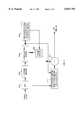
- FIG. 3is a functional block diagram of the preprocessing portion of the digital image processor of the present invention.
- FIG. 4is a functional block diagram of the detection and tracking portion of the digital image processor of the present invention.
- FIGS. 5 and 5aillustrate the manner in which image pixels of a 2D delineated zone of a roadway lane are integrated into a 1D strip.
- the present inventioncomprises at least one video camera for deriving successive image frames of road traffic and a traffic-monitoring image processor for digitally processing the pixels of the successive image frames.
- the output of video camera 100may be directly applied as an input to traffic-monitoring image processor 102 for digitally processing the pixels of the successive image frames in real time.
- the output of video camera 100may be first recorded by VCR 104 and then, at a later time, the pixels of the successive image frames may be readout of the VCR and applied as an input to traffic-monitoring image processor 102 for digitally processing the pixels of the successive image frames.
- Video camera 100which may be CCD camera or an IR camera which is mounted at a given height over a roadway and which has a given field of view of a given length segment of the roadway. As shown in FIGS. 2a and 2b, video camera 100, by way of example, may be mounted 30 feet above the roadway and have a 62° field of view sufficient to view a 60 foot width (5 lanes) of a length segment of the roadway extending from 50 feet to 300 feet with respect to the projection of the position of video camera 100 on the roadway.
- FIG. 2cshows that video camera 100 derives a 640 ⁇ 480 pixel image of the portion of the roadway within its field of view. For illustrative purposes, vehicular traffic normally present on the length segment of the roadway has been omitted from the FIG. 2c image.
- video camera 100was one of a group of four time-divided cameras each of which operated at a frame rate of 7.5 frames per second.
- a principal purpose of the present inventionis to be able to provide a computationally-efficient digital traffic-monitoring image processor that is capable of more accurately detecting, counting and tracking vehicular traffic traveling over the viewed given length segment of the roadway than was heretofore possible. For instance, consider the following four factors which tend to result in detecting, and tracking errors or in decreasing computational efficiency:
- a vehiclemust be detected based on its contrast relative to the background road surface. This contrast can be low when the vehicle has a reflected light intensity similar to that of the road. Detection errors are most likely under low light conditions, and on gray, overcast days. The system may then miss some vehicles, or, if the threshold criteria for detection are low, the system may mistake some background patterns, such as road markings, as vehicles.
- Shadows or cause headlight reflections that may cross neighboring laneswill often have greater contrast than the vehicles themselves.
- Prior art type traffic monitoring systemsmay then interpret shadows as additional vehicles, resulting in an over count of traffic flow. Shadows of large vehicles, such as trucks, may completely overlap smaller cars or motor cycles, and result in the overshadowed vehicles not being counted. Shadows may also be cast by objects that are not within the roadway, such as trees, building, and clouds. And they can be cast by vehicles going the other direction on another roadway. Again, such shadows may be mistaken as additional vehicles.
- a camera that is mounted on a utility polemay move as the pole sways in a wind.
- a camera mounted on a highway bridgemay vibrate when trucks pass over the bridge. In either case camera motion results in image motion and that cause detection and tracking errors. For example, camera sway becomes a problem if it causes the detection process to confuse one road lane with another, or if it causes a stationary vehicle to appear to move.
- the present inventionis directed to a digital traffic-monitoring image processor that includes means for overcoming one or more of these four problems.
- FIG. 3there is shown a functional block diagram of a preferred embodiment of a preprocessor portion digital traffic-monitoring image processor 102. Shown in FIG. 3 are analog-to-digital (A/D) converter 300, pyramid means 302, stabilization means 304, reference image derivation and updating means 306, frame store 308, reference image modifying means 310 and subtractor 312.
- A/Danalog-to-digital
- the analog video signal input from camera 100 or VCR 104after being digitized by A/D 300, may be decomposed into a specified number of Gaussian pyramid levels by pyramid means 302 for reducing pixel density and image resolution.
- Pyramid means 302is not essential, since the vehicular traffic system could be operated at the resolution of the 640 ⁇ 480 pixel density of video camera 100. However, because this resolution is higher than is needed downstream for the present vehicular traffic system, the use of pyramid means 302 increases the system's computational efficiency. Not all levels of the pyramid must be used in each computation. Further, not all levels of the pyramid need be stored between computations, as higher levels can always be computed from lower ones. However, for illustrative purposes it is assumed that all of the specified number of Gaussian pyramid levels are available for each of the downstream computations discussed below.
- Stabilization means 304employs electronic image stabilization to compensate for the problem of camera sway, in which movement may be induced by wind or a passing truck. Camera motion causes pixels in the image to move. Prior art vehicular traffic systems that do not compensate for camera motion will produce false positive detections if the camera moves so that the image of a surface marking or a car in an adjacent lane overlaps a detection zone. Stabilization means 304 compensates for image translation from frame to frame that is due to camera rotation about an axis perpendicular to the direction of gaze.
- the compensationis achieved by shifting the current image an integer number of rows and columns so that, despite camera sway, it remains fixed in alignment to within one pixel with a reference image derived by means 306 and stored within frame store 308.
- the required shiftis determine by locating two known landmark features in each frame. This is done via a matched filter.
- reference image derivation and updating means 306generates an original reference image r 0 simply by blurring the first-occurring image frame i 0 applied as an input thereto from means 304 with a large Gaussian filter (so that reference image r 0 may comprise a higher pyramid level), and then reference image r 0 is stored in frame store 308. Following this, the image stored in frame store 308 is updated during a first initialization phase by means 306.
- means 306performs a recursive temporal filtering operation on each corresponding pixel of the first few image frames of successive stabilized image frames applied as an input thereto from means 304 with the additional constraint that if the difference between the reference image and the current image is too large, the reference image is not updated at that pixel.
- r trepresents the reference image after frame t
- i trepresents the t'th frame of the input image frame sequence from means 304.
- the constant ⁇determines the "responsiveness" of the construction process.
- the "responsiveness" setting of ⁇must be sufficiently slow to keep transitory objects, such as moving vehicles or even vehicles that may be temporarily stopped by a traffic jam, out of the reference image, so that, at the end of the first few input image frames to means 306 which comprise the first initialization phase, the stored reference image in frame store 308 will comprise only the stationary background objects being viewed by camera 100.
- Such a "responsiveness" setting of ⁇is incapable of adjusting r t quickly enough to add illumination changes (such as those due to a passing cloud or the auto-iris on camera 100) to the reference image.
- This problemis solved at the end of the initialization phase by the cooperative updating operation of reference image modifying means 310 (which comprises an illumination/AGC compensator) with that of means 306 and frame store 308.
- k t and c tare the estimated gain and offset between the reference image r t and the current image i t computed by means 310.
- Means 310computes this gain and offset by plotting a cloud of points in a 2D space in which the x-axis represents gray-level intensity in the reference image, and the y-axis represents gray-level intensity in the current image, and fitting a line to this cloud.
- the cloudis the set of points (r t-1 (x,y),i t (x,y)) for all image positions x,y.
- the gainmight be estimated by comparing the histograms of the current image and the reference image.
- the specific update rulesneed not use an absolute threshold D as described above. Instead, the update could be weighted by any function of
- the above approachallows fast illumination changes to be added to the reference image while preventing transitory objects from being added. It does so by giving the cooperative means the flexibility to decide whether the new reference image pixel values should be computed as a function of pixel values in the current image or whether they should be computed simply by applying a gain and offset to the current reference image. By applying a gain and offset to the current reference image the illumination change can be simulated without running the risk of allowing transitory objects to appear in the reference image.
- subtractor 312which computes the difference between the amplitudes of corresponding pixels applied as inputs thereto from means 310 and 304, derives an output made up of significantly-valued pixels that manifest solely moving object (i.e., vehicular traffic) in each one of successive 2D image frames.
- the output of subtractor 312is forwarded to the detection and tracking portion of traffic-monitoring image processor 102 shown in FIG. 4.
- 2D/1D converter 400there is shown 2D/1D converter 400, vehicle fragment detector 402, image-flow estimator 404, single frame delay 406, pixel-amplitude squaring means 408, vehicle hypothesis generator 410 and shadow and reflected headlight filter 412.
- FIG. 5shows an image frame 500 derived by camera 100 of straight, 5-lane roadway 502 with cars 504-1 and 504-2 traveling on the second lane 506 from the left. Cars 504-1 and 504-2 are shown situated within an image zone 508 delineated by the aforesaid user control information applied as a second input to converter 400.
- 1D strip 510is computed by converter 400.
- the roadwayneed not be straight.
- curved roadway lane 512includes zone 514 defined by user-delineated lane boundaries 516 which permits the computation of medial strip 518 by converter 400.
- the usermay employ lane-defining stripes that may be present in the image as landmarks for help in defining the user-delineated lane boundaries.
- computation by converter 400involves employing each of pixel positions (x, y) to define integration windows.
- a windowmight be either (a) all image pixels on row y that are within the delineated lane bounds, (b) all image pixels on column x that are within the delineated lane bounds, or (c) all image pixels on a line perpendicular to the tangent of the medial strip at position (x, y).
- Other types of integration windows not described heremay also be used.
- the 1D output from converter 400is applied as an input to detector 402, estimator 404 and single frame delay 406, and through means 408 to filter 408. While the respective detection, tracking and filtering functions performed by these elements are independent of whether they operate on 1D or 2D signals, 1D operation is to be preferred because it significantly reduces computational requirements. Therefore, the presence of converter 400, while desirable, is not essential to the performance of these detection, tracking and filtering functions. In the following discussion, it is assumed that converter 400 is present
- Detector 402preferably utilizes a multi-level pyramid to provide a coarse-to-fine operation to detect the presence and spatial location of vehicle fragments in the 1D strip of successive image frames received from FIG. 3.
- a fragmentis defined as a group of significantly-valued pixels at any pyramid level that are connected to one another.
- Detector 402is tuned to maximize the chances that each vehicle will give rise to a single fragment. However, in practice this is impossible to achieve; each vehicle gives rise to multiple fragments (such as separate fragments corresponding to the hood, roof and headlights of the same vehicle). Further, pixels of more than one vehicle may be connected into a single fragment.
- One technique for object detection at each strip pixel positionis to compute a histogram of the image intensity values within the integration window centered at that pixel position. Based on attributes of this histogram (e.g., the number or percentage of pixels over some threshold value or values), classify that strip pixel as either "detection” or "background". By performing this operation at each strip pixel, one can construct a one-dimensional array that contains, for each pixel position, the "detection" or "background” label. By performing connected component analysis within this array, adjacent "detection" pixels can be grouped into “fragments”.
- attributes of this histograme.g., the number or percentage of pixels over some threshold value or values
- Image-flow estimator 404in cooperation with delay 406, which employs the teachings of the aforesaid Bergen et al. article, to permit objects to be tracked over time. Briefly, in this case, this involves, at each pixel position, computing and storing the average value contained within the integration window. By performing this operation at each strip pixel, a one-dimensional array of average brightness values is constructed. Given two corresponding arrays for images taken at times t-1 and t, the one-dimensional image "flow" that maps pixels in one array to the other is computed. This can be computed via one-dimensional least-squares minimization or one-dimensional patchwise correlation. This flow information can be used to track objects between each pair of successive image frames.
- the respective outputs of detector 402 and estimator 404are applied as inputs to vehicle hypothesis generator 410.
- Nearby fragmentsare grouped together as part of the same object (i.e., vehicle) if they move in similar ways or are sufficiently close together. If the positions of multiple fragments remain substantially fixed with respect to one another in each of a train of successive frames, they are assumed to indicate only a single vehicle. However, if the positions of the fragments change from frame to frame, they are assumed to indicate separate vehicles. Further, if a single fragment of in one frame breaks up into multiple fragments or significantly stretches out longitudinally in shape from one frame to another, they are also assumed to indicate separate vehicles.
- Headlightstend to produce headlight reflections on the road.
- Shadow and reflected headlight filter 412which discriminates between fragments that produced by valid vehicles and those produced by shadows and reflected headlights, eliminates such false positive error.
- the output from pixel-amplitude squaring means 408manifests the relative energy in each pyramid-level pixel of the strip output of each of successive image frames from converter 400.
- Filter 412discriminates between fragments that produced by valid vehicles and those produced by shadows and reflected headlights based on an analysis of the relative amplitudes of these energy-manifesting pixels from means 408. The fact that the variance in energy pixel amplitude (pixel brightness) of shadow and reflected headlight fragments is significantly less than that of valid vehicle fragments can be used as a discriminant.
- Another way of filteringis to employ converter 400 for discriminating between objects and shadows using the background-adjusted reference image. At each pixel position, the following information is computed over the integration window:
- Fragments that have been extracted as described previouslycan be classified as object or shadow based on these or other properties. For example, if the value of measure (a), summed over all strip pixels within the fragment, exceeds some threshold, then the fragment cannot be a shadow (since shadows would never have positive brightness values in the images applied to converter 400 from FIG. 3.
- a similar summation using measure (c)provides another test measuring the amount of texture within the fragment, which can also be thresholded to determine whether a fragment is an object or a shadow. While the input to filter 412 defines all hypothesized vehicle locations, the output therefrom defines only verified vehicle locations. The output from filter 412 is forwarded to utilization means (not shown) which may perform such functions as counting the number of vehicles and computing their velocity and length.
- Vehicle fragment detector 402, image-flow eatimator 404, and vehicle hypothesis generator 410may use pre-determined camera calibration information in their operation. Further, each of the various techniques of the present invention described above may also be employed to advantage in other types of imaging systems from the vehicular traffic monitoring system disclosed herein.
Landscapes
- Engineering & Computer Science (AREA)
- Physics & Mathematics (AREA)
- General Physics & Mathematics (AREA)
- Theoretical Computer Science (AREA)
- Multimedia (AREA)
- Computer Vision & Pattern Recognition (AREA)
- Image Analysis (AREA)
- Image Processing (AREA)
- Closed-Circuit Television Systems (AREA)
- Traffic Control Systems (AREA)
Abstract
Description
This is a continuation of application Ser. No. 08/372,924 filed on Jan. 17, 1995 abandoned.
1. Field of the Invention
The invention relates to a vehicular traffic monitoring system and, more particularly, to such a system that digitally processes pixels of successive image frames derived from a video camera viewing road traffic.
2. Description of the Prior Art
Various types of traffic monitoring systems are known in the prior art and examples thereof are respectively disclosed in U.S. Pat. Nos. 4,433,325, 4,847,772, 5,161,107 and 5,313,295. However, there is a need for a more robust traffic monitoring system that is computationally efficient and yet is relatively inexpensive to implement.
Further, the present invention makes use of pyramid teachings disclosed in U.S. Pat. No. 4,692,806, which issued to Anderson et al. on September 8, and image flow teachings disclosed in the article "Hierarchical Model-Based Motion Estimation" by Bergen et al., appearing in the Proceedings of the European Conference on Computer Vision, Springer-Verlag, 1992. Both of these teachings are incorporated herein by reference.
The invention relates to an improvement in digital image processing means of a vehicular traffic monitoring system that includes a video camera having a given field of view for recording successive image frames of road traffic within its field of view. The digital image processing means, is responsive to pixel information defined by each of the successive image frames.
Specifically, the digital image processing means comprises first means responsive to an initial train of the successive image frames for deriving a stored initial reference image defining only stationary objects within the field of view and thereafter updating the stored initial reference image with a reference image derived from an image frame recorded later than the initial train, with each pixel's digital amplitude level of each of the reference images being determined by illumination conditions existing when the initial train and when the later recorded frame were recorded; second means for modifying each pixel's digital amplitude level of one of a current image frame and the stored reference image then being stored to make their corresponding pixels defining stationary objects substantially equal to one another; third means responsive to the digital amplitude-level difference between corresponding pixels of each of successively occurring ones of the successive image frames and the then stored reference image for deriving successive images defining only moving objects within the field of view; fourth means for discriminating between those moving objects that remain substantially fixed in position with respect to one another in each of the successively-occurring ones of the successively-occurring images and those moving objects that substantially change in position with respect to one another in each of the successively-occurring ones of the successively-occurring images; and fifth means responsive to the variance of the digital amplitude levels of the pixels of those ones of the objects that remain substantially fixed in position with respect to one another for distinguishing and then eliminating those ones of the moving objects that remain substantially fixed in position with respect to one another that define non-physical moving objects, such as shadows and headlight reflections cast by physical moving objects, from the moving objects that remain substantially fixed in position with respect to one another that define the physical moving objects.
FIGS. 1a and 1b show alternative real time and non-real time ways of coupling a video camera to a traffic-monitoring image processor;
FIGS. 2a, 2b and 2c relate to the image field of a video camera viewing a multi-lane roadway;
FIG. 3 is a functional block diagram of the preprocessing portion of the digital image processor of the present invention;
FIG. 4 is a functional block diagram of the detection and tracking portion of the digital image processor of the present invention; and
FIGS. 5 and 5a illustrate the manner in which image pixels of a 2D delineated zone of a roadway lane are integrated into a 1D strip.
The present invention comprises at least one video camera for deriving successive image frames of road traffic and a traffic-monitoring image processor for digitally processing the pixels of the successive image frames. As shown in FIG. 1a, the output ofvideo camera 100 may be directly applied as an input to traffic-monitoring image processor 102 for digitally processing the pixels of the successive image frames in real time. Alternatively, as shown in FIG. 1b, the output ofvideo camera 100 may be first recorded by VCR 104 and then, at a later time, the pixels of the successive image frames may be readout of the VCR and applied as an input to traffic-monitoring image processor 102 for digitally processing the pixels of the successive image frames.
In a designed vehicular traffic monitoring system,video camera 100 was one of a group of four time-divided cameras each of which operated at a frame rate of 7.5 frames per second.
A principal purpose of the present invention is to be able to provide a computationally-efficient digital traffic-monitoring image processor that is capable of more accurately detecting, counting and tracking vehicular traffic traveling over the viewed given length segment of the roadway than was heretofore possible. For instance, consider the following four factors which tend to result in detecting, and tracking errors or in decreasing computational efficiency:
1. Low Contrast
A vehicle must be detected based on its contrast relative to the background road surface. This contrast can be low when the vehicle has a reflected light intensity similar to that of the road. Detection errors are most likely under low light conditions, and on gray, overcast days. The system may then miss some vehicles, or, if the threshold criteria for detection are low, the system may mistake some background patterns, such as road markings, as vehicles.
2. Shadows and Headlight Reflections
At certain times of day vehicles will cast shadows or cause headlight reflections that may cross neighboring lanes. Such shadows or headlight reflections will often have greater contrast than the vehicles themselves. Prior art type traffic monitoring systems may then interpret shadows as additional vehicles, resulting in an over count of traffic flow. Shadows of large vehicles, such as trucks, may completely overlap smaller cars or motor cycles, and result in the overshadowed vehicles not being counted. Shadows may also be cast by objects that are not within the roadway, such as trees, building, and clouds. And they can be cast by vehicles going the other direction on another roadway. Again, such shadows may be mistaken as additional vehicles.
3. Camera Sway
A camera that is mounted on a utility pole may move as the pole sways in a wind. A camera mounted on a highway bridge may vibrate when trucks pass over the bridge. In either case camera motion results in image motion and that cause detection and tracking errors. For example, camera sway becomes a problem if it causes the detection process to confuse one road lane with another, or if it causes a stationary vehicle to appear to move.
4. Computational Efficiency
Since vehicle travel is confined to lanes and normal travel direction is one dimensional along the length of a lane, it is computationally inefficient to employ two-dimensional image processing in detecting and tracking vehicular traffic.
The present invention is directed to a digital traffic-monitoring image processor that includes means for overcoming one or more of these four problems.
Referring to FIG. 3, there is shown a functional block diagram of a preferred embodiment of a preprocessor portion digital traffic-monitoring image processor 102. Shown in FIG. 3 are analog-to-digital (A/D)converter 300, pyramid means 302, stabilization means 304, reference image derivation and updating means 306,frame store 308, reference image modifying means 310 andsubtractor 312.
The analog video signal input fromcamera 100 or VCR 104, after being digitized by A/D 300, may be decomposed into a specified number of Gaussian pyramid levels by pyramid means 302 for reducing pixel density and image resolution. Pyramid means 302 is not essential, since the vehicular traffic system could be operated at the resolution of the 640×480 pixel density ofvideo camera 100. However, because this resolution is higher than is needed downstream for the present vehicular traffic system, the use of pyramid means 302 increases the system's computational efficiency. Not all levels of the pyramid must be used in each computation. Further, not all levels of the pyramid need be stored between computations, as higher levels can always be computed from lower ones. However, for illustrative purposes it is assumed that all of the specified number of Gaussian pyramid levels are available for each of the downstream computations discussed below.
The first of these downstream computations is performed by stabilization means 304. Stabilization means 304 employs electronic image stabilization to compensate for the problem of camera sway, in which movement may be induced by wind or a passing truck. Camera motion causes pixels in the image to move. Prior art vehicular traffic systems that do not compensate for camera motion will produce false positive detections if the camera moves so that the image of a surface marking or a car in an adjacent lane overlaps a detection zone. Stabilization means 304 compensates for image translation from frame to frame that is due to camera rotation about an axis perpendicular to the direction of gaze. The compensation is achieved by shifting the current image an integer number of rows and columns so that, despite camera sway, it remains fixed in alignment to within one pixel with a reference image derived bymeans 306 and stored withinframe store 308. The required shift is determine by locating two known landmark features in each frame. This is done via a matched filter.
The problem of low contrast is overcome by the cooperative operation of reference image derivation and updating means 306,frame store 308 and referenceimage modifying means 310.Means 306 generates an original reference image r0 simply by blurring the first-occurring image frame i0 applied as an input thereto from means 304 with a large Gaussian filter (so that reference image r0 may comprise a higher pyramid level), and then reference image r0 is stored inframe store 308. Following this, the image stored inframe store 308 is updated during a first initialization phase bymeans 306. More specifically, means 306 performs a recursive temporal filtering operation on each corresponding pixel of the first few image frames of successive stabilized image frames applied as an input thereto from means 304 with the additional constraint that if the difference between the reference image and the current image is too large, the reference image is not updated at that pixel. Put mathematically, ##EQU1## where rt represents the reference image after frame t, and it represents the t'th frame of the input image frame sequence from means 304. The constant γ determines the "responsiveness" of the construction process.
The "responsiveness" setting of γ must be sufficiently slow to keep transitory objects, such as moving vehicles or even vehicles that may be temporarily stopped by a traffic jam, out of the reference image, so that, at the end of the first few input image frames to means 306 which comprise the first initialization phase, the stored reference image inframe store 308 will comprise only the stationary background objects being viewed bycamera 100. Such a "responsiveness" setting of γ is incapable of adjusting rt quickly enough to add illumination changes (such as those due to a passing cloud or the auto-iris on camera 100) to the reference image. This problem is solved at the end of the initialization phase by the cooperative updating operation of reference image modifying means 310 (which comprises an illumination/AGC compensator) with that ofmeans 306 andframe store 308. Specifically, when the initialization phase is completed, it is replaced by a second normal operating phase which operates in accordance with the following equation 2 (rather than the above equation 1): ##EQU2## where kt and ct, are the estimated gain and offset between the reference image rt and the current image it computed bymeans 310.Means 310 computes this gain and offset by plotting a cloud of points in a 2D space in which the x-axis represents gray-level intensity in the reference image, and the y-axis represents gray-level intensity in the current image, and fitting a line to this cloud. The cloud is the set of points (rt-1 (x,y),it (x,y)) for all image positions x,y. This approach will work using any method for computing the gain and offset representing illumination change. For example, the gain might be estimated by comparing the histograms of the current image and the reference image. Also, the specific update rules need not use an absolute threshold D as described above. Instead, the update could be weighted by any function of |it (x,y)-rt-1,(x,y)|.
The above approach allows fast illumination changes to be added to the reference image while preventing transitory objects from being added. It does so by giving the cooperative means the flexibility to decide whether the new reference image pixel values should be computed as a function of pixel values in the current image or whether they should be computed simply by applying a gain and offset to the current reference image. By applying a gain and offset to the current reference image the illumination change can be simulated without running the risk of allowing transitory objects to appear in the reference image.
The result is that the amplitude of the stationary background manifesting pixels of the illumination-compensated current image appearing at the output of means 310 (which includes both stationary background manifesting pixels and moving object (i.e., vehicular traffic)) will always be substantially equal to the amplitude of the stationary background manifesting pixels of the reference image (which includes solely stationary background manifesting pixels) appearing at the output offrame store 308. Therefore,subtractor 312, which computes the difference between the amplitudes of corresponding pixels applied as inputs thereto frommeans 310 and 304, derives an output made up of significantly-valued pixels that manifest solely moving object (i.e., vehicular traffic) in each one of successive 2D image frames. The output ofsubtractor 312 is forwarded to the detection and tracking portion of traffic-monitoring image processor 102 shown in FIG. 4.
Referring to FIG. 4, there is shown 2D/1D converter 400,vehicle fragment detector 402, image-flow estimator 404,single frame delay 406, pixel-amplitude squaring means 408,vehicle hypothesis generator 410 and shadow and reflectedheadlight filter 412.
2D/1D converter 400 operates to convert 2D image information received from FIG. 3 that is applied as a first input thereto into 1D image information in accordance with user control information applied as a second input thereto. In this regard, reference is made to FIGS. 5 and 5a. FIG. 5 shows animage frame 500 derived bycamera 100 of straight, 5-lane roadway 502 with cars 504-1 and 504-2 traveling on thesecond lane 506 from the left. Cars 504-1 and 504-2 are shown situated within animage zone 508 delineated by the aforesaid user control information applied as a second input toconverter 400. By integrating horizontally the amplitudes of the pixels across image zone and then subsampling the vertically oriented integrated pixel amplitudes along the center ofzone 1D strip 510 is computed byconverter 400. The roadway need not be straight. As shown in FIG. 5a,curved roadway lane 512 includeszone 514 defined by user-delineatedlane boundaries 516 which permits the computation ofmedial strip 518 byconverter 400. In both FIGS. 5 and 5a, the user may employ lane-defining stripes that may be present in the image as landmarks for help in defining the user-delineated lane boundaries.
More specifically, computation byconverter 400 involves employing each of pixel positions (x, y) to define integration windows. For example, such a window might be either (a) all image pixels on row y that are within the delineated lane bounds, (b) all image pixels on column x that are within the delineated lane bounds, or (c) all image pixels on a line perpendicular to the tangent of the medial strip at position (x, y). Other types of integration windows not described here may also be used.
The 1D output fromconverter 400 is applied as an input todetector 402,estimator 404 andsingle frame delay 406, and throughmeans 408 to filter 408. While the respective detection, tracking and filtering functions performed by these elements are independent of whether they operate on 1D or 2D signals, 1D operation is to be preferred because it significantly reduces computational requirements. Therefore, the presence ofconverter 400, while desirable, is not essential to the performance of these detection, tracking and filtering functions. In the following discussion, it is assumed thatconverter 400 is present
One technique for object detection at each strip pixel position is to compute a histogram of the image intensity values within the integration window centered at that pixel position. Based on attributes of this histogram (e.g., the number or percentage of pixels over some threshold value or values), classify that strip pixel as either "detection" or "background". By performing this operation at each strip pixel, one can construct a one-dimensional array that contains, for each pixel position, the "detection" or "background" label. By performing connected component analysis within this array, adjacent "detection" pixels can be grouped into "fragments".
Image-flow estimator 404 in cooperation withdelay 406, which employs the teachings of the aforesaid Bergen et al. article, to permit objects to be tracked over time. Briefly, in this case, this involves, at each pixel position, computing and storing the average value contained within the integration window. By performing this operation at each strip pixel, a one-dimensional array of average brightness values is constructed. Given two corresponding arrays for images taken at times t-1 and t, the one-dimensional image "flow" that maps pixels in one array to the other is computed. This can be computed via one-dimensional least-squares minimization or one-dimensional patchwise correlation. This flow information can be used to track objects between each pair of successive image frames.
The respective outputs ofdetector 402 andestimator 404 are applied as inputs tovehicle hypothesis generator 410. Nearby fragments are grouped together as part of the same object (i.e., vehicle) if they move in similar ways or are sufficiently close together. If the positions of multiple fragments remain substantially fixed with respect to one another in each of a train of successive frames, they are assumed to indicate only a single vehicle. However, if the positions of the fragments change from frame to frame, they are assumed to indicate separate vehicles. Further, if a single fragment of in one frame breaks up into multiple fragments or significantly stretches out longitudinally in shape from one frame to another, they are also assumed to indicate separate vehicles.
At night, the presence of a vehicle may be indicated only by its headlights. Headlights tend to produce headlight reflections on the road.
Lighting conditions on the road during both day and night tend to cause vehicle shadows on the road. Both such shadows and headlight reflections on the road result in producing detected fragments that will appear togenerator 410 as additional vehicles, thereby creating false positive error in the output fromgenerator 410. Shadow and reflectedheadlight filter 412, which discriminates between fragments that produced by valid vehicles and those produced by shadows and reflected headlights, eliminates such false positive error.
The output from pixel-amplitude squaring means 408 manifests the relative energy in each pyramid-level pixel of the strip output of each of successive image frames fromconverter 400.Filter 412 discriminates between fragments that produced by valid vehicles and those produced by shadows and reflected headlights based on an analysis of the relative amplitudes of these energy-manifesting pixels frommeans 408. The fact that the variance in energy pixel amplitude (pixel brightness) of shadow and reflected headlight fragments is significantly less than that of valid vehicle fragments can be used as a discriminant.
Another way of filtering, not shown in FIG. 4, is to employconverter 400 for discriminating between objects and shadows using the background-adjusted reference image. At each pixel position, the following information is computed over the integration window:
(a) the number of pixels with brightness value greater than some threshold p, over all image pixels within the integration window
(b) the maximum absolute value, over all image pixels within the integration window
(c) the number of adjacent pixels (x1, y1, and (x2, y2) within the integration window whose absolute difference, |I(x1, y1)-I(x2, y2)|, exceeded a threshold value.
Fragments that have been extracted as described previously can be classified as object or shadow based on these or other properties. For example, if the value of measure (a), summed over all strip pixels within the fragment, exceeds some threshold, then the fragment cannot be a shadow (since shadows would never have positive brightness values in the images applied toconverter 400 from FIG. 3. A similar summation using measure (c) provides another test measuring the amount of texture within the fragment, which can also be thresholded to determine whether a fragment is an object or a shadow. While the input to filter 412 defines all hypothesized vehicle locations, the output therefrom defines only verified vehicle locations. The output fromfilter 412 is forwarded to utilization means (not shown) which may perform such functions as counting the number of vehicles and computing their velocity and length.
Claims (40)
1. In a vehicular traffic monitoring system including a video camera having a given field of view for recording successive image frames of road traffic within its field of view, and digital image processing means responsive to pixel information defined by each of said successive image frames; the improvement wherein said digital image processing means comprises:
first means responsive to an initial train of said successive image frames for deriving a stored initial reference image defining only stationary objects within said field of view and thereafter updating said stored initial reference image with a reference image derived from an image frame recorded later than said initial train, with each pixel's digital amplitude level of each of said reference images being determined by illumination conditions existing when said initial train and when said later recorded frame were recorded;
second means for modifying each pixel's digital amplitude level of one of a current image frame and said stored reference image then being stored to make their corresponding pixels defining stationary objects substantially equal to one another;
third means responsive to the digital amplitude-level difference between corresponding pixels of each of successively-occurring ones of said successive image frames and the then stored reference image for deriving successive images defining only moving objects within said field of view;
fourth means for discriminating between those moving objects that remain substantially fixed in position with respect to one another in each of said successively-occurring ones of said successively-occurring images and those moving objects that substantially change in position with respect to one another in each of said successively-occurring ones of said successively-occurring images; and
a fifth means responsive to the variance of the digital amplitude levels of the pixels of those ones of said objects that remain substantially fixed in position with respect to one another for distinguishing those ones of said moving objects that remain substantially fixed in position with respect to one another that define non-physical moving objects, from said moving objects that remain substantially fixed in position with respect to one another that define physical moving objects, and then eliminating those ones of said moving objects that define non-physical moving objects.
2. The vehicular traffic monitoring system defined in claim 1, wherein said video camera is subject to camera sway, and wherein said digital image processing means further comprises:
electronic image stabilization means for compensating for image translation due to camera sway.
3. The vehicular traffic monitoring system defined in claim 2, wherein:
said electronic image stabilization means employs two known landmarks in each successive image frame to shift the current image that first number of rows and that second number of columns which result in said current image remaining substantially in alignment with said reference image.
4. The vehicular traffic monitoring system defined in claim 1, wherein said video camera records successive two-dimensional image frames of road traffic within its field of view, and wherein said digital image processing means further comprises:
sixth means employing pixel integration windows for converting each frame derived by said third means of said successive images that define only moving objects within said field of view from a two-dimensional image frame to a one-dimensional image frame that is substantially oriented in the direction of said road traffic.
5. The vehicular traffic monitoring system defined in claim 1, wherein:
said first means and said second means cooperate during the occurrence of said initial train of said successive image frames in accordance with a first set of equations ##EQU3## and thereafter said first and second means cooperate in accordance with a second set of equations ##EQU4## where (x,y) represents the coordinates of each pixel in an image frame, rt represents the reference image after frame t, and it represents the t'th frame of the successive image frames, D represents a predetermined difference between the amplitude level of each pair of corresponding pixels of it and rt, k and ct respectively represent a single pair of estimated gain and offset values in amplitude level for the pixels of one of it and rt which results in corresponding pixels of it and rt which reduces the statistical error in the respective differences in amplitude levels between corresponding pixels of it and rt, and γ is a constant that determines the responsiveness of the cooperation of said first and second means both during the occurrence of said initial train of said successive image frames and thereafter.
6. The vehicular traffic monitoring system defined in claim 5, wherein: k and ct respectively represent that single pair of estimated gain and offset in amplitude level of the pixels of one of it and rt which minimizes the statistical error in the respective differences in amplitude levels between corresponding pixels of it and rt.
7. A method of image processing comprising the steps of:
(a) supplying a first sequence of image frames;
(b) initializing a reference image that contains image information regarding stationary objects within a scene represented by said first sequence of images;
(c) supplying a next image frame which temporally follows said first sequence of image frames;
(d) comparing said next image frame to said reference image to produce a two-dimensional motion image representing motion information regarding movement of objects within the scene;
(e) updating said reference image with information within said next image frame, where said information used for updating the reference image only represents stationary objects within the scene and substantially disregards moving objects and temporarily stationary objects within the scene; and
(f) repeating steps (c), (d), and (e) for each next image supplied.
8. The method of claim 7 further comprising the step of stabilizing each image frame to remove any motion within said image frames that occurs due to imaging sensor movement rather than object movement within the scene.
9. The method of claim 7 wherein said updating step comprises the steps of:
selecting a pixel value in the reference image and a pixel value in the next image frame having the same pixel location as the selected pixel value in the reference image;
computing a difference factor equal to the absolute value of the difference between said selected pixel value in the next image frame and said pixel value in the reference image;
comparing the difference value to a first threshold value;
if said difference value is less than said first threshold value, replacing the pixel value in the reference image with an updated reference pixel value equaling the selected reference image pixel value altered by an update factor; and
if said difference value is greater than or equal to said first threshold value, the pixel value in said reference image remains the same.
10. The method of claim 9 wherein said update factor is the difference between said selected pixel value in the next image and said pixel value in the reference image multiplied by a responsiveness factor, where said responsiveness factor limits the amount of the update to ensure that the updated reference image only contains information regarding information within said next image frame that represents stationary objects within the scene.
11. The method of claim 9 wherein said first threshold value is a function of the difference factor.
12. The method of claim 7 wherein said method further comprises the step of modifying said reference image using image information within said next image frame regarding changes to illumination of the scene.
13. The method of claim 12 wherein said modifying step comprises the steps of:
selecting a pixel value in the reference image and a pixel value in the next image frame having the same pixel location as the selected reference image pixel value;
computing a difference factor equal to the absolute value of the difference between said selected pixel value in the next image and said pixel value in the reference image;
comparing the difference value to a second threshold value;
if said difference value is less than said second threshold value, replacing the pixel value in the reference image with a modified reference pixel value equaling the selected reference image pixel value altered by a modifying factor; and
if said difference value is greater than or equal to said second threshold value, the selected reference image pixel value is replaced with a new reference image pixel value equal to a weighted and scaled selected reference image pixel value.
14. The method of claim 13 wherein said modifying factor is the difference between said selected pixel value in the next image frame and said selected pixel value in the reference image multiplied by a responsiveness factor, where said responsiveness factor limits the amount of the modification to ensure that the modified reference image only contains information regarding information within said next image frame that represents stationary objects within the scene and where said weighted and scaled selected reference image pixel value represents illumination changes within said scene.
15. The method of claim 13 wherein said second threshold value is a function of the difference factor.
16. The method of claim 7 further comprising the step of converting the two-dimensional motion image into a one-dimensional data set.
17. The method of claim 16 wherein the converting step further comprises the steps of:
defining a zone within said two-dimensional motion image containing a plurality of rows of pixel values;
integrating the pixel values across each said row of pixel values within said zone to produce an integrated pixel value for each of said rows of pixel values; and
subsampling said integrated pixel values to produce said one-dimensional data set.
18. The method of claim 17 further comprising the steps of:
detecting object fragments within said one dimensional data set, where said object fragments are a group of significantly-valued integrated pixel values that are adjacent one another;
estimating object motion of said object fragments between two consecutive next image frames; and
identifying objects within the zone in response to the estimated object motion of said object fragments.
19. The method of claim 18 further comprising the step of filtering said identified objects to eliminate erroneous moving object identifications.
20. The method of claim 19 wherein said filtering step comprises:
identifying the pixels within the zone having a brightness value greater than a brightness threshold as bright pixels;
computing a maximum absolute value of the pixel values within the zone;
identifying the adjacent pixels within the zone having an absolute difference of pixel values that exceeds an absolute difference threshold as intense valued pixels;
using the bright pixels, the maximum absolute value and the intense values pixels to eliminate moving object identifications that represent movement of non-physical objects within the zone.
21. The method of claim 7 further comprising the steps of:
detecting object fragments within said two-dimensional motion image, where said object fragments are a group of significantly-valued integrated pixel values that are adjacent one another;
estimating object motion of said object fragments between two consecutive next image frames; and
identifying objects within the scene in response to the estimated object motion of said object fragments.
22. The method of claim 21 further comprising the step of filtering said identified objects to accurately identify physical moving objects and eliminate non-physical moving object identifications.
23. The method of claim 22 wherein said filtering step comprises:
identifying the pixels within the two-dimensional motion image having a brightness value greater than a brightness threshold as bright pixels;
computing a maximum absolute value of the pixel values within the two-dimensional motion image;
identifying the adjacent pixels within the two-dimensional motion image having an absolute difference of pixel values that exceeds an absolute difference threshold as intense valued pixels;
using the bright pixels, the maximum absolute value and the intense valued pixels to eliminate non-physical moving objects from the identified moving objects.
24. Apparatus for image processing comprising:
imaging means for supplying a continuous sequence of image frames representing a scene;
reference image initializing means, connected to said imaging means, for initializing a reference image that contains image information regarding stationary objects within the scene;
comparator means, connected to said imaging means and said reference image initializing means, for comparing an image frame supplied by said imaging means to said reference image to produce a two-dimensional motion image representing motion information regarding movement of objects within the scene;
means for updating said reference image with information within said image frame, where said information used for updating the reference image only represents stationary objects within the scene and substantially disregards moving objects and temporarily stationary objects within the scene.
25. The apparatus of claim 24 further comprising stabilization means, connected to said imaging means, for stabilizing each image frame to remove any motion within said image frames that occurs due to imaging means movement rather than object movement within the scene.
26. The apparatus of claim 24 wherein said updating means comprises:
means for selecting a pixel value in the reference image and a pixel value in the next image frame having the same pixel location as the selected pixel value in the reference image;
means for computing a difference factor equal to the absolute value of the difference between said selected pixel value in the next image frame and said pixel value in the reference image;
means for comparing the difference value to a first threshold value; and
means for replacing reference image pixel, where if said difference value is less than said first threshold value, the pixel value in the reference image is replaced with an updated reference pixel value equaling the selected reference image pixel value altered by an update factor, and if said difference value is greater than or equal to said first threshold value, the pixel value in said reference image remains the same.
27. The apparatus of claim 26 wherein said update factor is the difference between said selected pixel value in the next image and said pixel value in the reference image multiplied by a responsiveness factor, where said responsiveness factor limits the amount of the update to ensure that the updated reference image only contains information regarding information within said image frame that represents stationary objects within the scene.
28. The apparatus of claim 26 wherein said first threshold value is a function of the difference factor.
29. The apparatus of claim 24 further comprising means for modifying said reference image using image information within said image frame regarding changes to illumination of the scene.
30. The apparatus of claim 29 wherein said modifying means comprises:
means for selecting a pixel value in the reference image and a pixel value in the image frame having the same pixel location as the selected reference image pixel value;
means for computing a difference factor equal to the absolute value of the difference between said selected pixel value in the next image and said pixel value in the reference image;
means for comparing the difference value to a second threshold value; and
means for replacing the selected reference image pixel, where if said difference value is less than said second threshold value, the pixel value in the reference image is replaced with a modified reference pixel value equaling the selected reference image pixel value altered by a modifying factor, and if said difference value is greater than or equal to said second threshold value, the selected reference image pixel value is replaced with a new reference image pixel value equal to a weighted and scaled selected reference image pixel value.
31. The apparatus of claim 30 wherein said modifying factor is the difference between said selected pixel value in the image frame and said selected pixel value in the reference image multiplied by a responsiveness factor, where said responsiveness factor limits the amount of the modification to ensure that the modified reference image only contains information regarding information within said next image frame that represents stationary objects within the scene and where said weighted and scaled selected reference image pixel value represents illumination changes within said scene.
32. The apparatus of claim 30 wherein said second threshold value is a function of the difference factor.
33. The apparatus of claim 24 further comprising means, connected to said comparator means, for converting the two-dimensional motion image into a one-dimensional data set.
34. The apparatus of claim 33 wherein the converting means further comprises:
means for defining a zone within said two-dimensional motion image containing a plurality of rows of pixel values;
means for integrating the pixel values across each said row of pixel values within said zone to produce an integrated pixel value for each of said rows of pixel values; and
means for subsampling said integrated pixel values to produce said one-dimensional data set.
35. The apparatus of claim 34 further comprising:
means for detecting object fragments within said one dimensional data set, where said object fragments are a group of significantly-valued integrated pixel values that are adjacent one another;
means for estimating object motion of said object fragments between two consecutive next image frames; and
means for identifying objects within the zone in response to the estimated object motion of said object fragments.
36. The apparatus of claim 35 further comprising filter means for filtering said identified objects to eliminate erroneous moving object identifications.
37. The apparatus of claim 36 wherein said filter means comprises:
means for identifying the pixels within the zone having a brightness value greater than a brightness threshold as bright pixels;
means for computing a maximum absolute value of the pixel values within the zone;
means for identifying the adjacent pixels within the zone having an absolute difference of pixel values that exceeds an absolute difference threshold as intense valued pixels;
means for using the bright pixels, the maximum absolute value and the intense values pixels to eliminate moving object identifications that represent movement of non-physical objects within the zone.
38. The apparatus of claim 24 further comprising:
means for detecting object fragments within said two-dimensional motion image, where said object fragments are a group of significantly-valued integrated pixel values that are adjacent one another;
means for estimating object motion of said object fragments between two consecutive next image frames; and
means for identifying objects within the scene in response to the estimated object motion of said object fragments.
39. The apparatus of claim 38 further comprising filter means for filtering said identified objects to accurately identify physical moving objects and eliminate non-physical moving object identifications.
40. The apparatus of claim 39 wherein said filter means comprises:
means for identifying the pixels within the two-dimensional motion image having a brightness value greater than a brightness threshold as bright pixels;
means for computing a maximum absolute value of the pixel values within the two-dimensional motion image;
means for identifying the adjacent pixels within the two-dimensional motion image having an absolute difference of pixel values that exceeds an absolute difference threshold as intense valued pixels; and
means for using the bright pixels, the maximum absolute value and the intense valued pixels to eliminate non-physical moving objects from the identified moving objects.
Priority Applications (1)
| Application Number | Priority Date | Filing Date | Title |
|---|---|---|---|
| US08/755,376US5847755A (en) | 1995-01-17 | 1996-12-11 | Method and apparatus for detecting object movement within an image sequence |
Applications Claiming Priority (2)
| Application Number | Priority Date | Filing Date | Title |
|---|---|---|---|
| US37292495A | 1995-01-17 | 1995-01-17 | |
| US08/755,376US5847755A (en) | 1995-01-17 | 1996-12-11 | Method and apparatus for detecting object movement within an image sequence |
Related Parent Applications (1)
| Application Number | Title | Priority Date | Filing Date |
|---|---|---|---|
| US37292495AContinuation | 1995-01-17 | 1995-01-17 |
Publications (1)
| Publication Number | Publication Date |
|---|---|
| US5847755Atrue US5847755A (en) | 1998-12-08 |
Family
ID=23470199
Family Applications (1)
| Application Number | Title | Priority Date | Filing Date |
|---|---|---|---|
| US08/755,376Expired - LifetimeUS5847755A (en) | 1995-01-17 | 1996-12-11 | Method and apparatus for detecting object movement within an image sequence |
Country Status (9)
| Country | Link |
|---|---|
| US (1) | US5847755A (en) |
| EP (1) | EP0804779B1 (en) |
| JP (1) | JPH10512694A (en) |
| KR (1) | KR100377067B1 (en) |
| CA (1) | CA2211079A1 (en) |
| DE (1) | DE69635980T2 (en) |
| ES (1) | ES2259180T3 (en) |
| MY (1) | MY132441A (en) |
| WO (1) | WO1996022588A1 (en) |
Cited By (104)
| Publication number | Priority date | Publication date | Assignee | Title |
|---|---|---|---|---|
| US5963272A (en)* | 1995-10-31 | 1999-10-05 | Sarnoff Corporation | Method and apparatus for generating a reference image from an image sequence |
| US5999877A (en)* | 1996-05-15 | 1999-12-07 | Hitachi, Ltd. | Traffic flow monitor apparatus |
| US6125145A (en)* | 1995-12-28 | 2000-09-26 | Sony Corporation | Motion detection apparatus and motion detection method |
| WO2001048696A1 (en)* | 1999-12-23 | 2001-07-05 | Wespot Ab | Method, device and computer program for monitoring an area |
| KR20010069800A (en)* | 2001-05-11 | 2001-07-25 | 노일환 | reconstruction device of the video data for a camera |
| US6449383B1 (en)* | 1998-01-27 | 2002-09-10 | Denso Corporation | Lane mark recognition system and vehicle traveling control system using the same |
| US20020135483A1 (en)* | 1999-12-23 | 2002-09-26 | Christian Merheim | Monitoring system |
| US20020186201A1 (en)* | 2001-06-12 | 2002-12-12 | Koninklijke Philips Electronics N.V. | Vehicle tracking and identification of emergency/law enforcement vehicles |
| US6498972B1 (en) | 2002-02-13 | 2002-12-24 | Ford Global Technologies, Inc. | Method for operating a pre-crash sensing system in a vehicle having a countermeasure system |
| US20030025814A1 (en)* | 2001-07-18 | 2003-02-06 | Hewlett-Packard Company | Image mosaic data reconstruction |
| US6519519B1 (en) | 2002-02-01 | 2003-02-11 | Ford Global Technologies, Inc. | Passive countermeasure methods |
| US20030063201A1 (en)* | 2001-07-18 | 2003-04-03 | Hewlett-Packard Company | Image mosaic data reconstruction |
| EP1306824A1 (en)* | 2001-10-23 | 2003-05-02 | Siemens Aktiengesellschaft | Method for detecting a vehicle moving on a roadway, in particular on a motorway, and for determing vehicle specific data |
| US20030085992A1 (en)* | 2000-03-07 | 2003-05-08 | Sarnoff Corporation | Method and apparatus for providing immersive surveillance |
| US20030099400A1 (en)* | 2001-11-26 | 2003-05-29 | Takahiro Ishikawa | Obstacle monitoring device using one-dimensional signal |
| US6647131B1 (en) | 1999-08-27 | 2003-11-11 | Intel Corporation | Motion detection using normal optical flow |
| US6654483B1 (en)* | 1999-12-22 | 2003-11-25 | Intel Corporation | Motion detection using normal optical flow |
| US6681058B1 (en)* | 1999-04-15 | 2004-01-20 | Sarnoff Corporation | Method and apparatus for estimating feature values in a region of a sequence of images |
| US6690412B1 (en)* | 1999-03-15 | 2004-02-10 | Fuji Photo Optical Co., Ltd. | Remote control pan head system |
| US6721659B2 (en) | 2002-02-01 | 2004-04-13 | Ford Global Technologies, Llc | Collision warning and safety countermeasure system |
| EP1429302A1 (en)* | 2002-12-13 | 2004-06-16 | LG CNS Co., Ltd. | Method for detecting accident |
| US20040131233A1 (en)* | 2002-06-17 | 2004-07-08 | Dorin Comaniciu | System and method for vehicle detection and tracking |
| US6774905B2 (en) | 1999-12-23 | 2004-08-10 | Wespot Ab | Image data processing |
| US6775605B2 (en) | 2001-11-29 | 2004-08-10 | Ford Global Technologies, Llc | Remote sensing based pre-crash threat assessment system |
| US20040161133A1 (en)* | 2002-02-06 | 2004-08-19 | Avishai Elazar | System and method for video content analysis-based detection, surveillance and alarm management |
| US6819991B2 (en) | 2001-11-29 | 2004-11-16 | Ford Global Technologies, Llc | Vehicle sensing based pre-crash threat assessment system |
| US6819353B2 (en) | 1999-12-23 | 2004-11-16 | Wespot Ab | Multiple backgrounds |
| US20040240542A1 (en)* | 2002-02-06 | 2004-12-02 | Arie Yeredor | Method and apparatus for video frame sequence-based object tracking |
| US6831572B2 (en) | 2002-01-29 | 2004-12-14 | Ford Global Technologies, Llc | Rear collision warning system |
| US20050030374A1 (en)* | 2001-09-06 | 2005-02-10 | Yoel Goldenberg | Recording and quality management solutions for walk-in environments |
| US20050046611A1 (en)* | 2001-09-24 | 2005-03-03 | Israel Safran | System and method for the automatic control of video frame rate |
| US20050128304A1 (en)* | 2002-02-06 | 2005-06-16 | Manasseh Frederick M. | System and method for traveler interactions management |
| EP1157355A4 (en)* | 1999-02-01 | 2005-06-29 | Beonic Corp Pty Ltd | Object recognition and tracking system |
| US20050163348A1 (en)* | 2004-01-23 | 2005-07-28 | Mei Chen | Stabilizing a sequence of image frames |
| US20050204378A1 (en)* | 2004-03-10 | 2005-09-15 | Shay Gabay | System and method for video content analysis-based detection, surveillance and alarm management |
| US20050230843A1 (en)* | 2000-02-24 | 2005-10-20 | Williams Vernon M | Flip-chip type semiconductor devices and conductive elements thereof |
| US20050258942A1 (en)* | 2002-03-07 | 2005-11-24 | Manasseh Fredrick M | Method and apparatus for internal and external monitoring of a transportation vehicle |
| US20060028488A1 (en)* | 2004-08-09 | 2006-02-09 | Shay Gabay | Apparatus and method for multimedia content based manipulation |
| WO2006013347A1 (en)* | 2004-08-06 | 2006-02-09 | Quinetiq Limited | Method of detecting a target |
| EP1320063A3 (en)* | 2001-12-11 | 2006-03-01 | Deutsches Zentrum für Luft- und Raumfahrt e.V. | Method and device for recognition and repeated recognition of objects |
| US20060045185A1 (en)* | 2004-08-31 | 2006-03-02 | Ramot At Tel-Aviv University Ltd. | Apparatus and methods for the detection of abnormal motion in a video stream |
| US7009500B2 (en) | 2002-02-13 | 2006-03-07 | Ford Global Technologies, Llc | Method for operating a pre-crash sensing system in a vehicle having a countermeasure system using stereo cameras |
| FR2875091A1 (en)* | 2004-09-08 | 2006-03-10 | Citilog Sa | METHOD AND DEVICE FOR STABILIZING IMAGES GIVEN BY A VIDEO CAMERA |
| US20060089837A1 (en)* | 2003-04-09 | 2006-04-27 | Roy Adar | Apparatus, system and method for dispute resolution, regulation compliance and quality management in financial institutions |
| US20060111904A1 (en)* | 2004-11-23 | 2006-05-25 | Moshe Wasserblat | Method and apparatus for speaker spotting |
| US7072521B1 (en) | 2000-06-19 | 2006-07-04 | Cadwell Industries, Inc. | System and method for the compression and quantitative measurement of movement from synchronous video |
| US20060212295A1 (en)* | 2005-03-17 | 2006-09-21 | Moshe Wasserblat | Apparatus and method for audio analysis |
| EP1472870A4 (en)* | 2002-02-06 | 2006-11-29 | Nice Systems Ltd | Method and apparatus for video frame sequence-based object tracking |
| US20060285665A1 (en)* | 2005-05-27 | 2006-12-21 | Nice Systems Ltd. | Method and apparatus for fraud detection |
| US7158870B2 (en) | 2002-01-24 | 2007-01-02 | Ford Global Technologies, Llc | Post collision restraints control module |
| US20070139517A1 (en)* | 2005-12-16 | 2007-06-21 | Jenkins Michael V | Temporal Video Filtering |
| US20070182540A1 (en)* | 2006-02-06 | 2007-08-09 | Ge Security, Inc. | Local verification systems and methods for security monitoring |
| US20070250318A1 (en)* | 2006-04-25 | 2007-10-25 | Nice Systems Ltd. | Automatic speech analysis |
| US7321699B2 (en) | 2002-09-06 | 2008-01-22 | Rytec Corporation | Signal intensity range transformation apparatus and method |
| US20080181417A1 (en)* | 2006-01-25 | 2008-07-31 | Nice Systems Ltd. | Method and Apparatus For Segmentation of Audio Interactions |
| US20090007263A1 (en)* | 2006-05-18 | 2009-01-01 | Nice Systems Ltd. | Method and Apparatus for Combining Traffic Analysis and Monitoring Center in Lawful Interception |
| US7522745B2 (en) | 2000-08-31 | 2009-04-21 | Grasso Donald P | Sensor and imaging system |
| US7546173B2 (en) | 2003-08-18 | 2009-06-09 | Nice Systems, Ltd. | Apparatus and method for audio content analysis, marking and summing |
| US20090248304A1 (en)* | 2008-03-28 | 2009-10-01 | Regents Of The University Of Minnesota | Vision-aided inertial navigation |
| US20100157049A1 (en)* | 2005-04-03 | 2010-06-24 | Igal Dvir | Apparatus And Methods For The Semi-Automatic Tracking And Examining Of An Object Or An Event In A Monitored Site |
| US20100231721A1 (en)* | 2007-11-30 | 2010-09-16 | Searidge Technologies Inc. | Airport target tracking system |
| US20110038535A1 (en)* | 2009-08-14 | 2011-02-17 | Industrial Technology Research Institute | Foreground image separation method |
| US7920959B1 (en) | 2005-05-01 | 2011-04-05 | Christopher Reed Williams | Method and apparatus for estimating the velocity vector of multiple vehicles on non-level and curved roads using a single camera |
| US7953219B2 (en) | 2001-07-19 | 2011-05-31 | Nice Systems, Ltd. | Method apparatus and system for capturing and analyzing interaction based content |
| US20110206198A1 (en)* | 2004-07-14 | 2011-08-25 | Nice Systems Ltd. | Method, apparatus and system for capturing and analyzing interaction based content |
| US8060364B2 (en) | 2003-11-05 | 2011-11-15 | Nice Systems, Ltd. | Apparatus and method for event-driven content analysis |
| US8571853B2 (en) | 2007-02-11 | 2013-10-29 | Nice Systems Ltd. | Method and system for laughter detection |
| CN103688139A (en)* | 2011-07-14 | 2014-03-26 | 宝马股份公司 | Method and device for detecting the gait of a pedestrian for a portable terminal |
| US8818042B2 (en) | 2004-04-15 | 2014-08-26 | Magna Electronics Inc. | Driver assistance system for vehicle |
| US8842176B2 (en) | 1996-05-22 | 2014-09-23 | Donnelly Corporation | Automatic vehicle exterior light control |
| US8917169B2 (en) | 1993-02-26 | 2014-12-23 | Magna Electronics Inc. | Vehicular vision system |
| US8993951B2 (en) | 1996-03-25 | 2015-03-31 | Magna Electronics Inc. | Driver assistance system for a vehicle |
| US9171217B2 (en) | 2002-05-03 | 2015-10-27 | Magna Electronics Inc. | Vision system for vehicle |
| US9243916B2 (en) | 2013-02-21 | 2016-01-26 | Regents Of The University Of Minnesota | Observability-constrained vision-aided inertial navigation |
| US9436880B2 (en) | 1999-08-12 | 2016-09-06 | Magna Electronics Inc. | Vehicle vision system |
| US9440535B2 (en) | 2006-08-11 | 2016-09-13 | Magna Electronics Inc. | Vision system for vehicle |
| US9607401B2 (en) | 2013-05-08 | 2017-03-28 | Regents Of The University Of Minnesota | Constrained key frame localization and mapping for vision-aided inertial navigation |
| US9658070B2 (en) | 2014-07-11 | 2017-05-23 | Regents Of The University Of Minnesota | Inverse sliding-window filters for vision-aided inertial navigation systems |
| US9709404B2 (en) | 2015-04-17 | 2017-07-18 | Regents Of The University Of Minnesota | Iterative Kalman Smoother for robust 3D localization for vision-aided inertial navigation |
| US9912882B2 (en) | 2013-04-18 | 2018-03-06 | Mbda Uk Limited | Imaging apparatus and method |
| US10012504B2 (en) | 2014-06-19 | 2018-07-03 | Regents Of The University Of Minnesota | Efficient vision-aided inertial navigation using a rolling-shutter camera with inaccurate timestamps |
| FR3065560A1 (en)* | 2017-04-25 | 2018-10-26 | Continental Automotive France | IMAGE PROCESSING METHOD FOR REMOVAL OF LIGHT ZONES |
| US10192440B2 (en)* | 2014-11-11 | 2019-01-29 | Cleverciti Systems Gmbh | System for displaying parking spaces |
| US10203209B2 (en) | 2016-05-25 | 2019-02-12 | Regents Of The University Of Minnesota | Resource-aware large-scale cooperative 3D mapping using multiple mobile devices |
| WO2019092025A1 (en)* | 2017-11-13 | 2019-05-16 | Robert Bosch Gmbh | Method and device for providing a position of at least one object |
| US20190197349A1 (en)* | 2017-12-22 | 2019-06-27 | Vivotek Inc. | Image identification method and image identification device |
| WO2020139553A1 (en)* | 2018-12-27 | 2020-07-02 | Continental Automotive Systems, Inc. | Stabilization grid for sensors mounted on infrastructure |
| US10907971B2 (en) | 2017-12-08 | 2021-02-02 | Regents Of The University Of Minnesota | Square root inverse Schmidt-Kalman filters for vision-aided inertial navigation and mapping |
| US11128076B2 (en) | 2019-01-21 | 2021-09-21 | Cadwell Laboratories, Inc. | Connector receptacle |
| US20210356970A1 (en)* | 2012-09-13 | 2021-11-18 | Waymo Llc | Use of a Reference Image to Detect a Road Obstacle |
| US11185684B2 (en) | 2018-09-18 | 2021-11-30 | Cadwell Laboratories, Inc. | Minimally invasive two-dimensional grid electrode |
| US11317841B2 (en) | 2018-11-14 | 2022-05-03 | Cadwell Laboratories, Inc. | Method and system for electrode verification |
| US11466990B2 (en) | 2016-07-22 | 2022-10-11 | Regents Of The University Of Minnesota | Square-root multi-state constraint Kalman filter for vision-aided inertial navigation system |
| US11471087B2 (en) | 2018-11-09 | 2022-10-18 | Cadwell Laboratories, Inc. | Integrity verification system for testing high channel count neuromonitoring recording equipment |
| US11517245B2 (en) | 2018-10-30 | 2022-12-06 | Cadwell Laboratories, Inc. | Method and system for data synchronization |
| US11517239B2 (en) | 2018-04-05 | 2022-12-06 | Cadwell Laboratories, Inc. | Systems and methods for processing and displaying electromyographic signals |
| US11529107B2 (en) | 2018-11-27 | 2022-12-20 | Cadwell Laboratories, Inc. | Methods for automatic generation of EEG montages |
| US11596337B2 (en) | 2018-04-24 | 2023-03-07 | Cadwell Laboratories, Inc | Methods and systems for operating an intraoperative neurophysiological monitoring system in conjunction with electrocautery procedures |
| US11715305B1 (en)* | 2022-11-30 | 2023-08-01 | Amitha Nandini Mandava | Traffic detection system using machine vision |
| US11940277B2 (en) | 2018-05-29 | 2024-03-26 | Regents Of The University Of Minnesota | Vision-aided inertial navigation system for ground vehicle localization |
| US11950972B2 (en) | 2016-12-12 | 2024-04-09 | Cadwell Laboratories, Inc. | Controller, adapter and connector systems for high density electrode management |
| US20240212490A1 (en)* | 2022-12-22 | 2024-06-27 | Panasonic Automotive Systems Company Of America, Division Of Panasonic Corporation Of North America | Traffic intersection vehicle presence detector and video recorder |
| US12403601B2 (en)* | 2022-11-15 | 2025-09-02 | Gideon Brothers d.o.o. | System and method for queueing robot operations in a warehouse environment based on workflow optimization instructions |
| US12442638B2 (en) | 2024-02-15 | 2025-10-14 | Regents Of The University Of Minnesota | Vision-aided inertial navigation system for ground vehicle localization |
Families Citing this family (13)
| Publication number | Priority date | Publication date | Assignee | Title |
|---|---|---|---|---|
| ES2155017B1 (en)* | 1999-03-25 | 2001-11-01 | Univ Alcala Henares | ARTIFICIAL VISION SYSTEM FOR THE DETECTION OF VEHICLES IN THE CONTRARY SENSE OF A MOTORWAY. |
| US6795585B1 (en)* | 1999-07-16 | 2004-09-21 | Eastman Kodak Company | Representing digital images in a plurality of image processing states |
| WO2001033503A1 (en)* | 1999-11-03 | 2001-05-10 | Cet Technologies Pte Ltd | Image processing techniques for a video based traffic monitoring system and methods therefor |
| FR2842637B1 (en) | 2002-07-22 | 2004-10-01 | Citilog | METHOD FOR DETECTING AN INCIDENT OR THE LIKE ON A TRACK PORTION |
| CA2529903A1 (en) | 2003-06-19 | 2004-12-29 | Sarnoff Corporation | Method and apparatus for providing a scalable multi-camera distributed video processing and visualization surveillance system |
| JP4555987B2 (en)* | 2004-07-09 | 2010-10-06 | 財団法人生産技術研究奨励会 | Method and apparatus for tracking moving object in image |
| JP4628712B2 (en)* | 2004-07-09 | 2011-02-09 | 財団法人生産技術研究奨励会 | Method and apparatus for recognizing moving object on image |
| KR100690279B1 (en)* | 2005-09-12 | 2007-03-09 | 주식회사 리트코 | Multi-purpose Video Detection System |
| DE102006055904A1 (en) | 2006-11-27 | 2008-05-29 | Adc Automotive Distance Control Systems Gmbh | Recognition and categorization of points of light with a camera in a vehicle environment |
| DE102008023269A1 (en) | 2008-05-13 | 2009-11-19 | Rheinmetall Waffe Munition Gmbh | Optical system or method for improved target recognition |
| KR102129798B1 (en)* | 2014-05-08 | 2020-07-03 | 엘지전자 주식회사 | Vehicle and method for controlling the same |
| JP6169544B2 (en)* | 2014-09-05 | 2017-07-26 | 本田技研工業株式会社 | Driving support control device |
| EP3082119B1 (en)* | 2015-04-15 | 2022-11-23 | VITRONIC Dr.-Ing. Stein Bildverarbeitungssysteme GmbH | Distance measurement of vehicles |
Citations (21)
| Publication number | Priority date | Publication date | Assignee | Title |
|---|---|---|---|---|
| US4163257A (en)* | 1977-12-27 | 1979-07-31 | Rockwell International Corporation | Spatial toner for image reconstitution |
| US4187519A (en)* | 1978-08-17 | 1980-02-05 | Rockwell International Corporation | System for expanding the video contrast of an image |
| US4214265A (en)* | 1975-10-16 | 1980-07-22 | Lykke Olesen | Method and device for supervising the speed of an object |
| US4433325A (en)* | 1980-09-30 | 1984-02-21 | Omron Tateisi Electronics, Co. | Optical vehicle detection system |
| US4490851A (en)* | 1982-04-16 | 1984-12-25 | The United States Of America As Represented By The Secretary Of The Army | Two-dimensional image data reducer and classifier |
| US4692806A (en)* | 1985-07-25 | 1987-09-08 | Rca Corporation | Image-data reduction technique |
| US4839648A (en)* | 1987-01-14 | 1989-06-13 | Association Pour La Recherche Et Le Developpement Des Methodes Et Processus Industriels (Armines) | Method of determining the trajectory of a body suitable for moving along a portion of a path, and apparatus for implementing the method |
| US4847772A (en)* | 1987-02-17 | 1989-07-11 | Regents Of The University Of Minnesota | Vehicle detection through image processing for traffic surveillance and control |
| US5034986A (en)* | 1989-03-01 | 1991-07-23 | Siemens Aktiengesellschaft | Method for detecting and tracking moving objects in a digital image sequence having a stationary background |
| US5099324A (en)* | 1989-06-30 | 1992-03-24 | Kabushiki Kaisha Toshiba | Apparatus for extracting/combining change region in image corresponding to moving object |
| US5134472A (en)* | 1989-02-08 | 1992-07-28 | Kabushiki Kaisha Toshiba | Moving object detection apparatus and method |
| US5161107A (en)* | 1990-10-25 | 1992-11-03 | Mestech Creation Corporation | Traffic surveillance system |
| US5281964A (en)* | 1990-02-26 | 1994-01-25 | Matsushita Electric Industrial Co., Ltd. | Traffic flow change monitoring system |
| US5283573A (en)* | 1990-04-27 | 1994-02-01 | Hitachi, Ltd. | Traffic flow measuring method and apparatus |
| US5313295A (en)* | 1991-03-19 | 1994-05-17 | Mitsubishi Denki Kabushiki Kaisha | Moving body measuring device and an image processing device for measuring traffic flows |
| WO1994011852A1 (en)* | 1992-11-10 | 1994-05-26 | Siemens Aktiengesellschaft | Process for detecting and eliminating the shadow of moving objects in a sequence of digital images |
| US5359674A (en)* | 1991-12-11 | 1994-10-25 | David Sarnoff Research Center, Inc. | Pyramid processor integrated circuit |
| US5406501A (en)* | 1990-12-21 | 1995-04-11 | U.S. Philips Corporation | Method and device for use in detecting moving targets |
| US5438360A (en)* | 1992-09-08 | 1995-08-01 | Paul Howard Mayeux | Machine vision camera and video reprocessing system |
| US5757286A (en)* | 1993-05-28 | 1998-05-26 | Saab-Scania Combitech Aktiebolag | Method and a device for the registration of the movement of a vehicle |
| US5761326A (en)* | 1993-12-08 | 1998-06-02 | Minnesota Mining And Manufacturing Company | Method and apparatus for machine vision classification and tracking |
- 1996
- 1996-01-17KRKR1019970704959Apatent/KR100377067B1/ennot_activeExpired - Fee Related
- 1996-01-17JPJP8522277Apatent/JPH10512694A/ennot_activeCeased
- 1996-01-17ESES96903334Tpatent/ES2259180T3/ennot_activeExpired - Lifetime
- 1996-01-17CACA002211079Apatent/CA2211079A1/ennot_activeAbandoned
- 1996-01-17MYMYPI96000178Apatent/MY132441A/enunknown
- 1996-01-17EPEP96903334Apatent/EP0804779B1/ennot_activeExpired - Lifetime
- 1996-01-17WOPCT/US1996/000022patent/WO1996022588A1/enactiveIP Right Grant
- 1996-01-17DEDE69635980Tpatent/DE69635980T2/ennot_activeExpired - Fee Related
- 1996-12-11USUS08/755,376patent/US5847755A/ennot_activeExpired - Lifetime
Patent Citations (22)
| Publication number | Priority date | Publication date | Assignee | Title |
|---|---|---|---|---|
| US4214265A (en)* | 1975-10-16 | 1980-07-22 | Lykke Olesen | Method and device for supervising the speed of an object |
| US4163257A (en)* | 1977-12-27 | 1979-07-31 | Rockwell International Corporation | Spatial toner for image reconstitution |
| US4187519A (en)* | 1978-08-17 | 1980-02-05 | Rockwell International Corporation | System for expanding the video contrast of an image |
| US4433325A (en)* | 1980-09-30 | 1984-02-21 | Omron Tateisi Electronics, Co. | Optical vehicle detection system |
| US4490851A (en)* | 1982-04-16 | 1984-12-25 | The United States Of America As Represented By The Secretary Of The Army | Two-dimensional image data reducer and classifier |
| US4692806A (en)* | 1985-07-25 | 1987-09-08 | Rca Corporation | Image-data reduction technique |
| US4839648A (en)* | 1987-01-14 | 1989-06-13 | Association Pour La Recherche Et Le Developpement Des Methodes Et Processus Industriels (Armines) | Method of determining the trajectory of a body suitable for moving along a portion of a path, and apparatus for implementing the method |
| US4847772A (en)* | 1987-02-17 | 1989-07-11 | Regents Of The University Of Minnesota | Vehicle detection through image processing for traffic surveillance and control |
| US5134472A (en)* | 1989-02-08 | 1992-07-28 | Kabushiki Kaisha Toshiba | Moving object detection apparatus and method |
| US5034986A (en)* | 1989-03-01 | 1991-07-23 | Siemens Aktiengesellschaft | Method for detecting and tracking moving objects in a digital image sequence having a stationary background |
| US5099324A (en)* | 1989-06-30 | 1992-03-24 | Kabushiki Kaisha Toshiba | Apparatus for extracting/combining change region in image corresponding to moving object |
| US5281964A (en)* | 1990-02-26 | 1994-01-25 | Matsushita Electric Industrial Co., Ltd. | Traffic flow change monitoring system |
| US5283573A (en)* | 1990-04-27 | 1994-02-01 | Hitachi, Ltd. | Traffic flow measuring method and apparatus |
| US5161107A (en)* | 1990-10-25 | 1992-11-03 | Mestech Creation Corporation | Traffic surveillance system |
| US5406501A (en)* | 1990-12-21 | 1995-04-11 | U.S. Philips Corporation | Method and device for use in detecting moving targets |
| US5313295A (en)* | 1991-03-19 | 1994-05-17 | Mitsubishi Denki Kabushiki Kaisha | Moving body measuring device and an image processing device for measuring traffic flows |
| US5598338A (en)* | 1991-03-19 | 1997-01-28 | Mitsubishi Denki Kabushiki Kaisha | Device for detecting the existence of moving bodies in an image |
| US5359674A (en)* | 1991-12-11 | 1994-10-25 | David Sarnoff Research Center, Inc. | Pyramid processor integrated circuit |
| US5438360A (en)* | 1992-09-08 | 1995-08-01 | Paul Howard Mayeux | Machine vision camera and video reprocessing system |
| WO1994011852A1 (en)* | 1992-11-10 | 1994-05-26 | Siemens Aktiengesellschaft | Process for detecting and eliminating the shadow of moving objects in a sequence of digital images |
| US5757286A (en)* | 1993-05-28 | 1998-05-26 | Saab-Scania Combitech Aktiebolag | Method and a device for the registration of the movement of a vehicle |
| US5761326A (en)* | 1993-12-08 | 1998-06-02 | Minnesota Mining And Manufacturing Company | Method and apparatus for machine vision classification and tracking |
Non-Patent Citations (8)
| Title |
|---|
| English Language Abstract of WO 94/11852.* |
| Hierarchical Model Based Motion Estimation, Mar. 23, 1992, James R. Bergen et al.,(appearing in Proc. of European Conference on Computer Vision 92).* |
| Hierarchical Model-Based Motion Estimation, Mar. 23, 1992, James R. Bergen et al.,(appearing in Proc. of European Conference on Computer Vision--92). |
| International Search Report from corresponding PCT application PCT/US96/00022, mailed Jun. 11, 1996.* |
| Traitement du Signal, vol. 9., No. 4, 1992, Maciej Orkisz: "Localisation d'Objects Mobiles Dans des Scenes Naturelles Filmees par une Camera Fixe". |
| Traitement du Signal, vol. 9., No. 4, 1992, Maciej Orkisz: Localisation d Objects Mobiles Dans des Scenes Naturelles Filmees par une Camera Fixe .* |
| Two Dimensional Vehicle Tracking using Video Image Processing, Sep. 2, 1992, Yamamoto, Kuwahara and Misra (Presented at the 3rd Vehicle Navigation & Information Systems Conference, Oslo, Norway,Sep. 2 4, 1992.* |
| Two-Dimensional Vehicle Tracking using Video-Image Processing, Sep. 2, 1992, Yamamoto, Kuwahara and Misra (Presented at the 3rd Vehicle Navigation & Information Systems Conference, Oslo, Norway,Sep. 2-4, 1992. |
Cited By (193)
| Publication number | Priority date | Publication date | Assignee | Title |
|---|---|---|---|---|
| US8917169B2 (en) | 1993-02-26 | 2014-12-23 | Magna Electronics Inc. | Vehicular vision system |
| US5963272A (en)* | 1995-10-31 | 1999-10-05 | Sarnoff Corporation | Method and apparatus for generating a reference image from an image sequence |
| US6125145A (en)* | 1995-12-28 | 2000-09-26 | Sony Corporation | Motion detection apparatus and motion detection method |
| US8993951B2 (en) | 1996-03-25 | 2015-03-31 | Magna Electronics Inc. | Driver assistance system for a vehicle |
| US5999877A (en)* | 1996-05-15 | 1999-12-07 | Hitachi, Ltd. | Traffic flow monitor apparatus |
| US8842176B2 (en) | 1996-05-22 | 2014-09-23 | Donnelly Corporation | Automatic vehicle exterior light control |
| US6449383B1 (en)* | 1998-01-27 | 2002-09-10 | Denso Corporation | Lane mark recognition system and vehicle traveling control system using the same |
| EP1157355A4 (en)* | 1999-02-01 | 2005-06-29 | Beonic Corp Pty Ltd | Object recognition and tracking system |
| US6690412B1 (en)* | 1999-03-15 | 2004-02-10 | Fuji Photo Optical Co., Ltd. | Remote control pan head system |
| US6681058B1 (en)* | 1999-04-15 | 2004-01-20 | Sarnoff Corporation | Method and apparatus for estimating feature values in a region of a sequence of images |
| US9436880B2 (en) | 1999-08-12 | 2016-09-06 | Magna Electronics Inc. | Vehicle vision system |
| US6647131B1 (en) | 1999-08-27 | 2003-11-11 | Intel Corporation | Motion detection using normal optical flow |
| US6654483B1 (en)* | 1999-12-22 | 2003-11-25 | Intel Corporation | Motion detection using normal optical flow |
| US6774905B2 (en) | 1999-12-23 | 2004-08-10 | Wespot Ab | Image data processing |
| US6819353B2 (en) | 1999-12-23 | 2004-11-16 | Wespot Ab | Multiple backgrounds |
| WO2001048696A1 (en)* | 1999-12-23 | 2001-07-05 | Wespot Ab | Method, device and computer program for monitoring an area |
| US20020135483A1 (en)* | 1999-12-23 | 2002-09-26 | Christian Merheim | Monitoring system |
| US7479980B2 (en) | 1999-12-23 | 2009-01-20 | Wespot Technologies Ab | Monitoring system |
| US20090160657A1 (en)* | 1999-12-23 | 2009-06-25 | Christian Merheim | Monitoring system |
| US20050230843A1 (en)* | 2000-02-24 | 2005-10-20 | Williams Vernon M | Flip-chip type semiconductor devices and conductive elements thereof |
| US7522186B2 (en) | 2000-03-07 | 2009-04-21 | L-3 Communications Corporation | Method and apparatus for providing immersive surveillance |
| US20090237508A1 (en)* | 2000-03-07 | 2009-09-24 | L-3 Communications Corporation | Method and apparatus for providing immersive surveillance |
| US20030085992A1 (en)* | 2000-03-07 | 2003-05-08 | Sarnoff Corporation | Method and apparatus for providing immersive surveillance |
| US7072521B1 (en) | 2000-06-19 | 2006-07-04 | Cadwell Industries, Inc. | System and method for the compression and quantitative measurement of movement from synchronous video |
| US7522745B2 (en) | 2000-08-31 | 2009-04-21 | Grasso Donald P | Sensor and imaging system |
| KR20010069800A (en)* | 2001-05-11 | 2001-07-25 | 노일환 | reconstruction device of the video data for a camera |
| US20020186201A1 (en)* | 2001-06-12 | 2002-12-12 | Koninklijke Philips Electronics N.V. | Vehicle tracking and identification of emergency/law enforcement vehicles |
| US7183944B2 (en) | 2001-06-12 | 2007-02-27 | Koninklijke Philips Electronics N.V. | Vehicle tracking and identification of emergency/law enforcement vehicles |
| US20030063201A1 (en)* | 2001-07-18 | 2003-04-03 | Hewlett-Packard Company | Image mosaic data reconstruction |
| US20030025814A1 (en)* | 2001-07-18 | 2003-02-06 | Hewlett-Packard Company | Image mosaic data reconstruction |
| US7071978B2 (en) | 2001-07-18 | 2006-07-04 | Hewlett-Packard Development Company, L.P. | Image mosaic data reconstruction |
| US7006686B2 (en)* | 2001-07-18 | 2006-02-28 | Hewlett-Packard Development Company, L.P. | Image mosaic data reconstruction |
| US7953219B2 (en) | 2001-07-19 | 2011-05-31 | Nice Systems, Ltd. | Method apparatus and system for capturing and analyzing interaction based content |
| US20050030374A1 (en)* | 2001-09-06 | 2005-02-10 | Yoel Goldenberg | Recording and quality management solutions for walk-in environments |
| US20050046611A1 (en)* | 2001-09-24 | 2005-03-03 | Israel Safran | System and method for the automatic control of video frame rate |
| US7573421B2 (en) | 2001-09-24 | 2009-08-11 | Nice Systems, Ltd. | System and method for the automatic control of video frame rate |
| EP1306824A1 (en)* | 2001-10-23 | 2003-05-02 | Siemens Aktiengesellschaft | Method for detecting a vehicle moving on a roadway, in particular on a motorway, and for determing vehicle specific data |
| US20030099400A1 (en)* | 2001-11-26 | 2003-05-29 | Takahiro Ishikawa | Obstacle monitoring device using one-dimensional signal |
| US7170548B2 (en)* | 2001-11-26 | 2007-01-30 | Denso Corporation | Obstacle monitoring device using one-dimensional signal |
| US6775605B2 (en) | 2001-11-29 | 2004-08-10 | Ford Global Technologies, Llc | Remote sensing based pre-crash threat assessment system |
| US6819991B2 (en) | 2001-11-29 | 2004-11-16 | Ford Global Technologies, Llc | Vehicle sensing based pre-crash threat assessment system |
| EP1320063A3 (en)* | 2001-12-11 | 2006-03-01 | Deutsches Zentrum für Luft- und Raumfahrt e.V. | Method and device for recognition and repeated recognition of objects |
| US7158870B2 (en) | 2002-01-24 | 2007-01-02 | Ford Global Technologies, Llc | Post collision restraints control module |
| US6831572B2 (en) | 2002-01-29 | 2004-12-14 | Ford Global Technologies, Llc | Rear collision warning system |
| US6721659B2 (en) | 2002-02-01 | 2004-04-13 | Ford Global Technologies, Llc | Collision warning and safety countermeasure system |
| US6519519B1 (en) | 2002-02-01 | 2003-02-11 | Ford Global Technologies, Inc. | Passive countermeasure methods |
| US7683929B2 (en) | 2002-02-06 | 2010-03-23 | Nice Systems, Ltd. | System and method for video content analysis-based detection, surveillance and alarm management |
| US20040161133A1 (en)* | 2002-02-06 | 2004-08-19 | Avishai Elazar | System and method for video content analysis-based detection, surveillance and alarm management |
| US7436887B2 (en) | 2002-02-06 | 2008-10-14 | Playtex Products, Inc. | Method and apparatus for video frame sequence-based object tracking |
| EP1472870A4 (en)* | 2002-02-06 | 2006-11-29 | Nice Systems Ltd | Method and apparatus for video frame sequence-based object tracking |
| US20040240542A1 (en)* | 2002-02-06 | 2004-12-02 | Arie Yeredor | Method and apparatus for video frame sequence-based object tracking |
| US20050128304A1 (en)* | 2002-02-06 | 2005-06-16 | Manasseh Frederick M. | System and method for traveler interactions management |
| US6498972B1 (en) | 2002-02-13 | 2002-12-24 | Ford Global Technologies, Inc. | Method for operating a pre-crash sensing system in a vehicle having a countermeasure system |
| US7009500B2 (en) | 2002-02-13 | 2006-03-07 | Ford Global Technologies, Llc | Method for operating a pre-crash sensing system in a vehicle having a countermeasure system using stereo cameras |
| US20050258942A1 (en)* | 2002-03-07 | 2005-11-24 | Manasseh Fredrick M | Method and apparatus for internal and external monitoring of a transportation vehicle |
| US7761544B2 (en) | 2002-03-07 | 2010-07-20 | Nice Systems, Ltd. | Method and apparatus for internal and external monitoring of a transportation vehicle |
| US9171217B2 (en) | 2002-05-03 | 2015-10-27 | Magna Electronics Inc. | Vision system for vehicle |
| US10118618B2 (en) | 2002-05-03 | 2018-11-06 | Magna Electronics Inc. | Vehicular control system using cameras and radar sensor |
| US11203340B2 (en) | 2002-05-03 | 2021-12-21 | Magna Electronics Inc. | Vehicular vision system using side-viewing camera |
| US9834216B2 (en) | 2002-05-03 | 2017-12-05 | Magna Electronics Inc. | Vehicular control system using cameras and radar sensor |
| US9555803B2 (en) | 2002-05-03 | 2017-01-31 | Magna Electronics Inc. | Driver assistance system for vehicle |
| US10683008B2 (en) | 2002-05-03 | 2020-06-16 | Magna Electronics Inc. | Vehicular driving assist system using forward-viewing camera |
| US9643605B2 (en) | 2002-05-03 | 2017-05-09 | Magna Electronics Inc. | Vision system for vehicle |
| US10351135B2 (en) | 2002-05-03 | 2019-07-16 | Magna Electronics Inc. | Vehicular control system using cameras and radar sensor |
| US6999004B2 (en)* | 2002-06-17 | 2006-02-14 | Siemens Corporate Research, Inc. | System and method for vehicle detection and tracking |
| US20040131233A1 (en)* | 2002-06-17 | 2004-07-08 | Dorin Comaniciu | System and method for vehicle detection and tracking |
| US7321699B2 (en) | 2002-09-06 | 2008-01-22 | Rytec Corporation | Signal intensity range transformation apparatus and method |
| US20040234102A1 (en)* | 2002-12-13 | 2004-11-25 | Lee Bong Keun | Method for detecting accident |
| EP1429302A1 (en)* | 2002-12-13 | 2004-06-16 | LG CNS Co., Ltd. | Method for detecting accident |
| US9712665B2 (en) | 2003-04-09 | 2017-07-18 | Nice Ltd. | Apparatus, system and method for dispute resolution, regulation compliance and quality management in financial institutions |
| US20060089837A1 (en)* | 2003-04-09 | 2006-04-27 | Roy Adar | Apparatus, system and method for dispute resolution, regulation compliance and quality management in financial institutions |
| US7546173B2 (en) | 2003-08-18 | 2009-06-09 | Nice Systems, Ltd. | Apparatus and method for audio content analysis, marking and summing |
| US8060364B2 (en) | 2003-11-05 | 2011-11-15 | Nice Systems, Ltd. | Apparatus and method for event-driven content analysis |
| US7433497B2 (en)* | 2004-01-23 | 2008-10-07 | Hewlett-Packard Development Company, L.P. | Stabilizing a sequence of image frames |
| US20050163348A1 (en)* | 2004-01-23 | 2005-07-28 | Mei Chen | Stabilizing a sequence of image frames |
| US20050204378A1 (en)* | 2004-03-10 | 2005-09-15 | Shay Gabay | System and method for video content analysis-based detection, surveillance and alarm management |
| US10306190B1 (en) | 2004-04-15 | 2019-05-28 | Magna Electronics Inc. | Vehicular control system |
| US9948904B2 (en) | 2004-04-15 | 2018-04-17 | Magna Electronics Inc. | Vision system for vehicle |
| US9191634B2 (en) | 2004-04-15 | 2015-11-17 | Magna Electronics Inc. | Vision system for vehicle |
| US10735695B2 (en) | 2004-04-15 | 2020-08-04 | Magna Electronics Inc. | Vehicular control system with traffic lane detection |
| US9609289B2 (en) | 2004-04-15 | 2017-03-28 | Magna Electronics Inc. | Vision system for vehicle |
| US11847836B2 (en) | 2004-04-15 | 2023-12-19 | Magna Electronics Inc. | Vehicular control system with road curvature determination |
| US9008369B2 (en) | 2004-04-15 | 2015-04-14 | Magna Electronics Inc. | Vision system for vehicle |
| US9736435B2 (en) | 2004-04-15 | 2017-08-15 | Magna Electronics Inc. | Vision system for vehicle |
| US8818042B2 (en) | 2004-04-15 | 2014-08-26 | Magna Electronics Inc. | Driver assistance system for vehicle |
| US10462426B2 (en) | 2004-04-15 | 2019-10-29 | Magna Electronics Inc. | Vehicular control system |
| US9428192B2 (en) | 2004-04-15 | 2016-08-30 | Magna Electronics Inc. | Vision system for vehicle |
| US10015452B1 (en) | 2004-04-15 | 2018-07-03 | Magna Electronics Inc. | Vehicular control system |
| US10110860B1 (en) | 2004-04-15 | 2018-10-23 | Magna Electronics Inc. | Vehicular control system |
| US11503253B2 (en) | 2004-04-15 | 2022-11-15 | Magna Electronics Inc. | Vehicular control system with traffic lane detection |
| US10187615B1 (en) | 2004-04-15 | 2019-01-22 | Magna Electronics Inc. | Vehicular control system |
| US20110206198A1 (en)* | 2004-07-14 | 2011-08-25 | Nice Systems Ltd. | Method, apparatus and system for capturing and analyzing interaction based content |
| US8204884B2 (en)* | 2004-07-14 | 2012-06-19 | Nice Systems Ltd. | Method, apparatus and system for capturing and analyzing interaction based content |
| US20090231180A1 (en)* | 2004-08-06 | 2009-09-17 | Adrian Thomas Shalley | Method for detecting a target |
| US7646329B2 (en) | 2004-08-06 | 2010-01-12 | Qinetiq Limited | Method for detecting a target |
| WO2006013347A1 (en)* | 2004-08-06 | 2006-02-09 | Quinetiq Limited | Method of detecting a target |
| US20060028488A1 (en)* | 2004-08-09 | 2006-02-09 | Shay Gabay | Apparatus and method for multimedia content based manipulation |
| US7714878B2 (en) | 2004-08-09 | 2010-05-11 | Nice Systems, Ltd. | Apparatus and method for multimedia content based manipulation |
| US20060045185A1 (en)* | 2004-08-31 | 2006-03-02 | Ramot At Tel-Aviv University Ltd. | Apparatus and methods for the detection of abnormal motion in a video stream |
| US8724891B2 (en) | 2004-08-31 | 2014-05-13 | Ramot At Tel-Aviv University Ltd. | Apparatus and methods for the detection of abnormal motion in a video stream |
| FR2875091A1 (en)* | 2004-09-08 | 2006-03-10 | Citilog Sa | METHOD AND DEVICE FOR STABILIZING IMAGES GIVEN BY A VIDEO CAMERA |
| WO2006030080A1 (en) | 2004-09-08 | 2006-03-23 | Citilog | Method and device for stabilising images supplied by a video camera |
| US20070263096A1 (en)* | 2004-09-08 | 2007-11-15 | Citilog | Method and Device for Stabilising Images Supplied by a Video Camera |
| US7656424B2 (en) | 2004-09-08 | 2010-02-02 | Citilog | Method and device for stabilizing images supplied by a video camera |
| US20060111904A1 (en)* | 2004-11-23 | 2006-05-25 | Moshe Wasserblat | Method and apparatus for speaker spotting |
| US8078463B2 (en) | 2004-11-23 | 2011-12-13 | Nice Systems, Ltd. | Method and apparatus for speaker spotting |
| US20060212295A1 (en)* | 2005-03-17 | 2006-09-21 | Moshe Wasserblat | Apparatus and method for audio analysis |
| US8005675B2 (en) | 2005-03-17 | 2011-08-23 | Nice Systems, Ltd. | Apparatus and method for audio analysis |
| US10019877B2 (en) | 2005-04-03 | 2018-07-10 | Qognify Ltd. | Apparatus and methods for the semi-automatic tracking and examining of an object or an event in a monitored site |
| US20100157049A1 (en)* | 2005-04-03 | 2010-06-24 | Igal Dvir | Apparatus And Methods For The Semi-Automatic Tracking And Examining Of An Object Or An Event In A Monitored Site |
| US7920959B1 (en) | 2005-05-01 | 2011-04-05 | Christopher Reed Williams | Method and apparatus for estimating the velocity vector of multiple vehicles on non-level and curved roads using a single camera |
| US7386105B2 (en) | 2005-05-27 | 2008-06-10 | Nice Systems Ltd | Method and apparatus for fraud detection |
| US7801288B2 (en) | 2005-05-27 | 2010-09-21 | Nice Systems Ltd. | Method and apparatus for fraud detection |
| US20060285665A1 (en)* | 2005-05-27 | 2006-12-21 | Nice Systems Ltd. | Method and apparatus for fraud detection |
| US8311129B2 (en)* | 2005-12-16 | 2012-11-13 | Lifesize Communications, Inc. | Temporal video filtering |
| US20070139517A1 (en)* | 2005-12-16 | 2007-06-21 | Jenkins Michael V | Temporal Video Filtering |
| US7716048B2 (en) | 2006-01-25 | 2010-05-11 | Nice Systems, Ltd. | Method and apparatus for segmentation of audio interactions |
| US20080181417A1 (en)* | 2006-01-25 | 2008-07-31 | Nice Systems Ltd. | Method and Apparatus For Segmentation of Audio Interactions |
| US7504942B2 (en) | 2006-02-06 | 2009-03-17 | Videoiq, Inc. | Local verification systems and methods for security monitoring |
| US20070182540A1 (en)* | 2006-02-06 | 2007-08-09 | Ge Security, Inc. | Local verification systems and methods for security monitoring |
| US20070250318A1 (en)* | 2006-04-25 | 2007-10-25 | Nice Systems Ltd. | Automatic speech analysis |
| US8725518B2 (en) | 2006-04-25 | 2014-05-13 | Nice Systems Ltd. | Automatic speech analysis |
| US20090007263A1 (en)* | 2006-05-18 | 2009-01-01 | Nice Systems Ltd. | Method and Apparatus for Combining Traffic Analysis and Monitoring Center in Lawful Interception |
| US7770221B2 (en) | 2006-05-18 | 2010-08-03 | Nice Systems, Ltd. | Method and apparatus for combining traffic analysis and monitoring center in lawful interception |
| US11396257B2 (en) | 2006-08-11 | 2022-07-26 | Magna Electronics Inc. | Vehicular forward viewing image capture system |
| US11623559B2 (en) | 2006-08-11 | 2023-04-11 | Magna Electronics Inc. | Vehicular forward viewing image capture system |
| US9440535B2 (en) | 2006-08-11 | 2016-09-13 | Magna Electronics Inc. | Vision system for vehicle |
| US10071676B2 (en) | 2006-08-11 | 2018-09-11 | Magna Electronics Inc. | Vision system for vehicle |
| US10787116B2 (en) | 2006-08-11 | 2020-09-29 | Magna Electronics Inc. | Adaptive forward lighting system for vehicle comprising a control that adjusts the headlamp beam in response to processing of image data captured by a camera |
| US11148583B2 (en) | 2006-08-11 | 2021-10-19 | Magna Electronics Inc. | Vehicular forward viewing image capture system |
| US11951900B2 (en) | 2006-08-11 | 2024-04-09 | Magna Electronics Inc. | Vehicular forward viewing image capture system |
| US8571853B2 (en) | 2007-02-11 | 2013-10-29 | Nice Systems Ltd. | Method and system for laughter detection |
| US8737684B2 (en)* | 2007-11-30 | 2014-05-27 | Searidge Technologies Inc. | Airport target tracking system |
| US9417310B2 (en)* | 2007-11-30 | 2016-08-16 | Searidge Technologies Inc. | Airport target tracking system |
| US20100231721A1 (en)* | 2007-11-30 | 2010-09-16 | Searidge Technologies Inc. | Airport target tracking system |
| US8942425B2 (en)* | 2007-11-30 | 2015-01-27 | Searidge Technologies Inc. | Airport target tracking system |
| US20150131860A1 (en)* | 2007-11-30 | 2015-05-14 | Searidge Technologies Inc. | Airport target tracking system |
| US10670404B2 (en) | 2008-03-28 | 2020-06-02 | Regents Of The University Of Minnesota | Extended kalman filter for 3D localization and vision-aided inertial navigation |
| US9766074B2 (en)* | 2008-03-28 | 2017-09-19 | Regents Of The University Of Minnesota | Vision-aided inertial navigation |
| US11486707B2 (en) | 2008-03-28 | 2022-11-01 | Regents Of The University Of Minnesota | Vision-aided inertial navigation |
| US11519729B2 (en) | 2008-03-28 | 2022-12-06 | Regents Of The University Of Minnesota | Vision-aided inertial navigation |
| US20090248304A1 (en)* | 2008-03-28 | 2009-10-01 | Regents Of The University Of Minnesota | Vision-aided inertial navigation |
| US8472717B2 (en)* | 2009-08-14 | 2013-06-25 | Industrial Technology Research Institute | Foreground image separation method |
| US20110038535A1 (en)* | 2009-08-14 | 2011-02-17 | Industrial Technology Research Institute | Foreground image separation method |
| CN103688139A (en)* | 2011-07-14 | 2014-03-26 | 宝马股份公司 | Method and device for detecting the gait of a pedestrian for a portable terminal |
| CN103688139B (en)* | 2011-07-14 | 2017-04-05 | 宝马股份公司 | For the method and apparatus for carrying out pedestrian's step identification of portable terminal |
| US20210356970A1 (en)* | 2012-09-13 | 2021-11-18 | Waymo Llc | Use of a Reference Image to Detect a Road Obstacle |
| US10254118B2 (en) | 2013-02-21 | 2019-04-09 | Regents Of The University Of Minnesota | Extrinsic parameter calibration of a vision-aided inertial navigation system |
| US9243916B2 (en) | 2013-02-21 | 2016-01-26 | Regents Of The University Of Minnesota | Observability-constrained vision-aided inertial navigation |
| US9912882B2 (en) | 2013-04-18 | 2018-03-06 | Mbda Uk Limited | Imaging apparatus and method |
| US9996941B2 (en) | 2013-05-08 | 2018-06-12 | Regents Of The University Of Minnesota | Constrained key frame localization and mapping for vision-aided inertial navigation |
| US9607401B2 (en) | 2013-05-08 | 2017-03-28 | Regents Of The University Of Minnesota | Constrained key frame localization and mapping for vision-aided inertial navigation |
| US12379215B2 (en) | 2014-06-19 | 2025-08-05 | Regents Of The University Of Minnesota | Efficient vision-aided inertial navigation using a rolling-shutter camera with inaccurate timestamps |
| US10012504B2 (en) | 2014-06-19 | 2018-07-03 | Regents Of The University Of Minnesota | Efficient vision-aided inertial navigation using a rolling-shutter camera with inaccurate timestamps |
| US11719542B2 (en) | 2014-06-19 | 2023-08-08 | Regents Of The University Of Minnesota | Efficient vision-aided inertial navigation using a rolling-shutter camera |
| US9658070B2 (en) | 2014-07-11 | 2017-05-23 | Regents Of The University Of Minnesota | Inverse sliding-window filters for vision-aided inertial navigation systems |
| US10371529B2 (en) | 2014-07-11 | 2019-08-06 | Regents Of The University Of Minnesota | Computational budget estimation for vision-aided inertial navigation systems |
| EP3204929B1 (en)* | 2014-11-11 | 2020-07-22 | Cleverciti Systems GmbH | System for displaying parking spaces |
| US10192440B2 (en)* | 2014-11-11 | 2019-01-29 | Cleverciti Systems Gmbh | System for displaying parking spaces |
| US9709404B2 (en) | 2015-04-17 | 2017-07-18 | Regents Of The University Of Minnesota | Iterative Kalman Smoother for robust 3D localization for vision-aided inertial navigation |
| US10203209B2 (en) | 2016-05-25 | 2019-02-12 | Regents Of The University Of Minnesota | Resource-aware large-scale cooperative 3D mapping using multiple mobile devices |
| US11994392B2 (en) | 2016-07-22 | 2024-05-28 | Regents Of The University Of Minnesota | Square-root multi-state constraint Kalman filter for vision-aided inertial navigation system |
| US11466990B2 (en) | 2016-07-22 | 2022-10-11 | Regents Of The University Of Minnesota | Square-root multi-state constraint Kalman filter for vision-aided inertial navigation system |
| US11950972B2 (en) | 2016-12-12 | 2024-04-09 | Cadwell Laboratories, Inc. | Controller, adapter and connector systems for high density electrode management |
| US12364574B2 (en) | 2016-12-12 | 2025-07-22 | Cadwell Laboratories, Inc. | System and method for high density electrode management |
| FR3065560A1 (en)* | 2017-04-25 | 2018-10-26 | Continental Automotive France | IMAGE PROCESSING METHOD FOR REMOVAL OF LIGHT ZONES |
| WO2018197763A1 (en)* | 2017-04-25 | 2018-11-01 | Continental Automotive France | Image-processing method for removing light zones |
| CN110520898A (en)* | 2017-04-25 | 2019-11-29 | 法国大陆汽车公司 | For eliminating the image processing method of bright areas |
| CN110520898B (en)* | 2017-04-25 | 2023-09-22 | 法国大陆汽车公司 | Image processing method for eliminating bright area |
| US11010906B2 (en) | 2017-04-25 | 2021-05-18 | Continental Automotive France | Image-processing method for removing light zones |
| WO2019092025A1 (en)* | 2017-11-13 | 2019-05-16 | Robert Bosch Gmbh | Method and device for providing a position of at least one object |
| US11250695B2 (en) | 2017-11-13 | 2022-02-15 | Robert Bosch Gmbh | Method and device for providing a position of at least one object |
| CN111417993A (en)* | 2017-11-13 | 2020-07-14 | 罗伯特·博世有限公司 | Method and device for providing a position of at least one object |
| US10907971B2 (en) | 2017-12-08 | 2021-02-02 | Regents Of The University Of Minnesota | Square root inverse Schmidt-Kalman filters for vision-aided inertial navigation and mapping |
| US20190197349A1 (en)* | 2017-12-22 | 2019-06-27 | Vivotek Inc. | Image identification method and image identification device |
| US11517239B2 (en) | 2018-04-05 | 2022-12-06 | Cadwell Laboratories, Inc. | Systems and methods for processing and displaying electromyographic signals |
| US11596337B2 (en) | 2018-04-24 | 2023-03-07 | Cadwell Laboratories, Inc | Methods and systems for operating an intraoperative neurophysiological monitoring system in conjunction with electrocautery procedures |
| US11940277B2 (en) | 2018-05-29 | 2024-03-26 | Regents Of The University Of Minnesota | Vision-aided inertial navigation system for ground vehicle localization |
| US11938313B2 (en) | 2018-09-18 | 2024-03-26 | Cadwell Laboratories, Inc. | Methods and systems for deploying an electrode array at a target location and verifying the location thereof |
| US11185684B2 (en) | 2018-09-18 | 2021-11-30 | Cadwell Laboratories, Inc. | Minimally invasive two-dimensional grid electrode |
| US11517245B2 (en) | 2018-10-30 | 2022-12-06 | Cadwell Laboratories, Inc. | Method and system for data synchronization |
| US11896378B2 (en) | 2018-11-09 | 2024-02-13 | Cadwell Laboratories, Inc. | Integrity verification system for testing high channel count neuromonitoring recording equipment |
| US11471087B2 (en) | 2018-11-09 | 2022-10-18 | Cadwell Laboratories, Inc. | Integrity verification system for testing high channel count neuromonitoring recording equipment |
| US11317841B2 (en) | 2018-11-14 | 2022-05-03 | Cadwell Laboratories, Inc. | Method and system for electrode verification |
| US11529107B2 (en) | 2018-11-27 | 2022-12-20 | Cadwell Laboratories, Inc. | Methods for automatic generation of EEG montages |
| WO2020139553A1 (en)* | 2018-12-27 | 2020-07-02 | Continental Automotive Systems, Inc. | Stabilization grid for sensors mounted on infrastructure |
| US11277723B2 (en) | 2018-12-27 | 2022-03-15 | Continental Automotive Systems, Inc. | Stabilization grid for sensors mounted on infrastructure |
| US11777243B2 (en) | 2019-01-21 | 2023-10-03 | Cadwell Laboratories, Inc. | Connector receptacle with improved mating retention and release |
| US11128076B2 (en) | 2019-01-21 | 2021-09-21 | Cadwell Laboratories, Inc. | Connector receptacle |
| US12403601B2 (en)* | 2022-11-15 | 2025-09-02 | Gideon Brothers d.o.o. | System and method for queueing robot operations in a warehouse environment based on workflow optimization instructions |
| US11715305B1 (en)* | 2022-11-30 | 2023-08-01 | Amitha Nandini Mandava | Traffic detection system using machine vision |
| US20240212490A1 (en)* | 2022-12-22 | 2024-06-27 | Panasonic Automotive Systems Company Of America, Division Of Panasonic Corporation Of North America | Traffic intersection vehicle presence detector and video recorder |
| US12442638B2 (en) | 2024-02-15 | 2025-10-14 | Regents Of The University Of Minnesota | Vision-aided inertial navigation system for ground vehicle localization |
Also Published As
| Publication number | Publication date |
|---|---|
| EP0804779B1 (en) | 2006-03-29 |
| KR100377067B1 (en) | 2005-09-08 |
| CA2211079A1 (en) | 1996-07-25 |
| KR19980701568A (en) | 1998-05-15 |
| DE69635980D1 (en) | 2006-05-18 |
| WO1996022588A1 (en) | 1996-07-25 |
| JPH10512694A (en) | 1998-12-02 |
| EP0804779A1 (en) | 1997-11-05 |
| MY132441A (en) | 2007-10-31 |
| DE69635980T2 (en) | 2007-01-25 |
| ES2259180T3 (en) | 2006-09-16 |
Similar Documents
| Publication | Publication Date | Title |
|---|---|---|
| US5847755A (en) | Method and apparatus for detecting object movement within an image sequence | |
| US6044166A (en) | Parallel-pipelined image processing system | |
| US6434254B1 (en) | Method and apparatus for image-based object detection and tracking | |
| US9292750B2 (en) | Method and apparatus for detecting traffic monitoring video | |
| US5757287A (en) | Object recognition system and abnormality detection system using image processing | |
| US7460691B2 (en) | Image processing techniques for a video based traffic monitoring system and methods therefor | |
| US7027615B2 (en) | Vision-based highway overhead structure detection system | |
| Kastrinaki et al. | A survey of video processing techniques for traffic applications | |
| EP1574992B1 (en) | Method and device for tracking moving objects in images | |
| JP2917661B2 (en) | Traffic flow measurement processing method and device | |
| US20030190058A1 (en) | Apparatus and method for measuring queue length of vehicles | |
| WO1997016926A1 (en) | Method and apparatus for determining ambient conditions from an image sequence | |
| EP2118818A2 (en) | Method and system for video-based road characterization, lane detection and departure prevention | |
| JP3200950B2 (en) | Object recognition device | |
| Kyo et al. | A robust vehicle detecting and tracking system for wet weather conditions using the IMAP-VISION image processing board | |
| Srinivasa et al. | A fusion system for real-time forward collision warning in automobiles | |
| Kanhere et al. | Real-time detection and tracking of vehicle base fronts for measuring traffic counts and speeds on highways | |
| Takatoo et al. | Traffic flow measuring system using image processing | |
| Lee et al. | A cumulative distribution function of edge direction for road-lane detection | |
| CN107066929B (en) | A classification method for parking incidents in expressway tunnels that integrates multiple features | |
| Siyal et al. | Image processing techniques for real-time qualitative road traffic data analysis | |
| Amamoto et al. | Detecting obstructions and tracking moving objects by image processing technique | |
| Kanhere | Vision-based detection, tracking and classification of vehicles using stable features with automatic camera calibration | |
| Alefs et al. | Accurate speed measurement from vehicle trajectories using adaboost detection and robust template tracking | |
| JPH0991439A (en) | Object monitoring device |
Legal Events
| Date | Code | Title | Description |
|---|---|---|---|
| AS | Assignment | Owner name:SARNOFF CORPORATION, NEW JERSEY Free format text:MERGER;ASSIGNOR:DAVID SARNOFF RESEARCH CENTER, INC.;REEL/FRAME:009370/0281 Effective date:19970404 | |
| STCF | Information on status: patent grant | Free format text:PATENTED CASE | |
| FEPP | Fee payment procedure | Free format text:PAYOR NUMBER ASSIGNED (ORIGINAL EVENT CODE: ASPN); ENTITY STATUS OF PATENT OWNER: LARGE ENTITY | |
| FPAY | Fee payment | Year of fee payment:4 | |
| REMI | Maintenance fee reminder mailed | ||
| FPAY | Fee payment | Year of fee payment:8 | |
| FPAY | Fee payment | Year of fee payment:12 |