US5847664A - Remote control assembly for operating audio components in motor vehicles - Google Patents
Remote control assembly for operating audio components in motor vehiclesDownload PDFInfo
- Publication number
- US5847664A US5847664AUS08/946,821US94682197AUS5847664AUS 5847664 AUS5847664 AUS 5847664AUS 94682197 AUS94682197 AUS 94682197AUS 5847664 AUS5847664 AUS 5847664A
- Authority
- US
- United States
- Prior art keywords
- steering wheel
- remote control
- control assembly
- switch
- driver
- Prior art date
- Legal status (The legal status is an assumption and is not a legal conclusion. Google has not performed a legal analysis and makes no representation as to the accuracy of the status listed.)
- Expired - Lifetime
Links
- 230000000284resting effectEffects0.000claimsdescription2
- 230000000881depressing effectEffects0.000description11
- 210000003811fingerAnatomy0.000description8
- 210000004247handAnatomy0.000description7
- 230000007423decreaseEffects0.000description2
- 230000001419dependent effectEffects0.000description2
- 230000000007visual effectEffects0.000description2
- 239000000446fuelSubstances0.000description1
- 238000012986modificationMethods0.000description1
- 230000004048modificationEffects0.000description1
- 210000003813thumbAnatomy0.000description1
Images


Classifications
- G—PHYSICS
- G11—INFORMATION STORAGE
- G11B—INFORMATION STORAGE BASED ON RELATIVE MOVEMENT BETWEEN RECORD CARRIER AND TRANSDUCER
- G11B19/00—Driving, starting, stopping record carriers not specifically of filamentary or web form, or of supports therefor; Control thereof; Control of operating function ; Driving both disc and head
- G11B19/02—Control of operating function, e.g. switching from recording to reproducing
- G11B19/027—Remotely controlled
- B—PERFORMING OPERATIONS; TRANSPORTING
- B60—VEHICLES IN GENERAL
- B60Q—ARRANGEMENT OF SIGNALLING OR LIGHTING DEVICES, THE MOUNTING OR SUPPORTING THEREOF OR CIRCUITS THEREFOR, FOR VEHICLES IN GENERAL
- B60Q1/00—Arrangement of optical signalling or lighting devices, the mounting or supporting thereof or circuits therefor
- B60Q1/0076—Switches therefor
- B60Q1/0082—Switches therefor mounted on the steering wheel
- B—PERFORMING OPERATIONS; TRANSPORTING
- B60—VEHICLES IN GENERAL
- B60R—VEHICLES, VEHICLE FITTINGS, OR VEHICLE PARTS, NOT OTHERWISE PROVIDED FOR
- B60R11/00—Arrangements for holding or mounting articles, not otherwise provided for
- B60R11/02—Arrangements for holding or mounting articles, not otherwise provided for for radio sets, television sets, telephones, or the like; Arrangement of controls thereof
- B60R11/0264—Arrangements for holding or mounting articles, not otherwise provided for for radio sets, television sets, telephones, or the like; Arrangement of controls thereof for control means
- B—PERFORMING OPERATIONS; TRANSPORTING
- B60—VEHICLES IN GENERAL
- B60R—VEHICLES, VEHICLE FITTINGS, OR VEHICLE PARTS, NOT OTHERWISE PROVIDED FOR
- B60R11/00—Arrangements for holding or mounting articles, not otherwise provided for
- B60R11/02—Arrangements for holding or mounting articles, not otherwise provided for for radio sets, television sets, telephones, or the like; Arrangement of controls thereof
- B60R11/0205—Arrangements for holding or mounting articles, not otherwise provided for for radio sets, television sets, telephones, or the like; Arrangement of controls thereof for radio sets
- B—PERFORMING OPERATIONS; TRANSPORTING
- B60—VEHICLES IN GENERAL
- B60R—VEHICLES, VEHICLE FITTINGS, OR VEHICLE PARTS, NOT OTHERWISE PROVIDED FOR
- B60R11/00—Arrangements for holding or mounting articles, not otherwise provided for
- B60R11/02—Arrangements for holding or mounting articles, not otherwise provided for for radio sets, television sets, telephones, or the like; Arrangement of controls thereof
- B60R11/0211—Arrangements for holding or mounting articles, not otherwise provided for for radio sets, television sets, telephones, or the like; Arrangement of controls thereof for record carriers apparatus, e.g. video recorders, tape players or CD players
- B—PERFORMING OPERATIONS; TRANSPORTING
- B60—VEHICLES IN GENERAL
- B60R—VEHICLES, VEHICLE FITTINGS, OR VEHICLE PARTS, NOT OTHERWISE PROVIDED FOR
- B60R11/00—Arrangements for holding or mounting articles, not otherwise provided for
- B60R2011/0001—Arrangements for holding or mounting articles, not otherwise provided for characterised by position
- B60R2011/0003—Arrangements for holding or mounting articles, not otherwise provided for characterised by position inside the vehicle
- B60R2011/001—Vehicle control means, e.g. steering-wheel or column
Definitions
- the present inventionrelates generally to controls for audio components in motor vehicles and, more particularly, to a remote control assembly for operating audio components in a motor vehicle.
- Audio componentssuch as an AM/FM radio, cassette player, or compact disc player are increasingly popular options on motor vehicles. These audio components are typically located in a center of a dash panel in an occupant compartment of the motor vehicle so that controls for the audio components are reachable by an occupant such as a driver in the motor vehicle.
- controls for the audio componentsare reachable by an occupant such as a driver in the motor vehicle.
- the driverhas to lean toward the center of the dash panel, remove a hand from the steering wheel and visually search for the desired control for the audio component. As a result, the driver may be momentarily distracted from driving the motor vehicle.
- Some motor vehicle manufacturershave placed controls for audio components on the front of the steering wheel. This location allows the driver to keep a hand close to the steering wheel, and requires minimal visual searching. However, the driver is still distracted from driving the motor vehicle by moving his hand to the front of the steering wheel. Also, there is the possibility that the driver could confuse the controls for the audio components with other controls mounted on the steering wheel, such as a speed control for the motor vehicle.
- the present inventionis a remote control assembly for operating audio components in a motor vehicle.
- the remote control assemblyincludes a steering wheel having a front side and a back side and a control for operating a function of the audio component located on the back side of the steering wheel such that a driver's fingers can operate the control.
- Controlstypically control functions such as volume, seeking a next frequency, preset frequencies, AM/FM, scan to the next frequency, search (for cassette tape or CD players), mute to temporarily eliminate sound, or on/off.
- One advantage of the present inventionis that an ergonomically intuitive remote location for an audio component control is provided on a back side of a steering wheel for a motor vehicle. Yet another advantage of the present invention is that the controls for the audio components may be "blindly" operated. A further advantage of the present invention is that the driver's hand and eyes are not distracted from the task of driving the motor vehicle when operating the remote audio control on the back side of the steering wheel.
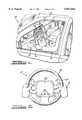
- FIG. 1is a perspective view of a remote control assembly, according to the present invention, for operating audio components and is illustrated in operational relationship with an occupant compartment of a motor vehicle;
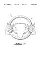
- FIG. 2is a front view of the remote control assembly of FIG. 1;
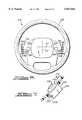
- FIG. 3is a rear view of the remote control assembly of FIG. 1;
- FIG. 4is a partial rear view of an alternative embodiment of the remote control assembly of FIG. 1;
- FIG. 5is a rear view of the remote control assembly of FIG. 1 illustrating ergonomically positive placement of hands of an operator of the motor vehicle;
- FIG. 6is a rear view of an alternative embodiment of the remote control assembly of FIG. 1;
- FIG. 7is a cross-sectional view of a rocker type switch employed in the remote control assembly of FIG. 6;
- FIG. 8is a more detailed view of the switch of the remote control assembly of FIG. 6;
- FIG. 9is a partial side view of the spoke and switch of the remote control assembly of FIG. 6.
- a remote control assemblyfor operating audio components 24 is illustrated in operational relationship with an occupant compartment 11 of a motor vehicle 12.
- a vehicle driver 14 having hands 16are seated in a driver's seat (not shown) of the motor vehicle 12.
- the driver 14has his/her hands 16 placed on a steering wheel 18 of the motor vehicle 12 in a typical driving position.
- the vehicle driver 14controls the direction of movement of the motor vehicle 12 via the steering wheel 18 as is known in the art.
- the remote control assembly 10includes the steering wheel 18.
- the steering wheel 18has a front side facing the driver 14 and a rear side facing a dash panel 23 to be described.
- the steering wheel 18includes a circular rim 19, a hub 20 positioned within the rim 19, and a spoke 21 connected at one end to the hub 20 and at the other end to the rim 19.
- the hub 20is rotatably mounted onto a steering column 22, which transfers the movement of the steering wheel 18 to a vehicle drive assembly (not shown).
- steering wheel 18, steering column 22 and vehicle drive assemblyare conventional and known in the art.
- the occupant compartment 11includes a dash panel 23 rearward of the steering wheel 18.
- the dash panel 23separates the occupant compartment 11 from an engine compartment (not shown) and houses instrument panel gages, such as a speedometer and fuel indicator, and components such as climate controls and audio components 24. It should be appreciated that the dash panel 23 and its gages and components are conventional and well known in the art.
- the audio components 24are typically positioned in the center of the dash pane 23, so that they are accessible by the driver 14 or a front passenger (not shown).
- the audio components 24may include, but are not limited to, a radio, a compact disc player or a cassette player.
- the remote control assembly 10also includes at least one, and preferably a plurality of controls 26 for controlling the operation of the audio components 24.
- the controls 26are preferably switches which actuate functions of the audio components 24.
- the switchesare toggle type switches. It should be appreciated that the functions may include, for example: volume; seek to search for next station in an AM or FM mode or next track in a CD mode; pre-set stations; AM/FM switching; scan to search for next station in the AM or FM mode or the next track in the CD mode; search to find next selection on a tape; mute to eliminate sound; or power (on/off).
- FIG. 2a typical position for the driver's hands 16 on the steering wheel 18 is illustrated.
- Drivers 14tend to grip the steering wheel 18 in a comfortable position, especially when driving long distances.
- a typical position for the driver 14is to grip the steering wheel 18 with his/her thumb 28 resting on the front side of the spoke 21 and the remaining fingers 29 wrapped around the rim 19 and facing the back side of the spoke 21.
- the front side of the steering wheel 18may also include vehicle controls 30 located on the front side of the hub 20 or the spoke 21.
- vehicle controls 30may include, for example, controls which operate a horn or cruise control.
- the vehicle controls 30are readily accessible to the driver 14, however, they are not ergonomically intuitive because the driver 14 may have to visually search for the vehicle controls 30 or move his/her hand 16 around to reach the vehicle controls 30.
- the remote control assembly 18includes selected controls 26 placed on the back side of the steering wheel 18 which provide an ergonomic advantage.
- the selected controls 26are a three part rocker switch 42 for a seek function located on a right side spoke 21 of the steering wheel 18.
- Momentarily depressing a center portion 44 of the rocker switch 42steps up through preset radio stations; depressing an upper portion 46 of the rocker switch 42 steps up to the next radio station or track; and depressing a lower portion 48 of the rocker switch 42 steps down to the next radio station or track.
- the remote control assembly 18may include a two part toggle switch 50 for volume control located on a left side spoke 21 of the steering wheel 18. Momentarily depressing an upper half 52 of the toggle switch 50 increases the volume of the audio component 24 that is playing, while momentarily depressing a lower half 54 of the toggle switch 50 decreases the volume of the audio component 24. It should be appreciated that the number and type of control switch is dependent on the function(s) of the audio component 24 to be controlled.
- the remote control assembly 110includes a control 126 for the seek function of the audio component 24.
- the control 126is a preset seek switch 156 as a separate button switch located on the right side spoke 121 of the steering wheel 118 adjacent to a two part rocker switch 158 for seeking up or down of the audio component 24. Pushing the preset seek switch 156 steps up to the next preset radio station, and pressing an upper half 160 of the rocker switch 158 steps up to the next radio station, while pressing a lower half 162 of the rocker switch 158 steps down to the next radio station.
- the back side of the steering wheel 18is shown with the placement of the fingers 29 of the driver's hands 16 on the controls 26 to illustrate the ergonomic advantage of the remote control assembly 10.
- the controls 26should be positioned on the back side of the spoke 21 so that they are easily found and operated by a finger 29 of the driver's hand 16.
- the location of the controls 26 on the back side of the steering wheel 18is ergonomically advantageous because the driver's hand 16 naturally rests on the steering wheel 18 with his/her fingers 29 on the back side of the steering wheel 18. Therefore, the driver 14 may blindly operate the switches 42, 50 with removing his/her hands 16 from the steering wheel 18 or taking his/her eyes off the vehicle driving surface.
- the remote control assembly 210includes selected controls 226 placed on the backside of the steering wheel 218 which provide an ergonomic advantage.
- the selected controls 226are a three part rocker switch 242 for a seek function located on a right side spoke 221 of the steering wheel 218.
- Momentarily depressing a center portion 244 of the rocker switch 242steps up through preset radio stations. Depressing an upper portion 246 of the rocker switch 242 steps up to the next radio station or track. Depressing a lower portion 248 of the rocker switch 242 steps down to the next radio station or track.
- the remote control assembly 210may include a second three part rocker switch 250 for volume control located on a left side spoke 221 of steering wheel 218.
- a center portion 251 of the rocker switch 250switches between AM and FM mode. Depressing the upper half 252 the rocker switch 250 increases the volume of the audio component 24 that is playing, while momentarily depressing a lower half 254 of the rocker switch 250 decreases the volume of the audio component 24. It should be appreciated that the number and type of control switch is dependent on the function(s) of the audio component 24 to be controlled.
- the controls 226are symmetrically arranged with respect to the center line C1 and C2 of the steering wheel 218 to provide an ergonomic advantage. Furthermore, the selected controls 226 have been placed in close proximity to the center line C1 to provide an ergonomic advantage because the driver's hands naturally rest on the steering wheel 218 with his/her fingers at or near the location of the controls 226. This enables the driver to easily find and operate the controls 226 blindly.
- FIG. 7a cross-sectional view of a control 226 is shown mounted in the spoke 221.
- the control 226includes a flange 264 disposed between the switch portion 266 and the base portion 268. As shown is FIG. 8, the flange portion 264 extends substantially about the perimeter of the switch portion 266. The flange portion 264 projects outwardly from the perimeter 270 of the base portion 268 such that it overlies a rim 272 formed about an aperture 274 formed in the spoke 221.
- the overlap designimproves the mountability of the controls 226 into the spoke 221. Furthermore, the overlap design provides an improved tactile response or switch reaction surface for the driver.
- the control 226includes a secondary anti-rattle arm 276 extending laterally therefrom.
- the anti-rattle arm 276includes a U-shaped receptacle 278 adapted to cooperate with a screw 280 which is used to mount the back shroud 282 to the infrastructure of the spoke 221.
- the anti-rattle arm 276enables the control 226 to be snapped into place through the aperture 274 and onto the spoke 221.
- the side of the spoke 221is shown with the placement of the control 226 relative to a reference line 284 which is roughly parallel to the tangent plane of the front side of the steering wheel 218.
- the angle A of the spoke 221is ergonomically advantageous because a driver's hand naturally rests on the steering wheel 218 with his/her fingers extending at an angle behind the back side of the steering wheel 218. Therefore, the driver may blindly operate the control 226 without having to overly extend his/her fingers or contort them in any unusual fashion.
- the specific angle Amay vary, it is presently preferred to form the angle A between 30 and 60 degrees relative to reference line 284 and most preferably to make the angle A approximately equal to 40 degrees.
- the reference line Ais selected to be substantially parallel to a tangent to the front side of the steering wheel or essentially parallel to the tangent of a driver's chest when operating the motor vehicle.
Landscapes
- Engineering & Computer Science (AREA)
- Mechanical Engineering (AREA)
- Automation & Control Theory (AREA)
- Steering Controls (AREA)
Abstract
Description
Claims (12)
Priority Applications (1)
| Application Number | Priority Date | Filing Date | Title |
|---|---|---|---|
| US08/946,821US5847664A (en) | 1995-04-17 | 1997-10-08 | Remote control assembly for operating audio components in motor vehicles |
Applications Claiming Priority (3)
| Application Number | Priority Date | Filing Date | Title |
|---|---|---|---|
| US42246495A | 1995-04-17 | 1995-04-17 | |
| US08/758,629US5721541A (en) | 1995-04-17 | 1996-11-27 | Remote control assembly for operating audio components in motor vehicle |
| US08/946,821US5847664A (en) | 1995-04-17 | 1997-10-08 | Remote control assembly for operating audio components in motor vehicles |
Related Parent Applications (1)
| Application Number | Title | Priority Date | Filing Date |
|---|---|---|---|
| US08/758,629Continuation-In-PartUS5721541A (en) | 1995-04-17 | 1996-11-27 | Remote control assembly for operating audio components in motor vehicle |
Publications (1)
| Publication Number | Publication Date |
|---|---|
| US5847664Atrue US5847664A (en) | 1998-12-08 |
Family
ID=27025609
Family Applications (1)
| Application Number | Title | Priority Date | Filing Date |
|---|---|---|---|
| US08/946,821Expired - LifetimeUS5847664A (en) | 1995-04-17 | 1997-10-08 | Remote control assembly for operating audio components in motor vehicles |
Country Status (1)
| Country | Link |
|---|---|
| US (1) | US5847664A (en) |
Cited By (11)
| Publication number | Priority date | Publication date | Assignee | Title |
|---|---|---|---|---|
| GB2359965A (en)* | 2000-02-04 | 2001-09-05 | Bosch Gmbh Robert | Operating devices in a vehicle remotely via apparatus connected to the steering wheel where the operating elements move in two and/or three dimensions |
| USD474753S1 (en) | 2002-01-22 | 2003-05-20 | Mobilearia | Communication control device |
| FR2867724A1 (en)* | 2004-03-16 | 2005-09-23 | Renault Sas | DEVICE FOR CONTROLLING THE WHEEL OR THE WHEEL FOR A MOTOR VEHICLE, OF THE TYPE COMPRISING A TOUCH PAD |
| US7038586B2 (en)* | 1999-04-29 | 2006-05-02 | Wechsler Lawrence I | Vehicle horn actuation mechanism and method |
| DE102005003565A1 (en)* | 2005-01-25 | 2006-07-27 | Andreas Peiker | Communication device e.g. mobile telephone, handling arrangement for vehicle, has Bluetooth (RTM) module integrated into fastening device, and communicating with another module that stays in connection with controlling and operating units |
| US20060284839A1 (en)* | 1999-12-15 | 2006-12-21 | Automotive Technologies International, Inc. | Vehicular Steering Wheel with Input Device |
| US20070197187A1 (en)* | 2004-03-31 | 2007-08-23 | Netec Technology Co., Ltd. | On-vehicle audiovideo systems |
| EP1232909A3 (en)* | 2001-02-19 | 2009-08-19 | Delphi Technologies, Inc. | Method and apparatus for accessing vehicle systems |
| US20110030502A1 (en)* | 2009-08-06 | 2011-02-10 | Lathrop William Brian | Motor vehicle |
| CN102664026A (en)* | 2010-12-16 | 2012-09-12 | 哈曼国际工业有限公司 | Handlebar audio controls |
| US20150158519A1 (en)* | 2013-12-09 | 2015-06-11 | Hyundai Motor Company | Apparatus for controlling sound volume for vehicle |
Citations (1)
| Publication number | Priority date | Publication date | Assignee | Title |
|---|---|---|---|---|
| US5721541A (en)* | 1995-04-17 | 1998-02-24 | Chrysler Corporation | Remote control assembly for operating audio components in motor vehicle |
- 1997
- 1997-10-08USUS08/946,821patent/US5847664A/ennot_activeExpired - Lifetime
Patent Citations (1)
| Publication number | Priority date | Publication date | Assignee | Title |
|---|---|---|---|---|
| US5721541A (en)* | 1995-04-17 | 1998-02-24 | Chrysler Corporation | Remote control assembly for operating audio components in motor vehicle |
Cited By (18)
| Publication number | Priority date | Publication date | Assignee | Title |
|---|---|---|---|---|
| US7038586B2 (en)* | 1999-04-29 | 2006-05-02 | Wechsler Lawrence I | Vehicle horn actuation mechanism and method |
| US20060284839A1 (en)* | 1999-12-15 | 2006-12-21 | Automotive Technologies International, Inc. | Vehicular Steering Wheel with Input Device |
| GB2359965A (en)* | 2000-02-04 | 2001-09-05 | Bosch Gmbh Robert | Operating devices in a vehicle remotely via apparatus connected to the steering wheel where the operating elements move in two and/or three dimensions |
| GB2359965B (en)* | 2000-02-04 | 2002-09-18 | Bosch Gmbh Robert | Apparatus for the manual operation of devices in a vehicle |
| EP1232909A3 (en)* | 2001-02-19 | 2009-08-19 | Delphi Technologies, Inc. | Method and apparatus for accessing vehicle systems |
| USD474753S1 (en) | 2002-01-22 | 2003-05-20 | Mobilearia | Communication control device |
| FR2867724A1 (en)* | 2004-03-16 | 2005-09-23 | Renault Sas | DEVICE FOR CONTROLLING THE WHEEL OR THE WHEEL FOR A MOTOR VEHICLE, OF THE TYPE COMPRISING A TOUCH PAD |
| EP1734533A4 (en)* | 2004-03-31 | 2008-04-30 | Netac Technology Co Ltd | On-vehicle audio/video system |
| US20070197187A1 (en)* | 2004-03-31 | 2007-08-23 | Netec Technology Co., Ltd. | On-vehicle audiovideo systems |
| US7689198B2 (en) | 2004-03-31 | 2010-03-30 | Netac Technology Co., Ltd. | On-vehicle audio/video systems |
| DE102005003565A1 (en)* | 2005-01-25 | 2006-07-27 | Andreas Peiker | Communication device e.g. mobile telephone, handling arrangement for vehicle, has Bluetooth (RTM) module integrated into fastening device, and communicating with another module that stays in connection with controlling and operating units |
| US20110030502A1 (en)* | 2009-08-06 | 2011-02-10 | Lathrop William Brian | Motor vehicle |
| US10118490B2 (en)* | 2009-08-06 | 2018-11-06 | Volkswagen Ag | Touch-pad integrated steering wheel for a motor vehicle |
| US10906401B2 (en) | 2009-08-06 | 2021-02-02 | Volkswagen Ag | Touch-pad integrated steering wheel for a motor vehicle |
| CN102664026A (en)* | 2010-12-16 | 2012-09-12 | 哈曼国际工业有限公司 | Handlebar audio controls |
| CN102664026B (en)* | 2010-12-16 | 2016-07-06 | 哈曼国际工业有限公司 | Handlebar audio frequency control |
| US20150158519A1 (en)* | 2013-12-09 | 2015-06-11 | Hyundai Motor Company | Apparatus for controlling sound volume for vehicle |
| US9340225B2 (en)* | 2013-12-09 | 2016-05-17 | Hyundai Motor Company | Apparatus for controlling sound volume for vehicle |
Similar Documents
| Publication | Publication Date | Title |
|---|---|---|
| US5721541A (en) | Remote control assembly for operating audio components in motor vehicle | |
| US5847664A (en) | Remote control assembly for operating audio components in motor vehicles | |
| EP1502835A1 (en) | Method and apparatus for accessing vehicle systems | |
| EP1995752B1 (en) | Multifunctional rotary switch | |
| US4731769A (en) | Central servicing and information controller for vehicle auxiliary equipment | |
| EP1343113B1 (en) | Input apparatus for vehicle-installed instruments | |
| US7680574B2 (en) | Vehicle information system with steering wheel controller | |
| US20100188343A1 (en) | Vehicular control system comprising touch pad and vehicles and methods | |
| US20090174682A1 (en) | Instrumentation Module For A Vehicle | |
| JP3335146B2 (en) | Steering wheel | |
| JP2001350561A (en) | Function controller equipped with at least one selector | |
| US20060175183A1 (en) | Vehicle switch assembly | |
| JP2000306469A (en) | Steering device | |
| US20020047255A1 (en) | Steering assembly with a fixed central pad, corresponding central pad and corresponding motor vehicle | |
| JP6201864B2 (en) | Vehicle control device | |
| JP2003072486A (en) | Operation switch device for vehicles | |
| GB2422184A (en) | Actual or virtual dial on a vehicle steering wheel for display indicator movement and selection | |
| US7516811B2 (en) | Vehicle accessory pedal and method | |
| EP1411410A1 (en) | Sense of force imparting type input device | |
| JP4393868B2 (en) | Control module provided under the steering wheel | |
| WO2001012458A1 (en) | Modular instrument panel | |
| JPH0724666U (en) | Vehicle switch device | |
| JPH0133390Y2 (en) | ||
| JPH0732241Y2 (en) | Vehicle operation switch | |
| JPH1142958A (en) | Center console switch knob arrangement structure |
Legal Events
| Date | Code | Title | Description |
|---|---|---|---|
| AS | Assignment | Owner name:CHRYSLER CORPORATION, MICHIGAN Free format text:ASSIGNMENT OF ASSIGNORS INTEREST;ASSIGNORS:ZAMPLAS, GEORGE J.;REPP, JAMES H;RAUCH, JOHN E.;REEL/FRAME:008845/0481;SIGNING DATES FROM 19970930 TO 19971008 | |
| STCF | Information on status: patent grant | Free format text:PATENTED CASE | |
| FPAY | Fee payment | Year of fee payment:4 | |
| FPAY | Fee payment | Year of fee payment:8 | |
| AS | Assignment | Owner name:WILMINGTON TRUST COMPANY, DELAWARE Free format text:GRANT OF SECURITY INTEREST IN PATENT RIGHTS - FIRST PRIORITY;ASSIGNOR:CHRYSLER LLC;REEL/FRAME:019773/0001 Effective date:20070803 Owner name:WILMINGTON TRUST COMPANY,DELAWARE Free format text:GRANT OF SECURITY INTEREST IN PATENT RIGHTS - FIRST PRIORITY;ASSIGNOR:CHRYSLER LLC;REEL/FRAME:019773/0001 Effective date:20070803 | |
| AS | Assignment | Owner name:WILMINGTON TRUST COMPANY, DELAWARE Free format text:GRANT OF SECURITY INTEREST IN PATENT RIGHTS - SECOND PRIORITY;ASSIGNOR:CHRYSLER LLC;REEL/FRAME:019767/0810 Effective date:20070803 Owner name:WILMINGTON TRUST COMPANY,DELAWARE Free format text:GRANT OF SECURITY INTEREST IN PATENT RIGHTS - SECOND PRIORITY;ASSIGNOR:CHRYSLER LLC;REEL/FRAME:019767/0810 Effective date:20070803 | |
| AS | Assignment | Owner name:DAIMLERCHRYSLER CORPORATION, MICHIGAN Free format text:CHANGE OF NAME;ASSIGNOR:CHRYSLER CORPORATION;REEL/FRAME:021826/0034 Effective date:19981116 | |
| AS | Assignment | Owner name:DAIMLERCHRYSLER COMPANY LLC, MICHIGAN Free format text:CHANGE OF NAME;ASSIGNOR:DAIMLERCHRYSLER CORPORATION;REEL/FRAME:021832/0256 Effective date:20070329 Owner name:CHRYSLER LLC, MICHIGAN Free format text:CHANGE OF NAME;ASSIGNOR:DAIMLERCHRYSLER COMPANY LLC;REEL/FRAME:021832/0233 Effective date:20070727 | |
| AS | Assignment | Owner name:US DEPARTMENT OF THE TREASURY, DISTRICT OF COLUMBI Free format text:GRANT OF SECURITY INTEREST IN PATENT RIGHTS - THIR;ASSIGNOR:CHRYSLER LLC;REEL/FRAME:022259/0188 Effective date:20090102 Owner name:US DEPARTMENT OF THE TREASURY,DISTRICT OF COLUMBIA Free format text:GRANT OF SECURITY INTEREST IN PATENT RIGHTS - THIR;ASSIGNOR:CHRYSLER LLC;REEL/FRAME:022259/0188 Effective date:20090102 | |
| AS | Assignment | Owner name:CHRYSLER LLC, MICHIGAN Free format text:RELEASE BY SECURED PARTY;ASSIGNOR:US DEPARTMENT OF THE TREASURY;REEL/FRAME:022910/0273 Effective date:20090608 | |
| AS | Assignment | Owner name:CHRYSLER LLC, MICHIGAN Free format text:RELEASE OF SECURITY INTEREST IN PATENT RIGHTS - FIRST PRIORITY;ASSIGNOR:WILMINGTON TRUST COMPANY;REEL/FRAME:022910/0498 Effective date:20090604 Owner name:CHRYSLER LLC, MICHIGAN Free format text:RELEASE OF SECURITY INTEREST IN PATENT RIGHTS - SECOND PRIORITY;ASSIGNOR:WILMINGTON TRUST COMPANY;REEL/FRAME:022910/0740 Effective date:20090604 Owner name:NEW CARCO ACQUISITION LLC, MICHIGAN Free format text:ASSIGNMENT OF ASSIGNORS INTEREST;ASSIGNOR:CHRYSLER LLC;REEL/FRAME:022915/0001 Effective date:20090610 Owner name:THE UNITED STATES DEPARTMENT OF THE TREASURY, DIST Free format text:SECURITY AGREEMENT;ASSIGNOR:NEW CARCO ACQUISITION LLC;REEL/FRAME:022915/0489 Effective date:20090610 Owner name:CHRYSLER LLC,MICHIGAN Free format text:RELEASE OF SECURITY INTEREST IN PATENT RIGHTS - FIRST PRIORITY;ASSIGNOR:WILMINGTON TRUST COMPANY;REEL/FRAME:022910/0498 Effective date:20090604 Owner name:CHRYSLER LLC,MICHIGAN Free format text:RELEASE OF SECURITY INTEREST IN PATENT RIGHTS - SECOND PRIORITY;ASSIGNOR:WILMINGTON TRUST COMPANY;REEL/FRAME:022910/0740 Effective date:20090604 Owner name:NEW CARCO ACQUISITION LLC,MICHIGAN Free format text:ASSIGNMENT OF ASSIGNORS INTEREST;ASSIGNOR:CHRYSLER LLC;REEL/FRAME:022915/0001 Effective date:20090610 Owner name:THE UNITED STATES DEPARTMENT OF THE TREASURY,DISTR Free format text:SECURITY AGREEMENT;ASSIGNOR:NEW CARCO ACQUISITION LLC;REEL/FRAME:022915/0489 Effective date:20090610 | |
| AS | Assignment | Owner name:CHRYSLER GROUP LLC, MICHIGAN Free format text:CHANGE OF NAME;ASSIGNOR:NEW CARCO ACQUISITION LLC;REEL/FRAME:022919/0126 Effective date:20090610 Owner name:CHRYSLER GROUP LLC,MICHIGAN Free format text:CHANGE OF NAME;ASSIGNOR:NEW CARCO ACQUISITION LLC;REEL/FRAME:022919/0126 Effective date:20090610 | |
| FPAY | Fee payment | Year of fee payment:12 | |
| AS | Assignment | Owner name:CHRYSLER GROUP LLC, MICHIGAN Free format text:RELEASE BY SECURED PARTY;ASSIGNOR:THE UNITED STATES DEPARTMENT OF THE TREASURY;REEL/FRAME:026343/0298 Effective date:20110524 Owner name:CHRYSLER GROUP GLOBAL ELECTRIC MOTORCARS LLC, NORT Free format text:RELEASE BY SECURED PARTY;ASSIGNOR:THE UNITED STATES DEPARTMENT OF THE TREASURY;REEL/FRAME:026343/0298 Effective date:20110524 | |
| AS | Assignment | Owner name:CITIBANK, N.A., NEW YORK Free format text:SECURITY AGREEMENT;ASSIGNOR:CHRYSLER GROUP LLC;REEL/FRAME:026404/0123 Effective date:20110524 | |
| AS | Assignment | Owner name:CITIBANK, N.A., NEW YORK Free format text:SECURITY AGREEMENT;ASSIGNOR:CHRYSLER GROUP LLC;REEL/FRAME:026435/0652 Effective date:20110524 | |
| AS | Assignment | Owner name:JPMORGAN CHASE BANK, N.A., ILLINOIS Free format text:SECURITY AGREEMENT;ASSIGNOR:CHRYSLER GROUP LLC;REEL/FRAME:032384/0640 Effective date:20140207 | |
| AS | Assignment | Owner name:FCA US LLC, MICHIGAN Free format text:CHANGE OF NAME;ASSIGNOR:CHRYSLER GROUP LLC;REEL/FRAME:035553/0356 Effective date:20141203 | |
| AS | Assignment | Owner name:FCA US LLC, FORMERLY KNOWN AS CHRYSLER GROUP LLC, Free format text:RELEASE OF SECURITY INTEREST RELEASING SECOND-LIEN SECURITY INTEREST PREVIOUSLY RECORDED AT REEL 026426 AND FRAME 0644, REEL 026435 AND FRAME 0652, AND REEL 032384 AND FRAME 0591;ASSIGNOR:CITIBANK, N.A.;REEL/FRAME:037784/0001 Effective date:20151221 | |
| AS | Assignment | Owner name:FCA US LLC (FORMERLY KNOWN AS CHRYSLER GROUP LLC), Free format text:RELEASE BY SECURED PARTY;ASSIGNOR:CITIBANK, N.A.;REEL/FRAME:042885/0255 Effective date:20170224 | |
| AS | Assignment | Owner name:FCA US LLC (FORMERLY KNOWN AS CHRYSLER GROUP LLC), Free format text:RELEASE BY SECURED PARTY;ASSIGNOR:JPMORGAN CHASE BANK, N.A.;REEL/FRAME:048177/0356 Effective date:20181113 |