US5847546A - System and apparatus for generating a continuosly variable reference signal for controlling battery cell charging - Google Patents
System and apparatus for generating a continuosly variable reference signal for controlling battery cell chargingDownload PDFInfo
- Publication number
- US5847546A US5847546AUS08/858,202US85820297AUS5847546AUS 5847546 AUS5847546 AUS 5847546AUS 85820297 AUS85820297 AUS 85820297AUS 5847546 AUS5847546 AUS 5847546A
- Authority
- US
- United States
- Prior art keywords
- battery
- battery pack
- battery cells
- voltage
- charging
- Prior art date
- Legal status (The legal status is an assumption and is not a legal conclusion. Google has not performed a legal analysis and makes no representation as to the accuracy of the status listed.)
- Expired - Lifetime
Links
- 238000005516engineering processMethods0.000abstractdescription10
- 239000003990capacitorSubstances0.000description11
- 238000010586diagramMethods0.000description9
- 230000001105regulatory effectEffects0.000description8
- 239000007787solidSubstances0.000description7
- 238000006243chemical reactionMethods0.000description6
- 230000008901benefitEffects0.000description4
- 230000010354integrationEffects0.000description4
- 238000013021overheatingMethods0.000description4
- OJIJEKBXJYRIBZ-UHFFFAOYSA-Ncadmium nickelChemical compound[Ni].[Cd]OJIJEKBXJYRIBZ-UHFFFAOYSA-N0.000description3
- 238000004891communicationMethods0.000description3
- 230000001276controlling effectEffects0.000description3
- 238000012423maintenanceMethods0.000description3
- 230000008859changeEffects0.000description2
- 239000013078crystalSubstances0.000description2
- 238000013461designMethods0.000description2
- 238000013459approachMethods0.000description1
- 230000003750conditioning effectEffects0.000description1
- 230000008878couplingEffects0.000description1
- 238000010168coupling processMethods0.000description1
- 238000005859coupling reactionMethods0.000description1
- 230000009977dual effectEffects0.000description1
- 229910052987metal hydrideInorganic materials0.000description1
- 238000000034methodMethods0.000description1
- 238000012986modificationMethods0.000description1
- 230000004048modificationEffects0.000description1
- 238000012544monitoring processMethods0.000description1
- 230000008569processEffects0.000description1
- 238000012545processingMethods0.000description1
- 239000004065semiconductorSubstances0.000description1
Images


Classifications
- H—ELECTRICITY
- H02—GENERATION; CONVERSION OR DISTRIBUTION OF ELECTRIC POWER
- H02J—CIRCUIT ARRANGEMENTS OR SYSTEMS FOR SUPPLYING OR DISTRIBUTING ELECTRIC POWER; SYSTEMS FOR STORING ELECTRIC ENERGY
- H02J7/00—Circuit arrangements for charging or depolarising batteries or for supplying loads from batteries
- H02J7/0068—Battery or charger load switching, e.g. concurrent charging and load supply
- G—PHYSICS
- G01—MEASURING; TESTING
- G01R—MEASURING ELECTRIC VARIABLES; MEASURING MAGNETIC VARIABLES
- G01R31/00—Arrangements for testing electric properties; Arrangements for locating electric faults; Arrangements for electrical testing characterised by what is being tested not provided for elsewhere
- G01R31/36—Arrangements for testing, measuring or monitoring the electrical condition of accumulators or electric batteries, e.g. capacity or state of charge [SoC]
- G01R31/3644—Constructional arrangements
- G01R31/3648—Constructional arrangements comprising digital calculation means, e.g. for performing an algorithm
- G—PHYSICS
- G01—MEASURING; TESTING
- G01R—MEASURING ELECTRIC VARIABLES; MEASURING MAGNETIC VARIABLES
- G01R31/00—Arrangements for testing electric properties; Arrangements for locating electric faults; Arrangements for electrical testing characterised by what is being tested not provided for elsewhere
- G01R31/36—Arrangements for testing, measuring or monitoring the electrical condition of accumulators or electric batteries, e.g. capacity or state of charge [SoC]
- G01R31/382—Arrangements for monitoring battery or accumulator variables, e.g. SoC
- G01R31/3842—Arrangements for monitoring battery or accumulator variables, e.g. SoC combining voltage and current measurements
- H—ELECTRICITY
- H01—ELECTRIC ELEMENTS
- H01M—PROCESSES OR MEANS, e.g. BATTERIES, FOR THE DIRECT CONVERSION OF CHEMICAL ENERGY INTO ELECTRICAL ENERGY
- H01M10/00—Secondary cells; Manufacture thereof
- H01M10/42—Methods or arrangements for servicing or maintenance of secondary cells or secondary half-cells
- H01M10/425—Structural combination with electronic components, e.g. electronic circuits integrated to the outside of the casing
- H01M10/4257—Smart batteries, e.g. electronic circuits inside the housing of the cells or batteries
- H—ELECTRICITY
- H01—ELECTRIC ELEMENTS
- H01M—PROCESSES OR MEANS, e.g. BATTERIES, FOR THE DIRECT CONVERSION OF CHEMICAL ENERGY INTO ELECTRICAL ENERGY
- H01M10/00—Secondary cells; Manufacture thereof
- H01M10/42—Methods or arrangements for servicing or maintenance of secondary cells or secondary half-cells
- H01M10/48—Accumulators combined with arrangements for measuring, testing or indicating the condition of cells, e.g. the level or density of the electrolyte
- H—ELECTRICITY
- H02—GENERATION; CONVERSION OR DISTRIBUTION OF ELECTRIC POWER
- H02J—CIRCUIT ARRANGEMENTS OR SYSTEMS FOR SUPPLYING OR DISTRIBUTING ELECTRIC POWER; SYSTEMS FOR STORING ELECTRIC ENERGY
- H02J7/00—Circuit arrangements for charging or depolarising batteries or for supplying loads from batteries
- H02J7/00032—Circuit arrangements for charging or depolarising batteries or for supplying loads from batteries characterised by data exchange
- H02J7/00036—Charger exchanging data with battery
- H—ELECTRICITY
- H02—GENERATION; CONVERSION OR DISTRIBUTION OF ELECTRIC POWER
- H02J—CIRCUIT ARRANGEMENTS OR SYSTEMS FOR SUPPLYING OR DISTRIBUTING ELECTRIC POWER; SYSTEMS FOR STORING ELECTRIC ENERGY
- H02J7/00—Circuit arrangements for charging or depolarising batteries or for supplying loads from batteries
- H02J7/00047—Circuit arrangements for charging or depolarising batteries or for supplying loads from batteries with provisions for charging different types of batteries
- G—PHYSICS
- G01—MEASURING; TESTING
- G01R—MEASURING ELECTRIC VARIABLES; MEASURING MAGNETIC VARIABLES
- G01R31/00—Arrangements for testing electric properties; Arrangements for locating electric faults; Arrangements for electrical testing characterised by what is being tested not provided for elsewhere
- G01R31/36—Arrangements for testing, measuring or monitoring the electrical condition of accumulators or electric batteries, e.g. capacity or state of charge [SoC]
- G01R31/374—Arrangements for testing, measuring or monitoring the electrical condition of accumulators or electric batteries, e.g. capacity or state of charge [SoC] with means for correcting the measurement for temperature or ageing
- Y—GENERAL TAGGING OF NEW TECHNOLOGICAL DEVELOPMENTS; GENERAL TAGGING OF CROSS-SECTIONAL TECHNOLOGIES SPANNING OVER SEVERAL SECTIONS OF THE IPC; TECHNICAL SUBJECTS COVERED BY FORMER USPC CROSS-REFERENCE ART COLLECTIONS [XRACs] AND DIGESTS
- Y02—TECHNOLOGIES OR APPLICATIONS FOR MITIGATION OR ADAPTATION AGAINST CLIMATE CHANGE
- Y02E—REDUCTION OF GREENHOUSE GAS [GHG] EMISSIONS, RELATED TO ENERGY GENERATION, TRANSMISSION OR DISTRIBUTION
- Y02E60/00—Enabling technologies; Technologies with a potential or indirect contribution to GHG emissions mitigation
- Y02E60/10—Energy storage using batteries
- Y—GENERAL TAGGING OF NEW TECHNOLOGICAL DEVELOPMENTS; GENERAL TAGGING OF CROSS-SECTIONAL TECHNOLOGIES SPANNING OVER SEVERAL SECTIONS OF THE IPC; TECHNICAL SUBJECTS COVERED BY FORMER USPC CROSS-REFERENCE ART COLLECTIONS [XRACs] AND DIGESTS
- Y10—TECHNICAL SUBJECTS COVERED BY FORMER USPC
- Y10S—TECHNICAL SUBJECTS COVERED BY FORMER USPC CROSS-REFERENCE ART COLLECTIONS [XRACs] AND DIGESTS
- Y10S320/00—Electricity: battery or capacitor charging or discharging
- Y10S320/10—Nonbattery load controls charging
Definitions
- the present inventionrelates to a computer power supply system and, more particularly, to a computer power supply system which includes a smart battery pack and a variable output battery charger system which enables optimal charging of the battery pack during all operating conditions while allowing the power supply to be utilized with battery packs having different charging characteristics.
- Power supply systemsare generally known in the art. Such systems are utilized in a variety of applications to provide electrical power to portable devices, such as portable personal computers. Such power supply systems normally include a battery pack and a battery charger system. The battery charger systems are used to charge the battery packs and to enable a computer or other portable device to be operated from a source of AC electrical power. The battery pack normally provides several hours of portable operation before requiring recharging.
- batteriesMore particularly, nickel cadmium (Nicd) and nickel-metal hydride (NiMH) batteries have been known to be used in applications for portable personal computers. Such batteries generally provide a few hours of operation before requiring recharging.
- the charging characteristics of such batteriesenable such batteries to be recharged by relatively simple battery chargers hating two fixed modes of operation: a trickle charge mode and a fast charge mode.
- the trickle charge modethe battery charger provides a relatively low level constant current (e.g., 100 milliamperes) to the battery over a relatively long time, for example ten to twelve hours.
- a relatively higher current levele.g., 2 amperes
- the charge level of the batteriesis continuously sensed.
- the battery chargingis terminated in order to prevent overheating and damage of the batteries.
- a system control processoris used to measure the charge level of the battery as well as the operational status (e.g., on-off) of the computer.
- signals representative of the battery voltage and temperature as well as the on-off status of the computer systemare applied to the SCP which, in turn, provides a logic level signal to control the battery charger.
- the SCPenables either a fast charge for a relatively short time or a trickle charge for a relatively longer time in order to charge the battery.
- the battery charger and battery packhave known to be provided as independent modules, disposed in separate enclosures relative to the computer system.
- either one or both of the modulesare adapted to be connected to the computer system at one time.
- Thisenables the computer system to be operated from either the battery pack or the battery charger.
- Such an applicationalso allows the battery pack and battery charger module to be connected to the computer system at the same time, thus enabling batteries to be charged while the battery charger is operating the computer system.
- the systemalso enables the battery charger to be used to charge the battery pack separately from the computer system.
- a dedicated microprocessoris used in the alternate embodiment to monitor the charge level of the battery and the operating status of the computer system in order to control a two-level battery charging system as discussed above.
- the dedicated microprocessoris located in the housing with the battery charger.
- any change in the battery technology to one having different charging characteristics or changes in the battery capacitystill requires a design change of the battery charger, thus making such changes of battery technology or capacity relatively costly to a computer manufacturer.
- a dedicated microprocessoris disposed in the battery pack to enable the battery pack to be more of a stand-alone subsystem.
- Such a systemprovides the ability to upgrade to a different type of battery pack having similar charge/discharge characteristics.
- the above mentioned system as well as the other systems discussed aboveutilize battery chargers that provide fixed level current charging to the battery pack. More particularly, whether controlled from the SCP or from a dedicated processor, the battery chargers discussed above are known to operate in two fixed current modes; namely, a fast charge mode and a trickle charge mode. Although such charging characteristics are suitable for nickel cadmium batteries and other types of batteries, such charging characteristics may not be suitable for new battery technologies which have recently become available that provide for higher energy density. Such new battery technologies may require different charging characteristics which could not be provided by the known battery charging systems discussed above. For example, new battery technologies may be less tolerant of continuous overcharge in order to maintain the battery at full capacity in contradistinction to nickel cadmium batteries. In addition, the fixed two-level charge characteristics of known battery chargers may not be suitable because of the capacity rating (the fast charge current may be too high or too low). With such new battery technologies, the battery charging circuit has to be redesigned for each different battery technology used.
- Another problem with such known power supply systemsis the inability of such systems to efficiently utilize the capacity of the battery charger. This inability is based on the failure of such known systems to detect the current load demand placed on the AC power supply battery charger by the computer system. In such systems, a worst-case design approach is known to be used which inhibits fast charging of the battery pack while the computer system is operational in order to avoid exceeding the capacity of the battery charger. In particular, in order to keep the cost and the weight of the system down, the battery charger capacity is known to be sized based on an estimate of the maximum load demand of the computer system. However, it is known that during the majority of time, the computer system is not operating at maximum load.
- FIG. 1is a block diagram of a power supply system in accordance with the present invention
- FIG. 2is a block diagram of a smart battery pack in accordance with the present invention.
- FIG. 3is a block diagram of a battery charging system in accordance with the present invention.
- FIG. 4is a graphical representation of the charging current supplied by the battery charger in accordance with the present invention as a function of the duty cycle of the control signal from the battery pack;
- FIGS. 5A and 5Brepresent exemplary schematic diagrams of the smart battery pack illustrated in FIG. 2;
- FIG. 6Ais an exemplary schematic diagram of a circuit adapted to regulate the charging current as a function of the load demand of the computer system
- FIG. 6Bis an exemplary schematic diagram of the battery charging system illustrated in FIG. 3.
- FIGS. 7-19are flow diagrams for the power supply system in accordance with the present invention.
- the power supply system in accordance with the present inventionprovides several advantages over known power supply systems thus making it suitable for portable personal computers.
- the power supply system in accordance with the present inventionimproves the. interchangeability of system components. More specifically, the system allows a standard or generic battery charger system to be utilized with various battery technologies having different capacities and/or different charging characteristics. Another benefit of the invention is that it enables more effective use of the capacity of the battery charger. More particularly, the system in accordance with the present invention takes advantage of the full capacity of the power supply by monitoring the load placed on the system by the computer system. By sensing the load placed on the charger by the computer system, the battery pack can be optimally charged under all conditions.
- a known portable personal computermight require 6 watts to operate while the battery pack might require 14 watts for fast charge and 1 watt for a trickle charge.
- the battery charger systemin such an application can simultaneously fast charge the batteries and operate the computer system.
- the computer systemUnder worst case loading conditions, the computer system might draw up to 16 watts of power, leaving 4 watts for charging the battery pack even though the computer system is operating at maximum load.
- the residual capacity of the battery charger systemcan be utilized to charge the battery pack 22 during such a worst case loading system at other than a trickle charge (e.g., 1 watt) as in known systems.
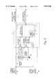
- the power supply system in accordance with the present inventionincludes a smart battery pack, shown within the dashed box 22, and a battery charger 24.
- the smart battery pack 22 and battery charger 24form the power supply system 20 for use with a portable electrical load, such as a portable personal computer 26, to enable two modes of operation: a battery mode and an AC mode.
- a battery modethe computer system 26 is powered by the battery along line 27.
- an AC modea source of regulated DC voltage is supplied by the battery charger 24 to the computer system 26 along line 28 to enable the computer system 26 to be powered from the battery charger 24 while at the same time charging the battery pack 22.
- the level of charging current applied to the battery pack 22 over line 30is controlled by a battery control circuit 34 along line 29.
- a source of controlled charge currentis supplied to the battery pack 22 along line 30 which enables the battery pack 22 to be optimally charged during all operating conditions of the computer system 26.
- a bi-directional data link 33is utilized to provide communication between the battery pack 22 and the computer system 26. For example, as will be discussed in more detail below, the battery pack 22 initiates an INHIBIT signal to the computer system 26 when the battery level is relatively low to inhibit operation of the computer system 26 in order to avoid damage to the battery pack 22. Additionally, the serial data link 33 may be used to provide the current battery charge status to the computer system 26.
- the smart battery pack 22includes a plurality of battery cells 32 for providing a portable electrical power supply and an internal battery control circuit 34, as well as circuitry for sensing the load demand of the computer system 26 as well as the temperature and voltage of the battery cells 32.
- a temperature sensor 44such as a thermistor, is applied to the battery control circuit 34 along lines 45 and 46.
- the temperature sensor 44is used to sense the temperature of the battery pack 22 in order to avoid overheating and damage.
- the load and charging current to and from the battery cells 32is sensed by a current sensing resistor 48, serially connected between a negative terminal of the battery cells 32 and system ground 50.
- the voltage across the current sensing resistor 48is applied to the battery control circuit 34 along lines 51 and 52.
- the battery voltagewhich represents the charge level of the battery cells 32, is sensed by connecting the positive and negative terminals of the battery cell 32 to the battery control circuit 34 along lines 51 and 53.
- the battery control circuit 34regulates the amount of charging current applied to the battery 32 over line 30.
- the battery control circuit 34In order to regulate the charging current from the battery charger 24, the battery control circuit 34 in accordance with the present invention outputs a fixed frequency, variable duty cycle pulse train. More particularly, the battery control circuit 34 includes a PWM control circuit 60 that is adapted to provide a pulse width modulated (PWM) control signal along line 29 to the battery charger 24. The duty cycle of the PWM signal is used to modulate the charging current from the battery charger 24 along line 30. As better shown in FIG. 2, the PWM circuit 60 is provided within a microcontroller 62, having an onboard PWM circuit 60, such as a Signetics Model 87C752. For simplicity, the battery control circuit 34, shown in FIG. 2 also illustrates a plurality of control circuits 68,. 70 and 72, as will be discussed in more detail below, (represented as operational amplifiers in FIG. 2 for simplicity) for conditioning the signals from the temperature sensor 44, current sensor 48 and the voltage across the battery cells 32, respectively.
- PWMpulse width modulated
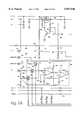
- the battery charger system 24, shown in FIG. 3,includes a switching mode current regulator 74.and a feedback circuit, shown within the dashed box 76.
- the feedback circuit 76includes a pair of operational amplifiers 78 and 80 and a summing junction 84.
- a current sensing resistor 85provides the feedback circuit 76 with an indication of the present charging current applied to the smart battery pack 22 along line 30. In particular, the voltage across the current sensing resistor 85 is applied to the operational amplifier 78.
- the output of the operational amplifier 78is applied to a positive input of the summing junction 84.
- the PWM signal along line 29 from the battery control circuit 34is applied to a low pass filter 82, which includes a resistor 87 and a capacitor 86.
- the low pass filter 82is used to provide the DC value of the signal on line 29 that is proportional to the duty cycle of the PWM signal.
- the output of the low pass filter 82is applied to the operational amplifier 80 whose output is applied to a negative input of the summing junction 84.
- the output of the summing junction 84thus represents a feedback voltage which, in turn, is used to control the charging current from the switch mode current regulator 74 according to the charge load of the battery cells 32 and the residual capacity of the charger system 24.
- the PWM signal from the smart battery pack 22provides several advantages. First, it provides a variable feedback signal to enable the output current from the regulator 74 to be regulated between its minimum and maximum limits. Second, a PWM-type signal obviates the need for an analog-to-digital converter. Third, low cost microcontrollers, such as the microcontroller 62, generally include a PWM output signal. Accordingly, the use of a PWM signal for regulating the charger system 24 allows the charging current along line 30 to be regulated without adding cost or hardware to the overall system.
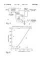
- FIG. 4represents an graphical illustration of the PWM signal duty cycle as a function of charge current in milliamperes of an exemplary system.
- the horizontal axis 88is representative of the duty cycle of the PWM control signal
- the vertical axis 90is representative of the charging current provided by the battery charger 24 along line 30 in milliamperes.
- the minimum and maximum limits of the charging currentare illustrated by the points 92 and 94, respectively, in FIG. 4.
- the systemcan provide a variable charging current, as indicated by the curve 96, that is continuously variable throughout a relatively wide range of duty cycles from a threshold duty cycle as indicated by the point 98 on the horizontal axis 88 to 100% duty cycle.
- the system in accordance with the present inventionis adapted to provide a variable charging current to the smart battery pack 22 in order to provide optimal charging of the battery pack 22 during all operating conditions of the computer system 26.
- FIGS. 5A and 5BAn exemplary schematic diagram of the smart battery pack 22 is illustrated in FIGS. 5A and 5B.
- the battery cells 32are adapted to be connected across the terminals 100 and 102, while the temperature sensor 44 is connected across the terminals 104 and 106.
- the line 30 from the battery charger system 24 (FIG. 1)is also connected to the terminal 100.
- the charging current to and load current from the battery cells 32is sensed by the current sensing resistor 48, serially connected between a negative terminal BT- of the battery cell 32 and system ground by way of a current limiting resistor 107.
- the voltage drop across the current sensing resistor 48is applied to the microcontroller 62 by way of an analog-to-digital converter (ADC).
- ADCanalog-to-digital converter
- the ADCis formed as a dual-slope ADC and includes the circuitry shown within the dashed box 108.
- the circuitry within the dashed box 108includes an integrator, generally identified with the reference numeral 110, a comparator 112 and three solid state switches 114, 116 and 118.
- the ADCfunctions by integrating the unknown voltage across the current sensing resistor 48 for a fixed time period and then integrating a known voltage of opposite polarity until the integrator 110 is reset.
- the amount of time required to reset the integrator 110is proportional to the voltage across the current sensing resistor 48.
- the integration timeproportional to the voltage drop across current sensing resistor 48 and, in turn, the current flowing therethrough.
- the solid state switches 114, 116 and 118enable the current sensing resistor 48 as well as a reference voltage to be connected and disconnected from the integrator 110. These solid state switches 114, 116 and 118 are under the control of the microcontroller 62.
- the solid state switch 114is used to connect a reference voltage to the integrator 110 by way of the input resistors 120 and 122.
- the solid state switch 116is adapted to connect one side of the current sensing resistor 48 to an inverting input of the integrator 110 by way of the input resistor 122 and an input resistor 124.
- the other side of the current sensing resistor 48is connected to a non-inverting input of the integrator 110 by way of another resistor 126.
- the integrator 110 discharge pathis controlled by way of the solid state switch 118 which connects the inverting input of the integrator 110 to system ground 50 by way of the resistors 107 and 122 as well as a resistor 128.
- the non-inverting input of the integrator 110is offset by a predetermined value, for example 100 mv.
- the value of the offset voltageis selected to be greater than the largest voltage drop across the current sensing resistor 48. As such, all input voltages will be negative with respect to the non-inverting input of integrator 110 to ensure that the integrator 110 output will always be positive.
- the offset voltage, applied to the non-inverting input of the integrator 110,is developed by way of a voltage divider network that includes resistors 134 and 136 as well as the resistor 126, connected to a reference voltage, such as VCC.
- a bypass capacitor 138is also connected to the non-inverting input of the integrator 110 in parallel with the resistor 126.
- the output of the integrator 110is applied to the comparator circuit 112 which includes the comparator 127, a feedback resistor 126 and an input resistor 128.
- the feedback resistor 126 in the comparator circuit 112adds a small amount of hysteresis to enable faster switching of the comparator 127.
- the output of the integrator 110is applied to a non-inverting input of the comparator 127 by way of the input resistor 128.
- a reference voltageis applied to the inverting input of the comparator 127.
- resistors 126 and 136provide a reference value, for example 220 mv, to compensate for the off-set that prevents the integrator 110 from integrating to zero.
- a bypass capacitor 137is used to couple the inverting input of the comparator 127 to system ground 50.
- the ADC 108is initialized by connecting the inverting terminal of the integrator 110 to system ground 50 for a predetermined time period, for example 2 seconds, and then opened by way of the switch 118, in order to cause the output of the integrator 110 to rise. Subsequently, the switch 114 is closed and connects a reference voltage to the integrator 110 by way of the resistor 120 and 122. This causes the output of the integrator 110 to ramp down to a zero crossing reference voltage which, in turn, causes the comparator circuit 112 output to switch. The time period between closing of the switch 114 and the switching of the comparator circuit 112 is measured by the microcontroller 62. This time period corresponds to a zero volt input and is used to compensate for the offset in the integrator 110.
- a predetermined time periodfor example 2 seconds
- the zero volt input time determinationis performed initially and occasionally afterward to compensate for offset voltage drift of the integrator 110.
- the switch 116is closed for a predetermined time period, for example 2 seconds, and then opened in order to cause the integrator output voltage to ramp up.
- the switch 114is then closed again to cause the reference voltage to be connected to the integrator 110.
- the switch 114is closed until the integrator output voltage ramps down to the zero crossing reference voltage, which causes the comparator circuit 112 to switch.
- the time period between the closing of the switch 114 and the switching of the comparator circuit 112corresponds to the voltage across the current sensing resistor 48 plus the zero offset.
- This time periodis subtracted from the zero volt input time determined above to provide a signal directly proportional to the voltage across the current sensing resistor 48.
- a negative resultindicates that the voltage across the current sensing resistor was negative while a positive result indicates that the voltage across the current sensing resistor 48 was positive.
- the ADC 108utilizes the timing function of the microcontroller 62.
- the comparator circuit 112 outputis connected to an interrupt port on the microcontroller 62.
- the microcontroller 62is further utilized to control the solid state switches 114, 116 and 118 in the manner discussed above.
- the control terminals of the switches 114, 116 and 118are connected to I/O ports of the microcontroller which provide logic level signals to the control terminals to cause the switches 114, 116 and 118 to open and close in the sequence discussed above.
- the battery voltageis also sensed and used to control the charging current provided by the battery charger 24.
- the positive battery terminal BT+is applied to on-board ADC port on the microcontroller 62 by way of a voltage divider circuit 150, which includes serially coupled resistors 152 and 154.
- the system statusis sensed and applied to another ADC port on the microcontroller 62.
- the system status 8-10Vis applied to the microcontroller 62 by way of another voltage divider network 151 which includes the resistors 153 and 155.
- the system status line 8-10Vis available from the computer system 26 and indicates by way of its voltage level, the status of the system.
- the system status lineoutputs four different voltage levels on line 8-10V, 10V, 8V, 5V, 0V as a function of the status.
- the 10V signalis used to represent the battery charger system 24 is connected to the computer system 26 and the computer system 26 is off which represents a condition whereby the battery cells 32 can be charged utilizing the full capacity of the charger system 24.
- the 8V signalis used to represent that the battery charger system 24 is connected and the computer system 26 is on.
- the 5V signalis used to indicate that the computer system 26 is on and being powered by the battery pack 22.
- the 0V signalis used to represent various status, such as no battery charger 24 and no computer 26 connected to the battery pack 22. These signals are used to control the charging current applied to the battery pack 22.
- the battery voltageis monitored.
- an INHIBIT signalis initiated to shut down the computer system 26.
- the INHIBIT signalis available at an output port of the microcontroller 62 and applied to the computer system 26 by way of a resistor 156.
- a switching circuit 159coupled between the voltage divider circuit. 157 and the positive battery terminal BT+ is used to disconnect the circuit during conditions when the battery charge is relatively low to avoid damage to the battery cells 32.
- the switching circuitincludes transistors 158 and 160, a resistors 161, 162 and 163 and a diode 165.
- the transistor 158is serially coupled between the positive battery terminal BT+ and a voltage regulator circuit 159.
- the voltage regulator circuitincludes a National Semiconductor Model LP2951 voltage regulator 167 and capacitors 164 and 166 and is used to provide a regulated 5 volt supply to the microcontroller 62.
- the transistor 158functions to disconnect the battery cells 32 from the system in order to avoid damaging the battery cells 32.
- the switching transistor 158is a P-channel MOSFET that is on when the gate voltage is low.
- the transistor 160is initially turned on by the line 8-10V which, in turn, connects the gate of the MOSFET 158 to system ground 50, thus latching the MOSFET 158.
- the resistor 162functions as a pull-up resistor for the transistor 160.
- the switching transistor 158can also be controlled by the microcontroller 62.
- the base terminal of the transistor 160can be pulled low by the microcontroller 62. This low is applied to the cathode of the diode 165 causing it to conduct in order pull the base of the transistor 160 low causing it to turn off which, in turn, causes the switching transistor 158 to turn off.
- the temperature sensor 44connected between terminals 104 and 106, is applied directly to an ADC port on the microcontroller 62.
- the microcontroller 62can adjust the duty cycle of the PWM signal to its minimum values to avoid damage to the battery cells 32.
- another switching circuit 170is connected between the microcontroller 62 analog supply AVCC and the supply voltage.
- the switching circuit 170includes a switching transistor 172 and a resistor 174.
- the switching transistor 172is under the control of the microcontroller 62.
- the gate of the switching transistor 172is connected to an output port on the microcontroller 62.
- the analog power supply AVCCis disconnected from the system.
- a logic level signal from the microcontroller 62is applied to the gate of the switching transistor 172 which, in turn, connects the power supply to the analog source.
- the frequency of the microcontroller 62is regulated by a crystal oscillator and two capacitors 176 and 178.
- the crystal oscillator 174 and capacitors 176 and 178are connected to the X1 and X2 terminals of the microcontroller 62.
- the output of the battery control circuit 34is a charge control signal CHG-CNTL.
- this signalis a variable duty cycle PWM signal provided by PWM circuitry within the microcontroller 62.
- This CHG-CNTL signalis applied to the circuitry illustrated in FIG. 6A by way of a resistor 175 (FIG. 5A).
- the circuitry illustrated in FIG. 6Amodulates the charge control signal as a function of the load demand of the computer system 26 in order to avoid exceeding the capacity of the charger system.
- FIG. 6AA circuit for sensing the load current of the computer system 26 is illustrated in FIG. 6A.
- This circuitis used to regulate the charge control signal from the battery control circuit 34 to provide for efficient use of the charger 24 capacity.
- a current sensing resistor 177is disposed in series with the line 28 (FIG. 1) in order to sense the current load demand of the computer system 26. The voltage across the current sensing resistor 177 is used to modulate the charge control signal from battery control circuit 34 to avoid exceeding the capacity of the charger 24; thus enabling the residual. capacity of the battery charger 24 to be utilized for efficient battery charging during all operating conditions of the computer system.
- the voltage across the current sensing resistor 177is disposed across a differential amplifier 179 having negative feedback through a feedback capacitor 182 and a feedback resistor 184 by way of a pair of input resistors 210 and 211.
- a fixed voltage circuit 181which outputs a regulated voltage representative of the maximum capacity of the battery charger system 24, is also applied to the inverting input of the differential amplifier 179.
- This fixed voltage circuit 181includes a regulator 183, a pair of voltage divider resistors 185 and 187 and an input resistor 189.
- a voltage representative of the charge control signal from the battery control circuit 34is connected to the non-inverting input of the differential amplifier 179 by way of a pair of voltage divider resistors 202 and 204 and a capacitor 205 which acts as a low-pass filter for providing the DC value of the PWM signal from the battery control circuit 34.
- the output of the differential amplifier 179is a voltage representative of the charge requested by the battery control circuit 34 in excess of the maximum charger 24 capacity as a function of the current load demand of the computer system 26. This voltage is used to modulate the charge control signal applied to line 29 in FIG. 6B. If the sum of the current demand from the battery control circuit 34 and the load demand of the computer system 26 is less than the maximum capacity of the charger 24, the representative voltage from the differential amplifier 179 is zero. Otherwise, a positive voltage is generated at the output of the differential amplifier 179. The amplitude of this positive voltage is proportional to the excess amount of power being requested by the battery control circuit 34.
- the output of the differential amplifier 179is applied to the inverting input of another differential amplifier 206, having a feedback resistor 207 and a feedback capacitor 208, by way of a resistor 209.
- the charge control signal from the battery control circuit 34is applied to a non-inverting input of the differential amplifier 206 by way of a pair of voltage divider resistors 212 and 213.
- a bypass capacitor 214is also connected to the non-inverting input of the differential amplifier 206.
- the output of the differential amplifier 206is connected to the CONTROL signal line 29, FIG. 6B, by way of a resistor 217.
- the differential amplifier 206is thus used to modulate the charge control signal from the battery control circuit 34 as a function of the current load demand of the computer system 26.
- the excess amountis subtracted from the charge control signal by way of the differential amplifier 206.
- the maximum capacity of the charger system 24is able to be utilized to enable optimal charging of the battery pack 22 during all operating conditions of the computer system 26.
- the variable output battery charger system 24 in accordance with the present inventionis illustrated in FIG. 6B.
- the output of the differential amplifier 206is connected to the CONTROL IN signal (line 29) of the battery charger system 24.
- the battery charger system 24includes a constant current regulator 180 that is adapted to receive a DC input.
- the output of the regulator 180is a variable charging current used to charge the battery cells 32.
- the battery charging circuitryis controlled by the regulated charge control signal from the circuitry illustrated in FIG. 6A. This signal applied to a non-inverting input of the amplifier 80 and, in turn to an error amplifier 84 by way of a coupling resistor 190.
- a sensing resistor 192is used to sense the charging current provided by the battery charger 24.
- the voltage drop across the current sensing resistor 192is applied to the error amplifier by way of voltage dividers formed by the resistor 194-200.
- the output of the error amplifier 84is used to control the current output from the regulator in order to provide a variable output charge current to the battery cells as discussed above.
- FIGS. 7-19The flow diagrams for controlling operation of the computer power supply system 20 are illustrated in FIGS. 7-19.
- FIG. 7represents the main loop, while FIGS. 8-19 represent various subroutines for performing various functions in the system 20.
- the systemis initialized in step 220.
- the special function registers on board the microcontroller 62are initialized.
- the systemproceeds to step 222.
- step 222one of nine tasks or operations identified as steps 224-242 are scheduled. These tasks 224-242 are identified in a look-up table and are scheduled according to a timing sequence. Once the specific task has been scheduled, the task is executed.
- the microcontroller 62After the selected task 224-242 has been executed, the microcontroller 62 is set to an idle state in step 244. The microcontroller 62 will remain in the idle state until a wake-up, based on a timer or other external interrupt in step 246. After a wake-up of the microcontroller 62, the system then proceeds back to step 222 in order to obtain the next sequence value.
- FIGS. 8-19The subroutines for performing each of the tasks identified with the reference numerals 224-242 in FIG. 7 are illustrated in FIGS. 8-19.
- FIGS. 8-10these figures illustrate subroutines for the tasks identified with the reference numerals 224, 232 and 236, respectively.
- Each of these subroutines, 224, 232 and 236relate to performing an A/D conversion utilizing the on-board A/D converter on the microcontroller 62.
- FIG. 8relates to performing an A/D conversion of the system status line 8-10V, illustrated in FIG. 5A. Initially, in step 244, the on-board A/D converter is enabled for the system status; line. After the A/D conversion is performed, the A/D value is read and stored in step 246.
- step 248the A/D converter on board the microcontroller 62 is enabled for temperature conversion. After the temperature value is converted, it is read and stored in step 250.
- FIG. 10relates to an A/D conversion of the battery voltage. This figure corresponds to task 236, identified in FIG. 7. Similar to FIGS. 8 and 9, the A/D conversion process for the battery voltage is initiated by enabling the on-board A/D converter in step 252. Once the battery voltage value is converted, it is read and stored in step 254.
- the system status(e.g., line 8-10V, FIG. 5A) is checked by the system status subroutine illustrated in FIG. 11.
- This subroutineis identified as task 228 in FIG. 7.
- This subroutine 228is used to determine the status of the computer system 26, the battery pack 22 and the battery charger system 24.
- the subroutine 228identifies whether the battery pack 22 and the battery charger 34 have been connected to the system as well as the on-off status of the computer system 26 and battery charger 24.
- the status of the battery charger system 24 as well as the computer system 26is determined by comparing the converted A/D value from the subroutine 224 with various predetermined reference set points, selected to indicate the status of the 8-10V line as discussed above.
- step 256the A/D system value is compared with a reference value 9.0 volts. If the AD SYS VAL is greater than 9.0 volts, the system indicates that the battery charger system is on and the computer system 26 is off in step 258. This state allows the battery pack 22 to be charged at a fast charge rate. If the AD SYS VAL is not greater than 9.0 volts, the system checks in step 260 to see if this variable is greater than 7.0 volts. If so, the system indicates in step 262 that the battery charger system 24, as well as the computer system 26 are both on in step 262 which indicates that the battery pack 22 can not be fast charged.
- the systemchecks in step 264 to determine if the variable is greater than 3.0 volts. If so, the system indicates in step 266 that the battery charger system is off and the computer system is on in step 266 which indicates that the computer system 26 is being powered solely from the battery pack 22. If the AD SYS VAL is not greater than 3.0 volts, the system indicates in step 268 that the battery pack 22 is not connected to the system.
- FIG. 12illustrates a subroutine for setting the PWM line in the microcontroller 62.
- This subroutinecorresponds to the task 240 in FIG. 7.
- the systemdetermines in step 1270 whether the computer system 26 is off and the battery charger system 24 is on. This information is available from the CHK SYS STATUS subroutine 228 illustrated in FIG. 11. If not, the system proceeds to step 272 to determine if the computer system 26 is on and the battery charger system 24 is on in step 272. If so, this indicates that the computer system 26 is being powered by the battery charger system 24. In such a condition, the system proceeds to step 274 to determine if a maintenance charge is being applied to the battery pack 22. If so, the system proceeds to the return.
- the systemsets the PWM on board the microcontroller 62 for a maintenance charge in step 276. If the system status indicates that the computer system 26 and the battery charger system 24 are not on in step 272, indicating that the battery charger system 24 is not on, the system proceeds to return since a maintenance charge for the battery pack 22 is not viable when the battery charger system 24 is off.
- step 278determines if the battery cells are being fast charged in step 278. If so, the system returns. If not, the system proceeds to step 280 to determine if the battery is at full capacity. If so, the system returns. If not, the battery temperature is checked in step 282 to determine whether it is within acceptable limits to avoid any damage to the battery cells 32. If not, the system returns. If so, the system proceeds to step 284 to determine whether the battery voltage is within acceptable limits in step 284. If not, the system returns. If so, the duty cycle of the PWM is set for fast charging in step 286.
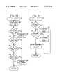
- Fast charging of the battery pack 22is monitored by the CHECK FC TERM subroutine illustrated in FIG. 13.
- This subroutineis identified as task 226 in FIG. 7. It is used to determine if fast charge status has been terminated. More particularly, the duty cycle of the on-board PWM is set for fast charge any time the computer system 26 is off when the battery charging system 24 is connected in order to charge the battery pack 22 as quickly as possible. Initially in steps 288 and 290, the ratio of ⁇ temperature/ ⁇ time is checked to determine if it is within acceptable limits. If not, the system indicates in step 292 that the battery capacity is 100% in step 292. A such, the fast charging is terminated in step 294 by setting the duty cycle of the PWM signal to zero.
- step 296the battery voltage is then checked in step 296 to determine whether it is within acceptable limits. If not, the system proceeds to step 294 and terminates fast charging. If so, the system proceeds to step 298 to determine whether the battery temperature is within acceptable limits to avoid overheating and damage to the battery pack 22. If not, the system proceeds to step 294 to terminate fast charging. If so, the system proceeds to step 300 where the ratio ⁇ voltage/ ⁇ time is checked. If the ratio of ⁇ voltage/ ⁇ time is acceptable, the system returns. If not, the fast charging is terminated in step 294.
- the subroutine in FIG. 14calculates the self-discharge of the battery pack. This subroutine corresponds to task 230 illustrated in FIG. 7. Initially, the system checks in step 302 to determine if the microcontroller 62 is in a suspend mode. If so, the SUSPEND DISCHARGE VALUE is set in step 304. If not, the system proceeds to step 306 where the system determines if the microcontroller 62 is in the stand-by mode. If so, the system proceeds to step 308 and sets the STAND-BY DISCHARGE VALUE. If the system is neither in the suspend mode or stand-by mode, the battery pack hardware discharge value is set in step 310. This subroutine 23 is used to reduce the power drain on the battery pack 22 during conditions when the microcontroller 62 is in either a suspend mode or a stand-by mode.
- FIG. 15illustrates a subroutine for checking the system for battery discharge warnings.
- This subroutinecorresponds to task 234 illustrated in FIG. 7.
- the battery voltageis averaged in step 312.
- the averaged battery voltageis then compared with a first predetermined value representative of a pre-selected battery-low value in step 314. If the averaged battery voltage is greater than the battery-low voltage, the system indicates that the battery is OK in step 316. If not, the system then checks, in step 318 to determine whether the voltage is greater than a battery critical value. If so, the system indicates a battery low condition in step 320. If not, the voltage is then compared with a battery shut-down value in step 322.
- step 324the system indicates in step 324 that the battery is critical. If the voltage is less than the battery shut-down value, the system proceeds to step 326 where the averaged battery voltage is compared with the battery dead value. If the averaged battery voltage is greater than the battery dead value, the system indicates a battery shut down in step 328. If not, the INHIBIT line is set and the battery pack 22 is shut down in step 330.
- the subroutine illustrated in FIG. 16is used to determine the remaining capacity of the battery pack 22. This subroutine corresponds to task 238 illustrated in FIG. 7. This subroutine operates on the principal of measuring the current load demand of the computer system 26 as sensed by the current sensing resistor 48 to determine the remaining capacity of the battery charger system 24.
- step 330the integrator value from the dual-slope off-chip ADC 110 is obtained. The system then determines whether the integrator value is positive in step 332. If the integrator value is positive, the new capacity is determined by adding the integrator value obtained in step 330 to the previous NEW CAPACITY value in step 334. If the integrator value is negative, the integrator value is subtracted from the capacitor in step 336.
- the subroutine illustrated in FIG. 17is used to check for battery discharge warnings.
- this subroutinecorresponds to task 242 illustrated in FIG. 7.
- the battery levels discussed beloware obtained from the CHK DISCHARGE subroutine 234 illustrated in FIG. 15.
- SCPsystem control processor
- FIG. 18relates to a subroutine for communication between the microcontroller 62 and a general-purpose hardware interrupt (GPHI), located in the computer system 26.
- GPHIgeneral-purpose hardware interrupt
- step 354the GPHI data byte is obtained from the computer system 26.
- step 356the system decodes the GPHI data byte. If the data byte corresponds to F0h, a firmware revision byte is set to the GPHI in step 358. If the GPHI byte is other than F0h and, in particular, if the system determines in step 360 that the GPHI byte is F1h, four debug data bytes are sent to the GPHI in step 362. If not, an acknowledge is sent to the GPHI in step 364. Subsequently, in step 366, the GPHI byte is decoded and the various flags are set.
- FIG. 19illustrates a timer interrupt routine for controlling the dual slope A/D converter for converting the voltage across the current sensing resistor 48 to a digital value.
- This subroutineis identified with the reference numeral 368 and begins in step 370 by determining if the integrator 110 is valid. If the integrator 110 is determined to be valid, the system proceeds to step 372. The validity of the integrator 110 is determined by checking the internal timer used to control the dual-slope integration. If the integrator 110 is determined to not be valid, the two second timer is incremented in step 374. Subsequently, the system checks in step 376 to determine if the two second timer has expired. If not, the system proceeds to step 372.
- step 378the system indicates that the integrator 110 is valid in step 378 and proceeds to step 380 to get the integrator value.
- step 380the integrator 110 is restarted in step 382.
- step 372the system initiates counting of minutes in order to ensure that the fast charging is limited to a predetermined number of minutes to avoid overheating and damage to the battery pack 22.
- step 374the system initiates counting of minutes in order to ensure that the fast charging is limited to a predetermined number of minutes to avoid overheating and damage to the battery pack 22.
- step 374determine if the computer power system 26 and battery charger system 24 are both on in step 374. If not, the system proceeds to step 376. If so, the duty cycle of the pulse width modulated signal is checked to determine if it is set at a trickle charge rate in step 378.
- step 380determines if the battery pack 22 is being fast charged. If not, the system proceeds to step 376. If so, the system checks in step 382 to determine if the fast charge timer has timed out. If not, the system proceeds to step 376. If so, the fast charging is terminated in step 384.
Landscapes
- Engineering & Computer Science (AREA)
- Power Engineering (AREA)
- Physics & Mathematics (AREA)
- General Physics & Mathematics (AREA)
- Manufacturing & Machinery (AREA)
- Chemical & Material Sciences (AREA)
- Chemical Kinetics & Catalysis (AREA)
- Electrochemistry (AREA)
- General Chemical & Material Sciences (AREA)
- Microelectronics & Electronic Packaging (AREA)
- Charge And Discharge Circuits For Batteries Or The Like (AREA)
Abstract
Description
Claims (12)
Priority Applications (1)
| Application Number | Priority Date | Filing Date | Title |
|---|---|---|---|
| US08/858,202US5847546A (en) | 1992-11-13 | 1997-05-14 | System and apparatus for generating a continuosly variable reference signal for controlling battery cell charging |
Applications Claiming Priority (4)
| Application Number | Priority Date | Filing Date | Title |
|---|---|---|---|
| US07/975,879US5629604A (en) | 1992-11-13 | 1992-11-13 | Computer power supply system |
| US08/245,004US5541490A (en) | 1992-11-13 | 1994-05-18 | Computer power supply system |
| US47575695A | 1995-06-05 | 1995-06-05 | |
| US08/858,202US5847546A (en) | 1992-11-13 | 1997-05-14 | System and apparatus for generating a continuosly variable reference signal for controlling battery cell charging |
Related Parent Applications (1)
| Application Number | Title | Priority Date | Filing Date |
|---|---|---|---|
| US47575695AContinuation | 1992-11-13 | 1995-06-05 |
Publications (1)
| Publication Number | Publication Date |
|---|---|
| US5847546Atrue US5847546A (en) | 1998-12-08 |
Family
ID=25523527
Family Applications (6)
| Application Number | Title | Priority Date | Filing Date |
|---|---|---|---|
| US07/975,879Expired - LifetimeUS5629604A (en) | 1992-11-13 | 1992-11-13 | Computer power supply system |
| US08/245,004Expired - LifetimeUS5541490A (en) | 1992-11-13 | 1994-05-18 | Computer power supply system |
| US08/245,684Expired - LifetimeUS5561361A (en) | 1992-11-13 | 1994-05-18 | Computer power supply and battery recharging system |
| US08/858,202Expired - LifetimeUS5847546A (en) | 1992-11-13 | 1997-05-14 | System and apparatus for generating a continuosly variable reference signal for controlling battery cell charging |
| US08/856,488Expired - LifetimeUS5838141A (en) | 1992-11-13 | 1997-05-14 | Method for generating a continuously variable reference signal for controlling battery cell charging |
| US08/956,618Expired - LifetimeUS5883497A (en) | 1992-11-13 | 1997-09-18 | Battery fuel gauge |
Family Applications Before (3)
| Application Number | Title | Priority Date | Filing Date |
|---|---|---|---|
| US07/975,879Expired - LifetimeUS5629604A (en) | 1992-11-13 | 1992-11-13 | Computer power supply system |
| US08/245,004Expired - LifetimeUS5541490A (en) | 1992-11-13 | 1994-05-18 | Computer power supply system |
| US08/245,684Expired - LifetimeUS5561361A (en) | 1992-11-13 | 1994-05-18 | Computer power supply and battery recharging system |
Family Applications After (2)
| Application Number | Title | Priority Date | Filing Date |
|---|---|---|---|
| US08/856,488Expired - LifetimeUS5838141A (en) | 1992-11-13 | 1997-05-14 | Method for generating a continuously variable reference signal for controlling battery cell charging |
| US08/956,618Expired - LifetimeUS5883497A (en) | 1992-11-13 | 1997-09-18 | Battery fuel gauge |
Country Status (1)
| Country | Link |
|---|---|
| US (6) | US5629604A (en) |
Cited By (19)
| Publication number | Priority date | Publication date | Assignee | Title |
|---|---|---|---|---|
| US6291968B1 (en) | 2000-05-08 | 2001-09-18 | Lear Corporation | System for automatically charging the battery of a remote transmitter for use in a vehicle security system |
| US20030085621A1 (en)* | 1997-11-17 | 2003-05-08 | Potega Patrick Henry | Power supply methods and configurations |
| US20040130293A1 (en)* | 2003-01-02 | 2004-07-08 | Cho Sung-Mun | Digital device with rechargeable battery and recharging method thereof |
| US20040263123A1 (en)* | 2003-06-24 | 2004-12-30 | Dell Products L.P. | Battery and system power selector integration scheme |
| US20050001589A1 (en)* | 2003-07-03 | 2005-01-06 | Dell Products L.P. | Encrypted response smart battery |
| US20050024016A1 (en)* | 2003-07-29 | 2005-02-03 | Dell Products L.P. | AC-DC adapter and battery charger integration scheme |
| US20050275381A1 (en)* | 2004-06-09 | 2005-12-15 | Guang Huang T | Battery charger with dual use microprocessor |
| US20060033470A1 (en)* | 2003-07-29 | 2006-02-16 | Dell Products L.P. | Information handling system including a battery that reduces a voltage fluctuation |
| US20060132140A1 (en)* | 2004-12-17 | 2006-06-22 | Visteon Global Technologies, Inc. | Circuit to measure vehicle battery voltage |
| US20060152194A1 (en)* | 2005-01-13 | 2006-07-13 | Ligong Wang | Systems and methods for regulating pre-charge current in a battery system |
| US20060158156A1 (en)* | 2005-01-17 | 2006-07-20 | Paul Gamboa | Method and apparatus for charging and discharging a rechargeable battery |
| US20060181244A1 (en)* | 2005-02-16 | 2006-08-17 | Shiguo Luo | Systems and methods for integration of charger regulation within a battery system |
| US20080074080A1 (en)* | 2006-09-26 | 2008-03-27 | Shiguo Luo | Battery systems for information handling systems |
| US20080203817A1 (en)* | 2007-02-22 | 2008-08-28 | Shiguo Luo | Power architecture for battery powered remote devices |
| US20100277129A1 (en)* | 2009-04-29 | 2010-11-04 | Motorola, Inc. | Method and apparatus for controlling charging of a battery in a communication device |
| USRE42114E1 (en) | 1994-12-26 | 2011-02-08 | Fujitsu Semiconductor Limited | Control system for charging batteries and electronic apparatus using same |
| US20110221397A1 (en)* | 2010-03-11 | 2011-09-15 | Chia-Han Chan | Battery Charging Circuit And Charging Method Thereof |
| US20130266041A1 (en)* | 2012-04-04 | 2013-10-10 | Honeywell International Inc. | Pulse width modulation output digital temperature sensor device |
| US11391632B2 (en)* | 2017-08-15 | 2022-07-19 | Robert Bosch Gmbh | Temperature sensor circuit |
Families Citing this family (145)
| Publication number | Priority date | Publication date | Assignee | Title |
|---|---|---|---|---|
| US6369576B1 (en) | 1992-07-08 | 2002-04-09 | Texas Instruments Incorporated | Battery pack with monitoring function for use in a battery charging system |
| US6107802A (en)* | 1992-07-08 | 2000-08-22 | Matthews; Wallace Edward | Battery pack with monitoring function utilizing association with a battery charging system |
| US5629604A (en)* | 1992-11-13 | 1997-05-13 | Zenith Data Systems Corporation | Computer power supply system |
| US6274950B1 (en)* | 1994-03-03 | 2001-08-14 | American Power Conversion | Battery communication system |
| JPH08146105A (en)* | 1994-11-25 | 1996-06-07 | Yazaki Corp | Battery discharge characteristic calculation method and battery residual capacity measuring device |
| JP3303155B2 (en)* | 1995-01-19 | 2002-07-15 | 京セラ株式会社 | Battery charger |
| KR0169392B1 (en)* | 1995-04-24 | 1999-04-15 | 김광호 | Delta voltage detection rapid charging system |
| US5780992A (en)* | 1995-08-09 | 1998-07-14 | Norand Corporation | Rechargeable battery system adaptable to a plurality of battery types |
| US5774733A (en)* | 1995-10-03 | 1998-06-30 | Microchip Technology Incorporated | Microcontroller with analog front-end for providing intelligent battery management |
| US5787294A (en)* | 1995-10-13 | 1998-07-28 | Vlsi Technology, Inc. | System for reducing the power consumption of a computer system and method therefor |
| US5698964A (en)* | 1995-10-20 | 1997-12-16 | Dell Usa, L.P. | Adaptive power battery charging apparatus |
| US5903137A (en)* | 1995-12-15 | 1999-05-11 | Compaq Computer Corporation | Battery pack with single charge inhibit/regulator transistor |
| US5764028A (en)* | 1995-12-15 | 1998-06-09 | Compaq Computer Corporation | Battery pack with single charge-inhibit/regulator transistor |
| DE19609140A1 (en)* | 1996-03-08 | 1997-09-18 | Nokia Mobile Phones Ltd | Charging circuit |
| US5723970A (en)* | 1996-04-05 | 1998-03-03 | Linear Technology Corporation | Battery charging circuitry having supply current regulation |
| US5751134A (en)* | 1996-05-16 | 1998-05-12 | Itronix Corporation | Gas gauging system and method for monitoring battery capacity for battery powered electronic devices |
| JP3580828B2 (en)* | 1996-05-21 | 2004-10-27 | 松下電器産業株式会社 | Pulse charging method and charging device |
| US5867008A (en)* | 1996-06-05 | 1999-02-02 | Double-Time Battery Corporation | Overcharge protection circuitry for rechargeable battery pack |
| US5754027A (en)* | 1996-07-08 | 1998-05-19 | Motorola, Inc. | Battery pack and associated charging system |
| DE29611978U1 (en)* | 1996-07-10 | 1997-02-13 | Muntermann, Axel, 35583 Wetzlar | accumulator |
| US5684382A (en)* | 1996-07-19 | 1997-11-04 | Compaq Computer Corporation | Control of computer AC adapter output voltage via battery pack feedback |
| US5780991A (en)* | 1996-07-26 | 1998-07-14 | Telxon Corporation | Multiple station charging apparatus with single charging power supply for parallel charging |
| US5734253A (en)* | 1996-07-26 | 1998-03-31 | Telxon Corporation | Multiple station charging apparatus with stored charging algorithms |
| US5900718A (en)* | 1996-08-16 | 1999-05-04 | Total Battery Management, | Battery charger and method of charging batteries |
| US5804894A (en)* | 1996-08-16 | 1998-09-08 | Telxon Corporation | Low voltage battery pack monitoring circuit with adjustable set points |
| US5736831A (en)* | 1996-08-22 | 1998-04-07 | Northrop Grumman Corporation | Power limiting circuit for electric vehicle battery charger |
| US5773963A (en)* | 1996-08-29 | 1998-06-30 | Apple Computer Inc. | Method and apparatus for programmably adjusting output voltage of a battery charger |
| JP2836600B2 (en)* | 1996-09-03 | 1998-12-14 | 日本電気株式会社 | Mobile terminal device |
| US5744939A (en)* | 1996-09-05 | 1998-04-28 | Telxon Corp. | Temperature compensation monitoring circuit for a battery pack charging apparatus |
| US5814973A (en)* | 1996-09-20 | 1998-09-29 | Ericsson Inc. | Power unit and charger for a battery powered electrical apparatus and method |
| DE69625714T2 (en)* | 1996-10-10 | 2004-05-13 | Chartec Laboratories A/S | DIGITALLY CONTROLLED POWER SUPPLY FOR CHARGING RECHARGEABLE BATTERIES |
| KR100263551B1 (en)* | 1996-10-12 | 2000-08-01 | 윤종용 | Secondary battery charging circuit |
| KR100265709B1 (en)* | 1996-10-15 | 2000-09-15 | 윤종용 | A secondary charginf apparatus |
| US5864223A (en)* | 1996-11-05 | 1999-01-26 | Meyer; Dennis R. | Battery life extender apparatus |
| KR100222074B1 (en)* | 1996-12-17 | 1999-10-01 | 윤종용 | Constant power charging circuit and portable computer using the same |
| JP3368163B2 (en)* | 1996-12-18 | 2003-01-20 | インターナショナル・ビジネス・マシーンズ・コーポレーション | Power supply for electronic equipment and electronic equipment |
| DE19718781A1 (en)* | 1997-05-03 | 1998-11-05 | Vb Autobatterie Gmbh | Electric accumulator |
| US5818200A (en)* | 1997-05-06 | 1998-10-06 | Dell U.S.A., L.P. | Dual smart battery detection system and method for portable computers |
| JP3017128B2 (en)* | 1997-05-13 | 2000-03-06 | 埼玉日本電気株式会社 | Charge control device |
| KR100539035B1 (en)* | 1997-05-23 | 2005-12-27 | 소니 가부시끼 가이샤 | Battery pack, electronic device system, and method of detecting attachment of battery pack |
| US6018229A (en)* | 1997-06-30 | 2000-01-25 | Compaq Computer Corporation | Lithium-ion battery pack with integral switching regulator using cutoff transistor |
| KR100254776B1 (en)* | 1997-08-25 | 2000-05-01 | 윤종용 | Charging and discharging method of an electronic device having a smart battery |
| US5945806A (en)* | 1997-08-29 | 1999-08-31 | Compaq Computer Corporation | Variable-voltage programmable battery module |
| FR2769143A1 (en)* | 1997-09-26 | 1999-04-02 | Philips Electronics Nv | TELEPHONE EQUIPMENT WITH RECHARGEABLE BATTERY AND DETECTION OF THE TYPE OF CHARGER USED |
| US5917305A (en)* | 1997-12-11 | 1999-06-29 | Compaq Computer Corporation | Battery control architecture with standardized language |
| JP4339423B2 (en) | 1998-02-13 | 2009-10-07 | ソニー株式会社 | Battery pack, battery system, and charging control method for battery system |
| US6031353A (en)* | 1998-02-25 | 2000-02-29 | Ericsson, Inc. | Method and apparatus for communicating battery pack information |
| US6163131A (en)* | 1998-04-02 | 2000-12-19 | The Procter & Gamble Company | Battery having a built-in controller |
| US6198250B1 (en) | 1998-04-02 | 2001-03-06 | The Procter & Gamble Company | Primary battery having a built-in controller to extend battery run time |
| US6118248A (en)* | 1998-04-02 | 2000-09-12 | The Procter & Gamble Company | Battery having a built-in controller to extend battery service run time |
| US6074775A (en)* | 1998-04-02 | 2000-06-13 | The Procter & Gamble Company | Battery having a built-in controller |
| US6835491B2 (en) | 1998-04-02 | 2004-12-28 | The Board Of Trustees Of The University Of Illinois | Battery having a built-in controller |
| US5969507A (en)* | 1998-04-06 | 1999-10-19 | Meyer; Dennis R. | Battery life extender apparatus |
| KR100281528B1 (en)* | 1998-04-29 | 2001-02-15 | 윤종용 | Power supply circuit |
| US6191552B1 (en) | 1999-01-25 | 2001-02-20 | Dell Usa, L.P. | External universal battery charging apparatus and method |
| DE60030424D1 (en)* | 1999-03-23 | 2006-10-12 | Advanced Energy Ind Inc | DC-POWERED COMPUTER SYSTEM WITH A HIGH-FREQUENCY SWITCHING POWER SUPPLY |
| US6172891B1 (en) | 1999-03-26 | 2001-01-09 | Dell Usa, L.P. | AC voltage adapter with integrated DC voltage power supply connector |
| US6331936B1 (en) | 1999-04-14 | 2001-12-18 | Dell Usa, L.P. | AC adapter for a module bay in a computer system |
| US6483275B1 (en) | 1999-04-23 | 2002-11-19 | The Board Of Trustees Of The Univesity Of Illinois | Consumer battery having a built-in indicator |
| US6118254A (en)* | 1999-07-30 | 2000-09-12 | Compaq Computer Corporation | Battery charge control architecture for constant voltage maximum power operation |
| US6172481B1 (en) | 1999-09-02 | 2001-01-09 | Qualcomm Incorporated | Method and apparatus for rapid charging batteries under sub-optimal interconnect conditions |
| DE19944737A1 (en)* | 1999-09-17 | 2001-03-29 | Siemens Ag | Method of charging an accumulator |
| US6426607B1 (en)* | 1999-11-04 | 2002-07-30 | Stmicroelectronics, Inc. | Programmable system and method for regulating an alternator |
| US6324339B1 (en)* | 1999-11-29 | 2001-11-27 | Eveready Battery Company, Inc. | Battery pack including input and output waveform modification capability |
| US6333602B1 (en) | 1999-12-14 | 2001-12-25 | Exfo Photonic Solutions Inc. | Smart light source with integrated operational parameters data storage capability |
| EP1128517A3 (en)* | 2000-02-24 | 2003-12-10 | Makita Corporation | Adapters for rechargeable battery packs |
| US6348777B1 (en)* | 2000-02-29 | 2002-02-19 | Alaris Medical Systems, Inc. | Power management system |
| US6445086B1 (en)* | 2000-06-28 | 2002-09-03 | David H. Houston | Electronic power supply for personal computer and method |
| US7265520B2 (en)* | 2000-08-11 | 2007-09-04 | Seiko Epson Corporation | Electronic apparatus and method of controlling the electronic apparatus |
| US7103694B2 (en) | 2000-09-08 | 2006-09-05 | Hewlett-Packard Development Company, L.P. | Method and apparatus implementing a tuned stub SCSI topology |
| US6469474B2 (en)* | 2000-09-08 | 2002-10-22 | Compaq Information Technologies Group, L.P. | Battery gauge using a resettable decrementer in a DIMM |
| US7007184B2 (en)* | 2000-09-08 | 2006-02-28 | Hewlett-Packard Development Company, L.P. | DIMM connector accomodating sideband signals for battery status and/or control |
| US20020080541A1 (en)* | 2000-09-08 | 2002-06-27 | Bunker M. Scott | Removable battery pack for a cache card |
| EP1202457B1 (en)* | 2000-10-30 | 2003-08-06 | Sony International (Europe) GmbH | Method and software for switching off battery supplied electronic devices and mobile telephone equipped therewith |
| US6978386B2 (en) | 2000-12-28 | 2005-12-20 | Ge Fanuc Automation North America, Inc. | Method and apparatus for regulating current for programmable logic controllers |
| EP1253696A1 (en) | 2001-04-25 | 2002-10-30 | TELEFONAKTIEBOLAGET L M ERICSSON (publ) | A method of charging a battery |
| WO2002089287A1 (en)* | 2001-04-25 | 2002-11-07 | Telefonaktiebolaget L M Ericsson (Publ) | A method of charging a battery |
| US6404164B1 (en) | 2001-05-14 | 2002-06-11 | Hewlett-Packard Company | Method of battery chemistry identification through analysis of voltage behavior |
| JP2004521365A (en)* | 2001-06-29 | 2004-07-15 | ローベルト ボツシユ ゲゼルシヤフト ミツト ベシユレンクテル ハフツング | Method for determining the state of charge and / or power of a charge accumulator |
| US6400123B1 (en) | 2001-08-29 | 2002-06-04 | Hewlett-Packard Company | Battery fuel gauging using battery chemistry identification |
| US6983212B2 (en) | 2001-11-27 | 2006-01-03 | American Power Conversion Corporation | Battery management system and method |
| DE60331195D1 (en)* | 2002-06-12 | 2010-03-25 | Sony Corp | BATTERY PACK AND METHOD FOR CALCULATING THE REMAINING BATTERY CAPACITY |
| US6867604B2 (en) | 2002-06-28 | 2005-03-15 | International Business Machines Corporation | Apparatus for accurately measuring battery voltage |
| US6937947B2 (en)* | 2002-08-20 | 2005-08-30 | Lsi Logic Corporation | Battery charger system and method for providing detailed battery status and charging method information |
| US6888337B2 (en)* | 2003-03-04 | 2005-05-03 | Hewlett-Packard Development Company, L.P. | Power system and method |
| US20050062457A1 (en)* | 2003-09-18 | 2005-03-24 | Texas Instruments Incorporated | Battery charger interface architecture suitable for digital process |
| TWI264169B (en)* | 2003-12-15 | 2006-10-11 | Qqe Technology Co Ltd | Charger with displaying charging amount of rechargeable battery |
| EP1544917A1 (en) | 2003-12-15 | 2005-06-22 | Dialog Semiconductor GmbH | Integrated battery pack with lead frame connection |
| US20050189915A1 (en)* | 2004-02-18 | 2005-09-01 | Quartex, Inc. | Battery arrangement |
| US20050184705A1 (en)* | 2004-02-20 | 2005-08-25 | Gawell George R. | Method and system for providing a trickle charging current to a battery |
| US7019542B2 (en)* | 2004-04-06 | 2006-03-28 | Cadex Electronics Inc. | Method and apparatus for battery testing |
| CN100351740C (en)* | 2004-06-11 | 2007-11-28 | 仁宝电脑工业股份有限公司 | Battery management method and device thereof |
| US7301307B2 (en)* | 2004-06-25 | 2007-11-27 | Nokia Corporation | Method and apparatus to charge a battery using determination of battery load current |
| US20060022633A1 (en)* | 2004-07-27 | 2006-02-02 | Nguyen Don J | High rate power source recharging |
| US7234055B2 (en)* | 2004-08-24 | 2007-06-19 | Inventec Corporation | Computer operating booting system making use of multi-buttons |
| SG124315A1 (en)* | 2005-01-31 | 2006-08-30 | Stl Corp | Battery pack |
| US20060186857A1 (en)* | 2005-02-23 | 2006-08-24 | Saft | Rechargeable battery with charge control |
| ES2261074B1 (en)* | 2005-04-13 | 2007-11-16 | Sistemas Integrados De Servicios De Telecontrol, S.L. | BATTERY CHARGING REGENERATION SYSTEM. |
| US20060261783A1 (en)* | 2005-05-23 | 2006-11-23 | Paul Gamboa | Electronic battery module (EBM) with bidirectional DC-DC converter |
| US20060277555A1 (en)* | 2005-06-03 | 2006-12-07 | Damian Howard | Portable device interfacing |
| JP4367416B2 (en)* | 2006-01-13 | 2009-11-18 | 国産電機株式会社 | Battery charge control device |
| CA2602930C (en)* | 2006-09-19 | 2013-08-06 | Hitachi Koki Co., Ltd. | Adaptor, assembly of battery pack and adaptor, and electric tool with the same |
| TW200818572A (en)* | 2006-10-05 | 2008-04-16 | Wistron Corp | Method for adjusting a charging time of an electronic device coupled to a computer system |
| US20080088281A1 (en)* | 2006-10-16 | 2008-04-17 | Paul Christopher R | System and method for battery charging |
| US20080215240A1 (en)* | 2006-12-18 | 2008-09-04 | Damian Howard | Integrating User Interfaces |
| US20080147308A1 (en)* | 2006-12-18 | 2008-06-19 | Damian Howard | Integrating Navigation Systems |
| KR101278975B1 (en)* | 2006-12-29 | 2013-07-02 | 주식회사 엘지화학 | Protective circuit of secondary cell and method for controlling the same |
| US7944182B2 (en)* | 2007-08-03 | 2011-05-17 | American Power Conversion Corporation | Adjustable battery charger for UPS |
| US7931505B2 (en)* | 2007-11-15 | 2011-04-26 | Bose Corporation | Portable device interfacing |
| RU2465811C2 (en) | 2007-12-10 | 2012-11-10 | БАЙЕР ХЕЛТКЭА ЭлЭлСи | Control of quick charging and supply to metre of analytes in fluid medium arranged with battery supply |
| US8120268B2 (en)* | 2008-01-25 | 2012-02-21 | Eveready Battery Company, Inc. | Lighting device and method of control based on chemistry composition of power source |
| US8116105B2 (en) | 2008-02-07 | 2012-02-14 | American Power Conversion Corporation | Systems and methods for uninterruptible power supply control |
| US20090243553A1 (en)* | 2008-03-25 | 2009-10-01 | John Walley | Method and system for power and charging control in a bluetooth headset |
| US8754611B2 (en) | 2008-04-11 | 2014-06-17 | Apple Inc. | Diffusion-limited adaptive battery charging |
| US20100045237A1 (en)* | 2008-08-20 | 2010-02-25 | Shenzhen Elite Electronic Co., Ltd | Multifunctional portable energy storage device |
| US8044640B2 (en)* | 2008-10-07 | 2011-10-25 | Black & Decker Inc. | Method for stepping current output by a battery charger |
| CN102449872B (en)* | 2009-06-29 | 2016-07-06 | 飞思卡尔半导体公司 | Battery charger and electronic installation |
| US8581554B2 (en)* | 2009-07-10 | 2013-11-12 | Schneider Electric It Corporation | Battery charging method and apparatus |
| CN101645523B (en)* | 2009-09-01 | 2012-01-11 | 惠州市蓝微电子有限公司 | Identification method of charger for battery |
| US8604754B2 (en)* | 2009-09-10 | 2013-12-10 | Ivus Industries, Llc | Universal power interface bus |
| TWI396359B (en)* | 2010-03-08 | 2013-05-11 | Hon Hai Prec Ind Co Ltd | Battery charging system and method thereof |
| CN102195299A (en)* | 2010-03-10 | 2011-09-21 | 鸿富锦精密工业(深圳)有限公司 | Battery charging system and method |
| US8793086B2 (en)* | 2011-02-23 | 2014-07-29 | Blackberry Limited | Method and system for detecting power supply source electrical current capacity |
| JP2015039250A (en)* | 2011-06-14 | 2015-02-26 | 株式会社東芝 | Video display device, video display device driving method, and television receiver |
| AR087722A1 (en)* | 2012-08-29 | 2014-04-09 | Exo S A | ELECTRONIC DEVICE FOR CONNECTION TO THE AC POWER NETWORK OF TWO OR MORE CHARGES AND CONNECTION PROCEDURE THAT IS EXECUTED |
| US9081068B2 (en)* | 2012-09-18 | 2015-07-14 | Apple Inc. | Method and apparatus for determining a capacity of a battery |
| US9261540B2 (en) | 2013-03-22 | 2016-02-16 | Emerson Electric Co. | Devices for measuring voltage of a power supply, detection devices, and temperature controllers |
| US9438054B2 (en) | 2013-05-01 | 2016-09-06 | Apple Inc. | Battery charger integrated circuit chip |
| FR3006812A1 (en)* | 2013-06-06 | 2014-12-12 | St Microelectronics Tours Sas | MANAGING THE LIFETIME OF A BATTERY |
| WO2015063334A1 (en)* | 2013-11-04 | 2015-05-07 | Fujitsu Technology Solutions Intellectual Property Gmbh | Circuit arrangement for current monitoring and power supply unit |
| CN104734265B (en)* | 2013-12-24 | 2017-11-03 | 华硕电脑股份有限公司 | Battery charging circuit and battery charging method |
| TWI536706B (en)* | 2014-03-11 | 2016-06-01 | 登騰電子股份有限公司 | Smart power adaptor and control method of power supplay thereof |
| CN106463975B (en) | 2014-06-30 | 2019-02-26 | 惠普发展公司,有限责任合伙企业 | Offset the variation of operational amplifier |
| US9728995B2 (en)* | 2015-04-08 | 2017-08-08 | Intel Corporation | Systems, methods and devices for adaptable battery charging |
| US10326296B2 (en) | 2016-02-01 | 2019-06-18 | Qualcomm Incorporated | Dual-phase operation for concurrently charging a battery and powering a peripheral device |
| US20170222463A1 (en)* | 2016-02-01 | 2017-08-03 | Qualcomm Incorporated | Duty cycle control for charging a battery |
| US10069319B2 (en) | 2016-03-08 | 2018-09-04 | Apple Inc. | Systems and methods for simultaneously charging a battery with multiple power sources |
| US10714956B2 (en) | 2016-04-05 | 2020-07-14 | Adam Gleason | Apparatus, system, and method for battery charging |
| US10124686B2 (en)* | 2016-07-15 | 2018-11-13 | GM Global Technology Operations LLC | Dual inductive/conductive DC-coupled charging system |
| GB2552777B (en) | 2016-07-21 | 2022-06-08 | Petalite Ltd | A battery charging system and method |
| US10286799B2 (en)* | 2016-08-23 | 2019-05-14 | GM Global Technology Operations LLC | Hands-free conductive battery charger for an electric vehicle |
| US10211486B2 (en)* | 2017-02-03 | 2019-02-19 | QDroid Inc. | Battery with built-in wireless communication |
| US10641831B2 (en)* | 2017-08-25 | 2020-05-05 | Schneider Electric It Corporation | Battery current measurement |
| US11892433B2 (en)* | 2021-08-02 | 2024-02-06 | Thermo Finnigan Llc | Electrospray current measurement in the nanospray and microspray regime |
| EP4137831A1 (en)* | 2021-08-20 | 2023-02-22 | Hilti Aktiengesellschaft | Method for determining the health of a battery |
Citations (18)
| Publication number | Priority date | Publication date | Assignee | Title |
|---|---|---|---|---|
| US4413221A (en)* | 1980-12-18 | 1983-11-01 | Christie Electric Corporation | Method and circuit for determining battery capacity |
| US4709202A (en)* | 1982-06-07 | 1987-11-24 | Norand Corporation | Battery powered system |
| US4876513A (en)* | 1988-12-05 | 1989-10-24 | Globe-Union Inc. | Dynamic state-of-charge indicator for a battery and method thereof |
| US4910103A (en)* | 1987-12-10 | 1990-03-20 | Nippon Molicel Corp. | Battery pack for a portable radiotelegraphic unit |
| US4918368A (en)* | 1986-10-29 | 1990-04-17 | Span, Inc. | System for charging batteries and measuring capacities and efficiencies thereof |
| US4965738A (en)* | 1988-05-03 | 1990-10-23 | Anton/Bauer, Inc. | Intelligent battery system |
| US5130659A (en)* | 1990-08-21 | 1992-07-14 | Sloan Jeffrey M | Battery Monitor |
| US5150031A (en)* | 1988-09-30 | 1992-09-22 | Motorola, Inc. | Battery charging system |
| US5166596A (en)* | 1991-08-29 | 1992-11-24 | Motorola, Inc. | Battery charger having variable-magnitude charging current source |
| US5185565A (en)* | 1990-10-01 | 1993-02-09 | Sanyo Electric Co., Ltd. | Charge control apparatus for use with electronic equipment |
| US5200689A (en)* | 1992-01-24 | 1993-04-06 | Compaq Computer Corporation | Battery charge monitor to determine fast charge termination |
| US5248929A (en)* | 1992-04-30 | 1993-09-28 | Murata Machinery, Ltd. | Battery time monitor for cellular telephone |
| US5315228A (en)* | 1992-01-24 | 1994-05-24 | Compaq Computer Corp. | Battery charge monitor and fuel gauge |
| US5325041A (en)* | 1991-08-09 | 1994-06-28 | Briggs James B | Automatic rechargeable battery monitoring system |
| US5341503A (en)* | 1992-04-16 | 1994-08-23 | International Business Machines Corporation | Battery operated computer having improved battery gauge and system for measuring battery charge |
| US5434495A (en)* | 1989-03-31 | 1995-07-18 | Mitsubishi Denki Kabushiki Kaisha | Cognition device for battery residual capacity |
| US5481730A (en)* | 1992-01-24 | 1996-01-02 | Compaq Computer Corp. | Monitoring and control of power supply functions using a microcontroller |
| US5541490A (en)* | 1992-11-13 | 1996-07-30 | Zenith Data Systems Corporation | Computer power supply system |
- 1992
- 1992-11-13USUS07/975,879patent/US5629604A/ennot_activeExpired - Lifetime
- 1994
- 1994-05-18USUS08/245,004patent/US5541490A/ennot_activeExpired - Lifetime
- 1994-05-18USUS08/245,684patent/US5561361A/ennot_activeExpired - Lifetime
- 1997
- 1997-05-14USUS08/858,202patent/US5847546A/ennot_activeExpired - Lifetime
- 1997-05-14USUS08/856,488patent/US5838141A/ennot_activeExpired - Lifetime
- 1997-09-18USUS08/956,618patent/US5883497A/ennot_activeExpired - Lifetime
Patent Citations (19)
| Publication number | Priority date | Publication date | Assignee | Title |
|---|---|---|---|---|
| US4413221A (en)* | 1980-12-18 | 1983-11-01 | Christie Electric Corporation | Method and circuit for determining battery capacity |
| US4709202A (en)* | 1982-06-07 | 1987-11-24 | Norand Corporation | Battery powered system |
| US4918368A (en)* | 1986-10-29 | 1990-04-17 | Span, Inc. | System for charging batteries and measuring capacities and efficiencies thereof |
| US4910103A (en)* | 1987-12-10 | 1990-03-20 | Nippon Molicel Corp. | Battery pack for a portable radiotelegraphic unit |
| US4965738A (en)* | 1988-05-03 | 1990-10-23 | Anton/Bauer, Inc. | Intelligent battery system |
| US5150031A (en)* | 1988-09-30 | 1992-09-22 | Motorola, Inc. | Battery charging system |
| US4876513A (en)* | 1988-12-05 | 1989-10-24 | Globe-Union Inc. | Dynamic state-of-charge indicator for a battery and method thereof |
| US5434495A (en)* | 1989-03-31 | 1995-07-18 | Mitsubishi Denki Kabushiki Kaisha | Cognition device for battery residual capacity |
| US5130659A (en)* | 1990-08-21 | 1992-07-14 | Sloan Jeffrey M | Battery Monitor |
| US5185565A (en)* | 1990-10-01 | 1993-02-09 | Sanyo Electric Co., Ltd. | Charge control apparatus for use with electronic equipment |
| US5325041A (en)* | 1991-08-09 | 1994-06-28 | Briggs James B | Automatic rechargeable battery monitoring system |
| US5166596A (en)* | 1991-08-29 | 1992-11-24 | Motorola, Inc. | Battery charger having variable-magnitude charging current source |
| US5315228A (en)* | 1992-01-24 | 1994-05-24 | Compaq Computer Corp. | Battery charge monitor and fuel gauge |
| US5200689A (en)* | 1992-01-24 | 1993-04-06 | Compaq Computer Corporation | Battery charge monitor to determine fast charge termination |
| US5481730A (en)* | 1992-01-24 | 1996-01-02 | Compaq Computer Corp. | Monitoring and control of power supply functions using a microcontroller |
| US5341503A (en)* | 1992-04-16 | 1994-08-23 | International Business Machines Corporation | Battery operated computer having improved battery gauge and system for measuring battery charge |
| US5248929A (en)* | 1992-04-30 | 1993-09-28 | Murata Machinery, Ltd. | Battery time monitor for cellular telephone |
| US5541490A (en)* | 1992-11-13 | 1996-07-30 | Zenith Data Systems Corporation | Computer power supply system |
| US5561361A (en)* | 1992-11-13 | 1996-10-01 | Zenith Data Systems Corporation | Computer power supply and battery recharging system |
Non-Patent Citations (8)
| Title |
|---|
| Duracell/Intel Smart Battery Specification 1993, 94 234 1098 (OEA 151) Power Supply Control Code Sequence, Apr. 25, 1991.* |
| Duracell/Intel Smart Battery Specification 1993, 94 234-1098 (OEA-151) Power Supply Control Code Sequence, Apr. 25, 1991. |
| Gates Energy Products, Sealed Rechargeable Batteries, Application Manual 1989.* |
| Millman & Halkias, "Integrated Electronics: Analog & Digital Circuits & Systems," 1972, Digital Systems, Sec. 17-20, pp. 665-666. |
| Millman & Halkias, Integrated Electronics: Analog & Digital Circuits & Systems, 1972, Digital Systems, Sec. 17 20, pp. 665 666.* |
| Sanyo Smart Chip Model S1 101 Hybrid IC Fast Charge Control Unit, no date.* |
| Sanyo Smart Chip-Model S1-101 Hybrid IC Fast Charge Control Unit, no date. |
| Specification for A.C. Power Supply, Zenith Data Systems, St. Joseph, MI no date.* |
Cited By (39)
| Publication number | Priority date | Publication date | Assignee | Title |
|---|---|---|---|---|
| USRE43911E1 (en) | 1994-12-26 | 2013-01-08 | Fujitsu Semiconductor Limited | Control system for charging batteries and electronic apparatus using same |
| USRE42114E1 (en) | 1994-12-26 | 2011-02-08 | Fujitsu Semiconductor Limited | Control system for charging batteries and electronic apparatus using same |
| US7002265B2 (en)* | 1997-11-17 | 2006-02-21 | Patrick Henry Potega | Power supply methods and configurations |
| US20030085621A1 (en)* | 1997-11-17 | 2003-05-08 | Potega Patrick Henry | Power supply methods and configurations |
| US6366051B1 (en) | 2000-05-08 | 2002-04-02 | Lear Corporation | System for automatically charging the battery of a remote transmitter for use in a vehicle security system |
| US6291968B1 (en) | 2000-05-08 | 2001-09-18 | Lear Corporation | System for automatically charging the battery of a remote transmitter for use in a vehicle security system |
| US20040130293A1 (en)* | 2003-01-02 | 2004-07-08 | Cho Sung-Mun | Digital device with rechargeable battery and recharging method thereof |
| US7411372B2 (en) | 2003-01-02 | 2008-08-12 | Samsung Electronics Co., Ltd. | Digital device with rechargeable battery and recharging method thereof |
| CN100477443C (en)* | 2003-01-02 | 2009-04-08 | 三星电子株式会社 | Digital device having rechargeable battery and charging method thereof |
| EP1435683A3 (en)* | 2003-01-02 | 2006-03-15 | Samsung Electronics Co., Ltd. | Electronic device with battery charging unit |
| US20040263123A1 (en)* | 2003-06-24 | 2004-12-30 | Dell Products L.P. | Battery and system power selector integration scheme |
| US7982430B2 (en) | 2003-06-24 | 2011-07-19 | Dell Products L.P. | Battery and system power selector integration scheme |
| US7202631B2 (en) | 2003-06-24 | 2007-04-10 | Dell Products L.P. | Battery and system power selector integration scheme |
| US20070132430A1 (en)* | 2003-06-24 | 2007-06-14 | Dell Products L.P. | Battery and system power selector integration scheme |
| US6975092B2 (en) | 2003-07-03 | 2005-12-13 | Dell Products L.P. | Encrypted response smart battery |
| US20050001589A1 (en)* | 2003-07-03 | 2005-01-06 | Dell Products L.P. | Encrypted response smart battery |
| US20060033470A1 (en)* | 2003-07-29 | 2006-02-16 | Dell Products L.P. | Information handling system including a battery that reduces a voltage fluctuation |
| US7545120B2 (en) | 2003-07-29 | 2009-06-09 | Dell Products L.P. | AC-DC adapter and battery charger integration for portable information handling systems |
| US20050024016A1 (en)* | 2003-07-29 | 2005-02-03 | Dell Products L.P. | AC-DC adapter and battery charger integration scheme |
| US7592716B2 (en)* | 2003-07-29 | 2009-09-22 | Dell Products L.P. | Information handling system including a battery that reduces a voltage fluctuation |
| US20050275381A1 (en)* | 2004-06-09 | 2005-12-15 | Guang Huang T | Battery charger with dual use microprocessor |
| US7227337B2 (en) | 2004-06-09 | 2007-06-05 | International Components Corporation | Battery charger with dual use microprocessor |
| US7812569B2 (en)* | 2004-12-17 | 2010-10-12 | Visteon Global Technologies, Inc. | Circuit to measure vehicle battery voltage |
| US20060132140A1 (en)* | 2004-12-17 | 2006-06-22 | Visteon Global Technologies, Inc. | Circuit to measure vehicle battery voltage |
| US20060152194A1 (en)* | 2005-01-13 | 2006-07-13 | Ligong Wang | Systems and methods for regulating pre-charge current in a battery system |
| US7378819B2 (en) | 2005-01-13 | 2008-05-27 | Dell Products Lp | Systems and methods for regulating pulsed pre-charge current in a battery system |
| US20060158156A1 (en)* | 2005-01-17 | 2006-07-20 | Paul Gamboa | Method and apparatus for charging and discharging a rechargeable battery |
| US7541781B2 (en)* | 2005-01-17 | 2009-06-02 | Cobasys, Llc | Method and apparatus for charging and discharging a rechargeable battery |
| US20060181244A1 (en)* | 2005-02-16 | 2006-08-17 | Shiguo Luo | Systems and methods for integration of charger regulation within a battery system |
| US7391184B2 (en) | 2005-02-16 | 2008-06-24 | Dell Products L.P. | Systems and methods for integration of charger regulation within a battery system |
| US20080074080A1 (en)* | 2006-09-26 | 2008-03-27 | Shiguo Luo | Battery systems for information handling systems |
| US7436149B2 (en) | 2006-09-26 | 2008-10-14 | Dell Products L.P. | Systems and methods for interfacing a battery-powered information handling system with a battery pack of a physically separable battery-powered input or input/output device |
| US20080203817A1 (en)* | 2007-02-22 | 2008-08-28 | Shiguo Luo | Power architecture for battery powered remote devices |
| US8129983B2 (en)* | 2009-04-29 | 2012-03-06 | Motorola Solutions, Inc. | Method and apparatus for controlling charging of a battery in a communication device |
| US20100277129A1 (en)* | 2009-04-29 | 2010-11-04 | Motorola, Inc. | Method and apparatus for controlling charging of a battery in a communication device |
| US20110221397A1 (en)* | 2010-03-11 | 2011-09-15 | Chia-Han Chan | Battery Charging Circuit And Charging Method Thereof |
| US20130266041A1 (en)* | 2012-04-04 | 2013-10-10 | Honeywell International Inc. | Pulse width modulation output digital temperature sensor device |
| US8974117B2 (en)* | 2012-04-04 | 2015-03-10 | Honeywell International Inc. | Pulse width modulation output digital temperature sensor device |
| US11391632B2 (en)* | 2017-08-15 | 2022-07-19 | Robert Bosch Gmbh | Temperature sensor circuit |
Also Published As
| Publication number | Publication date |
|---|---|
| US5883497A (en) | 1999-03-16 |
| US5629604A (en) | 1997-05-13 |
| US5541490A (en) | 1996-07-30 |
| US5838141A (en) | 1998-11-17 |
| US5561361A (en) | 1996-10-01 |
Similar Documents
| Publication | Publication Date | Title |
|---|---|---|
| US5847546A (en) | System and apparatus for generating a continuosly variable reference signal for controlling battery cell charging | |
| KR100470249B1 (en) | Battery Chargers, How to Charge Battery Packs and Battery Packs | |
| US6008620A (en) | Battery charging device, method for charging battery pack and battery pack | |
| US4667143A (en) | Battery charger having temperature compensated charge rate | |
| US7714533B2 (en) | Battery charging system and method | |
| US5739667A (en) | Control system for charging batteries and electronic apparatus using same | |
| US6144187A (en) | Power measurement for adaptive battery charger | |
| US5900717A (en) | Rechargeable battery charging circuit | |
| US5523671A (en) | Charging system for battery powered devices | |
| EP0480648B1 (en) | NI-Cad battery charge rate controller | |
| CA2632898C (en) | Charging and power supply for mobile devices | |
| US4714868A (en) | Charging and discharging control circuit for a storage battery | |
| US7548041B2 (en) | Power management circuit and methodology for battery-powered systems | |
| US5898294A (en) | Control loop for pulse charging lithium ion cells | |
| JPH10136578A (en) | Battery charger | |
| US6949912B2 (en) | Enabling circuit for avoiding negative voltage transients | |
| KR20220129735A (en) | Modular battery management system | |
| US7701178B2 (en) | Charge control that keeps constant input voltage supplied to battery pack | |
| KR100209780B1 (en) | Charging apparatus | |
| EP3993263A1 (en) | Device and method for controlling fet | |
| JPH07154928A (en) | Battery charger | |
| JPH09233732A (en) | Charge method of secondary battery, and equipment | |
| JP3235179B2 (en) | battery charger | |
| US20030169050A1 (en) | Battery state monitoring circuit | |
| CN113300428A (en) | Charging circuit, charging device, charging method, charging system, and robot |
Legal Events
| Date | Code | Title | Description |
|---|---|---|---|
| AS | Assignment | Owner name:PACKARD BELL NEC, CALIFORNIA Free format text:ASSIGNMENT OF ASSIGNORS INTEREST;ASSIGNOR:ZENITH DATA SYSTEMS CORPORATION;REEL/FRAME:009075/0073 Effective date:19970320 | |
| STCF | Information on status: patent grant | Free format text:PATENTED CASE | |
| FEPP | Fee payment procedure | Free format text:PAYOR NUMBER ASSIGNED (ORIGINAL EVENT CODE: ASPN); ENTITY STATUS OF PATENT OWNER: LARGE ENTITY | |
| CC | Certificate of correction | ||
| AS | Assignment | Owner name:NEC CORPORATION, JAPAN Free format text:ASSIGNMENT OF ASSIGNORS INTEREST;ASSIGNOR:PACKARD BELL NEC, INC.;REEL/FRAME:011007/0153 Effective date:20000223 | |
| FPAY | Fee payment | Year of fee payment:4 | |
| REMI | Maintenance fee reminder mailed | ||
| FPAY | Fee payment | Year of fee payment:8 | |
| FPAY | Fee payment | Year of fee payment:12 | |
| AS | Assignment | Owner name:WARREN & LEWIS INVESTMENT CORPORATION, VIRGINIA Free format text:ASSIGNMENT OF ASSIGNORS INTEREST;ASSIGNOR:NEC CORPORATION;REEL/FRAME:029216/0855 Effective date:20120903 | |
| AS | Assignment | Owner name:NEC CORPORATION, JAPAN Free format text:NUNC PRO TUNC ASSIGNMENT;ASSIGNORS:WARREN & LEWIS INVESTMENT CORPORATION;COMMIX SYSTEMS, LCC;REEL/FRAME:037209/0592 Effective date:20151019 | |
| AS | Assignment | Owner name:NEC CORPORATION, JAPAN Free format text:CORRECTIVE ASSIGNMENT TO CORRECT THE SECOND CONVEYING PARTY NAME PREVIOUSLY RECORDED AT REEL: 037209 FRAME: 0592. ASSIGNOR(S) HEREBY CONFIRMS THE ASSIGNMENT;ASSIGNORS:WARREN & LEWIS INVESTMENT CORPORATION;COMMIX SYSTEMS, LLC;REEL/FRAME:037279/0685 Effective date:20151019 |