US5847331A - Omnidirectional loudspeaker - Google Patents
Omnidirectional loudspeakerDownload PDFInfo
- Publication number
- US5847331A US5847331AUS08/948,243US94824397AUS5847331AUS 5847331 AUS5847331 AUS 5847331AUS 94824397 AUS94824397 AUS 94824397AUS 5847331 AUS5847331 AUS 5847331A
- Authority
- US
- United States
- Prior art keywords
- low frequency
- driver
- housing
- propagation chamber
- sound propagation
- Prior art date
- Legal status (The legal status is an assumption and is not a legal conclusion. Google has not performed a legal analysis and makes no representation as to the accuracy of the status listed.)
- Expired - Lifetime
Links
Images


Classifications
- H—ELECTRICITY
- H04—ELECTRIC COMMUNICATION TECHNIQUE
- H04R—LOUDSPEAKERS, MICROPHONES, GRAMOPHONE PICK-UPS OR LIKE ACOUSTIC ELECTROMECHANICAL TRANSDUCERS; DEAF-AID SETS; PUBLIC ADDRESS SYSTEMS
- H04R1/00—Details of transducers, loudspeakers or microphones
- H04R1/20—Arrangements for obtaining desired frequency or directional characteristics
- H04R1/32—Arrangements for obtaining desired frequency or directional characteristics for obtaining desired directional characteristic only
- H04R1/34—Arrangements for obtaining desired frequency or directional characteristics for obtaining desired directional characteristic only by using a single transducer with sound reflecting, diffracting, directing or guiding means
- H04R1/345—Arrangements for obtaining desired frequency or directional characteristics for obtaining desired directional characteristic only by using a single transducer with sound reflecting, diffracting, directing or guiding means for loudspeakers
Definitions
- the present inventionrelates to loudspeakers for propagating reproduced or transmitted sound. More particularly, the invention relates to a loudspeaker providing a point source effect together with accurate reproduction of relative low, medium, and high frequency sound.
- the novel speakeris particularly suited for use in an enclosed space having a ceiling, floor, and walls, the speaker being configured to exploit sound reflection from these surfaces to advantage.
- the novel speakeris usable in residential and commercial settings in buildings.
- U.S. Pat. No. 5,086,871issued to Alain Barbe on Feb. 11, 1992, describes a speaker system comprising a parallelepiped enclosing a low range speaker and a high range speaker disposed vertically and facing one another. Each speaker is separated from the other by walls inclined to reflect sound horizontally. A small deflector is disposed between the two individual speakers. Barbe lacks the truncated obeliskoid housing, vertical interior air conduit, and the windowed, covered speaker support member of the present invention.
- U.S. Pat. No. 3,961,684issued to Stanley H. Michael et al. on Jun. 8, 1976, describes a speaker assembly arranged to have a plurality of vertically stacked individual speakers. The uppermost and lowermost speakers are stationary. The intermediate speakers are rotatably mounted. Michael et al. lacks the truncated obeliskoid housing, vertical interior air conduit, and the windowed, covered speaker support member of the present invention.
- the housinghas an upper parabolic reflecting surface cooperating with a generally conical lower reflective surface.
- Haugumlacks the truncated obeliskoid housing, vertical interior air conduit, and the windowed, covered speaker support member of the present invention.
- U.S. Pat. No. 5,115,882issued to D. Grier Woody on May 26, 1992, illustrates a speaker system wherein high and low range drivers are mounted coaxially and vertically, each projecting acoustical energy towards one of two cones. The cones redirect acoustical energy horizontally. The speakers are fully exposed to the exterior of the device, there being no housing per se. Woody lacks the truncated obeliskoid housing, vertical interior air conduit, and the windowed, covered speaker support member of the present invention.
- the present inventionprovides a speaker producing time and phase coherent sound waves propagated radially symmetrically, in a manner similar to that of a point source.
- the enclosureis tuned and ported, generates no back pressure, and has a truncated obeliskoid configuration.
- the apparatusincludes a high frequency range driver, a midrange driver, and a low frequency range driver, all vertically and coaxially arranged.
- the three driversare interconnected by a high fidelity, three way electronic crossover network which distributes appropriate frequency range signals to each driver.
- the high range and midrange driversproject sound upwardly, while the low range driver projects sound downwardly.
- This arrangementresults in a speaker particularly suitable for operating in an enclosed room.
- the novel configurationassures that sound waves will reflect from the ceiling and floor of a room in which the speaker is located, and will converge on each listener in a manner essentially duplicating symmetrical propagation from a point source.
- the housingis configured to preserve integrity of low frequency sound, having a chamber dedicated to receiving low frequency sound, the chamber being particularly suited to such sound. Sound absorbent material absorbs non-coherent reflections within the housing. A tubular conduit controls air migration within the housing, thereby contributing to preservation of low frequency sound. The housing thus passes undistorted, coherent sound to the listening environment.
- the novel speakeris readily and economically fabricated from readily available, conventional materials and components.
- Still another object of the inventionis to control air migration within the low frequency sound chamber.
- FIG. 1is a side elevational view of the invention, rendered mostly in cross section.
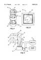
- FIG. 2is an exploded, perspective view of the exterior housing of the invention.
- FIG. 3is a perspective detail view of a member supporting the three drivers employed in the novel speaker.
- FIG. 4is a top plan detail view of the exterior housing of the invention.
- FIG. 5is an electrical schematic illustrating connection of individual drivers to an external source of sound.
- speaker 10propagates phase and time coherent sound waves in the manner of a point source by incorporating the following construction.
- Speaker 10has a relatively high frequency range driver 12, a relatively low frequency range driver 16, and an intermediate frequency range driver 14, all mounted and supported within a driver support member 18 coaxially in vertical orientation.
- High range driver 12 and intermediate range driver 14are disposed upon driver support member 18 to project sound waves in one direction, that is, upwardly, and low frequency driver 16 is disposed upon driver support member 18 to project sound waves in an opposite direction, or downwardly.
- Driver support member 18is mounted within an upper section 20 of a housing 22.
- Housing 22includes a lower section 24 enclosing a low frequency sound propagation chamber 26 disposed below low range driver 16.
- lower section 24enclosing a low frequency sound propagation chamber 26 disposed below low range driver 16.
- housing 22assumes a truncated obeliskoid configuration.
- Caster wheels 28are fixed to and depend from housing 22, whereby speaker 10 may be maneuvered by being wheeled on a floor surface (not shown).
- Truncated obeliskoid configurationis clearly seen in FIG. 2, wherein upper section 20 is seen to comprise an acoustically transmissive material 21, such as a polyester knit fabric, supported on a structural frame 23 having openings to allow sound to pass through material 21 to the exterior of housing 22. Also seen in this view are a support plate 25 to which driver support member 18 (see FIG. 1) may be fixed. Upper section 20 of housing 22 may have a covering (not shown) of acoustically transmissive material located at the top thereof, if desired, to protect the diaphragm of driver 12.
- Member 18is formed from a material such as a synthetic resin similar to acrylonitrile butadiene styrene (ABS) or polyvinyl chloride (PVC), so that member 18 has only sound reflective exposed surfaces.
- Member 18is generally tubular, having a partially tubular lateral wall 30 including openings 32 formed in wall 30 such that sound generated by driver 14 can escape from member 18, and pass through upper section 20 of housing 22.
- the exterior surface of wall 30is preferably lined with acoustically transmissive padding (not shown), such as the material employed for covering housing 22.
- each driver 12, 14, or 16is mounted to an associated plate 13, 15, or 17 fixed to member 18.
- Plates 13, 15, 17are similar to plate 25 of housing lower section 24 in that they cooperate with driver support member 18 and have openings for passing sound vertically from their respective diaphragms.
- Low frequency sound propagation chamber 26has an air conduit 34 projecting thereinto.
- Air conduit 34has a proximal end 36 opening towards low frequency range driver 16 and a distal end 38 opening to and below the exterior of housing 22.
- Air conduit 34extends into low frequency sound propagation chamber 26 more than half of the height of chamber 26, whereby air conduit 34 enables air to migrate within chamber 26 while limiting disruption of air occupying chamber 26.
- Air conduit 34is centrally located within chamber 26, vertically oriented, and, being constructed in a manner generally similar to that of member 18, has only sound reflective exposed surfaces.
- low frequency sound propagation chamber 26has a sound absorbing interior liner 40 having sound absorbency characteristics equivalent to two inch thick cotton batting (not shown). Liner 40 absorbs non-coherent reflections within chamber 26. Liner 40 may, of course, employ different materials. Closed cell synthetic foam sheet of one quarter inch thickness has proved satisfactory.
- lower section 24 of housing 22has a lowermost width, indicated by arrow 42, in a range of sixteen to twenty inches, and preferably eighteen inches, an uppermost width, indicated by arrow 44, in a range of twelve to sixteen inches, and preferably fourteen inches, and a height, indicated by arrow 46, in a range of twenty-two to twenty-seven inches, the height preferably being twenty-four and one half inches.
- Driver support member 18has a diameter, indicated by arrow 48, in a range of eleven to thirteen inches, the diameter preferably being twelve inches.
- Air conduit 34has a height, indicated by arrow 50, in a range of thirteen to fifteen inches, the height preferably being fourteen inches. Diameter of air conduit 34, indicated by arrow 52, is preferably four inches. Proximal end 36 of air conduit 34 is preferably arranged as though cut at a forty-five degree angle to axis 54 of conduit 34. This angle is defined between upper edge 56 of conduit 34 and axis 54.
- FIG. 5shows connection of electrical components of speaker 10 to cooperate with conventional external electrical or electronic components generating and modifying sound being projected by speaker 10.
- a source of sound being projected by speaker 10the source being shown representatively as source output 2, and a representative external amplifier shown at 4, are connected to input terminals 58 of a high fidelity, three way crossover network 60.
- Network 60transmits appropriate frequency signals to drivers 12, 14, 16, thereby reproducing a full spectrum of audible sound with minimal distortion.
- Network 60has three positive terminals 62, 64, 66 which enable connection to coils 68, 70, 72 of respective drivers 12, 14, 16 by conductors 74, 76, 78.
- the negative sides of coils 68, 70, 72are connected in common to a conductor 80 connected to negative terminal 82 of network 60.
- FIG. 1shows a preferred location of crossover network 60 within housing 22. Also shown in FIG. 1 is a terminal assembly 84 enabling ready connection of conductors 6, 8 (see FIG. 5) extending from the source 2 of sound being projected. Location of terminal assembly 84 assures that access for connection is provided without requiring access to the interior of housing 22. Terminal assembly 84 is located at the outer perimeter of housing 22, thereby obviating necessity of tilting speaker 10 when making electrical connections.
Landscapes
- Health & Medical Sciences (AREA)
- Otolaryngology (AREA)
- Physics & Mathematics (AREA)
- Engineering & Computer Science (AREA)
- Acoustics & Sound (AREA)
- Signal Processing (AREA)
- Details Of Audible-Bandwidth Transducers (AREA)
Abstract
Description
Claims (10)
Priority Applications (1)
| Application Number | Priority Date | Filing Date | Title |
|---|---|---|---|
| US08/948,243US5847331A (en) | 1997-10-09 | 1997-10-09 | Omnidirectional loudspeaker |
Applications Claiming Priority (1)
| Application Number | Priority Date | Filing Date | Title |
|---|---|---|---|
| US08/948,243US5847331A (en) | 1997-10-09 | 1997-10-09 | Omnidirectional loudspeaker |
Publications (1)
| Publication Number | Publication Date |
|---|---|
| US5847331Atrue US5847331A (en) | 1998-12-08 |
Family
ID=25487532
Family Applications (1)
| Application Number | Title | Priority Date | Filing Date |
|---|---|---|---|
| US08/948,243Expired - LifetimeUS5847331A (en) | 1997-10-09 | 1997-10-09 | Omnidirectional loudspeaker |
Country Status (1)
| Country | Link |
|---|---|
| US (1) | US5847331A (en) |
Cited By (17)
| Publication number | Priority date | Publication date | Assignee | Title |
|---|---|---|---|---|
| US6186269B1 (en)* | 1998-12-11 | 2001-02-13 | Edward Vollmer | Mini surround sound loudspeaker |
| US6431308B1 (en) | 1998-12-11 | 2002-08-13 | Edward G. Vollmer | High fidelity small omnidirectional loudspeaker |
| US20020134613A1 (en)* | 2001-01-22 | 2002-09-26 | Matsushita Electric Industrial Co., Ltd. | Speaker system |
| RU2209529C1 (en)* | 2002-02-19 | 2003-07-27 | Лебедев Владимир Николаевич | Acoustic system |
| WO2004006621A1 (en)* | 2002-07-09 | 2004-01-15 | Outline Di Noselli G. & C. S.N.C. | Single and multiple reflection wave guide |
| US20040020711A1 (en)* | 2002-08-01 | 2004-02-05 | Hiroshi China | Omnidirectional backload horn-type speaker |
| US6741720B1 (en)* | 2000-04-19 | 2004-05-25 | Russound/Fmp, Inc. | In-wall loudspeaker system |
| US6865785B2 (en) | 1998-11-05 | 2005-03-15 | Matsushita Electric Industrial Co., Ltd. | Method for producing a piezoelectric speaker |
| US20070160246A1 (en)* | 2006-01-09 | 2007-07-12 | Vollmer Edward G | Spherical loudspeaker for omnipresent sound reproduction |
| US20070158134A1 (en)* | 2006-01-11 | 2007-07-12 | Fryette Steven M | Speaker cabinet acoustics control mechanism |
| US20100181141A1 (en)* | 2009-01-22 | 2010-07-22 | Olds Dean W | Video Projection System Mounting Panel |
| US20110051968A1 (en)* | 2009-09-03 | 2011-03-03 | B & W Group Ltd | Loudspeaker enclosures for mounting in an aperture in a cavity wall |
| WO2011053248A1 (en)* | 2009-10-30 | 2011-05-05 | Dream Infotainment Resources Pte Ltd | Omnidirectional speaker |
| USD780720S1 (en)* | 2015-08-20 | 2017-03-07 | Sean Belanger | Speaker motor |
| US10021479B1 (en) | 2005-07-07 | 2018-07-10 | Paul Michael Craig | Non-horizontal multidirectional composite speaker |
| US20190090038A1 (en)* | 2017-09-20 | 2019-03-21 | Mitek Corp., Inc. | Direct fire small ceiling speaker system |
| US10820077B1 (en)* | 2019-04-18 | 2020-10-27 | Deere & Company | Speaker system |
Citations (11)
| Publication number | Priority date | Publication date | Assignee | Title |
|---|---|---|---|---|
| US3483945A (en)* | 1967-08-28 | 1969-12-16 | Musitronic Inc | Omnidirectional sound system |
| US3816672A (en)* | 1970-07-06 | 1974-06-11 | K Peter | Sound reproduction system |
| US3961684A (en)* | 1974-05-23 | 1976-06-08 | Turnsound Corporation | Omni-directional sound system |
| US4336861A (en)* | 1972-08-23 | 1982-06-29 | Peter B Keith | Speaker system |
| US4420061A (en)* | 1980-11-03 | 1983-12-13 | Michael Levy | Pentagonal speaker enclosure with a downward directed dynamic damping system |
| US4440259A (en)* | 1981-08-07 | 1984-04-03 | John Strohbeen | Loudspeaker system for producing coherent sound |
| US5086871A (en)* | 1988-09-29 | 1992-02-11 | Alain Barbe | Omnidirectional electro-accoustical chamber |
| US5115882A (en)* | 1989-03-29 | 1992-05-26 | Woody D Grier | Omnidirectional dispersion system for multiway loudspeakers |
| US5227591A (en)* | 1988-11-08 | 1993-07-13 | Timo Tarkkonen | Loudspeaker arrangement |
| US5436976A (en)* | 1992-12-28 | 1995-07-25 | Dougherty; Donald J. | Omni-directional stereo speaker |
| US5451726A (en)* | 1991-06-25 | 1995-09-19 | Eclipse Research Corporation | Omnidirectional speaker system |
- 1997
- 1997-10-09USUS08/948,243patent/US5847331A/ennot_activeExpired - Lifetime
Patent Citations (11)
| Publication number | Priority date | Publication date | Assignee | Title |
|---|---|---|---|---|
| US3483945A (en)* | 1967-08-28 | 1969-12-16 | Musitronic Inc | Omnidirectional sound system |
| US3816672A (en)* | 1970-07-06 | 1974-06-11 | K Peter | Sound reproduction system |
| US4336861A (en)* | 1972-08-23 | 1982-06-29 | Peter B Keith | Speaker system |
| US3961684A (en)* | 1974-05-23 | 1976-06-08 | Turnsound Corporation | Omni-directional sound system |
| US4420061A (en)* | 1980-11-03 | 1983-12-13 | Michael Levy | Pentagonal speaker enclosure with a downward directed dynamic damping system |
| US4440259A (en)* | 1981-08-07 | 1984-04-03 | John Strohbeen | Loudspeaker system for producing coherent sound |
| US5086871A (en)* | 1988-09-29 | 1992-02-11 | Alain Barbe | Omnidirectional electro-accoustical chamber |
| US5227591A (en)* | 1988-11-08 | 1993-07-13 | Timo Tarkkonen | Loudspeaker arrangement |
| US5115882A (en)* | 1989-03-29 | 1992-05-26 | Woody D Grier | Omnidirectional dispersion system for multiway loudspeakers |
| US5451726A (en)* | 1991-06-25 | 1995-09-19 | Eclipse Research Corporation | Omnidirectional speaker system |
| US5436976A (en)* | 1992-12-28 | 1995-07-25 | Dougherty; Donald J. | Omni-directional stereo speaker |
Cited By (22)
| Publication number | Priority date | Publication date | Assignee | Title |
|---|---|---|---|---|
| US6865785B2 (en) | 1998-11-05 | 2005-03-15 | Matsushita Electric Industrial Co., Ltd. | Method for producing a piezoelectric speaker |
| US6431308B1 (en) | 1998-12-11 | 2002-08-13 | Edward G. Vollmer | High fidelity small omnidirectional loudspeaker |
| US6186269B1 (en)* | 1998-12-11 | 2001-02-13 | Edward Vollmer | Mini surround sound loudspeaker |
| US6741720B1 (en)* | 2000-04-19 | 2004-05-25 | Russound/Fmp, Inc. | In-wall loudspeaker system |
| US20020134613A1 (en)* | 2001-01-22 | 2002-09-26 | Matsushita Electric Industrial Co., Ltd. | Speaker system |
| US6739424B2 (en)* | 2001-01-22 | 2004-05-25 | Matsushita Electric Industrial Co., Ltd. | Speaker system |
| RU2209529C1 (en)* | 2002-02-19 | 2003-07-27 | Лебедев Владимир Николаевич | Acoustic system |
| WO2004006621A1 (en)* | 2002-07-09 | 2004-01-15 | Outline Di Noselli G. & C. S.N.C. | Single and multiple reflection wave guide |
| US20040020711A1 (en)* | 2002-08-01 | 2004-02-05 | Hiroshi China | Omnidirectional backload horn-type speaker |
| US10021479B1 (en) | 2005-07-07 | 2018-07-10 | Paul Michael Craig | Non-horizontal multidirectional composite speaker |
| US8068618B2 (en) | 2006-01-09 | 2011-11-29 | Vollmer Edward G | Spherical loudspeaker for omnipresent sound reproduction |
| US20070160246A1 (en)* | 2006-01-09 | 2007-07-12 | Vollmer Edward G | Spherical loudspeaker for omnipresent sound reproduction |
| US20070158134A1 (en)* | 2006-01-11 | 2007-07-12 | Fryette Steven M | Speaker cabinet acoustics control mechanism |
| US20100181141A1 (en)* | 2009-01-22 | 2010-07-22 | Olds Dean W | Video Projection System Mounting Panel |
| US20110051968A1 (en)* | 2009-09-03 | 2011-03-03 | B & W Group Ltd | Loudspeaker enclosures for mounting in an aperture in a cavity wall |
| US8526655B2 (en) | 2009-09-03 | 2013-09-03 | B & W Group Ltd | Loudspeaker enclosures for mounting in an aperture in a cavity wall |
| WO2011053248A1 (en)* | 2009-10-30 | 2011-05-05 | Dream Infotainment Resources Pte Ltd | Omnidirectional speaker |
| US8750540B2 (en) | 2009-10-30 | 2014-06-10 | Dream Audiolab Pte. Ltd. | Omnidirectional speaker |
| USD780720S1 (en)* | 2015-08-20 | 2017-03-07 | Sean Belanger | Speaker motor |
| US20190090038A1 (en)* | 2017-09-20 | 2019-03-21 | Mitek Corp., Inc. | Direct fire small ceiling speaker system |
| US10911849B2 (en)* | 2017-09-20 | 2021-02-02 | Mitek Corp., Inc. | Direct fire small ceiling speaker system |
| US10820077B1 (en)* | 2019-04-18 | 2020-10-27 | Deere & Company | Speaker system |
Similar Documents
| Publication | Publication Date | Title |
|---|---|---|
| US5847331A (en) | Omnidirectional loudspeaker | |
| JP2673002B2 (en) | Speaker system | |
| US4336861A (en) | Speaker system | |
| US4496021A (en) | 360 Degree radial reflex orthospectral horn for high-frequency loudspeakers | |
| US3816672A (en) | Sound reproduction system | |
| US7324654B2 (en) | Arbitrary coverage angle sound integrator | |
| JP3266604B2 (en) | Speaker system | |
| US4057689A (en) | High fidelity sound reproduction system and modules thereof | |
| US5502772A (en) | Speaker having improved sound square, sound bank, sound angle, sound wedge and sound radiators | |
| US4224469A (en) | Stereo speaker system | |
| US4357490A (en) | High fidelity loudspeaker system for aurally simulating wide frequency range point source of sound | |
| US4619342A (en) | Multiple sound transducer system utilizing an acoustic filter to reduce distortion | |
| US5321756A (en) | Loudspeaker system with sonically powered drivers and centered feedback loudspeaker connected thereto | |
| US7835537B2 (en) | Loudspeaker including slotted waveguide for enhanced directivity and associated methods | |
| US4850452A (en) | Loudspeaker structure | |
| US4553628A (en) | Speaker system | |
| CA1146081A (en) | Sound reproducing systems utilizing acoustic processing unit | |
| CA1083972A (en) | Multiple driver loudspeaker system | |
| US4206831A (en) | Loudspeaker coupler | |
| US4134471A (en) | Narrow angle cylindrical wave full range loudspeaker system | |
| US6431308B1 (en) | High fidelity small omnidirectional loudspeaker | |
| US4231446A (en) | Resonating chamber | |
| JP2791661B2 (en) | Speaker cabinet | |
| US20190058954A1 (en) | Layered speaker assembly | |
| US6425456B1 (en) | Hollow semicircularly curved loudspeaker enclosure |
Legal Events
| Date | Code | Title | Description |
|---|---|---|---|
| STCF | Information on status: patent grant | Free format text:PATENTED CASE | |
| REMI | Maintenance fee reminder mailed | ||
| FPAY | Fee payment | Year of fee payment:4 | |
| SULP | Surcharge for late payment | ||
| AS | Assignment | Owner name:WILLIAM B. HART, SR., CALIFORNIA Free format text:ASSIGNMENT OF ASSIGNORS INTEREST;ASSIGNOR:HART, TERESA (DEC'D );REEL/FRAME:015642/0771 Effective date:20040814 Owner name:OLGA J. HART, CALIFORNIA Free format text:ASSIGNMENT OF ASSIGNORS INTEREST;ASSIGNOR:HART, TERESA (DEC'D );REEL/FRAME:015642/0771 Effective date:20040814 Owner name:HART LIVING TRUST DATED 5/4/93, CALIFORNIA Free format text:ASSIGNMENT OF ASSIGNORS INTEREST;ASSIGNORS:HART SR., WILLIAM B.;HART, OLGA J.;REEL/FRAME:015642/0768 Effective date:20040815 | |
| AS | Assignment | Owner name:NEVADA SOUND SYSTEMS LTD., NEVADA Free format text:ASSIGNMENT OF ASSIGNORS INTEREST;ASSIGNORS:HART, WILLIAM B., SR., TTE;HART, OLGA J.;VOLLMER, EDWARD G., JR.;REEL/FRAME:017176/0382 Effective date:20051019 | |
| REMI | Maintenance fee reminder mailed | ||
| FPAY | Fee payment | Year of fee payment:8 | |
| SULP | Surcharge for late payment | Year of fee payment:7 | |
| REMI | Maintenance fee reminder mailed | ||
| FPAY | Fee payment | Year of fee payment:12 | |
| SULP | Surcharge for late payment | Year of fee payment:11 |