US5846187A - Redo sternotomy retractor - Google Patents
Redo sternotomy retractorDownload PDFInfo
- Publication number
- US5846187A US5846187AUS08/713,924US71392496AUS5846187AUS 5846187 AUS5846187 AUS 5846187AUS 71392496 AUS71392496 AUS 71392496AUS 5846187 AUS5846187 AUS 5846187A
- Authority
- US
- United States
- Prior art keywords
- blunt blade
- retractor
- handle
- blade
- top surface
- Prior art date
- Legal status (The legal status is an assumption and is not a legal conclusion. Google has not performed a legal analysis and makes no representation as to the accuracy of the status listed.)
- Expired - Fee Related
Links
- 210000001562sternumAnatomy0.000claimsabstractdescription29
- 238000000034methodMethods0.000claimsabstractdescription19
- 238000012800visualizationMethods0.000claimsabstractdescription19
- 210000002216heartAnatomy0.000claimsdescription9
- 230000000295complement effectEffects0.000claimsdescription6
- 230000002934lysing effectEffects0.000claimsdescription3
- 210000000115thoracic cavityAnatomy0.000claimsdescription3
- 206010000050Abdominal adhesionsDiseases0.000claimsdescription2
- 210000001664manubriumAnatomy0.000claimsdescription2
- 230000003028elevating effectEffects0.000claims1
- 210000001519tissueAnatomy0.000abstractdescription10
- 238000001356surgical procedureMethods0.000description14
- 230000009089cytolysisEffects0.000description5
- 238000013461designMethods0.000description5
- 208000034693LacerationDiseases0.000description4
- 208000014674injuryDiseases0.000description3
- 210000005241right ventricleAnatomy0.000description3
- 208000027418Wounds and injuryDiseases0.000description2
- 238000013459approachMethods0.000description2
- 230000002612cardiopulmonary effectEffects0.000description2
- 210000004351coronary vesselAnatomy0.000description2
- 230000006378damageEffects0.000description2
- 238000002224dissectionMethods0.000description2
- 239000000463materialSubstances0.000description2
- 210000000779thoracic wallAnatomy0.000description2
- 208000028685Asherman syndromeDiseases0.000description1
- 206010058046Post procedural complicationDiseases0.000description1
- 208000035965Postoperative ComplicationsDiseases0.000description1
- 201000001389adhesions of uterusDiseases0.000description1
- 229910045601alloyInorganic materials0.000description1
- 239000000956alloySubstances0.000description1
- 210000000709aortaAnatomy0.000description1
- 230000003190augmentative effectEffects0.000description1
- 210000003129brachiocephalic veinAnatomy0.000description1
- 230000006837decompressionEffects0.000description1
- 230000003247decreasing effectEffects0.000description1
- 238000011161developmentMethods0.000description1
- 210000001349mammary arteryAnatomy0.000description1
- 239000002184metalSubstances0.000description1
- 238000012986modificationMethods0.000description1
- 230000004048modificationEffects0.000description1
- 230000000399orthopedic effectEffects0.000description1
- 210000003516pericardiumAnatomy0.000description1
- 239000010935stainless steelSubstances0.000description1
- 229910001220stainless steelInorganic materials0.000description1
- 230000000451tissue damageEffects0.000description1
- 231100000827tissue damageToxicity0.000description1
- 230000008733traumaEffects0.000description1
- 210000001113umbilicusAnatomy0.000description1
- 210000003462veinAnatomy0.000description1
- 230000002861ventricularEffects0.000description1
Images
Classifications
- A—HUMAN NECESSITIES
- A61—MEDICAL OR VETERINARY SCIENCE; HYGIENE
- A61B—DIAGNOSIS; SURGERY; IDENTIFICATION
- A61B17/00—Surgical instruments, devices or methods
- A61B17/02—Surgical instruments, devices or methods for holding wounds open, e.g. retractors; Tractors
- A—HUMAN NECESSITIES
- A61—MEDICAL OR VETERINARY SCIENCE; HYGIENE
- A61B—DIAGNOSIS; SURGERY; IDENTIFICATION
- A61B1/00—Instruments for performing medical examinations of the interior of cavities or tubes of the body by visual or photographical inspection, e.g. endoscopes; Illuminating arrangements therefor
- A61B1/32—Devices for opening or enlarging the visual field, e.g. of a tube of the body
- A—HUMAN NECESSITIES
- A61—MEDICAL OR VETERINARY SCIENCE; HYGIENE
- A61B—DIAGNOSIS; SURGERY; IDENTIFICATION
- A61B17/00—Surgical instruments, devices or methods
- A61B2017/0046—Surgical instruments, devices or methods with a releasable handle; with handle and operating part separable
- A—HUMAN NECESSITIES
- A61—MEDICAL OR VETERINARY SCIENCE; HYGIENE
- A61B—DIAGNOSIS; SURGERY; IDENTIFICATION
- A61B90/00—Instruments, implements or accessories specially adapted for surgery or diagnosis and not covered by any of the groups A61B1/00 - A61B50/00, e.g. for luxation treatment or for protecting wound edges
- A61B90/36—Image-producing devices or illumination devices not otherwise provided for
Definitions
- the present inventionrelates to surgical retractors, and in particular, retractors adapted for endoscopic use. More particularly, the invention relates to a retractor for use in retrosternal adhesiolysis.
- An anterior (or ventral) midline sternotomyis the most common surgical approach for coronary artery bypass or valvular repair surgery. Approximately 15% of the coronary artery bypass surgery preformed is a second or third surgery to "redo" or repair a previous bypass or add additional bypass grafts. Likewise, approximately 10% of all valvular surgery is redo surgery. Combined, these figures represent nearly 50,000 cases per year of redo surgery in the United States alone.
- a significant post operative complication of the sternotomy approachis development of retrosternal adhesions between the patient's heart and/or pericardial sac and the anterior chest wall at the incision site. In the event additional coronary surgery becomes necessary, retrosternal adhesions significantly increase the risk of the second or redo sternotomy.
- Complications associated with retrosternal adhesions and the redo sternotomyinclude laceration of the right ventricle which is often adhered to the old sternal incision, laceration of the mammary artery or vein graft, laceration of the aorta, laceration of the innominate vein, or a traction tear of right ventricle after sternotomy, when raising the sternal table.
- Endoscopic visualization of cranially located retrosternal adhesionsoffers a viable alternative for reducing the risks associated with redo sternotomy.
- Endoscopic visualizationwhen successfully achieved, allows pre-sternotomy right ventricular dissection away from the sternal incision, avoids the necessity of cardiopulmonary bypass, and eliminates the risk of traction injury of the right ventricle when the sternal table is elevated.
- the present inventionprovides a hand-held retractor that is adapted for endoscopic use at a predetermined area of a patient.
- the retractor of the inventionis comprised of a longitudinally-extending blade with a proximal end, a distal end, and a top surface.
- a handleis connected to the proximal end of the blade by a separating member.
- the separating memberis configured to allow a surgeon direct access to and visualization of the area adjacent the top surface and distal end of the blade after positioning the distal end of the blade at the predetermined area.
- the present inventionalso provides a method of endoscopic retrosternal adhesiolysis which utilizes a retractor to provide access to and visualization of adhesions adjacent the cranial portion of a patient's sternum while retracting away and protecting underlying tissue.
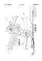
- FIG. 1is a rear perspective view of one embodiment of the retractor of the present invention.
- FIG. 2is a side cross-sectional view of the retractor of FIG. 1 being used in conjunction with a surgical instrument and showing in phantom the handle in an alternate position.
- the present inventioncomprises a retractor 10, preferably a redo sternotomy retractor, having a longitudinally-extending blunt blade 20, a separating member 50, a handle 60, and a means for connecting the handle 60 to the separating member 50.
- a preferred use of the retractoris the dissection of and lysis of retrosternal adhesions, e.g., adhesions between the sternum and heart or pericardium at a previous sternotomy site.
- the retractor 10 of the present inventioncan be used for different surgical procedures, such as lysis of abdominal adhesions, intra-uterine adhesions or other thoracic adhesions and the like, particularly where endoscopic visualization is preferred.
- the blunt blade 20has a longitudinal axis L, a top surface 22, a bottom surface 24, a distal end 26, an opposed proximal end 28, and an edge 30 circumscribing it.
- the preferred material to construct the retractor 10is a stainless steel or a biocompatable metal or alloy that is acceptable for surgery. However, other materials are contemplated, such as plastic.
- the preferred length of the blunt blade 20is about the same as the length of the sternum S of the patient on whom the surgical procedure will be performed, which is approximately ten (10) to twelve (12) inches for an adult patient.
- the length of the blunt blade 20would naturally be shorter, such as between about four (4) to six (6) inches.
- the blunt blade 20is arcuate in cross section. This is preferred because a curved cross section is stronger and more stable compared to a flat profile.
- a blunt blade 20 that is substantially rectangular in cross sectionis contemplated as an alternate embodiment.
- the shape and dimensions, such as length, width, and thickness, of the blunt blade 20can be designed for different, specific surgical procedures. Design factors include the procedure being performed, the structural strength necessary for the blunt blade 20, the desired flexibility of the blunt blade 20, and the predetermined area of the patient's body where the operation will occur. For example, as shown in FIG. 2, an appropriate thickness of the blunt blade 20 is required to ensure a proper operation wherein the distance between the sternum S and the heart H in an adult patient is approximately three (3) to five (5) millimeters.
- the edge 30 of the blunt blade 20 adjacent its distal end 26, or front tip 32is arcuate.
- the front tip 32has a constant curvature.
- An alternate embodimenthas less angularity in the front tip 32, such as a squared "C" shape.
- the edges 30 of the front tip 32should be smooth and blunt, as opposed to having sharp corners, to reduce the chances of tissue damage or other injuries when used during the surgical procedure.
- the blunt blade 20 of the retractor 10repels tissue away from the area of adhesiolysis and protects such tissue from trauma due to electrocautery or sharp dissecting instruments such a scissors or a scalpel.
- the blunt blade 20comprises a first section 34 disposed adjacent the distal end 26 of the blunt blade 20 and an adjacent second section 36, which is shown as encompassing the remainder of the length of the blunt blade 20.
- the top surface 22 of the first section 34 and the second section 36are linear along the longitudinal axis L of the blunt blade 20. At the point where the two sections 34, 36 meet, the top surface 22 is nonlinear.
- the top surfaces 22 of the first and second sections 34, 36are nonlinear with respect to each other and, preferably, the top surface 22 of the first section 34 is lower than the top surface 22 of the second section 36. That is, the top surface 22 of the first section 34 is disposed closer to the bottom surface 24 of the first section 34 than the top surface 22 of the second section 36.
- This design in which the top surface 22 of the section adjacent the front tip 32 is loweris advantageous for use with an endoscopic scope to prevent obstruction of the scope.
- the retractor 10preferably is designed for endoscopic use and further comprises a longitudinally-extending tube 40 defining a bore 42 therethrough.
- the tube 40has a first end 46 disposed adjacent the proximal end 28 of the blunt blade 20, an opposed second end 44, and an outer surface 48. At least a portion of the outer surface 48 is fixedly attached, such as by a weld, to the top surface 22 of the blunt blade 20.
- the bore 42extends substantially parallel to the longitudinal axis L of the blunt blade 20 and is of a size to allow a predetermined surgical instrument 15 to be slidably received therein.
- An example of a surgical instrumentis an endoscope.
- the tube 40securably and stationarily positions the surgical instrument 15 relative to the blunt blade 20 as the retractor 10 is used.
- the diameter of the bore 42is of an appropriate dimension to accommodate a particular endoscope or surgical instrument 15, such as four (4) or five (5) millimeters for standard endoscopic procedures, or two (2) or three (3) millimeters for pediatric surgery. It is also preferred that the retractor 10 further comprises a bayonet-type endoscopic fitting 49 fixedly attached to the first end 46 of the tube 40.
- the fittingmay detachably secure a predetermined surgical instrument 15 (such as an endoscope) slidably received in the tube 40 at a desired longitudinal position.
- Other securing devices known in the artcan similarly be used.
- the separating member 50 of the present inventionhas a bottom end 52, which is fixedly attached to the proximal end 28 of the blunt blade 20, and an opposed top end 54.
- the separating member 50is oriented to allow longitudinal movement of a surgical instrument 15 along at least a portion of the top surface 22 of the blunt blade 20 so that the movement is unobstructed by the separating member 50. That is, the separating member 50 laterally spaces apart the handle 60 from the blunt blade 20 so that a surgical instrument 15 can be passed along the length of the blunt blade 20 without contacting the handle 60 or the separating member 50.
- the separating member 50comprises a ring member 56 having a body portion 58 defining an opening 59 therethrough.
- the opening 59which is circular, specifically an oval, is of a size to allow a surgical instrument 15 to be disposed therethrough unobstructed by the body portion 58.
- the ring member 56can have other shapes, such as a rectangular opening. It is also contemplated that the opening 59 can be small, such as the same as the bore of the tube 40 and longitudinally-aligned with the tube 40.
- separating members 50that laterally space apart the handle 60 from the blunt blade 20 are also contemplated.
- One exampleis a substantially linear member, instead of one with an opening therethrough, that is disposed laterally and substantially parallel to the top surface 22 of the blunt blade 20.
- the handle 60would be located to the side of the blunt blade 20 so that the handle 60 would be aligned sideways instead of over the top surface 22 of the blunt blade 20 as shown in FIGS. 1 and 2.
- the object of the separating memberis to remove the handle from the field of surgery and to give the surgeon the ability to maneuver instruments 15 about the top surface 22 and longitudinal axis L of the blunt blade 20.
- the handle 60has a first end 62 disposed adjacent the top end 54 of the separating member 50 and connected thereto by the connecting, or an attaching, means. As shown in FIG. 2, it is preferred that the handle 60 is rotatable about an axis of rotation R. To allow this rotation, the connecting means further comprises a means for selectively positioning the handle 60 at a selected one of a plurality of desired radial positions about the axis of rotation R.
- the selectively positioning meanscomprises a first member 70 having a lower surface 72 fixedly attached to the top surface 22 of the separating member 50 and a second member 80.
- the second member 80has an exterior surface 82 and is rotatable relative to the first member 70 about the axis of rotation R.
- the first end 62 of the handle 60is fixedly attached to a portion of the exterior surface 82 of the second member 80.
- a portion of the first and second members 70, 80are of a complementary size with each other so that the first and second members 70, 80 may securably and detachably engage each other when the handle 60 and attached second member 80 are disposed at the desired radial position.
- the first member 70comprises at least one cleat 74 and the second member 80 comprises a disk member 84 defining a plurality of slots 86 therein.
- Each slot 86is of a size to complementarily receive one cleat 74 therein.
- the slots 86are disposed radially about the axis of rotation R so that at least one of the slots 86 engages one cleat 74 at each of the desired radial positions.
- each of the two cleats 74engages a respective slot 86 in the disk member 84.
- a first desired radial positionwhich is disposed rearwardly relative to the blunt blade 20 and parallel its longitudinal axis L
- each of the two cleats 74engages a respective slot 86 in the disk member 84.
- a second desired radial positionshown in phantom as 60' in FIG. 2
- each of the two cleats 74again engage a respective slot in the disk member 84.
- the handle 60is disposed for pushing the blunt blade 20 and in the second desired radial position, the handle 60 is disposed for pulling.
- other radial positionsmay be preferred, such as rotating the handle 60 ninety degrees (90°) from the two desired radial positions shown.
- first and second members 70, 80having complementary knurled surfaces or having complementary detents and interfacing protrusions.
- these alternate embodimentscan be constructed to allow the handle 60 to be disposed at numerous desired radial positions.
- the selectively positioning meanscan further comprise a means for rotatably aligning the second member 80 as the second member 80 rotates relative to the first member 70.
- the second member 80defines a passage 88 therethrough that extends along the axis of rotation R.
- the aligning meanscomprises a rod 90 that has an exterior surface 92.
- the rod 90is of a size to be complementarily received into the passage 88 so that the second member 80 and attached handle 60 are rotatable about the rod 90.
- the selectively positioning meansalso comprises a means for locking the second member 80 at the selected desired radial position.
- the locking meanspreferably comprises a nut 94 that defines a duct 96 extending therethrough and that has one side 98 disposed adjacent a portion of the second member 80.
- the duct 96is of a size to receive a portion of the rod 90 therein.
- the duct 96 and the exterior surface 92 of the rod 90also have complementary threaded surfaces so that the nut 94 is movable along the rod 90 between a locking position and a release position.
- the nut 94In the locking position, a portion of the nut 94 contacts a portion of the exterior surface 82 of the second member 80 so that the second member 80 engages the first member 70, even when an upward force is applied to the handle 60.
- the nut 94In the release position, the nut 94 is spaced apart from the second member 80 so that the second member 80 can be separated from the first member 70 and rotated from one desired radial position to another desired radial position.
- the surgeontwists the nut 94 loose so that the handle 60 can be rotated between the first and second desired radial positions and, when in the chosen desired radial position, the surgeon re-tightens the nut 94.
- One embodiment of the inventionprovides a method of lysing a retrosternal adhesion resulting from a previous sternotomy at a predetermined site in a patient.
- "Retrosternal”means the area beneath, behind or adjacent the posterior or dorsal surface of the sternum, i.e., the surface or portion of the sternum facing the thoracic cavity.
- the patientcan be any patient but is preferably a human subject.
- the methodcomprises accessing the retrosternal area through a thoracotomy incision that is adjacent to the anterior (or ventral) midline of the patient near the caudal end of the patient's sternum.
- the previous sternal incisionis incised an the incision is taken down to the sternum sharply or with electrocautery.
- the previous sternal incisionis extended toward the umbilicus approximately two inches below the caudal end of the sternum.
- the rectus faciais then opened in the mid-line to allow access to the retrosternal area.
- a planeis developed behind or underneath the sternum sharply under direct vision. The manubrium is removed if it is present. A rake or a retractor can then be placed at the caudal end of the sternum and the caudal end of the sternum is elevated away from the heart. This creates a slightly wider plane between the sternum and the heart.
- the redo sternotomy retractor 10 provided by the present inventionis then introduced into the plane behind the sternum so that the space between the sternum and underlying tissues can be clearly visualized adjacent the distal end 26 of the blade 20 by application of the appropriate downward pressure to the retractor 10.
- a working space or tunnelis created between the top surface of the blunt blade 20 and the posterior or dorsal surface of the sternum and along the longitudinal axis thereof Underlying tissues are retracted away and protected by the blade 20 as lysis of adhesions is preformed by the surgeon.
- the retractor 10can be adapted for endoscopic attachment. Once connected to an endoscope, retrosternal adhesions are clearly seen on the video screen, especially adhesions which occur near the cranial terminus of the sternum. It is also contemplated that an endoscope can be passaged in the tunnel created between the top surface 22 of the blade 20 and the posterior (or dorsal) surface of the sternum along with other instruments.
- the retrosternal adhesionscan be lysed and divided (dissected away) utilizing electrocautery coupled with suction, preferably under endoscopic control and visualization. As the adhesions are taken down, the retractor 10 is slowly advanced cephalad so that within several minutes the full extent of the retractor 10 is behind the sternum.
Landscapes
- Health & Medical Sciences (AREA)
- Life Sciences & Earth Sciences (AREA)
- Surgery (AREA)
- Molecular Biology (AREA)
- General Health & Medical Sciences (AREA)
- Biomedical Technology (AREA)
- Heart & Thoracic Surgery (AREA)
- Medical Informatics (AREA)
- Nuclear Medicine, Radiotherapy & Molecular Imaging (AREA)
- Animal Behavior & Ethology (AREA)
- Engineering & Computer Science (AREA)
- Public Health (AREA)
- Veterinary Medicine (AREA)
- Physics & Mathematics (AREA)
- Biophysics (AREA)
- Optics & Photonics (AREA)
- Pathology (AREA)
- Radiology & Medical Imaging (AREA)
- Surgical Instruments (AREA)
Abstract
Description
Claims (30)
Priority Applications (6)
| Application Number | Priority Date | Filing Date | Title |
|---|---|---|---|
| US08/713,924US5846187A (en) | 1996-09-13 | 1996-09-13 | Redo sternotomy retractor |
| AU44179/97AAU4417997A (en) | 1996-09-13 | 1997-09-11 | Redo sternotomy retractor |
| EP97942495AEP1011410A4 (en) | 1996-09-13 | 1997-09-11 | Redo sternotomy retractor |
| PCT/US1997/016373WO1998010695A1 (en) | 1996-09-13 | 1997-09-11 | Redo sternotomy retractor |
| CA002265759ACA2265759A1 (en) | 1996-09-13 | 1997-09-11 | Redo sternotomy retractor |
| US08/929,548US5846191A (en) | 1996-09-13 | 1997-09-15 | Redo sternotomy retractor |
Applications Claiming Priority (1)
| Application Number | Priority Date | Filing Date | Title |
|---|---|---|---|
| US08/713,924US5846187A (en) | 1996-09-13 | 1996-09-13 | Redo sternotomy retractor |
Related Child Applications (1)
| Application Number | Title | Priority Date | Filing Date |
|---|---|---|---|
| US08/929,548Continuation-In-PartUS5846191A (en) | 1996-09-13 | 1997-09-15 | Redo sternotomy retractor |
Publications (1)
| Publication Number | Publication Date |
|---|---|
| US5846187Atrue US5846187A (en) | 1998-12-08 |
Family
ID=24868101
Family Applications (2)
| Application Number | Title | Priority Date | Filing Date |
|---|---|---|---|
| US08/713,924Expired - Fee RelatedUS5846187A (en) | 1996-09-13 | 1996-09-13 | Redo sternotomy retractor |
| US08/929,548Expired - Fee RelatedUS5846191A (en) | 1996-09-13 | 1997-09-15 | Redo sternotomy retractor |
Family Applications After (1)
| Application Number | Title | Priority Date | Filing Date |
|---|---|---|---|
| US08/929,548Expired - Fee RelatedUS5846191A (en) | 1996-09-13 | 1997-09-15 | Redo sternotomy retractor |
Country Status (5)
| Country | Link |
|---|---|
| US (2) | US5846187A (en) |
| EP (1) | EP1011410A4 (en) |
| AU (1) | AU4417997A (en) |
| CA (1) | CA2265759A1 (en) |
| WO (1) | WO1998010695A1 (en) |
Cited By (88)
| Publication number | Priority date | Publication date | Assignee | Title |
|---|---|---|---|---|
| US5913818A (en)* | 1997-06-02 | 1999-06-22 | General Surgical Innovations, Inc. | Vascular retractor |
| US6132370A (en)* | 1996-04-26 | 2000-10-17 | Genzyme Corporation | Retractor-mounted coronary stabilizer |
| US6161543A (en) | 1993-02-22 | 2000-12-19 | Epicor, Inc. | Methods of epicardial ablation for creating a lesion around the pulmonary veins |
| US6231506B1 (en) | 1999-05-04 | 2001-05-15 | Cardiothoracic Systems, Inc. | Method and apparatus for creating a working opening through an incision |
| US6290644B1 (en) | 1996-02-20 | 2001-09-18 | Cardiothoracic Systems, Inc. | Surgical instruments and procedures for stabilizing a localized portion of a beating heart |
| US6315717B1 (en) | 1996-02-20 | 2001-11-13 | Cardiothoracic Systems, Inc. | Surgical instruments for stabilizing the beating heart during coronary artery bypass graft surgery |
| US6394951B1 (en) | 1996-02-20 | 2002-05-28 | Cardiothoracic Systems, Inc. | Surgical instruments and procedures for stabilizing the beating heart during coronary artery bypass graft surgery |
| US6406424B1 (en) | 1999-09-16 | 2002-06-18 | Williamson, Iv Warren P. | Tissue stabilizer having an articulating lift element |
| US6482229B1 (en)* | 2000-11-21 | 2002-11-19 | Advanced Medical Optics, Inc. | Anterior chamber intraocular lens having fixation members attached to the cornea and methods of implantation |
| US6511416B1 (en) | 1999-08-03 | 2003-01-28 | Cardiothoracic Systems, Inc. | Tissue stabilizer and methods of use |
| US20030036677A1 (en)* | 1996-02-20 | 2003-02-20 | Taylor Charles S. | Surgical devices for imposing a negative pressure to stabilize the cardiac tissue during surgery |
| US6626830B1 (en) | 1999-05-04 | 2003-09-30 | Cardiothoracic Systems, Inc. | Methods and devices for improved tissue stabilization |
| US6685632B1 (en) | 1999-05-04 | 2004-02-03 | Cardiothoracic Systems, Inc. | Surgical instruments for accessing and stabilizing a localized portion of a beating heart |
| US6740029B2 (en) | 1999-07-08 | 2004-05-25 | Chase Medical, L.P. | Device and method for isolating a surface of a beating heart during surgery |
| US6758808B2 (en) | 2001-01-24 | 2004-07-06 | Cardiothoracic System, Inc. | Surgical instruments for stabilizing a localized portion of a beating heart |
| WO2004030546A3 (en)* | 2002-10-02 | 2004-08-12 | Synthes Usa | Retractor with interchangeable retractor blades |
| US20040188568A1 (en)* | 2002-10-03 | 2004-09-30 | Alcatel | Modular architecture for thermal control in a spacecraft |
| AU2002313732B2 (en)* | 2001-08-28 | 2006-04-27 | Ethicon, Inc. | Composite staple for completing an anastomosis |
| US7083620B2 (en) | 2002-10-30 | 2006-08-01 | Medtronic, Inc. | Electrosurgical hemostat |
| US7094235B2 (en) | 2001-04-26 | 2006-08-22 | Medtronic, Inc. | Method and apparatus for tissue ablation |
| US7118566B2 (en) | 2002-05-16 | 2006-10-10 | Medtronic, Inc. | Device and method for needle-less interstitial injection of fluid for ablation of cardiac tissue |
| US7128740B2 (en) | 1996-05-03 | 2006-10-31 | Jacobs Clemens J | Method for interrupting conduction paths within the heart |
| US7156845B2 (en) | 1998-07-07 | 2007-01-02 | Medtronic, Inc. | Method and apparatus for creating a bi-polar virtual electrode used for the ablation of tissue |
| US7166105B2 (en) | 1995-02-22 | 2007-01-23 | Medtronic, Inc. | Pen-type electrosurgical instrument |
| US7169144B2 (en) | 1998-07-07 | 2007-01-30 | Medtronic, Inc. | Apparatus and method for creating, maintaining, and controlling a virtual electrode used for the ablation of tissue |
| US7220228B2 (en) | 1999-05-04 | 2007-05-22 | Cardiothoracic System, Inc. | Surgical retractor blade and system |
| US7219671B2 (en) | 1995-04-10 | 2007-05-22 | Cardiothoracic Systems, Inc. | Method for coronary artery bypass |
| US7250048B2 (en) | 2001-04-26 | 2007-07-31 | Medtronic, Inc. | Ablation system and method of use |
| US7294143B2 (en) | 2002-05-16 | 2007-11-13 | Medtronic, Inc. | Device and method for ablation of cardiac tissue |
| US7309325B2 (en) | 1998-07-07 | 2007-12-18 | Medtronic, Inc. | Helical needle apparatus for creating a virtual electrode used for the ablation of tissue |
| US7347858B2 (en) | 2001-12-11 | 2008-03-25 | Medtronic, Inc. | Method and system for treatment of atrial tachyarrhythmias |
| US7364578B2 (en) | 2002-01-25 | 2008-04-29 | Medtronic, Inc. | System and method of performing an electrosurgical procedure |
| US7367972B2 (en) | 2001-04-26 | 2008-05-06 | Medtronic, Inc. | Ablation system |
| US7435250B2 (en) | 2000-04-27 | 2008-10-14 | Medtronic, Inc. | Method and apparatus for tissue ablation |
| US7470272B2 (en) | 1997-07-18 | 2008-12-30 | Medtronic, Inc. | Device and method for ablating tissue |
| US7497857B2 (en) | 2003-04-29 | 2009-03-03 | Medtronic, Inc. | Endocardial dispersive electrode for use with a monopolar RF ablation pen |
| US7507235B2 (en) | 2001-01-13 | 2009-03-24 | Medtronic, Inc. | Method and system for organ positioning and stabilization |
| US7566334B2 (en) | 2004-06-02 | 2009-07-28 | Medtronic, Inc. | Ablation device with jaws |
| US7615015B2 (en) | 2000-01-19 | 2009-11-10 | Medtronic, Inc. | Focused ultrasound ablation devices having selectively actuatable emitting elements and methods of using the same |
| US7628780B2 (en) | 2001-01-13 | 2009-12-08 | Medtronic, Inc. | Devices and methods for interstitial injection of biologic agents into tissue |
| US7678108B2 (en) | 2004-06-02 | 2010-03-16 | Medtronic, Inc. | Loop ablation apparatus and method |
| US7706894B2 (en) | 2000-10-10 | 2010-04-27 | Medtronic, Inc. | Heart wall ablation/mapping catheter and method |
| US7706882B2 (en) | 2000-01-19 | 2010-04-27 | Medtronic, Inc. | Methods of using high intensity focused ultrasound to form an ablated tissue area |
| US7740623B2 (en) | 2001-01-13 | 2010-06-22 | Medtronic, Inc. | Devices and methods for interstitial injection of biologic agents into tissue |
| US7744562B2 (en) | 2003-01-14 | 2010-06-29 | Medtronics, Inc. | Devices and methods for interstitial injection of biologic agents into tissue |
| US7758580B2 (en) | 2004-06-02 | 2010-07-20 | Medtronic, Inc. | Compound bipolar ablation device and method |
| US7758576B2 (en) | 2004-06-02 | 2010-07-20 | Medtronic, Inc. | Clamping ablation tool and method |
| USD623741S1 (en)* | 2009-05-18 | 2010-09-14 | Karl Storz Gmbh & Co. Kg | Dilator |
| US7818039B2 (en) | 2000-04-27 | 2010-10-19 | Medtronic, Inc. | Suction stabilized epicardial ablation devices |
| US7824399B2 (en) | 2001-04-26 | 2010-11-02 | Medtronic, Inc. | Ablation system and method of use |
| US7931590B2 (en) | 2002-10-29 | 2011-04-26 | Maquet Cardiovascular Llc | Tissue stabilizer and methods of using the same |
| US7959626B2 (en) | 2001-04-26 | 2011-06-14 | Medtronic, Inc. | Transmural ablation systems and methods |
| US7967816B2 (en) | 2002-01-25 | 2011-06-28 | Medtronic, Inc. | Fluid-assisted electrosurgical instrument with shapeable electrode |
| US8083664B2 (en) | 2005-05-25 | 2011-12-27 | Maquet Cardiovascular Llc | Surgical stabilizers and methods for use in reduced-access surgical sites |
| US8162933B2 (en) | 2000-04-27 | 2012-04-24 | Medtronic, Inc. | Vibration sensitive ablation device and method |
| US8221402B2 (en) | 2000-01-19 | 2012-07-17 | Medtronic, Inc. | Method for guiding a medical device |
| US8333764B2 (en) | 2004-05-12 | 2012-12-18 | Medtronic, Inc. | Device and method for determining tissue thickness and creating cardiac ablation lesions |
| US8409219B2 (en) | 2004-06-18 | 2013-04-02 | Medtronic, Inc. | Method and system for placement of electrical lead inside heart |
| US8512337B2 (en) | 2001-04-26 | 2013-08-20 | Medtronic, Inc. | Method and system for treatment of atrial tachyarrhythmias |
| US8568409B2 (en) | 2000-03-06 | 2013-10-29 | Medtronic Advanced Energy Llc | Fluid-assisted medical devices, systems and methods |
| US8632533B2 (en) | 2009-02-23 | 2014-01-21 | Medtronic Advanced Energy Llc | Fluid-assisted electrosurgical device |
| US8663245B2 (en) | 2004-06-18 | 2014-03-04 | Medtronic, Inc. | Device for occlusion of a left atrial appendage |
| US8801707B2 (en) | 2004-05-14 | 2014-08-12 | Medtronic, Inc. | Method and devices for treating atrial fibrillation by mass ablation |
| US8821488B2 (en) | 2008-05-13 | 2014-09-02 | Medtronic, Inc. | Tissue lesion evaluation |
| US8870864B2 (en) | 2011-10-28 | 2014-10-28 | Medtronic Advanced Energy Llc | Single instrument electrosurgery apparatus and its method of use |
| US8882756B2 (en) | 2007-12-28 | 2014-11-11 | Medtronic Advanced Energy Llc | Fluid-assisted electrosurgical devices, methods and systems |
| US8906012B2 (en) | 2010-06-30 | 2014-12-09 | Medtronic Advanced Energy Llc | Electrosurgical devices with wire electrode |
| US8920417B2 (en) | 2010-06-30 | 2014-12-30 | Medtronic Advanced Energy Llc | Electrosurgical devices and methods of use thereof |
| US8926635B2 (en) | 2004-06-18 | 2015-01-06 | Medtronic, Inc. | Methods and devices for occlusion of an atrial appendage |
| US9023040B2 (en) | 2010-10-26 | 2015-05-05 | Medtronic Advanced Energy Llc | Electrosurgical cutting devices |
| US9022998B2 (en) | 2010-02-26 | 2015-05-05 | Maquet Cardiovascular Llc | Blower instrument, apparatus and methods of using |
| US9138289B2 (en) | 2010-06-28 | 2015-09-22 | Medtronic Advanced Energy Llc | Electrode sheath for electrosurgical device |
| US9227088B2 (en) | 2006-05-25 | 2016-01-05 | Medtronic, Inc. | Methods of using high intensity focused ultrasound to form an ablated tissue area containing a plurality of lesions |
| US9254168B2 (en) | 2009-02-02 | 2016-02-09 | Medtronic Advanced Energy Llc | Electro-thermotherapy of tissue using penetrating microelectrode array |
| US9333027B2 (en) | 2010-05-28 | 2016-05-10 | Medtronic Advanced Energy Llc | Method of producing an electrosurgical device |
| US9345541B2 (en) | 2009-09-08 | 2016-05-24 | Medtronic Advanced Energy Llc | Cartridge assembly for electrosurgical devices, electrosurgical unit and methods of use thereof |
| US9381061B2 (en) | 2000-03-06 | 2016-07-05 | Medtronic Advanced Energy Llc | Fluid-assisted medical devices, systems and methods |
| US9427281B2 (en) | 2011-03-11 | 2016-08-30 | Medtronic Advanced Energy Llc | Bronchoscope-compatible catheter provided with electrosurgical device |
| US9592090B2 (en) | 2010-03-11 | 2017-03-14 | Medtronic Advanced Energy Llc | Bipolar electrosurgical cutter with position insensitive return electrode contact |
| US9655605B2 (en) | 2010-06-14 | 2017-05-23 | Maquet Cardiovascular Llc | Surgical instruments, systems and methods of use |
| US9750565B2 (en) | 2011-09-30 | 2017-09-05 | Medtronic Advanced Energy Llc | Electrosurgical balloons |
| US9974599B2 (en) | 2014-08-15 | 2018-05-22 | Medtronic Ps Medical, Inc. | Multipurpose electrosurgical device |
| US10335280B2 (en) | 2000-01-19 | 2019-07-02 | Medtronic, Inc. | Method for ablating target tissue of a patient |
| US10716612B2 (en) | 2015-12-18 | 2020-07-21 | Medtronic Advanced Energy Llc | Electrosurgical device with multiple monopolar electrode assembly |
| US11051875B2 (en) | 2015-08-24 | 2021-07-06 | Medtronic Advanced Energy Llc | Multipurpose electrosurgical device |
| US11389227B2 (en) | 2015-08-20 | 2022-07-19 | Medtronic Advanced Energy Llc | Electrosurgical device with multivariate control |
| US12023082B2 (en) | 2017-10-06 | 2024-07-02 | Medtronic Advanced Energy Llc | Hemostatic thermal sealer |
| US12343000B1 (en) | 2025-03-24 | 2025-07-01 | King Saud University | Sternotomy retractor system |
Families Citing this family (10)
| Publication number | Priority date | Publication date | Assignee | Title |
|---|---|---|---|---|
| US6206826B1 (en)* | 1997-12-18 | 2001-03-27 | Sdgi Holdings, Inc. | Devices and methods for percutaneous surgery |
| US6554768B1 (en)* | 2000-09-05 | 2003-04-29 | Genzyme Corporation | Illuminated deep pelvic retractor |
| US8133255B2 (en)* | 2006-03-13 | 2012-03-13 | Mini-Lap Technologies, Inc. | Minimally invasive surgical assembly and methods |
| US8313507B2 (en)* | 2006-03-13 | 2012-11-20 | Mini-Lap Technologies, Inc. | Minimally invasive rake retractor and method for using same |
| US7766937B2 (en) | 2006-03-13 | 2010-08-03 | Mini-Lap Technologies, Inc. | Minimally invasive surgical assembly and methods |
| US20070282170A1 (en)* | 2006-05-30 | 2007-12-06 | Sundaram Ravikumar | Rake Retractor and Needle Assembly for Minimally Invasive Surgical Applications |
| US9326757B2 (en) | 2009-12-31 | 2016-05-03 | Teleflex Medical Incorporated | Surgical instruments for laparoscopic aspiration and retraction |
| US10786328B2 (en)* | 2016-10-26 | 2020-09-29 | Thompson Surgical Instruments, Inc. | Adaptor handle for surgical retractor |
| US11399819B2 (en)* | 2018-07-11 | 2022-08-02 | Lsi Solutions, Inc. | Percutaneous sub-xiphoid lifting device and methods thereof |
| AU2020334143A1 (en) | 2019-08-21 | 2022-03-17 | Lsi Solutions, Inc. | Sternal ascender apparatus |
Citations (13)
| Publication number | Priority date | Publication date | Assignee | Title |
|---|---|---|---|---|
| US2670732A (en)* | 1952-08-11 | 1954-03-02 | Ole A Nelson | Surgical retractor |
| US3030948A (en)* | 1960-08-17 | 1962-04-24 | Jacob F Loeffler | Adjustable surgical retractor |
| US3196865A (en)* | 1963-02-06 | 1965-07-27 | Avco Corp | Self-retaining retractor |
| US3221743A (en)* | 1962-08-13 | 1965-12-07 | Pa Co Inc Du | System and apparatus for positioning and securing surgical implements |
| US3467079A (en)* | 1967-04-14 | 1969-09-16 | David Charles James | Gall bladder and common duct retractor |
| US4050464A (en)* | 1975-04-28 | 1977-09-27 | Downs Surgical Limited | Surgical cable tensioning instrument |
| US4151838A (en)* | 1977-06-17 | 1979-05-01 | Crew John R | Internal mammary artery sternal retractor |
| US4323057A (en)* | 1980-05-27 | 1982-04-06 | Jamieson David J | Self retaining uterine elevator |
| US5512037A (en)* | 1994-05-12 | 1996-04-30 | United States Surgical Corporation | Percutaneous surgical retractor |
| US5514076A (en)* | 1994-01-27 | 1996-05-07 | Flexmedics Corporation | Surgical retractor |
| US5514077A (en)* | 1994-07-05 | 1996-05-07 | Rabban; Philipp | Surgical retractor |
| US5554101A (en)* | 1991-08-05 | 1996-09-10 | United States Surgical Corporation | Surgical retractor |
| US5588951A (en)* | 1993-01-19 | 1996-12-31 | Loma Linda University Medical Center | Inflatable endoscopic retractor with multiple rib-reinforced projections |
Family Cites Families (5)
| Publication number | Priority date | Publication date | Assignee | Title |
|---|---|---|---|---|
| US3581376A (en)* | 1966-09-20 | 1971-06-01 | Pilling Co | Method of constructing a bent light-conducting tube |
| DE3217476A1 (en)* | 1981-05-19 | 1982-12-30 | Storz, Karl, 7200 Tuttlingen | Laryngoscope |
| GB2209944B (en)* | 1987-09-18 | 1990-03-14 | Sasanka Sekhar Dhara | An adjustable laryngoscope |
| US5060633A (en)* | 1990-08-31 | 1991-10-29 | Gibson Michael S | Laryngoscope blade |
| US5363840A (en)* | 1994-02-04 | 1994-11-15 | Silva Rafael E | Parallel laryngoscope with access opening |
- 1996
- 1996-09-13USUS08/713,924patent/US5846187A/ennot_activeExpired - Fee Related
- 1997
- 1997-09-11WOPCT/US1997/016373patent/WO1998010695A1/enactiveApplication Filing
- 1997-09-11EPEP97942495Apatent/EP1011410A4/ennot_activeWithdrawn
- 1997-09-11AUAU44179/97Apatent/AU4417997A/ennot_activeAbandoned
- 1997-09-11CACA002265759Apatent/CA2265759A1/ennot_activeAbandoned
- 1997-09-15USUS08/929,548patent/US5846191A/ennot_activeExpired - Fee Related
Patent Citations (13)
| Publication number | Priority date | Publication date | Assignee | Title |
|---|---|---|---|---|
| US2670732A (en)* | 1952-08-11 | 1954-03-02 | Ole A Nelson | Surgical retractor |
| US3030948A (en)* | 1960-08-17 | 1962-04-24 | Jacob F Loeffler | Adjustable surgical retractor |
| US3221743A (en)* | 1962-08-13 | 1965-12-07 | Pa Co Inc Du | System and apparatus for positioning and securing surgical implements |
| US3196865A (en)* | 1963-02-06 | 1965-07-27 | Avco Corp | Self-retaining retractor |
| US3467079A (en)* | 1967-04-14 | 1969-09-16 | David Charles James | Gall bladder and common duct retractor |
| US4050464A (en)* | 1975-04-28 | 1977-09-27 | Downs Surgical Limited | Surgical cable tensioning instrument |
| US4151838A (en)* | 1977-06-17 | 1979-05-01 | Crew John R | Internal mammary artery sternal retractor |
| US4323057A (en)* | 1980-05-27 | 1982-04-06 | Jamieson David J | Self retaining uterine elevator |
| US5554101A (en)* | 1991-08-05 | 1996-09-10 | United States Surgical Corporation | Surgical retractor |
| US5588951A (en)* | 1993-01-19 | 1996-12-31 | Loma Linda University Medical Center | Inflatable endoscopic retractor with multiple rib-reinforced projections |
| US5514076A (en)* | 1994-01-27 | 1996-05-07 | Flexmedics Corporation | Surgical retractor |
| US5512037A (en)* | 1994-05-12 | 1996-04-30 | United States Surgical Corporation | Percutaneous surgical retractor |
| US5514077A (en)* | 1994-07-05 | 1996-05-07 | Rabban; Philipp | Surgical retractor |
Cited By (143)
| Publication number | Priority date | Publication date | Assignee | Title |
|---|---|---|---|---|
| US6161543A (en) | 1993-02-22 | 2000-12-19 | Epicor, Inc. | Methods of epicardial ablation for creating a lesion around the pulmonary veins |
| US7422588B2 (en) | 1995-02-22 | 2008-09-09 | Medtronic, Inc. | Pen-type electrosurgical instrument |
| US7166105B2 (en) | 1995-02-22 | 2007-01-23 | Medtronic, Inc. | Pen-type electrosurgical instrument |
| US7794460B2 (en) | 1995-02-22 | 2010-09-14 | Medtronic, Inc. | Method of ablating tissue |
| US7247155B2 (en) | 1995-02-22 | 2007-07-24 | Medtronic, Inc. | Apparatus and method for creating, maintaining, and controlling a virtual electrode used for the ablation of tissue |
| US9770282B2 (en) | 1995-02-22 | 2017-09-26 | Medtronic, Inc. | Apparatus and method for creating, maintaining, and controlling a virtual electrode used for the ablation of tissue |
| US7219671B2 (en) | 1995-04-10 | 2007-05-22 | Cardiothoracic Systems, Inc. | Method for coronary artery bypass |
| US7335158B2 (en) | 1996-02-20 | 2008-02-26 | Cardiothoracic Systems, Inc. | Surgical devices for imposing a negative pressure to stabilize the cardiac tissue during surgery |
| US7585277B2 (en) | 1996-02-20 | 2009-09-08 | Maquet Cardiovascular Llc | Surgical instruments and procedures for stabilizing the beating heart during coronary artery bypass graft surgery |
| US8277476B2 (en) | 1996-02-20 | 2012-10-02 | Maguet Cardiovascular LLC | Surgical instruments and procedures for stabilizing the beating heart during coronary artery bypass graft |
| US6315717B1 (en) | 1996-02-20 | 2001-11-13 | Cardiothoracic Systems, Inc. | Surgical instruments for stabilizing the beating heart during coronary artery bypass graft surgery |
| US8382654B2 (en) | 1996-02-20 | 2013-02-26 | Maquet Cardiovascular Llc | Surgical devices for imposing a negative pressure to stabilize the cardiac tissue during surgery |
| US20030036677A1 (en)* | 1996-02-20 | 2003-02-20 | Taylor Charles S. | Surgical devices for imposing a negative pressure to stabilize the cardiac tissue during surgery |
| US6290644B1 (en) | 1996-02-20 | 2001-09-18 | Cardiothoracic Systems, Inc. | Surgical instruments and procedures for stabilizing a localized portion of a beating heart |
| US6394951B1 (en) | 1996-02-20 | 2002-05-28 | Cardiothoracic Systems, Inc. | Surgical instruments and procedures for stabilizing the beating heart during coronary artery bypass graft surgery |
| US6656113B2 (en) | 1996-02-20 | 2003-12-02 | Cardiothoracic System, Inc. | Surgical instruments and procedures for stabilizing a localized portion of a beating heart |
| US6673013B2 (en) | 1996-02-20 | 2004-01-06 | Cardiothoracic Systems, Inc. | Surgical instruments and procedures for stabilizing the beating heart during coronary artery bypass graft surgery |
| US6743169B1 (en) | 1996-02-20 | 2004-06-01 | Cardiothoracic Systems, Inc. | Surgical instruments and procedures for stabilizing the beating heart during coronary artery bypass graft surgery |
| US6701930B2 (en) | 1996-02-20 | 2004-03-09 | Cardiothoracic Systems, Inc. | Surgical instruments and procedures for stabilizing the beating heart during coronary artery bypass graft surgery |
| US7056287B2 (en) | 1996-02-20 | 2006-06-06 | Cardiothoracic Systems, Inc. | Surgical instruments and procedures for stabilizing the beating heart during coronary artery bypass graft surgery |
| US6132370A (en)* | 1996-04-26 | 2000-10-17 | Genzyme Corporation | Retractor-mounted coronary stabilizer |
| US7128740B2 (en) | 1996-05-03 | 2006-10-31 | Jacobs Clemens J | Method for interrupting conduction paths within the heart |
| US5913818A (en)* | 1997-06-02 | 1999-06-22 | General Surgical Innovations, Inc. | Vascular retractor |
| US6228024B1 (en) | 1997-06-02 | 2001-05-08 | General Surgical Innovations, Inc. | Vascular retractor |
| US7470272B2 (en) | 1997-07-18 | 2008-12-30 | Medtronic, Inc. | Device and method for ablating tissue |
| US7678111B2 (en) | 1997-07-18 | 2010-03-16 | Medtronic, Inc. | Device and method for ablating tissue |
| US7169144B2 (en) | 1998-07-07 | 2007-01-30 | Medtronic, Inc. | Apparatus and method for creating, maintaining, and controlling a virtual electrode used for the ablation of tissue |
| US7309325B2 (en) | 1998-07-07 | 2007-12-18 | Medtronic, Inc. | Helical needle apparatus for creating a virtual electrode used for the ablation of tissue |
| US9113896B2 (en) | 1998-07-07 | 2015-08-25 | Medtronic, Inc. | Method and apparatus for creating a bi-polar virtual electrode used for the ablation of tissue |
| US7699805B2 (en) | 1998-07-07 | 2010-04-20 | Medtronic, Inc. | Helical coil apparatus for ablation of tissue |
| US7156845B2 (en) | 1998-07-07 | 2007-01-02 | Medtronic, Inc. | Method and apparatus for creating a bi-polar virtual electrode used for the ablation of tissue |
| US6626830B1 (en) | 1999-05-04 | 2003-09-30 | Cardiothoracic Systems, Inc. | Methods and devices for improved tissue stabilization |
| US7736307B2 (en) | 1999-05-04 | 2010-06-15 | Maquet Cardiovascular Llc | Surgical instruments for accessing and stabilizing a localized portion of a beating heart |
| US7220228B2 (en) | 1999-05-04 | 2007-05-22 | Cardiothoracic System, Inc. | Surgical retractor blade and system |
| US6652454B2 (en) | 1999-05-04 | 2003-11-25 | Lawrence W. Hu | Method and apparatus for creating a working opening through an incision |
| US7238155B2 (en) | 1999-05-04 | 2007-07-03 | Cardiothoracic Systems, Inc. | Method and apparatus for creating a working opening through an incision |
| US6685632B1 (en) | 1999-05-04 | 2004-02-03 | Cardiothoracic Systems, Inc. | Surgical instruments for accessing and stabilizing a localized portion of a beating heart |
| US6231506B1 (en) | 1999-05-04 | 2001-05-15 | Cardiothoracic Systems, Inc. | Method and apparatus for creating a working opening through an incision |
| US6331158B1 (en) | 1999-05-04 | 2001-12-18 | Cardiothoracic Systems, Inc. | Surgical retractor apparatus for operating on the heart through an incision |
| US9498198B2 (en) | 1999-05-04 | 2016-11-22 | Maquet Cardiovascular, Llc | Surgical instruments for accessing and stabilizing a localized portion of a beating heart |
| US6740029B2 (en) | 1999-07-08 | 2004-05-25 | Chase Medical, L.P. | Device and method for isolating a surface of a beating heart during surgery |
| US6511416B1 (en) | 1999-08-03 | 2003-01-28 | Cardiothoracic Systems, Inc. | Tissue stabilizer and methods of use |
| US7503891B2 (en) | 1999-08-03 | 2009-03-17 | Maquet Cardiovascular, Llc | Tissue stabilizer and methods of use |
| US7326177B2 (en) | 1999-09-16 | 2008-02-05 | Cardiothoracic Systems, Inc. | Tissue stabilizer having an articulating lift element |
| US6406424B1 (en) | 1999-09-16 | 2002-06-18 | Williamson, Iv Warren P. | Tissue stabilizer having an articulating lift element |
| US10335280B2 (en) | 2000-01-19 | 2019-07-02 | Medtronic, Inc. | Method for ablating target tissue of a patient |
| US7615015B2 (en) | 2000-01-19 | 2009-11-10 | Medtronic, Inc. | Focused ultrasound ablation devices having selectively actuatable emitting elements and methods of using the same |
| US8221402B2 (en) | 2000-01-19 | 2012-07-17 | Medtronic, Inc. | Method for guiding a medical device |
| US7706882B2 (en) | 2000-01-19 | 2010-04-27 | Medtronic, Inc. | Methods of using high intensity focused ultrasound to form an ablated tissue area |
| US8568409B2 (en) | 2000-03-06 | 2013-10-29 | Medtronic Advanced Energy Llc | Fluid-assisted medical devices, systems and methods |
| US9381061B2 (en) | 2000-03-06 | 2016-07-05 | Medtronic Advanced Energy Llc | Fluid-assisted medical devices, systems and methods |
| US7818039B2 (en) | 2000-04-27 | 2010-10-19 | Medtronic, Inc. | Suction stabilized epicardial ablation devices |
| US7435250B2 (en) | 2000-04-27 | 2008-10-14 | Medtronic, Inc. | Method and apparatus for tissue ablation |
| US8162933B2 (en) | 2000-04-27 | 2012-04-24 | Medtronic, Inc. | Vibration sensitive ablation device and method |
| US9693819B2 (en) | 2000-04-27 | 2017-07-04 | Medtronic, Inc. | Vibration sensitive ablation device and method |
| US8706260B2 (en) | 2000-10-10 | 2014-04-22 | Medtronic, Inc. | Heart wall ablation/mapping catheter and method |
| US7706894B2 (en) | 2000-10-10 | 2010-04-27 | Medtronic, Inc. | Heart wall ablation/mapping catheter and method |
| US6482229B1 (en)* | 2000-11-21 | 2002-11-19 | Advanced Medical Optics, Inc. | Anterior chamber intraocular lens having fixation members attached to the cornea and methods of implantation |
| US7507235B2 (en) | 2001-01-13 | 2009-03-24 | Medtronic, Inc. | Method and system for organ positioning and stabilization |
| US7628780B2 (en) | 2001-01-13 | 2009-12-08 | Medtronic, Inc. | Devices and methods for interstitial injection of biologic agents into tissue |
| US7740623B2 (en) | 2001-01-13 | 2010-06-22 | Medtronic, Inc. | Devices and methods for interstitial injection of biologic agents into tissue |
| US6758808B2 (en) | 2001-01-24 | 2004-07-06 | Cardiothoracic System, Inc. | Surgical instruments for stabilizing a localized portion of a beating heart |
| US7824399B2 (en) | 2001-04-26 | 2010-11-02 | Medtronic, Inc. | Ablation system and method of use |
| US7959626B2 (en) | 2001-04-26 | 2011-06-14 | Medtronic, Inc. | Transmural ablation systems and methods |
| US7094235B2 (en) | 2001-04-26 | 2006-08-22 | Medtronic, Inc. | Method and apparatus for tissue ablation |
| US7250051B2 (en) | 2001-04-26 | 2007-07-31 | Medtronic, Inc. | Method and apparatus for tissue ablation |
| US7250048B2 (en) | 2001-04-26 | 2007-07-31 | Medtronic, Inc. | Ablation system and method of use |
| US8512337B2 (en) | 2001-04-26 | 2013-08-20 | Medtronic, Inc. | Method and system for treatment of atrial tachyarrhythmias |
| US8262649B2 (en) | 2001-04-26 | 2012-09-11 | Medtronic, Inc. | Method and apparatus for tissue ablation |
| US8221415B2 (en) | 2001-04-26 | 2012-07-17 | Medtronic, Inc. | Method and apparatus for tissue ablation |
| US7367972B2 (en) | 2001-04-26 | 2008-05-06 | Medtronic, Inc. | Ablation system |
| AU2002313732B2 (en)* | 2001-08-28 | 2006-04-27 | Ethicon, Inc. | Composite staple for completing an anastomosis |
| US7347858B2 (en) | 2001-12-11 | 2008-03-25 | Medtronic, Inc. | Method and system for treatment of atrial tachyarrhythmias |
| US8623010B2 (en) | 2002-01-25 | 2014-01-07 | Medtronic, Inc. | Cardiac mapping instrument with shapeable electrode |
| US7364578B2 (en) | 2002-01-25 | 2008-04-29 | Medtronic, Inc. | System and method of performing an electrosurgical procedure |
| US7967816B2 (en) | 2002-01-25 | 2011-06-28 | Medtronic, Inc. | Fluid-assisted electrosurgical instrument with shapeable electrode |
| US8414573B2 (en) | 2002-05-16 | 2013-04-09 | Medtronic, Inc. | Device and method for ablation of cardiac tissue |
| US7975703B2 (en) | 2002-05-16 | 2011-07-12 | Medtronic, Inc. | Device and method for needle-less interstitial injection of fluid for ablation of cardiac tissue |
| US7294143B2 (en) | 2002-05-16 | 2007-11-13 | Medtronic, Inc. | Device and method for ablation of cardiac tissue |
| US7118566B2 (en) | 2002-05-16 | 2006-10-10 | Medtronic, Inc. | Device and method for needle-less interstitial injection of fluid for ablation of cardiac tissue |
| US7766825B2 (en) | 2002-10-02 | 2010-08-03 | Synthes Usa, Llc | Retractor with interchangeable retractor blades |
| WO2004030546A3 (en)* | 2002-10-02 | 2004-08-12 | Synthes Usa | Retractor with interchangeable retractor blades |
| US20040188568A1 (en)* | 2002-10-03 | 2004-09-30 | Alcatel | Modular architecture for thermal control in a spacecraft |
| US7931590B2 (en) | 2002-10-29 | 2011-04-26 | Maquet Cardiovascular Llc | Tissue stabilizer and methods of using the same |
| US7083620B2 (en) | 2002-10-30 | 2006-08-01 | Medtronic, Inc. | Electrosurgical hemostat |
| US7963963B2 (en) | 2002-10-30 | 2011-06-21 | Medtronic, Inc. | Electrosurgical hemostat |
| US8273072B2 (en) | 2003-01-14 | 2012-09-25 | Medtronic, Inc. | Devices and methods for interstitial injection of biologic agents into tissue |
| US7744562B2 (en) | 2003-01-14 | 2010-06-29 | Medtronics, Inc. | Devices and methods for interstitial injection of biologic agents into tissue |
| US7871409B2 (en) | 2003-04-29 | 2011-01-18 | Medtronic, Inc. | Endocardial dispersive electrode for use with a monopolar RF ablation pen |
| US7497857B2 (en) | 2003-04-29 | 2009-03-03 | Medtronic, Inc. | Endocardial dispersive electrode for use with a monopolar RF ablation pen |
| US8333764B2 (en) | 2004-05-12 | 2012-12-18 | Medtronic, Inc. | Device and method for determining tissue thickness and creating cardiac ablation lesions |
| US8801707B2 (en) | 2004-05-14 | 2014-08-12 | Medtronic, Inc. | Method and devices for treating atrial fibrillation by mass ablation |
| US8172837B2 (en) | 2004-06-02 | 2012-05-08 | Medtronic, Inc. | Clamping ablation tool and method |
| US7678108B2 (en) | 2004-06-02 | 2010-03-16 | Medtronic, Inc. | Loop ablation apparatus and method |
| US7566334B2 (en) | 2004-06-02 | 2009-07-28 | Medtronic, Inc. | Ablation device with jaws |
| US8162941B2 (en) | 2004-06-02 | 2012-04-24 | Medtronic, Inc. | Ablation device with jaws |
| US7875028B2 (en) | 2004-06-02 | 2011-01-25 | Medtronic, Inc. | Ablation device with jaws |
| US7758576B2 (en) | 2004-06-02 | 2010-07-20 | Medtronic, Inc. | Clamping ablation tool and method |
| US7758580B2 (en) | 2004-06-02 | 2010-07-20 | Medtronic, Inc. | Compound bipolar ablation device and method |
| US8409219B2 (en) | 2004-06-18 | 2013-04-02 | Medtronic, Inc. | Method and system for placement of electrical lead inside heart |
| US8663245B2 (en) | 2004-06-18 | 2014-03-04 | Medtronic, Inc. | Device for occlusion of a left atrial appendage |
| US9656063B2 (en) | 2004-06-18 | 2017-05-23 | Medtronic, Inc. | Method and system for placement of electrical lead inside heart |
| US8926635B2 (en) | 2004-06-18 | 2015-01-06 | Medtronic, Inc. | Methods and devices for occlusion of an atrial appendage |
| US8083664B2 (en) | 2005-05-25 | 2011-12-27 | Maquet Cardiovascular Llc | Surgical stabilizers and methods for use in reduced-access surgical sites |
| US9724119B2 (en) | 2006-05-25 | 2017-08-08 | Medtronic, Inc. | Methods of using high intensity focused ultrasound to form an ablated tissue area containing a plurality of lesions |
| US10589130B2 (en) | 2006-05-25 | 2020-03-17 | Medtronic, Inc. | Methods of using high intensity focused ultrasound to form an ablated tissue area containing a plurality of lesions |
| US9931134B2 (en) | 2006-05-25 | 2018-04-03 | Medtronic, Inc. | Methods of using high intensity focused ultrasound to form an ablated tissue area containing a plurality of lesions |
| US9227088B2 (en) | 2006-05-25 | 2016-01-05 | Medtronic, Inc. | Methods of using high intensity focused ultrasound to form an ablated tissue area containing a plurality of lesions |
| US8882756B2 (en) | 2007-12-28 | 2014-11-11 | Medtronic Advanced Energy Llc | Fluid-assisted electrosurgical devices, methods and systems |
| US8821488B2 (en) | 2008-05-13 | 2014-09-02 | Medtronic, Inc. | Tissue lesion evaluation |
| US9254168B2 (en) | 2009-02-02 | 2016-02-09 | Medtronic Advanced Energy Llc | Electro-thermotherapy of tissue using penetrating microelectrode array |
| US8632533B2 (en) | 2009-02-23 | 2014-01-21 | Medtronic Advanced Energy Llc | Fluid-assisted electrosurgical device |
| US9486283B2 (en) | 2009-02-23 | 2016-11-08 | Medtronic Advanced Energy Llc | Fluid-assisted electrosurgical device |
| USD623741S1 (en)* | 2009-05-18 | 2010-09-14 | Karl Storz Gmbh & Co. Kg | Dilator |
| US9345541B2 (en) | 2009-09-08 | 2016-05-24 | Medtronic Advanced Energy Llc | Cartridge assembly for electrosurgical devices, electrosurgical unit and methods of use thereof |
| US11751942B2 (en) | 2009-09-08 | 2023-09-12 | Medtronic Advanced Energy Llc | Surgical device |
| US9022998B2 (en) | 2010-02-26 | 2015-05-05 | Maquet Cardiovascular Llc | Blower instrument, apparatus and methods of using |
| US9662434B2 (en) | 2010-02-26 | 2017-05-30 | Maquet Cardiovascular Llc | Blower instrument, apparatus and methods of using |
| US9592090B2 (en) | 2010-03-11 | 2017-03-14 | Medtronic Advanced Energy Llc | Bipolar electrosurgical cutter with position insensitive return electrode contact |
| US10085796B2 (en) | 2010-03-11 | 2018-10-02 | Medtronic Advanced Energy Llc | Bipolar electrosurgical cutter with position insensitive return electrode contact |
| US9333027B2 (en) | 2010-05-28 | 2016-05-10 | Medtronic Advanced Energy Llc | Method of producing an electrosurgical device |
| US9655605B2 (en) | 2010-06-14 | 2017-05-23 | Maquet Cardiovascular Llc | Surgical instruments, systems and methods of use |
| US10398422B2 (en) | 2010-06-14 | 2019-09-03 | Maquet Cardiovascular Llc | Surgical instruments, systems and methods of use |
| US11284872B2 (en) | 2010-06-14 | 2022-03-29 | Maquet Cardiovascular Llc | Surgical instruments, systems and methods of use |
| US12004732B2 (en) | 2010-06-14 | 2024-06-11 | Maquet Cardiovascular Llc | Surgical instruments, systems and methods of use |
| US9895191B2 (en) | 2010-06-28 | 2018-02-20 | Medtronic Advanced Energy Llc | Electrode sheath for electrosurgical device |
| US9138289B2 (en) | 2010-06-28 | 2015-09-22 | Medtronic Advanced Energy Llc | Electrode sheath for electrosurgical device |
| US8906012B2 (en) | 2010-06-30 | 2014-12-09 | Medtronic Advanced Energy Llc | Electrosurgical devices with wire electrode |
| US9445858B2 (en) | 2010-06-30 | 2016-09-20 | Medtronic Advanced Energy Llc | Bipolar electrosurgical device |
| US8920417B2 (en) | 2010-06-30 | 2014-12-30 | Medtronic Advanced Energy Llc | Electrosurgical devices and methods of use thereof |
| US9023040B2 (en) | 2010-10-26 | 2015-05-05 | Medtronic Advanced Energy Llc | Electrosurgical cutting devices |
| US10517671B2 (en) | 2011-03-11 | 2019-12-31 | Medtronic Advanced Engery LLC | Broncoscope-compatible catheter provided with electrosurgical device |
| US9427281B2 (en) | 2011-03-11 | 2016-08-30 | Medtronic Advanced Energy Llc | Bronchoscope-compatible catheter provided with electrosurgical device |
| US10154878B2 (en) | 2011-09-30 | 2018-12-18 | Medtronic Advanced Energy Llc | Electrosurgical balloons |
| US9750565B2 (en) | 2011-09-30 | 2017-09-05 | Medtronic Advanced Energy Llc | Electrosurgical balloons |
| US8870864B2 (en) | 2011-10-28 | 2014-10-28 | Medtronic Advanced Energy Llc | Single instrument electrosurgery apparatus and its method of use |
| US9974599B2 (en) | 2014-08-15 | 2018-05-22 | Medtronic Ps Medical, Inc. | Multipurpose electrosurgical device |
| US11389227B2 (en) | 2015-08-20 | 2022-07-19 | Medtronic Advanced Energy Llc | Electrosurgical device with multivariate control |
| US11051875B2 (en) | 2015-08-24 | 2021-07-06 | Medtronic Advanced Energy Llc | Multipurpose electrosurgical device |
| US12082871B2 (en) | 2015-08-24 | 2024-09-10 | Medtronic Advanced Energy Llc | Multipurpose electrosurgical device |
| US10716612B2 (en) | 2015-12-18 | 2020-07-21 | Medtronic Advanced Energy Llc | Electrosurgical device with multiple monopolar electrode assembly |
| US12023082B2 (en) | 2017-10-06 | 2024-07-02 | Medtronic Advanced Energy Llc | Hemostatic thermal sealer |
| US12343000B1 (en) | 2025-03-24 | 2025-07-01 | King Saud University | Sternotomy retractor system |
Also Published As
| Publication number | Publication date |
|---|---|
| CA2265759A1 (en) | 1998-03-19 |
| EP1011410A1 (en) | 2000-06-28 |
| AU4417997A (en) | 1998-04-02 |
| WO1998010695A1 (en) | 1998-03-19 |
| EP1011410A4 (en) | 2009-08-26 |
| US5846191A (en) | 1998-12-08 |
Similar Documents
| Publication | Publication Date | Title |
|---|---|---|
| US5846187A (en) | Redo sternotomy retractor | |
| US6296609B1 (en) | Surgical retractor and related surgical approach to access the anterior lumbar region | |
| US7294103B2 (en) | Retractor with inflatable blades | |
| US6416465B2 (en) | Surgical retractor and related surgical approach to access the anterior lumbar region | |
| US6083153A (en) | Xiphoid retraction system and method of performing reoperative midsternotomy | |
| US5980503A (en) | Endoscopic cardioplegia infusion cannula and method of use | |
| US6482153B1 (en) | Illuminated surgical retractor | |
| ES2239794T3 (en) | APPARATUS FOR PIVOTING A SURGICAL RETRACTOR. | |
| EP1171040B1 (en) | Vacuum-actuated tissue-lifting device | |
| EP1119296B1 (en) | Direct vision subcutaneous tissue retractor | |
| US7691058B2 (en) | Surgical retractor device and method of use | |
| US6951568B1 (en) | Low-profile multi-function vessel harvester and method | |
| US6869398B2 (en) | Four-blade surgical speculum | |
| US10299670B1 (en) | Self-retaining nasal septum retractor | |
| US6354994B1 (en) | Surgical support apparatus with specialized rakes and method of xiphoid retraction | |
| EP1481639A1 (en) | Surgical retractor | |
| US20030023260A1 (en) | Method and apparatus for dissecting tissue layers | |
| CA2618197A1 (en) | Surgical retractor | |
| US20150245828A1 (en) | Tissue retractor | |
| US20060149267A1 (en) | Safety knife for resection of annulus | |
| US6379298B2 (en) | Medical dissection spatula having spreadable spatula jaw parts | |
| US20050192484A1 (en) | Retractor blades for minimally invasive surgical procedures and method of retraction | |
| US20040127773A1 (en) | Curved rack retractor | |
| AU2002355439B2 (en) | Retractor for vasculary surgery, and methods of use | |
| EP3636181B1 (en) | Surgical access device and seal guard for use therewith |
Legal Events
| Date | Code | Title | Description |
|---|---|---|---|
| AS | Assignment | Owner name:GENZYME CORPORATION, MASSACHUSETTS Free format text:ASSIGNMENT OF ASSIGNORS INTEREST;ASSIGNORS:WELLS, B. KEITH;MAYFIELD, WILLIAM R.;FURNISH, GREGORY R.;REEL/FRAME:008260/0988 Effective date:19961114 | |
| FPAY | Fee payment | Year of fee payment:4 | |
| REMI | Maintenance fee reminder mailed | ||
| AS | Assignment | Owner name:TELEFLEX-CT DEVICES INCORPORATED, PENNSYLVANIA Free format text:ASSIGNMENT OF ASSIGNORS INTEREST;ASSIGNOR:GENZYME CORPORATION;REEL/FRAME:014363/0776 Effective date:20030630 Owner name:TELEFLEX-CT DEVICES INCORPORATED,PENNSYLVANIA Free format text:ASSIGNMENT OF ASSIGNORS INTEREST;ASSIGNOR:GENZYME CORPORATION;REEL/FRAME:014363/0776 Effective date:20030630 | |
| AS | Assignment | Owner name:TECHNOLOGY HOLDING COMPANY II, DELAWARE Free format text:ASSIGNMENT OF ASSIGNORS INTEREST;ASSIGNOR:TELEFLEX-CT DEVICES INCORPORATED;REEL/FRAME:016059/0332 Effective date:20031217 | |
| FPAY | Fee payment | Year of fee payment:8 | |
| FEPP | Fee payment procedure | Free format text:PAYOR NUMBER ASSIGNED (ORIGINAL EVENT CODE: ASPN); ENTITY STATUS OF PATENT OWNER: LARGE ENTITY Free format text:PAYER NUMBER DE-ASSIGNED (ORIGINAL EVENT CODE: RMPN); ENTITY STATUS OF PATENT OWNER: LARGE ENTITY | |
| REMI | Maintenance fee reminder mailed | ||
| LAPS | Lapse for failure to pay maintenance fees | ||
| STCH | Information on status: patent discontinuation | Free format text:PATENT EXPIRED DUE TO NONPAYMENT OF MAINTENANCE FEES UNDER 37 CFR 1.362 | |
| FP | Lapsed due to failure to pay maintenance fee | Effective date:20101208 |