US5845636A - Method and apparatus for maintaining patient airway patency - Google Patents
Method and apparatus for maintaining patient airway patencyDownload PDFInfo
- Publication number
- US5845636A US5845636AUS08/698,945US69894596AUS5845636AUS 5845636 AUS5845636 AUS 5845636AUS 69894596 AUS69894596 AUS 69894596AUS 5845636 AUS5845636 AUS 5845636A
- Authority
- US
- United States
- Prior art keywords
- pressure
- patient
- airway
- breathable gas
- flow
- Prior art date
- Legal status (The legal status is an assumption and is not a legal conclusion. Google has not performed a legal analysis and makes no representation as to the accuracy of the status listed.)
- Expired - Fee Related
Links
Images


Classifications
- A—HUMAN NECESSITIES
- A61—MEDICAL OR VETERINARY SCIENCE; HYGIENE
- A61M—DEVICES FOR INTRODUCING MEDIA INTO, OR ONTO, THE BODY; DEVICES FOR TRANSDUCING BODY MEDIA OR FOR TAKING MEDIA FROM THE BODY; DEVICES FOR PRODUCING OR ENDING SLEEP OR STUPOR
- A61M16/00—Devices for influencing the respiratory system of patients by gas treatment, e.g. ventilators; Tracheal tubes
- A61M16/06—Respiratory or anaesthetic masks
- A—HUMAN NECESSITIES
- A61—MEDICAL OR VETERINARY SCIENCE; HYGIENE
- A61M—DEVICES FOR INTRODUCING MEDIA INTO, OR ONTO, THE BODY; DEVICES FOR TRANSDUCING BODY MEDIA OR FOR TAKING MEDIA FROM THE BODY; DEVICES FOR PRODUCING OR ENDING SLEEP OR STUPOR
- A61M16/00—Devices for influencing the respiratory system of patients by gas treatment, e.g. ventilators; Tracheal tubes
- A61M16/0057—Pumps therefor
- A61M16/0066—Blowers or centrifugal pumps
- A61M16/0069—Blowers or centrifugal pumps the speed thereof being controlled by respiratory parameters, e.g. by inhalation
- A—HUMAN NECESSITIES
- A61—MEDICAL OR VETERINARY SCIENCE; HYGIENE
- A61M—DEVICES FOR INTRODUCING MEDIA INTO, OR ONTO, THE BODY; DEVICES FOR TRANSDUCING BODY MEDIA OR FOR TAKING MEDIA FROM THE BODY; DEVICES FOR PRODUCING OR ENDING SLEEP OR STUPOR
- A61M16/00—Devices for influencing the respiratory system of patients by gas treatment, e.g. ventilators; Tracheal tubes
- A61M16/021—Devices for influencing the respiratory system of patients by gas treatment, e.g. ventilators; Tracheal tubes operated by electrical means
- A61M16/022—Control means therefor
- A61M16/024—Control means therefor including calculation means, e.g. using a processor
- A61M16/026—Control means therefor including calculation means, e.g. using a processor specially adapted for predicting, e.g. for determining an information representative of a flow limitation during a ventilation cycle by using a root square technique or a regression analysis
- A—HUMAN NECESSITIES
- A61—MEDICAL OR VETERINARY SCIENCE; HYGIENE
- A61M—DEVICES FOR INTRODUCING MEDIA INTO, OR ONTO, THE BODY; DEVICES FOR TRANSDUCING BODY MEDIA OR FOR TAKING MEDIA FROM THE BODY; DEVICES FOR PRODUCING OR ENDING SLEEP OR STUPOR
- A61M16/00—Devices for influencing the respiratory system of patients by gas treatment, e.g. ventilators; Tracheal tubes
- A61M16/06—Respiratory or anaesthetic masks
- A61M16/0605—Means for improving the adaptation of the mask to the patient
- A61M16/0633—Means for improving the adaptation of the mask to the patient with forehead support
- A—HUMAN NECESSITIES
- A61—MEDICAL OR VETERINARY SCIENCE; HYGIENE
- A61M—DEVICES FOR INTRODUCING MEDIA INTO, OR ONTO, THE BODY; DEVICES FOR TRANSDUCING BODY MEDIA OR FOR TAKING MEDIA FROM THE BODY; DEVICES FOR PRODUCING OR ENDING SLEEP OR STUPOR
- A61M16/00—Devices for influencing the respiratory system of patients by gas treatment, e.g. ventilators; Tracheal tubes
- A61M16/06—Respiratory or anaesthetic masks
- A61M16/0666—Nasal cannulas or tubing
- A—HUMAN NECESSITIES
- A61—MEDICAL OR VETERINARY SCIENCE; HYGIENE
- A61M—DEVICES FOR INTRODUCING MEDIA INTO, OR ONTO, THE BODY; DEVICES FOR TRANSDUCING BODY MEDIA OR FOR TAKING MEDIA FROM THE BODY; DEVICES FOR PRODUCING OR ENDING SLEEP OR STUPOR
- A61M16/00—Devices for influencing the respiratory system of patients by gas treatment, e.g. ventilators; Tracheal tubes
- A61M16/06—Respiratory or anaesthetic masks
- A61M16/0683—Holding devices therefor
- A—HUMAN NECESSITIES
- A61—MEDICAL OR VETERINARY SCIENCE; HYGIENE
- A61M—DEVICES FOR INTRODUCING MEDIA INTO, OR ONTO, THE BODY; DEVICES FOR TRANSDUCING BODY MEDIA OR FOR TAKING MEDIA FROM THE BODY; DEVICES FOR PRODUCING OR ENDING SLEEP OR STUPOR
- A61M16/00—Devices for influencing the respiratory system of patients by gas treatment, e.g. ventilators; Tracheal tubes
- A61M16/10—Preparation of respiratory gases or vapours
- A61M16/105—Filters
- A61M16/1055—Filters bacterial
- A—HUMAN NECESSITIES
- A61—MEDICAL OR VETERINARY SCIENCE; HYGIENE
- A61M—DEVICES FOR INTRODUCING MEDIA INTO, OR ONTO, THE BODY; DEVICES FOR TRANSDUCING BODY MEDIA OR FOR TAKING MEDIA FROM THE BODY; DEVICES FOR PRODUCING OR ENDING SLEEP OR STUPOR
- A61M16/00—Devices for influencing the respiratory system of patients by gas treatment, e.g. ventilators; Tracheal tubes
- A61M16/10—Preparation of respiratory gases or vapours
- A61M16/105—Filters
- A61M16/106—Filters in a path
- A61M16/107—Filters in a path in the inspiratory path
- A—HUMAN NECESSITIES
- A61—MEDICAL OR VETERINARY SCIENCE; HYGIENE
- A61M—DEVICES FOR INTRODUCING MEDIA INTO, OR ONTO, THE BODY; DEVICES FOR TRANSDUCING BODY MEDIA OR FOR TAKING MEDIA FROM THE BODY; DEVICES FOR PRODUCING OR ENDING SLEEP OR STUPOR
- A61M16/00—Devices for influencing the respiratory system of patients by gas treatment, e.g. ventilators; Tracheal tubes
- A61M16/0003—Accessories therefor, e.g. sensors, vibrators, negative pressure
- A61M2016/0015—Accessories therefor, e.g. sensors, vibrators, negative pressure inhalation detectors
- A61M2016/0018—Accessories therefor, e.g. sensors, vibrators, negative pressure inhalation detectors electrical
- A61M2016/0021—Accessories therefor, e.g. sensors, vibrators, negative pressure inhalation detectors electrical with a proportional output signal, e.g. from a thermistor
- A—HUMAN NECESSITIES
- A61—MEDICAL OR VETERINARY SCIENCE; HYGIENE
- A61M—DEVICES FOR INTRODUCING MEDIA INTO, OR ONTO, THE BODY; DEVICES FOR TRANSDUCING BODY MEDIA OR FOR TAKING MEDIA FROM THE BODY; DEVICES FOR PRODUCING OR ENDING SLEEP OR STUPOR
- A61M16/00—Devices for influencing the respiratory system of patients by gas treatment, e.g. ventilators; Tracheal tubes
- A61M16/0003—Accessories therefor, e.g. sensors, vibrators, negative pressure
- A61M2016/0027—Accessories therefor, e.g. sensors, vibrators, negative pressure pressure meter
- A—HUMAN NECESSITIES
- A61—MEDICAL OR VETERINARY SCIENCE; HYGIENE
- A61M—DEVICES FOR INTRODUCING MEDIA INTO, OR ONTO, THE BODY; DEVICES FOR TRANSDUCING BODY MEDIA OR FOR TAKING MEDIA FROM THE BODY; DEVICES FOR PRODUCING OR ENDING SLEEP OR STUPOR
- A61M16/00—Devices for influencing the respiratory system of patients by gas treatment, e.g. ventilators; Tracheal tubes
- A61M16/0003—Accessories therefor, e.g. sensors, vibrators, negative pressure
- A61M2016/003—Accessories therefor, e.g. sensors, vibrators, negative pressure with a flowmeter
- A61M2016/0033—Accessories therefor, e.g. sensors, vibrators, negative pressure with a flowmeter electrical
- A61M2016/0036—Accessories therefor, e.g. sensors, vibrators, negative pressure with a flowmeter electrical in the breathing tube and used in both inspiratory and expiratory phase
- A—HUMAN NECESSITIES
- A61—MEDICAL OR VETERINARY SCIENCE; HYGIENE
- A61M—DEVICES FOR INTRODUCING MEDIA INTO, OR ONTO, THE BODY; DEVICES FOR TRANSDUCING BODY MEDIA OR FOR TAKING MEDIA FROM THE BODY; DEVICES FOR PRODUCING OR ENDING SLEEP OR STUPOR
- A61M2205/00—General characteristics of the apparatus
- A61M2205/35—Communication
- A61M2205/3546—Range
- A61M2205/3561—Range local, e.g. within room or hospital
- A—HUMAN NECESSITIES
- A61—MEDICAL OR VETERINARY SCIENCE; HYGIENE
- A61M—DEVICES FOR INTRODUCING MEDIA INTO, OR ONTO, THE BODY; DEVICES FOR TRANSDUCING BODY MEDIA OR FOR TAKING MEDIA FROM THE BODY; DEVICES FOR PRODUCING OR ENDING SLEEP OR STUPOR
- A61M2210/00—Anatomical parts of the body
- A61M2210/06—Head
- A61M2210/0618—Nose
Definitions
- the present inventionrelates to an apparatus and method for facilitating the respiration of a patient and is particularly useful in treating disturbed breathing, snoring, mixed obstructive sleep apnea, and certain cardiovascular sleep conditions. More particularly, the present invention is concerned with an apparatus and method for imposing a positive pressure on the patient's airways just prior to the onset of inhalation in order to induce and/or permit inhalation, and for subsequently reducing the pressure on the airways to ease exhalation effort. Another aspect of the invention is concerned with monitoring sounds associated with patient's respiration and controlling the gas pressure delivered to the patient's respiratory passages in accordance with the sounds.
- Obstructive sleep apneais a sleep disorder characterized by relaxation of the airway including the genioglossus throat muscle tissue during sleep. When this occurs, the relaxed muscle can partially or completely block the patient's airway, a condition more prevalent in over-weight patients. Partial blockage can result in snoring. Complete blockage can result in sleep apnea.
- Central apneais when no inspiratory effort occurs or is delayed. Central apnea may be combined with obstructive apnea, known as mixed apnea. Other breathing irregularities such as Cheynes Stockes breathing may have apneic intervals when intake airflow ceases.
- sleep apnea eventscan occur dozens of times during the course of a sleep session. In consequence, the patient never achieves a fully relaxed, deep sleep session because of the repetitive arousal to a nearly awakened state. The patient is also deprived of REM (rapid eye movement) sleep. People afflicted with sleep apnea are continually tired even after an apparently normal night's sleep.
- REMrapid eye movement
- CPAPcontinuous positive airway pressure
- the CPAP systemmeets with objections from patients, however, because the patient must exhale against the positive pressure. This increases the work to exhale. Some patients have difficulty getting used to this and as a result, may discontinue the therapy. Drying of the nose and airway due to continuous circulation of room air is also a complaint. Also, exhaled carbon dioxide tends to remain in some nasal masks with CPAP therapy.
- CPAP therapyit is usually necessary for a patient to spend one or two nights in a sleep treatment laboratory where it is first determined whether the patient has a respiratory disorder such as sleep apnea. If so, the patient is then fifted with a CPAP device whereupon the required gas pressure is determined for providing the necessary air splint to maintain airway patency.
- a respiratory disordersuch as sleep apnea
- the required pressure for maintaining patencyis usually higher when the patient is sleeping on his or her back than when sleeping in a side rest position.
- the higher pressureis usually prescribed in order to ensure sufficient pressure in all sleeping positions.
- the higher pressureis not needed, however, in all circumstances. For example, before the patient has fallen asleep and in the early stages of sleep, the higher pressures are not needed. Additionally, the higher pressures are often not needed during deep sleep when the patient is in the side rest position.
- a given patientmay only be subject to sleep apnea under certain conditions such as when the patient is extremely tired or under the influence of alcohol or sleep-inducing drugs. As a result, the patient is subjected to the discomfort of the high prescription pressures even when not needed.
- the inspiratory airway pressure system of the present inventionsolves the prior art problems as outlined above. More particularly, the preferred system hereof initiates inspiratory nasal air pressure just prior to inhalation in order to provide a pressure splint to offset negative inspiratory pressure and retain the normal position of the genioglossus muscle thereby ensuring an open patient airway, and subsequently reduces the pressure for ease of exhalation. Airflow during this exhalation is primarily the patient's exhalent with desirable humidity.
- the preferred apparatusis adapted for connection with a patient-coupled gas delivery device for pressurizing at least a portion of a patient's respiratory passages, such as the nasal passages, with a breathable gas, preferably ambient air which may be supplemented with oxygen, at a controllable gas pressure.
- the apparatusincludes means for determining a point in the patient's breathing cycle before the onset of an inhalation phase and subsequent to a prior inhalation phase, and further includes gas control means for initiating, at the determined point in the breathing cycle, an increase in the gas pressure toward a selected, and preferably prescribed, high pressure level.
- the gas control meansfurther controls the gas pressure at the higher level during at least a portion of the inhalation phase and subsequently lowers the gas pressure in order to present a lower pressure level during at least a portion of the subsequent exhalation phase.
- the apparatustracks the patient's breathing cycle, thereby determines the end of the exhalation phase of the breathing cycle, and initiates the pressure increase at that point in the breathing cycle.
- the apparatusdetermines an interval time as the point in the breathing cycle for increasing the inspiratory pressure as a function of previous breath rates and inhalation and exhalation intervals.
- the apparatusdesirably includes a controllable, variable speed blower for supplying ambient air above atmospheric pressure, a nasal pillow for coupling with the patient's nares, a conduit intercoupling the blower and nasal pillow, and a controllable, variably positionable vent valve coupled with the conduit for venting air therefrom.
- the preferred apparatusalso includes a controller operably coupled with the blower and with the vent valve, and a pressure transducer for sensing the patient's nasal air pressure.
- the controllermaintains a set point pressure by varying the position of the vent valve to vent greater or lesser amounts of air from the conduit in correspondence with patient exhalation and inhalation.
- the controllerfurther tracks the position of the vent valve and thereby tracks the patient's breathing cycle. That is to say, as the patient inhales during the inhalation cycle, the vent valve must close partially to maintain the pressure of the ambient air as the patient inhales. In this way, the movement of the valve corresponds to the inhalation of the patient.
- the vent valvemust vent greater amounts of ambient air from the conduit which tracks the patient's exhalation phase.
- sounds and pressure variations associated with a patient's respiratory passagesare monitored and the set point pressure of the gas delivered to the patient's airways is varied in accordance with the monitored sounds.
- This aspect of the inventiontakes advantage of the fact that snoring sounds typically precede the onset of obstructive sleep apnea. That is to say, sleep apnea and snoring sounds can be considered varying degrees of the same phenomenon in which the upper airway muscles may progressively relax resulting in vibration of the partially relaxed air passage, and then may progress to obstruction of the air passage when the upper airway muscles relax completely.
- the applied pressurecan be raised before an apneic event occurs and thereby prevent the occurrence.
- an apparatus and methodfor determining the airway patency of a patient and for quantifying that patency.
- the airway pressure applied to the patientcan be optimized to aid respiration and minimize discomfort associated with excessive pressure. That is to say, by determining patient airway patency, patient respiration can be better characterized in some circumstances than by monitoring airway sounds.
- Other preferred aspects of the present invention hereofare explained further hereinbelow.
- FIG. 1is a plan view of the head of a sleeping patient shown wearing the preferred patient-coupling head gear for use with the present invention
- FIG. 2is a side elevational view of the patient's head and head gear of FIG. 1 shown coupled with the preferred housing cabinet of the dual conduit embodiment of the present invention
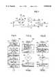
- FIG. 3is a schematic representation of the single-conduit embodiment of the present invention.
- FIG. 4is a schematic representation of the dual-conduit embodiment of FIG. 2;
- FIG. 5is an elevational view of the preferred vent valve element in position over the vent ends of the dual-conduit embodiment of FIG. 4;
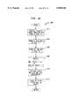
- FIGS. 6a, b and cpresents graphical illustrations of a typical breathing cycle including an inhalation phase and an exhalation phase, of the nasal air pressure imposed on the patient's airway during the breathing cycle, and of the vent valve steps required to maintain the set point pressures;
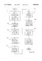
- FIG. 7is an electrical schematic illustration of the microcontroller and associated components of the present invention.
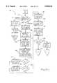
- FIG. 8is an electrical schematic of the blower motor control
- FIG. 9is an electrical schematic of the stepper motor control for the vent valve
- FIG. 10is a schematic illustration of a pressure transducer circuit
- FIG. 11is a computer program flowchart illustrating the START-UP portion of the main routine
- FIG. 12is a computer program flowchart of the MAIN LOOP portion of the main routine
- FIG. 13is a computer program flowchart of the VALVE STEP subroutine
- FIG. 14is a computer program flowchart of the ADC interrupt
- FIG. 15is a computer program flowchart of the CHECK BLOWER SPEED subroutine
- FIG. 16is an electrical block diagram illustrating the spectral sound analysis circuit
- FIG. 17is a computer program flowchart of the SOUND ANALYSIS subroutine
- FIG. 18is a schematic block diagram of another embodiment of the invention for determining patient airway patency
- FIG. 19is a set of five graphs of the embodiment of FIG. 18 illustrating airway flow, pressure and admittance, and further illustrating two admittance templates;
- FIG. 20is a computer program flowchart for operating the microcontroller of FIG. 18;
- FIG. 21is a computer program flowchart of another program embodiment for operating the microcontroller of FIG. 18;
- FIG. 22is a block diagram of the pneumatic components of the compensation embodiment of the present invention.
- FIG. 23is a block diagram of the electronic components associated with the compensation embodiment of FIG. 22;
- FIG. 24is a computer program flowchart of the PRIMARY module for operating the compensation embodiment
- FIG. 25is a computer program flowchart of the INITIALIZE module of the PRIMARY module
- FIG. 26is a computer program flowchart of the EXHALE module of the PRIMARY module
- FIG. 27is a computer program flowchart of the INHALE module of the PRIMARY module
- FIG. 28is a computer program flowchart of the CPAP BACKUP module of the PRIMARY module
- FIG. 29is a computer program flowchart of the BPM CYCLE BACKUP module of the PRIMARY module
- FIG. 30is a computer program flowchart of the PATIENT CYCLE BACKUP module of the PRIMARY module
- FIG. 31Ais a computer program flowchart of the first portion of the AID INTERRUPT module of the PRIMARY module.
- FIG. 31Bis a computer program flowchart of the remaining portion of the A/D INTERRUPT module.
- FIG. 3schematically illustrates the single conduit embodiment of the preferred inspiratory airway pressure apparatus 10 which broadly includes an elongated, flexible, hose or conduit 12, nasal pillow 14 connected to one end of conduit 12, vent valve assembly 16 positioned adjacent the opposed, open, vent end of conduit 12, blower unit 18 fluidically coupled with conduit 12 between pillow 14 and vent valve assembly 16, and controller 20 which is adapted for pneumatic connection with nasal pillow 14 and electrical connection with vent valve assembly 16 and blower unit 18.
- vent valve assembly 16, blower unit 18, and controller 20are housed within cabinet 22 such as that illustrated in FIG. 2 in connection with the dual-conduit embodiment.
- conduit 12presents an interior portion which is housed within cabinet 22 and exterior portion 26 which extends from the cabinet to nasal pillow 14.
- Conduit 12additionally presents coupling end 28 coupled to nasal pillow 14, inlet end 30 coupled with blower unit 18 for receiving a supply of breathable gas, preferably ambient air therefrom, and vent end 32 positioned adjacent vent valve assembly 16.
- Nasal pillow 14is the preferred patient-coupling device and is further illustrated in U.S. Pat. No. 4,782,832 which is hereby incorporated by reference.
- Head gear 34holds nasal pillow 14 on the head of patient 36 in order to fluidically couple with the respiratory passages of patient 36, and preferably with the patient's nares.
- Nasal pillow 14is configured to present pressure sensor fitting 38 which is coupled with controller 20 by pneumatic line 40 which is preferably routed within conduit 12 so that line 40 is conveniently out of the way and less likely to be pinched or restricted by the patient during use of apparatus 10.
- Nasal pillow 14also includes vent port 42 defined therethrough which continuously vents a small amount of pressure from nasal pillow 14 in order to prevent moisture buildup and subsequent condensation therein. Port 42 also prevents build up of exhaled gases including carbon dioxide.
- Vent valve assembly 16includes stepper motor 44 and valve element 46 connected to the output shaft thereof.
- Valve element 46is preferably constructed of a flat plate configured to present two, opposed, arcuate, cam-like edges 48a,b as illustrated in FIG. 5.
- Element 46is positioned adjacent vent end 32 of conduit 12 so that as stepper motor 44 rotates valve element 46 in a clockwise direction as viewed in FIG. 5, edge 48a progressively covers and thereby restricts vent end 32. Conversely, as motor 44 rotates element 46 in a counterclockwise direction, edge 48a progressively exposes an increasing area of vent end 32 to vent additionally gas therefrom.
- FIG. 4illustrates the dual-conduit second embodiment of preferred apparatus 10.
- Second embodiment 50additionally includes exhaust hose 52 presenting connection end 54 fluidically coupled to conduit exterior portion 26 at junction 56, and presents exhaust end 58 positioned adjacent valve element 46 in the same opening/closing relationship with arcuate edge 48b as vent end 32 presents to arcuate edge 48a.
- conduit 12additionally presents inhalation hose 60 between juncture 56 and blower unit 18.
- nasal pillow 14does not include vent hole 42, and the tube between ends 54 and 28 include divider 61 to separate it into two separate passages.
- Second embodiment 50may also include inhalation check valve 62 disposed within inhalation hose 60 adjacent juncture 56, and exhalation check valve 64 disposed within exhaust hose 52 also adjacent juncture 56.
- Inhalation check valve 62prevents passage of patient exhalation therethrough toward vent end 32 and thereby requires that the patient's exhalation exit the system through exhaust end 58.
- Pneumatic lines 66 and 68respectively couple controller 20 with inhalation hose 60 and exhaust hose 52.
- controller 20controls apparatus 10 in order to increase the gas pressure presented to the patient at a time in the patient's breathing cycle just prior to inhalation, and to subsequently lower the pressure for ease of exhalation.
- the upper graph of FIG. 6illustrates a typical breath cycle air flow.
- the flow rate of gas to the patientgradually increases to a maximum and then decreases.
- the patienttypically experiences a slight pause before exhalation begins.
- the exhaled gas flow from the patientgradually increases to a maximum and then decreases again.
- a post-exhalation pausetypically somewhat longer than the post-inhalation pause, follows exhalation. After the postexhalation pause, the patient again begins inhalation.
- the middle graph of FIG. 6illustrates the nasal airway pressure presented to patient 36 during operation of apparatus 10.
- this middle graphillustrates an increase in the nasal airway pressure just prior to inhalation to a selected prescription pressure level sufficient to push surrounding tissue aside and open this airway.
- the set point pressure presented to the nasal airwayis reduced so that exhalation occurs against a low or even zero pressure level relative to ambient.
- the nasal airway pressureis again increased prior to the next inhalation phase.
- blower unit 18in one embodiment of the invention, produces a generally constant volume per unit time of breathable gas which is selectively vented through vent end 32.
- the vented gas volumeis controlled by vent valve assembly 16.
- the bottom graph of FIG. 6graphically depicts the various positions of valve element 46 in relation to vent end 32 in order to achieve the desired nasal airway pressure profile illustrated in the middle graph.
- controller 20activates stepper motor 44 to rotate valve element 46 in a clockwise direction (as viewed in FIG. 5) in order to increase the nasal airway pressure to the desired set point as sensed by controller 20 by way of pneumatic line 40.
- gas output from blower unit 18is inhaled by the patient.
- the controllerthen rotates valve element 46 in stepwise fashion further in the clockwise direction to reduce the amount of gas being vented.
- controller 20begins to reverse the position of valve element 46 to vent additional gas for maintaining the set point pressure.
- controller 20continues, in stepwise fashion, to rotate valve element 46 in the counterclockwise direction to vent additional amounts of gas for achieving a new lower set point pressure.
- controller 20causes valve element 46 to further rotate in a clockwise direction to open vent end 32 even further.
- controller 20rotates valve element 46 in a clockwise direction to decrease venting in order to maintain the lower set point pressure.
- controller 20then causes valve element 46 to rotate further in the clockwise direction to increase the pressure to the higher pressure set point. This induces tension in the genioglossus muscle to open the airway in preparation for the next inhalation phase.
- controller 20is able to track a patients breathing cycle by tracking the stepped positions of valve element 46 required to maintain the set point pressures. In this way, controller 20 is able to determine the end of respective inhalation/exhalation phases and to predict exhalation and inhalation interval times.
- controller 20provides electrical outputs to control the speed of blower unit 18 and the position of stepper motor 44. Controller 20 receives electrical feedback from blower unit 18 indicative of the speed thereof, and a pneumatic input by way of pneumatic line 40 to indicate the pressure at nasal pillow 14 and thereby in the patient's nasal airway passages.
- Controller 20includes pressure transducer circuit 700 (FIG. 7) for providing an electrical input indicative of the pressure at nasal pillow 14 to microcontroller circuit 800 (FIG. 8) which in turn provides outputs to blower motor circuit 900 (FIG. 9) and stepper motor circuit 1000 (FIG. 10). Additionally, controller 20 includes a conventional 120 v.a.c. to +5 v.d.c., +12 v.d.c., and +24 v.d.c. power supply (not shown) suitable for digital and analog, solid state integrated circuit components.
- Pressure transducer circuit 700 illustrated in FIG. 7is typical of the pressure transducer circuit for both the single and dual conduit embodiments of the present invention. That is to say, the single conduit embodiment of FIG. 3 uses only one pressure transducer whereas the embodiment schematically illustrated in FIG. 4 uses two pressure transducers both using a circuit as illustrated in FIG. 7.
- the preferred pressure transducerincludes SENSYM type SX01DN having a zero-to 70-cm. water operational range.
- the preferred transducerincludes four strain gages arranged in a conventional Wheatstone bridge 701 having strain gages X1, X2, X3, and X4 presenting a nominal 4650 ohms each.
- Bridge 701presents excitation terminal 702 connected to +12 v.d.c. and an opposed excitation terminal 704 connected to ground as shown.
- Bridge 701produces outputs at terminals 706 and 708.
- Zero adjustment potentiometer 710interconnects terminals 704 and 706.
- the output from terminal 708is connected to the positive input terminal of operational amplifier 712 (one-half of Type LT1014).
- the output of operational amplifier 712provides feedback to the negative input terminal thereof, and, by way of resistor R1 (1K ohms) supplies the positive input terminal of amplifier 714.
- the outputis also connected to ground by way of resistor R2 (750K ohms).
- Strain gage bridge output terminal 706is connected to the positive input terminal of operational amplifier 716 (the other half of unit LT1014).
- the output from amplifier 716provides feedback to the negative input terminal thereof and is connected by way of resistor R3 (1K ohms) to the negative input terminal of amplifier 714.
- the output from amplifier 714provides feedback to the negative input terminal thereof by way of resistor R4 (750K ohms).
- the output from amplifier 714is also connected by way of resistor R5 to output terminal 718 which, by way of the circuitry just described, provides output between 0 and +5 v.d.c. corresponding to a pressure of 0 to 25 cm. water.
- a similar outputis provided at a corresponding terminal 720 if a second pressure transducer is used.
- two transducersprovide additional pressure information which allows more precise tracking of inhalation and exhalation gas flows of the patient, and thereby more precise breath cycle tracking.
- FIG. 8is an electrical schematic diagram of microcontroller circuit 800 which includes microcontroller 802 (Intel Type 8097BH), programmable array logic (PAL) (Type PC16L8), erasable, programmable, read-only-memory (EPROM) (Type 27256), address latch 808 (Type 74HC373), random access memory (RAM) (Type 6264P), input/output serial data interface (RS232 Type MAX232), prescription (RX) switch array 814, and input data latch 816.
- microcontroller 802Intel Type 8097BH
- PALprogrammable array logic
- EPROMerasable, programmable, read-only-memory
- EPROMerasable, programmable, read-only-memory
- EPROMerasable, programmable, read-only-memory
- address latch 808Type 74HC373
- RAMrandom access memory
- RS232 Type MAX232prescription
- RXprescription
- Microcontroller 802receives power (Vcc) at +5 v.d.c. at terminals VCC, VPD, BW, RDY, VPP, and VREF as shown. Ground is connected to terminals NMI, VSS, EA, and ANGND. Crystal 802 is coupled between terminals XTAL1 and XTAL2 as shown and to which respective grounded capacitors C1 and C2 (33 pF each) are respectively coupled for timing signals at 12 MHZ.
- Microcontroller 802receives a reset signal at terminal RESET from reset sub-circuit 820.
- poweris supplied through resistor RS (100K ohms) to grounded capacitor C3 (22 uF) and to the input terminals of SCHMITT trigger NAND gate 822.
- resistor RS100K ohms
- C322 uF
- SCHMITTtrigger NAND gate 822.
- the resultant input voltage to NAND 822is low, and its output is logic high.
- This logic high outputis supplied to output terminal 824 which provides a reset signal to blower motor circuit 900 as discussed further hereinbelow.
- the initially logic high output from NAND 822is inverted by invertor 826 to provide a logic low signal to microcontroller terminal RESET which holds microcontroller 802 in reset until the charge on capacitor C3 builds to the trigger level of NAND 822.
- Reset circuit 820also includes a normally open, reset switch 828 coupled across capacitor C3 which allows manual reset.
- Diode D1is coupled access resistor R5 to provide a discharge path for C5 in the event of power off.
- Microcontroller 802also receives a pressure transducer input at terminal ACH0 and also at ACH1 if a second transducer is used as in the dual-conduit embodiment.
- a pressure transducer input at terminal ACH0 and also at ACH1if a second transducer is used as in the dual-conduit embodiment.
- one side of capacitor C4(0.005 nF) is connected to terminal 718 along with the anode of diode D2 and the cathode of diode D3.
- the other side of capacitor C4 and the anode of diode D3are connected to ground as shown and the cathode of diode D2 is connected to a supply voltage Vcc.
- An identical circuitis provided for terminal 720 using diodes D4, D5 and capacitor C5.
- Microcontroller 802includes internal analog-to-digital converters (ADC) which receive the respective analog inputs at terminals ACH0 and ACH1 and convert these to digital form for internal use in microcontroller
- Microcontroller 802also receives an input at terminal HS1.0 which is a pulse signal from blower motor circuit 900 representative of the speed of blower unit 18, discussed further hereinbelow.
- Microcontroller 802also uses a common address/data bus 830 which interconnects microcontroller 802 for data and address information flow with PAL 804, EPROM 806, address latch 808, RAM 810, and data latch 816 at the terminals as shown in FIG. 8.
- FIG. 8also illustrates the other conventional interconnections between these components as shown.
- Microcontroller 802provides a serial data output from terminal TXD to terminal 11 of interface 812 and receives data from terminal 12 thereof at microcontroller terminal RXD.
- Interface terminals 14 and 13receive RS232 data in and out which enable remote reading and control of microcontroller 802 and thereby apparatus 10. This feature is particularly useful in a sleep laboratory, for example, for adjusting the prescription pressures in order to achieve the optimal therapy.
- Switch array 814includes eight, selectable switches for providing input data representative of the desired prescription set point pressures for inhalation and exhalation.
- the top four switchesare used to set the prescription inhalation pressure and the bottom four switches for prescription exhalation pressure. With four switches for each set point, sixteen possible settings are available ranging between 3 and 16 cm water for inhalation, and 0 and 14 cm water for exhalation.
- Data latch 816is coupled with switch array 814 as shown and latches the prescription data upon receipt of the latch signal from terminal 12 of PAL 804. The prescription data is transmitted over bus 830.
- Microcontroller 802also provides two additional outputs. The first of these is data to stepper motor circuit 1000 by way of six-line output bus 832 from microcontroller terminals P1.0-1.5 to output terminal 834. The second additional output is a pulse-width modulated signal (PWM) to blower motor circuit 900 by way of line 834 and output terminal 836.
- PWMpulse-width modulated signal
- FIG. 9is an electrical schematic diagram representing blower motor circuit 900 which receives the pulse width modulated signal at terminal 836 from microcontroller 802, and also receives an inverted reset signal at terminal 824 from reset circuit 820. Blower motor circuit 900 also provides a pulse output signal at terminal 902 representative of the speed of blower motor 904 to microcontroller 802.
- the reset signal received at terminal 824is connected to terminal 10 of motor driver 906 (Type UC3524A).
- the pulse width modulated signal from controller 802 at terminal 836is provided to terminal 2 of driver 906 by way of low pass filter C6 (1.0 uF) and resister R7 (24.9K ohms).
- Driver terminal 7is connected to ground by way of capacitor C7 (0.003 uF), and terminal 6 is connected to ground by way of resistor R8 (49.9K ohms). Terminal 8 is connected to ground and terminal 15 receives power supply at +12 v.d.c. Driver terminal 12, 13, and 16 are connected to Vcc at +5 v.d.c.
- Motor driver 906converts the input pulse-width modulated signal at 0-5 v.d.c. to a corresponding output at 0 to +12 v.d.c. at terminals 11 and 14 thereof to programmable array logic (PAL) (Type 16L8) terminal 1. These terminals are also connected to ground by way of resistor R9 (0.5 ohms).
- PAL 908produces respective outputs at terminals 19 and 18 as two phases for the stator and rotor of brushless D.C. blower motor 904 (Fasco Corp. Type 70000-S517).
- the PAL 908 outputsare respective inputs to level converters 910 and 912 (MC14504) which shift the voltage level from +5 to +12 v.d.c.
- the +12 v.d.c. outputs from level converters 910 and 912are in turn transmitted to the respective gates of field effect transistors (SENSFET) (Motorola SENSFET Type MTP40N06M) 914 and 916.
- SENSFETfield effect transistors
- the respective drain terminals of SENSFETS 914 and 916are respectively connected to terminals 0A and 0B of blower motor 904 and provide the respective phase inputs to the stator and rotor thereof.
- Power at +12 v.d.c.is additionally provided to level converters 910 and 912 and to common power terminal CP of blower motor 904.
- each SENSFET 914, 916is connected to ground as shown.
- SENSFETS 914,916each include an additional pair of outputs on lines 918 and 920 which provide a sampling of the current flow through the respective SENSFETS. These outputs are coupled across resistor R10 (100 ohms) to provide a current path for the current sample, and thereby a voltage representative thereof to terminals 3 and 4 of motor driver 906.
- Driver 906is responsive to this input voltage representative of the current flow through blower motor 904 to reduce the duty cycle of the output at terminals 11 and 14 in the event of motor overcurrent.
- Blower motor 904is additionally equipped with Hall effect transducer which is operable to provide a voltage pulse each time a magnetic pole of the motor stator passes thereby. These output pulses represent the speed of motor 904 and are provided at motor terminal HALL by way of line 922 to output terminal 902, and as feedback to motor driver 906. The output pulses representative of motor blower speed at terminal 902 are provided to microcontroller 802 at terminal HS1.0 thereof.
- the pulses representative of motor blower speedare converted to a representative voltage before input to motor driver terminals 1 and 9.
- line 922is connected to one side of capacitor C8 (0.01 uF) the other side of which is connected to one side of resistor R11 (10K ohms), and to the anode of diode D6.
- resistor R11(10K ohms)
- the other side of resistor R11is connected to ground.
- the cathode of diode D6is connected to one side of grounded capacitor C9 (0.1 uF), to grounded resistor R12 (1M ohms) and to one side of resistor R13 (100K ohms).
- the other side of resistor R13is connected to one side of capacitor C10 (0.22 uF), to one side of resistor R14 (10M ohms), and to motor driver terminal 1 as input thereto.
- the other side of capacitor C10 and resistor R14are connected to driver terminal 9.
- This network of components C8-C10, R11-R14, and diode D6convert the frequency pulses on line 922 to a voltage representative thereof. That is to say, this network acts as a frequency-to-voltage converter owing to the large capacitance of capacitor C9 (0.1 uF) which provides a long time constant.
- the voltage value provided at motor driver terminals 1 and 9provides feedback to an internal comparator which compares the voltage to a set point derived from the pulse width modulated signal received at terminal 2.
- FIG. 10illustrates stepper motor circuit 1000 which activates stepper motor 44 to position valve element 46 in accordance with data received from microcontroller 802 at terminal 834 therefrom.
- Stepper motor 44is preferably a VEXTA model available from Oriental Motor Company and is capable of providing one revolution in 400 "steps" and is also capable of half-stepping if needed.
- motor 44is operable to shift one step upon the imposition of the next sequential voltage step pattern provided as input at terminal 834 over output bus 832.
- bus 832includes six lines, which are pattern data for the driver chip.
- step pattern datais provided to step motor driver chip 1002 (Type S'GS' L298N) at terminals A, B, C, and D respectively from terminals P1.0-1.3 of microcontroller 802.
- Driver 1002shifts the input data voltage from +5 v.d.c. to +12 v.d.c. for corresponding output at terminals 2, 3, 13, and 14 which are connected to stepper motor 44 to impose the step pattern thereon at +12 v.d.c.
- the anodes of diodes D7, 8, 9, and 10are connected to the respective four output lines of driver 1002, and the cathodes thereof are connected to +12 v.d.c. for voltage pull-up.
- the cathodes of diodes D11, 12, 13, and 14are connected respectively to the output lines, and the respective diode cathodes connected to ground as shown for voltage pull-down.
- +5 v.d.c.is provided at driver terminal 9, +12 v.d.c. at driver terminal 4, and terminals 1, 8, and 15 are all connected to ground.
- FIGS. 11-14are computer program flowcharts illustrating the operative program for microcontroller 802.
- FIG. 11illustrates the START-UP portion of the main routine of the computer program for operating microcontroller 802.
- the programenters at step 1102 which prompts controller 20 to shift vent valve assembly 16 to its "home" position.
- this stepprompts microcontroller 802 to produce data of sequential pattern outputs by way of line 832 and terminal 834 to stepper motor control circuit 1000.
- stepper motor 44This shifts stepper motor 44 to a mid-range position wherein valve element 46 blocks conduit ends 32 and 58 about half-way as shown in FIG. 5, or conduit end 32 alone in the single conduit embodiment.
- Step 1102also initializes the variables, counters, interrupt routines, and so forth in the program.
- step 1104to read the inhalation and exhalation prescription pressure values as set on switch array 814 and read by way of address data bus 830. These values are then stored in RAM. Step 1104 also prompts microcontroller 802 to set the operating speed of blower motor 904 in accordance with the prescription of pressure set on switch 814. The blower speed should be set at a level fast enough to ensure that sufficient ambient air volume is provided to conduit 12 such that the prescription pressure level can be attained during maximum inhalation. Blower motor speed data corresponding to prescription settings are stored preferably in a look-up table. Step 1104 also clears any value stored in the internal buffer at microcontroller terminal HS1.0.
- step 1106enables the program's timed interrupts to begin timing.
- step 1108the program sets the software flag "phase” equal to inhalation "I" which initializes the program from the inhalation phase of the patient's breathing cycle. This step also initializes the blower check counter at zero. As discussed further hereinbelow, the program reads the blower speed after 128 passes through the main loop.
- step 1110which starts the internal analog-to-digital converter (ADC) connected to microcontroller input terminals ACH0 and ACH1.
- ADCanalog-to-digital converter
- Step 1112sets the pressure set point for the inhalation phase according to the inhalation prescription value set on switch array 814 according to data in a look-up table.
- This stepalso defines the start-up mode of the apparatus as continuous positive airway pressure (CPAP). That is to say, and as explained further hereinbelow, the program operates apparatus 10 in order to present a continuous positive pressure at the inhalation set point pressure for the first eight breaths of a patient.
- Step 1112also initializes the breath counter at zero in preparation for counting patient breathing cycles.
- Step 1202is the first step of this routine in which the program calculates the average pressure as sensed by pressure transducer 701 over eight ADC conversions. That is to say, microcontroller 802 includes an internal "ring" buffer which stores the eight most recent pressure readings received at microcontroller terminal ACH0 (and also ACH1 in the two-conduit embodiment). As discussed further hereinbelow, ADC interrupt routine converts the input analog values to digital form every 22 microseconds and continuously stores the most recent digital values in the ring buffer. Step 1020 calculates the average value by dividing the cumulative buffer value by eight. Step 1202 also calculates the deviation, that is, error, in the average pressure from the pressure set point.
- step 1204which asks whether the magnitude of the error calculated in step 1202 is greater than allowed maximum error. This provides a so-called “dead band” to prevent the system from "hunting".
- step 1204the program moves to step 1206 and calculates the number of steps and direction of stepper motor 44 required to correct the pressure deviation error. That is to say, depending upon the volume of air being produced by the blower, the fluid capacity of the system, and the leakage therefrom, the number of required steps can be determined approximately by reference to data previously stored in a look-up table.
- VALVE STEP routine 1300sequentially presents the data patterns required to step the valve for the required number of steps in the direction determined in step 1206.
- step 1210stores the number of valve steps and direction actually implemented in an internal valve slope buffer which continuously stores the previous eight movements of stepper motor 44.
- the slope of valve movementcan be calculated by dividing the valve slope buffer sum by eight. This represents a slope because the eight values are stored at equal time intervals and thus the buffer sum divided by eight represents the first derivative of value movement.
- step 1212which asks whether the phase flag is set for exhalation.
- the programwas initialized with the phase flag set for inhalation, and so, during the first few passes through main loop 1200, the answer in 1212 is no and the program moves to step 1214 which asks whether the phase flag is set for inhalation. Because this flag is initialized as inhalation, the answer in step 1214 is yes and the program moves to step 1216.
- Step 1216asks whether the variable "timer counter” is greater than the value for variable "inhalation end time", and whether the slope as calculated in step 1210 is less than or equal to -5.
- the variable "timer counter”(TMR CNT) is a software counter which was initialized at zero and increments every 13 milliseconds.
- the variable "inhalation end time”was initialized at a default value representing inhalation time equivalent to a predetermined average value. As discussed further hereinbelow, the variable “inhalation end time” is recalculated for each breath cycle after an initial eight passes through main loop 1200.
- Step 1216operates to determine whether sufficient time has passed for normal inhalation to be complete as additionally confirmed by the value slope being less than -5 as illustrated by the slope of the value position curve at the end of inhalation in FIG. 6.
- step 1216During the first few passes through main loop 1200, the answer in step 1216 is no and the program moves to step 1218 which asks whether the blower check counter, initialized at zero, is equal to 128. Until then, the answer in step 1218 is no and the program moves to step 1220 to increment the blower check counter.
- the programthen loops back to step 1202 and repetitively executes steps 1202-1220 until the answer in step 1218 is yes whereupon the program moves to step 1222 to execute the sub-routine "CHECK BLOWER SPEED" 1200 as illustrated in FIG. 15. As discussed further hereinbelow, this step monitors the blower speed to ensure that it is running at the set point speed initially set in step 1104 in accordance with prescription settings. The program then returns to step 1224 to reset the blower check counter at zero.
- step 1216After sufficient time has elapsed to exceed the default time set for the inhalation end time, and when the slope of the valve position curve is equal to or less than -5 indicating the end of patient inhalation, the answer in step 1216 is yes and the program moves to step 1218 which asks whether the mode of operation is set for inspiratory nasal air pressure (INAP).
- INAPinspiratory nasal air pressure
- step 1232sets the variable "cycle time” equal to the current value existing on the timer counter. This step is entered at the end of each inhalation phase and marks the end of one breath cycle and the beginning of another. Thus, the time of one breath cycle, that is, cycle time, equals the time value existing on the timer counter which is reset to zero at the end of each breath cycle, also in step 1232.
- Step 1232also sets a new inhalation interval time equal to the new cycle time divided by three. Statistically, inhalation time averages about 40% of a typical breathing cycle. Step 1232, however, sets the inhalation interval equal to 33% of the most recent cycle time in order to ensure that this value clocks out in step 1216 early, that is, before the end of anticipated actual inhalation time.
- Step 1232also sets the variable "inhalation start time" equal to the new cycle time divided by two. With the beginning of a cycle marked as the end of an inhalation phase, the next inhalation start time would normally be expected to occur after 60% of the cycle time has elapsed. Step 1232, however, sets inhalation start time at 50%, that is earlier than the predicted inhalation time in order to ensure an increase in nasal pressure before inhalation would be expected to begin.
- step 1228After main loop 1200 has detected eight breath cycles as indicated on the breath counter, the answer in step 1228 is no and the program moves to step 1234 which sets the operating mode as INAP.
- the eight cycle delay in setting the INAP modeensures reliable data in tracking the breath cycle.
- step 1226With the mode now set as INAP, the answer during the next pass at step 1226 is yes and the program moves to step 1236 to set the pressure set point equal to the exhaust prescription. That is to say, an inhalation phase has ended as determined in step 1216, eight breaths have been tracked as determined in step 1228, the mode is set as INAP which allows a decrease in pressure during exhalation. With these conditions satisfied, the controlled pressure set point is lowered to the prescribed exhaust prescription set point.
- the exhaust pressurewould be prescribed at zero, that is ambient, so that the patient can exhale normally. In some circumstances, however, the therapist may desire a slight positive pressure during exhalation which is set on the lower four switches of switch array 814 (FIG. 8).
- Step 1236also sets the phase flag for exhalation.
- step 1238asks whether the current value on the timer counter is greater than or equal to the inhalation start time as previously set in step 1232.
- step 1238asks whether the valve position slope is greater than seven which independently indicates the end of exhalation.
- the valvemust step in the positive direction rapidly in order to restrict vent end 32 for maintaining the set point pressure. This rapid change indicates a positive slope greater than 70.
- step 1238If the answer in step 1238 is no, the program continues to loop through until the answer is yes at which time the program moves to step 1240 to set the phase flag for inhalation, to set the pressure set point at the inhalation prescription value, and to set the value for the variable "inhalation end time" equal to the currently existing timer count plus the inhalation interval time.
- the existing value of the timer countercorresponds to the time elapsed since the beginning of the current breath cycle, which marked the end of the previous inhalation phase.
- the inhalation phase about to beginshould end on or after the current timer count value plus the inhalation interval time.
- step 1240provides a new value for inhalation interval time for use in step 1216.
- step 1216for both the expiration of the inhalation end time and a slope less than or equal to -5.
- step 1238in cooperation with the balance of the operating program, ensures that the inhalation set point pressure increases before the onset of patient inhalation.
- the end of exhalationcan be detected. Marking the end of an exhalation phase ensures that this is a point in the breath cycle prior to the beginning of the next inhalation phase. Additionally, an increase in the pressure prior to inhalation is assured by monitoring whether the timer counter is greater than or equal to the predicted inhalation start time in step 1238.
- FIG. 13illustrates VALVE STEP sub-routine 1300 which operates to impose sequentially the required step patterns on stepper motor 44 by way of stepper motor circuit 1000.
- Sub-routine 1300enters at step 1302 by setting the variable "final valve position” equal to the current valve position plus (or minus) the valve correction required as determined in step 1206 (FIG. 2).
- Step 1302also sets the variable "valve position” equal to the current valve position.
- step 1304which asks whether the correction direction is greater than zero, that is, in a positive direction to restrict vent end 32, or in the opposite direction. If the answer in step 1304 is yes, the program moves to step 1306 which asks whether the final position as determined in step 1302 exceeds step 160. That is to say, this step determines whether the requested or desired final valve position is beyond the maximum allowed position. It yes, the program moves to step 1308 which sets the final valve position equal to 160.
- step 1310the program moves to step 1310 to set the variable "valve position" equal to "valve position" plus one. In other words, the program increments stepper motor 44 one step at a time until the final position is achieved.
- step 1312which asks whether the new valve position is less than or equal to the final valve position as determined in step 1302. If no, which indicates that the desired final valve position has been achieved, the program returns to main loop step 1210.
- step 1312If the answer in step 1312 is yes, indicating that the final valve position has not yet been achieved the program moves to step 1314 which retrieves the step pattern for the next blower motor step from memory. The program then activates the lines of bus 832 in order to send this step pattern to stepper motor circuit 1000 and thereby to stepper motor 34.
- the programthen loops back to step 1310 to continue executing step patterns one at a time in sequence until the final position is obtained.
- step 1304If the rotational direction for correction requires is negative as determined in step 1304, the program moves to steps 1316-1324 as illustrated to execute the required number of stepping patterns to shift the valve in the "negative" direction to reduce pressure by venting more air.
- Step 1316asks whether the final position determined in step 1302 is less than zero indicating a valve position beyond the allowable limits of travel. If yes, the program sets the final position equal to zero in step 1318.
- Step 1320then decrements the "valve position" variable and step 1322 asks whether the newly determined “valve position" is greater than or equal to the final position desired. If yes, the step moves to program 1324 and then loops back to step 1322. If the answer is step 1322 is no, the program returns to main loop step 1210.
- FIG. 14illustrates ADC interrupt sub-routine 1400 which has its interrupt executed every 14 micro-seconds for providing an analog-to-digital conversion for the pressure data received from pressure transducer circuit 700, and to store this data in memory.
- Subroutine 1400enters at step 1402 which retrieves the current data from the ADC register internal to microcontroller 802. This data is then stored in the ADC buffer for use in step 1202 (FIG. 12) of the main loop. This data is stored at location "L" which is one of the eight buffer locations. The program then moves to step 1404 to increment location variable "L" so that the next set of ADC data is placed in the next buffer location.
- step 1406which asks whether "L" is equal to eight which is greater than the number of locations provided in the ADC buffer. If yes, the program resets "L" at location zero which is the first location in the buffer. After step 1408, or if the answer in step 1406 is no, the program moves to step 1410 which instructs the ADC to begin another data conversion. The program then returns from the interrupt to the main loop.
- FIG. 15illustrates CHECK BLOWER SPEED subroutine 1500 which is entered from step 1222 of main loop 1200, and enters at step 1502 which reads the current blower speed as received at microcontroller terminal HS1.0 from the Hall effect transducer in blower motor 94.
- the programthen moves to step 1504 which retrieves the blower speed set point corresponding to the prescription inhalation pressure and compares the set point to the sensed lower speed.
- the programthen moves to step 1506 which asks whether the blower speed is within a maximum error range of the set point speed. If no, the program adjusts, in step 1508, the pulse-width of the pulse width modulated signal produced at microcontroller terminal PWM and transmitted to blower motor circuit 900. After step 1508, or if the answer in step 1506 is yes, the program returns to the main loop.
- FIGS. 16 and 17illustrate another aspect of the invention in which patient airway pressure variations and, in particular, airway sounds are monitored and the patient airway pressure controlled in response.
- FIG. 16is an electrical block diagram illustrating sound analysis circuit 1600 which receives input from pressure sensor circuit 700 by way of terminal 718 thereof, and which delivers outputs to microcontroller 802.
- soundsare pressure variations and as such, preferred pressure sensor circuit 700 is also operable for sensing pressure variations representative of airway sounds and in converting these variations into representative signals at terminal 718.
- the signals from pressure sensor circuit 700are delivered to preamplifier 1602 which boosts the signal level for delivery to low-pass filter 1604, band-pass filter 1606, band-pass filter 1608, and high pass filter 1610.
- Low-pass filter 1604is included to provide output "DC" to microcontroller 802 indicative of low frequency (subaudio) pressure variations and nasal pressure.
- Filters 1606-10split the audio frequency spectrum into three components: 10-200 Hz., 200-800 Hz., and 800+ Hz. respectively.
- the outputs from filters 1606-10pass through respective rectifiers 1612, 1614, and 1616 which in turn provide rectified outputs to low-pass filters 1618, 1620, and 1622.
- Low-pass filters 1618-22convert the respective rectified inputs to equivalent D.C. voltage outputs "LOW”, "MED”, and "Hi” which represent the respective audio spectral components.
- These three outputs along with output "DC”are provided as inputs to microcontroller 802 which uses internal analog-to-digital conversion to produce digital data representative of the three spectrum components.
- FIG. 17is a computer program flowchart of SOUND ANALYSIS subroutine 1700 which is advantageously included as part of the program for operating the microcontroller 802 in connection with the pressure variation aspect of the invention.
- Subroutine 1700enters at step 1702 which initiates analog-to-digital conversion of the analog inputs "DC", "LOW”, “MED”, “Hi” received from circuit 1600.
- step 1702is implemented a number of times (for example, ten times) for each inhalation and the conversion values averaged. The average values of the digital representations of DC, LOW, MED and Hi are then used for steps 1706-1716 as discussed further hereinbelow.
- step 1704sets the software variable "old state” (OS) equal to the variable “new state” (NS) determined in the previous passes through the program. This step then sets variable NS equal to zero.
- step 1706the program asks whether input "DC" is greater than a predetermined threshold value. This threshold value is set at a level sufficient to indicate that detectable airway sounds are occurring. If the answer is no, the program returns to the main loop. If yes, the program moves to 1708 in which, along with subsequent steps, conducts a spectral analysis of the airway sounds as determined by circuit 1600. In particular, step 1708 asks whether input LOW is of a predetermined threshold. If yes, the program moves to step 1710 which increments variable NS by 1.
- step 1710If the answer in 1710 is no, or after step 1710, the program moves to step 1712 which asks whether input MED is above its associated threshold. If yes, the program moves to step 1714 which increments variable NS by 2.
- step 1712If the answer in step 1712 is no, or after step 1714, the program moves to step 1716 which asks whether input Hi is greater than its predetermined threshold. If yes, then step 1718 increments variable NS by 4.
- Step 1720calculates the variable "transition" (T) as a function of variables OS and NS as shown in FIG. 17.
- Tis a spectral quantification of the airway sounds for use in determining which action, if any, should be taken concerning the increase or decrease of the gas pressure applied to the respiratory passages of the patient.
- This determinationoccurs in step 1722 by use of a so-called "action table” which is a look-up table stored in memory using variable T as a pointer.
- the preferred action tableis incorporated as part of the disclosure hereof as Appendix I attached hereto.
- step 1724Upon determining the proper action including increase, decrease, or maintain pressure from the action table, the program moves to step 1724 which executes that action.
- action-designated changes in pressureare in increments of 1.0 cm. water pressure.
- step 1724If the action determined in step 1722 is "none", which indicates that snoring sounds are not occurring, it is preferred in step 1724 that the patient-applied the pressure be decreased by 0.5 cm. water. In this way, the program assures-that the pressure is not maintained at a level greater than that necessary. For example, if the detected airway sounds prompts an increase in pressure, and the airway sounds then disappear, it may be that the pressure was increased slightly more than necessary. Accordingly, the program will automatically decrease the pressure over time in small increments until airway sounds are again detected.
- pressure transducer circuit 700is sensitive to many types of pressure variations other than those associated with airway sounds.
- circuit 700could be used to detect inaudible vibrations or pressure variations associated with exhalation and inhalation.
- much informationcan be garnered about a patient's respiration such as whether the patient's respiration is rhythmic, erratic, or apneic as well as breath rate, inhalation and exhalation durations, and flow rates.
- the patient's respirationcan be properly characterized and aspects of the respiration quantified.
- this informationcan be stored in memory for subsequent downloading for use by a physician, for example, in diagnosing respiratory afflictions and efficacy of treatment.
- a physicianfor example, in diagnosing respiratory afflictions and efficacy of treatment.
- patient comfortis enhanced because only the minimum required pressure is imposed both during sleep and before the patient falls to sleep. With increased comfort, the patient is more likely to use the prescribed treatment on a sustained basis and thereby gain the maximum benefit therefrom.
- the present inventionencompasses many variations in the preferred embodiments described herein.
- the present inventionis useful in treating sleep apnea, its utility is not so limited, but rather, the present invention is useful in treating many conditions in which facilitated respiration is a factor in treatment. For example, increased respiratory air pressure beginning just prior to inhalation induces a deeper inhalation than might otherwise occur. This may be useful in treating certain cardiovascular conditions where deeper inhalation and thereby greater oxygenation of the blood is beneficial when accompanied by decreased pressure to ease exhalation.
- the present inventionencompasses the use of any breathable gas such as anesthesia or oxygen-supplemented ambient air.
- the nasal pillowis the preferred means for patient coupling in order to impose the higher breathable gas pressure on the respiratory passages of the patient.
- the present inventionalso encompasses a nasal mask, or a full face mask which may be desired in certain situations such as the application of anesthesia as breathable gas as discussed above.
- the position of the vent valve assemblyis varied in order to increase or decrease the pressure of the breathable gas applied to the patient's respiratory passages.
- the apparatus hereofincludes the capability of varying the speed of the blower unit which could be used instead to selectively vary the applied pressure. This would eliminate the need for the vent valve and stepper motor and reduce the manufacturing cost which would be advantageous as another embodiment of the invention.
- the present inventionalso encompasses the variation wherein the breathable gas is compressed and stored in a storage bottle, for example.
- the preferred controllerincludes microcontroller 802 which is operated by a computer program.
- Other equivalent control meansmight include a custom designed chip with all functions implemented in hardware without a computer program.
- vent valve assembly 16it is preferred to track the patient's breathing cycle by tracking the movement of vent valve assembly 16.
- breath cyclecan be tracked by other means such as monitoring chest contractions and expansion, breathing sounds, directly sensing genioglossus muscle activity, or some equivalent parameter indicative of a breathing cycle.
- some therapistsmay prefer that the apparatus start up in a low pressure or zero pressure mode while the breath cycle is initially tracked. This may provide further patient comfort in the use of the invention.
- FIGS. 18-21illustrate another embodiment of the present invention in which patient airway patency is determined and preferably used as the basis for controlling airway pressure applied to the patient.
- apparatus 1800includes flow sensor 1802 (Hans Rudolph Pneumotach available from the Hans Rudolph Company of Kansas City, Mo.), differential pressure (DP) sensor 1804 (SENSYM type SX01DN), pressure sensor 1806 (SENSYM type SX01DN), operational amplifiers 1808 and 1810, analog signal divider 1812 (Analog Devices model AD539) operably coupled with microcontroller 802.
- flow sensor 1802Heans Rudolph Pneumotach available from the Hans Rudolph Company of Kansas City, Mo.
- DPdifferential pressure
- DPpressure sensor 1804
- pressure sensor 1806SENSYM type SX01DN
- operational amplifiers 1808 and 1810operational amplifiers 1808 and 1810
- analog signal divider 1812Analog Devices model AD539
- flow sensor 1802is preferably coupled in exterior portion 26 of conduit 12 so that breathable gas supplied to the patient passes therethrough.
- Sensor 1802provides a pair of pneumatic output signals representative of the gas flow to DP sensor 1804 which in turn provides a pair of output electrical analog signals from the internal bridge representative of the flow to amplifier 1810.
- Pressure sensor 1806is pneumatically coupled with exterior portion 26 preferably downstream from flow sensor 1802. Pressure sensor 1806 provides a pair of signals from the internal bridge to amplifier 1808 representative of the gas pressure being supplied to the patient.
- Amplifiers 1808 and 1810provide respective analog output signals representative of the instantaneous-gas pressure and flow being supplied to the patient by way of lines 1814 and 1816 to divider 1812.
- Divider 1812performs an analog division of the flow and pressure signals presented on lines 1814,1816 and thereby produces an analog output signal on line 1818 representative of the instantaneous admittance (A) of the patient's airway. That is to say, admittance is the inverse of impedance, but patient flow can be zero which prevents direct calculation of impedance as pressure divided by flow. However, by dividing flow by pressure, and thereby determining admittance, such problems are avoided.
- divider 1812in certain applications and perform the division functions within microcontroller 802. If such is the case, line 1818 along with divider 1812 are eliminated, and the pressure and flow signals on lines 1814, 1816 are provided directly to microcontroller 802.
- FIG. 19includes graphs 1902, 1904, 1906, 1908, and 1910 which aid in illustrating how patient airway patency is determined in the present invention. These graphs respectively plot flow F, pressure P, admittance A, template T1, and template T2 versus seven discrete times corresponding to those times when microcontroller 802 performs analog-to-digital conversions of the input information.
- the plot of admittance in graph 1906is a function of the flow and pressure data illustrated in graphs 1902, 1904 respectively.
- the admittance plot for the inhalation portion of a single breath cycleis compared to admittance templates stored in memory to determine which template provides the "best fit" with the latest admittance plot.
- the best fitis determined by using conventional root-mean-square techniques.
- the template which fits bestis used as a "pointer" for a look-up table to select action to be taken such as raising or lowering gas pressure delivered to the patient.
- FIG. 20illustrates a computer program flowchart of subroutine 2000 for operating microcontroller 802 of the embodiment shown in FIG. 18 using divider 1812.
- Routine 2000enters at step 2002 which activates microcontroller 802 to digitize the admittance signal received on line 1818 at the predetermined times during patient inhalation and to store the converted admittance data in data array "A.”
- step 2004then normalizes the amplitudes of the amplitude data in array "A.” That is to say, the peak-to-peak amplitude value of the array data is normalized to a predetermined constant. This is done because, in the preferred embodiment, the shape of the admittance data is of interest, not the absolute values.
- step 2006normalizes the time base of the admittance data array "A" so that the time base matches that of the templates. This is needed because inhalation times vary from breathe to breathe.
- step 2008which computes a root-mean-square (RMS) value for the differences between the corresponding data points in array "A" and each template stored in memory according to the formula shown.
- RMSroot-mean-square
- step 2010determines which template presents the lowest RMS value, this being the template that "best fits” the admittance data for that inhalation of the patient.
- Step 2012uses the template selected in step 2010 as a software "pointer" to select an appropriate action, such as increase, decrease or maintain pressure, from a look-up table such as that illustrated below:
- FIG. 21is a computer program flowchart of module 2100 for operating microcontroller 802 in the embodiment of FIG. 18 when divider 1812 and line 1818 are not used, and when lines 1814, 1816 are connected directly to microcontroller 802 for providing the pressure and flow signals. This variation is advantageous when greater precision is desired because of the non-linear characteristics of patient airways.
- Module 2100enters at step 2102 which digitizes the flow signals received by microcontroller 802 by way of line 1816 at the predetermined interval times. The digitized flow data is then stored in array "F”. Step 2104 then normalizes the time base of the data in array "F.”
- step 2106uses Fast Fourier Transform (FFT) to convert the amplitude vs time data in array "F" to amplitude vs frequency data.
- FFTFast Fourier Transform
- module 2100executes analogous steps 2108, 2110 and 2112 for the pressure information received by microcontroller 802 over line 1814.
- step 2114computes admittance "A" for each corresponding flow and pressure data points.
- admittance "A"For each corresponding flow and pressure data points.
- Module 2100then executes 2116, 2118 and 2120 which are the same as steps 2008-2012 discussed above in connection with module 2000 and the action table.
- the set of templates stored in memorycould represent a range of patencies (in percentages, for example) and the best-fit template represents a corresponding patency as a percentage.
- the patency templatesare preferably a set custom-developed for the particular patient being treated.
- it may be advantageous to continuously update the set of templatesby storing successive admittance array data in memory as a new template.
- certain templatescould be designated as templates characteristic of wakefulness or sleep states.
- a summation of the admittance data of a given inhalation, or an average thereof over a number of inhalationscould be used itself as a quantification of airway patency.
- ultrasound techniquescould be used to establish airway patency.
- gas pressure applied to the patientis relatively constant, only flow variations are of interest and are the only variable parameter which may be considered.
- a sensitive thermocouple or thermistorcould be used as an indication of gas flow.
- the spectral sounds embodiment of the present inventionanalyze the patient airway sounds to determine an appropriate response for preventing an apneic episode.
- the appropriate actionincreases, decreases or maintains the airway pressure applied to the patient.
- the preferred responseis the application of electrical stimulus externally applied to the neck of the patient in the vicinity of the upper airway muscles, although implanted electrodes would be used equivalently to stimulate the muscles or the muscle nerves.
- the preferred apparatusincludes a flexible, elastic neck collar, a microphone carried by the collar, a pair of electrodes also carried by the collar, and control circuitry interconnecting the microphone and the electrodes.
- the electrodes and microphonecould also be affixed by adhesive or other equivalent means instead of the preferred collar.
- the preferred control circuitryincludes the components and program described above in connection with the airway sounds embodiment. The primary difference being that instead of increasing air pressure, the action is to activate the stimulating electrodes at the beginning of each inhalation phase of the patient breath cycle.
- the patientcouples the collar about the neck with the electrodes positioned in front about either side of the neck centerline and just underneath the jaw in order to stimulate the upper airway muscles when activated.
- the microphonedetects airway sounds and the control circuitry analyzes these sounds as described above in connection with FIGS. 16 and 17. Whenever an action is determined corresponding to "increase" pressure (FIG. 17, Step 1724), this is interpreted as imminence of an apneic event. That is to say, gradual closing of the airway due to relaxation of the upper airway muscles produces sound patterns indicative thereof which also indicates, that is, predicts that an apneic episode may occur on a subsequent breath.
- the control circuitryactivates the electrodes to stimulate the upper airway muscles. Additionally, it is preferred to vary the strength of the electrical stimulation according to the breath sounds in the same manner that airway pressure is varied in connection with the admittance embodiment discussed above in connection with Appendix I. In the event that inhalation is not detected for a predetermined time based upon a fixed time or based upon previous breathing patterns the preferred breathing device activates the electrodes to stimulate the upper airway muscles.
- an apneic episodecan be predicted and stimulation applied when this occurs. That is to say, by monitoring admittance during inhalation, a narrowing of the airway can be detected by monitoring the admittance, and when admittance decreases to a predetermined level, stimulation can be applied.
- the imminence of an apneic episodecould be determined by using airflow sensors such as thermistors or thermocouples at the nose or mouth, or a static-charge sensitive "bed", or bands for sensing chest or abdomen movement preferably a RESPITRACE brand sensor.
- FIGS. 1-4uses pressure sensor 38 mounted adjacent the patient nasal fitting. In some circumstances, however, this may not be practical. Instead, for compactness and economy of manufacture, it may be desirable to use pressure and flow sensors coupled with the patient pneumatic line at the point where this line leaves cabinet 22. This arrangement, however, may allow inaccuracies in measurement to occur because of downstream pneumatic leaks and pressure drops in the line which vary nonlinearly with flow to the patient. In addition to unintended leaks, it is preferable to have a vent at the patient's nasal connection to prevent buildup of carbon dioxide. Thus, flow and pressure as measured at the cabinet outlet may not provide accurate data concerning the actual pressure delivered at the patient's nose.
- the compensation embodiment of the present inventionmeasures pressure and flow at the cabinet outlet but still provides accurate measurement of the pressure presented to the patient by compensating for leaks and pressure drops.
- FIG. 22is a schematic block diagram illustrating the pneumatic system 70 which includes some components in common with those previously described and are numbered the same.
- System 70additionally includes inlet air filter 71, exhalation solenoid 72 with exhalation valve 73 connected thereto, bacteria filter 74, flow element 75 with flow sensor 76 connected in parallel thereto.
- FIG. 23is an electrical block diagram illustrating the preferred components of controller 20 for controlling and operating pneumatic system 70 of this embodiment.
- Controller 20includes power supply 80, microprocessor 81, microprocessor memory 82, analog to digital (A/D) conversion circuitry 83, interface circuitry 84, serial communication port 85 with remote control 86 connected thereto, keyboard and display control 87 with keyboard display panel 88 connected thereto.
- A/Danalog to digital
- FIGS. 24-31Bare computer program flowcharts illustrating the operation of the program stored in memory 82 for operating microprocessor 81 and thereby for operating controller 20 and pneumatic system 70.
- FIG. 24illustrates PRIMARY module 2400 which shows the overall arrangement and operation of the preferred program.
- PRIMARY module 2400enters at step 2402 at power up when power supply 80 is activated.
- the programthen executes INITIALIZE module 2500 (FIG. 25).
- Step 2402then asks whether the control mode is set to exhale or inhale. If set to inhale, step 2404 then asks whether the control mode has been set. If no, the program executes INHALE module 2700 (FIG. 27).
- step 2406then asks whether the control mode has been set. If no, the program executes EXHALE module 2600 (FIG. 26).
- step 2408which asks which backup mode has been selected.
- the programthen executes the selected backup module illustrated in FIGS. 28-31B, after which the program loops back to step 2402.
- FIG. 24indicates, after initialization, the program operates alternatively through the exhale and inhale branches to set the respective exhale and inhale pressures and then proceeds to the selected backup module to determine whether backup operation is needed.
- FIG. 25illustrates INITIALIZE module 2500 which enters at step 2502 to set the variables indicated to their initial values as shown. Step 2504 then sets the pressure control mode to inhale and step 2506 clears the control mode flag indicating that the control mode has not been set.
- Steps 2508 and 2510then set the flow bias (Fbias) variables for inhale and exhale for the amounts corresponding to the vent or bleed hole present in the preferred nasal pillow shell used for connection with the patient airways.
- Step 2512then reads the prescribed pressure settings set on switch 814 (FIG. 8).
- step 2514sets a software flag indicating that the next analog to digital interrupt will read pressure transducer data (when not set, the A/D interrupt reads flow transducer data). An A/D conversion for pressure is then immediately executed in step 2516.
- Blower 18is then started at a speed sufficient to produce the prescription pressure setting.
- the programthen returns to step 2402 (FIG. 24).
- FIG. 26illustrates EXHALE module 2600 which is entered when the exhale branch of PRIMARY module 2400 detects that the exhale flag has been set.
- Module 2600enters at step 2602 which sets the patient pressure at the exhale prescription pressure.
- Step 2604then opens exhalation valve 73 by activating exhalation solenoid 72.
- phase control flagsare then reset in step 2606 and the blanking interval counter cleared in step 2608.
- the programthen returns to the PRIMARY module.
- FIG. 27illustrates INHALE module 2700 which is entered at the beginning of inhalation and which is repeatedly executed during patient inhalation.
- Module 2700enters at step 2702 which sets the total breath count to the sum of the exhale and inhale sample counts. As discussed further hereinbelow, each inhalation and exhalation is counted and this step takes the sum of these counts to determine a value which is used as the total breath count.
- Step 2704then asks whether a backup mode has been indicated as discussed further hereinbelow. If no, step 2706 calculates a value for average breath as illustrated. With this step, patient breathing rate is tracked. If the answer in step 2704 is yes, the average breath rate is set as equal to the previous average breath in step 2708.
- step 2710calculates the average breath volume according to the formula shown.
- Step 2712determines the maximum exhalation duration and step 2714 determines a value representative of the pneumatic leaks occurring during inhalation.
- Steps 2710-2714use values for these calculations which are explained further hereinbelow.
- Step 2716then asks whether the current peak blower inlet valve (BIV) position is less than 100. If yes, step 2718 decrements the blower speed. In other words, if the blower is supplying excessive air, the blower speed is decreased. If the answer in step 2716 is no or after step 2718, step 2720 asks whether the current peak BIV position is greater than 130. The difference between 130 in this step and 100 in step 2716 provides a dead zone so that the program does not continuously hunt for a stable value. If the answer in step 2720 is yes, step 2722 asks whether the current blower speed is below the maximum speed. If yes, step 2724 increments the blower speed in order to supply more air.
- BIVcurrent peak blower inlet valve
- step 2726sets the pressure control set point to the exhale prescription pressure and step 2728 then opens exhalation valve 73 by activating exhalation solenoid 72.
- the phase control flagsare then reset in step 2730 and the peak BIV position variable flag is cleared in step 2732.
- step 2734clears the blanking interval counter and the program returns to step 2408 (FIG. 24).
- FIGS. 28-30illustrate the three selectable backup modes which are executed if inhalation is not detected within a time limit based on breath rate.
- the pressureis increased to a constant value and maintained.
- the BPM backup mode(FIG. 29) the patient pressure is increased to a high level and maintained until the earliest occurrence of sensed exhalation or a time correlated with previous breath rates.
- the patient backup mode(FIG. 30) results in a high pressure being delivered to the patient for a fixed time not based on previous breath rates, or when exhalation is sensed, whichever occurs first.
- CPAP BACKUP module 2800enters at step 2802 which asks whether the backup test is true. More particular, this step asks whether the pressure control mode is set for exhale, the backup flag is clear, and the count on the exhale timer is greater than the average of the last three exhale periods plus five seconds. If all of these conditions are true, then the answer in step 2802 is yes. The program then moves to step 2804 which sets the pressure control mode to inhale and then in step 2806 sets the backup flag as true.
- step 2802If any of the required conditions for step 2802 is not satisfied, then the answer in step 2802 is no and the program moves to step 2808 which asks whether the backup flag is set. If yes, step 2810 asks whether the count on the backup timer is greater than the minimum allowable time which in this step is the average of the last three inhalation periods (see steps 2706 and 2708). If the answer in step 2810 is yes, step 2812 clears the backup flag. After steps 2806 or 2812, or if the answers in steps 2808 or 2810 are no, the program returns to step 2408 (FIG. 24).
- BPM BACKUP module 2900enters at step 2902 which asks whether the backup flag is clear. If yes, step 2904 asks whether the inhale timer count is greater than or equal to the maximum allowable inhalation time which is 60 divided by the BPM dial setting and this quantity times the fixed inhalation to exhalation ratio (typically 1:1.5). If yes, step 2906 sets the pressure control mode to exhale and step 2908 sets the backup flag as true.
- step 2910asks whether the count on the backup timer is greater than or equal to the minimal allowable time which is the same value as that determined in step 2904. If yes, step 2912 clears the backup flag.
- step 2914asks whether the exhale timer count is greater than or equal to the maximal allowable exhalation time which is 60 divided by the BPM setting quantity divided by the inhalation/exhalation ration. If yes, step 2916 sets the pressure control mode to inhale as step 2918 sets the backup flag as true. After steps 2908, 2912 or 2918, or if the answers in steps 2910 or 2914 are no, the program returns to step 2408 (FIG. 24).
- FIG. 30illustrates PATIENT BACKUP module 3000 which enters at step 3002. This step asks whether the backup flag is clear and if yes, the program moves to step 3004 which asks whether the inhale timer count is greater than or equal to the time duration of the last inhalation. If yes, step 3006 sets the pressure control mode to exhale and step 3008 sets the backup flag as true.
- step 3010asks whether the count on the backup timer is greater than or equal to the minimal allowable time which is the last inhalation time as determined by the inhalation counter (see step 3158). If yes, step 3012 clears the backup flag.
- step 3014asks whether the exhale timer count is greater than or equal to the time duration of the last exhale. If yes, step 3016 sets the pressure control mode to inhale and step 3018 then sets the backup flag as true. After steps 3008, 3012 or 3018, or if the answers in step 3010 or 3014 are no, the program returns to step 2408 (FIG. 24).
- FIGS. 31A-Billustrate A/D INTERRUPT module 3100 which is executed every 14 milliseconds. This module enters at step 3102 which asks whether the last conversion was executed for pressure or flow. If pressure, step 3104 retrieves the A/D value for pressure sensor 38 which value was previously stored during the last conversion for pressure. Step 3106 then initiates AID conversion for flow sensor 76 and the interrupt ends.
- step 3108retrieves the previously stored flow sensor value. This value is then linearized according to look-up table values stored in memory which are empirically developed for the particular patient pneumatic hose 26 being used. In practice, units include standard hose links so that the look-up table values do not need to be redeveloped.
- Step 3112determines the pressure drop in patient hose 26 on the basis of linear flow according to techniques well known to those skilled in the art.
- the pressure deviation from the prescription set pointis then determined in step 3114. This deviation is the pressure error (Pe) determined by subtracting the pressure drop which is the pressure at the patient's nose (Pn) less the pressure drop in the hose at the flow rate (Pdrop) quantity subtracted from the prescription set point.
- Step 3116then asks whether the pressure error is greater than 2. If yes, step 3118 opens the blower inlet valve 46 one position. If the answer to step 3116 is no, step 3120 asks whether the pressure error is less than -2. If yes, step 3122 closes blower inlet valve 46 one position. The span between +2 in step 3116 and -2 in step 3120 provides a dead zone to prevent hunting for a stable position.
- step 324increments the variable "volume sum" with the current flow value.
- the total volume delivered to the patientis determined by adding the sum of periodically stored instantaneous flows delivered to the patient. These values are determined at equal time intervals and in this way to total volume delivered equals the sum of the flow values.
- Step 3126then increments the backup timer counter by one.
- step 3128increments the sample counter and blanking interval counter each by one.
- Step 3130then asks whether the backup flag is set. If yes, step 3132 increments the backup timer by one.
- step 3134(FIG. 31B) asks whether the blanking interval counter is greater than its predetermined allowable limit (preferably 1.4 seconds which is 100 counts of the interrupt return every 0.014 seconds). If the answer in step 3134 is yes, step 3136 then asks whether the pressure control mode is set to exhale. If yes, step 3138 then asks whether the current flow value is greater than or equal to the exhale flow bias (the predetermined amount of air lost through the vent) plus the amount of leakage occurring during inhalation.
- the exhale flow biasthe predetermined amount of air lost through the vent
- step 3140sets the Prx which is the control mode to inhale. Step 3142 then clears the blank interval counter, step 3144 saves the current sample count and step 3146 clears the sample counter.
- step 3148asks whether the pressure control mode is set to inhale. If yes, step 3150 asks whether the current flow is less than or equal to the vent flow bias during inhale plus the leakage during exhale. If this condition is true, step 3152 sets the Prx control mode flag for exhale. Step 3154 then clears the blank interval counter after which step 3155 clears the volume sum counter and step 3156 saves the current value for volume sum. Step 3156 then resets the variable volume sum to zero, step 3158 saves the current sample count, and step 3160 clears the sample counter.
- step 3162which initiates an A/D conversion for the pressure transducer.
- A/D INTERRUPT module 3100then ends.
Landscapes
- Health & Medical Sciences (AREA)
- Emergency Medicine (AREA)
- Pulmonology (AREA)
- Engineering & Computer Science (AREA)
- Anesthesiology (AREA)
- Biomedical Technology (AREA)
- Heart & Thoracic Surgery (AREA)
- Hematology (AREA)
- Life Sciences & Earth Sciences (AREA)
- Animal Behavior & Ethology (AREA)
- General Health & Medical Sciences (AREA)
- Public Health (AREA)
- Veterinary Medicine (AREA)
- Measurement Of The Respiration, Hearing Ability, Form, And Blood Characteristics Of Living Organisms (AREA)
Abstract
Description
______________________________________ T1 Maintain T2 Increase T3 Increase * * * * * * TN Decrease ______________________________________
__________________________________________________________________________APPENDIX 1 ACTION TABLE Sounds State Transition Matrix # To: (new) 0 1 2 3 4 5 6 7 __________________________________________________________________________ Hi 0 0 0 0 1 1 1 1 From:Med 0 0 1 1 0 0 1 1 (old) Low 0 1 0 1 0 1 0 1 __________________________________________________________________________0 0 0 0 0 1 2 3 4 5 6 7 1 0 0 1 8 9 10 11 12 13 14 15 2 0 1 0 16 17 18 19 20 21 22 23 3 0 1 1 24 25 26 27 28 29 30 31 4 1 0 0 32 33 34 35 36 37 38 39 5 1 0 1 40 4 42 43 44 45 46 47 6 1 1 0 48 49 50 51 52 53 54 55 7 1 1 1 56 57 58 59 60 61 62 63 __________________________________________________________________________State Description of Comments __________________________________________________________________________0No Sound 1 Smooth Snoring ssnore! 2 Other (talking) other! 3 Turbulent Snoring tsnore! 4 Start of clearing an obstruction sclob! 5 Partial obstruction parob! 6 Clearing an obstruction clob! 7 Raucous Snoring rsnore! __________________________________________________________________________Transition Action Comments __________________________________________________________________________0 Decrease No sounds 1 Increase Start ofssnore 2 None Start of other 3 Increase Start oftsnore 4 Increase Start ofsclob 5 Increase Start ofparob 6 Increase Start ofclob 7 Increase Start ofrsnore 8 None End ofssnore 9 Increase Ssnore continues 10 None End ofssnore 11 Increase Ssnore to tsnore-airway narrowing? 12 Increase Airway narrowing? 13 Increase Airway narrowing? 14 Increase Airway narrowing? 15 Increase Airway narrowing? 16 None End of other 17 Increase Airway opening? 18 None Other 19 Increase Probable tsnore cont. 20 Increase Clob 21Increase Clob 22 Increase Clob 23Increase Rsnore 24 None End of tsnore 25 Increase Tsnore to ssnore 26 Increase Airway narrowing? Airflow decreasing? 27Increase Tsnore 28 Increase Airway narrowing? Airflow increasing? 29 Increase Airway narrowing? Airflow decreasing? 30 Increase Airway narrowing? Airflow decreasing? 31 Increase Airway narrowing? Airflow increasing? 32 None 33 Increase Airway openingpost obstruction 34 Increase Airway opening post obstruction 35 Increase Airway openingpost obstruction 36 None 37Increase 38 Increase 39 Increase Airway openingpost obstruction 40 None 41Increase 42 Increase 43 Increase Airway openingpost obstruction 44 Increase 45 Increase Partially obstructedsnore 46 Increase 47 Increase Airway opening post obstruction 48 None 49 Increase Airway openingpost obstruction 50 Increase Airway opening post obstruction 51 Increase Airway opening Airflow decreasing 52 Increase Airflow increasing 53Increase 54 Increase 55 Increase Airway openingpost obstruction 56 None 57 Increase Airway opening 58 Increase Airflow decreasing 59 Increase Airway opening 60Increase 61 Increase Airway narrowing? Airflow increasing? 62 Increase 63 Increase __________________________________________________________________________
Claims (28)
Priority Applications (1)
| Application Number | Priority Date | Filing Date | Title |
|---|---|---|---|
| US08/698,945US5845636A (en) | 1989-05-19 | 1996-08-16 | Method and apparatus for maintaining patient airway patency |
Applications Claiming Priority (6)
| Application Number | Priority Date | Filing Date | Title |
|---|---|---|---|
| US35414389A | 1989-05-19 | 1989-05-19 | |
| US51375790A | 1990-04-24 | 1990-04-24 | |
| US51800190A | 1990-05-02 | 1990-05-02 | |
| US07/632,327US5134995A (en) | 1989-05-19 | 1990-12-21 | Inspiratory airway pressure system with admittance determining apparatus and method |
| US08/095,652US5549106A (en) | 1989-05-19 | 1993-07-21 | Inspiratory airway pressure system using constant pressure and measuring flow signals to determine airway patency |
| US08/698,945US5845636A (en) | 1989-05-19 | 1996-08-16 | Method and apparatus for maintaining patient airway patency |
Related Parent Applications (1)
| Application Number | Title | Priority Date | Filing Date |
|---|---|---|---|
| US08/095,652ContinuationUS5549106A (en) | 1989-05-19 | 1993-07-21 | Inspiratory airway pressure system using constant pressure and measuring flow signals to determine airway patency |
Publications (1)
| Publication Number | Publication Date |
|---|---|
| US5845636Atrue US5845636A (en) | 1998-12-08 |
Family
ID=27536757
Family Applications (1)
| Application Number | Title | Priority Date | Filing Date |
|---|---|---|---|
| US08/698,945Expired - Fee RelatedUS5845636A (en) | 1989-05-19 | 1996-08-16 | Method and apparatus for maintaining patient airway patency |
Country Status (1)
| Country | Link |
|---|---|
| US (1) | US5845636A (en) |
Cited By (129)
| Publication number | Priority date | Publication date | Assignee | Title |
|---|---|---|---|---|
| US6029665A (en) | 1993-11-05 | 2000-02-29 | Resmed Limited | Determination of patency of airway |
| US6029660A (en) | 1996-12-12 | 2000-02-29 | Resmed Limited | Substance delivery apparatus |
| US6091973A (en) | 1995-04-11 | 2000-07-18 | Resmed Limited | Monitoring the occurrence of apneic and hypopneic arousals |
| US6152129A (en) | 1996-08-14 | 2000-11-28 | Resmed Limited | Determination of leak and respiratory airflow |
| US6182657B1 (en) | 1995-09-18 | 2001-02-06 | Resmed Limited | Pressure control in CPAP treatment or assisted respiration |
| US6213119B1 (en) | 1995-10-23 | 2001-04-10 | Resmed Limited | Inspiratory duration in CPAP or assisted respiration treatment |
| US6237592B1 (en) | 1995-07-03 | 2001-05-29 | Resmed Limited | Auto-calibration of pressure transducer offset |
| US6237593B1 (en) | 1993-12-03 | 2001-05-29 | Resmed Limited | Estimation of flow and detection of breathing CPAP treatment |
| US6318365B1 (en)* | 1997-02-17 | 2001-11-20 | MAP Medizintechnik für Arzt und Patient GmbH | Process for switching the inspiration or expiration phase during CPAP therapy |
| US6332463B1 (en) | 1995-09-15 | 2001-12-25 | Resmed Limited | Flow estimation and compensation of flow-induced pressure swings in CPAP treatment and assisted respiration |
| US6367474B1 (en) | 1997-11-07 | 2002-04-09 | Resmed Limited | Administration of CPAP treatment pressure in presence of APNEA |
| US6397841B1 (en) | 1997-06-18 | 2002-06-04 | Resmed Limited | Apparatus for supplying breathable gas |
| US6397845B1 (en)* | 1995-10-31 | 2002-06-04 | Compumedics, Ltd. | Apparatus for gas delivery |
| US6431171B1 (en) | 1997-05-07 | 2002-08-13 | Compumedics, Ltd | Controlliing gas or drug delivery to patient |
| US6532959B1 (en)* | 1998-05-22 | 2003-03-18 | Resmed, Ltd. | Ventilatory assistance for treatment of cardiac failure and cheyne-stokes breathing |
| US6532957B2 (en) | 1996-09-23 | 2003-03-18 | Resmed Limited | Assisted ventilation to match patient respiratory need |
| US20030066529A1 (en)* | 2001-10-10 | 2003-04-10 | Ric Investments, Inc. | Snore detecting method and apparatus |
| US20030111079A1 (en)* | 2001-10-12 | 2003-06-19 | Greg Matthews | Auto-titration pressure support system and method of using same |
| US6588422B1 (en)* | 1999-01-15 | 2003-07-08 | Resmed Ltd. | Method and apparatus to counterbalance intrinsic positive end expiratory pressure |
| US6622726B1 (en)* | 2000-10-17 | 2003-09-23 | Newport Medical Instruments, Inc. | Breathing apparatus and method |
| US6635021B1 (en) | 1987-06-26 | 2003-10-21 | Resmed Limited | Method and apparatus useful in the diagnosis of obstructive sleep apnea of a patient |
| US6644310B1 (en)* | 2000-09-29 | 2003-11-11 | Mallinckrodt Inc. | Apparatus and method for providing a breathing gas employing a bi-level flow generator with an AC synchronous motor |
| US20050005937A1 (en)* | 2003-06-20 | 2005-01-13 | Farrugia Steven Paul | Method and apparatus for improving the comfort of CPAP |
| US20050005935A1 (en)* | 2001-09-18 | 2005-01-13 | Gradon Lewis George | Respiratory apparatus and methods of respiratory treatment |
| US20050020932A1 (en)* | 2003-07-25 | 2005-01-27 | Ric Investments, Llc. | Apnea/hypopnea detection system and method |
| US20060000475A1 (en)* | 2001-10-12 | 2006-01-05 | Ric Investments, Llc. | Auto-titration bi-level pressure support system and method of using same |
| US6990980B2 (en) | 2000-09-28 | 2006-01-31 | Invacare Corporation | Carbon dioxide-based Bi-level CPAP control |
| US7004908B2 (en) | 1987-06-26 | 2006-02-28 | Resmed Limited | Method and apparatus useful in the diagnosis of obstructive sleep apnea of a patient |
| US7011087B1 (en)* | 1999-04-23 | 2006-03-14 | Australian Centre For Advanced Medical Technology Ltd. | Apparatus and method for the treatment of an upper airway flow limitation |
| WO2006056445A1 (en)* | 2004-11-24 | 2006-06-01 | Map Medezin-Technologie Gmbh | Apparatus and method for surveying flow signals |
| US20060174885A1 (en)* | 2005-02-08 | 2006-08-10 | Acoba, Llc | Method and related system to control applied pressure in CPAP systems |
| US7152598B2 (en) | 2003-06-23 | 2006-12-26 | Invacare Corporation | System and method for providing a breathing gas |
| US20070016093A1 (en)* | 1992-05-07 | 2007-01-18 | Rapoport David M | Method and Apparatus for Optimizing the Continuous Positive Airway Pressure for Treating Obstructive Sleep Apnea |
| US20070289597A1 (en)* | 2006-06-17 | 2007-12-20 | Masella Stephen J | Apparatus for holding nasal tubes |
| US7320320B2 (en) | 1993-11-05 | 2008-01-22 | Resmed Limited | Determination of patency of the airway |
| WO2008025080A1 (en) | 2006-08-30 | 2008-03-06 | Resmed Ltd | Distinguishing closed and open respiratory airway apneas by complex admittance values |
| US20080121232A1 (en)* | 2004-09-03 | 2008-05-29 | Goran Cewers | Apparatus and Method for Driving a Sensor in a Ventilator |
| US7398115B2 (en) | 1992-08-19 | 2008-07-08 | Lynn Lawrence A | Pulse oximetry relational alarm system for early recognition of instability and catastrophic occurrences |
| US20080196724A1 (en)* | 1999-02-12 | 2008-08-21 | Hossein Nadjafizadeh | Gas Supply Device for Sleep Apnea |
| US20090020121A1 (en)* | 2004-01-07 | 2009-01-22 | David John Bassin | Methods for providing expiratory pressure relief in positive airway pressure therapy |
| US20090078255A1 (en)* | 2007-09-21 | 2009-03-26 | Bowman Bruce R | Methods for pressure regulation in positive pressure respiratory therapy |
| US20090247837A1 (en)* | 2008-03-27 | 2009-10-01 | Nellcor Puritan Bennett Llc | System And Method For Diagnosing Sleep Apnea |
| US7621270B2 (en) | 2003-06-23 | 2009-11-24 | Invacare Corp. | System and method for providing a breathing gas |
| US7668579B2 (en) | 2006-02-10 | 2010-02-23 | Lynn Lawrence A | System and method for the detection of physiologic response to stimulation |
| US7706852B2 (en) | 2006-01-30 | 2010-04-27 | Nellcor Puritan Bennett Llc | System and method for detection of unstable oxygen saturation |
| US7758503B2 (en) | 1997-01-27 | 2010-07-20 | Lynn Lawrence A | Microprocessor system for the analysis of physiologic and financial datasets |
| EP1534369A4 (en)* | 2002-06-28 | 2010-08-04 | Noble Linda J | A nasal gas delivery system and method for use thereof |
| US20100218764A1 (en)* | 2005-08-01 | 2010-09-02 | Resmed Limited | Storage system for an apparatus that delivers breathable gas to a patient |
| WO2010097718A1 (en) | 2009-02-25 | 2010-09-02 | Koninklijke Philips Electronics, N.V. | Automatic pressure titration |
| US20100288283A1 (en)* | 2009-05-15 | 2010-11-18 | Nellcor Puritan Bennett Llc | Dynamic adjustment of tube compensation factor based on internal changes in breathing tube |
| US20110092839A1 (en)* | 2008-11-17 | 2011-04-21 | Toronto Rehabilitation Institute | Mask and method for use in respiratory monitoring and diagnostics |
| US20110220105A1 (en)* | 2001-08-20 | 2011-09-15 | Map Medizin-Technologie Gmbh | Apparatus for supplying respiratory gas and a method for controlling the apparatus |
| US20110303223A1 (en)* | 2009-02-25 | 2011-12-15 | Koninklijke Philips Electronics N.V. | Pressure support system with machine delivered breaths |
| USD653749S1 (en) | 2010-04-27 | 2012-02-07 | Nellcor Puritan Bennett Llc | Exhalation module filter body |
| USD655405S1 (en) | 2010-04-27 | 2012-03-06 | Nellcor Puritan Bennett Llc | Filter and valve body for an exhalation module |
| USD655809S1 (en) | 2010-04-27 | 2012-03-13 | Nellcor Puritan Bennett Llc | Valve body with integral flow meter for an exhalation module |
| US8136527B2 (en) | 2003-08-18 | 2012-03-20 | Breathe Technologies, Inc. | Method and device for non-invasive ventilation with nasal interface |
| US8187201B2 (en) | 1997-01-27 | 2012-05-29 | Lynn Lawrence A | System and method for applying continuous positive airway pressure |
| US8261742B2 (en) | 2007-08-23 | 2012-09-11 | Invacare Corporation | Method and apparatus for adjusting desired pressure in positive airway pressure devices |
| US8275553B2 (en) | 2008-02-19 | 2012-09-25 | Nellcor Puritan Bennett Llc | System and method for evaluating physiological parameter data |
| US8302602B2 (en) | 2008-09-30 | 2012-11-06 | Nellcor Puritan Bennett Llc | Breathing assistance system with multiple pressure sensors |
| WO2012156885A1 (en) | 2011-05-13 | 2012-11-22 | Koninklijke Philips Electronics N.V. | Sensor and valve integrated into a patient interface |
| US8365730B2 (en) | 2008-03-24 | 2013-02-05 | Covidien Lp | Method and system for classification of photo-plethysmographically detected respiratory effort |
| US8381729B2 (en) | 2003-06-18 | 2013-02-26 | Breathe Technologies, Inc. | Methods and devices for minimally invasive respiratory support |
| US8398555B2 (en) | 2008-09-10 | 2013-03-19 | Covidien Lp | System and method for detecting ventilatory instability |
| US8418694B2 (en) | 2003-08-11 | 2013-04-16 | Breathe Technologies, Inc. | Systems, methods and apparatus for respiratory support of a patient |
| US8434479B2 (en) | 2009-02-27 | 2013-05-07 | Covidien Lp | Flow rate compensation for transient thermal response of hot-wire anemometers |
| US8439036B2 (en) | 2009-12-01 | 2013-05-14 | Covidien Lp | Exhalation valve assembly with integral flow sensor |
| US8439037B2 (en) | 2009-12-01 | 2013-05-14 | Covidien Lp | Exhalation valve assembly with integrated filter and flow sensor |
| US8457706B2 (en) | 2008-05-16 | 2013-06-04 | Covidien Lp | Estimation of a physiological parameter using a neural network |
| US8469030B2 (en) | 2009-12-01 | 2013-06-25 | Covidien Lp | Exhalation valve assembly with selectable contagious/non-contagious latch |
| US8469031B2 (en) | 2009-12-01 | 2013-06-25 | Covidien Lp | Exhalation valve assembly with integrated filter |
| US20130172772A1 (en)* | 2008-11-17 | 2013-07-04 | University Health Network | Mask and method for use in respiratory monitoring and diagnostics |
| US8567399B2 (en) | 2007-09-26 | 2013-10-29 | Breathe Technologies, Inc. | Methods and devices for providing inspiratory and expiratory flow relief during ventilation therapy |
| USD692556S1 (en) | 2013-03-08 | 2013-10-29 | Covidien Lp | Expiratory filter body of an exhalation module |
| USD693001S1 (en) | 2013-03-08 | 2013-11-05 | Covidien Lp | Neonate expiratory filter assembly of an exhalation module |
| US8573206B2 (en) | 1994-09-12 | 2013-11-05 | Covidien Lp | Pressure-controlled breathing aid |
| USD701601S1 (en) | 2013-03-08 | 2014-03-25 | Covidien Lp | Condensate vial of an exhalation module |
| US8677999B2 (en) | 2008-08-22 | 2014-03-25 | Breathe Technologies, Inc. | Methods and devices for providing mechanical ventilation with an open airway interface |
| US8770193B2 (en) | 2008-04-18 | 2014-07-08 | Breathe Technologies, Inc. | Methods and devices for sensing respiration and controlling ventilator functions |
| US8776793B2 (en) | 2008-04-18 | 2014-07-15 | Breathe Technologies, Inc. | Methods and devices for sensing respiration and controlling ventilator functions |
| US8800557B2 (en) | 2003-07-29 | 2014-08-12 | Covidien Lp | System and process for supplying respiratory gas under pressure or volumetrically |
| WO2014124241A1 (en)* | 2013-02-08 | 2014-08-14 | Covidien Lp | System and method for lung denervation |
| US8844537B1 (en) | 2010-10-13 | 2014-09-30 | Michael T. Abramson | System and method for alleviating sleep apnea |
| US8925545B2 (en) | 2004-02-04 | 2015-01-06 | Breathe Technologies, Inc. | Methods and devices for treating sleep apnea |
| US8939152B2 (en) | 2010-09-30 | 2015-01-27 | Breathe Technologies, Inc. | Methods, systems and devices for humidifying a respiratory tract |
| US8955518B2 (en) | 2003-06-18 | 2015-02-17 | Breathe Technologies, Inc. | Methods, systems and devices for improving ventilation in a lung area |
| US8985099B2 (en) | 2006-05-18 | 2015-03-24 | Breathe Technologies, Inc. | Tracheostoma spacer, tracheotomy method, and device for inserting a tracheostoma spacer |
| US9042952B2 (en) | 1997-01-27 | 2015-05-26 | Lawrence A. Lynn | System and method for automatic detection of a plurality of SPO2 time series pattern types |
| USD731048S1 (en) | 2013-03-08 | 2015-06-02 | Covidien Lp | EVQ diaphragm of an exhalation module |
| USD731049S1 (en) | 2013-03-05 | 2015-06-02 | Covidien Lp | EVQ housing of an exhalation module |
| USD731065S1 (en) | 2013-03-08 | 2015-06-02 | Covidien Lp | EVQ pressure sensor filter of an exhalation module |
| US9053222B2 (en) | 2002-05-17 | 2015-06-09 | Lawrence A. Lynn | Patient safety processor |
| US20150165146A1 (en)* | 2013-12-17 | 2015-06-18 | Bruce Bowman | Humidification system and positive airway pressure apparatus incorporating same |
| US9084859B2 (en) | 2011-03-14 | 2015-07-21 | Sleepnea Llc | Energy-harvesting respiratory method and device |
| USD736905S1 (en) | 2013-03-08 | 2015-08-18 | Covidien Lp | Exhalation module EVQ housing |
| US9132250B2 (en) | 2009-09-03 | 2015-09-15 | Breathe Technologies, Inc. | Methods, systems and devices for non-invasive ventilation including a non-sealing ventilation interface with an entrainment port and/or pressure feature |
| US9144658B2 (en) | 2012-04-30 | 2015-09-29 | Covidien Lp | Minimizing imposed expiratory resistance of mechanical ventilator by optimizing exhalation valve control |
| US9180270B2 (en) | 2009-04-02 | 2015-11-10 | Breathe Technologies, Inc. | Methods, systems and devices for non-invasive open ventilation with gas delivery nozzles within an outer tube |
| USD744095S1 (en) | 2013-03-08 | 2015-11-24 | Covidien Lp | Exhalation module EVQ internal flow sensor |
| US9232910B2 (en) | 2008-11-17 | 2016-01-12 | University Health Network | Method and apparatus for monitoring breathing cycle by frequency analysis of an acoustic data stream |
| US20160074608A1 (en)* | 2007-11-16 | 2016-03-17 | Fisher & Paykel Healthcare Limited | Nasal pillows with high volume bypass flow and method of using same |
| US9327089B2 (en) | 2012-03-30 | 2016-05-03 | Covidien Lp | Methods and systems for compensation of tubing related loss effects |
| US9364624B2 (en) | 2011-12-07 | 2016-06-14 | Covidien Lp | Methods and systems for adaptive base flow |
| US9468378B2 (en) | 1997-01-27 | 2016-10-18 | Lawrence A. Lynn | Airway instability detection system and method |
| US9498589B2 (en) | 2011-12-31 | 2016-11-22 | Covidien Lp | Methods and systems for adaptive base flow and leak compensation |
| USD775345S1 (en) | 2015-04-10 | 2016-12-27 | Covidien Lp | Ventilator console |
| US9629971B2 (en) | 2011-04-29 | 2017-04-25 | Covidien Lp | Methods and systems for exhalation control and trajectory optimization |
| US9649087B2 (en) | 2011-05-17 | 2017-05-16 | University Health Network | Method and device for apnea and hypopnea detection |
| US9801590B2 (en) | 2011-05-17 | 2017-10-31 | University Health Network | Breathing disorder identification, characterization and diagnosis methods, devices and systems |
| US9950135B2 (en) | 2013-03-15 | 2018-04-24 | Covidien Lp | Maintaining an exhalation valve sensor assembly |
| US9962512B2 (en) | 2009-04-02 | 2018-05-08 | Breathe Technologies, Inc. | Methods, systems and devices for non-invasive ventilation including a non-sealing ventilation interface with a free space nozzle feature |
| US10058668B2 (en) | 2007-05-18 | 2018-08-28 | Breathe Technologies, Inc. | Methods and devices for sensing respiration and providing ventilation therapy |
| US10099028B2 (en) | 2010-08-16 | 2018-10-16 | Breathe Technologies, Inc. | Methods, systems and devices using LOX to provide ventilatory support |
| WO2018200535A1 (en)* | 2017-04-24 | 2018-11-01 | Ataia Inc. | Systems and methods for communicating through a hard plastic mask |
| CN109067172A (en)* | 2018-09-12 | 2018-12-21 | 湖南宝德机电设备有限公司 | A kind of plate card type adaptive power supply system |
| US10252020B2 (en) | 2008-10-01 | 2019-04-09 | Breathe Technologies, Inc. | Ventilator with biofeedback monitoring and control for improving patient activity and health |
| US10506969B2 (en) | 2015-11-03 | 2019-12-17 | University Health Network | Acoustic upper airway assessment system and method, and sleep apnea assessment system and method relying thereon |
| USD877886S1 (en) | 2018-04-24 | 2020-03-10 | Ataia Inc. | Communication device for hard plastic masks |
| US10792449B2 (en) | 2017-10-03 | 2020-10-06 | Breathe Technologies, Inc. | Patient interface with integrated jet pump |
| EP3763408A3 (en)* | 2019-06-21 | 2021-03-24 | Seiko Instruments Inc. | Cpap system and cpap apparatus |
| US11154672B2 (en) | 2009-09-03 | 2021-10-26 | Breathe Technologies, Inc. | Methods, systems and devices for non-invasive ventilation including a non-sealing ventilation interface with an entrainment port and/or pressure feature |
| US11213640B2 (en)* | 2010-07-30 | 2022-01-04 | ResMed Pty Ltd | Methods and devices with leak detection |
| US11284201B2 (en) | 2017-04-24 | 2022-03-22 | Ataia Inc. | Systems and methods for communicating through a hard plastic mask |
| USD954269S1 (en) | 2018-04-24 | 2022-06-07 | Ataia, Inc. | Communication device for hard plastic masks |
| US20220361753A1 (en)* | 2019-10-22 | 2022-11-17 | Oxypoint Nv | Vital parameter measurements for low care patients |
| US11606647B2 (en) | 2017-04-24 | 2023-03-14 | Ataia Inc. | Systems and methods for communicating through a hard plastic mask |
| US11844605B2 (en) | 2016-11-10 | 2023-12-19 | The Research Foundation For Suny | System, method and biomarkers for airway obstruction |
| US11896767B2 (en) | 2020-03-20 | 2024-02-13 | Covidien Lp | Model-driven system integration in medical ventilators |
Citations (2)
| Publication number | Priority date | Publication date | Assignee | Title |
|---|---|---|---|---|
| US5134995A (en)* | 1989-05-19 | 1992-08-04 | Puritan-Bennett Corporation | Inspiratory airway pressure system with admittance determining apparatus and method |
| US5549106A (en)* | 1989-05-19 | 1996-08-27 | Puritan-Bennett Corporation | Inspiratory airway pressure system using constant pressure and measuring flow signals to determine airway patency |
- 1996
- 1996-08-16USUS08/698,945patent/US5845636A/ennot_activeExpired - Fee Related
Patent Citations (2)
| Publication number | Priority date | Publication date | Assignee | Title |
|---|---|---|---|---|
| US5134995A (en)* | 1989-05-19 | 1992-08-04 | Puritan-Bennett Corporation | Inspiratory airway pressure system with admittance determining apparatus and method |
| US5549106A (en)* | 1989-05-19 | 1996-08-27 | Puritan-Bennett Corporation | Inspiratory airway pressure system using constant pressure and measuring flow signals to determine airway patency |
Cited By (251)
| Publication number | Priority date | Publication date | Assignee | Title |
|---|---|---|---|---|
| US7004908B2 (en) | 1987-06-26 | 2006-02-28 | Resmed Limited | Method and apparatus useful in the diagnosis of obstructive sleep apnea of a patient |
| US7141021B2 (en) | 1987-06-26 | 2006-11-28 | Resmed Limited | Method and apparatus useful in the diagnosis of obstructive sleep apnea of a patient |
| US6635021B1 (en) | 1987-06-26 | 2003-10-21 | Resmed Limited | Method and apparatus useful in the diagnosis of obstructive sleep apnea of a patient |
| US7901361B2 (en) | 1992-05-07 | 2011-03-08 | New York University | Method and apparatus for optimizing the continuous positive airway pressure for treating obstructive sleep apnea |
| US20070016093A1 (en)* | 1992-05-07 | 2007-01-18 | Rapoport David M | Method and Apparatus for Optimizing the Continuous Positive Airway Pressure for Treating Obstructive Sleep Apnea |
| US7398115B2 (en) | 1992-08-19 | 2008-07-08 | Lynn Lawrence A | Pulse oximetry relational alarm system for early recognition of instability and catastrophic occurrences |
| US8152732B2 (en) | 1992-08-19 | 2012-04-10 | Lynn Lawrence A | Microprocessor system for the analysis of physiologic and financial datasets |
| US8360060B2 (en) | 1993-11-05 | 2013-01-29 | Resmed Limited | Distinguishing between closed and open airway apneas and treating patients accordingly |
| US8381722B2 (en) | 1993-11-05 | 2013-02-26 | Resmed Limited | Distinguishing between closed and open airway apneas and treating patients accordingly |
| US7730886B2 (en) | 1993-11-05 | 2010-06-08 | Resmed Limited | Determination of patency of the airway |
| US6029665A (en) | 1993-11-05 | 2000-02-29 | Resmed Limited | Determination of patency of airway |
| US6138675A (en) | 1993-11-05 | 2000-10-31 | Resmed Ltd. | Determination of the occurrence of an apnea |
| US8752547B2 (en) | 1993-11-05 | 2014-06-17 | Resmed Limited | Distinguishing between closed and open airway apneas and treating patients accordingly |
| US6363933B1 (en)* | 1993-11-05 | 2002-04-02 | Resmed Ltd. | Apparatus and method for controlling the administration of CPAP treatment |
| US7320320B2 (en) | 1993-11-05 | 2008-01-22 | Resmed Limited | Determination of patency of the airway |
| US6237593B1 (en) | 1993-12-03 | 2001-05-29 | Resmed Limited | Estimation of flow and detection of breathing CPAP treatment |
| US8573206B2 (en) | 1994-09-12 | 2013-11-05 | Covidien Lp | Pressure-controlled breathing aid |
| US6363270B1 (en) | 1995-04-11 | 2002-03-26 | Resmed Limited | Monitoring the occurrence of apneic and hypopneic arousals |
| US6091973A (en) | 1995-04-11 | 2000-07-18 | Resmed Limited | Monitoring the occurrence of apneic and hypopneic arousals |
| US6237592B1 (en) | 1995-07-03 | 2001-05-29 | Resmed Limited | Auto-calibration of pressure transducer offset |
| US6332463B1 (en) | 1995-09-15 | 2001-12-25 | Resmed Limited | Flow estimation and compensation of flow-induced pressure swings in CPAP treatment and assisted respiration |
| US6526974B1 (en) | 1995-09-18 | 2003-03-04 | John William Ernest Brydon | Pressure control in CPAP treatment or assisted respiration |
| US6182657B1 (en) | 1995-09-18 | 2001-02-06 | Resmed Limited | Pressure control in CPAP treatment or assisted respiration |
| US6213119B1 (en) | 1995-10-23 | 2001-04-10 | Resmed Limited | Inspiratory duration in CPAP or assisted respiration treatment |
| US6397845B1 (en)* | 1995-10-31 | 2002-06-04 | Compumedics, Ltd. | Apparatus for gas delivery |
| US6152129A (en) | 1996-08-14 | 2000-11-28 | Resmed Limited | Determination of leak and respiratory airflow |
| US6279569B1 (en) | 1996-08-14 | 2001-08-28 | Resmed Limited | Determination of leak and respiratory airflow |
| US8733351B2 (en) | 1996-09-23 | 2014-05-27 | Resmed Limited | Method and apparatus for providing ventilatory assistance |
| US9974911B2 (en) | 1996-09-23 | 2018-05-22 | Resmed Limited | Method and apparatus for providing ventilatory assistance |
| US6688307B2 (en) | 1996-09-23 | 2004-02-10 | Resmed Limited | Methods and apparatus for determining instantaneous elastic recoil and assistance pressure during ventilatory support |
| US6532957B2 (en) | 1996-09-23 | 2003-03-18 | Resmed Limited | Assisted ventilation to match patient respiratory need |
| US6810876B2 (en) | 1996-09-23 | 2004-11-02 | Resmed Ltd. | Assisted ventilation to match patient respiratory need |
| US8051853B2 (en) | 1996-09-23 | 2011-11-08 | Resmed Limited | Method and apparatus for providing ventilatory assistance |
| US7137389B2 (en) | 1996-09-23 | 2006-11-21 | Resmed Limited | Method and apparatus for determining instantaneous inspired volume of a subject during ventilatory assistance |
| US7644713B2 (en) | 1996-09-23 | 2010-01-12 | Resmed Limited | Method and apparatus for determining instantaneous leak during ventilatory assistance |
| US6029660A (en) | 1996-12-12 | 2000-02-29 | Resmed Limited | Substance delivery apparatus |
| US7758503B2 (en) | 1997-01-27 | 2010-07-20 | Lynn Lawrence A | Microprocessor system for the analysis of physiologic and financial datasets |
| US8187201B2 (en) | 1997-01-27 | 2012-05-29 | Lynn Lawrence A | System and method for applying continuous positive airway pressure |
| US9468378B2 (en) | 1997-01-27 | 2016-10-18 | Lawrence A. Lynn | Airway instability detection system and method |
| US8241213B2 (en) | 1997-01-27 | 2012-08-14 | Lynn Lawrence A | Microprocessor system for the analysis of physiologic datasets |
| US9042952B2 (en) | 1997-01-27 | 2015-05-26 | Lawrence A. Lynn | System and method for automatic detection of a plurality of SPO2 time series pattern types |
| US6318365B1 (en)* | 1997-02-17 | 2001-11-20 | MAP Medizintechnik für Arzt und Patient GmbH | Process for switching the inspiration or expiration phase during CPAP therapy |
| US6431171B1 (en) | 1997-05-07 | 2002-08-13 | Compumedics, Ltd | Controlliing gas or drug delivery to patient |
| US6397841B1 (en) | 1997-06-18 | 2002-06-04 | Resmed Limited | Apparatus for supplying breathable gas |
| US6367474B1 (en) | 1997-11-07 | 2002-04-09 | Resmed Limited | Administration of CPAP treatment pressure in presence of APNEA |
| US9526855B2 (en) | 1997-11-07 | 2016-12-27 | Resmed Limited | Administration of CPAP treatment pressure in presence of apnea |
| US8684000B2 (en) | 1997-11-07 | 2014-04-01 | Resmed Limited | Administration of CPAP treatment pressure in presence of apnea |
| US6951217B2 (en)* | 1998-05-22 | 2005-10-04 | Resmed Limited | Ventilatory assistance for treatment of cardiac failure and cheyne-stokes breathing |
| US7077132B2 (en)* | 1998-05-22 | 2006-07-18 | Resmed Limited | Ventilatory assistance for treatment of cardiac failure and Cheyne-Stokes breathing |
| US8528556B2 (en) | 1998-05-22 | 2013-09-10 | Resmed Limited | Ventilatory assistance for treatment of cardiac failure and cheyne-stokes breathing |
| US8857430B2 (en) | 1998-05-22 | 2014-10-14 | Resmed Limited | Ventilatory assistance for treatment of cardiac failure and cheyne-stokes breathing |
| US6532959B1 (en)* | 1998-05-22 | 2003-03-18 | Resmed, Ltd. | Ventilatory assistance for treatment of cardiac failure and cheyne-stokes breathing |
| US20040237963A1 (en)* | 1998-05-22 | 2004-12-02 | Michael Berthon-Jones | Ventilatory assistance for treatment of cardiac failure and Cheyne-Stokes breathing |
| US20030154979A1 (en)* | 1998-05-22 | 2003-08-21 | Michael Berthon-Jones | Ventilatory assistance for treatment of cardiac failure and Cheyne-stokes breathing |
| US6588422B1 (en)* | 1999-01-15 | 2003-07-08 | Resmed Ltd. | Method and apparatus to counterbalance intrinsic positive end expiratory pressure |
| US7270128B2 (en) | 1999-01-15 | 2007-09-18 | Resmed Limited | Method and apparatus to counterbalance intrinsic positive end expiratory pressure |
| US20060032503A1 (en)* | 1999-01-15 | 2006-02-16 | Michael Berthon-Jones | Method and apparatus to counterbalance intrinsic positive end expiratory pressure |
| US6915803B2 (en) | 1999-01-15 | 2005-07-12 | Resmed Limited | Method and apparatus to counterbalance intrinsic positive and expiratory pressure |
| US6854462B2 (en) | 1999-01-15 | 2005-02-15 | Resmed Limited | Method and apparatus to counterbalance intrinsic positive end expiratory pressure |
| US20030213491A1 (en)* | 1999-01-15 | 2003-11-20 | Michael Berthon-Jones | Method and apparatus to counterbalance intrinsic positive end expiratory pressure |
| US20050005938A1 (en)* | 1999-01-15 | 2005-01-13 | Michael Berthon-Jones | Method and apparatus to counterbalance intrinsic positive end expiratory pressure |
| US20080196724A1 (en)* | 1999-02-12 | 2008-08-21 | Hossein Nadjafizadeh | Gas Supply Device for Sleep Apnea |
| US7992557B2 (en) | 1999-02-12 | 2011-08-09 | Covidien Ag | Gas supply device for sleep apnea |
| US7011087B1 (en)* | 1999-04-23 | 2006-03-14 | Australian Centre For Advanced Medical Technology Ltd. | Apparatus and method for the treatment of an upper airway flow limitation |
| US7607432B2 (en) | 1999-04-23 | 2009-10-27 | Australian Centre For Advanced Medical Technology Ltd | Apparatus and method for the treatment of an upper airway flow limitation |
| US8932227B2 (en) | 2000-07-28 | 2015-01-13 | Lawrence A. Lynn | System and method for CO2 and oximetry integration |
| US10058269B2 (en) | 2000-07-28 | 2018-08-28 | Lawrence A. Lynn | Monitoring system for identifying an end-exhalation carbon dioxide value of enhanced clinical utility |
| US8640701B2 (en) | 2000-09-28 | 2014-02-04 | Invacare Corporation | Carbon dioxide-based bi-level CPAP control |
| US6990980B2 (en) | 2000-09-28 | 2006-01-31 | Invacare Corporation | Carbon dioxide-based Bi-level CPAP control |
| US6644310B1 (en)* | 2000-09-29 | 2003-11-11 | Mallinckrodt Inc. | Apparatus and method for providing a breathing gas employing a bi-level flow generator with an AC synchronous motor |
| US6622726B1 (en)* | 2000-10-17 | 2003-09-23 | Newport Medical Instruments, Inc. | Breathing apparatus and method |
| US11439321B2 (en) | 2001-05-17 | 2022-09-13 | Lawrence A. Lynn | Monitoring system for identifying an end-exhalation carbon dioxide value of enhanced clinical utility |
| US8862196B2 (en) | 2001-05-17 | 2014-10-14 | Lawrence A. Lynn | System and method for automatic detection of a plurality of SP02 time series pattern types |
| US20110220105A1 (en)* | 2001-08-20 | 2011-09-15 | Map Medizin-Technologie Gmbh | Apparatus for supplying respiratory gas and a method for controlling the apparatus |
| US8671936B2 (en)* | 2001-08-20 | 2014-03-18 | Resmed R&D Germany Gmbh | Apparatus for supplying respiratory gas and a method for controlling the apparatus |
| US10112027B2 (en) | 2001-08-20 | 2018-10-30 | Resmed R&D Germany Gmbh | Apparatus for supplying respiratory gas and a method for controlling the apparatus |
| US20050005935A1 (en)* | 2001-09-18 | 2005-01-13 | Gradon Lewis George | Respiratory apparatus and methods of respiratory treatment |
| US20030066529A1 (en)* | 2001-10-10 | 2003-04-10 | Ric Investments, Inc. | Snore detecting method and apparatus |
| US7246619B2 (en)* | 2001-10-10 | 2007-07-24 | Ric Investments, Llc | Snore detecting method and apparatus |
| US9629970B2 (en) | 2001-10-12 | 2017-04-25 | Koninklijke Philips N.V. | Auto-titration bi-level pressure support system and method of using same |
| EP2374492A2 (en) | 2001-10-12 | 2011-10-12 | RIC Investments, Inc. | Auto-titration pressure support system and method of using same |
| US7827988B2 (en) | 2001-10-12 | 2010-11-09 | Ric Investments, Llc | Auto-titration pressure support system and method of using same |
| EP2221080A1 (en) | 2001-10-12 | 2010-08-25 | RIC Investments, Inc. | Auto-titration pressure support system and method of using same |
| US20040187870A1 (en)* | 2001-10-12 | 2004-09-30 | Greg Matthews | Auto-titration pressure support system and method of using same |
| US20080041382A1 (en)* | 2001-10-12 | 2008-02-21 | Ric Investments, Llc. | Auto-Titration Bi-Level Pressure Support System and Method of Using Same |
| US20030111079A1 (en)* | 2001-10-12 | 2003-06-19 | Greg Matthews | Auto-titration pressure support system and method of using same |
| US7168429B2 (en) | 2001-10-12 | 2007-01-30 | Ric Investments, Llc | Auto-titration pressure support system and method of using same |
| US8136521B2 (en) | 2001-10-12 | 2012-03-20 | Ric Investments, Llc | Auto-titration bi-level pressure support system and method of using same |
| US7938114B2 (en) | 2001-10-12 | 2011-05-10 | Ric Investments Llc | Auto-titration bi-level pressure support system and method of using same |
| US20080041383A1 (en)* | 2001-10-12 | 2008-02-21 | Greg Matthews | Auto-Titration Bi-Level Pressure Support System and Method of Using Same |
| US20060000475A1 (en)* | 2001-10-12 | 2006-01-05 | Ric Investments, Llc. | Auto-titration bi-level pressure support system and method of using same |
| US9053222B2 (en) | 2002-05-17 | 2015-06-09 | Lawrence A. Lynn | Patient safety processor |
| EP1534369A4 (en)* | 2002-06-28 | 2010-08-04 | Noble Linda J | A nasal gas delivery system and method for use thereof |
| US8955518B2 (en) | 2003-06-18 | 2015-02-17 | Breathe Technologies, Inc. | Methods, systems and devices for improving ventilation in a lung area |
| US8381729B2 (en) | 2003-06-18 | 2013-02-26 | Breathe Technologies, Inc. | Methods and devices for minimally invasive respiratory support |
| US10293127B2 (en) | 2003-06-20 | 2019-05-21 | Resmed Limited | Method and apparatus for improving the comfort of CPAP |
| US20070017518A1 (en)* | 2003-06-20 | 2007-01-25 | Farrugia Steven P | Method and apparatus for improving the comfort of cpap |
| US8899232B2 (en) | 2003-06-20 | 2014-12-02 | Resmed Limited | Method and apparatus for improving the comfort of CPAP |
| US20050005937A1 (en)* | 2003-06-20 | 2005-01-13 | Farrugia Steven Paul | Method and apparatus for improving the comfort of CPAP |
| US7128069B2 (en) | 2003-06-20 | 2006-10-31 | Resmed Limited | Method and apparatus for improving the comfort of CPAP |
| US8066004B2 (en) | 2003-06-23 | 2011-11-29 | Invacare Corporation | System and method for providing a breathing gas |
| US7621270B2 (en) | 2003-06-23 | 2009-11-24 | Invacare Corp. | System and method for providing a breathing gas |
| US7152598B2 (en) | 2003-06-23 | 2006-12-26 | Invacare Corporation | System and method for providing a breathing gas |
| US7118536B2 (en) | 2003-07-25 | 2006-10-10 | Ric Investments, Llc. | Apnea/hypopnea detection system and method |
| US20050020932A1 (en)* | 2003-07-25 | 2005-01-27 | Ric Investments, Llc. | Apnea/hypopnea detection system and method |
| US8800557B2 (en) | 2003-07-29 | 2014-08-12 | Covidien Lp | System and process for supplying respiratory gas under pressure or volumetrically |
| US8418694B2 (en) | 2003-08-11 | 2013-04-16 | Breathe Technologies, Inc. | Systems, methods and apparatus for respiratory support of a patient |
| US8136527B2 (en) | 2003-08-18 | 2012-03-20 | Breathe Technologies, Inc. | Method and device for non-invasive ventilation with nasal interface |
| US8573219B2 (en) | 2003-08-18 | 2013-11-05 | Breathe Technologies, Inc. | Method and device for non-invasive ventilation with nasal interface |
| US8899231B2 (en) | 2004-01-07 | 2014-12-02 | Resmed Limited | Methods for providing expiratory pressure relief in positive airway pressure therapy |
| US7866318B2 (en) | 2004-01-07 | 2011-01-11 | Resmed Limited | Methods for providing expiratory pressure relief in positive airway pressure therapy |
| US20090020121A1 (en)* | 2004-01-07 | 2009-01-22 | David John Bassin | Methods for providing expiratory pressure relief in positive airway pressure therapy |
| US20110092841A1 (en)* | 2004-01-07 | 2011-04-21 | David John Bassin | Methods for providing expiratory pressure relief in positive airway pressure therapy |
| US10537279B2 (en) | 2004-01-07 | 2020-01-21 | ResMed Pty Ltd | Methods for providing expiratory pressure relief in positive airway pressure therapy |
| US8925545B2 (en) | 2004-02-04 | 2015-01-06 | Breathe Technologies, Inc. | Methods and devices for treating sleep apnea |
| US7870858B2 (en)* | 2004-09-03 | 2011-01-18 | Ric Investments, Llc | Apparatus and method for driving a sensor in a ventilator |
| US20080121232A1 (en)* | 2004-09-03 | 2008-05-29 | Goran Cewers | Apparatus and Method for Driving a Sensor in a Ventilator |
| US8104471B2 (en) | 2004-11-24 | 2012-01-31 | Map Medizin-Technologie Gmbh | Apparatus and method for surveying flow signals |
| WO2006056445A1 (en)* | 2004-11-24 | 2006-06-01 | Map Medezin-Technologie Gmbh | Apparatus and method for surveying flow signals |
| US20060174885A1 (en)* | 2005-02-08 | 2006-08-10 | Acoba, Llc | Method and related system to control applied pressure in CPAP systems |
| US20100218764A1 (en)* | 2005-08-01 | 2010-09-02 | Resmed Limited | Storage system for an apparatus that delivers breathable gas to a patient |
| US7706852B2 (en) | 2006-01-30 | 2010-04-27 | Nellcor Puritan Bennett Llc | System and method for detection of unstable oxygen saturation |
| US8728001B2 (en) | 2006-02-10 | 2014-05-20 | Lawrence A. Lynn | Nasal capnographic pressure monitoring system |
| US7668579B2 (en) | 2006-02-10 | 2010-02-23 | Lynn Lawrence A | System and method for the detection of physiologic response to stimulation |
| US8985099B2 (en) | 2006-05-18 | 2015-03-24 | Breathe Technologies, Inc. | Tracheostoma spacer, tracheotomy method, and device for inserting a tracheostoma spacer |
| US20070289597A1 (en)* | 2006-06-17 | 2007-12-20 | Masella Stephen J | Apparatus for holding nasal tubes |
| US8474461B2 (en) | 2006-06-17 | 2013-07-02 | Stephen J. Masella | Apparatus for holding nasal tubes |
| EP2056911A4 (en)* | 2006-08-30 | 2011-11-30 | Resmed Ltd | Distinguishing closed and open respiratory airway apneas by complex admittance values |
| US20090326403A1 (en)* | 2006-08-30 | 2009-12-31 | David John Bassin | Distinguishing closed and open respiratory airway apneas by complex admittance values |
| US9028423B2 (en) | 2006-08-30 | 2015-05-12 | Resmed Limited | Distinguishing closed and open respiratory airway apneas by complex admittance values |
| EP3056236A1 (en)* | 2006-08-30 | 2016-08-17 | ResMed Limited | Distinguishing closed and open respiratory airway apneas by complex admittance values |
| US9597012B2 (en) | 2006-08-30 | 2017-03-21 | Resmed Limited | Distinguishing closed and open respiratory airway apneas by complex admittance values |
| US9782121B2 (en) | 2006-08-30 | 2017-10-10 | Resmed Limited | Distinguishing closed and open respiratory airway apneas by complex admittance values |
| US10918329B2 (en) | 2006-08-30 | 2021-02-16 | ResMed Pty Ltd | Distinguishing closed and open respiratory airway apneas by complex admittance values |
| WO2008025080A1 (en) | 2006-08-30 | 2008-03-06 | Resmed Ltd | Distinguishing closed and open respiratory airway apneas by complex admittance values |
| US10058668B2 (en) | 2007-05-18 | 2018-08-28 | Breathe Technologies, Inc. | Methods and devices for sensing respiration and providing ventilation therapy |
| US8261742B2 (en) | 2007-08-23 | 2012-09-11 | Invacare Corporation | Method and apparatus for adjusting desired pressure in positive airway pressure devices |
| US20090078255A1 (en)* | 2007-09-21 | 2009-03-26 | Bowman Bruce R | Methods for pressure regulation in positive pressure respiratory therapy |
| US8567399B2 (en) | 2007-09-26 | 2013-10-29 | Breathe Technologies, Inc. | Methods and devices for providing inspiratory and expiratory flow relief during ventilation therapy |
| US10537694B2 (en)* | 2007-11-16 | 2020-01-21 | Fisher & Paykel Healthcare Limited | Nasal pillows with high volume bypass flow and method of using same |
| US20160074608A1 (en)* | 2007-11-16 | 2016-03-17 | Fisher & Paykel Healthcare Limited | Nasal pillows with high volume bypass flow and method of using same |
| US8275553B2 (en) | 2008-02-19 | 2012-09-25 | Nellcor Puritan Bennett Llc | System and method for evaluating physiological parameter data |
| US8781753B2 (en) | 2008-02-19 | 2014-07-15 | Covidien Lp | System and method for evaluating physiological parameter data |
| US9044558B2 (en) | 2008-03-24 | 2015-06-02 | Covidien Lp | Method and system for classification of photo-plethysmographically detected respiratory effort |
| US8365730B2 (en) | 2008-03-24 | 2013-02-05 | Covidien Lp | Method and system for classification of photo-plethysmographically detected respiratory effort |
| US10532170B2 (en) | 2008-03-24 | 2020-01-14 | Covidien Lp | Method and system for classification of photo-plethysmographically detected respiratory effort |
| US20090247837A1 (en)* | 2008-03-27 | 2009-10-01 | Nellcor Puritan Bennett Llc | System And Method For Diagnosing Sleep Apnea |
| US8776793B2 (en) | 2008-04-18 | 2014-07-15 | Breathe Technologies, Inc. | Methods and devices for sensing respiration and controlling ventilator functions |
| US8770193B2 (en) | 2008-04-18 | 2014-07-08 | Breathe Technologies, Inc. | Methods and devices for sensing respiration and controlling ventilator functions |
| US8457706B2 (en) | 2008-05-16 | 2013-06-04 | Covidien Lp | Estimation of a physiological parameter using a neural network |
| US8677999B2 (en) | 2008-08-22 | 2014-03-25 | Breathe Technologies, Inc. | Methods and devices for providing mechanical ventilation with an open airway interface |
| US8398555B2 (en) | 2008-09-10 | 2013-03-19 | Covidien Lp | System and method for detecting ventilatory instability |
| US9649458B2 (en) | 2008-09-30 | 2017-05-16 | Covidien Lp | Breathing assistance system with multiple pressure sensors |
| US8302602B2 (en) | 2008-09-30 | 2012-11-06 | Nellcor Puritan Bennett Llc | Breathing assistance system with multiple pressure sensors |
| US10252020B2 (en) | 2008-10-01 | 2019-04-09 | Breathe Technologies, Inc. | Ventilator with biofeedback monitoring and control for improving patient activity and health |
| US20110092839A1 (en)* | 2008-11-17 | 2011-04-21 | Toronto Rehabilitation Institute | Mask and method for use in respiratory monitoring and diagnostics |
| US9232910B2 (en) | 2008-11-17 | 2016-01-12 | University Health Network | Method and apparatus for monitoring breathing cycle by frequency analysis of an acoustic data stream |
| US20130172772A1 (en)* | 2008-11-17 | 2013-07-04 | University Health Network | Mask and method for use in respiratory monitoring and diagnostics |
| US9949667B2 (en)* | 2008-11-17 | 2018-04-24 | University Health Network | Mask and method for use in respiratory monitoring and diagnostics |
| US20110303223A1 (en)* | 2009-02-25 | 2011-12-15 | Koninklijke Philips Electronics N.V. | Pressure support system with machine delivered breaths |
| US9259544B2 (en)* | 2009-02-25 | 2016-02-16 | Koninklijke Philips N.V. | Pressure support system with machine delivered breaths |
| US9056172B2 (en) | 2009-02-25 | 2015-06-16 | Koninklijke Philips N.V. | Automatic pressure titration |
| US9744322B2 (en) | 2009-02-25 | 2017-08-29 | Koninklijke Philips N.V. | Automatic pressure titration |
| WO2010097718A1 (en) | 2009-02-25 | 2010-09-02 | Koninklijke Philips Electronics, N.V. | Automatic pressure titration |
| US8434479B2 (en) | 2009-02-27 | 2013-05-07 | Covidien Lp | Flow rate compensation for transient thermal response of hot-wire anemometers |
| US8905024B2 (en) | 2009-02-27 | 2014-12-09 | Covidien Lp | Flow rate compensation for transient thermal response of hot-wire anemometers |
| US10232136B2 (en) | 2009-04-02 | 2019-03-19 | Breathe Technologies, Inc. | Methods, systems and devices for non-invasive open ventilation for treating airway obstructions |
| US10709864B2 (en) | 2009-04-02 | 2020-07-14 | Breathe Technologies, Inc. | Methods, systems and devices for non-invasive open ventilation with gas delivery nozzles with an outer tube |
| US9180270B2 (en) | 2009-04-02 | 2015-11-10 | Breathe Technologies, Inc. | Methods, systems and devices for non-invasive open ventilation with gas delivery nozzles within an outer tube |
| US9962512B2 (en) | 2009-04-02 | 2018-05-08 | Breathe Technologies, Inc. | Methods, systems and devices for non-invasive ventilation including a non-sealing ventilation interface with a free space nozzle feature |
| US10046133B2 (en) | 2009-04-02 | 2018-08-14 | Breathe Technologies, Inc. | Methods, systems and devices for non-invasive open ventilation for providing ventilation support |
| US9227034B2 (en) | 2009-04-02 | 2016-01-05 | Beathe Technologies, Inc. | Methods, systems and devices for non-invasive open ventilation for treating airway obstructions |
| US12161807B2 (en) | 2009-04-02 | 2024-12-10 | Breathe Technologies, Inc. | Methods, systems and devices for non-invasive open ventilation with gas delivery nozzles within nasal pillows |
| US11896766B2 (en) | 2009-04-02 | 2024-02-13 | Breathe Technologies, Inc. | Methods, systems and devices for non-invasive ventilation with gas delivery nozzles in free space |
| US10695519B2 (en) | 2009-04-02 | 2020-06-30 | Breathe Technologies, Inc. | Methods, systems and devices for non-invasive open ventilation with gas delivery nozzles within nasal pillows |
| US9675774B2 (en) | 2009-04-02 | 2017-06-13 | Breathe Technologies, Inc. | Methods, systems and devices for non-invasive open ventilation with gas delivery nozzles in free space |
| US12364835B2 (en) | 2009-04-02 | 2025-07-22 | Breathe Technologies, Inc. | Methods, systems and devices for non-invasive ventilation with gas delivery nozzles in free space |
| US11103667B2 (en) | 2009-04-02 | 2021-08-31 | Breathe Technologies, Inc. | Methods, systems and devices for non-invasive ventilation with gas delivery nozzles in free space |
| US11707591B2 (en) | 2009-04-02 | 2023-07-25 | Breathe Technologies, Inc. | Methods, systems and devices for non-invasive open ventilation with gas delivery nozzles with an outer tube |
| US20100288283A1 (en)* | 2009-05-15 | 2010-11-18 | Nellcor Puritan Bennett Llc | Dynamic adjustment of tube compensation factor based on internal changes in breathing tube |
| US9132250B2 (en) | 2009-09-03 | 2015-09-15 | Breathe Technologies, Inc. | Methods, systems and devices for non-invasive ventilation including a non-sealing ventilation interface with an entrainment port and/or pressure feature |
| US11154672B2 (en) | 2009-09-03 | 2021-10-26 | Breathe Technologies, Inc. | Methods, systems and devices for non-invasive ventilation including a non-sealing ventilation interface with an entrainment port and/or pressure feature |
| US10265486B2 (en) | 2009-09-03 | 2019-04-23 | Breathe Technologies, Inc. | Methods, systems and devices for non-invasive ventilation including a non-sealing ventilation interface with an entrainment port and/or pressure feature |
| US12048813B2 (en) | 2009-09-03 | 2024-07-30 | Breathe Technologies, Inc. | Methods, systems and devices for non-invasive ventilation including a non-sealing ventilation interface with an entrainment port and/or pressure feature |
| US8469030B2 (en) | 2009-12-01 | 2013-06-25 | Covidien Lp | Exhalation valve assembly with selectable contagious/non-contagious latch |
| US8439036B2 (en) | 2009-12-01 | 2013-05-14 | Covidien Lp | Exhalation valve assembly with integral flow sensor |
| US8469031B2 (en) | 2009-12-01 | 2013-06-25 | Covidien Lp | Exhalation valve assembly with integrated filter |
| US9205221B2 (en) | 2009-12-01 | 2015-12-08 | Covidien Lp | Exhalation valve assembly with integral flow sensor |
| US9987457B2 (en) | 2009-12-01 | 2018-06-05 | Covidien Lp | Exhalation valve assembly with integral flow sensor |
| US8439037B2 (en) | 2009-12-01 | 2013-05-14 | Covidien Lp | Exhalation valve assembly with integrated filter and flow sensor |
| USD655809S1 (en) | 2010-04-27 | 2012-03-13 | Nellcor Puritan Bennett Llc | Valve body with integral flow meter for an exhalation module |
| USD653749S1 (en) | 2010-04-27 | 2012-02-07 | Nellcor Puritan Bennett Llc | Exhalation module filter body |
| USD655405S1 (en) | 2010-04-27 | 2012-03-06 | Nellcor Puritan Bennett Llc | Filter and valve body for an exhalation module |
| US12102756B2 (en) | 2010-07-30 | 2024-10-01 | ResMed Pty Ltd | Methods and devices with leak detection |
| US11213640B2 (en)* | 2010-07-30 | 2022-01-04 | ResMed Pty Ltd | Methods and devices with leak detection |
| US10099028B2 (en) | 2010-08-16 | 2018-10-16 | Breathe Technologies, Inc. | Methods, systems and devices using LOX to provide ventilatory support |
| AU2011305000B2 (en)* | 2010-09-22 | 2015-07-16 | University Health Network | Mask and method for use in respiratory monitoring and diagnostics |
| CN103228211A (en)* | 2010-09-22 | 2013-07-31 | 大学健康网络 | Mask and method for use in respiratory monitoring and diagnostics |
| US9358358B2 (en) | 2010-09-30 | 2016-06-07 | Breathe Technologies, Inc. | Methods, systems and devices for humidifying a respiratory tract |
| US8939152B2 (en) | 2010-09-30 | 2015-01-27 | Breathe Technologies, Inc. | Methods, systems and devices for humidifying a respiratory tract |
| US9763767B2 (en) | 2010-10-13 | 2017-09-19 | Michael T. Abramson | System and method for alleviating sleep apnea |
| US8844537B1 (en) | 2010-10-13 | 2014-09-30 | Michael T. Abramson | System and method for alleviating sleep apnea |
| US9084859B2 (en) | 2011-03-14 | 2015-07-21 | Sleepnea Llc | Energy-harvesting respiratory method and device |
| US10850056B2 (en) | 2011-04-29 | 2020-12-01 | Covidien Lp | Methods and systems for exhalation control and trajectory optimization |
| US11638796B2 (en) | 2011-04-29 | 2023-05-02 | Covidien Lp | Methods and systems for exhalation control and trajectory optimization |
| US9629971B2 (en) | 2011-04-29 | 2017-04-25 | Covidien Lp | Methods and systems for exhalation control and trajectory optimization |
| WO2012156885A1 (en) | 2011-05-13 | 2012-11-22 | Koninklijke Philips Electronics N.V. | Sensor and valve integrated into a patient interface |
| US9801590B2 (en) | 2011-05-17 | 2017-10-31 | University Health Network | Breathing disorder identification, characterization and diagnosis methods, devices and systems |
| US11751817B2 (en) | 2011-05-17 | 2023-09-12 | University Health Network | Breathing disorder identification, characterization and diagnosis methods, devices and systems |
| US9649087B2 (en) | 2011-05-17 | 2017-05-16 | University Health Network | Method and device for apnea and hypopnea detection |
| US10543327B2 (en) | 2011-12-07 | 2020-01-28 | Covidien Lp | Methods and systems for adaptive base flow |
| US9364624B2 (en) | 2011-12-07 | 2016-06-14 | Covidien Lp | Methods and systems for adaptive base flow |
| US11497869B2 (en) | 2011-12-07 | 2022-11-15 | Covidien Lp | Methods and systems for adaptive base flow |
| US9498589B2 (en) | 2011-12-31 | 2016-11-22 | Covidien Lp | Methods and systems for adaptive base flow and leak compensation |
| US11833297B2 (en) | 2011-12-31 | 2023-12-05 | Covidien Lp | Methods and systems for adaptive base flow and leak compensation |
| US10709854B2 (en) | 2011-12-31 | 2020-07-14 | Covidien Lp | Methods and systems for adaptive base flow and leak compensation |
| US9327089B2 (en) | 2012-03-30 | 2016-05-03 | Covidien Lp | Methods and systems for compensation of tubing related loss effects |
| US9144658B2 (en) | 2012-04-30 | 2015-09-29 | Covidien Lp | Minimizing imposed expiratory resistance of mechanical ventilator by optimizing exhalation valve control |
| WO2014124241A1 (en)* | 2013-02-08 | 2014-08-14 | Covidien Lp | System and method for lung denervation |
| US10328280B2 (en) | 2013-02-08 | 2019-06-25 | Covidien Lp | System and method for lung denervation |
| US11547872B2 (en) | 2013-02-08 | 2023-01-10 | Covidien Lp | System and method for lung denervation |
| US10328281B2 (en) | 2013-02-08 | 2019-06-25 | Covidien Lp | System and method for lung denervation |
| USD731049S1 (en) | 2013-03-05 | 2015-06-02 | Covidien Lp | EVQ housing of an exhalation module |
| USD692556S1 (en) | 2013-03-08 | 2013-10-29 | Covidien Lp | Expiratory filter body of an exhalation module |
| USD736905S1 (en) | 2013-03-08 | 2015-08-18 | Covidien Lp | Exhalation module EVQ housing |
| USD731048S1 (en) | 2013-03-08 | 2015-06-02 | Covidien Lp | EVQ diaphragm of an exhalation module |
| USD701601S1 (en) | 2013-03-08 | 2014-03-25 | Covidien Lp | Condensate vial of an exhalation module |
| USD744095S1 (en) | 2013-03-08 | 2015-11-24 | Covidien Lp | Exhalation module EVQ internal flow sensor |
| USD731065S1 (en) | 2013-03-08 | 2015-06-02 | Covidien Lp | EVQ pressure sensor filter of an exhalation module |
| USD693001S1 (en) | 2013-03-08 | 2013-11-05 | Covidien Lp | Neonate expiratory filter assembly of an exhalation module |
| US9950135B2 (en) | 2013-03-15 | 2018-04-24 | Covidien Lp | Maintaining an exhalation valve sensor assembly |
| US20150165146A1 (en)* | 2013-12-17 | 2015-06-18 | Bruce Bowman | Humidification system and positive airway pressure apparatus incorporating same |
| US11724050B2 (en) | 2013-12-17 | 2023-08-15 | Somnetics International, Inc. | Humidification system and positive airway pressure apparatus incorporating same |
| USD775345S1 (en) | 2015-04-10 | 2016-12-27 | Covidien Lp | Ventilator console |
| US10506969B2 (en) | 2015-11-03 | 2019-12-17 | University Health Network | Acoustic upper airway assessment system and method, and sleep apnea assessment system and method relying thereon |
| US11844605B2 (en) | 2016-11-10 | 2023-12-19 | The Research Foundation For Suny | System, method and biomarkers for airway obstruction |
| US11638100B2 (en) | 2017-04-24 | 2023-04-25 | Ataia Inc. | Systems and methods for communicating through a hard plastic mask |
| US11284201B2 (en) | 2017-04-24 | 2022-03-22 | Ataia Inc. | Systems and methods for communicating through a hard plastic mask |
| US11606647B2 (en) | 2017-04-24 | 2023-03-14 | Ataia Inc. | Systems and methods for communicating through a hard plastic mask |
| WO2018200535A1 (en)* | 2017-04-24 | 2018-11-01 | Ataia Inc. | Systems and methods for communicating through a hard plastic mask |
| US10136225B2 (en) | 2017-04-24 | 2018-11-20 | Ataia Inc. | Systems and methods for communicating through a hard plastic mask |
| US10681469B2 (en) | 2017-04-24 | 2020-06-09 | Ataia Inc. | Systems and methods for communicating through a hard plastic mask |
| US12017002B2 (en) | 2017-10-03 | 2024-06-25 | Breathe Technologies, Inc. | Patient interface with integrated jet pump |
| US10792449B2 (en) | 2017-10-03 | 2020-10-06 | Breathe Technologies, Inc. | Patient interface with integrated jet pump |
| USD1012271S1 (en) | 2018-04-24 | 2024-01-23 | Ataia, Inc. | Communication device for hard plastic masks |
| USD954269S1 (en) | 2018-04-24 | 2022-06-07 | Ataia, Inc. | Communication device for hard plastic masks |
| USD877886S1 (en) | 2018-04-24 | 2020-03-10 | Ataia Inc. | Communication device for hard plastic masks |
| CN109067172A (en)* | 2018-09-12 | 2018-12-21 | 湖南宝德机电设备有限公司 | A kind of plate card type adaptive power supply system |
| EP3763408A3 (en)* | 2019-06-21 | 2021-03-24 | Seiko Instruments Inc. | Cpap system and cpap apparatus |
| US20220361753A1 (en)* | 2019-10-22 | 2022-11-17 | Oxypoint Nv | Vital parameter measurements for low care patients |
| US11896767B2 (en) | 2020-03-20 | 2024-02-13 | Covidien Lp | Model-driven system integration in medical ventilators |
Similar Documents
| Publication | Publication Date | Title |
|---|---|---|
| US5845636A (en) | Method and apparatus for maintaining patient airway patency | |
| US5259373A (en) | Inspiratory airway pressure system controlled by the detection and analysis of patient airway sounds | |
| US5134995A (en) | Inspiratory airway pressure system with admittance determining apparatus and method | |
| EP0875258B1 (en) | Inspiratory airway pressure system | |
| US6041780A (en) | Pressure control for constant minute volume | |
| CA2122590C (en) | Sleep apnea treatment apparatus | |
| USRE35295E (en) | Sleep apnea treatment apparatus | |
| US7770578B2 (en) | Sleep apnea treatment apparatus | |
| AU686157B2 (en) | Method and apparatus for controlling sleep disorder breathing | |
| AU662039B2 (en) | Inspiratory airway pressure system |
Legal Events
| Date | Code | Title | Description |
|---|---|---|---|
| FEPP | Fee payment procedure | Free format text:PAYOR NUMBER ASSIGNED (ORIGINAL EVENT CODE: ASPN); ENTITY STATUS OF PATENT OWNER: LARGE ENTITY Free format text:PAYER NUMBER DE-ASSIGNED (ORIGINAL EVENT CODE: RMPN); ENTITY STATUS OF PATENT OWNER: LARGE ENTITY | |
| FPAY | Fee payment | Year of fee payment:4 | |
| REMI | Maintenance fee reminder mailed | ||
| FPAY | Fee payment | Year of fee payment:8 | |
| AS | Assignment | Owner name:PURITAN-BENNETT CORPORATION, KANSAS Free format text:ASSIGNMENT OF ASSIGNORS INTEREST;ASSIGNORS:GRUENKE, ROGER A.;TRIMBLE, RUSSELL L.;LASNIER, CHRISTOPHER D.;AND OTHERS;REEL/FRAME:023129/0254 Effective date:19910118 Owner name:NELLCOR PURITAN BENNETT INCORPORATED, MISSOURI Free format text:MERGER;ASSIGNOR:PURITAN-BENNETT CORPORATION;REEL/FRAME:023129/0260 Effective date:20061229 Owner name:NELLCOR PURITAN BENNETT LLC, COLORADO Free format text:CHANGE OF NAME;ASSIGNOR:NELLCOR PURITAN BENNETT INCORPORATED;REEL/FRAME:023129/0278 Effective date:20061229 Owner name:PURITAN-BENNETT CORPORATION, KANSAS Free format text:ASSIGNMENT OF ASSIGNORS INTEREST;ASSIGNORS:GRUENKE, ROGER A.;TRIMBLE, RUSSELL L.;LASNIER, CHRISTOPHER D.;AND OTHERS;REEL/FRAME:023129/0212 Effective date:19910118 | |
| REMI | Maintenance fee reminder mailed | ||
| LAPS | Lapse for failure to pay maintenance fees | ||
| STCH | Information on status: patent discontinuation | Free format text:PATENT EXPIRED DUE TO NONPAYMENT OF MAINTENANCE FEES UNDER 37 CFR 1.362 | |
| FP | Lapsed due to failure to pay maintenance fee | Effective date:20101208 |