US5844893A - System for coupling host computer meanswith base transceiver units on a local area network - Google Patents
System for coupling host computer meanswith base transceiver units on a local area networkDownload PDFInfo
- Publication number
- US5844893A US5844893AUS08/486,083US48608395AUS5844893AUS 5844893 AUS5844893 AUS 5844893AUS 48608395 AUS48608395 AUS 48608395AUS 5844893 AUS5844893 AUS 5844893A
- Authority
- US
- United States
- Prior art keywords
- transceiver units
- communication
- network
- wireless
- base transceiver
- Prior art date
- Legal status (The legal status is an assumption and is not a legal conclusion. Google has not performed a legal analysis and makes no representation as to the accuracy of the status listed.)
- Expired - Lifetime
Links
- 230000008878couplingEffects0.000titleclaimsdescription11
- 238000010168coupling processMethods0.000titleclaimsdescription11
- 238000005859coupling reactionMethods0.000titleclaimsdescription11
- 238000004891communicationMethods0.000claimsabstractdescription88
- 230000002093peripheral effectEffects0.000claimsdescription7
- 230000004044responseEffects0.000claimsdescription4
- 238000005516engineering processMethods0.000claimsdescription2
- 238000000034methodMethods0.000claimsdescription2
- 238000001228spectrumMethods0.000abstractdescription5
- 238000012545processingMethods0.000description16
- 238000010586diagramMethods0.000description7
- 230000005540biological transmissionEffects0.000description6
- 238000013480data collectionMethods0.000description4
- 238000009434installationMethods0.000description3
- 230000008672reprogrammingEffects0.000description3
- 230000002457bidirectional effectEffects0.000description2
- 238000013481data captureMethods0.000description2
- 238000001514detection methodMethods0.000description2
- 239000000835fiberSubstances0.000description2
- 230000006870functionEffects0.000description2
- 238000010348incorporationMethods0.000description2
- 238000012986modificationMethods0.000description2
- 230000004048modificationEffects0.000description2
- ORQBXQOJMQIAOY-UHFFFAOYSA-NnobeliumChemical compound[No]ORQBXQOJMQIAOY-UHFFFAOYSA-N0.000description2
- 230000004913activationEffects0.000description1
- 230000004888barrier functionEffects0.000description1
- 230000015556catabolic processEffects0.000description1
- 230000008867communication pathwayEffects0.000description1
- 239000004020conductorSubstances0.000description1
- 238000007596consolidation processMethods0.000description1
- 230000001419dependent effectEffects0.000description1
- 238000013461designMethods0.000description1
- 238000003745diagnosisMethods0.000description1
- 230000009977dual effectEffects0.000description1
- 230000000694effectsEffects0.000description1
- 230000002452interceptive effectEffects0.000description1
- 238000007639printingMethods0.000description1
- 239000000047productSubstances0.000description1
- 238000011084recoveryMethods0.000description1
- 230000008439repair processEffects0.000description1
- 239000013589supplementSubstances0.000description1
- 238000013519translationMethods0.000description1
Images


Classifications
- G—PHYSICS
- G08—SIGNALLING
- G08C—TRANSMISSION SYSTEMS FOR MEASURED VALUES, CONTROL OR SIMILAR SIGNALS
- G08C17/00—Arrangements for transmitting signals characterised by the use of a wireless electrical link
- G08C17/02—Arrangements for transmitting signals characterised by the use of a wireless electrical link using a radio link
- H—ELECTRICITY
- H04—ELECTRIC COMMUNICATION TECHNIQUE
- H04L—TRANSMISSION OF DIGITAL INFORMATION, e.g. TELEGRAPHIC COMMUNICATION
- H04L1/00—Arrangements for detecting or preventing errors in the information received
- H04L1/0001—Systems modifying transmission characteristics according to link quality, e.g. power backoff
- H04L1/0002—Systems modifying transmission characteristics according to link quality, e.g. power backoff by adapting the transmission rate
- H04L1/0003—Systems modifying transmission characteristics according to link quality, e.g. power backoff by adapting the transmission rate by switching between different modulation schemes
- H—ELECTRICITY
- H04—ELECTRIC COMMUNICATION TECHNIQUE
- H04L—TRANSMISSION OF DIGITAL INFORMATION, e.g. TELEGRAPHIC COMMUNICATION
- H04L1/00—Arrangements for detecting or preventing errors in the information received
- H04L1/0001—Systems modifying transmission characteristics according to link quality, e.g. power backoff
- H04L1/0023—Systems modifying transmission characteristics according to link quality, e.g. power backoff characterised by the signalling
- H04L1/0025—Transmission of mode-switching indication
- H—ELECTRICITY
- H04—ELECTRIC COMMUNICATION TECHNIQUE
- H04L—TRANSMISSION OF DIGITAL INFORMATION, e.g. TELEGRAPHIC COMMUNICATION
- H04L1/00—Arrangements for detecting or preventing errors in the information received
- H04L1/0001—Systems modifying transmission characteristics according to link quality, e.g. power backoff
- H04L1/0023—Systems modifying transmission characteristics according to link quality, e.g. power backoff characterised by the signalling
- H04L1/0032—Without explicit signalling
- H—ELECTRICITY
- H04—ELECTRIC COMMUNICATION TECHNIQUE
- H04W—WIRELESS COMMUNICATION NETWORKS
- H04W52/00—Power management, e.g. Transmission Power Control [TPC] or power classes
- H04W52/04—Transmission power control [TPC]
- H04W52/30—Transmission power control [TPC] using constraints in the total amount of available transmission power
- H04W52/34—TPC management, i.e. sharing limited amount of power among users or channels or data types, e.g. cell loading
- H04W52/343—TPC management, i.e. sharing limited amount of power among users or channels or data types, e.g. cell loading taking into account loading or congestion level
- H—ELECTRICITY
- H04—ELECTRIC COMMUNICATION TECHNIQUE
- H04W—WIRELESS COMMUNICATION NETWORKS
- H04W52/00—Power management, e.g. Transmission Power Control [TPC] or power classes
- H04W52/04—Transmission power control [TPC]
- H04W52/30—Transmission power control [TPC] using constraints in the total amount of available transmission power
- H04W52/34—TPC management, i.e. sharing limited amount of power among users or channels or data types, e.g. cell loading
- H04W52/346—TPC management, i.e. sharing limited amount of power among users or channels or data types, e.g. cell loading distributing total power among users or channels
- G—PHYSICS
- G08—SIGNALLING
- G08C—TRANSMISSION SYSTEMS FOR MEASURED VALUES, CONTROL OR SIMILAR SIGNALS
- G08C2201/00—Transmission systems of control signals via wireless link
- G08C2201/20—Binding and programming of remote control devices
- H—ELECTRICITY
- H04—ELECTRIC COMMUNICATION TECHNIQUE
- H04B—TRANSMISSION
- H04B17/00—Monitoring; Testing
- H04B17/0082—Monitoring; Testing using service channels; using auxiliary channels
- H04B17/0085—Monitoring; Testing using service channels; using auxiliary channels using test signal generators
- H—ELECTRICITY
- H04—ELECTRIC COMMUNICATION TECHNIQUE
- H04B—TRANSMISSION
- H04B17/00—Monitoring; Testing
- H04B17/30—Monitoring; Testing of propagation channels
- H04B17/309—Measuring or estimating channel quality parameters
- H04B17/318—Received signal strength
- H—ELECTRICITY
- H04—ELECTRIC COMMUNICATION TECHNIQUE
- H04L—TRANSMISSION OF DIGITAL INFORMATION, e.g. TELEGRAPHIC COMMUNICATION
- H04L12/00—Data switching networks
- H04L12/28—Data switching networks characterised by path configuration, e.g. LAN [Local Area Networks] or WAN [Wide Area Networks]
- H04L12/40—Bus networks
- H04L12/403—Bus networks with centralised control, e.g. polling
- H—ELECTRICITY
- H04—ELECTRIC COMMUNICATION TECHNIQUE
- H04L—TRANSMISSION OF DIGITAL INFORMATION, e.g. TELEGRAPHIC COMMUNICATION
- H04L69/00—Network arrangements, protocols or services independent of the application payload and not provided for in the other groups of this subclass
- H04L69/18—Multiprotocol handlers, e.g. single devices capable of handling multiple protocols
- H—ELECTRICITY
- H04—ELECTRIC COMMUNICATION TECHNIQUE
- H04W—WIRELESS COMMUNICATION NETWORKS
- H04W52/00—Power management, e.g. Transmission Power Control [TPC] or power classes
- H04W52/02—Power saving arrangements
- H04W52/0209—Power saving arrangements in terminal devices
- H04W52/0261—Power saving arrangements in terminal devices managing power supply demand, e.g. depending on battery level
- H04W52/0287—Power saving arrangements in terminal devices managing power supply demand, e.g. depending on battery level changing the clock frequency of a controller in the equipment
- H04W52/029—Power saving arrangements in terminal devices managing power supply demand, e.g. depending on battery level changing the clock frequency of a controller in the equipment reducing the clock frequency of the controller
- Y—GENERAL TAGGING OF NEW TECHNOLOGICAL DEVELOPMENTS; GENERAL TAGGING OF CROSS-SECTIONAL TECHNOLOGIES SPANNING OVER SEVERAL SECTIONS OF THE IPC; TECHNICAL SUBJECTS COVERED BY FORMER USPC CROSS-REFERENCE ART COLLECTIONS [XRACs] AND DIGESTS
- Y02—TECHNOLOGIES OR APPLICATIONS FOR MITIGATION OR ADAPTATION AGAINST CLIMATE CHANGE
- Y02D—CLIMATE CHANGE MITIGATION TECHNOLOGIES IN INFORMATION AND COMMUNICATION TECHNOLOGIES [ICT], I.E. INFORMATION AND COMMUNICATION TECHNOLOGIES AIMING AT THE REDUCTION OF THEIR OWN ENERGY USE
- Y02D30/00—Reducing energy consumption in communication networks
- Y02D30/70—Reducing energy consumption in communication networks in wireless communication networks
Definitions
- the present inventionin a preferred implementation relates to improvements in radio data communication systems wherein a number of mobile transceiver units are to transmit data to a number of base stations under a wide range of operating conditions.
- the inventionis preferably to be applicable as an upgrade of an existing data capture system wherein a number of hand-held transceiver units of an earlier design are already in the field representing a substantial economic investment in comparison to the cost of base stations, accessories and components.
- a large number of mobile portable transceiver unitsmay be employed to gather data in various places and multiple base stations may be required.
- the present inventionprovides an improved network controller to serve as a consolidation link between one or more host computers and one or more base transceiver units, each of which may be communicative with many mobile portable transceiver units being moved about a warehouse complex for the collection of data.
- the network controller inventionprovides a front panel display with three operator-available control keys for selections of function and up or down scrolling through choices provided on the front panel display.
- the inventionwill allow incorporation with existing base transceivers as well as with high-speed spread spectrum and synthesized radio networks at the same time.
- the inventionallows the creation of a radio communication system with multiple host devices using differing communication protocols. Higher speed host device interfaces may be used as a result of the inclusion of the invention in an existing radio communication system.
- the inventionprovides means for the coupling of large networks of serially interconnected base transceivers over a single twisted pair of wires.
- the inventionprovides a plurality of communication ports for interconnection to one or more host computers and one or more base transceiver systems or units.
- the communication ports available for connection with the host computersmay be configured to provide selective interfaces without any requirement for rewiring or other hardware modification.
- a first port of the controllermay be selected to interface with a host computer by either RS232 or V.35 means. The selection of interface means may be performed by the end user with choices made on the front panel control keys of the device.
- a second port of the inventionmay be selected to provide interface means by a choice of RS232, RS422, or RS485 means or through a NORAND® Radio One Node Network proprietary interface.
- This second portmay be communicative with a second host computer or with existing installed base units when RS232 means are selected, or with existing base units when RS422 means are selected.
- the second portmay be configured to communicate with a network of new generation base units, either by RS485 interface protocol, or by the NORAND® Radio One Node Network proprietary interface.
- the third port of the inventionmay be selectively configured to communicate by RS232, RS422, RS485 or NORAND® Radio One Node Network proprietary interface means.
- configuration of the portis accomplished by selection of the port on the front panel of the invention controller with the select key and then selection of the desired interface configuration through appropriate use of the up and down keys to scroll to the correct means to be selected.
- the inventionpermits internal, software-controlled, selection of the desired interface means for each port, the end user may easily self configure the unit for a particular use, thereby providing a highly versatile device.
- the configuration choice meansis simplified for the user, because the choices are conveniently displayed on the front panel display and a choice can be made from a scrollable list.
- the introduction of the selectable RS485 interface in the present inventionenables the controller to be interfaced to a network of new generation base station units which may comprise several base transceiver units configured on a single network circuit.
- a diagnostic port configured for RS232 interface meansis provided to provide selective communication, either remotely through modem means, or through direct coupling, with diagnostic and reprogramming apparatus.
- the inventionis provided with an application specific integrated circuit used in combination with a control processor unit capable of a speed of 16.667 mhz with direct memory access functionality available at its communication ports.
- Internal memory components to be coupled to the central processor unit and application specific integrated circuitwill comprise nonvolatile electrically eraseable programmable read only memory elements, dynamic random access memory elements, and nonvolatile FLASH memory elements which permit erasure by application of +12 VDC to prescribed pins.
- Power supply meansare supplied exteriorly to the invention in order to make the invention standardized for United States, European and other countries' local power company output characteristics.
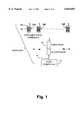
- FIG. 1is a block diagram of the prior art data communication system.
- FIG. 2is perspective view of the invention.
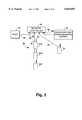
- FIG. 3is a schematic representation of an exemplary radio communication system utilizing the invention.
- FIG. 4is a diagrammatic illustration of the control circuitry elements of the invention.
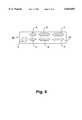
- FIG. 5is a rear elevation view of the invention.
- FIG. 6is a diagrammatic illustration of the application specific integrated circuit of the invention.
- FIG. 7is a bock diagram showing an exemplary implementation of intelligent network and router transceiver units such as the network transceiver units of FIG. 3.
- FIG. 8is a diagram of an RF system utilizing a network controller according to FIGS. 2-6, with one of its network ports configured for communication with a second host, and another of its ports coupled with a multiplicity of RF transceivers via an adapter unit.
- FIG. 9is a diagram illustrating the use of two network controllers according to FIGS. 2-6, configured for dual host computers each, and having their relatively high data rate extended distance network ports coupled with a multiplicity of intelligent network and router transceiver units implemented according to FIG. 7.
- FIG. 10is a diagram similar to FIG. 9 but showing the pair of coupled network controllers interfaced to a common relatively high data rate system having multiple hosts (e.g.) a local area network of the Ethernet type or equivalent e.g. fiber optic type).
- hostse.g.
- a local area network of the Ethernet type or equivalente.g. fiber optic type
- FIG. 11is a diagram similar to FIG. 10 but indicating the network controllers being coupled to respective different high data rate multiple host systems (e.g. token ring type local area networks or other individual networks e.g. fiber optic loop networks of the collision-sense multiple-access type).
- host systemse.g. token ring type local area networks or other individual networks e.g. fiber optic loop networks of the collision-sense multiple-access type.
- FIG. 12is a view similar to FIG. 9 but intended to diagrammatically indicate a distribution of network and router transceivers and other elements of an on-line RF data collection system over an extensive area of a facility e.g. of one of the types previously mentioned.
- FIG. 13shows an intelligent integrated controller and radio base unit which unifies controller and radio components such as shown in FIG. 7 into a single housing of the size represented in FIGS. 2 and 5.
- FIG. 1shows an existing radio frequency data transmission system 10 wherein a base station transceiver means 11 has a number of mobile transceiver units such as 12A, 12B, . . . , 12N in radio communication therewith.
- a base station transceiver means 11has a number of mobile transceiver units such as 12A, 12B, . . . , 12N in radio communication therewith.
- the base stationmay be comprised of a radio base unit 14 such as the model RB3021 of Norand Corporation, Cedar Rapids, Iowa, which forms part of a product family known as the RT3210 system.
- the radio base 14may receive data from the respective mobile RF terminals, e.g. of type RT3210, and transmit the received data via a network controller and a communications link 16 (e.g. utilizing an RS-232 format) to a host computer 17.
- the data capture terminals 12A, 12B, . . . , 12Nmay each be provided with a keyboard such as 18, a display as at 19, and a bar code scanning capability, e.g. via an instant bar code reader such as shown in U.S. Pat. No. 4,766,300 issued Aug. 23, 1988 and known commercially as the 20/20 High Performance Bar Code Reader of Norand Corporation.
- FIG. 2provides a perspective view of the invention 40 in the preferred embodiment case 20.
- Front panel 22is provided with display 24 and select key 26, up key 28 and down key 30.
- Power indicator 32comprises a low power green light emitting diode which is energized when power is supplied to the invention 10.
- Error condition indicator 34is a yellow LED which is software controlled to be energized if the invention 10 is in error condition.
- FIG. 3discloses a diagrammatic illustration of a radio communication system in accordance with the present invention.
- Invention network controller 40is coupled to host computer 42 such that data may be interchanged between the devices over host communications link 44, which may be either in an RS232C format or selectively in an RS422 format.
- the host communication link 44couples to controller 40 at host port 46.
- First communication port 48 of controller 40provides means for coupling of network 50 to controller 40.
- Network 50comprises a number of base RF transceiver units 52A, 52B and 53B, each of which may be selectively employed in the radio frequency communication of data from mobile transceiver units.
- base transceiver units 52are designed and equipped to be operable in the exchange of data with network controller 40 over network link 56 such that each base transceiver unit 52A, 52B, or 53C may independently exchange data with network controller 40 through first communication port 48.
- first communication port 48is intended for operation with a network such as network 50 of base transceiver units 52A, 52B and 53C, for example, network controller 40 is selectively operated to provide an RS485 interface at first communication port 48.
- First communication port 48may be alternately selected to operate as an RS232C interface, as an RS422 interface, as a proprietary NORAND® Radio One Node Network interface or as a high speed V.35 interface.
- the selection of interface to be provided at first communication port 48is front panel controlled, that is, the user may operate front panel keys 28, 30 and 26 (See FIG. 2) to direct the proper interface to be provided at first communication port 48.
- Base transceiver units 52A, 52B, and 52Care coupled to network link 56 by serial means, rather than parallel means, and each may be caused to transmit or to receive independently from the others while additionally being communicative with network controller 40 in a randomly chosen fashion.
- interface translationis provided within controller 40 such that data communicated at first communication port 48 may be directed to host 42 at port 46 via properly chosen interface means as is required by the host 42 with which communication is intended.
- second communication port 57may be internally switched among interface choices of these types: RS232C, RS422, V.35, RS485 and proprietary NORAND® Radio One Node Network interface.
- second communication port 57is coupled over third link 53 to previously installed base transceiver 54, which heretofore had been used in a prior art system as is illustrated in FIG. 1. Because of limitations of base transceiver 54, it must communicate via RS232C interface format and therefore, second communication port 57 must be selected to operate in RS232C interface mode.
- second communication port 57when second communication port 57 is desired to communicate with a network via RS485 interface, front panel keys 26, 28 and 30 may be manipulated by the user to provide the RS485 interface availability at second communication port 57.
- second communication port 57may be selected to operate as an RS422interface, as a V.35 interface, or as the proprietary NORAND® Radio One Node Network interface.
- Diagnostic port 55provides a fourth communication pathway for network controller 40, providing an asynchronous port operable at 300 to 19,200 baud as an RS232C interface.
- diagnostic port 55may be coupled by diagnostic link 58 to diagnostic device 60 for purposes of error diagnosis of controller 40 by diagnostic device 60, or for reprogramming of memory devices within controller 40 when desired.
- diagnostic device 60comprises a 16-bit microprocessor commonly known as a personal computer or "PC".
- the mode of coupling between diagnostic device 60 and network controller 40may be direct or through remote means by use of a modem.
- a central processing unit 70is provided with at least four data communication ports, illustrated at numerals 71, 72, 73, and 74.
- First data communication port 71may be selectively coupled to RS232 interface member 76 or V.35 interface member 78.
- the choice of whether RS232 interface member 76 or V.35 interface member 78 is chosenis dependent upon the operating characteristics presented by the host computer, such as host computer 42 of FIG. 3, with which network controller 40 will communicate.
- the choice of whether first communication port 71 is coupled to interface member 76 or to interface member 78depends on the front panel selection made by the user by keys 26, 28, and 30 shown in FIG. 2.
- Second communication port 72may be selectively coupled to RS232 member 80 or to RS485 interface member 82 or to RS422 interface member 84 or to NORAND® Radio One Node Network proprietary interface member 86.
- the usermay select second communication port 72 to be coupled to any one of interface members 80, 82, 84, and 86.
- Third communication port 73is identical to second communication, port 72 in functionality, being selectively couplable to RS232 interface member 88, to RS485 interface member 90, to RS422 interface member 92 or to NORAND® Radio One Node Network proprietary interface member 94.
- central processing unit 70 of FIG. 4comprises a MotorolaTM 68302 integrated chip cooperative with an application specific integrated circuit.
- Central processing unit 70employs novel features allowing the bidirectional use of a data communicative line of the MotorolaTM 68302 chip and a single clock signal line to eliminate the need for coder-decoder members to be associated with the MotorolaTM 68305 chip while allowing the use of only one pair of signal wires to be coupled to the RS485 interfaces 82 and 90 of FIG. 4.
- Fourth communication port 74 of central processing unitis coupled to asynchonous RS232 interface member 97 to be available for interconnection of a diagnostic device therewith.
- central processing unit 70Also coupled to central processing unit 70 are display member 24 and keyboard member 31 with which keys 26, 28, and 30 of front panel 22 (FIG. 2) are interactive.
- Memory elementsincluding EPROM element 96, DRAM unit 98, FLASH memory unit 100 and EEPROM element 102 are intercoupled with each other and with central processing unit 70.
- Power supply member 104is selectively attachable to invention network controller 40.
- power supply 104is provided in optional models depending on the country in which it is to be used, power supply 104 being capable of providing satisfactory output power to network controller 40 regardless of the voltage or frequency of the input source provided to power supply 104.
- ASIC 120The application specific integrated circuit (ASIC) used in the invention network controller 40 is disclosed in FIG. 6 and is identified by the numeral 120.
- ASIC 120comprises a central processor unit interface 122 member which is coupled to the central processor unit bus by CPU bus link 124 which extends from ASIC 120.
- CPU bus link 124Also coupled to the CPU bus link 124 is dynamic random access memory (DRAM) timing element 126, which provides network controller 40 with timing signals for the DRAM member 98 illustrated in FIG. 4 when memory refresh of the DRAM 98 is indicated.
- DRAM timing element 126is also coupled exteriorly to the ASIC 120 to DRAM member 98 by DRAM link 127.
- Central processing unit interface 122is coupled to asynchronous signal processing element 128 by signal path 130.
- Asynchronous signal processing element 128comprises a baud rate generator cooperative with a universal asynchronous receiver-transmitter.
- network clock and control member 132which comprises a programmable network clock generator which can be selectively programmed to generate an optional clock speed for a network to be coupled through RS485 interfaces 82 and 90 seen in FIG. 4.
- Network clock and control member 132also provides detection means for detections of failure conditions on a linked network and provides control signals to system components in response thereto, including interrupt signals to programmable interrupt coordinator circuity included in central processing interface 122.
- Network clock and controller member 132provides data encoding by the FM0 standard, then the encoded data may be operated upon by RS485 interfaces 82 and 84 and transmitted and received by single twisted pair means to multiple serially networked base transceiver units exemplified by base transceiver units 52A, 52B, and 52C illustrated in FIG. 3.
- Keyboard controller element 134is coupled to central processing unit interface and provides a link exterior to ASIC 120 to keyboard 31 (See FIG. 3).
- FLASH memory/EEPROM logic control member 136is coupled to central processing unit interface 122 and comprises control functions for FLASH memory element 100 and EEPROM memory element 102 of FIG. 3.
- Central processing unit interface 122is also coupled by line 138 to latches exterior to ASIC 120.
- the base transceiver units 52A, 52B, and 52C illustrated in FIG. 3are communicative with mobile transceiver units by electromagnetic radio means.
- the mobile transceiver unitsmay be associated with bar code scanning devices such as the NORAND® 20/20 High Performance Bar Code Reader whereby the scanning devices scan an object having a bar code associated therewith and collect information stored in the bar code, which information is then transmitted through the mobile transceiver units to base transceiver units such as base transceiver units 52A, 52B, and 52C or base transceiver unit 54 of FIG. 3.
- the bar code data received by said base transceiver unitsis then transmitted, in the example of FIG.
- network controller 40which performs the routing and delivery of the data to the stationary data processor, or processors, such as shown for example, by host 42 of FIG. 3.
- FIG. 7shows a block diagram of a particularly preferred intelligent base transceiver unit known as the RB4000. It will be observed that the components correspond with components of the network controller of FIG. 4, and similar reference numerals (preceded by 7-) have been applied in FIG. 7. Thus, the significance of components 7-70 through 7-73, 7-76, 7-82, 7-96, 7-98, 7-100 and 7-104 will be apparent from the preceding description with respect to FIG. 4 and 6, for example.
- I/O bus 700may be coupled with a spread spectrum transmission (SST) or ultra high frequency (UHF) transceiver 701 which may correspond with any of the transceivers of units 52A, 52B, 52C or 54 previously referred to.
- the network controller 70could have a similar RF transceiver coupled with its data port 72 or 73 and controlled via input/output bus 400, e.g. for direct RF coupling with router transceivers such as 901, 901, FIG. 9.
- a network controller 40is shown with port 71 configured for interface with a host port type SNA V.35 56K/64K bits per second.
- Port 72is shown as configured for communication with a personal computer of the PS/2 type operating asynchronously at 38.4K bits per second.
- Port 74is coupled with a modem 8-60 providing for remote diagnostics and reprogramming of the network controller 40.
- Port 73 of network controller 40is shown as being connected with an adapter component 801 known as the MBA3000.
- an adapter component 801known as the MBA3000.
- a specification for the MBA3000is found in APPENDIX A following this detailed description.
- the adapter 801serves to couple controller 40 sequentially with four radio base transceiver units such as indicated at 811 through 814.
- Component 811is a commercially available radio base known as the RB3021 which utilizes features of Sojka U.S. Pat. No. 4,924,462 and of Mahany U.S. Pat. No. 4,910,794, both assigned to the present assignee, and the disclosures of which are hereby incorporated herein by reference in their entirety.
- Base station 811may communicate with a multiplicity of hand-held RF data terminals such as indicated at 821. Details concerning base transceiver units 812 and 813, 814 are found in the attached APPENDICES B and C, respectively. Base 814 is indicated as being coupled with the adaptor 801 via RF broadband modems 831 and 832. Base units 813 and 814 may communicate with a variety of mobile transceiver units such as those indicated at 833, 834 and 1001, the first two being particularly described in APPENDICES D and E.
- FIG. 9shows two network controllers 40A and 40B each with its host ports configured as with the controller 40 of FIG. 8.
- the second ports 72 of the controllers 40A and 40Bare configured for communication a relatively high data rate relatively along a distance network channel 56 which may have the characteristics of the serial channel 56 of FIG. 3, for example, an RS485 channel operating at 384 kilobits per second (384K bps).
- Network base transceivers 52A, 52B and 52Cmay correspond with the correspondingly numbered transceiver units of FIG. 3, for example, and the network may have additional network transceivers such as 52D which may support communication with the radio terminal 1001 for example.
- network transceiversmay have RF coupling with router transceiver units such as indicated at 901, 902 and 903.
- Router transceiver unit 902is illustrated as a RB4000 intelligent transceiver such as represented in FIG. 7 and having its input/output bus 700 coupled with a peripheral.
- FIG. 10is entirely similar to FIG. 9, for example, except that ports 72 of the controllers 40A and 40B are coupled with separate serial type high data rate network channels, and ports 73 of the respective network controllers are coupled to a very high speed network e.g. in the megabit per second range such as an Ethernet local area network 1000. Suitable interfaces are indicated at 1001 and 1002.
- FIG. 11is entirely similar to FIG. 9 except that the ports 73 of the network controllers 40A and 40B are coupled with respective local area ring type networks which may be separate from each other and each have two or more hosts such as represented in FIG. 9 associated with the respective ring networks such as token rings 1100A and 1100B. Suitable interface means are indicated at 1101 and 1102.
- FIG. 12shows, for example, two network controllers 40A and 40B, each with two host computer units such as 42-1A.
- Host 42-2Ais shown with a printer or other peripheral P1 which may generate bar codes, for example, for replacement of damaged bar codes or the like.
- Another printer P2is shown associated with base 52C, again for example, for producing bar code labels where those are needed in the vicinity of a base station.
- base 52CIn a large warehouse, relatively large distances may be involved for a worker to return to a printer such as P1 to obtain a new bar code label.
- a base 52Fmay have a peripheral P3 associated therewith such as a large screen display, a printer or the like which may supplement the capabilities of a hand-held terminal, for example printing out new bar code labels at a convenient location, or providing a full screen display, rather than the more limited screen display area of the hand-held terminal 12-2.
- a base radio 52Dwhich might be located at the ceiling level of a warehouse became inoperative at a time when qualified repair personnel were not immediately available, with the present system it would be feasible to provide a substitute base radio or base radios, for example, as indicated at 52D1 located at table level or the like.
- the base radio stationsdo not necessarily forward data communications received from a given terminal to a particular host.
- hand-held terminal 12-2may request a path to printer P2, and such a path may be created via base stations 52D1 and 52C.
- Station 52Cupon receipt of the message from terminal 12-2 would not transmit the message to a host but would, for example, produce the desired bar code label by means of printer P2.
- terminal 12-2may have provision for digitizing a voice message which might, for example, be addressed to terminal 12-1.
- the system as illustratedwould be operable to automatically establish a suitable path for example, via stations 52D1, 52C, 52B, 52E and 12-1 for the transmission of this voice message in digital form.
- Successive segments of such a voice messagewould be stored, for example, by the terminal 12-1, and when the complete message was assembled, the segments would be synthesized into a continuous voice message for the user of terminal 12-1 e.g. by means of a speaker 1201 also useful for sending tone signals indicating valid bar code read, etc.
- a hardware systemsuch as illustrated in FIG. 12 may be physically laid out and then upon suitable command to one of the network controllers such as 42-2B, the entire system would be progressively automatically self-configured for efficient operation.
- controller 40Bcould successively try its communications options with its output ports such as 71-73, determining for example, that host processors were coupled with ports 71 and 72, one operating on a 38.4 kilobit per second asynchronous basis and the other presenting a SNA port for the V.35 protocol at 64 kilobits per second.
- one host, 42-1Bmight be a main frame computer, while the other host 42-2B might be a PS/2 type computer system.
- the controller 40Bhaving thus automatically configured itself so as to be compatible with the devices connected to ports 71 and 72, could proceed to transmit via port 73 a suitable inquiry message to the network channel 56.
- Each of the base stationscould operate, for example, on a collision-sense multiple-access basis to respond to the inquiry message from the controller 40B, until each of the successive bases on the network had responded and identified itself.
- Each basefor example, would have a respective unique address identification which it could transmit in response to the inquiry message so as to establish its presence on the network.
- the controller 40Bcould then transmit auto configure commands to the successive bases in turn, instructing the bases to determine what peripherals and router bases such as 52D1, 52E and 52F were within the range of such base, and to report back to the controller.
- bases such as 52C and 52Fcould determine the nature of peripherals P2 and P3 associated therewith so as to be able to respond to an inquiry from a terminal such as 12-2 to advise the terminal that a bar code printer, for example, was within direct RF range.
- the introduction of barrierssuch as a new stack of inventory goods to such transmission between a given base such as 52A and various terminals, could result in the base 52A contacting router base 52E, for example, with a request to become active with respect to the blocked terminals.
- FIG. 13shows an intelligent integrated controller and radio base unit 1300 which is integrated into a single housing or case 1301 corresponding to the case or housing 20 of FIG. 2.
- the housing 1301may be provided with an external antenna as diagrammatically indicated at 1302 with suitable RF coupling to the radio circuitry indicated at 1303.
- Components 13-70 through 13-74, 13-76, 13-78, 13-96, 13-97, 13-98, 13-100, and 13-102may correspond with the correspondingly numbered conponents described with reference to FIG. 4.
- a network controller, or integrated network controller and radio unitis coupled to one or more host computers via a standard interface such as commonly encountered in practice (e.g. RS232, V.35, Ethernet, token ring, FDDI, and so on).
- a standard interfacesuch as commonly encountered in practice (e.g. RS232, V.35, Ethernet, token ring, FDDI, and so on).
- the network controllercan automatically switch to the second host.
- the second hostmay be a truly redundant system, or may be a simpler computer of the PC type (a so-called personal computer) that can simply store transactions until the main host is restored.
- a single hostmay have a second port coupled to a second port of the controller especially if a communication link failure may be a problem.
- two ports of the network controllermay be coupled by separate modems with separate phone lines, leading to separate ports of a single mainframe computer, for example an IBM3090.
- two ports of a network controllermay be connected respectively to two mainframe computers such as the IBM3090.
- the disclosed network controllercan also connect one radio network to two hosts using RS232 or V.35 ports or to many hosts using a local area network such as Ethernet, token ring, or FDDI.
- a number of the disclosed network controllers(for example, up to thirty-two) can be connected together to interface many hosts to a single radio network.
- the hand-held portable terminals in such a networkcan then talk to any of the hosts they choose.
- one port of the disclosed network controlleris coupled via its RS232 interface to a mainframe computer such as the IBM3090
- another of its portsmay be coupled via an FDDI network with a super computer e.g. the Cray X-MP.
- mobile and/or portable terminalscan access either the main frame or the super computer, or in general, any of the hosts that are connected to the network controller.
- four hostscan be on one network.
- a multiplicity of hostsmay be coupled with each local area network so as to be in communication with one or more of the disclosed network controllers.
- a single disclosed network controllercan control two radio networks such as the one indicated at 50 in FIG. 3. Where each network such as 50 is limited to thirty-two devices, the number of devices is doubled with the use of two radio networks.
- Two such radio networksmay also be utilized for the sake of redundancy, with a provision for automatic switch-over from one radio network to the second if a problem develops on the first. Two radio networks may also facilitate the use of different radio technologies in one installation.
- the various multi-drop local area networks referred to herein, for example at 7-82 in FIG. 7 and as represented at 56, 56A, 56B, FIGS. 9 through 12, and at 13-82 in FIG. 13may comprise HDLC based local area networks operating at up to 2.5 megabits per second and using biphase space encoding (FM0) for clock recovery from data.
- FM0biphase space encoding
- the components 86 and 94, FIG. 4, and component 13-11, FIG. 13,provides a low-cost base radio interface using three pairs of twisted conductors.
- One pairprovides a bidirectional RS485 data line.
- Another pairis used for the clock and has an RS422 electrical configuration, and is one directional from the radio to the controller.
- the third twisted pairis also RS422 and is used to communicate from the controller to the radio transceiver to effect mode selection.
- An aspect of the inventionresides in the provision of a network controller having port means selectively configurable for coupling in first mode with network RF transceiver units at a relatively high data rate such as 100 kilobits per second or higher, and for coupling in a second mode with network transceiver units at a relatively low data rate such as about twenty kilobits per second.
- a single port meanssuch as 2, 3 or 5, 6, FIG. 5, can be software configured to interface selectively in the first mode or in the second mode. It is presently less expensive to use two connectors per port rather than a single 37-pin connector for example.
- a network controllersuch as 40 operates two high data rate networks
- one network of RF base transceiverscould operate with the RTC protocol, and the second network could operate according to a different protocol such as that disclosed in pending application Ser. No. 07/660,618 filed on or about Feb. 25, 1991, now abandoned, the disclosure of which being incorporated herein by reference in its entirety.
Landscapes
- Engineering & Computer Science (AREA)
- Computer Networks & Wireless Communication (AREA)
- Signal Processing (AREA)
- Quality & Reliability (AREA)
- Physics & Mathematics (AREA)
- General Physics & Mathematics (AREA)
- Mobile Radio Communication Systems (AREA)
Abstract
Description
Claims (14)
Priority Applications (1)
| Application Number | Priority Date | Filing Date | Title |
|---|---|---|---|
| US08/486,083US5844893A (en) | 1991-05-14 | 1995-06-07 | System for coupling host computer meanswith base transceiver units on a local area network |
Applications Claiming Priority (4)
| Application Number | Priority Date | Filing Date | Title |
|---|---|---|---|
| US70070491A | 1991-05-14 | 1991-05-14 | |
| US5721893A | 1993-05-04 | 1993-05-04 | |
| US27794494A | 1994-06-29 | 1994-06-29 | |
| US08/486,083US5844893A (en) | 1991-05-14 | 1995-06-07 | System for coupling host computer meanswith base transceiver units on a local area network |
Related Parent Applications (1)
| Application Number | Title | Priority Date | Filing Date |
|---|---|---|---|
| US27794494AContinuation | 1990-02-26 | 1994-06-29 |
Publications (1)
| Publication Number | Publication Date |
|---|---|
| US5844893Atrue US5844893A (en) | 1998-12-01 |
Family
ID=46251474
Family Applications (2)
| Application Number | Title | Priority Date | Filing Date |
|---|---|---|---|
| US08/486,083Expired - LifetimeUS5844893A (en) | 1991-05-14 | 1995-06-07 | System for coupling host computer meanswith base transceiver units on a local area network |
| US08/486,017Expired - LifetimeUS5708680A (en) | 1991-05-14 | 1995-06-07 | Network utilizing a controller and base transceivers to route voice packets |
Family Applications After (1)
| Application Number | Title | Priority Date | Filing Date |
|---|---|---|---|
| US08/486,017Expired - LifetimeUS5708680A (en) | 1991-05-14 | 1995-06-07 | Network utilizing a controller and base transceivers to route voice packets |
Country Status (1)
| Country | Link |
|---|---|
| US (2) | US5844893A (en) |
Cited By (107)
| Publication number | Priority date | Publication date | Assignee | Title |
|---|---|---|---|---|
| WO1999038266A1 (en)* | 1998-01-22 | 1999-07-29 | Safi Qureshey | Intelligent radio |
| US6128484A (en)* | 1997-10-07 | 2000-10-03 | International Business Machines Corporation | Wireless transceivers for remotely controlling a computer |
| US6137802A (en)* | 1997-03-25 | 2000-10-24 | Motorola, Inc. | Automatic media switching apparatus and method |
| WO2001055865A1 (en)* | 2000-01-31 | 2001-08-02 | Telemetry Technologies, Inc. | Wireless communication enabled meter and network |
| US6272120B1 (en)* | 1997-01-28 | 2001-08-07 | Cisco Technology, Inc. | Multi-radio bridge |
| US6331972B1 (en)* | 1997-02-03 | 2001-12-18 | Motorola, Inc. | Personal data storage and transaction device system and method |
| US20020002039A1 (en)* | 1998-06-12 | 2002-01-03 | Safi Qureshey | Network-enabled audio device |
| US6374311B1 (en) | 1991-10-01 | 2002-04-16 | Intermec Ip Corp. | Communication network having a plurality of bridging nodes which transmit a beacon to terminal nodes in power saving state that it has messages awaiting delivery |
| US20020072330A1 (en)* | 2000-12-08 | 2002-06-13 | Zhang Franklin Zhigang | Multi-channel redundant wireless network link and device |
| US20020094799A1 (en)* | 2000-01-31 | 2002-07-18 | Elliott Karl E. | Wireless communication enabled meter and network |
| USD464044S1 (en) | 2001-03-16 | 2002-10-08 | Industrial Technology Research Institute | VOIP access gateway |
| USD464958S1 (en) | 2001-12-10 | 2002-10-29 | Adtran, Inc. | Housing assembly for communications equipment |
| US20030065784A1 (en)* | 2001-09-28 | 2003-04-03 | Allan Herrod | Software method for maintaining connectivity between applications during communications by mobile computer terminals operable in wireless networks |
| US6567855B1 (en)* | 1998-01-02 | 2003-05-20 | Intel Corporation | Portable processing system with always on, always connected capability |
| US6584080B1 (en)* | 1999-01-14 | 2003-06-24 | Aero-Vision Technologies, Inc. | Wireless burstable communications repeater |
| US20030158974A1 (en)* | 2002-02-20 | 2003-08-21 | Allan Herrod | Software method for emulating a serial port between applications for enabling communications by mobile bar code readers and computer terminals in wireless networks |
| US6614768B1 (en) | 1989-04-28 | 2003-09-02 | Broadcom Corporation | Enhanced mobility and address resolution in a wireless premises based network |
| US20030198196A1 (en)* | 2002-04-17 | 2003-10-23 | Microsoft Corporation | Reducing idle power consumption in a networked battery operated device |
| US20030203740A1 (en)* | 2002-04-17 | 2003-10-30 | Microsoft Corporation | Power efficient channel scheduling in a wireless network |
| US6654378B1 (en)* | 1992-03-18 | 2003-11-25 | Broadcom Corp. | Transaction control system including portable data terminal and mobile customer service station |
| US6665536B1 (en) | 1993-12-20 | 2003-12-16 | Broadcom Corporation | Local area network having multiple channel wireless access |
| US6697415B1 (en) | 1996-06-03 | 2004-02-24 | Broadcom Corporation | Spread spectrum transceiver module utilizing multiple mode transmission |
| US6714983B1 (en) | 1989-04-14 | 2004-03-30 | Broadcom Corporation | Modular, portable data processing terminal for use in a communication network |
| US6760017B1 (en)* | 1994-09-02 | 2004-07-06 | Nec Corporation | Wireless interface device for communicating with a remote host computer |
| US20040166895A1 (en)* | 1993-08-31 | 2004-08-26 | Koenck Steven E. | Modular, portable data processing terminal for use in a communication network |
| US6910632B2 (en) | 1990-06-07 | 2005-06-28 | Broadcom Corporation | Data processing and communications device with interchangeable modules |
| US20060125141A1 (en)* | 2004-12-15 | 2006-06-15 | Tsau Ju International Ltd. | Method for continuously manufacturing anti-sliperry chopping boards |
| US7126926B1 (en)* | 2000-01-14 | 2006-10-24 | Symbol Technologies, Inc. | Multi-tier wireless communications architecture, applications and methods |
| US20070286144A1 (en)* | 1999-11-10 | 2007-12-13 | Izumi Miyake | Communication terminal apparatus, communication method thereof, and connected destination selection method in wireless lan |
| US7483417B2 (en) | 1996-04-18 | 2009-01-27 | Verizon Services Corp. | Telephony communication via varied redundant networks |
| US7536167B2 (en) | 1991-05-13 | 2009-05-19 | Broadcom Corporation | Network supporting roaming, sleeping terminals |
| US7606575B2 (en) | 1988-08-04 | 2009-10-20 | Broadcom Corporation | Remote radio data communication system with data rate switching |
| US7633919B2 (en) | 1991-10-01 | 2009-12-15 | Broadcom Corporation | Communication network providing wireless and hard-wired dynamic routing |
| US7664097B2 (en) | 1996-04-18 | 2010-02-16 | Verizon Services Corp. | Telephone service via networking |
| US7813332B1 (en) | 1997-03-19 | 2010-10-12 | Verizon Services Corp. | Voice call alternative routing through PSTN and internet networks |
| US7817619B1 (en) | 1996-12-18 | 2010-10-19 | Verizon Services Corp. | Internet long distance telephone service |
| US7830860B2 (en) | 1997-03-11 | 2010-11-09 | Verizon Services Corp. | Packet data network voice call quality monitoring |
| US7873343B2 (en) | 1991-10-01 | 2011-01-18 | Broadcom Corporation | Communication network terminal with sleep capability |
| US7948968B2 (en) | 1997-09-16 | 2011-05-24 | Verizon Communications Inc. | Network session management |
| USD642167S1 (en)* | 2010-08-17 | 2011-07-26 | Multi-Tech Systems, Inc. | Chassis |
| US8019836B2 (en) | 2002-01-02 | 2011-09-13 | Mesh Comm, Llc | Wireless communication enabled meter and network |
| US8138934B2 (en) | 2007-11-25 | 2012-03-20 | Trilliant Networks, Inc. | System and method for false alert filtering of event messages within a network |
| US8144596B2 (en) | 2007-11-25 | 2012-03-27 | Trilliant Networks, Inc. | Communication and message route optimization and messaging in a mesh network |
| US8171364B2 (en) | 2007-11-25 | 2012-05-01 | Trilliant Networks, Inc. | System and method for power outage and restoration notification in an advanced metering infrastructure network |
| US8289182B2 (en) | 2008-11-21 | 2012-10-16 | Trilliant Networks, Inc. | Methods and systems for virtual energy management display |
| US8319658B2 (en) | 2009-03-11 | 2012-11-27 | Trilliant Networks, Inc. | Process, device and system for mapping transformers to meters and locating non-technical line losses |
| US8332055B2 (en) | 2007-11-25 | 2012-12-11 | Trilliant Networks, Inc. | Energy use control system and method |
| US8334787B2 (en) | 2007-10-25 | 2012-12-18 | Trilliant Networks, Inc. | Gas meter having ultra-sensitive magnetic material retrofitted onto meter dial and method for performing meter retrofit |
| US8502640B2 (en) | 2007-11-25 | 2013-08-06 | Trilliant Networks, Inc. | System and method for transmitting and receiving information on a neighborhood area network |
| US8699377B2 (en) | 2008-09-04 | 2014-04-15 | Trilliant Networks, Inc. | System and method for implementing mesh network communications using a mesh network protocol |
| US8761142B2 (en) | 2012-10-19 | 2014-06-24 | Ubiquiti Networks, Inc. | Distributed seamless roaming in wireless networks |
| US8781462B2 (en) | 2009-09-28 | 2014-07-15 | Itron, Inc. | Methodology and apparatus for validating network coverage |
| US8832428B2 (en) | 2010-11-15 | 2014-09-09 | Trilliant Holdings Inc. | System and method for securely communicating across multiple networks using a single radio |
| US8836601B2 (en) | 2013-02-04 | 2014-09-16 | Ubiquiti Networks, Inc. | Dual receiver/transmitter radio devices with choke |
| US8856323B2 (en) | 2011-02-10 | 2014-10-07 | Trilliant Holdings, Inc. | Device and method for facilitating secure communications over a cellular network |
| US8855730B2 (en) | 2013-02-08 | 2014-10-07 | Ubiquiti Networks, Inc. | Transmission and reception of high-speed wireless communication using a stacked array antenna |
| US8891338B2 (en) | 2009-01-29 | 2014-11-18 | Itron, Inc. | Measuring the accuracy of an endpoint clock from a remote device |
| US8938062B2 (en) | 1995-12-11 | 2015-01-20 | Comcast Ip Holdings I, Llc | Method for accessing service resource items that are for use in a telecommunications system |
| US8970394B2 (en) | 2011-01-25 | 2015-03-03 | Trilliant Holdings Inc. | Aggregated real-time power outages/restoration reporting (RTPOR) in a secure mesh network |
| US9001787B1 (en) | 2011-09-20 | 2015-04-07 | Trilliant Networks Inc. | System and method for implementing handover of a hybrid communications module |
| US9013173B2 (en) | 2010-09-13 | 2015-04-21 | Trilliant Networks, Inc. | Process for detecting energy theft |
| US9041349B2 (en) | 2011-03-08 | 2015-05-26 | Trilliant Networks, Inc. | System and method for managing load distribution across a power grid |
| US9084120B2 (en) | 2010-08-27 | 2015-07-14 | Trilliant Networks Inc. | System and method for interference free operation of co-located transceivers |
| US9172605B2 (en) | 2014-03-07 | 2015-10-27 | Ubiquiti Networks, Inc. | Cloud device identification and authentication |
| US9191505B2 (en) | 2009-05-28 | 2015-11-17 | Comcast Cable Communications, Llc | Stateful home phone service |
| US9191037B2 (en) | 2013-10-11 | 2015-11-17 | Ubiquiti Networks, Inc. | Wireless radio system optimization by persistent spectrum analysis |
| US9197314B1 (en) | 2013-11-08 | 2015-11-24 | Gogo Llc | Data delivery to devices on vehicles using multiple forward links |
| US9232546B2 (en) | 2013-11-08 | 2016-01-05 | Gogo Llc | Systems and methods for two-part electronic device registration |
| US9282383B2 (en) | 2011-01-14 | 2016-03-08 | Trilliant Incorporated | Process, device and system for volt/VAR optimization |
| US9326217B2 (en) | 2013-11-08 | 2016-04-26 | Gogo Llc | Optimizing usage of modems for data delivery to devices on vehicles |
| US9325516B2 (en) | 2014-03-07 | 2016-04-26 | Ubiquiti Networks, Inc. | Power receptacle wireless access point devices for networked living and work spaces |
| US9368870B2 (en) | 2014-03-17 | 2016-06-14 | Ubiquiti Networks, Inc. | Methods of operating an access point using a plurality of directional beams |
| US9369991B2 (en) | 2013-11-08 | 2016-06-14 | Gogo Llc | Hybrid communications for devices on vehicles |
| US9397820B2 (en) | 2013-02-04 | 2016-07-19 | Ubiquiti Networks, Inc. | Agile duplexing wireless radio devices |
| US9467828B2 (en) | 2013-11-08 | 2016-10-11 | Gogo Llc | Systems and methods for configuring an electronic device for cellular-based communications |
| US9496620B2 (en) | 2013-02-04 | 2016-11-15 | Ubiquiti Networks, Inc. | Radio system for long-range high-speed wireless communication |
| US9503956B2 (en) | 2014-05-30 | 2016-11-22 | Gogo Llc | Systems and methods for facilitating communications originating from a non-terrestrial network |
| US9516370B1 (en) | 2004-05-05 | 2016-12-06 | Black Hills Media, Llc | Method, device, and system for directing a wireless speaker from a mobile phone to receive and render a playlist from a content server on the internet |
| US9543635B2 (en) | 2013-02-04 | 2017-01-10 | Ubiquiti Networks, Inc. | Operation of radio devices for long-range high-speed wireless communication |
| US9577857B2 (en) | 2013-11-08 | 2017-02-21 | Gogo Llc | Adaptive modulation in a hybrid vehicle communication system |
| US20170081149A1 (en)* | 2015-09-21 | 2017-03-23 | Thyssenkrupp Elevator Ag | Hoistway Communication System |
| US9634373B2 (en) | 2009-06-04 | 2017-04-25 | Ubiquiti Networks, Inc. | Antenna isolation shrouds and reflectors |
| US9648468B2 (en) | 2014-05-01 | 2017-05-09 | Gogo Llc | Systems and methods for facilitating voice-based communications |
| US9655073B2 (en) | 2014-05-30 | 2017-05-16 | Gogo Llc | Systems and methods for communicating with non-terrestrial electronic devices |
| US9680704B2 (en) | 2015-09-25 | 2017-06-13 | Ubiquiti Networks, Inc. | Compact and integrated key controller apparatus for monitoring networks |
| US9693428B2 (en) | 2014-10-15 | 2017-06-27 | Abl Ip Holding Llc | Lighting control with automated activation process |
| US9712668B2 (en) | 2014-05-01 | 2017-07-18 | Gogo Llc | Systems and methods for notifying electronic devices of voice-based communication requests |
| US9716542B2 (en) | 2014-05-30 | 2017-07-25 | Gogo Llc | Systems and methods for facilitating communications destined for a non-terrestrial network |
| US9761954B2 (en) | 2015-10-09 | 2017-09-12 | Ubiquiti Networks, Inc. | Synchronized multiple-radio antenna systems and methods |
| US9781814B2 (en) | 2014-10-15 | 2017-10-03 | Abl Ip Holding Llc | Lighting control with integral dimming |
| US9912034B2 (en) | 2014-04-01 | 2018-03-06 | Ubiquiti Networks, Inc. | Antenna assembly |
| US9967020B2 (en) | 2013-11-08 | 2018-05-08 | Gogo Llc | Facilitating communications between on-board electronic devices and terrestrial devices |
| US10069580B2 (en) | 2014-06-30 | 2018-09-04 | Ubiquiti Networks, Inc. | Wireless radio device alignment tools and methods |
| US10136233B2 (en) | 2015-09-11 | 2018-11-20 | Ubiquiti Networks, Inc. | Compact public address access point apparatuses |
| US10142989B2 (en) | 2014-08-31 | 2018-11-27 | Ubiquiti Networks, Inc. | Methods and apparatuses for graphically indicating station efficiency and pseudo-dynamic error vector magnitude information for a network of wireless stations |
| US10164332B2 (en) | 2014-10-14 | 2018-12-25 | Ubiquiti Networks, Inc. | Multi-sector antennas |
| US10194328B2 (en) | 2014-06-30 | 2019-01-29 | Ubiquiti Networks, Inc. | Methods and tools for persistent spectrum analysis of an operating radio frequency band |
| US10284268B2 (en) | 2015-02-23 | 2019-05-07 | Ubiquiti Networks, Inc. | Radio apparatuses for long-range communication of radio-frequency information |
| US10425536B2 (en) | 2014-05-08 | 2019-09-24 | Ubiquiti Networks, Inc. | Phone systems and methods of communication |
| USD876407S1 (en)* | 2015-07-30 | 2020-02-25 | Arris Enterprises, Inc. | Wireless voice gateway enclosure |
| US10574474B2 (en) | 2014-03-07 | 2020-02-25 | Ubiquiti Inc. | Integrated power receptacle wireless access point (AP) adapter devices |
| US10924641B2 (en) | 2017-07-10 | 2021-02-16 | Ubiquiti Inc. | Wearable video camera medallion with circular display |
| US11258764B2 (en) | 2017-09-27 | 2022-02-22 | Ubiquiti Inc. | Systems for automatic secured remote access to a local network |
| US11482352B2 (en) | 2018-01-09 | 2022-10-25 | Ubiquiti Inc. | Quick connecting twisted pair cables |
| US11677688B2 (en) | 2019-09-13 | 2023-06-13 | Ubiquiti Inc. | Augmented reality for internet connectivity installation |
| US11909087B2 (en) | 2013-02-04 | 2024-02-20 | Ubiquiti Inc. | Coaxial RF dual-polarized waveguide filter and method |
| US12231892B2 (en) | 2017-09-27 | 2025-02-18 | Ubiquiti Inc. | Systems for automatic secured remote access to a local network |
Families Citing this family (8)
| Publication number | Priority date | Publication date | Assignee | Title |
|---|---|---|---|---|
| US20010050943A1 (en)* | 1989-08-03 | 2001-12-13 | Mahany Ronald L. | Radio frequency communication network having adaptive communication parameters |
| US6970434B1 (en)* | 1995-06-07 | 2005-11-29 | Broadcom Corporation | Hierarchical communication system providing intelligent data, program and processing migration |
| US7387253B1 (en)* | 1996-09-03 | 2008-06-17 | Hand Held Products, Inc. | Optical reader system comprising local host processor and optical reader |
| US7444394B2 (en)* | 1997-02-03 | 2008-10-28 | Canon Kabushiki Kaisha | Network data base control device and method thereof |
| US6061339A (en)* | 1997-12-10 | 2000-05-09 | L-3 Communications Corporation | Fixed wireless loop system having adaptive system capacity based on estimated signal to noise ratio |
| US6290131B1 (en)* | 1999-05-12 | 2001-09-18 | Metrologic Instruments, Inc. | Optical scanner adapted for direct interfacing to a data communications network |
| AU2001294142A1 (en)* | 2000-09-20 | 2002-04-02 | Main.Net Communication Ltd. | Multimedia communications over power lines |
| US7111787B2 (en)* | 2001-05-15 | 2006-09-26 | Hand Held Products, Inc. | Multimode image capturing and decoding optical reader |
Citations (7)
| Publication number | Priority date | Publication date | Assignee | Title |
|---|---|---|---|---|
| US4414661A (en)* | 1981-07-02 | 1983-11-08 | Trancom Ab | Apparatus for communicating with a fleet of vehicles |
| US4837858A (en)* | 1987-04-30 | 1989-06-06 | Motorola, Inc. | Subscriber unit for a trunked voice/data communication system |
| US4940974A (en)* | 1988-11-01 | 1990-07-10 | Norand Corporation | Multiterminal communication system and method |
| US4984247A (en)* | 1988-09-29 | 1991-01-08 | Ascom Zelcom Ag | Digital radio transmission system for a cellular network, using the spread spectrum method |
| US5070536A (en)* | 1988-08-04 | 1991-12-03 | Norand Corporation | Mobile radio data communication system and method |
| US5142534A (en)* | 1990-10-17 | 1992-08-25 | O'neill Communications, Inc. | Wireless integrated voice-data communication system |
| US5297144A (en)* | 1991-01-22 | 1994-03-22 | Spectrix Corporation | Reservation-based polling protocol for a wireless data communications network |
Family Cites Families (2)
| Publication number | Priority date | Publication date | Assignee | Title |
|---|---|---|---|---|
| US4241447A (en)* | 1969-07-22 | 1980-12-23 | International Telephone And Telegraph Corporation | Secure spread spectrum communication system |
| US3764915A (en)* | 1971-06-25 | 1973-10-09 | Bell Telephone Labor Inc | Dynamic program control for channel assignment in mobile communication systems |
- 1995
- 1995-06-07USUS08/486,083patent/US5844893A/ennot_activeExpired - Lifetime
- 1995-06-07USUS08/486,017patent/US5708680A/ennot_activeExpired - Lifetime
Patent Citations (7)
| Publication number | Priority date | Publication date | Assignee | Title |
|---|---|---|---|---|
| US4414661A (en)* | 1981-07-02 | 1983-11-08 | Trancom Ab | Apparatus for communicating with a fleet of vehicles |
| US4837858A (en)* | 1987-04-30 | 1989-06-06 | Motorola, Inc. | Subscriber unit for a trunked voice/data communication system |
| US5070536A (en)* | 1988-08-04 | 1991-12-03 | Norand Corporation | Mobile radio data communication system and method |
| US4984247A (en)* | 1988-09-29 | 1991-01-08 | Ascom Zelcom Ag | Digital radio transmission system for a cellular network, using the spread spectrum method |
| US4940974A (en)* | 1988-11-01 | 1990-07-10 | Norand Corporation | Multiterminal communication system and method |
| US5142534A (en)* | 1990-10-17 | 1992-08-25 | O'neill Communications, Inc. | Wireless integrated voice-data communication system |
| US5297144A (en)* | 1991-01-22 | 1994-03-22 | Spectrix Corporation | Reservation-based polling protocol for a wireless data communications network |
Cited By (223)
| Publication number | Priority date | Publication date | Assignee | Title |
|---|---|---|---|---|
| US7606575B2 (en) | 1988-08-04 | 2009-10-20 | Broadcom Corporation | Remote radio data communication system with data rate switching |
| US7672674B2 (en) | 1988-08-04 | 2010-03-02 | Broadcom Corporation | Remote radio data communication system with data rate switching |
| US6714983B1 (en) | 1989-04-14 | 2004-03-30 | Broadcom Corporation | Modular, portable data processing terminal for use in a communication network |
| US6614768B1 (en) | 1989-04-28 | 2003-09-02 | Broadcom Corporation | Enhanced mobility and address resolution in a wireless premises based network |
| US6910632B2 (en) | 1990-06-07 | 2005-06-28 | Broadcom Corporation | Data processing and communications device with interchangeable modules |
| US7826818B2 (en) | 1991-05-13 | 2010-11-02 | Broadcom Corporation | Network supporting roaming, sleeping terminals |
| US7536167B2 (en) | 1991-05-13 | 2009-05-19 | Broadcom Corporation | Network supporting roaming, sleeping terminals |
| US7907577B2 (en) | 1991-10-01 | 2011-03-15 | Broadcom Corporation | Communication network providing wireless and hard-wired dynamic routing |
| US7873343B2 (en) | 1991-10-01 | 2011-01-18 | Broadcom Corporation | Communication network terminal with sleep capability |
| US7633919B2 (en) | 1991-10-01 | 2009-12-15 | Broadcom Corporation | Communication network providing wireless and hard-wired dynamic routing |
| US6374311B1 (en) | 1991-10-01 | 2002-04-16 | Intermec Ip Corp. | Communication network having a plurality of bridging nodes which transmit a beacon to terminal nodes in power saving state that it has messages awaiting delivery |
| US7558557B1 (en) | 1991-11-12 | 2009-07-07 | Broadcom Corporation | Low-power messaging in a network supporting roaming terminals |
| US6654378B1 (en)* | 1992-03-18 | 2003-11-25 | Broadcom Corp. | Transaction control system including portable data terminal and mobile customer service station |
| US8509260B2 (en) | 1993-08-31 | 2013-08-13 | Broadcom Corporation | Modular, portable data processing terminal for use in a communication network |
| US20040166895A1 (en)* | 1993-08-31 | 2004-08-26 | Koenck Steven E. | Modular, portable data processing terminal for use in a communication network |
| US7710935B2 (en) | 1993-12-20 | 2010-05-04 | Broadcom Corporation | Local area network having multiple channel wireless access |
| US7710907B2 (en) | 1993-12-20 | 2010-05-04 | Broadcom Corporation | Local area network having multiple channel wireless access |
| US6665536B1 (en) | 1993-12-20 | 2003-12-16 | Broadcom Corporation | Local area network having multiple channel wireless access |
| US7856003B2 (en) | 1993-12-20 | 2010-12-21 | Broadcom Corporation | Local area network having multiple channel wireless access |
| US6760017B1 (en)* | 1994-09-02 | 2004-07-06 | Nec Corporation | Wireless interface device for communicating with a remote host computer |
| US8938062B2 (en) | 1995-12-11 | 2015-01-20 | Comcast Ip Holdings I, Llc | Method for accessing service resource items that are for use in a telecommunications system |
| US7664097B2 (en) | 1996-04-18 | 2010-02-16 | Verizon Services Corp. | Telephone service via networking |
| US7483417B2 (en) | 1996-04-18 | 2009-01-27 | Verizon Services Corp. | Telephony communication via varied redundant networks |
| US8379531B2 (en) | 1996-04-18 | 2013-02-19 | Verizon Services Corp. | Telephony communication via varied redundant networks |
| US6697415B1 (en) | 1996-06-03 | 2004-02-24 | Broadcom Corporation | Spread spectrum transceiver module utilizing multiple mode transmission |
| US7676198B2 (en)* | 1996-06-03 | 2010-03-09 | Broadcom Corporation | Spread spectrum transceiver module utilizing multiple mode transmission |
| US8553681B2 (en) | 1996-06-26 | 2013-10-08 | Verizon Services Corp. | Telephone service via packet-switched networking |
| US7817619B1 (en) | 1996-12-18 | 2010-10-19 | Verizon Services Corp. | Internet long distance telephone service |
| US6272120B1 (en)* | 1997-01-28 | 2001-08-07 | Cisco Technology, Inc. | Multi-radio bridge |
| US6331972B1 (en)* | 1997-02-03 | 2001-12-18 | Motorola, Inc. | Personal data storage and transaction device system and method |
| US7830860B2 (en) | 1997-03-11 | 2010-11-09 | Verizon Services Corp. | Packet data network voice call quality monitoring |
| US7813332B1 (en) | 1997-03-19 | 2010-10-12 | Verizon Services Corp. | Voice call alternative routing through PSTN and internet networks |
| US6137802A (en)* | 1997-03-25 | 2000-10-24 | Motorola, Inc. | Automatic media switching apparatus and method |
| US9215254B1 (en) | 1997-09-16 | 2015-12-15 | Verizon Patent And Licensing Inc. | Network session management for telephony over hybrid networks |
| US8976782B1 (en) | 1997-09-16 | 2015-03-10 | Verizon Patent And Licensing Inc. | Network session management for telephony over hybrid networks |
| US7948968B2 (en) | 1997-09-16 | 2011-05-24 | Verizon Communications Inc. | Network session management |
| US6128484A (en)* | 1997-10-07 | 2000-10-03 | International Business Machines Corporation | Wireless transceivers for remotely controlling a computer |
| US6567855B1 (en)* | 1998-01-02 | 2003-05-20 | Intel Corporation | Portable processing system with always on, always connected capability |
| US9552188B1 (en) | 1998-01-22 | 2017-01-24 | Black Hills Media, Llc | Method and device for displaying supplemental information while rendering a playlist |
| WO1999038266A1 (en)* | 1998-01-22 | 1999-07-29 | Safi Qureshey | Intelligent radio |
| US8045952B2 (en) | 1998-01-22 | 2011-10-25 | Horsham Enterprises, Llc | Method and device for obtaining playlist content over a network |
| US8755763B2 (en) | 1998-01-22 | 2014-06-17 | Black Hills Media | Method and device for an internet radio capable of obtaining playlist content from a content server |
| US8050652B2 (en) | 1998-01-22 | 2011-11-01 | Horsham Enterprises, Llc | Method and device for an internet radio capable of obtaining playlist content from a content server |
| US9549001B1 (en) | 1998-01-22 | 2017-01-17 | Black Hills Media, Llc | Method and device for sourcing and constructing a playlist |
| US9397627B2 (en) | 1998-01-22 | 2016-07-19 | Black Hills Media, Llc | Network-enabled audio device |
| US9312827B2 (en) | 1998-01-22 | 2016-04-12 | Black Hills Media, Llc | Network enabled audio device and radio site |
| US20070089132A1 (en)* | 1998-01-22 | 2007-04-19 | Concert Technology Corporation | Network-enabled audio device |
| US8792850B2 (en) | 1998-01-22 | 2014-07-29 | Black Hills Media | Method and device for obtaining playlist content over a network |
| US20070089135A1 (en)* | 1998-01-22 | 2007-04-19 | Concert Technology Corporation | Network-enabled audio device |
| US8918480B2 (en) | 1998-01-22 | 2014-12-23 | Black Hills Media, Llc | Method, system, and device for the distribution of internet radio content |
| US20020002039A1 (en)* | 1998-06-12 | 2002-01-03 | Safi Qureshey | Network-enabled audio device |
| US6584080B1 (en)* | 1999-01-14 | 2003-06-24 | Aero-Vision Technologies, Inc. | Wireless burstable communications repeater |
| US20070286144A1 (en)* | 1999-11-10 | 2007-12-13 | Izumi Miyake | Communication terminal apparatus, communication method thereof, and connected destination selection method in wireless lan |
| US7907583B2 (en) | 1999-11-10 | 2011-03-15 | Fujifilm Corporation | Communication terminal apparatus, communication method thereof, and connected destination selection method in wireless LAN |
| US7403510B1 (en)* | 1999-11-10 | 2008-07-22 | Fujifilm Corporation | Communication terminal apparatus, communication method thereof, and connected destination selection method in wireless LAN |
| US7126926B1 (en)* | 2000-01-14 | 2006-10-24 | Symbol Technologies, Inc. | Multi-tier wireless communications architecture, applications and methods |
| US7492248B1 (en) | 2000-01-14 | 2009-02-17 | Symbol Technologies, Inc. | Multi-tier wireless communications architecture, applications and methods |
| US20020094799A1 (en)* | 2000-01-31 | 2002-07-18 | Elliott Karl E. | Wireless communication enabled meter and network |
| US7379981B2 (en) | 2000-01-31 | 2008-05-27 | Kenneth W. Garrard | Wireless communication enabled meter and network |
| US8700749B2 (en) | 2000-01-31 | 2014-04-15 | Endeavor Ip, Inc. | Wireless communication enabled meter and network |
| US8855019B2 (en) | 2000-01-31 | 2014-10-07 | Endeavor Meshtech, Inc. | Wireless communication enabled meter and network |
| WO2001055865A1 (en)* | 2000-01-31 | 2001-08-02 | Telemetry Technologies, Inc. | Wireless communication enabled meter and network |
| US10067739B2 (en) | 2000-11-08 | 2018-09-04 | Black Hills Media, Llc | Unitary electronic speaker device for receiving digital audio data and rendering the digital audio data |
| US9369101B2 (en) | 2000-11-08 | 2016-06-14 | Black Hills Media, Llc | Unitary electronic speaker device for receiving an assignment of a playlist from a home personal computer and rendering the playlist |
| US20020072330A1 (en)* | 2000-12-08 | 2002-06-13 | Zhang Franklin Zhigang | Multi-channel redundant wireless network link and device |
| US7136619B2 (en)* | 2000-12-08 | 2006-11-14 | Franklin Zhigang Zhang | Multi-channel redundant wireless network link and device |
| USD464044S1 (en) | 2001-03-16 | 2002-10-08 | Industrial Technology Research Institute | VOIP access gateway |
| US20030065784A1 (en)* | 2001-09-28 | 2003-04-03 | Allan Herrod | Software method for maintaining connectivity between applications during communications by mobile computer terminals operable in wireless networks |
| US7225260B2 (en) | 2001-09-28 | 2007-05-29 | Symbol Technologies, Inc. | Software method for maintaining connectivity between applications during communications by mobile computer terminals operable in wireless networks |
| USD464958S1 (en) | 2001-12-10 | 2002-10-29 | Adtran, Inc. | Housing assembly for communications equipment |
| US8019836B2 (en) | 2002-01-02 | 2011-09-13 | Mesh Comm, Llc | Wireless communication enabled meter and network |
| US7461384B2 (en) | 2002-02-20 | 2008-12-02 | Symbol Technologies, Inc. | Software method for emulating a serial port between applications for enabling communications by mobile bar code readers and computer terminals in wireless networks |
| US20030158974A1 (en)* | 2002-02-20 | 2003-08-21 | Allan Herrod | Software method for emulating a serial port between applications for enabling communications by mobile bar code readers and computer terminals in wireless networks |
| US20050096073A1 (en)* | 2002-04-17 | 2005-05-05 | Microsoft Corporation | Power efficient channel scheduling in a wireless network |
| US20030198196A1 (en)* | 2002-04-17 | 2003-10-23 | Microsoft Corporation | Reducing idle power consumption in a networked battery operated device |
| US20060142035A1 (en)* | 2002-04-17 | 2006-06-29 | Microsoft Corporation | Power efficient channel scheduling in a wireless network |
| US20050136922A1 (en)* | 2002-04-17 | 2005-06-23 | Microsoft Corporation | Power efficient channel scheduling in a wireless network |
| US20060160559A1 (en)* | 2002-04-17 | 2006-07-20 | Microsoft Corporation | Reducing idle power consumption in a networked battery operated device |
| US20050113128A1 (en)* | 2002-04-17 | 2005-05-26 | Microsoft Corporation | Power efficient channel scheduling in a wireless network |
| US7110783B2 (en) | 2002-04-17 | 2006-09-19 | Microsoft Corporation | Power efficient channel scheduling in a wireless network |
| US7142855B2 (en) | 2002-04-17 | 2006-11-28 | Microsoft Corporation | Power efficient channel scheduling in a wireless network |
| US7203463B2 (en) | 2002-04-17 | 2007-04-10 | Microsoft Corporation | Power efficient channel scheduling in a wireless network |
| US7539508B2 (en) | 2002-04-17 | 2009-05-26 | Microsoft Corporation | Reducing idle power consumption in a networked battery operated device |
| US20030203740A1 (en)* | 2002-04-17 | 2003-10-30 | Microsoft Corporation | Power efficient channel scheduling in a wireless network |
| US7209740B2 (en) | 2002-04-17 | 2007-04-24 | Microsoft Corporation | Power efficient channel scheduling in a wireless network |
| US7245936B2 (en) | 2002-04-17 | 2007-07-17 | Microsoft Corporation | Power efficient channel scheduling in a wireless network |
| US9554405B2 (en) | 2004-05-05 | 2017-01-24 | Black Hills Media, Llc | Wireless speaker for receiving from a mobile phone directions to receive and render a playlist from a content server on the internet |
| US9516370B1 (en) | 2004-05-05 | 2016-12-06 | Black Hills Media, Llc | Method, device, and system for directing a wireless speaker from a mobile phone to receive and render a playlist from a content server on the internet |
| US20060125141A1 (en)* | 2004-12-15 | 2006-06-15 | Tsau Ju International Ltd. | Method for continuously manufacturing anti-sliperry chopping boards |
| US8334787B2 (en) | 2007-10-25 | 2012-12-18 | Trilliant Networks, Inc. | Gas meter having ultra-sensitive magnetic material retrofitted onto meter dial and method for performing meter retrofit |
| US8725274B2 (en) | 2007-11-25 | 2014-05-13 | Trilliant Networks, Inc. | Energy use control system and method |
| US8171364B2 (en) | 2007-11-25 | 2012-05-01 | Trilliant Networks, Inc. | System and method for power outage and restoration notification in an advanced metering infrastructure network |
| US8138934B2 (en) | 2007-11-25 | 2012-03-20 | Trilliant Networks, Inc. | System and method for false alert filtering of event messages within a network |
| US8502640B2 (en) | 2007-11-25 | 2013-08-06 | Trilliant Networks, Inc. | System and method for transmitting and receiving information on a neighborhood area network |
| US8144596B2 (en) | 2007-11-25 | 2012-03-27 | Trilliant Networks, Inc. | Communication and message route optimization and messaging in a mesh network |
| US8332055B2 (en) | 2007-11-25 | 2012-12-11 | Trilliant Networks, Inc. | Energy use control system and method |
| US8370697B2 (en) | 2007-11-25 | 2013-02-05 | Trilliant Networks, Inc. | System and method for power outage and restoration notification in an advanced metering infrastructure network |
| US8699377B2 (en) | 2008-09-04 | 2014-04-15 | Trilliant Networks, Inc. | System and method for implementing mesh network communications using a mesh network protocol |
| US9621457B2 (en) | 2008-09-04 | 2017-04-11 | Trilliant Networks, Inc. | System and method for implementing mesh network communications using a mesh network protocol |
| US8289182B2 (en) | 2008-11-21 | 2012-10-16 | Trilliant Networks, Inc. | Methods and systems for virtual energy management display |
| US8891338B2 (en) | 2009-01-29 | 2014-11-18 | Itron, Inc. | Measuring the accuracy of an endpoint clock from a remote device |
| US9189822B2 (en) | 2009-03-11 | 2015-11-17 | Trilliant Networks, Inc. | Process, device and system for mapping transformers to meters and locating non-technical line losses |
| US8319658B2 (en) | 2009-03-11 | 2012-11-27 | Trilliant Networks, Inc. | Process, device and system for mapping transformers to meters and locating non-technical line losses |
| US9191505B2 (en) | 2009-05-28 | 2015-11-17 | Comcast Cable Communications, Llc | Stateful home phone service |
| US10756422B2 (en) | 2009-06-04 | 2020-08-25 | Ubiquiti Inc. | Antenna isolation shrouds and reflectors |
| US9634373B2 (en) | 2009-06-04 | 2017-04-25 | Ubiquiti Networks, Inc. | Antenna isolation shrouds and reflectors |
| US8781462B2 (en) | 2009-09-28 | 2014-07-15 | Itron, Inc. | Methodology and apparatus for validating network coverage |
| USD642167S1 (en)* | 2010-08-17 | 2011-07-26 | Multi-Tech Systems, Inc. | Chassis |
| US9084120B2 (en) | 2010-08-27 | 2015-07-14 | Trilliant Networks Inc. | System and method for interference free operation of co-located transceivers |
| US9013173B2 (en) | 2010-09-13 | 2015-04-21 | Trilliant Networks, Inc. | Process for detecting energy theft |
| US8832428B2 (en) | 2010-11-15 | 2014-09-09 | Trilliant Holdings Inc. | System and method for securely communicating across multiple networks using a single radio |
| US9282383B2 (en) | 2011-01-14 | 2016-03-08 | Trilliant Incorporated | Process, device and system for volt/VAR optimization |
| US8970394B2 (en) | 2011-01-25 | 2015-03-03 | Trilliant Holdings Inc. | Aggregated real-time power outages/restoration reporting (RTPOR) in a secure mesh network |
| US8856323B2 (en) | 2011-02-10 | 2014-10-07 | Trilliant Holdings, Inc. | Device and method for facilitating secure communications over a cellular network |
| US9041349B2 (en) | 2011-03-08 | 2015-05-26 | Trilliant Networks, Inc. | System and method for managing load distribution across a power grid |
| US9001787B1 (en) | 2011-09-20 | 2015-04-07 | Trilliant Networks Inc. | System and method for implementing handover of a hybrid communications module |
| US9258753B2 (en) | 2012-10-19 | 2016-02-09 | Ubiquiti Networks, Inc. | Distributed seamless roaming in wireless networks |
| US9008126B2 (en) | 2012-10-19 | 2015-04-14 | Ubiquiti Networks, Inc. | Distributed seamless roaming in wireless networks |
| US8761142B2 (en) | 2012-10-19 | 2014-06-24 | Ubiquiti Networks, Inc. | Distributed seamless roaming in wireless networks |
| US8879574B2 (en) | 2012-10-19 | 2014-11-04 | Ubiquiti Networks, Inc. | Distributed seamless roaming in wireless networks |
| US10165477B2 (en) | 2012-10-19 | 2018-12-25 | Ubiquiti Networks, Inc. | Distributed seamless roaming in wireless networks |
| US9730117B2 (en) | 2012-10-19 | 2017-08-08 | Ubiquiti Networks, Inc. | Distributed seamless roaming in wireless networks |
| US9543635B2 (en) | 2013-02-04 | 2017-01-10 | Ubiquiti Networks, Inc. | Operation of radio devices for long-range high-speed wireless communication |
| US12308504B2 (en) | 2013-02-04 | 2025-05-20 | Ubiquiti Inc. | Coaxial RF dual-polarized waveguide filter and method |
| US9397820B2 (en) | 2013-02-04 | 2016-07-19 | Ubiquiti Networks, Inc. | Agile duplexing wireless radio devices |
| US11909087B2 (en) | 2013-02-04 | 2024-02-20 | Ubiquiti Inc. | Coaxial RF dual-polarized waveguide filter and method |
| US9490533B2 (en) | 2013-02-04 | 2016-11-08 | Ubiquiti Networks, Inc. | Dual receiver/transmitter radio devices with choke |
| US9496620B2 (en) | 2013-02-04 | 2016-11-15 | Ubiquiti Networks, Inc. | Radio system for long-range high-speed wireless communication |
| US10312598B2 (en) | 2013-02-04 | 2019-06-04 | Ubiquiti Networks, Inc. | Radio system for long-range high-speed wireless communication |
| US9972912B2 (en) | 2013-02-04 | 2018-05-15 | Ubiquiti Networks, Inc. | Radio system for long-range high-speed wireless communication |
| US8836601B2 (en) | 2013-02-04 | 2014-09-16 | Ubiquiti Networks, Inc. | Dual receiver/transmitter radio devices with choke |
| US10819037B2 (en) | 2013-02-04 | 2020-10-27 | Ubiquiti Inc. | Radio system for long-range high-speed wireless communication |
| US9373885B2 (en) | 2013-02-08 | 2016-06-21 | Ubiquiti Networks, Inc. | Radio system for high-speed wireless communication |
| US9531067B2 (en) | 2013-02-08 | 2016-12-27 | Ubiquiti Networks, Inc. | Adjustable-tilt housing with flattened dome shape, array antenna, and bracket mount |
| US11011835B2 (en) | 2013-02-08 | 2021-05-18 | Ubiquiti Inc. | Adjustable-tilt housing with flattened dome shape, array antenna, and bracket mount |
| US9293817B2 (en) | 2013-02-08 | 2016-03-22 | Ubiquiti Networks, Inc. | Stacked array antennas for high-speed wireless communication |
| US8855730B2 (en) | 2013-02-08 | 2014-10-07 | Ubiquiti Networks, Inc. | Transmission and reception of high-speed wireless communication using a stacked array antenna |
| US11670844B2 (en) | 2013-02-08 | 2023-06-06 | Ubiquiti Inc. | Adjustable-tilt housing with flattened dome shape, array antenna, and bracket mount |
| US10170828B2 (en) | 2013-02-08 | 2019-01-01 | Ubiquiti Networks, Inc. | Adjustable-tilt housing with flattened dome shape, array antenna, and bracket mount |
| US9191037B2 (en) | 2013-10-11 | 2015-11-17 | Ubiquiti Networks, Inc. | Wireless radio system optimization by persistent spectrum analysis |
| US11804864B2 (en) | 2013-10-11 | 2023-10-31 | Ubiquiti Inc. | Wireless radio system optimization by persistent spectrum analysis |
| US10205471B2 (en) | 2013-10-11 | 2019-02-12 | Ubiquiti Networks, Inc. | Wireless radio system optimization by persistent spectrum analysis |
| US10623030B2 (en) | 2013-10-11 | 2020-04-14 | Ubiquiti Inc. | Wireless radio system optimization by persistent spectrum analysis |
| US11057061B2 (en) | 2013-10-11 | 2021-07-06 | Ubiquiti Inc. | Wireless radio system optimization by persistent spectrum analysis |
| US12199648B2 (en) | 2013-10-11 | 2025-01-14 | Ubiquiti Inc. | Wireless radio system optimization by persistent spectrum analysis |
| US9973262B2 (en) | 2013-11-08 | 2018-05-15 | Gogo Llc | Data delivery to devices on vehicles using multiple forward links |
| US9369991B2 (en) | 2013-11-08 | 2016-06-14 | Gogo Llc | Hybrid communications for devices on vehicles |
| US9467828B2 (en) | 2013-11-08 | 2016-10-11 | Gogo Llc | Systems and methods for configuring an electronic device for cellular-based communications |
| US9232546B2 (en) | 2013-11-08 | 2016-01-05 | Gogo Llc | Systems and methods for two-part electronic device registration |
| US9888373B2 (en) | 2013-11-08 | 2018-02-06 | Gogo Llc | Systems and methods for configuring an electronic device for cellular-based communications |
| US9900823B2 (en) | 2013-11-08 | 2018-02-20 | Gogo Llc | Optimizing usage of modems for data delivery to devices on vehicles |
| US9634753B2 (en) | 2013-11-08 | 2017-04-25 | Gogo Llc | Data delivery to devices on vehicles using multiple forward links |
| US9197314B1 (en) | 2013-11-08 | 2015-11-24 | Gogo Llc | Data delivery to devices on vehicles using multiple forward links |
| US9326217B2 (en) | 2013-11-08 | 2016-04-26 | Gogo Llc | Optimizing usage of modems for data delivery to devices on vehicles |
| US9577857B2 (en) | 2013-11-08 | 2017-02-21 | Gogo Llc | Adaptive modulation in a hybrid vehicle communication system |
| US9967020B2 (en) | 2013-11-08 | 2018-05-08 | Gogo Llc | Facilitating communications between on-board electronic devices and terrestrial devices |
| US10205509B2 (en) | 2013-11-08 | 2019-02-12 | Gogo Llc | Data delivery to devices on vehicles using multiple forward links |
| US9591462B2 (en) | 2013-11-08 | 2017-03-07 | Gogo Llc | Hybrid communications for devices on vehicles |
| US9172605B2 (en) | 2014-03-07 | 2015-10-27 | Ubiquiti Networks, Inc. | Cloud device identification and authentication |
| US11134082B2 (en) | 2014-03-07 | 2021-09-28 | Ubiquiti Inc. | Cloud device identification and authentication |
| US9787680B2 (en) | 2014-03-07 | 2017-10-10 | Ubiquiti Networks, Inc. | Cloud device identification and authentication |
| US11451545B2 (en) | 2014-03-07 | 2022-09-20 | Ubiquiti Inc. | Cloud device identification and authentication |
| US10848490B2 (en) | 2014-03-07 | 2020-11-24 | Ubiquiti Inc. | Cloud device identification and authentication |
| US9325516B2 (en) | 2014-03-07 | 2016-04-26 | Ubiquiti Networks, Inc. | Power receptacle wireless access point devices for networked living and work spaces |
| US12160424B2 (en) | 2014-03-07 | 2024-12-03 | Ubiquiti Inc. | Cloud device identification and authentication |
| US10469495B2 (en) | 2014-03-07 | 2019-11-05 | Ubiquiti Inc. | Cloud device identification and authentication |
| US10574474B2 (en) | 2014-03-07 | 2020-02-25 | Ubiquiti Inc. | Integrated power receptacle wireless access point (AP) adapter devices |
| US9912053B2 (en) | 2014-03-17 | 2018-03-06 | Ubiquiti Networks, Inc. | Array antennas having a plurality of directional beams |
| US9843096B2 (en) | 2014-03-17 | 2017-12-12 | Ubiquiti Networks, Inc. | Compact radio frequency lenses |
| US9368870B2 (en) | 2014-03-17 | 2016-06-14 | Ubiquiti Networks, Inc. | Methods of operating an access point using a plurality of directional beams |
| US10916844B2 (en) | 2014-03-17 | 2021-02-09 | Ubiquiti Inc. | Array antennas having a plurality of directional beams |
| US11296407B2 (en) | 2014-03-17 | 2022-04-05 | Ubiqsiti Inc. | Array antennas having a plurality of directional beams |
| US10566676B2 (en) | 2014-04-01 | 2020-02-18 | Ubiquiti Inc. | Compact radio frequency antenna apparatuses |
| US11196141B2 (en) | 2014-04-01 | 2021-12-07 | Ubiquiti Inc. | Compact radio frequency antenna apparatuses |
| US9912034B2 (en) | 2014-04-01 | 2018-03-06 | Ubiquiti Networks, Inc. | Antenna assembly |
| US11978945B2 (en) | 2014-04-01 | 2024-05-07 | Ubiquiti Inc. | Compact radio frequency antenna apparatuses |
| US9941570B2 (en) | 2014-04-01 | 2018-04-10 | Ubiquiti Networks, Inc. | Compact radio frequency antenna apparatuses |
| US9648468B2 (en) | 2014-05-01 | 2017-05-09 | Gogo Llc | Systems and methods for facilitating voice-based communications |
| US9712668B2 (en) | 2014-05-01 | 2017-07-18 | Gogo Llc | Systems and methods for notifying electronic devices of voice-based communication requests |
| US10868917B2 (en) | 2014-05-08 | 2020-12-15 | Ubiquiti Inc. | Phone systems and methods of communication |
| US10425536B2 (en) | 2014-05-08 | 2019-09-24 | Ubiquiti Networks, Inc. | Phone systems and methods of communication |
| US9960835B2 (en) | 2014-05-30 | 2018-05-01 | Gogo Llc | Systems and methods for facilitating communications destined for a non-terrestrial network |
| US9503956B2 (en) | 2014-05-30 | 2016-11-22 | Gogo Llc | Systems and methods for facilitating communications originating from a non-terrestrial network |
| US9716542B2 (en) | 2014-05-30 | 2017-07-25 | Gogo Llc | Systems and methods for facilitating communications destined for a non-terrestrial network |
| US9655073B2 (en) | 2014-05-30 | 2017-05-16 | Gogo Llc | Systems and methods for communicating with non-terrestrial electronic devices |
| US11751068B2 (en) | 2014-06-30 | 2023-09-05 | Ubiquiti Inc. | Methods and tools for assisting in the configuration of a wireless radio network |
| US11296805B2 (en) | 2014-06-30 | 2022-04-05 | Ubiquiti Inc. | Wireless radio device alignment tools and methods |
| US10367592B2 (en) | 2014-06-30 | 2019-07-30 | Ubiquiti Networks, Inc. | Wireless radio device alignment tools and methods |
| US10194328B2 (en) | 2014-06-30 | 2019-01-29 | Ubiquiti Networks, Inc. | Methods and tools for persistent spectrum analysis of an operating radio frequency band |
| US10069580B2 (en) | 2014-06-30 | 2018-09-04 | Ubiquiti Networks, Inc. | Wireless radio device alignment tools and methods |
| US10812204B2 (en) | 2014-06-30 | 2020-10-20 | Ubiquiti Inc. | Wireless radio device alignment tools and methods |
| US11736211B2 (en) | 2014-06-30 | 2023-08-22 | Ubiquiti Inc. | Wireless radio device alignment tools and methods |
| US11076404B2 (en) | 2014-08-31 | 2021-07-27 | Ubiquiti Inc. | Methods and apparatuses for graphically indicating station efficiency and pseudo-dynamic error vector magnitude information for a network of wireless stations |
| US10182438B2 (en) | 2014-08-31 | 2019-01-15 | Ubiquiti Networks, Inc. | Methods and apparatuses for graphically indicating station efficiency and pseudo-dynamic error vector magnitude information for a network of wireless stations |
| US10142989B2 (en) | 2014-08-31 | 2018-11-27 | Ubiquiti Networks, Inc. | Methods and apparatuses for graphically indicating station efficiency and pseudo-dynamic error vector magnitude information for a network of wireless stations |
| US11943755B2 (en) | 2014-08-31 | 2024-03-26 | Ubiquiti Inc. | Methods and apparatuses for graphically indicating station efficiency and pseudo-dynamic error vector magnitude information for a network of wireless stations |
| US10770787B2 (en) | 2014-10-14 | 2020-09-08 | Ubiquiti Inc. | Multi-sector antennas |
| US10164332B2 (en) | 2014-10-14 | 2018-12-25 | Ubiquiti Networks, Inc. | Multi-sector antennas |
| US11303016B2 (en) | 2014-10-14 | 2022-04-12 | Ubiquiti Inc. | Multi-sector antennas |
| US9693428B2 (en) | 2014-10-15 | 2017-06-27 | Abl Ip Holding Llc | Lighting control with automated activation process |
| US9781814B2 (en) | 2014-10-15 | 2017-10-03 | Abl Ip Holding Llc | Lighting control with integral dimming |
| US10284268B2 (en) | 2015-02-23 | 2019-05-07 | Ubiquiti Networks, Inc. | Radio apparatuses for long-range communication of radio-frequency information |
| US11115089B2 (en) | 2015-02-23 | 2021-09-07 | Ubiquiti Inc. | Radio apparatuses for long-range communication of radio-frequency information |
| US10749581B2 (en) | 2015-02-23 | 2020-08-18 | Ubiquiti Inc. | Radio apparatuses for long-range communication of radio-frequency information |
| US11336342B2 (en) | 2015-02-23 | 2022-05-17 | Ubiquiti Inc. | Radio apparatuses for long-range communication of radio-frequency information |
| USD876407S1 (en)* | 2015-07-30 | 2020-02-25 | Arris Enterprises, Inc. | Wireless voice gateway enclosure |
| US10136233B2 (en) | 2015-09-11 | 2018-11-20 | Ubiquiti Networks, Inc. | Compact public address access point apparatuses |
| US10757518B2 (en) | 2015-09-11 | 2020-08-25 | Ubiquiti Inc. | Compact public address access point apparatuses |
| US10099893B2 (en)* | 2015-09-21 | 2018-10-16 | Thyssenkrupp Elevator Ag | Hoistway communication system |
| US20170081149A1 (en)* | 2015-09-21 | 2017-03-23 | Thyssenkrupp Elevator Ag | Hoistway Communication System |
| US9680704B2 (en) | 2015-09-25 | 2017-06-13 | Ubiquiti Networks, Inc. | Compact and integrated key controller apparatus for monitoring networks |
| US10084238B2 (en) | 2015-10-09 | 2018-09-25 | Ubiquiti Networks, Inc. | Synchronized multiple-radio antenna systems and methods |
| US11303037B2 (en) | 2015-10-09 | 2022-04-12 | Ubiquiti Inc. | Synchronized multiple-radio antenna systems and meihods |
| US11973271B2 (en) | 2015-10-09 | 2024-04-30 | Ubiquiti Inc. | Synchronized multiple-radio antenna systems and methods |
| US9761954B2 (en) | 2015-10-09 | 2017-09-12 | Ubiquiti Networks, Inc. | Synchronized multiple-radio antenna systems and methods |
| US10680342B2 (en) | 2015-10-09 | 2020-06-09 | Ubiquiti Inc. | Synchronized multiple-radio antenna systems and methods |
| US10381739B2 (en) | 2015-10-09 | 2019-08-13 | Ubiquiti Networks, Inc. | Synchronized multiple-radio antenna systems and methods |
| US12347930B2 (en) | 2015-10-09 | 2025-07-01 | Ubiquiti Inc. | Synchronized multiple-radio antenna systems and methods |
| US10924641B2 (en) | 2017-07-10 | 2021-02-16 | Ubiquiti Inc. | Wearable video camera medallion with circular display |
| US11258764B2 (en) | 2017-09-27 | 2022-02-22 | Ubiquiti Inc. | Systems for automatic secured remote access to a local network |
| US12231892B2 (en) | 2017-09-27 | 2025-02-18 | Ubiquiti Inc. | Systems for automatic secured remote access to a local network |
| US11482352B2 (en) | 2018-01-09 | 2022-10-25 | Ubiquiti Inc. | Quick connecting twisted pair cables |
| US11677688B2 (en) | 2019-09-13 | 2023-06-13 | Ubiquiti Inc. | Augmented reality for internet connectivity installation |
Also Published As
| Publication number | Publication date |
|---|---|
| US5708680A (en) | 1998-01-13 |
Similar Documents
| Publication | Publication Date | Title |
|---|---|---|
| US5844893A (en) | System for coupling host computer meanswith base transceiver units on a local area network | |
| US7609747B2 (en) | Radio frequency communication network having adaptive communication parameters | |
| US5862171A (en) | Radio frequency communication network having adaptive communication parameters | |
| US7080788B2 (en) | Modular, portable data processing terminal for use in a radio frequency communication network | |
| US6014705A (en) | Modular portable data processing terminal having a higher layer and lower layer partitioned communication protocol stack for use in a radio frequency communications network | |
| US8509260B2 (en) | Modular, portable data processing terminal for use in a communication network | |
| US6714983B1 (en) | Modular, portable data processing terminal for use in a communication network | |
| US5874903A (en) | RF repeater for automatic meter reading system | |
| US7719440B2 (en) | Integrated building control and information system with wireless networking | |
| US5680633A (en) | Modular, portable data processing terminal for use in a radio frequency communication network | |
| US4313176A (en) | Data controlled switch for telephone inputs to a computer | |
| US7206592B1 (en) | System for coupling a multiplicity of RF data collection terminals with host computer means | |
| US4646320A (en) | Automatic digital strapping apparatus for data modems | |
| US20040018851A1 (en) | Modular, portable data processing terminal for use in a radio frequency communication network | |
| US6295460B1 (en) | Modem for selectively connecting to a land line or to a cellular telephone | |
| US4156931A (en) | Digital data communications device with standard option connection | |
| US20020047775A1 (en) | RF remote appliance control/monitoring network | |
| US6383077B1 (en) | Automated gaming device and slot machine service communication system | |
| US4737967A (en) | Remote monitoring system receiver with dual baud rate selector | |
| US20070293258A1 (en) | System For Coupling a Multiplicity of RF Data Collection Terminals With Host Computer Means | |
| US20080274731A1 (en) | Modular, portable data processing terminal for use in a radio frequency communication network | |
| US4092599A (en) | Annunciator communication system | |
| US8811459B1 (en) | Robust and simple to configure cable-replacement system | |
| WO1994010774A1 (en) | Radio frequency communication network having adaptive communication parameters | |
| EP0668005B1 (en) | Modem for selectively connecting to a land line or to a cellular telephone |
Legal Events
| Date | Code | Title | Description |
|---|---|---|---|
| STCF | Information on status: patent grant | Free format text:PATENTED CASE | |
| AS | Assignment | Owner name:BANK OF AMERICA, N.A., CALIFORNIA Free format text:SECURITY AGREEMENT;ASSIGNOR:INTERMEC IP CORP;REEL/FRAME:012188/0987 Effective date:20010712 Owner name:INTERMEC TECHNOLOGIES CORPORATION, WASHINGTON Free format text:MERGER;ASSIGNOR:NORAND CORPORATION;REEL/FRAME:012219/0398 Effective date:19971228 Owner name:INTERMEC IP CORP., CALIFORNIA Free format text:ASSIGNMENT OF ASSIGNORS INTEREST;ASSIGNOR:INTERMEC TECHNOLOGIES CORPORATION;REEL/FRAME:012219/0415 Effective date:19990721 | |
| FEPP | Fee payment procedure | Free format text:PAYER NUMBER DE-ASSIGNED (ORIGINAL EVENT CODE: RMPN); ENTITY STATUS OF PATENT OWNER: LARGE ENTITY Free format text:PAYOR NUMBER ASSIGNED (ORIGINAL EVENT CODE: ASPN); ENTITY STATUS OF PATENT OWNER: LARGE ENTITY | |
| FPAY | Fee payment | Year of fee payment:4 | |
| AS | Assignment | Owner name:INTERMEC IP CORP., CALIFORNIA Free format text:RELEASE OF PATENT SECURITY AGREEMENT AND SECURITY INTERESTS;ASSIGNOR:BANK OF AMERICA, N.A.;REEL/FRAME:013634/0398 Effective date:20021203 | |
| AS | Assignment | Owner name:NORAND CORPORATION, IOWA Free format text:ASSIGNMENT OF ASSIGNORS INTEREST;ASSIGNORS:GOLLNICK, CHARLES D.;LUSE, RONALD E.;PAVEK, JOHN G.;AND OTHERS;REEL/FRAME:013798/0666;SIGNING DATES FROM 19910703 TO 19910715 | |
| AS | Assignment | Owner name:BROADCOM CORPORATION, CALIFORNIA Free format text:ASSIGNMENT OF ASSIGNORS INTEREST;ASSIGNOR:INTERMEC IP CORP.;REEL/FRAME:013712/0241 Effective date:20021224 | |
| FPAY | Fee payment | Year of fee payment:8 | |
| FPAY | Fee payment | Year of fee payment:12 | |
| AS | Assignment | Owner name:INNOVATIO IP VENTURES, CALIFORNIA Free format text:ASSIGNMENT OF ASSIGNORS INTEREST;ASSIGNOR:BROADCOM CORPORATION;REEL/FRAME:025894/0408 Effective date:20110228 | |
| AS | Assignment | Owner name:AVAGO TECHNOLOGIES GENERAL IP (SINGAPORE) PTE. LTD., SINGAPORE Free format text:ASSIGNMENT OF ASSIGNORS INTEREST;ASSIGNOR:BROADCOM CORPORATION;REEL/FRAME:041706/0001 Effective date:20170120 Owner name:AVAGO TECHNOLOGIES GENERAL IP (SINGAPORE) PTE. LTD Free format text:ASSIGNMENT OF ASSIGNORS INTEREST;ASSIGNOR:BROADCOM CORPORATION;REEL/FRAME:041706/0001 Effective date:20170120 |