US5844766A - Lightning supression system for tower mounted antenna systems - Google Patents
Lightning supression system for tower mounted antenna systemsDownload PDFInfo
- Publication number
- US5844766A US5844766AUS08/925,696US92569697AUS5844766AUS 5844766 AUS5844766 AUS 5844766AUS 92569697 AUS92569697 AUS 92569697AUS 5844766 AUS5844766 AUS 5844766A
- Authority
- US
- United States
- Prior art keywords
- transmission line
- signals
- conductor
- impedance
- direct current
- Prior art date
- Legal status (The legal status is an assumption and is not a legal conclusion. Google has not performed a legal analysis and makes no representation as to the accuracy of the status listed.)
- Expired - Lifetime
Links
- 239000004020conductorSubstances0.000claimsabstractdescription74
- 239000003990capacitorSubstances0.000claimsabstractdescription60
- 230000001629suppressionEffects0.000claimsabstractdescription50
- 230000005540biological transmissionEffects0.000claimsabstractdescription43
- 230000000903blocking effectEffects0.000claimsabstractdescription4
- 230000008878couplingEffects0.000claimsdescription15
- 238000010168coupling processMethods0.000claimsdescription15
- 238000005859coupling reactionMethods0.000claimsdescription15
- 229920001343polytetrafluoroethylenePolymers0.000claimsdescription10
- -1polytetrafluoroethylenePolymers0.000claimsdescription6
- 239000004810polytetrafluoroethyleneSubstances0.000claimsdescription6
- 238000001914filtrationMethods0.000claimsdescription4
- 239000000463materialSubstances0.000claimsdescription4
- 230000015556catabolic processEffects0.000claimsdescription3
- 239000003989dielectric materialSubstances0.000abstractdescription3
- 229910000679solderInorganic materials0.000description7
- 229910001369BrassInorganic materials0.000description3
- RYGMFSIKBFXOCR-UHFFFAOYSA-NCopperChemical compound[Cu]RYGMFSIKBFXOCR-UHFFFAOYSA-N0.000description3
- BQCADISMDOOEFD-UHFFFAOYSA-NSilverChemical compound[Ag]BQCADISMDOOEFD-UHFFFAOYSA-N0.000description3
- XAGFODPZIPBFFR-UHFFFAOYSA-NaluminiumChemical compound[Al]XAGFODPZIPBFFR-UHFFFAOYSA-N0.000description3
- 229910052782aluminiumInorganic materials0.000description3
- 239000010951brassSubstances0.000description3
- 229910052709silverInorganic materials0.000description3
- 239000004332silverSubstances0.000description3
- 230000002411adverseEffects0.000description2
- 238000003780insertionMethods0.000description2
- 230000037431insertionEffects0.000description2
- 238000004806packaging method and processMethods0.000description2
- 230000006978adaptationEffects0.000description1
- 230000001413cellular effectEffects0.000description1
- 230000000694effectsEffects0.000description1
- 238000012986modificationMethods0.000description1
- 230000004048modificationEffects0.000description1
- 230000001681protective effectEffects0.000description1
- 230000009467reductionEffects0.000description1
Images


Classifications
- H—ELECTRICITY
- H01—ELECTRIC ELEMENTS
- H01Q—ANTENNAS, i.e. RADIO AERIALS
- H01Q1/00—Details of, or arrangements associated with, antennas
- H01Q1/50—Structural association of antennas with earthing switches, lead-in devices or lightning protectors
Definitions
- This inventionis related generally to lightning suppression systems for protecting tower mounted devices in an antenna system from high voltage current surges on a transmission line, such as those resulting from lightning strikes.
- the lightning suppression system of the present inventioncouples to a transmission line and suppresses high voltage current surges on the transmission line without significantly affecting the transmission of desired RF signals.
- a lightning suppression systemcomprises a directional coupler, a quarter-wavelength stub, two cylindrical capacitors and a lightning suppression circuit.
- the directional couplerconnects in series with the transmission line for blocking direct current and low frequency signals from passing through the directional coupler.
- the quarter-wavelength stubis coupled to the transmission line.
- the quarter-wavelength stubseparates direct current and low frequency signals from the desired RF signals on the transmission line by reflecting the desired RF signals back to the transmission line.
- the cylindrical capacitorsare coupled to the quarter-wavelength stub.
- the cylindrical capacitorsform a low pass filter for further separating and filtering the desired RF signals.
- the lightning suppression circuitis coupled to the transmission line through the quarter-wavelength stub and cylindrical capacitors. The lightning suppression circuit shunts high voltage direct current and low frequency signals to ground.
- Each cylindrical capacitorcomprises an inner conductor, an outer conductive tube and a dielectric sleeve.
- the inner conductoris disposed within the outer conductive tube and the outer conductive tube is disposed within the dielectric sleeve.
- Each inner conductorloosely couples capacitively with the conductive housing to form a quarter-wavelength, high-impedance, series RF, open-circuit section which reflects the desired RF signals while passing through direct current and low frequency signals.
- Each outer conductive tubecapacitively couples tightly with the conductive housing to form a low impedance, RF open-circuited, quarter-wavelength, stub section which reflects back the desired RF signals in an anti-phase manner to suppress the desired RF signals from the DC path while rejecting direct current and low frequency signals.
- the dielectric sleeveis made of a material, such as polytetrafluoroethylene, which is resistant to high temperatures and prevents high voltage breakdown.
- the directional couplercomprises an elongated first conductor, a dielectric tube and an elongated second conductor.
- the first conductoris capacitively coupled to the second conductor through the dielectric tube.
- the diameters of the first conductor, second conductor, dielectric tube and the ground conductorare predetermined to impedance match the system to the transmission line.
- the dielectric tubeis made of a polytetrafluoroethylene material.
- FIG. 1is an exploded perspective view of a lightning suppression system of the present invention
- FIG. 2is a cross-sectional view of the lightning suppression system of FIG. 1;
- FIG. 3is a cross-sectional view of a first cylindrical capacitor of the lightning suppression system of FIG. 1;
- FIG. 4is a cross-sectional view of a second cylindrical capacitor of the lightning suppression system of FIG. 1;
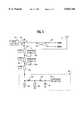
- FIG. 5is a schematic view of the lightning suppression system of FIG. 1;
- FIG. 6is a schematic showing of an assemblage including a tower mounted antenna, other tower mounted components and the lightning suppression system of FIG. 1.
- a tower mounted antenna system employing the lightning suppression system 10 of the present inventionmay desirably comprise an antenna 21, such as a conventional panel antenna, one or more amplifiers 22 and other components, such as filters 23, in a suitable housing 1.
- the lightning suppression system 10is compact relative to the other components so that it may easily be added to the antenna system housing 1 without substantially affecting the size, weight and tower mountability of the antenna system itself.
- the desired RF frequency rangeis 1850-2000 MHz. All dimensions disclosed herein are specifically determined to operate in this frequency range. For systems designed to operate in other frequency ranges, the dimensions would obviously be different.
- the housing 24is made of a conductive material, such as silver plated aluminum, and is 4.000 ⁇ 3.531 ⁇ 1.370 inches in size. Housing 24 includes cavities for various of the lightning suppression system components.
- Lightning suppression circuit 18is disposed and enclosed in suppression circuit cavity 32 and is held in place by suitable fasteners 34.
- First cylindrical capacitor 14is disposed and enclosed in first capacitor cavity 36 and second cylindrical capacitor 16 is disposed and enclosed in second capacitor cavity 38.
- Brass covers 40, 42 and 44cover cavities 32, 36 and 38, respectively.
- Cover 40is held in place by suitable fasteners 46, while covers 42 and 44 screw into threads in cavities 36 and 38, respectively.
- transmission line 20is a shielded coaxial cable and connectors 26 and 28 are standard coaxial connectors. Connectors 26 and 28 are connected together by a directional coupler 48 (see FIG. 5), comprising an elongated first conductor 50, a dielectric tube 52 and an elongated second conductor 54 (see FIG. 1).
- first conductor 50comprises a conductive rod, such as a brass rod.
- Dielectric tube 52comprises a hollow polytetrafluroethylene tube 56 having an end flange 58.
- Second conductor 54comprises a hollow conductive rod, such as a brass rod. Hollow polytetrafluroethylene tube 56 is configured to receive first conductor 50.
- the hollow second conductor 54is configured to receive-dielectric tube 52.
- first conductor 50 and second conductor 54a capacitive coupling is created between first conductor 50 and second conductor 54.
- the capacitive coupling between first conductor 50 and second conductor 54prevents direct current and low frequency signals from passing between first conductor 50 and second conductor 54, while allowing radio frequency signals to be passed therebetween.
- Connector 26is connected to the base station 43 with directional coupler 48 allowing low power direct current to flow from the base station 43 to the tower mounted amplifier 22.
- Connector 28is connected to the antenna 21 with directional coupler 48.
- the diameters of first conductor 50, second conductor 54, dielectric tube 52 and the ground conductorare predetermined so as to provide impedance matching between lightning suppression system 10 and transmission line 20.
- First cylindrical capacitor 14comprises an inner conductor element 60, an outer conductive tube 62 and a dielectric sleeve 64.
- Inner conductor element 60comprises a conventional conductor, such as 12-gage copper wire.
- Outer conductive tube 62comprises a hollow tube made of conductive material, such as silver plated aluminum, having an open end 66 and a closed end 68.
- dielectric sleeve 64is made of a dielectric material, such as polytetrafluroethylene, which is resistant to high temperatures and to high voltages.
- Inner conductor element 60is positioned inside of outer conductive tube 62 and is electrically connected, such as by solder, to outer conductive tube 62 at closed end 68. Air fills the space between inner conductor element 60 and outer conductive tube 62. Dielectric sleeve 64 surrounds outer conductive tube 62 extending past both ends 66 and 68. Inner conductor element 60 and outer conductive tube 62 are each approximately a quarter-wavelength in length.
- first cylindrical capacitor 14is 2.067 inches in length
- outer conductive tube 62is 1.299 inches in length and 0.353 inches in diameter
- dielectric sleeve 64extends 0.157 inches past each end of outer conductive tube 62 and inner conductor element 60 extends 0.275 inches from closed end 68.
- quarter-wavelength stub 12comprises an extension of inner conductor element 60.
- the extensionis in the form of a helicoidal section which electrically connects first cylindrical capacitor 14 to first conductor 50.
- the helicoidal sectionis 0.630 inches in length and comprises a single turn 0.236 inches in length and 0.43 inches in diameter. The helicoidal section both assists in providing a compact suppression system and functions as an inductance in the low pass filter.
- Second cylindrical capacitor 16comprises an inner conductor element 70, an outer conductive tube 72 and a dielectric sleeve 74.
- Inner conductor element 70comprises a conventional conductor, such as 12-gage copper wire.
- Outer conductive element 72comprises a hollow tube made of conductive material, such as silver plated aluminum, having an open end 76 and a closed end 78.
- dielectric sleeve 74is made of a dielectric material, such as polytetrafluroethylene, which is resistant to high temperatures and to high voltages.
- Inner conductor element 70is positioned inside of outer conductive tube 72 and is electrically connected, such as by solder, to outer conductive tube 72 at closed end 78. Air fills the space between inner conductor element 70 and outer conductive tube 72. Dielectric sleeve 74 surrounds outer conductive tube 72 extending past both ends 76 and 78. Inner conductor element 70 and outer conductive tube 72 are each approximately a quarter-wavelength in length.
- second cylindrical capacitor 16is 2.067 inches in length
- outer conductive tube 72is 1.299 inches in length and 0.353 inches in diameter
- dielectric sleeve 74extends 0.157 inches past each end of outer conductive tube 72 and inner conductor element 70 extends 0.275 inches from closed end 78.
- Second cylindrical capacitor 16is connected to first cylindrical capacitor 14 in series via conductor solder clip 80.
- Inner conductor element 72 of second cylindrical capacitor 16is connected to inner conductor element 62 of first cylindrical capacitor 14 such that second cylindrical capacitor 16 is positioned substantially perpendicular to first cylindrical capacitor 14 in housing 24.
- Conductor solder clip 80is placed inside housing 24 via solder clip opening 82, which is covered by solder clip cover 84.
- Lightning suppression circuit 18is electrically connected to inner conductor element 70 of second cylindrical capacitor 16 on an end opposite the connection to first cylindrical capacitor 14.
- lightning suppression circuit 18comprises a gas discharge tube 86, an inductor element 88, a varistor 90, a resistor element 92 and a zener diode 94.
- Gas discharge tube 86 and inductor element 88are connected to second cylindrical capacitor 16.
- Varistor 90 and resistor element 92are connected to inductor element 88.
- Zener diode 94 and amplifier 22are connected to resistor element 92.
- Other prior art lightning suppression circuitsmay be used as well.
- Each cylindrical capacitor 14 and 16 of the present inventionactually comprises a capacitor within a capacitor. Both a high-impedance, series RF, open-circuit section and a low impedance, RF open-circuited section can be realized by a single cylindrical capacitor.
- a high-impedance, series RF, open-circuit section and a low impedance, RF open-circuited sectioncan be realized by a single cylindrical capacitor.
- the design and packaging of the lightning suppression system 10 of the present inventionallows it to be integrated into an antenna system with a minimum number of connectors and solder joints. Furthermore, both the first cylindrical capacitor 14 and the second cylindrical capacitor 16 use conductors having a relatively large diameter, such as 12-gage copper wire. Thus, the lightning suppression system 10 of the present invention has an extremely low insertion loss providing performance improvements over prior art lightning suppression systems.
Landscapes
- Control Of Motors That Do Not Use Commutators (AREA)
Abstract
Description
Claims (23)
Priority Applications (1)
| Application Number | Priority Date | Filing Date | Title |
|---|---|---|---|
| US08/925,696US5844766A (en) | 1997-09-09 | 1997-09-09 | Lightning supression system for tower mounted antenna systems |
Applications Claiming Priority (1)
| Application Number | Priority Date | Filing Date | Title |
|---|---|---|---|
| US08/925,696US5844766A (en) | 1997-09-09 | 1997-09-09 | Lightning supression system for tower mounted antenna systems |
Publications (1)
| Publication Number | Publication Date |
|---|---|
| US5844766Atrue US5844766A (en) | 1998-12-01 |
Family
ID=25452103
Family Applications (1)
| Application Number | Title | Priority Date | Filing Date |
|---|---|---|---|
| US08/925,696Expired - LifetimeUS5844766A (en) | 1997-09-09 | 1997-09-09 | Lightning supression system for tower mounted antenna systems |
Country Status (1)
| Country | Link |
|---|---|
| US (1) | US5844766A (en) |
Cited By (46)
| Publication number | Priority date | Publication date | Assignee | Title |
|---|---|---|---|---|
| DE19845281A1 (en)* | 1998-10-01 | 2000-04-13 | Kathrein Werke Kg | High frequency amplifier circuit with overvoltage protection arrangement, has transistor protection circuit after overvoltage protection tapping with normally off transistors |
| US6064448A (en)* | 1998-05-13 | 2000-05-16 | Long Well Electronics Corp. | Induced AC power sources video amplifier |
| US6266224B1 (en)* | 1998-08-06 | 2001-07-24 | Spinner Gmbh Elektrotechnische Fabrik | Broadband coaxial overvoltage protector |
| EP1239541A1 (en)* | 2001-03-09 | 2002-09-11 | Thales | Lightning protection printed circuit and method for its manufacture |
| US20030043524A1 (en)* | 2001-09-06 | 2003-03-06 | Ntt Docomo Kyushu, Inc. | Communication line surge protecting system |
| WO2003069730A1 (en)* | 2002-02-13 | 2003-08-21 | Siemens Mobile Communications S.P.A. | Protection device for radio frequency communication lines against over voltage due to lightning |
| US6674626B2 (en) | 2001-05-15 | 2004-01-06 | William J. Fowler | Lightning suppression system for T1 and DSL circuits |
| US6677517B2 (en) | 2001-05-15 | 2004-01-13 | William J. Fowler | Lightning suppression system for power lines |
| US6683772B2 (en) | 2001-05-15 | 2004-01-27 | William J. Fowler | Lightning suppression apparatus for use with coaxial cable and heliaxial cable |
| US6690562B2 (en) | 2001-05-15 | 2004-02-10 | William J. Fowler | Lighting suppression system for control or instrumentation cable |
| EP1303004A3 (en)* | 2001-10-12 | 2004-10-06 | Polyphaser Corporation | Rf surge protection device |
| WO2004097979A1 (en)* | 2003-05-02 | 2004-11-11 | Lgp Allgon Ab | Microwave transmission unit including lightning protection |
| EP1854166A2 (en)* | 2004-10-19 | 2007-11-14 | Powerwave Technologies Sweden AB | A dc extracting arrangement |
| EP1885016A1 (en)* | 2006-07-27 | 2008-02-06 | Huber+Suhner AG | Overvoltage protection for a coax cable |
| US20080170346A1 (en)* | 2007-01-17 | 2008-07-17 | Andrew Corporation | Folded Surface Capacitor In-line Assembly |
| US20090103226A1 (en)* | 2007-10-18 | 2009-04-23 | Polyphaser Corporation | Surge suppression device having one or more rings |
| US20090109584A1 (en)* | 2007-10-30 | 2009-04-30 | Polyphaser Corporation | Surge protection circuit for passing dc and rf signals |
| US20090251840A1 (en)* | 2008-04-08 | 2009-10-08 | John Mezzalingua Associates, Inc. | Quarter wave stub surge suppressor with coupled pins |
| US20090296296A1 (en)* | 2008-05-23 | 2009-12-03 | Poshman Goeran | Surge protection arrangement |
| DE102010060581A1 (en)* | 2010-11-16 | 2012-05-16 | Telefunken Radio Communication Systems Gmbh & Co. Kg | Circuit for protecting high frequency electrical or electronic components of e.g. wireless local area network apparatus against over voltage, has short circuit branch lines galvanically secured against ground potential |
| US8400760B2 (en) | 2009-12-28 | 2013-03-19 | Transtector Systems, Inc. | Power distribution device |
| US8432693B2 (en) | 2010-05-04 | 2013-04-30 | Transtector Systems, Inc. | High power band pass RF filter having a gas tube for surge suppression |
| US8441795B2 (en) | 2010-05-04 | 2013-05-14 | Transtector Systems, Inc. | High power band pass RF filter having a gas tube for surge suppression |
| US8456791B2 (en) | 2009-10-02 | 2013-06-04 | Transtector Systems, Inc. | RF coaxial surge protectors with non-linear protection devices |
| US8599528B2 (en) | 2008-05-19 | 2013-12-03 | Transtector Systems, Inc. | DC and RF pass broadband surge suppressor |
| US8611062B2 (en) | 2010-05-13 | 2013-12-17 | Transtector Systems, Inc. | Surge current sensor and surge protection system including the same |
| US8730637B2 (en) | 2010-12-17 | 2014-05-20 | Transtector Systems, Inc. | Surge protection devices that fail as an open circuit |
| US8730640B2 (en) | 2010-05-11 | 2014-05-20 | Transtector Systems, Inc. | DC pass RF protector having a surge suppression module |
| US8976500B2 (en) | 2010-05-26 | 2015-03-10 | Transtector Systems, Inc. | DC block RF coaxial devices |
| CN104577271A (en)* | 2013-10-22 | 2015-04-29 | 芯迪半导体科技(上海)有限公司 | Surge protection circuit |
| US9048662B2 (en) | 2012-03-19 | 2015-06-02 | Transtector Systems, Inc. | DC power surge protector |
| US9054514B2 (en) | 2012-02-10 | 2015-06-09 | Transtector Systems, Inc. | Reduced let through voltage transient protection or suppression circuit |
| US9124093B2 (en) | 2012-09-21 | 2015-09-01 | Transtector Systems, Inc. | Rail surge voltage protector with fail disconnect |
| US9190837B2 (en) | 2012-05-03 | 2015-11-17 | Transtector Systems, Inc. | Rigid flex electromagnetic pulse protection device |
| WO2017032879A1 (en)* | 2015-08-27 | 2017-03-02 | Kathrein Mobilcom Austria Gmbh | Hf cavity filter with a bypass line for low-frequency signals and voltages |
| US9924609B2 (en) | 2015-07-24 | 2018-03-20 | Transtector Systems, Inc. | Modular protection cabinet with flexible backplane |
| US9991697B1 (en) | 2016-12-06 | 2018-06-05 | Transtector Systems, Inc. | Fail open or fail short surge protector |
| US10129993B2 (en) | 2015-06-09 | 2018-11-13 | Transtector Systems, Inc. | Sealed enclosure for protecting electronics |
| US10193335B2 (en) | 2015-10-27 | 2019-01-29 | Transtector Systems, Inc. | Radio frequency surge protector with matched piston-cylinder cavity shape |
| US10309906B2 (en) | 2013-09-30 | 2019-06-04 | Ademco Inc. | Low-powered system for driving a fuel control mechanism |
| US10356928B2 (en) | 2015-07-24 | 2019-07-16 | Transtector Systems, Inc. | Modular protection cabinet with flexible backplane |
| CN110400667A (en)* | 2018-04-24 | 2019-11-01 | 成都铁达电子股份有限公司 | A kind of low natural capacity piezoresistor |
| US10588236B2 (en) | 2015-07-24 | 2020-03-10 | Transtector Systems, Inc. | Modular protection cabinet with flexible backplane |
| EP3696907A1 (en)* | 2019-02-15 | 2020-08-19 | Schneider Electric Industries SAS | Radiofrequency transmission line, device comprising such a transmission line and system for monitoring and installation comprising such a device |
| CN111786082A (en)* | 2020-06-19 | 2020-10-16 | 深圳国人通信技术服务有限公司 | Miniaturized 5G basic station |
| EP4401235A4 (en)* | 2021-09-29 | 2024-12-04 | Huawei Technologies Co., Ltd. | Filter, remote radio unit and base station |
Citations (1)
| Publication number | Priority date | Publication date | Assignee | Title |
|---|---|---|---|---|
| US4985800A (en)* | 1989-10-30 | 1991-01-15 | Feldman Nathan W | Lighting protection apparatus for RF equipment and the like |
- 1997
- 1997-09-09USUS08/925,696patent/US5844766A/ennot_activeExpired - Lifetime
Patent Citations (1)
| Publication number | Priority date | Publication date | Assignee | Title |
|---|---|---|---|---|
| US4985800A (en)* | 1989-10-30 | 1991-01-15 | Feldman Nathan W | Lighting protection apparatus for RF equipment and the like |
Cited By (64)
| Publication number | Priority date | Publication date | Assignee | Title |
|---|---|---|---|---|
| US6064448A (en)* | 1998-05-13 | 2000-05-16 | Long Well Electronics Corp. | Induced AC power sources video amplifier |
| US6266224B1 (en)* | 1998-08-06 | 2001-07-24 | Spinner Gmbh Elektrotechnische Fabrik | Broadband coaxial overvoltage protector |
| DE19845281C2 (en)* | 1998-10-01 | 2002-03-28 | Kathrein Werke Kg | Amplifier circuit with overvoltage protection device |
| DE19845281A1 (en)* | 1998-10-01 | 2000-04-13 | Kathrein Werke Kg | High frequency amplifier circuit with overvoltage protection arrangement, has transistor protection circuit after overvoltage protection tapping with normally off transistors |
| US6977802B2 (en) | 2001-03-09 | 2005-12-20 | Thales | Etched circuit for lighting protection |
| EP1239541A1 (en)* | 2001-03-09 | 2002-09-11 | Thales | Lightning protection printed circuit and method for its manufacture |
| FR2821993A1 (en)* | 2001-03-09 | 2002-09-13 | Thomson Csf | LIGHTNING LIGHTNING PROTECTION CIRCUIT |
| US20020180382A1 (en)* | 2001-03-09 | 2002-12-05 | Thales | Etched circuit for lightning protection |
| US6690562B2 (en) | 2001-05-15 | 2004-02-10 | William J. Fowler | Lighting suppression system for control or instrumentation cable |
| US6674626B2 (en) | 2001-05-15 | 2004-01-06 | William J. Fowler | Lightning suppression system for T1 and DSL circuits |
| US6677517B2 (en) | 2001-05-15 | 2004-01-13 | William J. Fowler | Lightning suppression system for power lines |
| US6683772B2 (en) | 2001-05-15 | 2004-01-27 | William J. Fowler | Lightning suppression apparatus for use with coaxial cable and heliaxial cable |
| US6791813B2 (en)* | 2001-09-06 | 2004-09-14 | Ntt Docomo Kyushu, Inc. | Communication line surge protecting system |
| US20030043524A1 (en)* | 2001-09-06 | 2003-03-06 | Ntt Docomo Kyushu, Inc. | Communication line surge protecting system |
| EP1303004A3 (en)* | 2001-10-12 | 2004-10-06 | Polyphaser Corporation | Rf surge protection device |
| WO2003069730A1 (en)* | 2002-02-13 | 2003-08-21 | Siemens Mobile Communications S.P.A. | Protection device for radio frequency communication lines against over voltage due to lightning |
| US7471172B2 (en) | 2003-05-02 | 2008-12-30 | Lgp Allgon Ab | Microwave transmission unit including lightning protection |
| WO2004097979A1 (en)* | 2003-05-02 | 2004-11-11 | Lgp Allgon Ab | Microwave transmission unit including lightning protection |
| US20070053129A1 (en)* | 2003-05-02 | 2007-03-08 | Lgp Allgon Ab | Microwave transmission unit including lightning protection |
| EP1854166A2 (en)* | 2004-10-19 | 2007-11-14 | Powerwave Technologies Sweden AB | A dc extracting arrangement |
| EP1885016A1 (en)* | 2006-07-27 | 2008-02-06 | Huber+Suhner AG | Overvoltage protection for a coax cable |
| US20080049368A1 (en)* | 2006-07-27 | 2008-02-28 | Huberag | Overvoltage protection for a coaxial connector |
| US20080170346A1 (en)* | 2007-01-17 | 2008-07-17 | Andrew Corporation | Folded Surface Capacitor In-line Assembly |
| US8174132B2 (en) | 2007-01-17 | 2012-05-08 | Andrew Llc | Folded surface capacitor in-line assembly |
| US8027136B2 (en) | 2007-10-18 | 2011-09-27 | Transtector Systems, Inc. | Surge suppression device having one or more rings |
| US20090103226A1 (en)* | 2007-10-18 | 2009-04-23 | Polyphaser Corporation | Surge suppression device having one or more rings |
| US8553386B2 (en) | 2007-10-18 | 2013-10-08 | Transtector Systems, Inc. | Surge suppression device having one or more rings |
| US20090109584A1 (en)* | 2007-10-30 | 2009-04-30 | Polyphaser Corporation | Surge protection circuit for passing dc and rf signals |
| US7944670B2 (en) | 2007-10-30 | 2011-05-17 | Transtector Systems, Inc. | Surge protection circuit for passing DC and RF signals |
| US8179656B2 (en) | 2007-10-30 | 2012-05-15 | Transtector Systems, Inc. | Surge protection circuit for passing DC and RF signals |
| US8134818B2 (en) | 2008-04-08 | 2012-03-13 | John Mezzalingua Associates, Inc. | Quarter wave stub surge suppressor with coupled pins |
| US20090251840A1 (en)* | 2008-04-08 | 2009-10-08 | John Mezzalingua Associates, Inc. | Quarter wave stub surge suppressor with coupled pins |
| US8599528B2 (en) | 2008-05-19 | 2013-12-03 | Transtector Systems, Inc. | DC and RF pass broadband surge suppressor |
| US20090296296A1 (en)* | 2008-05-23 | 2009-12-03 | Poshman Goeran | Surge protection arrangement |
| US8854785B2 (en) | 2008-05-23 | 2014-10-07 | Powerwave Technologies S.A.R.L. | Surge protection arrangement |
| US8456791B2 (en) | 2009-10-02 | 2013-06-04 | Transtector Systems, Inc. | RF coaxial surge protectors with non-linear protection devices |
| US8400760B2 (en) | 2009-12-28 | 2013-03-19 | Transtector Systems, Inc. | Power distribution device |
| US8432693B2 (en) | 2010-05-04 | 2013-04-30 | Transtector Systems, Inc. | High power band pass RF filter having a gas tube for surge suppression |
| US8441795B2 (en) | 2010-05-04 | 2013-05-14 | Transtector Systems, Inc. | High power band pass RF filter having a gas tube for surge suppression |
| US8730640B2 (en) | 2010-05-11 | 2014-05-20 | Transtector Systems, Inc. | DC pass RF protector having a surge suppression module |
| US8611062B2 (en) | 2010-05-13 | 2013-12-17 | Transtector Systems, Inc. | Surge current sensor and surge protection system including the same |
| US8976500B2 (en) | 2010-05-26 | 2015-03-10 | Transtector Systems, Inc. | DC block RF coaxial devices |
| DE102010060581A1 (en)* | 2010-11-16 | 2012-05-16 | Telefunken Radio Communication Systems Gmbh & Co. Kg | Circuit for protecting high frequency electrical or electronic components of e.g. wireless local area network apparatus against over voltage, has short circuit branch lines galvanically secured against ground potential |
| US8730637B2 (en) | 2010-12-17 | 2014-05-20 | Transtector Systems, Inc. | Surge protection devices that fail as an open circuit |
| US9054514B2 (en) | 2012-02-10 | 2015-06-09 | Transtector Systems, Inc. | Reduced let through voltage transient protection or suppression circuit |
| US9048662B2 (en) | 2012-03-19 | 2015-06-02 | Transtector Systems, Inc. | DC power surge protector |
| US9190837B2 (en) | 2012-05-03 | 2015-11-17 | Transtector Systems, Inc. | Rigid flex electromagnetic pulse protection device |
| US9124093B2 (en) | 2012-09-21 | 2015-09-01 | Transtector Systems, Inc. | Rail surge voltage protector with fail disconnect |
| US10309906B2 (en) | 2013-09-30 | 2019-06-04 | Ademco Inc. | Low-powered system for driving a fuel control mechanism |
| CN104577271A (en)* | 2013-10-22 | 2015-04-29 | 芯迪半导体科技(上海)有限公司 | Surge protection circuit |
| US10129993B2 (en) | 2015-06-09 | 2018-11-13 | Transtector Systems, Inc. | Sealed enclosure for protecting electronics |
| US10356928B2 (en) | 2015-07-24 | 2019-07-16 | Transtector Systems, Inc. | Modular protection cabinet with flexible backplane |
| US9924609B2 (en) | 2015-07-24 | 2018-03-20 | Transtector Systems, Inc. | Modular protection cabinet with flexible backplane |
| US10588236B2 (en) | 2015-07-24 | 2020-03-10 | Transtector Systems, Inc. | Modular protection cabinet with flexible backplane |
| WO2017032879A1 (en)* | 2015-08-27 | 2017-03-02 | Kathrein Mobilcom Austria Gmbh | Hf cavity filter with a bypass line for low-frequency signals and voltages |
| US10193335B2 (en) | 2015-10-27 | 2019-01-29 | Transtector Systems, Inc. | Radio frequency surge protector with matched piston-cylinder cavity shape |
| US9991697B1 (en) | 2016-12-06 | 2018-06-05 | Transtector Systems, Inc. | Fail open or fail short surge protector |
| CN110400667A (en)* | 2018-04-24 | 2019-11-01 | 成都铁达电子股份有限公司 | A kind of low natural capacity piezoresistor |
| CN110400667B (en)* | 2018-04-24 | 2021-07-13 | 成都铁达电子股份有限公司 | Low-inherent-capacitance piezoresistor |
| EP3696907A1 (en)* | 2019-02-15 | 2020-08-19 | Schneider Electric Industries SAS | Radiofrequency transmission line, device comprising such a transmission line and system for monitoring and installation comprising such a device |
| FR3092944A1 (en)* | 2019-02-15 | 2020-08-21 | Schneider Electric Industries Sas | Radiofrequency transmission line, device comprising such a transmission line and a system for monitoring an installation comprising such a device |
| US11223097B2 (en) | 2019-02-15 | 2022-01-11 | Schneider Electric Industries Sas | Radiofrequency transmission line, device including such a transmission line and system for monitoring an installation including such a device |
| CN111786082A (en)* | 2020-06-19 | 2020-10-16 | 深圳国人通信技术服务有限公司 | Miniaturized 5G basic station |
| EP4401235A4 (en)* | 2021-09-29 | 2024-12-04 | Huawei Technologies Co., Ltd. | Filter, remote radio unit and base station |
Similar Documents
| Publication | Publication Date | Title |
|---|---|---|
| US5844766A (en) | Lightning supression system for tower mounted antenna systems | |
| US6944005B2 (en) | Surge protected coaxial termination | |
| US7349191B2 (en) | Offset planar coil coaxial surge suppressor | |
| US7564669B2 (en) | Protective device | |
| US4748450A (en) | Vehicular multiband antenna feedline coupling device | |
| US5953195A (en) | Coaxial protector | |
| US4985800A (en) | Lighting protection apparatus for RF equipment and the like | |
| EP2088652B1 (en) | Low bypass fine arrestor | |
| US6754060B2 (en) | Protective device | |
| US6456478B1 (en) | Broad-band EMP surge diverter | |
| EP1137095B1 (en) | Broadband shorted stub surge protector | |
| US7092230B2 (en) | Interference filter and lightning conductor device | |
| EP1780840A2 (en) | Tuned coil coaxial surge suppressor | |
| US6677833B2 (en) | Multilayered band separator with grounding parasitic capacitor | |
| KR20030060919A (en) | Surge protection filter and lightning conductor system | |
| US8854153B2 (en) | Device for transmitting electromagnetic signals | |
| US6636407B1 (en) | Broadband surge protector for RF/DC carrying conductor | |
| US5412393A (en) | Retractable antenna assembly with bottom connector | |
| US20030189526A1 (en) | Low loss loading, compact antenna and antenna loading method | |
| US5668557A (en) | Surface-mount antenna and communication device using same | |
| EP1772931A2 (en) | Multiple planar inductor coaxial surge suppressor | |
| US5764114A (en) | EMP-filter in a coaxial line | |
| US5745328A (en) | Electromagnetic impulse suppression curcuit | |
| CN1201273A (en) | Antenna device suitable to mobile radio equipments | |
| US6873225B2 (en) | Diplexers with low pass filter having distributed and non-distributed (lumped) elements |
Legal Events
| Date | Code | Title | Description |
|---|---|---|---|
| AS | Assignment | Owner name:FOREM S.P.A., ITALY Free format text:ASSIGNMENT OF ASSIGNORS INTEREST;ASSIGNOR:MIGLIOLI, LORENZO;REEL/FRAME:008779/0124 Effective date:19970903 Owner name:FOREM S.P.A., ITALY Free format text:ASSIGNMENT OF ASSIGNORS INTEREST;ASSIGNOR:MIGLIOLI, LORENZO;REEL/FRAME:008794/0840 Effective date:19970903 | |
| AS | Assignment | Owner name:FOREM S.R.L., ITALY Free format text:ASSIGNMENT OF ASSIGNORS INTEREST;ASSIGNORS:D'ORO, SILVIA CAVALIERI;RIVOLTA, MASSIMO;REEL/FRAME:009383/0478 Effective date:19980513 | |
| STCF | Information on status: patent grant | Free format text:PATENTED CASE | |
| CC | Certificate of correction | ||
| FEPP | Fee payment procedure | Free format text:PAYOR NUMBER ASSIGNED (ORIGINAL EVENT CODE: ASPN); ENTITY STATUS OF PATENT OWNER: LARGE ENTITY | |
| AS | Assignment | Owner name:KEYBANK NATIONAL ASSOCIATION, OHIO Free format text:SECURITY AGREEMENT;ASSIGNOR:ALLEN TELECOM, INC.;REEL/FRAME:015017/0844 Effective date:20020131 | |
| AS | Assignment | Owner name:KEYBANK NATIONAL ASSOCIATION, OHIO Free format text:SECURITY INTEREST;ASSIGNOR:ALLEN TELECOM, INC.;REEL/FRAME:012822/0425 Effective date:20020131 | |
| FPAY | Fee payment | Year of fee payment:4 | |
| AS | Assignment | Owner name:ALLEN TELECOM INC., OHIO Free format text:RELEASE OF SECURITY INTEREST;ASSIGNOR:KEYBANK NATIONAL ASSOCIATION, AS COLLATERAL AGENT;REEL/FRAME:015027/0518 Effective date:20030716 | |
| FPAY | Fee payment | Year of fee payment:8 | |
| FPAY | Fee payment | Year of fee payment:12 | |
| AS | Assignment | Owner name:JPMORGAN CHASE BANK, N.A., AS COLLATERAL AGENT, NE Free format text:SECURITY AGREEMENT;ASSIGNORS:ALLEN TELECOM LLC, A DELAWARE LLC;ANDREW LLC, A DELAWARE LLC;COMMSCOPE, INC. OF NORTH CAROLINA, A NORTH CAROLINA CORPORATION;REEL/FRAME:026276/0363 Effective date:20110114 | |
| AS | Assignment | Owner name:JPMORGAN CHASE BANK, N.A., AS COLLATERAL AGENT, NE Free format text:SECURITY AGREEMENT;ASSIGNORS:ALLEN TELECOM LLC, A DELAWARE LLC;ANDREW LLC, A DELAWARE LLC;COMMSCOPE, INC OF NORTH CAROLINA, A NORTH CAROLINA CORPORATION;REEL/FRAME:026272/0543 Effective date:20110114 | |
| AS | Assignment | Owner name:WILMINGTON TRUST, NATIONAL ASSOCIATION, AS COLLATERAL AGENT, CONNECTICUT Free format text:SECURITY INTEREST;ASSIGNORS:ALLEN TELECOM LLC;COMMSCOPE TECHNOLOGIES LLC;COMMSCOPE, INC. OF NORTH CAROLINA;AND OTHERS;REEL/FRAME:036201/0283 Effective date:20150611 Owner name:WILMINGTON TRUST, NATIONAL ASSOCIATION, AS COLLATE Free format text:SECURITY INTEREST;ASSIGNORS:ALLEN TELECOM LLC;COMMSCOPE TECHNOLOGIES LLC;COMMSCOPE, INC. OF NORTH CAROLINA;AND OTHERS;REEL/FRAME:036201/0283 Effective date:20150611 | |
| AS | Assignment | Owner name:REDWOOD SYSTEMS, INC., NORTH CAROLINA Free format text:RELEASE OF SECURITY INTEREST PATENTS (RELEASES RF 036201/0283);ASSIGNOR:WILMINGTON TRUST, NATIONAL ASSOCIATION;REEL/FRAME:042126/0434 Effective date:20170317 Owner name:COMMSCOPE TECHNOLOGIES LLC, NORTH CAROLINA Free format text:RELEASE OF SECURITY INTEREST PATENTS (RELEASES RF 036201/0283);ASSIGNOR:WILMINGTON TRUST, NATIONAL ASSOCIATION;REEL/FRAME:042126/0434 Effective date:20170317 Owner name:COMMSCOPE, INC. OF NORTH CAROLINA, NORTH CAROLINA Free format text:RELEASE OF SECURITY INTEREST PATENTS (RELEASES RF 036201/0283);ASSIGNOR:WILMINGTON TRUST, NATIONAL ASSOCIATION;REEL/FRAME:042126/0434 Effective date:20170317 Owner name:ALLEN TELECOM LLC, NORTH CAROLINA Free format text:RELEASE OF SECURITY INTEREST PATENTS (RELEASES RF 036201/0283);ASSIGNOR:WILMINGTON TRUST, NATIONAL ASSOCIATION;REEL/FRAME:042126/0434 Effective date:20170317 | |
| AS | Assignment | Owner name:REDWOOD SYSTEMS, INC., NORTH CAROLINA Free format text:RELEASE BY SECURED PARTY;ASSIGNOR:JPMORGAN CHASE BANK, N.A.;REEL/FRAME:048840/0001 Effective date:20190404 Owner name:COMMSCOPE TECHNOLOGIES LLC, NORTH CAROLINA Free format text:RELEASE BY SECURED PARTY;ASSIGNOR:JPMORGAN CHASE BANK, N.A.;REEL/FRAME:048840/0001 Effective date:20190404 Owner name:COMMSCOPE, INC. OF NORTH CAROLINA, NORTH CAROLINA Free format text:RELEASE BY SECURED PARTY;ASSIGNOR:JPMORGAN CHASE BANK, N.A.;REEL/FRAME:048840/0001 Effective date:20190404 Owner name:ANDREW LLC, NORTH CAROLINA Free format text:RELEASE BY SECURED PARTY;ASSIGNOR:JPMORGAN CHASE BANK, N.A.;REEL/FRAME:048840/0001 Effective date:20190404 Owner name:ALLEN TELECOM LLC, ILLINOIS Free format text:RELEASE BY SECURED PARTY;ASSIGNOR:JPMORGAN CHASE BANK, N.A.;REEL/FRAME:048840/0001 Effective date:20190404 Owner name:COMMSCOPE, INC. OF NORTH CAROLINA, NORTH CAROLINA Free format text:RELEASE BY SECURED PARTY;ASSIGNOR:JPMORGAN CHASE BANK, N.A.;REEL/FRAME:049260/0001 Effective date:20190404 Owner name:ANDREW LLC, NORTH CAROLINA Free format text:RELEASE BY SECURED PARTY;ASSIGNOR:JPMORGAN CHASE BANK, N.A.;REEL/FRAME:049260/0001 Effective date:20190404 Owner name:ALLEN TELECOM LLC, ILLINOIS Free format text:RELEASE BY SECURED PARTY;ASSIGNOR:JPMORGAN CHASE BANK, N.A.;REEL/FRAME:049260/0001 Effective date:20190404 Owner name:COMMSCOPE TECHNOLOGIES LLC, NORTH CAROLINA Free format text:RELEASE BY SECURED PARTY;ASSIGNOR:JPMORGAN CHASE BANK, N.A.;REEL/FRAME:049260/0001 Effective date:20190404 Owner name:REDWOOD SYSTEMS, INC., NORTH CAROLINA Free format text:RELEASE BY SECURED PARTY;ASSIGNOR:JPMORGAN CHASE BANK, N.A.;REEL/FRAME:049260/0001 Effective date:20190404 |