US5844521A - Geolocation method and apparatus for satellite based telecommunications system - Google Patents
Geolocation method and apparatus for satellite based telecommunications systemDownload PDFInfo
- Publication number
- US5844521A US5844521AUS08/758,871US75887196AUS5844521AUS 5844521 AUS5844521 AUS 5844521AUS 75887196 AUS75887196 AUS 75887196AUS 5844521 AUS5844521 AUS 5844521A
- Authority
- US
- United States
- Prior art keywords
- mobile terminal
- frequency
- timing
- differential
- synchronization
- Prior art date
- Legal status (The legal status is an assumption and is not a legal conclusion. Google has not performed a legal analysis and makes no representation as to the accuracy of the status listed.)
- Expired - Lifetime
Links
- 238000000034methodMethods0.000titleclaimsabstractdescription51
- 230000006854communicationEffects0.000claimsabstractdescription101
- 238000004891communicationMethods0.000claimsabstractdescription101
- 230000001360synchronised effectEffects0.000claimsdescription17
- 230000033001locomotionEffects0.000description29
- 238000005259measurementMethods0.000description16
- 230000000875corresponding effectEffects0.000description14
- 238000012937correctionMethods0.000description8
- 230000005540biological transmissionEffects0.000description7
- 238000010586diagramMethods0.000description5
- 230000011664signalingEffects0.000description5
- 230000000694effectsEffects0.000description4
- 230000000977initiatory effectEffects0.000description4
- 102100034274Diamine acetyltransferase 1Human genes0.000description3
- 101000641077Homo sapiens Diamine acetyltransferase 1Proteins0.000description3
- 101000713305Homo sapiens Sodium-coupled neutral amino acid transporter 1Proteins0.000description3
- 238000006243chemical reactionMethods0.000description3
- 230000001419dependent effectEffects0.000description3
- 238000012986modificationMethods0.000description3
- 230000004048modificationEffects0.000description3
- 230000007175bidirectional communicationEffects0.000description2
- 238000012545processingMethods0.000description2
- 238000001228spectrumMethods0.000description2
- 101000640813Homo sapiens Sodium-coupled neutral amino acid transporter 2Proteins0.000description1
- 101000716973Homo sapiens Thialysine N-epsilon-acetyltransferaseProteins0.000description1
- 102100020926Thialysine N-epsilon-acetyltransferaseHuman genes0.000description1
- 230000015556catabolic processEffects0.000description1
- 230000001413cellular effectEffects0.000description1
- 230000001427coherent effectEffects0.000description1
- 230000002596correlated effectEffects0.000description1
- 238000006731degradation reactionMethods0.000description1
- 238000011161developmentMethods0.000description1
- 230000009977dual effectEffects0.000description1
- 230000008030eliminationEffects0.000description1
- 238000003379elimination reactionMethods0.000description1
- 238000010237hybrid techniqueMethods0.000description1
- 238000011160researchMethods0.000description1
Images


Classifications
- H—ELECTRICITY
- H04—ELECTRIC COMMUNICATION TECHNIQUE
- H04B—TRANSMISSION
- H04B7/00—Radio transmission systems, i.e. using radiation field
- H04B7/14—Relay systems
- H04B7/15—Active relay systems
- H04B7/185—Space-based or airborne stations; Stations for satellite systems
- H04B7/1853—Satellite systems for providing telephony service to a mobile station, i.e. mobile satellite service
- H04B7/18545—Arrangements for managing station mobility, i.e. for station registration or localisation
- H04B7/18547—Arrangements for managing station mobility, i.e. for station registration or localisation for geolocalisation of a station
- H04B7/1855—Arrangements for managing station mobility, i.e. for station registration or localisation for geolocalisation of a station using a telephonic control signal, e.g. propagation delay variation, Doppler frequency variation, power variation, beam identification
- G—PHYSICS
- G01—MEASURING; TESTING
- G01S—RADIO DIRECTION-FINDING; RADIO NAVIGATION; DETERMINING DISTANCE OR VELOCITY BY USE OF RADIO WAVES; LOCATING OR PRESENCE-DETECTING BY USE OF THE REFLECTION OR RERADIATION OF RADIO WAVES; ANALOGOUS ARRANGEMENTS USING OTHER WAVES
- G01S5/00—Position-fixing by co-ordinating two or more direction or position line determinations; Position-fixing by co-ordinating two or more distance determinations
- G01S5/02—Position-fixing by co-ordinating two or more direction or position line determinations; Position-fixing by co-ordinating two or more distance determinations using radio waves
- G01S5/12—Position-fixing by co-ordinating two or more direction or position line determinations; Position-fixing by co-ordinating two or more distance determinations using radio waves by co-ordinating position lines of different shape, e.g. hyperbolic, circular, elliptical or radial
- H—ELECTRICITY
- H04—ELECTRIC COMMUNICATION TECHNIQUE
- H04W—WIRELESS COMMUNICATION NETWORKS
- H04W64/00—Locating users or terminals or network equipment for network management purposes, e.g. mobility management
- H04W64/003—Locating users or terminals or network equipment for network management purposes, e.g. mobility management locating network equipment
- H—ELECTRICITY
- H04—ELECTRIC COMMUNICATION TECHNIQUE
- H04W—WIRELESS COMMUNICATION NETWORKS
- H04W84/00—Network topologies
- H04W84/02—Hierarchically pre-organised networks, e.g. paging networks, cellular networks, WLAN [Wireless Local Area Network] or WLL [Wireless Local Loop]
- H04W84/04—Large scale networks; Deep hierarchical networks
- H04W84/06—Airborne or Satellite Networks
Definitions
- the present applicationrelates to co-pending application "GEOLOCATION METHOD AND APPARATUS FOR SATELLITE BASED TELECOMMUNICATION SYSTEM", filed Apr. 24, 1996, Ser. No. 08/638,066, Attorney Docket No. 16-0281.
- the above co-identified application, 08/638,066,is assigned to the Assignee of the present application and expressly incorporated herein in its entirety by reference.
- the present inventiongenerally relates to a satellite based telecommunications system. More specifically, the invention relates to a method and apparatus for calculating the geolocation of user terminals based on information within the communications signal.
- Satellite based telecommunications systemssuch as Odyssey (as proposed by the assignee of the present application), utilize a constellation of satellites to relay communications signals between user terminals and earth or base stations.
- the user terminalsare assigned to earth stations.
- the earth stationsdirect calls to and from the assigned user terminals.
- the user terminals and associated earth stationscommunicate along preassigned communications channels having a preassigned bandwidth (subband) centered about a carrier frequency.
- Some communications systemsmay require that the location of a mobile terminal communicating through the satellite constellation be determined or verified for a number of reasons, such as to efficiently allocate network resources, to block or accept services based on mobile terminal location, to route calls to special bureaus for emergency or operator services, to effect billing dependent upon location, to direct emergency services, to provide secondary navigational services and the like.
- the location of mobile terminalsmay be determined by a satellite based navigation system.
- Satellite based navigation systemssuch as the global positioning satellite (GPS) system, include a constellation of satellites which transmit navigation signals to the user units. Each satellite emits a unique navigation signal along a preassigned navigation channel. User units obtain navigation information from multiple navigation signals and, based thereon, calculate the terminal's position relative to the earth.
- GPSglobal positioning satellite
- One GPS techniqueis explained in an article entitled “GPS Signal Structure and Performance Characteristics.” by J. J. Spilker, Jr., Global Positioning System, which is incorporated by reference in its entirety.
- a navigation terminalrequires the use of navigation measurements from at least three satellites and only affords one way communications. The GPS navigation terminals do not transmit signals to the satellites.
- ranging systemshave been suggested for tracking moving satellites from earth stations.
- One exampleis the TDRS system which performs ranging of moving satellites from a geostationary satellite.
- the TDRS systemrelies on a single two-way ranging link between a geosynchronous satellite and a low orbiting satellite to track movement of the low orbiting satellite.
- Alternative ranging systemsuse a single two-way ranging link between an earth station and a satellite to track movement of the satellite.
- these ranging systemsrequire ranging measurements to be made over a long period of time in order to ensure high accuracy and resolve position ambiguity of the moving satellite.
- these ranging systemsuse only a single tracking station or track a single satellite at any given time. Further, these ranging systems have not been applied to position determination of mobile terrestrial user terminals.
- the navigation, ranging and communications signalsare transmitted over separate, mutually exclusive channels specifically designated to carry corresponding signals. Consequently earth stations, satellites and user terminals must be designed to support separate communications and navigation channels, thereby undesirably complicating the overall system.
- Existing telecommunications systemshave not been able to merge communications and geolocation signals/data onto a single RF signal. Instead, conventional systems rely on radio signals and associated transmitters and receivers which are specifically designed and applied for position determination.
- Satellite systemshave attempted to increase the overall capacity of the available frequency subbands by utilizing a variety of user-access or "spread spectrum-based" techniques to increase the user-density within a given frequency subband.
- These user-access techniquesinclude frequency division multiple access (FDMA coding), time division multiple access (TDMA coding), and code division multiple access (CDMA coding).
- FDMA codingfrequency division multiple access
- TDMA codingtime division multiple access
- CDMA codingcode division multiple access
- hybrid techniqueshave been proposed using a combination of TDMA, FDMA and CDMA codes.
- each user terminalwhen assigned to a corresponding channel, is given a unique TDMA/FDMA/CDMA code and/or transmission timing/frequency.
- the user terminalstransmit and receive all communications signals at the assigned carrier channel, code and transmission timing/frequency.
- the above-mentioned coding techniquesrequire the communications link between a user terminal and an earth station to be adjusted or tuned continually. Such adjustments are necessary to ensure that the user terminal continues to transmit within its assigned channel as the user terminal and/or coverage satellites move relative to one another.
- User terminals and earth stationstransmit telecommunications signals as discrete packets or frames of information.
- Several of the above-mentioned coding techniquesrequire that the communications link be maintained "synchronous" between the earth station and the user terminal.
- a "synchronous" communications linkrequires that each frame of data be received (at a user terminal or an earth station) at an instant in time simultaneous with receipt of frames transmitted from other terminals and/or earth stations.
- the framesmust also be received in the assigned subband centered about an assigned carrier frequency. Thus, synchronization and subband alignment are determined with respect to the receiver.
- synchronization and subband alignmentare continuously effected 1) by variations in range between the satellites and user terminals or earth stations (e.g., propagation delay) and 2) by changes in the relative range velocity between the satellite and the user terminals or earth stations (e.g., Doppler effect).
- Propagation delay variationarises as user units and/or coverage satellites move since the distance or range changes between a user terminal and its associated earth station. Consequently, the propagation time of a frame between an earth station and user terminal changes.
- the transmittere.g., earth station or user terminal
- the transmitterretards or advances the initiating time at which data frames are transmitted.
- transmitters located near an intended receiverretard the transmission initiating time, while transmitters located far from the receiver advance the transmission initiating time.
- Doppler shift variationarises as satellites move relative to earth stations and user terminals since the resultant carrier frequency perceived at a receiver changes. For instance, when a satellite moves toward a user unit, the perceived carrier frequency at the satellite (and at the subsequent earth station) of a communications signal is greater than the actual carrier frequency at which the user terminal transmitted the communications signal. Stated another way, the perceived carrier frequency at the receiver is greater than it would otherwise be if the satellite and transmitter remained at rest with respect to one another. Similarly, when the satellite moves away from the transmitter, the receiver perceives a carrier frequency which is lower than the carrier frequency which would be otherwise perceived if the satellite were not moving relative to the transmitter.
- Transmitterse.g., user terminals and earth stations
- Doppler effectadjust the carrier frequency, at which communications signals are transmitted, to account for positive and negative Doppler shifts.
- a transmitterensures that communications signals transmitted therefrom remain within the assigned channel and arrive synchronous with signals from other transmitters.
- the timing and frequencymay be controlled in several manners.
- the earth stationmay transmit timing and frequency update information to each user terminal.
- GPS-type navigation informationrequire an unduly large number of satellites.
- GPS user terminalsrequire simultaneous line-of-sight navigation links with multiple satellites. Consequently, the GPS system necessitates a constellation of satellites which ensure that multiple satellites are simultaneously viewable at each position covered by the system. This multi-satellite coverage technique unduly increases the number of satellites.
- a needremains within the industry for an improved geolocation method and apparatus for use with satellite based telecommunications. It is an object of the present invention to meet this need.
- a method for determining the geolocation of a user terminal within a telecommunications system having a constellation of satellites which relay communications signals between earth stations and user terminals over preassigned channelsachieves synchronization of the telecommunications signals by calculating timing and frequency update information for the user terminals.
- the timing and frequency update informationis also used by the earth station to calculate the geoposition of the user terminal. To do so, the earth station calculates a distance between the satellite and a user terminal based on the corresponding propagation time therebetween which is obtained from the timing information. Once the satellite to user terminal distance is obtained, a range solution line may be calculated therefrom.
- the frequency update informationis used to calculate a Doppler solution line upon which the user terminal is positioned.
- the range and Doppler solution linesare combined to obtain points of intersection therebetween. These points of intersection represent potential geolocations of the user terminal.
- the earth stationdiscriminates between these intersection points in one of several manners, such as the coverage beam spot or geographic cell assigned to the user terminal. Upon obtaining a single intersection point, the longitude and latitude of this point or output is the geolocation of the user terminal.
- An alternative methodfor determining the geolocation of a mobile terminal within a telecommunications satellite system having a constellation of satellites which relay communications signals between earth stations and mobile terminals via intermediate satellites.
- the satellite systemsupports first and second forward communications links from first and second earth stations through first and second satellites to a common mobile terminal.
- the systemfurther supports at least one terminal communications link from the mobile terminal through the first satellite to the first earth station.
- the methodincludes transmitting first and second communications signals over the first and second forward links to the mobile terminal from the first and second earth stations.
- the mobile terminalobtains synchronization differential data based on the received first and second communications signals.
- the synchronization differential datamay include timing and frequency synchronization data necessary to maintain the first and second communications signals synchronized in time and frequency at the mobile terminal.
- the mobile terminaltransmits the synchronization differential data to the first earth station over the return link.
- the first earth stationreceives communications signals from the mobile terminal and based thereon calculates return link synchronization data.
- the earth stationfurther calculates at least first and second geoposition lines, along which the mobile terminal is positioned, based on the return link synchronization data and the synchronization differential data received from the mobile terminal.
- the first and second geoposition linesdefine a point of intersection at which the mobile terminal is located.
- FIG. 1generally illustrates a perspective view of a satellite system according to the present invention.
- FIG. 2generally illustrates a top plan view of a satellite and its associated coverage footprint.
- FIG. 3generally illustrates a block diagram of an earth station according to the preferred embodiment of the present invention.
- FIG. 4generally illustrates a flow chart of the processing sequence followed by an earth station according to a preferred embodiment of the present invention.
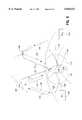
- FIG. 5generally illustrates a perspective view of an alternative satellite system according to the present invention.
- FIG. 6generally illustrates a block diagram of a subsection of the mobile terminal which calculates synchronization differential data according to an alternative embodiment of the present invention.
- FIG. 7illustrates a block diagram of a subsection of an earth station which calculates geolocation information according to an alternative embodiment of the present invention.
- FIG. 1generally illustrates a satellite based telecommunications system including a satellite 2 which relays communications signals between an earth station 4 and a user terminal 6.
- the earth station 4transmits signals to the user terminal 6 through a forward link including link sections 8 and 10.
- the user terminal 6transmits communications signals to the earth station 4 via a return link including link sections 12 and 14.
- the satellite 2functions as a "bent pipe” and passes communications received upon forward link section 8 onward to the user terminal 6 via link section 10.
- the satellite 2relays without delay signals received upon link section 12 to the earth station 4 upon return link section 14.
- the preferred embodimentmay utilize a closed loop system in which the earth station 2 transmits corrective timing and frequency error information to each corresponding user terminal to maintain a synchronous communications link therebetween. While FIG. 1 illustrates a single user terminal 6, it is understood that the preferred embodiment is useful with multiple terminals, earth stations and satellites.
- FIG. 2illustrates a footprint 16 representing the coverage area of satellite 2.
- the satellite 2forms the footprint 16 from a plurality of overlapping beam coverage spots 18.
- the footprint 16moves across the surface of the earth 24 as the satellite 2 travels in the direction indicated by arrow 20.
- the satellite 2may support communicates between the earth station 4 and user terminal 6 as long as they are located in the footprint 16.
- the satellite based telecommunications system of the preferred embodimentmay utilize several management techniques such as spread spectrum communications.
- the systemmay use code division multiple access (CDMA) coding.
- CDMAcode division multiple access
- Other coding techniquesmay be used so long as they enable multiple user stations 6 to transmit continuously and upon mutually exclusive channels.
- Such channelsmay be in the same frequency band, such as one of the frequency subbands assigned to beam spot 22.
- the potential for interferenceincreases. Interference is avoided at the earth station by identifying a unique "signature" for each user terminal and its associated communications signal.
- Each user terminalis assigned a unique signature (e.g., a unique CDMA code, TDMA code, FDMA code) for transmission within the corresponding frequency subband.
- each signaturerepresents a unique preassigned waveform or chip sequence, wherein a chip may represent a portion of a binary bit depending upon the number of user terminals assigned to the subband.
- the user terminalcombines its signature waveform with outgoing frames or packets of communications and/or command data.
- the resultant combined RF signalis transmitted at the preassigned carrier frequency.
- CDMA codingthe combination of the assigned carrier frequency and the terminal's unique CDMA code define a "channel" assigned to the particular user terminal.
- PN or CDMA codesmay be used.
- Other codesmay be used so long as the code retains a highly orthogonal characteristic. In other words, it is desirable that the code be easily distinguishable 1) from a replica of itself shifted in time and 2) from other codes used within the same subband of the telecommunications system.
- FIG. 3illustrates, in block diagram form, a configuration for the earth station 2 utilized when calculating geolocation information.
- the earth station 2includes a tracker demodulator 30 which receives an RF signal on line 32.
- the tracker demodulator 30processes the received RF signal based on stored reference signatures for user terminals assigned to the earth station.
- the tracker demodulator 30outputs communications data.
- the demodulator 30may receive multiple incoming RF signals superimposed upon one another and substantially synchronized in time with respect to a reference time. Such synchronization ensures that the signature for each user terminal's RF signal is aligned in time with one another.
- all incoming RF signalsmust be centered about the corresponding carrier frequency to minimize co-channel interference.
- the earth stationprocesses multiple RF signals from multiple user terminals, for purpose of simplification, a single RF signal from a single user terminal is explained below in connection with the geolocation process.
- the earth station 2includes timing and frequency discriminators 34 and 36 which receive an RF signal.
- the timing discriminator 34compares the incoming RF signal with a timing reference signal.
- the frequency discriminator 36compares the incoming RF signal with a frequency reference signal. Based on these comparisons, the timing and frequency discriminators 34 and 36 output timing and frequency error correction data, respectively, along lines 38 and 40.
- the timing and frequency correction dataare transmitted to the associated user terminal.
- the timing correction datamay instruct the user terminal to advance or retard the initiating time of each frame of communications data in order to synchronize the starting point of such frames with incoming frames of data from other user terminals in the same subband and/or beam coverage spot.
- the discriminator 36directs, via the frequency correction data, the user terminal to increase or decrease the transmission carrier frequency in order to ensure that the perceived carrier frequency at the earth station corresponds to the user terminal's assigned carrier frequency.
- the perceived frequency at the earth stationdoes not necessarily equal the transmitted frequency at the user terminal.
- relative motion between the user terminal and satelliteinduce "Doppler" shifts into the carrier frequency.
- the amount of Doppler shiftis dependent upon the distance between the user terminal and satellite.
- the direction of the Doppler shiftnamely positive or negative, is dependent upon the direction of travel of the satellite relative to the user terminal.
- the perceived carrier frequency at the earth station receiveris greater than the emitted carrier frequency at the user terminal transmitter.
- the perceived carrier frequency at the earth station receiveris lower than the carrier frequency emitted at the transmitter.
- the frequency correction data transmitted to the user terminalenables the user terminal to adjust its transmitter carrier frequency to ensure that the received carrier frequency corresponds to the assigned carrier frequency for the channel to which the user terminal has been assigned to maintain its communications link with the earth station.
- FIG. 2illustrates a plurality of Doppler solution lines (generally denoted by bracket 29).
- Each Doppler solution lineis associated with a specific Doppler shift value Consequently, a user terminal located anywhere along a single one of Doppler solution lines 29 will experience the same Doppler shift. Thus, an earth station receiver will perceive the same shift in carrier frequency from a user terminal located anywhere along a single Doppler solution line.
- FIG. 2also illustrates a plurality of range solution lines (generally denoted by dashed lines 51). Each range solution line is associated with a constant distance between the satellite and user terminal. Each range solution line corresponds to a unique round trip propagation time delay between the earth station, satellite and user terminal. The round trip propagation time equals the time required for an RF signal to travel along forward link sections 8 and 10 to the user terminal and back along the return link sections 12 and 14 to the earth station.
- the timing and frequency correction dataare also supplied to range and doppler line solution modules 42 and 44.
- the range and doppler line solution modules 42 and 44calculate the range line 26 and doppler solution line 28 (FIG. 1).
- the range solution module 42calculates a range solution line 26 based on the earth station to user terminal range which is calculated based on the round trip propagation time required for a communications signal to travel along the forward links 8 and 10 (FIG. 1) and return along the return links 12 and 14.
- the range between the satellite and user terminalmay be calculated since the range between the satellite and earth station is already known.
- a range solution line 26may be drawn (as shown in FIG. 1) with the satellite 2 at its center and with a radius equalling the distance between the satellite and user terminal.
- the Doppler solution line module 44may calculate the Doppler shift line 28 based on the frequency shift between the transmitted carrier frequency at the user terminal and the received carrier frequency at the earth station.
- the transmitted carrier frequencymay be calculated from stored past Doppler shift information concerning the user terminal which is updated repeatedly with the frequency error data determined in discriminator 34. Once the frequency shift is calculated, a corresponding Doppler solution line may be obtained, such as from a look-up table or through empirical techniques.
- the geolocation module 46calculates the intersections of these lines as longitudes and latitudes.
- the solution linemay represent an equation defining a circle, centered at the satellite, on which the user terminal must fall.
- the Doppler solution linemay represent an equation defining an arc centered on the axis of the satellites direction of movement.
- the linesinclude two points of intersection at points 52 and 54. The correct point of intersection may be determined based upon the carrier frequency of the beam spot covering the user terminal. As explained above, each beam spot utilizes one or more unique subband carrier frequencies. Consequently, the beam spot surrounding point 52 utilizes a carrier frequency which differs from the beam spots surrounding point 54. Based thereon, point 54 may be discarded and point 52 identified as the geolocation of the user terminal.
- FIG. 4illustrates the processing sequence carried out by the preferred embodiment of the present invention to calculate the user terminal's geolocation.
- a communications signalis received (step 200)
- auto correlationis performed (step 210).
- the received RF signalmay include a synchronization field which contains a synchronization signal that is correlated with a reference sync signal (e.g., reference signature code) to calculate the timing shift within the received RF signal from its desired start time.
- a timing error offsetis obtained from this correlation process (step 210).
- the timing offsetis combined with the prior known propagation time between the earth station and user terminal to obtain an updated overall round trip propagation time.
- a range solution line(such as line 26 in FIGS. 1 and 2) is calculated based on the satellite's current position and the distance between the satellite and user terminal. As noted above, the current satellite position and the satellite to user terminal distance serve as a center and radius, respectively, of a range solution line.
- the carrier frequency of the received communications signalis obtained.
- a frequency error offsetis calculated based on a comparison of the received carrier frequency and a reference carrier frequency. As explained above, the received and reference carrier frequencies will vary as the distance and relative velocity between the satellite and user terminal change.
- a Doppler shiftis next obtained based on the frequency offset calculated in step 220.
- a Doppler solution line(such as line 28 in FIGS. 1 and 2) is obtained based on the Doppler shift in the received signal.
- the earth stationalso considers the satellite's current position, direction of movement (as indicated by arrow 20 in FIG. 2) and velocity relative to the user terminal.
- the Doppler and range solution linesare simultaneously solved to obtain points of intersection (such as points 52 and 54 in FIG. 2).
- the points of intersectionrepresent potential geolocations of the user terminal.
- the earth stationidentifies the point of intersection (between points 52 and 54) corresponding to the user terminal. This identification may be carried out in a variety of manners. For instance, when points 52 and 54 lie within different coverage beam spots, the earth station may distinguish therebetween by determining which point of intersection lies within the coverage beam spot covering the user terminal.
- the earth stationmay identify the point of intersection corresponding to the user terminal based on the user terminal's current assigned geographic cell. Geographic cells represent fixed predefined regions upon the earth which differ from coverage beam spots.
- each user terminalmay be assigned to a particular geographic cell. In such case, the earth station would distinguish between intersection points 52 and 54 based upon the geographic cell assigned to the user terminal. As a further option, discrimination between points 52 and 54 may be effected by a process of elimination.
- This geolocation outputmay include a longitude and latitude identifying the user terminal's location.
- the above identified geolocation informationmay be used for a variety of purposes.
- the geolocationmay provide network control information necessary for call routing.
- the geolocation informationmay also be used to provide emergency location services, such as during 911 calls, to identify the position of the user terminal.
- the geolocation informationmay be used to provide navigation services, billing and call management and the like, such as between countries and companies providing and requiring different services as a function of the user terminal's location, including service restrictions.
- the code timing discriminator 34may be modified to utilize a variety of conventional synchronization routines for analyzing the incoming signal.
- the discriminator 34may utilize auto correlation through any of several known techniques, such as the Tau-Dither method, Early-Late method, the Dot Product method and the like.
- FIG. 5illustrates an alternative embodiment in which two earth stations and two satellites may be used in cooperation to calculate the geolocation of a single user terminal.
- the alternative embodiment of FIG. 5affords greater accuracy in certain situations over the accuracy afforded by the first embodiment illustrated in FIGS. 1-4 which utilizes a single satellite for geolocation.
- One exemplary situation in which the alternative embodiment affords greater geolocation accuracyarises due to the fact that the field of view or footprint of a telecommunications satellite may cover a large portion of the earth. As explained above, the footprint is formed from a plurality of smaller overlapping beam coverage spots. However, each beam coverage spot may be several hundred kilometers in diameter.
- knowledge of the satellite beam serving a terminalmay provide a means for determining the geographical area in which a terminal is located, the beam area may be quite large and include both possible locations determined according to the method of FIG. 4.
- the system of the alternative embodiment illustrated in FIG. 5relies upon several characteristics of the satellite system.
- the system of the alternative embodimentpresumes at least two satellites in the system constellation are transmitting signals within the region in which the user terminal is operating.
- the system of the alternative embodimentpresumes that either (1) each satellite in the constellation is synchronized in time and frequency to a "system clock" or, optionally, (2) the time and frequency of each satellite is known with respect to a system clock. Based on this knowledge of the time and frequency of each satellite, offsets may be determined between each satellite's time and frequency and the system clock's time and frequency.
- each user terminaltransmits "in-band signaling" along a return link through at least one satellite to at least one earth station.
- the return link in-band signaling datais generated in the user terminal and is coherently derived from communications signals received by the user terminal from two earth stations, as relayed through two satellites, along two forward links.
- FIG. 5illustrates first and second satellites 102 and 108 which relay communications signals between a user terminal 104 and first and second earth stations 100 and 106.
- the first earth station 100maintains a bidirectional communications link via forward uplink 114 and downlink 116 and via return uplink 118 and downlink 120.
- Satellite 102relays communications signals between earth station 100 and user terminal 104 so long as both are within the footprint formed by satellite 102. While the complete footprint of satellite 102 is not illustrated in FIG. 5, a single beam coverage spot 110 from the footprint of satellite 102 is illustrated.
- the second satellite 108similarly forms a footprint (not shown in its entirety) having a beam coverage spot 112 therein covering the user terminal 104.
- the second satellite 108supports at least a forward communications link between the second earth station 106 and user terminal 104.
- This forward communications linkincludes forward uplink 122 and downlink 124.
- the user terminal 104may include at least two receivers for receiving incoming communications signals along forward downlinks 116 and 124.
- the user terminal 104may include a single transmitter for transmitting communications signals along a single return link (uplink 118 and downlink 120).
- the user terminal 104may include multiple transmitters, such as to enable the user terminal 104 to transmit communications signals to the second earth station 106 via the second satellite 108.
- the first satellite 102is located a range R 1 from the user terminal 104 and is traveling at a velocity, relative to the user terminal 104, referred to as the "first range rate R 1 '.”
- the second satellite 108is located a range R 2 from the user terminal 104 and travels at a velocity, relative to the user terminal 104, referred to as the "second range rate R 2 '.”
- FIG. 6illustrates a subsection 138 of a user terminal used to calculate timing and frequency differentials between incoming signals from first and second earth stations 100 and 106.
- the differential calculation subsection 138includes discriminators 140-143, a differential range module 158 and a differential range rate (Doppler) module 160.
- the discriminators 140-143receive incoming signals along lines 148-153.
- the first timing discriminator 140receives on line 148 the communications signal detected by a first receiver (not shown) from satellite 102 and earth station 100.
- the incoming communications signal received on line 148is denoted by a timing signal symbol ES1.
- a second timing discriminator 141receives on line 149 a communications signal detected by a second receiver (not shown) from satellite 108 and earth station 106.
- the incoming communications signal received on line 150is denoted by timing symbol ES2.
- the first and second timing discriminators 140 and 141receive a common timing reference signal generated by a timing reference clock (not shown) on line 149 as timing reference signal T REF .
- the first timing discriminator 140outputs a timing difference ⁇ T 1 upon line 154.
- the timing difference ⁇ T 1corresponds to the difference between the timing of the signals received upon lines 148 and 149.
- the second. timing discriminator 141outputs a second timing difference ⁇ T 2 upon line 154.
- the second timing difference ⁇ T 2corresponds to the difference between the timing of the signals received upon lines 149 and 150.
- the timing difference signals ⁇ T 1 and ⁇ T 2are supplied upon lines 154 and 155 to the differential range module 158 which calculates a timing differential ⁇ T 1 - ⁇ T 2 .
- the timing differential ⁇ T 1 - ⁇ T 2is multiplied by the speed of light c and converted to a range differential ⁇ R which corresponds to the difference in range (i.e., R 1 -R 2 ) between the user terminal 104 and the first and second satellites 102 and 108.
- the first frequency discriminator 142receives the first communications signal ES1 detected by the receiver from satellite 102 and earth station 100 along line 151.
- the first frequency discriminator 142also receives a frequency reference signal F REF upon line 152.
- the first frequency discriminator 142outputs a frequency difference ⁇ F 1 upon line 156 which represents the difference between the detected carrier frequency of the first communications signal ES1 and the reference frequency F REF .
- the second frequency discriminator 143receives the second communications signal ES2 upon line 153.
- the second communications signal ES2as detected by the second receiver, is relayed by the satellite 108 from the earth station 106 to the mobile terminal 104.
- the second frequency discriminator 143outputs a frequency difference ⁇ F 2 upon line 157 which corresponds to a difference between the detected carrier frequency of the second communications signal ES2 and the reference frequency F REF
- the frequency differences ⁇ F 1 and ⁇ F 2are supplied to the differential range rate module 160 which calculates a differential range rate ⁇ R' equaling the frequency difference ⁇ F 1 - ⁇ F 2 divided by a nominal frequency F NOM times the speed of light c.
- the differential range rate ⁇ R'is output upon line 163.
- the nominal frequency F NOMcorresponds to the known carrier frequency utilized by the first satellite 102 for the forward downlink 116.
- the differential range ⁇ R and range rate ⁇ R' upon lines 162 and 163are transmitted by the user terminal 104 as message signals within in-band signaling via return uplink 118 and return downlink 120 through satellite 102 to the earth station 100.
- the differential calculation subsection 138periodically monitors the timing and frequency differentials between the incoming communications signals received upon forward downlinks 116 and 124 and returns corresponding differential range and range rate information to the earth station 100.
- the first and second communications signals received upon forward downlinks 116 and 124may be configured into data packets that include a broadcast synchronization field.
- the discriminators 140-143may utilize the information within the synchronization field of incoming packets of the first and second communications signals ES1 and ES2 to calculate the timing and frequency differences ⁇ T 1 , ⁇ T 2 , ⁇ F 1 and ⁇ F 2 .
- FIG. 7a block diagram is illustrated of a subsection of the earth station utilized in connection with the alternative embodiment of the present invention.
- the subsection illustrated in FIG. 7operates in a manner similar to the subsection illustrated in FIG. 3, and thus the modules common to FIGS. 3 and 7 are not explained hereafter in detail.
- a return communications signalis received by the earth station 100 at line 164 from the return downlink 120 (FIG. 5).
- the communications signalis passed through a tracker demodulator 165 and output as a communications data stream upon line 172.
- the communications signalis also supplied to timing and frequency discriminators 166 and 167 which compare same with timing and frequency reference signals. Based upon the comparisons within discriminators 166 and 167, timing and frequency error offsets are output upon lines 174 and 176 to SAT1 range calculation module 180 and SAT2 range rate calculation module 182.
- the SAT1 range module 180calculates the range R 1 between the first satellite 102 and user terminal 104 in a manner similar to that of the first embodiment (see FIG. 4, steps 210-214).
- the SAT1 range rate calculation module 182calculates the range rate R 1 ' (relative velocity) between the first satellite 102 and user terminal 104 in a manner similar to that utilized in connection with the first embodiment (FIG. 4, steps 218-222). It is to be understood that the description within the first embodiment of the "Doppler shift" relates to the use of the "range rates” in connection with the alternative embodiment of FIG. 5. Range rate corresponds to relative velocity, from which a Doppler shift may be calculated in a known manner.
- the incoming communications signal received upon line 164is also applied to differential range and range rate detectors 168 and 170.
- the differential range detector 168obtains the range differential ⁇ R returned by the mobile terminal 104 within the in-band signaling channel.
- the differential range rate detector 170obtains the range rate differential ⁇ R' output from the mobile terminal 104 within the in-band signaling channel.
- the range differential ⁇ Ris summed at summer 184 with the range R 1 for the first satellite 102.
- the differential range rate ⁇ R'is combined in summer 186 with the range rate R 1 ' corresponding to the first satellite 102.
- Summer 184outputs a second range R 2 corresponding to the sum of the differential range ⁇ R and the first range R 1 .
- Summer 186outputs a second range rate R 2 ' which corresponds to the sum of differential range rate ⁇ R' and first range rate R 1 '.
- the geolocation module 188receives a plurality of inputs in order to calculate the geolocation (e.g., longitude and latitude) of the mobile terminal 104.
- the geolocation module 188receives first and second ranges R 1 and R 2 corresponding to the distances of the first and second satellites 102 and 108 from the mobile terminal 104 (FIG. 5).
- the geolocation module 188further receives the first and second range rates R 1 ' and R 2 1 '.
- the first range rate R 1 'corresponds to the relative velocity at which the first satellite 102 moves relative to the mobile terminal 104.
- the second range rate R 1 'corresponds to the relative velocity at which the second satellite 108 moves with respect to the mobile terminal 104.
- the range rates R 1 ' and R 2 'do not correspond to the actual velocity of the first and second satellites 102 and 108. Instead, when the mobile terminal 104 is in motion, the range rates R 1 ' and R 2 ' correspond to the relative motion between the mobile terminal 104 and satellites 102 and 108.
- the geolocation module 188includes calculation modules 188a-188d for calculating range line solutions and range rate line solution (e.g., Doppler line solutions) based on the ranges and range rates R 1 , R 2 , R 1 ' and R 2 '.
- the range calculation module 188amay calculate, based on the first range R 1 , the first range line solution (line 126 in FIG. 5).
- the range calculation module 188bmay calculate, based on the first range rate R 1 ', the first range rate line solution (line 128 in FIG. 5).
- the range calculation module 188cmay calculate, based on the second range R 2 , the second range line solution (line 130 in FIG. 5).
- the range calculation module 188dmay calculate, based on the second range rate R 2 ', the second range rate line solution (line 132 in FIG. 5).
- the geolocation module 188may utilize any two or more of the calculation modules 188a-188d to calculate two or more solution lines (126, 128, 130 and 132) and obtain points of intersection therebetween which correspond to potential geolocations of the mobile terminal 104. When two range calculation modules are utilized that have two points of intersection therebetween, additional information may be used by the geolocation module 188 to improve the accuracy of the location determination.
- the geolocation module 188may receive position and velocity information for the first and second satellites (module 190), mobile terminal altitude based on current latitude and longitude (module 192), oscillator frequency for the first and second satellites (module 194) and beam patterns for the first and second satellites (module 196).
- the geolocation module 188may utilize information from one or more of modules 190, 192, 194 and 196 to reduce inaccuracies within the geolocation calculated by range calculation modules 188a-188d.
- the geolocation module 188may calculate user terminal location based on three of the range and range rate values R 1 , R 2 , R 1 ' and R 2 '.
- the fourth range or range rate valuemay also be utilized to further reduce error within the geolocation.
- the geolocation module 188may calculate the location of the user terminal 104 based on the first and second range values R 1 and R 2 , and not based upon the first and second range rates R 1 ' and R 2 ', since the range values R 1 and R 2 are insensitive to user motion.
- range rates R 1 ' and R 2 'are utilized and the user terminal 104 is in motion, an additional error is introduced into the calculation. This additional error results from the fact that the range rates R 1 ' and R 2 ' are generated based on frequency differentials between detected frequencies (at the earth station and at the user terminal) and reference frequencies. The system presumes that the frequency differential arises from motion of the satellite.
- range solution linesare calculated, they are based on the assumption that the first and second range rates R 1 ' and R 2 ' result solely from satellite movement. Thus, range solution lines include an inherent error unless motion of the user terminal 104 is compensated.
- the range values R 1 and R 2do not vary with user motion and thus do not introduce similar error into the first and second range lines 126 and 130 even when the user terminal 104 is in motion.
- two points of intersectionwill exist.
- One of these two pointsmay be chosen by the geolocation module 188 based on additional information provided thereto by modules 190-196. For instance, one of the two points of intersection between the first and second range lines 126 and 130 may be within a beam spot covering the user terminal 104 while the other point of intersection is not within a beam spot covering the user terminal 104. Consequently, the beam pattern information provided by module 196 may be utilized by the geolocation module 188 to discriminate between the two points of intersection.
- the geolocation module 188may utilize one or both of the range rates R 1 ' and R 2 ' in combination with position and velocity information provided by the module 190 to correct for user terminal motion.
- the geolocation module 188may choose which of the range calculation modules 188a-188d to use based on knowledge of movement of the user terminal 104. For instance, if user terminal 104 is known to be at rest, the geolocation module 188 may utilize three or more of the range calculation modules 188a-188d. gHowever, if the geolocation module 188 determines that the user terminal 104 is in motion, and in particular, motion at a high velocity, the geolocation module 188 may simply use the range line calculation modules 188a and 188c, along with the beam pattern information from module 196.
- the geolocation module 188may further calculate the speed and direction of travel of the user terminal.
- the first and second earth stations 100 and 106operate in a timing and frequency synchronized manner with respect to one another or with known timing and frequency offsets with respect to one another.
- the timing between the first and second earth stations 100 and 106is synchronized, the internal timing clocks of the first and second earth stations 100 and 106 are synchronous with the system clock.
- the oscillators of the frequency generators within the first and second earth stations 100 and 106are synchronized with the system oscillator.
- the first and second earth stations 100 and 106transmit communications signals to the user terminal 104 based on a synchronized reference time and frequency.
- the actual instant in time at which the earth stations transmit communications signalsis adjusted individually in each earth station to ensure that both communications signals are received at the same instant in time by the user terminal 104.
- the carrier frequencies at which communications signals are transmitted from the first and second earth stations 100 and 106are adjusted individually in each earth station to ensure that both communications signals are received over links 116 and 124 at the user terminal 104 at the same frequency.
- the present inventionis not so limited and may be implemented with different timings and frequencies at the first and second earth stations.
- the earth station 100may retain a record of the frequency and timing of the second earth station 106 and use a corresponding correction factor in modules 188a-188d to account for any timing and frequency offsets between the first and second earth stations 100 and 106.
- first earth station 100may retain a record of a position of the first and second satellites 102 and 108 and the second earth station 106.
- the first earth station 100similarly may retain a record of the frequency conversion performed by satellites 102 and 108.
- Satellites 102 and 108convert the carrier frequency of the forward uplinks 114 and 122 from K-band frequencies to S-band frequencies within the down links 116 and 124. This conversion between carrier frequencies within the uplinks and downlinks is based on the frequency of the oscillator utilized in the converter within each of satellites 102 and 108.
- Earth station 100may retain a record of the oscillator frequencies used within the satellites, thereby enabling the earth station 100 to track the frequency conversions performed by the satellites.
- the alternative embodiment of FIGS. 5-7overcomes one potential disadvantage which may be experienced in limited circumstances by the first embodiment of FIGS. 1-4.
- the system of the first embodimentcalculates two potential locations which are located symmetrically across the projection of the satellite velocity vector on the surface of the earth.
- the system of the alterative embodimentprovides additional measurements from the second satellite to resolve ambiguity between these two potential locations for the user terminal.
- the system of the first embodimentmay experience a decrease in location accuracy when the user terminal is located at a point at which the range solution line and range rate or Doppler solution line become nearly parallel to one another. In this situation, the additional or alternative measurements conducted in the embodiment of FIGS. 5-7 substantially increase location accuracy. Further, in the system of FIGS.
- unknown terminal motionmay induce a Doppler component which is not readily distinguishable from relative satellite motion.
- This additional Doppler componentmay degrade location accuracy.
- the system of the alterative embodimentaffords an additional range measurement which is insensitive to this potential Doppler component introduced by movement of the terminal. Hence, position determination within the alternative embodiment is unaffected by terminal motion.
- the preferred embodimentsmay be modified to utilize a communications link based on FDMA or TDMA coding or a hybrid coding technique, such as the combination of FDMA, TDMA, and CDMA codes.
- the codemay utilize one or more of these coding techniques, so long as each communications signal received at the earth station includes a unique signature, such as an orthogonal code.
- the synchronization datamay be obtained by comparing reference signals with sync signals stored in a sync field of each frame of the signal.
- the sync signalmay be superimposed upon the data in the data field.
- the two unknowns in terminal location, longitude and latitudemay be determined from any two of the four curves derived from the two pairs of range and range rate measurements.
- the redundant measurementsare useful to improve the accuracy and resolve ambiguity of the location estimates which can be obtained using only two curves.
- the location determination proceduremay be implemented with no modification to the communication satellites or signals. More specifically, the signals from which range and range rate measurements are made are the same signals used for communication in the forward and return links to the terminal.
- the coherent and time synchronous return signal which is used for range and range rate measurementsis generated by the user terminal 104 in normal operations to maintain CDMA.
- the capability of the user terminal 104 to differentiate timing and frequency between the first and second satellites 102 and 108is used for normal operations to assure synchronization of the current return link signal with a future return link signal when communications are handed off between satellites.
- the inventive conceptcan still be applied with less than four measurements, but there may be some degradation in accuracy and, for some satellite geometries, resolution of ambiguous pairs of potential terminal locations may be limited.
- some systemsmay not require return link coherency, such as systems using TDMA or asynchronous CDMA. In these systems, only range measurements will be available, one from the first satellite 102 and one from the second satellite 108. These two range measurements are still sufficient to define two potential locations of the user terminal 104 on the surface of the earth.
Landscapes
- Engineering & Computer Science (AREA)
- Physics & Mathematics (AREA)
- General Physics & Mathematics (AREA)
- Computer Networks & Wireless Communication (AREA)
- Signal Processing (AREA)
- Astronomy & Astrophysics (AREA)
- Aviation & Aerospace Engineering (AREA)
- Radar, Positioning & Navigation (AREA)
- Remote Sensing (AREA)
- Radio Relay Systems (AREA)
- Mobile Radio Communication Systems (AREA)
- Position Fixing By Use Of Radio Waves (AREA)
Abstract
Description
Claims (15)
Priority Applications (5)
| Application Number | Priority Date | Filing Date | Title |
|---|---|---|---|
| US08/758,871US5844521A (en) | 1996-12-02 | 1996-12-02 | Geolocation method and apparatus for satellite based telecommunications system |
| CA002222488ACA2222488C (en) | 1996-12-02 | 1997-11-27 | Geolocation method and apparatus for satellite based telecommunications system |
| EP97121082AEP0845874A2 (en) | 1996-12-02 | 1997-12-01 | Geolocation method and apparatus for satellite based telecommunications systems |
| JP9365498AJP2931574B2 (en) | 1996-12-02 | 1997-12-02 | Terrestrial position determination method and apparatus for satellite-based telecommunications systems |
| KR1019970065276AKR19980063700A (en) | 1996-12-02 | 1997-12-02 | METHOD AND APPARATUS FOR REGIONAL POSITION SETTING FOR SATELLITE COMMUNICATION SYSTEMS |
Applications Claiming Priority (1)
| Application Number | Priority Date | Filing Date | Title |
|---|---|---|---|
| US08/758,871US5844521A (en) | 1996-12-02 | 1996-12-02 | Geolocation method and apparatus for satellite based telecommunications system |
Publications (1)
| Publication Number | Publication Date |
|---|---|
| US5844521Atrue US5844521A (en) | 1998-12-01 |
Family
ID=25053421
Family Applications (1)
| Application Number | Title | Priority Date | Filing Date |
|---|---|---|---|
| US08/758,871Expired - LifetimeUS5844521A (en) | 1996-12-02 | 1996-12-02 | Geolocation method and apparatus for satellite based telecommunications system |
Country Status (5)
| Country | Link |
|---|---|
| US (1) | US5844521A (en) |
| EP (1) | EP0845874A2 (en) |
| JP (1) | JP2931574B2 (en) |
| KR (1) | KR19980063700A (en) |
| CA (1) | CA2222488C (en) |
Cited By (81)
| Publication number | Priority date | Publication date | Assignee | Title |
|---|---|---|---|---|
| US6072430A (en)* | 1997-04-09 | 2000-06-06 | Ico Services Ltd. | Satellite terminal position determination |
| US6178195B1 (en)* | 1998-05-14 | 2001-01-23 | Motorola, Inc. | Method and apparatus for detecting spread spectrum signals using a signal from a secondary source |
| US20020123343A1 (en)* | 2000-12-29 | 2002-09-05 | Globalstar L.P. | Method and apparatus providing suppression of system access by use of confidence polygons, volumes and surfaces in a mobile satellite system |
| US6593879B1 (en) | 2000-08-10 | 2003-07-15 | The United States Of America As Represented By The Administrator Of The National Aeronautics And Space Administration | Using the global positioning satellite system to determine attitude rates using doppler effects |
| US20030214436A1 (en)* | 2002-05-17 | 2003-11-20 | Voor Thomas E. | System and method for frequency management in a communications positioning device |
| US6750818B2 (en) | 2000-12-04 | 2004-06-15 | Tensorcomm, Inc. | Method and apparatus to compute the geolocation of a communication device using orthogonal projections |
| US20040176909A1 (en)* | 2003-03-03 | 2004-09-09 | Lockheed Martin Corporation | Integrated GPS/interference location system with anti-jam processor |
| US6856945B2 (en) | 2000-12-04 | 2005-02-15 | Tensorcomm, Inc. | Method and apparatus for implementing projections in singal processing applications |
| US20060279457A1 (en)* | 2005-06-07 | 2006-12-14 | Alcatel | Method and device for acquiring signals in a global navigation satelite system |
| US20070021121A1 (en)* | 2005-07-20 | 2007-01-25 | Lane Frank A | Methods and apparatus for supporting timing and/or frequency corrections in a wireless communications system |
| US20070021122A1 (en)* | 2005-07-20 | 2007-01-25 | Lane Frank A | Methods and apparatus for providing base station position information and using position information to support timing and/or frequency corrections |
| US7200183B2 (en) | 2001-11-16 | 2007-04-03 | Tensorcomm Inc. | Construction of an interference matrix for a coded signal processing engine |
| US20070108349A1 (en)* | 2001-07-30 | 2007-05-17 | D Ausilio Robert F | In orbit space transportation and recovery system |
| US7260506B2 (en) | 2001-11-19 | 2007-08-21 | Tensorcomm, Inc. | Orthogonalization and directional filtering |
| US7359465B2 (en) | 2001-09-28 | 2008-04-15 | Tensorcomm, Inc | Serial cancellation receiver design for a coded signal processing engine |
| US7394879B2 (en) | 2001-11-19 | 2008-07-01 | Tensorcomm, Inc. | Systems and methods for parallel signal cancellation |
| US7430253B2 (en) | 2002-10-15 | 2008-09-30 | Tensorcomm, Inc | Method and apparatus for interference suppression with efficient matrix inversion in a DS-CDMA system |
| EP1558944A4 (en)* | 2002-10-04 | 2008-10-22 | Sigtec Navigation Pty Ltd | IMPROVEMENT TO A POSITIONING SYSTEM BY SATELLITE |
| US7463609B2 (en) | 2005-07-29 | 2008-12-09 | Tensorcomm, Inc | Interference cancellation within wireless transceivers |
| US7477710B2 (en) | 2004-01-23 | 2009-01-13 | Tensorcomm, Inc | Systems and methods for analog to digital conversion with a signal cancellation system of a receiver |
| US7577186B2 (en) | 2002-09-20 | 2009-08-18 | Tensorcomm, Inc | Interference matrix construction |
| US7580448B2 (en) | 2002-10-15 | 2009-08-25 | Tensorcomm, Inc | Method and apparatus for channel amplitude estimation and interference vector construction |
| US20090247176A1 (en)* | 2008-03-27 | 2009-10-01 | Qualcomm Incorporated | Management of wireless connections |
| US7787572B2 (en) | 2005-04-07 | 2010-08-31 | Rambus Inc. | Advanced signal processors for interference cancellation in baseband receivers |
| US7787518B2 (en) | 2002-09-23 | 2010-08-31 | Rambus Inc. | Method and apparatus for selectively applying interference cancellation in spread spectrum systems |
| US7893875B1 (en) | 2008-10-31 | 2011-02-22 | The United States Of America As Represented By The Director National Security Agency | Device for and method of geolocation |
| US8005128B1 (en) | 2003-09-23 | 2011-08-23 | Rambus Inc. | Methods for estimation and interference cancellation for signal processing |
| US8085889B1 (en) | 2005-04-11 | 2011-12-27 | Rambus Inc. | Methods for managing alignment and latency in interference cancellation |
| US8179946B2 (en) | 2003-09-23 | 2012-05-15 | Rambus Inc. | Systems and methods for control of advanced receivers |
| CN103199910A (en)* | 2013-04-24 | 2013-07-10 | 清华大学 | Distributed foundation beamforming transmission system and method |
| US8612410B2 (en) | 2011-06-30 | 2013-12-17 | At&T Mobility Ii Llc | Dynamic content selection through timed fingerprint location data |
| US8620350B2 (en) | 2010-02-25 | 2013-12-31 | At&T Mobility Ii Llc | Timed fingerprint locating for idle-state user equipment in wireless networks |
| US8644794B1 (en) | 2012-02-02 | 2014-02-04 | Google Inc. | Luggage locator |
| US8654689B2 (en) | 2002-09-20 | 2014-02-18 | Rambus Inc. | Advanced signal processors for interference cancellation in baseband receivers |
| US8666390B2 (en) | 2011-08-29 | 2014-03-04 | At&T Mobility Ii Llc | Ticketing mobile call failures based on geolocated event data |
| US8761321B2 (en) | 2005-04-07 | 2014-06-24 | Iii Holdings 1, Llc | Optimal feedback weighting for soft-decision cancellers |
| US8761799B2 (en) | 2011-07-21 | 2014-06-24 | At&T Mobility Ii Llc | Location analytics employing timed fingerprint location information |
| US8762048B2 (en) | 2011-10-28 | 2014-06-24 | At&T Mobility Ii Llc | Automatic travel time and routing determinations in a wireless network |
| US8886219B2 (en) | 2010-02-25 | 2014-11-11 | At&T Mobility Ii Llc | Timed fingerprint locating in wireless networks |
| US8892112B2 (en) | 2011-07-21 | 2014-11-18 | At&T Mobility Ii Llc | Selection of a radio access bearer resource based on radio access bearer resource historical information |
| US8892054B2 (en) | 2012-07-17 | 2014-11-18 | At&T Mobility Ii Llc | Facilitation of delay error correction in timing-based location systems |
| US8897802B2 (en) | 2011-07-21 | 2014-11-25 | At&T Mobility Ii Llc | Selection of a radio access technology resource based on radio access technology resource historical information |
| US8897805B2 (en) | 2012-06-15 | 2014-11-25 | At&T Intellectual Property I, L.P. | Geographic redundancy determination for time based location information in a wireless radio network |
| US8909247B2 (en) | 2011-11-08 | 2014-12-09 | At&T Mobility Ii Llc | Location based sharing of a network access credential |
| US8923134B2 (en) | 2011-08-29 | 2014-12-30 | At&T Mobility Ii Llc | Prioritizing network failure tickets using mobile location data |
| US8925104B2 (en) | 2012-04-13 | 2014-12-30 | At&T Mobility Ii Llc | Event driven permissive sharing of information |
| US8929914B2 (en) | 2009-01-23 | 2015-01-06 | At&T Mobility Ii Llc | Compensation of propagation delays of wireless signals |
| US8929827B2 (en) | 2012-06-04 | 2015-01-06 | At&T Mobility Ii Llc | Adaptive calibration of measurements for a wireless radio network |
| US8938258B2 (en)* | 2012-06-14 | 2015-01-20 | At&T Mobility Ii Llc | Reference based location information for a wireless network |
| US8970432B2 (en) | 2011-11-28 | 2015-03-03 | At&T Mobility Ii Llc | Femtocell calibration for timing based locating systems |
| US8996031B2 (en) | 2010-08-27 | 2015-03-31 | At&T Mobility Ii Llc | Location estimation of a mobile device in a UMTS network |
| US9008684B2 (en) | 2010-02-25 | 2015-04-14 | At&T Mobility Ii Llc | Sharing timed fingerprint location information |
| US9009629B2 (en) | 2010-12-01 | 2015-04-14 | At&T Mobility Ii Llc | Motion-based user interface feature subsets |
| US9026133B2 (en) | 2011-11-28 | 2015-05-05 | At&T Mobility Ii Llc | Handset agent calibration for timing based locating systems |
| US9046592B2 (en) | 2012-06-13 | 2015-06-02 | At&T Mobility Ii Llc | Timed fingerprint locating at user equipment |
| US9053513B2 (en) | 2010-02-25 | 2015-06-09 | At&T Mobility Ii Llc | Fraud analysis for a location aware transaction |
| US9086471B2 (en) | 2012-12-05 | 2015-07-21 | Ses S.A. | Apparatuses, systems and methods for obtaining information about electromagnetic energy emitted from the earth, such as for locating an interference source on earth |
| US9094929B2 (en) | 2012-06-12 | 2015-07-28 | At&T Mobility Ii Llc | Event tagging for mobile networks |
| US20150270890A1 (en)* | 2014-03-19 | 2015-09-24 | Hughes Network Systems, Llc | Apparatus and method for network level synchronization in multiple low earth orbit (leo) satellite communications systems |
| US9172456B2 (en) | 2005-04-07 | 2015-10-27 | Iii Holdings 1, Llc | Iterative interference suppressor for wireless multiple-access systems with multiple receive antennas |
| US9196157B2 (en) | 2010-02-25 | 2015-11-24 | AT&T Mobolity II LLC | Transportation analytics employing timed fingerprint location information |
| US9326263B2 (en) | 2012-06-13 | 2016-04-26 | At&T Mobility Ii Llc | Site location determination using crowd sourced propagation delay and location data |
| US9351223B2 (en) | 2012-07-25 | 2016-05-24 | At&T Mobility Ii Llc | Assignment of hierarchical cell structures employing geolocation techniques |
| US9351111B1 (en) | 2015-03-06 | 2016-05-24 | At&T Mobility Ii Llc | Access to mobile location related information |
| US9408174B2 (en) | 2012-06-19 | 2016-08-02 | At&T Mobility Ii Llc | Facilitation of timed fingerprint mobile device locating |
| US9462497B2 (en) | 2011-07-01 | 2016-10-04 | At&T Mobility Ii Llc | Subscriber data analysis and graphical rendering |
| US9519043B2 (en) | 2011-07-21 | 2016-12-13 | At&T Mobility Ii Llc | Estimating network based locating error in wireless networks |
| CN106341175A (en)* | 2016-09-08 | 2017-01-18 | 上海卫星工程研究所 | Relay work module control method of rapid response task |
| US9673523B2 (en) | 2013-09-16 | 2017-06-06 | The Boeing Company | Systems and methods for interference geolocation and mitigation using a phased array receiving antenna |
| US9733338B1 (en) | 2012-10-08 | 2017-08-15 | The Boeing Company | Single satellite geolocation systems and methods |
| US9735816B2 (en) | 2002-09-20 | 2017-08-15 | Iii Holdings 1, Llc | Interference suppression for CDMA systems |
| RU2658879C1 (en)* | 2017-09-12 | 2018-06-25 | Акционерное общество "Российская корпорация ракетно-космического приборостроения и информационных систем" (АО "Российские космические системы") | Method of zonal registration of subscriber terminal of personal satellite communication network |
| RU2684740C1 (en)* | 2017-11-23 | 2019-04-15 | федеральное государственное казенное военное образовательное учреждение высшего образования "Военная академия связи имени Маршала Советского Союза С.М. Буденного" Министерства обороны Российской Федерации | Method of determining location of subscriber terminal by means of at least two satellite converters on low oriental orbit |
| US10444371B2 (en) | 2014-03-21 | 2019-10-15 | The Boeing Company | Interference geolocation using a satellite constellation |
| US10516972B1 (en) | 2018-06-01 | 2019-12-24 | At&T Intellectual Property I, L.P. | Employing an alternate identifier for subscription access to mobile location information |
| US10720986B2 (en) | 2012-12-05 | 2020-07-21 | Ses S.A. | Apparatuses, systems and methods for obtaining information about electromagnetic energy emitted from the earth, such as for locating an interference source on earth |
| US10955563B2 (en) | 2016-05-20 | 2021-03-23 | Myriota Pty Ltd | Position estimation in a low earth orbit satellite communications system |
| CN113824662A (en)* | 2021-11-22 | 2021-12-21 | 北京航天驭星科技有限公司 | Carrier synchronization method and device, electronic equipment and computer readable medium |
| US12061272B2 (en) | 2022-03-17 | 2024-08-13 | Eagle Technology, Llc | Satellite automatic identification system (AIS) for determining potential spoofing maritime vessels based upon actual frequency of arrival of AIS messages and related methods |
| US12270915B2 (en) | 2022-03-17 | 2025-04-08 | Eagle Technology, Llc | Satellite automatic identification system (AIS) for estimating position of potential spoofing maritime vessels and related methods |
| US12352869B2 (en) | 2022-03-17 | 2025-07-08 | Eagle Technology, Llc | Satellite automatic identification system (AIS) for determining actual spoofing maritime vessels and associated geographic spoof sizes and related methods |
Families Citing this family (29)
| Publication number | Priority date | Publication date | Assignee | Title |
|---|---|---|---|---|
| GB2357921B (en)* | 1996-12-14 | 2001-08-22 | Ico Services Ltd | Satellite communication system and method |
| EP0964531A1 (en)* | 1998-06-12 | 1999-12-15 | ICO Services Ltd. | Cell selection in a mobile satellite system using time delay and Doppler shifts to determine the position of the user |
| US6381225B1 (en)* | 1998-08-27 | 2002-04-30 | Qualcomm Incorporated | System and method for resolving frequency and timing uncertainty in access transmissions in a spread spectrum communication system |
| AU5907999A (en)* | 1998-09-08 | 2000-03-27 | Motorola, Inc. | Movable subscriber device location using dual satellites |
| US7089000B1 (en) | 1999-03-18 | 2006-08-08 | The Directv Group, Inc. | Multi-node wireless communication system with multiple transponding platforms |
| US6337980B1 (en) | 1999-03-18 | 2002-01-08 | Hughes Electronics Corporation | Multiple satellite mobile communications method and apparatus for hand-held terminals |
| US6785553B2 (en) | 1998-12-10 | 2004-08-31 | The Directv Group, Inc. | Position location of multiple transponding platforms and users using two-way ranging as a calibration reference for GPS |
| US6990314B1 (en) | 1999-03-18 | 2006-01-24 | The Directv Group, Inc. | Multi-node point-to-point satellite communication system employing multiple geo satellites |
| US7215954B1 (en) | 1999-03-18 | 2007-05-08 | The Directv Group, Inc. | Resource allocation method for multi-platform communication system |
| US6920309B1 (en) | 1999-03-18 | 2005-07-19 | The Directv Group, Inc. | User positioning technique for multi-platform communication system |
| GB2352347A (en)* | 1999-07-22 | 2001-01-24 | Ico Services Ltd | Location of a user terminal in a satellite and earth station network |
| EP1091506A3 (en)* | 1999-10-01 | 2001-05-16 | Ascom Systec AG | A hybrid CDMA and TDMA radio access scheme for personal satellite communication systems |
| US6963548B1 (en) | 2000-04-17 | 2005-11-08 | The Directv Group, Inc. | Coherent synchronization of code division multiple access signals |
| US6388615B1 (en) | 2000-06-06 | 2002-05-14 | Hughes Electronics Corporation | Micro cell architecture for mobile user tracking communication system |
| US6756937B1 (en) | 2000-06-06 | 2004-06-29 | The Directv Group, Inc. | Stratospheric platforms based mobile communications architecture |
| US6751458B1 (en) | 2000-07-07 | 2004-06-15 | The Directv Group, Inc. | Architecture utilizing frequency reuse in accommodating user-link and feeder-link transmissions |
| US7257418B1 (en) | 2000-08-31 | 2007-08-14 | The Directv Group, Inc. | Rapid user acquisition by a ground-based beamformer |
| US6941138B1 (en) | 2000-09-05 | 2005-09-06 | The Directv Group, Inc. | Concurrent communications between a user terminal and multiple stratospheric transponder platforms |
| US6763242B1 (en) | 2000-09-14 | 2004-07-13 | The Directv Group, Inc. | Resource assignment system and method for determining the same |
| US6891813B2 (en) | 2000-12-12 | 2005-05-10 | The Directv Group, Inc. | Dynamic cell CDMA code assignment system and method |
| US6941107B2 (en) | 2001-01-19 | 2005-09-06 | The Directv Group, Inc. | Stratospheric platform based surface vehicle tracking and mobile data network |
| US7266103B2 (en)* | 2001-10-25 | 2007-09-04 | Qualcomm Incorporated | Controlling forward link traffic channel power |
| KR100683906B1 (en)* | 2003-09-16 | 2007-02-15 | 주식회사 에치에프알 | Method and system for providing location detection service using frequency offset |
| KR101014050B1 (en)* | 2004-12-23 | 2011-02-14 | 현대자동차주식회사 | Initial Synchronization Method of GPS Receiver for Vehicle Navigation System Efficient in Weak Signal Environment |
| EP1819067B1 (en)* | 2006-02-08 | 2011-09-14 | Alcatel Lucent | Method of synchronizing transmissions to users in a hybrid telecommunications network |
| FR3030953B1 (en)* | 2014-12-23 | 2018-01-12 | Thales | METHOD FOR SYNCHRONIZING SIGNALS IN A SATELLITE AND TERRESTRIAL LINK AND ASSOCIATED ARCHITECTURE |
| US9979462B2 (en)* | 2016-06-03 | 2018-05-22 | Lockheed Martin Corporation | Resilient virtual ground receivers |
| US12267147B2 (en)* | 2022-06-15 | 2025-04-01 | Satelles, Inc. | Low cost, size, weight, and power (CSWAP) geolocation capability utilizing signal characteristics passed through to backhaul network |
| KR20240128618A (en)* | 2023-02-17 | 2024-08-26 | 현대자동차주식회사 | Method and apparatus for group handover setting in non terrestrial network |
Citations (7)
| Publication number | Priority date | Publication date | Assignee | Title |
|---|---|---|---|---|
| US5414432A (en)* | 1992-03-04 | 1995-05-09 | Motorola, Inc. | Position locating transceiver |
| US5596315A (en)* | 1994-10-03 | 1997-01-21 | Motorola, Inc. | Message unit for use with multi-beam satellite-based messaging system and method of operation thereof |
| US5603079A (en)* | 1994-10-03 | 1997-02-11 | Motorola, Inc. | Satellite-based messaging system transmitting during guard band of satellite-based telephone system and method of operation thereof |
| US5613194A (en)* | 1994-10-03 | 1997-03-18 | Motorola, Inc. | Satellite-based cellular messaging system and method of operation thereof |
| US5640442A (en)* | 1995-06-06 | 1997-06-17 | Flash Comm, Inc. | Technique for determining propagating and clear frequency to be used in wide area wireless data communications network |
| US5666647A (en)* | 1992-08-03 | 1997-09-09 | Motorola, Inc. | Remote position determination |
| US5710805A (en)* | 1995-11-03 | 1998-01-20 | Motorola, Inc. | Combined registration and call continuation method and apparatus for a mobile communication system |
- 1996
- 1996-12-02USUS08/758,871patent/US5844521A/ennot_activeExpired - Lifetime
- 1997
- 1997-11-27CACA002222488Apatent/CA2222488C/ennot_activeExpired - Fee Related
- 1997-12-01EPEP97121082Apatent/EP0845874A2/ennot_activeWithdrawn
- 1997-12-02KRKR1019970065276Apatent/KR19980063700A/ennot_activeCeased
- 1997-12-02JPJP9365498Apatent/JP2931574B2/ennot_activeExpired - Lifetime
Patent Citations (7)
| Publication number | Priority date | Publication date | Assignee | Title |
|---|---|---|---|---|
| US5414432A (en)* | 1992-03-04 | 1995-05-09 | Motorola, Inc. | Position locating transceiver |
| US5666647A (en)* | 1992-08-03 | 1997-09-09 | Motorola, Inc. | Remote position determination |
| US5596315A (en)* | 1994-10-03 | 1997-01-21 | Motorola, Inc. | Message unit for use with multi-beam satellite-based messaging system and method of operation thereof |
| US5603079A (en)* | 1994-10-03 | 1997-02-11 | Motorola, Inc. | Satellite-based messaging system transmitting during guard band of satellite-based telephone system and method of operation thereof |
| US5613194A (en)* | 1994-10-03 | 1997-03-18 | Motorola, Inc. | Satellite-based cellular messaging system and method of operation thereof |
| US5640442A (en)* | 1995-06-06 | 1997-06-17 | Flash Comm, Inc. | Technique for determining propagating and clear frequency to be used in wide area wireless data communications network |
| US5710805A (en)* | 1995-11-03 | 1998-01-20 | Motorola, Inc. | Combined registration and call continuation method and apparatus for a mobile communication system |
Cited By (163)
| Publication number | Priority date | Publication date | Assignee | Title |
|---|---|---|---|---|
| US6072430A (en)* | 1997-04-09 | 2000-06-06 | Ico Services Ltd. | Satellite terminal position determination |
| US6178195B1 (en)* | 1998-05-14 | 2001-01-23 | Motorola, Inc. | Method and apparatus for detecting spread spectrum signals using a signal from a secondary source |
| US6593879B1 (en) | 2000-08-10 | 2003-07-15 | The United States Of America As Represented By The Administrator Of The National Aeronautics And Space Administration | Using the global positioning satellite system to determine attitude rates using doppler effects |
| US6856945B2 (en) | 2000-12-04 | 2005-02-15 | Tensorcomm, Inc. | Method and apparatus for implementing projections in singal processing applications |
| US6750818B2 (en) | 2000-12-04 | 2004-06-15 | Tensorcomm, Inc. | Method and apparatus to compute the geolocation of a communication device using orthogonal projections |
| US20020123343A1 (en)* | 2000-12-29 | 2002-09-05 | Globalstar L.P. | Method and apparatus providing suppression of system access by use of confidence polygons, volumes and surfaces in a mobile satellite system |
| US7995989B2 (en) | 2000-12-29 | 2011-08-09 | Globalstar, Inc. | Method and apparatus providing suppression of system access by use of confidence polygons, volumes and surfaces in a mobile satellite system |
| US7611096B2 (en)* | 2001-07-30 | 2009-11-03 | Iostar Corporation | In orbit space transportation and recovery system |
| US20070108349A1 (en)* | 2001-07-30 | 2007-05-17 | D Ausilio Robert F | In orbit space transportation and recovery system |
| US7359465B2 (en) | 2001-09-28 | 2008-04-15 | Tensorcomm, Inc | Serial cancellation receiver design for a coded signal processing engine |
| US20110182330A1 (en)* | 2001-09-28 | 2011-07-28 | Rambus Inc. | Serial cancellation receiver design for a coded signal processing engine |
| US8374299B2 (en) | 2001-09-28 | 2013-02-12 | Rambus Inc. | Serial cancellation receiver design for a coded signal processing engine |
| US7200183B2 (en) | 2001-11-16 | 2007-04-03 | Tensorcomm Inc. | Construction of an interference matrix for a coded signal processing engine |
| US7394879B2 (en) | 2001-11-19 | 2008-07-01 | Tensorcomm, Inc. | Systems and methods for parallel signal cancellation |
| US7260506B2 (en) | 2001-11-19 | 2007-08-21 | Tensorcomm, Inc. | Orthogonalization and directional filtering |
| US9118400B2 (en) | 2002-01-15 | 2015-08-25 | Iii Holdings 1, Llc | Methods for managing alignment and latency in interference suppression |
| US20030214436A1 (en)* | 2002-05-17 | 2003-11-20 | Voor Thomas E. | System and method for frequency management in a communications positioning device |
| US6867734B2 (en) | 2002-05-17 | 2005-03-15 | Motorola, Inc. | System and method for frequency management in a communications positioning device |
| US9735816B2 (en) | 2002-09-20 | 2017-08-15 | Iii Holdings 1, Llc | Interference suppression for CDMA systems |
| US9172411B2 (en) | 2002-09-20 | 2015-10-27 | Iii Holdings 1, Llc | Advanced signal processors for interference cancellation in baseband receivers |
| US9544044B2 (en) | 2002-09-20 | 2017-01-10 | Iii Holdings 1, Llc | Systems and methods for parallel signal cancellation |
| US8654689B2 (en) | 2002-09-20 | 2014-02-18 | Rambus Inc. | Advanced signal processors for interference cancellation in baseband receivers |
| US8842786B2 (en) | 2002-09-20 | 2014-09-23 | Iii Holdings 1, Llc | Methods for managing alignment and latency in interference suppression |
| US9647708B2 (en) | 2002-09-20 | 2017-05-09 | Iii Holdings 1, Llc | Advanced signal processors for interference cancellation in baseband receivers |
| US7577186B2 (en) | 2002-09-20 | 2009-08-18 | Tensorcomm, Inc | Interference matrix construction |
| US9490857B2 (en) | 2002-09-20 | 2016-11-08 | Iii Holdings 1, Llc | Systems and methods for parallel signal cancellation |
| US7787518B2 (en) | 2002-09-23 | 2010-08-31 | Rambus Inc. | Method and apparatus for selectively applying interference cancellation in spread spectrum systems |
| US9602158B2 (en) | 2002-09-23 | 2017-03-21 | Iii Holdings 1, Llc | Methods for estimation and interference suppression for signal processing |
| US8218602B2 (en) | 2002-09-23 | 2012-07-10 | Rambus Inc. | Method and apparatus for selectively applying interference cancellation in spread spectrum systems |
| US8391338B2 (en) | 2002-09-23 | 2013-03-05 | Rambus Inc. | Methods for estimation and interference cancellation for signal processing |
| US9954575B2 (en) | 2002-09-23 | 2018-04-24 | Iii Holdings 1, L.L.C. | Method and apparatus for selectively applying interference cancellation in spread spectrum systems |
| US8121177B2 (en) | 2002-09-23 | 2012-02-21 | Rambus Inc. | Method and apparatus for interference suppression with efficient matrix inversion in a DS-CDMA system |
| US8514910B2 (en) | 2002-09-23 | 2013-08-20 | Rambus Inc. | Systems and methods for control of receivers |
| US8090006B2 (en) | 2002-09-23 | 2012-01-03 | Rambus Inc. | Systems and methods for serial cancellation |
| US9319152B2 (en) | 2002-09-23 | 2016-04-19 | Iii Holdings 1, Llc | Method and apparatus for selectively applying interference cancellation in spread spectrum systems |
| US8457263B2 (en) | 2002-09-23 | 2013-06-04 | Rambus Inc. | Methods for estimation and interference suppression for signal processing |
| US8816905B2 (en) | 2002-10-04 | 2014-08-26 | U-Blox Ag | Satellite-based positioning system improvement |
| EP1558944A4 (en)* | 2002-10-04 | 2008-10-22 | Sigtec Navigation Pty Ltd | IMPROVEMENT TO A POSITIONING SYSTEM BY SATELLITE |
| US7580448B2 (en) | 2002-10-15 | 2009-08-25 | Tensorcomm, Inc | Method and apparatus for channel amplitude estimation and interference vector construction |
| US7430253B2 (en) | 2002-10-15 | 2008-09-30 | Tensorcomm, Inc | Method and apparatus for interference suppression with efficient matrix inversion in a DS-CDMA system |
| US7474690B2 (en) | 2002-11-15 | 2009-01-06 | Tensorcomm, Inc | Systems and methods for parallel signal cancellation |
| US6882936B2 (en) | 2003-03-03 | 2005-04-19 | Lockheed Martin Corporation | Integrated GPS/interference location system with anti-jam processor |
| US20040176909A1 (en)* | 2003-03-03 | 2004-09-09 | Lockheed Martin Corporation | Integrated GPS/interference location system with anti-jam processor |
| US8179946B2 (en) | 2003-09-23 | 2012-05-15 | Rambus Inc. | Systems and methods for control of advanced receivers |
| US8005128B1 (en) | 2003-09-23 | 2011-08-23 | Rambus Inc. | Methods for estimation and interference cancellation for signal processing |
| US7477710B2 (en) | 2004-01-23 | 2009-01-13 | Tensorcomm, Inc | Systems and methods for analog to digital conversion with a signal cancellation system of a receiver |
| US9425855B2 (en) | 2005-04-07 | 2016-08-23 | Iii Holdings 1, Llc | Iterative interference suppressor for wireless multiple-access systems with multiple receive antennas |
| US10153805B2 (en) | 2005-04-07 | 2018-12-11 | Iii Holdings 1, Llc | Iterative interference suppressor for wireless multiple-access systems with multiple receive antennas |
| US9172456B2 (en) | 2005-04-07 | 2015-10-27 | Iii Holdings 1, Llc | Iterative interference suppressor for wireless multiple-access systems with multiple receive antennas |
| US8761321B2 (en) | 2005-04-07 | 2014-06-24 | Iii Holdings 1, Llc | Optimal feedback weighting for soft-decision cancellers |
| US7787572B2 (en) | 2005-04-07 | 2010-08-31 | Rambus Inc. | Advanced signal processors for interference cancellation in baseband receivers |
| US8085889B1 (en) | 2005-04-11 | 2011-12-27 | Rambus Inc. | Methods for managing alignment and latency in interference cancellation |
| US20060279457A1 (en)* | 2005-06-07 | 2006-12-14 | Alcatel | Method and device for acquiring signals in a global navigation satelite system |
| US7545320B2 (en)* | 2005-06-07 | 2009-06-09 | Alcatel | Method and device for acquiring signals in a global navigation satellite system |
| CN1877359B (en)* | 2005-06-07 | 2010-11-17 | 阿尔卡特公司 | Method and device for acquiring signals in a global navigation satellite system |
| US20070021122A1 (en)* | 2005-07-20 | 2007-01-25 | Lane Frank A | Methods and apparatus for providing base station position information and using position information to support timing and/or frequency corrections |
| US20070021121A1 (en)* | 2005-07-20 | 2007-01-25 | Lane Frank A | Methods and apparatus for supporting timing and/or frequency corrections in a wireless communications system |
| US8798638B2 (en)* | 2005-07-20 | 2014-08-05 | Qualcomm Incorporated | Methods and apparatus for providing base station position information and using position information to support timing and/or frequency corrections |
| US7991362B2 (en) | 2005-07-20 | 2011-08-02 | Qualcomm Incorporated | Methods and apparatus for supporting timing and/or frequency corrections in a wireless communications system |
| US7463609B2 (en) | 2005-07-29 | 2008-12-09 | Tensorcomm, Inc | Interference cancellation within wireless transceivers |
| US11296808B2 (en) | 2005-09-23 | 2022-04-05 | Iii Holdings 1, Llc | Advanced signal processors for interference cancellation in baseband receivers |
| US10050733B2 (en) | 2005-09-23 | 2018-08-14 | Iii Holdings 1, Llc | Advanced signal processors for interference cancellation in baseband receivers |
| US10666373B2 (en) | 2005-09-23 | 2020-05-26 | Iii Holdings 1, L.L.C. | Advanced signal processors for interference cancellation in baseband receivers |
| US8515436B2 (en)* | 2008-03-27 | 2013-08-20 | Qualcomm Incorporated | Management of wireless connections |
| US20090247176A1 (en)* | 2008-03-27 | 2009-10-01 | Qualcomm Incorporated | Management of wireless connections |
| US7893875B1 (en) | 2008-10-31 | 2011-02-22 | The United States Of America As Represented By The Director National Security Agency | Device for and method of geolocation |
| US8929914B2 (en) | 2009-01-23 | 2015-01-06 | At&T Mobility Ii Llc | Compensation of propagation delays of wireless signals |
| US9196157B2 (en) | 2010-02-25 | 2015-11-24 | AT&T Mobolity II LLC | Transportation analytics employing timed fingerprint location information |
| US9008684B2 (en) | 2010-02-25 | 2015-04-14 | At&T Mobility Ii Llc | Sharing timed fingerprint location information |
| US8620350B2 (en) | 2010-02-25 | 2013-12-31 | At&T Mobility Ii Llc | Timed fingerprint locating for idle-state user equipment in wireless networks |
| US8886219B2 (en) | 2010-02-25 | 2014-11-11 | At&T Mobility Ii Llc | Timed fingerprint locating in wireless networks |
| US9053513B2 (en) | 2010-02-25 | 2015-06-09 | At&T Mobility Ii Llc | Fraud analysis for a location aware transaction |
| US8996031B2 (en) | 2010-08-27 | 2015-03-31 | At&T Mobility Ii Llc | Location estimation of a mobile device in a UMTS network |
| US9813900B2 (en) | 2010-12-01 | 2017-11-07 | At&T Mobility Ii Llc | Motion-based user interface feature subsets |
| US9009629B2 (en) | 2010-12-01 | 2015-04-14 | At&T Mobility Ii Llc | Motion-based user interface feature subsets |
| US8612410B2 (en) | 2011-06-30 | 2013-12-17 | At&T Mobility Ii Llc | Dynamic content selection through timed fingerprint location data |
| US11483727B2 (en) | 2011-07-01 | 2022-10-25 | At&T Mobility Ii Llc | Subscriber data analysis and graphical rendering |
| US10091678B2 (en) | 2011-07-01 | 2018-10-02 | At&T Mobility Ii Llc | Subscriber data analysis and graphical rendering |
| US9462497B2 (en) | 2011-07-01 | 2016-10-04 | At&T Mobility Ii Llc | Subscriber data analysis and graphical rendering |
| US10701577B2 (en) | 2011-07-01 | 2020-06-30 | At&T Mobility Ii Llc | Subscriber data analysis and graphical rendering |
| US10972928B2 (en) | 2011-07-01 | 2021-04-06 | At&T Mobility Ii Llc | Subscriber data analysis and graphical rendering |
| US9232525B2 (en) | 2011-07-21 | 2016-01-05 | At&T Mobility Ii Llc | Selection of a radio access technology resource based on radio access technology resource historical information |
| US9008698B2 (en) | 2011-07-21 | 2015-04-14 | At&T Mobility Ii Llc | Location analytics employing timed fingerprint location information |
| US10085270B2 (en) | 2011-07-21 | 2018-09-25 | At&T Mobility Ii Llc | Selection of a radio access technology resource based on radio access technology resource historical information |
| US9519043B2 (en) | 2011-07-21 | 2016-12-13 | At&T Mobility Ii Llc | Estimating network based locating error in wireless networks |
| US8761799B2 (en) | 2011-07-21 | 2014-06-24 | At&T Mobility Ii Llc | Location analytics employing timed fingerprint location information |
| US9510355B2 (en) | 2011-07-21 | 2016-11-29 | At&T Mobility Ii Llc | Selection of a radio access technology resource based on radio access technology resource historical information |
| US8897802B2 (en) | 2011-07-21 | 2014-11-25 | At&T Mobility Ii Llc | Selection of a radio access technology resource based on radio access technology resource historical information |
| US8892112B2 (en) | 2011-07-21 | 2014-11-18 | At&T Mobility Ii Llc | Selection of a radio access bearer resource based on radio access bearer resource historical information |
| US10229411B2 (en) | 2011-08-05 | 2019-03-12 | At&T Mobility Ii Llc | Fraud analysis for a location aware transaction |
| US8666390B2 (en) | 2011-08-29 | 2014-03-04 | At&T Mobility Ii Llc | Ticketing mobile call failures based on geolocated event data |
| US8923134B2 (en) | 2011-08-29 | 2014-12-30 | At&T Mobility Ii Llc | Prioritizing network failure tickets using mobile location data |
| US10448195B2 (en) | 2011-10-20 | 2019-10-15 | At&T Mobility Ii Llc | Transportation analytics employing timed fingerprint location information |
| US9103690B2 (en) | 2011-10-28 | 2015-08-11 | At&T Mobility Ii Llc | Automatic travel time and routing determinations in a wireless network |
| US8762048B2 (en) | 2011-10-28 | 2014-06-24 | At&T Mobility Ii Llc | Automatic travel time and routing determinations in a wireless network |
| US9681300B2 (en) | 2011-10-28 | 2017-06-13 | At&T Mobility Ii Llc | Sharing timed fingerprint location information |
| US10206113B2 (en) | 2011-10-28 | 2019-02-12 | At&T Mobility Ii Llc | Sharing timed fingerprint location information |
| US9191821B2 (en) | 2011-10-28 | 2015-11-17 | At&T Mobility Ii Llc | Sharing timed fingerprint location information |
| US10594739B2 (en) | 2011-11-08 | 2020-03-17 | At&T Intellectual Property I, L.P. | Location based sharing of a network access credential |
| US9667660B2 (en) | 2011-11-08 | 2017-05-30 | At&T Intellectual Property I, L.P. | Location based sharing of a network access credential |
| US11212320B2 (en) | 2011-11-08 | 2021-12-28 | At&T Mobility Ii Llc | Location based sharing of a network access credential |
| US10362066B2 (en) | 2011-11-08 | 2019-07-23 | At&T Intellectual Property I, L.P. | Location based sharing of a network access credential |
| US9232399B2 (en) | 2011-11-08 | 2016-01-05 | At&T Intellectual Property I, L.P. | Location based sharing of a network access credential |
| US8909247B2 (en) | 2011-11-08 | 2014-12-09 | At&T Mobility Ii Llc | Location based sharing of a network access credential |
| US10084824B2 (en) | 2011-11-08 | 2018-09-25 | At&T Intellectual Property I, L.P. | Location based sharing of a network access credential |
| US8970432B2 (en) | 2011-11-28 | 2015-03-03 | At&T Mobility Ii Llc | Femtocell calibration for timing based locating systems |
| US9810765B2 (en) | 2011-11-28 | 2017-11-07 | At&T Mobility Ii Llc | Femtocell calibration for timing based locating systems |
| US9026133B2 (en) | 2011-11-28 | 2015-05-05 | At&T Mobility Ii Llc | Handset agent calibration for timing based locating systems |
| US9743369B2 (en) | 2011-11-28 | 2017-08-22 | At&T Mobility Ii Llc | Handset agent calibration for timing based locating systems |
| US8644794B1 (en) | 2012-02-02 | 2014-02-04 | Google Inc. | Luggage locator |
| US9563784B2 (en) | 2012-04-13 | 2017-02-07 | At&T Mobility Ii Llc | Event driven permissive sharing of information |
| US9864875B2 (en) | 2012-04-13 | 2018-01-09 | At&T Mobility Ii Llc | Event driven permissive sharing of information |
| US8925104B2 (en) | 2012-04-13 | 2014-12-30 | At&T Mobility Ii Llc | Event driven permissive sharing of information |
| US8929827B2 (en) | 2012-06-04 | 2015-01-06 | At&T Mobility Ii Llc | Adaptive calibration of measurements for a wireless radio network |
| US10687302B2 (en) | 2012-06-12 | 2020-06-16 | At&T Mobility Ii Llc | Event tagging for mobile networks |
| US9094929B2 (en) | 2012-06-12 | 2015-07-28 | At&T Mobility Ii Llc | Event tagging for mobile networks |
| US9596671B2 (en) | 2012-06-12 | 2017-03-14 | At&T Mobility Ii Llc | Event tagging for mobile networks |
| US9955451B2 (en) | 2012-06-12 | 2018-04-24 | At&T Mobility Ii Llc | Event tagging for mobile networks |
| US9521647B2 (en) | 2012-06-13 | 2016-12-13 | At&T Mobility Ii Llc | Site location determination using crowd sourced propagation delay and location data |
| US9723446B2 (en) | 2012-06-13 | 2017-08-01 | At&T Mobility Ii Llc | Site location determination using crowd sourced propagation delay and location data |
| US10477347B2 (en) | 2012-06-13 | 2019-11-12 | At&T Mobility Ii Llc | Site location determination using crowd sourced propagation delay and location data |
| US9046592B2 (en) | 2012-06-13 | 2015-06-02 | At&T Mobility Ii Llc | Timed fingerprint locating at user equipment |
| US9326263B2 (en) | 2012-06-13 | 2016-04-26 | At&T Mobility Ii Llc | Site location determination using crowd sourced propagation delay and location data |
| US8938258B2 (en)* | 2012-06-14 | 2015-01-20 | At&T Mobility Ii Llc | Reference based location information for a wireless network |
| US9769623B2 (en)* | 2012-06-14 | 2017-09-19 | At&T Mobility Ii Llc | Reference based location information for a wireless network |
| US20160381512A1 (en)* | 2012-06-14 | 2016-12-29 | At&T Mobility Ii Llc | Reference based location information for a wireless network |
| US9473897B2 (en)* | 2012-06-14 | 2016-10-18 | At&T Mobility Ii Llc | Reference based location information for a wireless network |
| US20150141046A1 (en)* | 2012-06-14 | 2015-05-21 | At&T Mobility Ii Llc | Reference based location information for a wireless network |
| US9615349B2 (en) | 2012-06-15 | 2017-04-04 | At&T Intellectual Property I, L.P. | Geographic redundancy determination for time based location information in a wireless radio network |
| US8897805B2 (en) | 2012-06-15 | 2014-11-25 | At&T Intellectual Property I, L.P. | Geographic redundancy determination for time based location information in a wireless radio network |
| US9398556B2 (en) | 2012-06-15 | 2016-07-19 | At&T Intellectual Property I, L.P. | Geographic redundancy determination for time based location information in a wireless radio network |
| US9769615B2 (en) | 2012-06-15 | 2017-09-19 | At&T Intellectual Property I, L.P. | Geographic redundancy determination for time based location information in a wireless radio network |
| US10225816B2 (en) | 2012-06-19 | 2019-03-05 | At&T Mobility Ii Llc | Facilitation of timed fingerprint mobile device locating |
| US9408174B2 (en) | 2012-06-19 | 2016-08-02 | At&T Mobility Ii Llc | Facilitation of timed fingerprint mobile device locating |
| US9591495B2 (en) | 2012-07-17 | 2017-03-07 | At&T Mobility Ii Llc | Facilitation of delay error correction in timing-based location systems |
| US9247441B2 (en) | 2012-07-17 | 2016-01-26 | At&T Mobility Ii Llc | Facilitation of delay error correction in timing-based location systems |
| US8892054B2 (en) | 2012-07-17 | 2014-11-18 | At&T Mobility Ii Llc | Facilitation of delay error correction in timing-based location systems |
| US10039111B2 (en) | 2012-07-25 | 2018-07-31 | At&T Mobility Ii Llc | Assignment of hierarchical cell structures employing geolocation techniques |
| US9351223B2 (en) | 2012-07-25 | 2016-05-24 | At&T Mobility Ii Llc | Assignment of hierarchical cell structures employing geolocation techniques |
| US10383128B2 (en) | 2012-07-25 | 2019-08-13 | At&T Mobility Ii Llc | Assignment of hierarchical cell structures employing geolocation techniques |
| US9733338B1 (en) | 2012-10-08 | 2017-08-15 | The Boeing Company | Single satellite geolocation systems and methods |
| US10720986B2 (en) | 2012-12-05 | 2020-07-21 | Ses S.A. | Apparatuses, systems and methods for obtaining information about electromagnetic energy emitted from the earth, such as for locating an interference source on earth |
| US9086471B2 (en) | 2012-12-05 | 2015-07-21 | Ses S.A. | Apparatuses, systems and methods for obtaining information about electromagnetic energy emitted from the earth, such as for locating an interference source on earth |
| US9985719B2 (en) | 2012-12-05 | 2018-05-29 | Ses S.A. | Apparatuses, systems and methods for obtaining information about electromagnetic energy emitted from the earth, such as for locating an interference source on earth |
| CN103199910B (en)* | 2013-04-24 | 2015-10-28 | 清华大学 | One is base beamformed transmission system and method in a distributed manner |
| CN103199910A (en)* | 2013-04-24 | 2013-07-10 | 清华大学 | Distributed foundation beamforming transmission system and method |
| US9673523B2 (en) | 2013-09-16 | 2017-06-06 | The Boeing Company | Systems and methods for interference geolocation and mitigation using a phased array receiving antenna |
| US20150270890A1 (en)* | 2014-03-19 | 2015-09-24 | Hughes Network Systems, Llc | Apparatus and method for network level synchronization in multiple low earth orbit (leo) satellite communications systems |
| US9973264B2 (en) | 2014-03-19 | 2018-05-15 | Hughes Network Systems, Llc | Apparatus and method for network level synchronization in multiple low earth orbit (LEO) satellite communications systems |
| US9749035B2 (en)* | 2014-03-19 | 2017-08-29 | Hughes Network Systems, Llc | Apparatus and method for network level synchronization in multiple low earth orbit (LEO) satellite communications systems |
| US10444371B2 (en) | 2014-03-21 | 2019-10-15 | The Boeing Company | Interference geolocation using a satellite constellation |
| US10206056B2 (en) | 2015-03-06 | 2019-02-12 | At&T Mobility Ii Llc | Access to mobile location related information |
| US9351111B1 (en) | 2015-03-06 | 2016-05-24 | At&T Mobility Ii Llc | Access to mobile location related information |
| US10955563B2 (en) | 2016-05-20 | 2021-03-23 | Myriota Pty Ltd | Position estimation in a low earth orbit satellite communications system |
| CN106341175A (en)* | 2016-09-08 | 2017-01-18 | 上海卫星工程研究所 | Relay work module control method of rapid response task |
| RU2658879C1 (en)* | 2017-09-12 | 2018-06-25 | Акционерное общество "Российская корпорация ракетно-космического приборостроения и информационных систем" (АО "Российские космические системы") | Method of zonal registration of subscriber terminal of personal satellite communication network |
| RU2684740C1 (en)* | 2017-11-23 | 2019-04-15 | федеральное государственное казенное военное образовательное учреждение высшего образования "Военная академия связи имени Маршала Советского Союза С.М. Буденного" Министерства обороны Российской Федерации | Method of determining location of subscriber terminal by means of at least two satellite converters on low oriental orbit |
| US10516972B1 (en) | 2018-06-01 | 2019-12-24 | At&T Intellectual Property I, L.P. | Employing an alternate identifier for subscription access to mobile location information |
| CN113824662A (en)* | 2021-11-22 | 2021-12-21 | 北京航天驭星科技有限公司 | Carrier synchronization method and device, electronic equipment and computer readable medium |
| CN113824662B (en)* | 2021-11-22 | 2022-02-08 | 北京航天驭星科技有限公司 | Carrier synchronization method and device, electronic equipment and computer readable medium |
| US12061272B2 (en) | 2022-03-17 | 2024-08-13 | Eagle Technology, Llc | Satellite automatic identification system (AIS) for determining potential spoofing maritime vessels based upon actual frequency of arrival of AIS messages and related methods |
| US12270915B2 (en) | 2022-03-17 | 2025-04-08 | Eagle Technology, Llc | Satellite automatic identification system (AIS) for estimating position of potential spoofing maritime vessels and related methods |
| US12352869B2 (en) | 2022-03-17 | 2025-07-08 | Eagle Technology, Llc | Satellite automatic identification system (AIS) for determining actual spoofing maritime vessels and associated geographic spoof sizes and related methods |
Also Published As
| Publication number | Publication date |
|---|---|
| CA2222488C (en) | 2001-01-23 |
| KR19980063700A (en) | 1998-10-07 |
| CA2222488A1 (en) | 1998-06-02 |
| EP0845874A2 (en) | 1998-06-03 |
| JP2931574B2 (en) | 1999-08-09 |
| JPH10229578A (en) | 1998-08-25 |
Similar Documents
| Publication | Publication Date | Title |
|---|---|---|
| US5844521A (en) | Geolocation method and apparatus for satellite based telecommunications system | |
| US6020847A (en) | Geolocation method and apparatus for satellite based telecommunications system | |
| US5920284A (en) | Ambiguity resolution for ambiguous position solutions using satellite beams | |
| US5943606A (en) | Determination of frequency offsets in communication systems | |
| US6127967A (en) | Low-earth orbit satellite acquisition and synchronization system using a beacon signal | |
| US5463400A (en) | Method and apparatus for synchronizing to a multi-beam satellite TDMA communication system | |
| US5898902A (en) | Method and apparatus for multiple-station communication for low-orbit satelllite systems | |
| EP0467651B1 (en) | Satellite-based cellular communication system with position aided subscriber unit. | |
| US6058306A (en) | Compensation of dynamic doppler frequency of large range in satellite communication systems | |
| WO1998014794A9 (en) | Ambiguity resolution for ambiguous position solutions using satellite beams | |
| AU719962B2 (en) | Method and apparatus for precorrecting timing and frequency in communication systems | |
| WO2000014565A1 (en) | Fast user terminal position determination in a satellite communications systems | |
| WO1998015071A9 (en) | Method and apparatus for precorrecting timing and frequency in communication systems | |
| RU2237361C2 (en) | System and method for enabling frequency and time uncertainty when detecting access channel signals in expanded-spectrum communication system | |
| EP1118174B1 (en) | Apparatus and method for sending common information on common data channels | |
| EP1169791B1 (en) | System and method for correlating traffic channel signal measurements in a communications system | |
| HK1022221B (en) | Determination of frequency offsets in communication systems |
Legal Events
| Date | Code | Title | Description |
|---|---|---|---|
| AS | Assignment | Owner name:TRW INC., CALIFORNIA Free format text:ASSIGNMENT OF ASSIGNORS INTEREST;ASSIGNORS:STEPHENS, SCOTT A.;REISIG, CARL F.;GARRISON, ARTHUR L.;REEL/FRAME:008486/0783;SIGNING DATES FROM 19961202 TO 19970324 | |
| STCF | Information on status: patent grant | Free format text:PATENTED CASE | |
| FPAY | Fee payment | Year of fee payment:4 | |
| REMI | Maintenance fee reminder mailed | ||
| AS | Assignment | Owner name:NORTHROP GRUMMAN CORPORATION, CALIFORNIA Free format text:ASSIGNMENT OF ASSIGNORS INTEREST;ASSIGNOR:TRW, INC. N/K/A NORTHROP GRUMMAN SPACE AND MISSION SYSTEMS CORPORATION, AN OHIO CORPORATION;REEL/FRAME:013751/0849 Effective date:20030122 Owner name:NORTHROP GRUMMAN CORPORATION,CALIFORNIA Free format text:ASSIGNMENT OF ASSIGNORS INTEREST;ASSIGNOR:TRW, INC. N/K/A NORTHROP GRUMMAN SPACE AND MISSION SYSTEMS CORPORATION, AN OHIO CORPORATION;REEL/FRAME:013751/0849 Effective date:20030122 | |
| REFU | Refund | Free format text:REFUND - PAYMENT OF MAINTENANCE FEE, 8TH YEAR, LARGE ENTITY (ORIGINAL EVENT CODE: R1552); ENTITY STATUS OF PATENT OWNER: LARGE ENTITY | |
| FPAY | Fee payment | Year of fee payment:8 | |
| FEPP | Fee payment procedure | Free format text:PAYOR NUMBER ASSIGNED (ORIGINAL EVENT CODE: ASPN); ENTITY STATUS OF PATENT OWNER: LARGE ENTITY | |
| AS | Assignment | Owner name:NORTHROP GRUMMAN SPACE & MISSION SYSTEMS CORP.,CAL Free format text:ASSIGNMENT OF ASSIGNORS INTEREST;ASSIGNOR:NORTHROP GRUMMAN CORPORTION;REEL/FRAME:023699/0551 Effective date:20091125 Owner name:NORTHROP GRUMMAN SPACE & MISSION SYSTEMS CORP., CA Free format text:ASSIGNMENT OF ASSIGNORS INTEREST;ASSIGNOR:NORTHROP GRUMMAN CORPORTION;REEL/FRAME:023699/0551 Effective date:20091125 | |
| AS | Assignment | Owner name:NORTHROP GRUMMAN SYSTEMS CORPORATION,CALIFORNIA Free format text:ASSIGNMENT OF ASSIGNORS INTEREST;ASSIGNOR:NORTHROP GRUMMAN SPACE & MISSION SYSTEMS CORP.;REEL/FRAME:023915/0446 Effective date:20091210 Owner name:NORTHROP GRUMMAN SYSTEMS CORPORATION, CALIFORNIA Free format text:ASSIGNMENT OF ASSIGNORS INTEREST;ASSIGNOR:NORTHROP GRUMMAN SPACE & MISSION SYSTEMS CORP.;REEL/FRAME:023915/0446 Effective date:20091210 | |
| FPAY | Fee payment | Year of fee payment:12 |