US5843344A - Portable fan and combination fan and spray misting device - Google Patents
Portable fan and combination fan and spray misting deviceDownload PDFInfo
- Publication number
- US5843344A US5843344AUS08/808,402US80840297AUS5843344AUS 5843344 AUS5843344 AUS 5843344AUS 80840297 AUS80840297 AUS 80840297AUS 5843344 AUS5843344 AUS 5843344A
- Authority
- US
- United States
- Prior art keywords
- fan
- spray
- misting device
- head portion
- combination
- Prior art date
- Legal status (The legal status is an assumption and is not a legal conclusion. Google has not performed a legal analysis and makes no representation as to the accuracy of the status listed.)
- Expired - Lifetime
Links
Images


Classifications
- B—PERFORMING OPERATIONS; TRANSPORTING
- B05—SPRAYING OR ATOMISING IN GENERAL; APPLYING FLUENT MATERIALS TO SURFACES, IN GENERAL
- B05B—SPRAYING APPARATUS; ATOMISING APPARATUS; NOZZLES
- B05B11/00—Single-unit hand-held apparatus in which flow of contents is produced by the muscular force of the operator at the moment of use
- B05B11/0005—Components or details
- B—PERFORMING OPERATIONS; TRANSPORTING
- B01—PHYSICAL OR CHEMICAL PROCESSES OR APPARATUS IN GENERAL
- B01F—MIXING, e.g. DISSOLVING, EMULSIFYING OR DISPERSING
- B01F23/00—Mixing according to the phases to be mixed, e.g. dispersing or emulsifying
- B01F23/20—Mixing gases with liquids
- B01F23/21—Mixing gases with liquids by introducing liquids into gaseous media
- B—PERFORMING OPERATIONS; TRANSPORTING
- B01—PHYSICAL OR CHEMICAL PROCESSES OR APPARATUS IN GENERAL
- B01F—MIXING, e.g. DISSOLVING, EMULSIFYING OR DISPERSING
- B01F33/00—Other mixers; Mixing plants; Combinations of mixers
- B01F33/50—Movable or transportable mixing devices or plants
- B01F33/501—Movable mixing devices, i.e. readily shifted or displaced from one place to another, e.g. portable during use
- B01F33/5011—Movable mixing devices, i.e. readily shifted or displaced from one place to another, e.g. portable during use portable during use, e.g. hand-held
- B—PERFORMING OPERATIONS; TRANSPORTING
- B05—SPRAYING OR ATOMISING IN GENERAL; APPLYING FLUENT MATERIALS TO SURFACES, IN GENERAL
- B05B—SPRAYING APPARATUS; ATOMISING APPARATUS; NOZZLES
- B05B11/00—Single-unit hand-held apparatus in which flow of contents is produced by the muscular force of the operator at the moment of use
- B05B11/0002—Single-unit hand-held apparatus in which flow of contents is produced by the muscular force of the operator at the moment of use incorporating means for heating or cooling, e.g. the material to be sprayed
- B—PERFORMING OPERATIONS; TRANSPORTING
- B05—SPRAYING OR ATOMISING IN GENERAL; APPLYING FLUENT MATERIALS TO SURFACES, IN GENERAL
- B05B—SPRAYING APPARATUS; ATOMISING APPARATUS; NOZZLES
- B05B3/00—Spraying or sprinkling apparatus with moving outlet elements or moving deflecting elements
- B05B3/02—Spraying or sprinkling apparatus with moving outlet elements or moving deflecting elements with rotating elements
- B05B3/0202—Spraying or sprinkling apparatus with moving outlet elements or moving deflecting elements with rotating elements being deflecting elements
- B05B3/0204—Spraying or sprinkling apparatus with moving outlet elements or moving deflecting elements with rotating elements being deflecting elements being a ventilator or fan
- B—PERFORMING OPERATIONS; TRANSPORTING
- B05—SPRAYING OR ATOMISING IN GENERAL; APPLYING FLUENT MATERIALS TO SURFACES, IN GENERAL
- B05B—SPRAYING APPARATUS; ATOMISING APPARATUS; NOZZLES
- B05B7/00—Spraying apparatus for discharge of liquids or other fluent materials from two or more sources, e.g. of liquid and air, of powder and gas
- B05B7/0075—Nozzle arrangements in gas streams
- B—PERFORMING OPERATIONS; TRANSPORTING
- B05—SPRAYING OR ATOMISING IN GENERAL; APPLYING FLUENT MATERIALS TO SURFACES, IN GENERAL
- B05B—SPRAYING APPARATUS; ATOMISING APPARATUS; NOZZLES
- B05B7/00—Spraying apparatus for discharge of liquids or other fluent materials from two or more sources, e.g. of liquid and air, of powder and gas
- B05B7/24—Spraying apparatus for discharge of liquids or other fluent materials from two or more sources, e.g. of liquid and air, of powder and gas with means, e.g. a container, for supplying liquid or other fluent material to a discharge device
- B05B7/2402—Apparatus to be carried on or by a person, e.g. by hand; Apparatus comprising containers fixed to the discharge device
- B05B7/2405—Apparatus to be carried on or by a person, e.g. by hand; Apparatus comprising containers fixed to the discharge device using an atomising fluid as carrying fluid for feeding, e.g. by suction or pressure, a carried liquid from the container to the nozzle
- B05B7/2424—Apparatus to be carried on or by a person, e.g. by hand; Apparatus comprising containers fixed to the discharge device using an atomising fluid as carrying fluid for feeding, e.g. by suction or pressure, a carried liquid from the container to the nozzle the carried liquid and the main stream of atomising fluid being brought together downstream of the container before discharge
- F—MECHANICAL ENGINEERING; LIGHTING; HEATING; WEAPONS; BLASTING
- F24—HEATING; RANGES; VENTILATING
- F24F—AIR-CONDITIONING; AIR-HUMIDIFICATION; VENTILATION; USE OF AIR CURRENTS FOR SCREENING
- F24F6/00—Air-humidification, e.g. cooling by humidification
- F24F6/12—Air-humidification, e.g. cooling by humidification by forming water dispersions in the air
- F24F6/14—Air-humidification, e.g. cooling by humidification by forming water dispersions in the air using nozzles
- F24F2006/146—Air-humidification, e.g. cooling by humidification by forming water dispersions in the air using nozzles using pressurised water for spraying
Definitions
- the present inventionrelates generally to misting devices and, more specifically, to a novel portable fan and combination fan and spray misting device for producing a cooling atomized mist spray.
- Portable cooling and misting deviceswhich are used by sunbathers and others involved in athletic activities are fairly well known in the art.
- the concept of such devicesis to provide a cooling current of air, either alone or in combination with an atomized liquid mist, such as water, to combat the elements of heat and dehydration attendant with athletic activities and/or prolonged exposure to the sun.
- a spray misting devicefor use with a portable-sized fan for creating a cooling atomized mist spray which includes a battery powered stand alone fan device having a predetermined outline and thickness with a front and a rear and which encloses a fan blade unit.
- the spray misting deviceincludes a body with a hollow interior which is capable of holding a predetermined volume of liquid and an applicator for providing an atomized mist spray of the liquid.
- a clip assemblyis provided for detachably securing the spray misting body to the rear of the fan unit so that the applicator is located in proximity to the fan blade unit.
- the applicatorgenerates an atomized mist spray which is delivered from above and in a direction of the fan blade unit which creates a current of air to cool the mist spray and to deliver it to a user thereof.
- the deviceis capable of being used as a combination fan and misting device or as either a misting device or fan separably as is desired by the user.
- U.S. Design Pat. No. 349,570issued to Radtke, Jr., discloses a portable electric powered fan which is capable of being easily carried on a person and which is battery powered for delivering a cooling stream of air at any remote location without the need for cords or electrical outlets.
- U.S. Pat. No. 5,338,495, issued to Steiner et al.teaches a portable misting fan device having an integral portable fan and atomizing head unit which includes electrical power means for operating the fan unit and which forms a portable cooling unit. The head unit is attached by a screw-type connector to a threaded neck bottle commonly used with piston sprayers.
- a triggeris positioned upon the head unit and, upon being depressed, withdraws fluid from the bottle through a tube extending downwardly from the head unit into the bottle and discharges the fluid toward the rear lower faces of the rotating blades of the fan blade unit where they impact against the forwardly curved faces and are subsequently dispersed in a mostly forward direction.
- the present inventionis a novel portable fan and combination fan and spray misting device for creating a cooled and atomized spray mist in which the fan includes an elongated body portion and a rotating fan blade head portion extending upwardly and in an angled fashion relative to the body portion.
- the spray misting devicehas a likewise elongated and liquid carrying body and an applicator means including a nozzle for issuing the liquid in an atomized mist spray.
- the elongated fan bodyis releasably secured to a front face of the spray misting device body so that the nozzle is positioned above the fan elongated body and rearwardly of the upwardly angled fan blade head unit.
- the portable fanis formed as a generally elongated body and the spray misting device as a single elongated body having a flattened frontal face and a push button nozzle at a top end.
- At least a first and a second bulbous shaped tabprojects forwardly from the frontal face of the misting device and both are received within like configured apertures in an associated rear face of the fan body for detachably securing the fan body in place.
- the misting deviceis provided as first and second elongated fluid carrying chambers which are secured together along a substantially narrow and elongated webbed connection.
- bulbous shaped projecting tabsextend from the front faces of the fluid carrying chambers and are secured within rotatably configured slotted members in a rear face of the fan body. The fan body is rotated slightly with respect to the dual fluid carrying chambers so that the tab portions are rotated to a slightly narrowed portion of the slotted members to lock the fan in place.
- an intermediate clip portionhaving both forwardly and rearwardly projecting connections which secure respectively within apertures formed in the webbed connection of the fluid carrying chambers and apertures in an associated rear face of the fan body.
- the spray misting deviceis constructed as a conventional spray bottle with a relatively large body and a spray head secured over an opening located at a top of the body by a threaded and rotating collar.
- the portable fanis constructed of a substantially cylindrical and elongated body which houses a portable electrical supply, such as a pair of batteries, and further includes a flexible elongate neck which terminates in a fixedly repositionable fan blade head unit.
- the body of the portable fanincludes recessed portions which are capable of being engaged by projecting tabs extending from the spray bottle body for securing to the fan in such a manner as to permit the fan blade head unit to be positionable and repositionable in an upwardly angled fashion and is capable of being used together with spray misting device or separately as is desired.
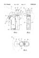
- FIG. 1is a side view of the combination portable fan and spray misting device according to a first preferred embodiment of the present invention
- FIG. 2is a rear view of the combination portable fan and misting device illustrated in FIG. 1 and illustrating a diametrical overlap of the paths of the atomized spray mist and angularly oriented and rotating fan blade head portion;
- FIG. 3is a bottom view of the combination portable fan and misting device according to the embodiment illustrated in FIGS. 1 and 2;
- FIG. 4is a side exploded view of the portable fan according to the first preferred embodiment
- FIG. 5is a rear exploded view of the portable fan as illustrated in FIG. 4;
- FIG. 6is a side exploded view similar to that shown in FIG. 4 and further illustrating the spray misting device and the releasably engaging means for securing the misting device to the portable fan;
- FIG. 7is a bottom exploded view of the portable fan and spray misting device illustrated in FIG. 6;
- FIG. 8is a rear view of the combination portable fan and dual fluid enclosure spray misting device according to a further preferred embodiment of the present invention.
- FIG. 8ais a modification of the combination portable fan and dual fluid enclosure device according to the present invention.
- FIG. 9is a side exploded view similar to that illustrated in FIG. 6 and showing the combination portable fan and spray misting device according to the embodiment of FIG. 8;
- FIG. 10is a bottom exploded view of the fan and spray misting device of FIG. 8 and 9;
- FIG. 11is a top view of an alternative variant of the double spray misting bottle design
- FIG. 12is a side view of the combination portable fan and spray misting device according to a still further preferred embodiment of the present invention.
- FIG. 13is a top view of the further preferred embodiment according to FIG. 12 illustrated without the sprayer head or fan blade unit;
- FIG. 14is a frontal view the spray misting device according to the further preferred embodiment of FIG. 12;
- FIG. 15is a side view of a body of the portable fan enclosure according to the further preferred embodiment of FIG. 12;
- FIG. 16is a view similar to that illustrated in FIG. 15 and further showing in phantom an internal view of the portable fan body;
- FIG. 17is a top view of the portable fan enclosure illustrated in FIGS. 15 and 16;
- FIG. 18is a view of the intermediate flexible neck portion which is attachable to the portable fan body as illustrated in FIG. 12 according to the further preferred embodiment of the present invention.
- FIG. 19is a view similar to that shown in FIG. 18 and further illustrating in phantom first and second attachment ends of the intermediate flexible neck portion according to the further preferred embodiment of the present invention.
- FIG. 20is a view of a fan motor hub forming a part of the fan blade head portion according to the further preferred embodiment of the present invention.
- FIG. 21is a frontal view of a fan blade head unit which is rotatably engaged with the head portion according to the further preferred embodiment of the present invention.
- a combination fan and spray misting device 10is shown according to a first preferred embodiment of the present invention and includes a fan portion 12 and a misting device portion 14.
- Both the fan portion 12 and misting device portion 14are preferably constructed of a durable plastic or the like and, as is also illustrated in FIGS. 4, 5 and 7, the fan portion 12 includes an elongated body portion 16 and an integrally formed and upwardly angularly extending head portion 18 to which is attached a rotating fan blade unit 20 incorporating a plurality of individual fan blades 22.
- the body of the fan blade unit 20includes a longitudinally extending apertured portion, indicated as a bore 24 in the impeller hub, which receives a rotating shaft portion 26 extending from the upwardly angularly extending head portion 18.
- the individual fan blades 22are further preferably constructed of a smooth edged and flexible rubber or plastic material and, as is best illustrated in FIGS. 2 and 3, define a first diametrical blade path 28.
- the fan's elongated body portion 16is illustrated in exploded view in FIGS. 5 and 7 and includes a first elongated half portion 16' and a second elongated half portion 16".
- the half portions 16' and 16"are assembleable together in alignment by a plurality of ribbed portions 29 (FIG. 5) extending from the half portion 16' which align with respective apertured portions in the half 16".
- the half portion 16"includes gripping tabs 30 which facilitate assembly and disassembly of the portions 16' and 16" and, as is best shown in FIGS. 4 and 5, fasteners 31 are insertable within apertures 32 formed in the half portion 16' and engage the half portion 16" to secure the halves together.
- the halves 16' and 16"define a cavity therebetween sufficient for holding a single or double conventional "AA" sized alkaline batteries 33.
- the fan 12also includes a portable electric motor 34 which is situated within the upwardly angled head portion 18 and in electrical communication with the batteries 33.
- a base of the rotating shaft portion 26is mounted within the electric motor 34 and rotatably drives the shaft 26 which extends from the angled head portion 18.
- a cap portion 36is securable to an open bottom of the fan body 16 and closes the body 16 once the batteries are inserted.
- the cap portion 36preferably includes an internally configured spring contact portion 37 and is rotated so that the contact portion 37 is aligned in position with a pair of terminals to engage the internally carried battery in continuous electrical contact with the portable electric motor 34.
- An on/off button for activating and deactivating the portable fanmay preferably be incorporated into the bottom engaging cap portion 36 and is engaged by rotating the cap portion from a first off position to a second on position as is evident by the arrow 38 in FIG. 1.
- An alternatively shaped on/off button (not shown) or the likecan be emplaced anywhere upon the fan body which is easily reachable by a user and is in electrical communication with the battery and electric motor attachment as is desired.
- an aperture 39may be formed within an upper corner of the fan body 16 and is particularly useful for receiving a rope, chain or the like (not shown) for permitting the fan device 12 to be suspended around a wearers neck, with or without attachment of the misting device 14 as will be subsequently described.
- the misting device portion 14includes an elongated and internally hollowed body 40 and an open neck portion 42 at an upper end thereof.
- the neck portion 42is externally threaded at 44 and receives a screw cap 46 with interengaging and internally placed threads (not shown) so as to secure the cap 46 atop the misting device 14.
- a fluid withdrawing tube portion 47 or the likeextends downwardly from the screw cap 46 into the open interior of the body 40 and acts to withdraw a desired fluid held within the body, such as water, suntan lotion and the like, upon the downward depression of a push button portion 48 mounted atop the screw cap 46.
- a passageway 49is formed in the portion 48 in communication with the withdrawing tube portion 47 and, upon downward depression of the button portion 48, distributes an atomized mist spray along a second diametrical path 50 which, as illustrated in FIG. 2, overlaps with the first diametrical blade path 28 of the fan blades 22.
- a non-use and storage cap portion 52is releasably securable over the push button portion 48 and the body portion 40 of the misting device 14 further includes a pair of substantially bulbous end shaped and forwardly projecting portions 54 which are vertically spaced apart along an associated forward vertical face of the misting device body 40 and which engage within associating negative apertured portions formed in a rear face of the fan body 16.
- the bulbous end shaped portions 54are illustrated in operative engagement in FIGS. 1-3 and it is evident that the contours of the apertures as subsequently described are such that the bulbous shaped portions are twisted and snapped into place to mount the misting device to the rear of the fan body.
- the primary means for attaching the misting device 14 to the fan portion 12is provided by a pair of rotatably configured and slotted members 56 formed on a substantially flattened and rear face of the fan body 12.
- Each of the slotted members 56includes a first width portion 58 through which is inserted the bulbous portions 54, a second narrowed width portion 59 and a third further narrowed portion 60 so that, upon alignment of the bulbous end shaped portions extending from the misting device 14, the fan device 12 is rotated to engage the interconnecting neck portions of the bulbous end portions 54 within the progressively constructed and narrowed width portions and to thereby releasably engage the misting device to the fan body.
- FIGS. 8-11a combination portable fan and misting spray device 62 is illustrated according to a yet further preferred embodiment of the present invention and incorporates all of the operative features of the fan body 12 substantially as described with reference to FIGS. 1-7.
- the embodiment 62 of FIGS. 8-11differs from the initially disclosed embodiment in that the single fluid carrying misting device container is replaced by a pair of first 64 and second 66 fluid carrying containers which extend in a generally elongated and parallel manner and which are interconnected by an elongated webbed connection 68.
- the first fluid carrying container 64terminates in a neck portion 69 and the second fluid carrying container 66 in a likewise neck portion 70 similarly as disclosed in the misting device 14 according to FIGS. 1-7.
- Interengaging threads 72are provided on the open neck portion 69 and similar threads 74 on the neck portion 70 to facilitate the screw attachment of screw caps.
- a first screw cap 76 upon which is mounted a first push button portion 78is attached to the first fluid carrying container 64 and a second screw cap 80 upon which is mounted a second push button portion 82 is attached to the second fluid carrying container 66.
- the push button portions 78 and 82are operable either separably or in tandem to create first and second diametrical spray patterns 84 and 86, respectively, in relationship to the diametrical blade path 28 of the fan blade portion 20 as previously described.
- the fluid carrying containersare otherwise actuable similarly as described in the first preferred embodiment and the atomized mist spray, upon contacting the turbulent air currents generated by the fan blade unit 20, create a cooled and further atomized mist spray for any desired application.
- Non-use and storage cap portions 88 and 90are provided and attach over the push button portions 78 and 82 similarly as previously described.
- a modification 62'is shown of the combination portable fan and spray misting device and differs from the embodiment 62 in that a first 64' of the fluid carrying containers is similar to the container 64 previously described having a spray pump 78' and a second 66' of the containers is provided which is taller and includes a lotion applicator 82'.
- the applicator 82'includes a contoured head portion 84' with an applicating nozzle 86' and a downwardly depressible tube 88' secured within a rotatable locking collar 96'.
- the modification 62' of the further preferred embodimentis intended to permit the user to apply a water or similar cooling fluid in an atomized manner within the fluid carrying container 64' while further permitting a suntan lotion, moisturizing cream or similar conventional viscous substance to be contained within the container 66'.
- the applicator 82'is further capable of being rotated in the direction indicated by the arrow to enable the user to apply the lotion to the side of the fan blade unit 20.
- an intermediate clip portion 92may be provided according to one further preferred variant for releasably securing the dual spray bottle attachments 64 and 66 to the portable fan device 12.
- the clip portion 92includes an elongated body portion 94 as is illustrated in side and cross sectional view in FIGS. 9 and 10, respectively, and further includes a plurality of bulbous end shaped and forwardly extending portions 96 as well as first and second pairs of laterally deflectable engaging portions 98 extending rearwardly from the body portion 94.
- a pair of internally configured apertures 100are formed in a rear face of the fan body 12 as shown in FIG.
- aperturesmay be formed in the webbed connection 68 in a like spaced apart manner to permit the pairs of laterally deflectable engaging portions to engage the misting bottle arrangement.
- FIG. 8a first pair of bulbous end shaped projecting portions is illustrated at 104 projecting from the first fluid carrying container 64 and a second pair of like shaped portions is illustrated at 106 projecting from the second fluid carrying container 66 each in similar fashion as described in the first preferred embodiment according to FIGS. 1-7.
- the portable fan 12is illustrated substantially in phantom so that additional pairs of rotatably configured slot members 108 and 110 which correspond in arrangement with the bulbous end shaped portions 104 and 106 are illustrated and which permit the spray misting device to be rotatably and releasably engaged with the fan body in similar fashion as previously described.
- FIGS. 8-11provides a useful two bottle construction to permit both the application of a greater volume of atomized spray as well as the ability to apply the spray at different degrees of inclination relative to the path of the rotating fan blades 22.
- a combination fan and spray misting device 112is illustrated according to the further preferred embodiment of the present invention and includes a portable fan body portion 114 and a misting device portion 116.
- the misting device 116according to this further preferred embodiment is for the most part a well known spray device for applying such items as window cleaner, wood polishing liquid and the like and it is envisioned that any such commonly available spray misting device as is known in the art can be incorporated for use with the fan 114 as will be subsequently described.
- the misting device portion 116includes a body 118 which is internally hollowed and terminates in an upwardly extending and narrowed portion 120 which in turn terminates in an externally threaded neck portion 122.
- a rotatable screw cap 124is attachable over the neck portion 122 of the body 118 and further includes a spray head portion 126 which is disposed above the body 118 of the misting device 116.
- a depressible trigger portion 128is operatively connected to the spray head portion 126 and, upon being actuated, issues from a nozzle portion 130 a spray mist pattern 132 according to the desired fluid contents of the container body 116.
- the portable fan body portion 114includes an elongated body and battery carrying compartment 134, a generally upwardly extending and flexible/repositionable elongated neck portion 136, a fan head portion 138 and a rotating blade portion 140 upon which is arrayed a plurality of individual fan blades 142 (see also FIG. 21).
- the function of the specific components of the fan body portion 114will now be explained with reference to the furthering FIGS. 15-21 as will now be described.
- the elongated body and battery carrying compartment 134includes an elongated cylindrical and generally hollow portion which terminates in an upwardly extending and reduced diameter neck portion 144, the neck portion 144 including a plurality of externally arrayed threads for engaging the elongated and repositionable flexible neck portion 136 as will be subsequently described.
- a pair of batteries 146ideally AA alkaline batteries, are held within the hollow interior cavity formed within the fan body 134 and are maintained in a centralized area of the body interior by a plurality of inwardly extending locator ribs 148 which are arranged at spaced apart locations along the height of the body interior.
- the batteries 146are easily inserted axially through the neck portion 144 and are situated so as to be in electrical communication with the flexible neck portion 136 and are situated at a predetermined axial height by virtue of a spring electrical contact 150 positioned in a base of the body interior cavity.
- the contact 150serves the dual purpose of completing an electrical circuit and exerting force against the batteries so that raised parts 151 hold their position and maintain good contact.
- the body 134 of the portable fan deviceincludes a flattened face 152 and a rounded face 154 for facilitating attachment to the spray bottle body 118.
- the elongated flexible and repositionable neck portion 136includes an elongated member 156 which terminates in a first end in fan body attaching portion 158 and includes a rotatable collar portion 160 with internally positioned threads (not shown) which secures over the threads of the neck portion 144 of the fan body 134 to secure the elongated neck portion 144 to the body 134 of the fan.
- the elongated member 156is preferably constructed of either a rubberized or plastic material and incorporates an internal deformable structure as is known in the art to facilitate fixed repositioning of the member 136 and further includes electrical communicating means which are operable to draw power from the batteries located in the body 134 and transmit it to the fan head portion 138.
- the elongated member 156terminates in a second end in a fan head attaching portion 162 and includes a further rotating collar 164.
- the fan head portion 138includes a reduced diameter neck portion 166 with externally placed threads which receives the rotating collar 164 to securely position the fan head 138 to the end of the elongated flexible neck portion 136.
- a further coil spring 168is positioned within an open interior of the attaching portion 162 and facilitates the electrical contact with the fan head portion 138.
- a portable electric motor 169is incorporated into the fan head portion 138 as is illustrated in phantom and further includes a rotatably driven shaft portion 171 which supports the blade driving portion 140 as shown.
- an on/off switch 170is incorporated into the rotating collar assembly 164 and, upon a slight degree of rotative movement, selectively activates and deactivates the fan head portion 138.
- a pair of bulbous end shaped portions 172project forwardly from the body 118 of the spray bottle 116 and are received in like configured apertures 174 in associated spaced apart locations in a rear face of the fan elongated body 134.
- the portable fan assembly 114is therefore attachable to the spray bottle 116 in a manner so as to permit the fan head portion to be repositionable relative to the spray applicating head of the bottle and to optimize the application of the atomized mist 132.
- the fan assembly 114is also capable of being used separately from the spray bottle 116 such as being placed in an upstanding position.
- the present inventiontherefore discloses a novel combination portable fan and spray misting device which facilitates application of a cooled atomized mist spray for many applications. Additional embodiments will become apparent to those skilled in the art to which it pertains without deviating from the scope of the appended claims.
Landscapes
- Chemical & Material Sciences (AREA)
- Chemical Kinetics & Catalysis (AREA)
- Structures Of Non-Positive Displacement Pumps (AREA)
- Containers And Packaging Bodies Having A Special Means To Remove Contents (AREA)
Abstract
Description
Claims (15)
Priority Applications (1)
| Application Number | Priority Date | Filing Date | Title |
|---|---|---|---|
| US08/808,402US5843344A (en) | 1995-08-17 | 1997-02-28 | Portable fan and combination fan and spray misting device |
Applications Claiming Priority (2)
| Application Number | Priority Date | Filing Date | Title |
|---|---|---|---|
| US08/516,388US5620633A (en) | 1995-08-17 | 1995-08-17 | Spray misting device for use with a portable-sized fan |
| US08/808,402US5843344A (en) | 1995-08-17 | 1997-02-28 | Portable fan and combination fan and spray misting device |
Related Parent Applications (1)
| Application Number | Title | Priority Date | Filing Date |
|---|---|---|---|
| US08/516,388Continuation-In-PartUS5620633A (en) | 1995-08-17 | 1995-08-17 | Spray misting device for use with a portable-sized fan |
Publications (1)
| Publication Number | Publication Date |
|---|---|
| US5843344Atrue US5843344A (en) | 1998-12-01 |
Family
ID=24055359
Family Applications (2)
| Application Number | Title | Priority Date | Filing Date |
|---|---|---|---|
| US08/516,388Expired - LifetimeUS5620633A (en) | 1995-08-17 | 1995-08-17 | Spray misting device for use with a portable-sized fan |
| US08/808,402Expired - LifetimeUS5843344A (en) | 1995-08-17 | 1997-02-28 | Portable fan and combination fan and spray misting device |
Family Applications Before (1)
| Application Number | Title | Priority Date | Filing Date |
|---|---|---|---|
| US08/516,388Expired - LifetimeUS5620633A (en) | 1995-08-17 | 1995-08-17 | Spray misting device for use with a portable-sized fan |
Country Status (2)
| Country | Link |
|---|---|
| US (2) | US5620633A (en) |
| WO (1) | WO1997006882A1 (en) |
Cited By (107)
| Publication number | Priority date | Publication date | Assignee | Title |
|---|---|---|---|---|
| US5965067A (en)* | 1995-09-01 | 1999-10-12 | Circulair, Inc. | Portable fan device for use with a spray misting bottle |
| US6161777A (en)* | 1997-08-08 | 2000-12-19 | C. Michael Carter | Portable spraying and drinking apparatus |
| US6216961B1 (en)* | 1999-05-12 | 2001-04-17 | Misty Mate Inc | Fan propelled mister |
| US6237896B1 (en)* | 1999-10-22 | 2001-05-29 | Ricky D. Hicks | Portable fan with misting nozzles |
| US6378845B1 (en)* | 2000-10-02 | 2002-04-30 | Chin-Tien Hsu | Portable combination fan and humidifier |
| US6440190B1 (en) | 2000-08-16 | 2002-08-27 | Michael E. Goyetche | Portable exhaust fan for removing airborne hazardous materials |
| US20040089745A1 (en)* | 2002-11-07 | 2004-05-13 | Zimmerman Robert P. | Side handle mist sprayer |
| US20050106018A1 (en)* | 2003-11-17 | 2005-05-19 | Ed Stengel | Necklace fan |
| US20050150976A1 (en)* | 2004-01-12 | 2005-07-14 | Ed Stengel | Portable spray fan |
| US20050279854A1 (en)* | 2004-06-17 | 2005-12-22 | S.C. Johnson & Son, Inc. | Liquid atomizing device with reduced settling of atomized liquid droplets |
| US20060273195A1 (en)* | 2005-06-03 | 2006-12-07 | Eric Junkel | Portable misting fan with closely integrated pump |
| US20070077140A1 (en)* | 2005-10-03 | 2007-04-05 | Shimon Silberfenig | Packaging for dispensing a fluid |
| USD544078S1 (en) | 2005-06-03 | 2007-06-05 | Brookstone Purchasing, Inc. | Fan with misting capability |
| USD554242S1 (en) | 2006-08-10 | 2007-10-30 | Glj, Llc | Misting fan |
| US20080047291A1 (en)* | 2006-08-25 | 2008-02-28 | Wind Merchants Ip, Llc. | Personal or spot area environmental management systems and apparatuses |
| US20080069694A1 (en)* | 2006-09-19 | 2008-03-20 | Hector Ray Hernandez | Electric fan |
| US20080169575A1 (en)* | 2007-01-16 | 2008-07-17 | Yung Chen | Portable misting device |
| US20080237899A1 (en)* | 2007-03-28 | 2008-10-02 | Yung Chen | Break resistant joint |
| US20090108475A1 (en)* | 2007-10-31 | 2009-04-30 | Richard Goldmann | Device for applying cooling mist and dry air to individuals |
| US20090121047A1 (en)* | 2007-11-14 | 2009-05-14 | Stylus, Inc. | Fan spray device |
| US7566048B1 (en) | 2008-09-18 | 2009-07-28 | Stylus, Inc. | Fan spray device |
| US20100123023A1 (en)* | 2008-11-20 | 2010-05-20 | Disney Enterprises, Inc. | Personal misting device with manually-operated and retractable folding fan |
| US20100225012A1 (en)* | 2009-03-04 | 2010-09-09 | Dyson Technology Limited | Humidifying apparatus |
| USD629066S1 (en)* | 2010-04-28 | 2010-12-14 | Way2Cool, Inc. | Personal misting device |
| US8123290B1 (en) | 2009-06-17 | 2012-02-28 | BreezzAngel, LLC | Portable cooling device |
| US8246317B2 (en) | 2009-03-04 | 2012-08-21 | Dyson Technology Limited | Fan assembly |
| US20120261843A1 (en)* | 2011-04-18 | 2012-10-18 | Gregory Steiner | Manual misting fan |
| US20120261842A1 (en)* | 2011-04-18 | 2012-10-18 | Greg Steiner | Manual misting fan |
| US8308432B2 (en) | 2009-03-04 | 2012-11-13 | Dyson Technology Limited | Fan assembly |
| US8348596B2 (en) | 2009-03-04 | 2013-01-08 | Dyson Technology Limited | Fan assembly |
| US8348629B2 (en) | 2008-09-23 | 2013-01-08 | Dyston Technology Limited | Fan |
| US8366403B2 (en) | 2010-08-06 | 2013-02-05 | Dyson Technology Limited | Fan assembly |
| US8403640B2 (en) | 2009-03-04 | 2013-03-26 | Dyson Technology Limited | Fan assembly |
| US8403650B2 (en) | 2007-09-04 | 2013-03-26 | Dyson Technology Limited | Fan |
| US8408869B2 (en) | 2009-03-04 | 2013-04-02 | Dyson Technology Limited | Fan assembly |
| US8430624B2 (en) | 2009-03-04 | 2013-04-30 | Dyson Technology Limited | Fan assembly |
| US8454322B2 (en) | 2009-11-06 | 2013-06-04 | Dyson Technology Limited | Fan having a magnetically attached remote control |
| US8469660B2 (en) | 2009-03-04 | 2013-06-25 | Dyson Technology Limited | Fan assembly |
| US8469658B2 (en) | 2009-03-04 | 2013-06-25 | Dyson Technology Limited | Fan |
| WO2013132220A1 (en)* | 2012-03-06 | 2013-09-12 | Dyson Technology Limited | Humidifying apparatus |
| US8613601B2 (en) | 2009-03-04 | 2013-12-24 | Dyson Technology Limited | Fan assembly |
| US8714937B2 (en) | 2009-03-04 | 2014-05-06 | Dyson Technology Limited | Fan assembly |
| US8721286B2 (en) | 2009-03-04 | 2014-05-13 | Dyson Technology Limited | Fan assembly |
| US8734094B2 (en) | 2010-08-06 | 2014-05-27 | Dyson Technology Limited | Fan assembly |
| US8770946B2 (en) | 2010-03-23 | 2014-07-08 | Dyson Technology Limited | Accessory for a fan |
| US8873940B2 (en) | 2010-08-06 | 2014-10-28 | Dyson Technology Limited | Fan assembly |
| US8882451B2 (en) | 2010-03-23 | 2014-11-11 | Dyson Technology Limited | Fan |
| US8894354B2 (en) | 2010-09-07 | 2014-11-25 | Dyson Technology Limited | Fan |
| WO2015024182A1 (en)* | 2013-08-19 | 2015-02-26 | Fan Shuyin | Fan |
| WO2015024186A1 (en)* | 2013-08-19 | 2015-02-26 | Fan Shuyin | Fan |
| US8967980B2 (en) | 2010-10-18 | 2015-03-03 | Dyson Technology Limited | Fan assembly |
| US8967979B2 (en) | 2010-10-18 | 2015-03-03 | Dyson Technology Limited | Fan assembly |
| US9011116B2 (en) | 2010-05-27 | 2015-04-21 | Dyson Technology Limited | Device for blowing air by means of a nozzle assembly |
| USD728092S1 (en) | 2013-08-01 | 2015-04-28 | Dyson Technology Limited | Fan |
| USD728770S1 (en) | 2013-08-01 | 2015-05-05 | Dyson Technology Limited | Fan |
| USD728769S1 (en) | 2013-08-01 | 2015-05-05 | Dyson Technology Limited | Fan |
| USD729372S1 (en) | 2013-03-07 | 2015-05-12 | Dyson Technology Limited | Fan |
| USD729374S1 (en) | 2013-03-07 | 2015-05-12 | Dyson Technology Limited | Fan |
| USD729375S1 (en) | 2013-03-07 | 2015-05-12 | Dyson Technology Limited | Fan |
| USD729373S1 (en) | 2013-03-07 | 2015-05-12 | Dyson Technology Limited | Fan |
| USD729376S1 (en) | 2013-03-07 | 2015-05-12 | Dyson Technology Limited | Fan |
| USD729925S1 (en) | 2013-03-07 | 2015-05-19 | Dyson Technology Limited | Fan |
| US9127689B2 (en) | 2009-03-04 | 2015-09-08 | Dyson Technology Limited | Fan assembly |
| US9127855B2 (en) | 2011-07-27 | 2015-09-08 | Dyson Technology Limited | Fan assembly |
| US9151299B2 (en) | 2012-02-06 | 2015-10-06 | Dyson Technology Limited | Fan |
| US20150285598A1 (en)* | 2014-04-02 | 2015-10-08 | Michael Flynn | Dual Purpose Self-Defense Device |
| USD746425S1 (en) | 2013-01-18 | 2015-12-29 | Dyson Technology Limited | Humidifier |
| USD746966S1 (en) | 2013-01-18 | 2016-01-05 | Dyson Technology Limited | Humidifier |
| USD747450S1 (en) | 2013-01-18 | 2016-01-12 | Dyson Technology Limited | Humidifier |
| US9249809B2 (en) | 2012-02-06 | 2016-02-02 | Dyson Technology Limited | Fan |
| USD749231S1 (en) | 2013-01-18 | 2016-02-09 | Dyson Technology Limited | Humidifier |
| US9283573B2 (en) | 2012-02-06 | 2016-03-15 | Dyson Technology Limited | Fan assembly |
| US9328739B2 (en) | 2012-01-19 | 2016-05-03 | Dyson Technology Limited | Fan |
| US9410711B2 (en) | 2013-09-26 | 2016-08-09 | Dyson Technology Limited | Fan assembly |
| USD767747S1 (en)* | 2015-03-23 | 2016-09-27 | Connie Wang | Handheld fan |
| US9458853B2 (en) | 2011-07-27 | 2016-10-04 | Dyson Technology Limited | Fan assembly |
| USD770022S1 (en)* | 2015-03-06 | 2016-10-25 | O2Cool, Llc | Water misting fan |
| US9513028B2 (en) | 2009-03-04 | 2016-12-06 | Dyson Technology Limited | Fan assembly |
| US9568006B2 (en) | 2012-05-16 | 2017-02-14 | Dyson Technology Limited | Fan |
| US9568021B2 (en) | 2012-05-16 | 2017-02-14 | Dyson Technology Limited | Fan |
| US9599356B2 (en) | 2014-07-29 | 2017-03-21 | Dyson Technology Limited | Humidifying apparatus |
| US20170198703A1 (en)* | 2016-01-13 | 2017-07-13 | Jeff Leitman | Fan Powered by Mobile Device |
| US9732763B2 (en) | 2012-07-11 | 2017-08-15 | Dyson Technology Limited | Fan assembly |
| US9745996B2 (en) | 2010-12-02 | 2017-08-29 | Dyson Technology Limited | Fan |
| US9745981B2 (en) | 2011-11-11 | 2017-08-29 | Dyson Technology Limited | Fan assembly |
| US9752789B2 (en) | 2012-03-06 | 2017-09-05 | Dyson Technology Limited | Humidifying apparatus |
| US9797613B2 (en) | 2012-03-06 | 2017-10-24 | Dyson Technology Limited | Humidifying apparatus |
| US9797612B2 (en) | 2013-01-29 | 2017-10-24 | Dyson Technology Limited | Fan assembly |
| US9797414B2 (en) | 2013-07-09 | 2017-10-24 | Dyson Technology Limited | Fan assembly |
| US9816531B2 (en) | 2008-10-25 | 2017-11-14 | Dyson Technology Limited | Fan utilizing coanda surface |
| US9822778B2 (en) | 2012-04-19 | 2017-11-21 | Dyson Technology Limited | Fan assembly |
| US9903602B2 (en) | 2014-07-29 | 2018-02-27 | Dyson Technology Limited | Humidifying apparatus |
| US9927136B2 (en) | 2012-03-06 | 2018-03-27 | Dyson Technology Limited | Fan assembly |
| US9926804B2 (en) | 2010-11-02 | 2018-03-27 | Dyson Technology Limited | Fan assembly |
| US9982677B2 (en) | 2014-07-29 | 2018-05-29 | Dyson Technology Limited | Fan assembly |
| US10094392B2 (en) | 2011-11-24 | 2018-10-09 | Dyson Technology Limited | Fan assembly |
| US10100836B2 (en) | 2010-10-13 | 2018-10-16 | Dyson Technology Limited | Fan assembly |
| US10145583B2 (en) | 2012-04-04 | 2018-12-04 | Dyson Technology Limited | Heating apparatus |
| US10226037B2 (en) | 2015-03-25 | 2019-03-12 | Clarke Consumer Products, Inc. | Fluid dispensing device |
| US10408478B2 (en) | 2012-03-06 | 2019-09-10 | Dyson Technology Limited | Humidifying apparatus |
| US10428837B2 (en) | 2012-05-16 | 2019-10-01 | Dyson Technology Limited | Fan |
| US10465928B2 (en) | 2012-03-06 | 2019-11-05 | Dyson Technology Limited | Humidifying apparatus |
| US10612565B2 (en) | 2013-01-29 | 2020-04-07 | Dyson Technology Limited | Fan assembly |
| US11466894B1 (en) | 2021-08-06 | 2022-10-11 | Tyler Perrelle | Compact orientation-adjustable mister-fan apparatus |
| US11629869B1 (en) | 2022-03-16 | 2023-04-18 | Ontel Products Corporation | Personal air cooler |
| USD1018821S1 (en) | 2022-03-16 | 2024-03-19 | Ontel Products Corporation | Portable air cooler |
| USD1018822S1 (en) | 2022-03-16 | 2024-03-19 | Ontel Products Corporation | Portable air cooler |
Families Citing this family (21)
| Publication number | Priority date | Publication date | Assignee | Title |
|---|---|---|---|---|
| US5620633A (en)* | 1995-08-17 | 1997-04-15 | Circulair, Inc. | Spray misting device for use with a portable-sized fan |
| US5740948A (en)* | 1997-02-03 | 1998-04-21 | Chu; Wei-Yieh | Multi-functional compound integrated bottle |
| DE19729260A1 (en)* | 1997-07-09 | 1999-01-14 | Gerhard Zehdnicker | Fog-making device |
| US6217294B1 (en)* | 1999-02-16 | 2001-04-17 | Terry E. Arnieri | Combination container with mounted fan |
| US20020148909A1 (en)* | 1999-04-12 | 2002-10-17 | Junkel Eric F. | Cooling device using fan-driven misting with large bottom fill port |
| US6398132B1 (en) | 1999-04-12 | 2002-06-04 | Circulair, Inc. | Cooling device using fan-driven misting with large fill and drinking port |
| US6325362B1 (en) | 1999-05-26 | 2001-12-04 | Raymond O. Massey | Cooling and misting apparatus for evaporative cooling of open-air vehicle occupants |
| US7524511B1 (en)* | 2000-07-12 | 2009-04-28 | Rogue Valley Natural Springs, Inc. | Method and kit for moisturizing the surface of the eye |
| US6588372B1 (en)* | 2001-09-28 | 2003-07-08 | Michael E. Terrell | Gear drive livestock fan |
| US7082775B1 (en) | 2003-11-03 | 2006-08-01 | Emergency Water Solutions, Inc. | Heat exhaustion evaporative cooling |
| US8596556B2 (en)* | 2005-02-22 | 2013-12-03 | Vehicle Enhancement Labs | Radiator and air cooler mister |
| US7150162B1 (en)* | 2005-09-06 | 2006-12-19 | Brunner Tracy D | Stroller with misting system |
| USD546194S1 (en) | 2006-02-06 | 2007-07-10 | Shimon Silberfenig | Packaging for dispensing a fluid |
| US7806388B2 (en)* | 2007-03-28 | 2010-10-05 | Eric Junkel | Handheld water misting fan with improved air flow |
| US20080244954A1 (en)* | 2007-04-03 | 2008-10-09 | Samuel Shannon | Hunter's Scent Dispersing Apparatus |
| CN201425031Y (en) | 2009-04-16 | 2010-03-17 | 麦志坚 | Blowing fan with water mist function |
| US8893984B2 (en)* | 2012-07-16 | 2014-11-25 | Michael Sands | Misting bottle with fan |
| US9267698B2 (en) | 2014-02-28 | 2016-02-23 | Techtronic Power Tools Technology Limited | Mister fan |
| US10330333B2 (en)* | 2014-04-29 | 2019-06-25 | Bryan Kaleta | Portable misting fan with pivoting head |
| CN106152355A (en)* | 2015-07-29 | 2016-11-23 | 洛阳新巨能高热技术有限公司 | A kind of Novel atomizing device |
| US11358167B2 (en)* | 2020-01-22 | 2022-06-14 | Elc Management Llc | Reusable pump dispenser |
Citations (15)
| Publication number | Priority date | Publication date | Assignee | Title |
|---|---|---|---|---|
| US1993635A (en)* | 1933-08-08 | 1935-03-05 | Towt Charles Warren | Apparatus for preventing damage to vegetation by frosting and sunburning temperatures |
| US2736606A (en)* | 1953-09-11 | 1956-02-28 | Thomas E Kmiotek | Spray gun attachment for portable electric drills |
| US3997115A (en)* | 1976-03-10 | 1976-12-14 | Lawrence Peska Associates, Inc. | Portable atomizer for liquids |
| USD264181S (en) | 1980-05-02 | 1982-05-04 | Booso Carol A | Combined bottle and brush |
| US4523080A (en)* | 1983-03-14 | 1985-06-11 | Bolton John D | Apparatus for treatment of hair and scalp |
| US4700494A (en)* | 1986-09-15 | 1987-10-20 | Pridgen Danny W | Apparatus for drying hair spray and other compositions |
| USD292556S (en) | 1984-08-06 | 1987-11-03 | Tannies Corporation | Bottle |
| US4839106A (en)* | 1988-05-12 | 1989-06-13 | Gregory A. Steiner | Portable misting fan |
| US5082177A (en)* | 1990-01-31 | 1992-01-21 | Hill Daryl G | Fluid injection spray system |
| USD349570S (en) | 1993-07-20 | 1994-08-09 | Circulair, Inc. | Small electric fan |
| US5338495A (en)* | 1993-10-18 | 1994-08-16 | Innovative Design Enterprises | Portable misting fan |
| US5620633A (en)* | 1995-08-17 | 1997-04-15 | Circulair, Inc. | Spray misting device for use with a portable-sized fan |
| US5667731A (en)* | 1995-09-01 | 1997-09-16 | Circulair, Inc. | Portable fan device for use with a spray misting bottle |
| US5667732A (en)* | 1995-08-30 | 1997-09-16 | Lederer; Jeffrey H. | Compact portable misting fan |
| US5715999A (en)* | 1996-01-30 | 1998-02-10 | Hsu; Chin-Tien | Atomizer |
Family Cites Families (11)
| Publication number | Priority date | Publication date | Assignee | Title |
|---|---|---|---|---|
| US2079117A (en)* | 1936-09-05 | 1937-05-04 | Russell R Hays | Atomizing fan |
| US2351226A (en)* | 1943-09-27 | 1944-06-13 | William P Pernhall | Atomizer |
| US2608792A (en)* | 1949-09-09 | 1952-09-02 | Fmc Corp | Moistened dust spraying machine |
| US2787501A (en)* | 1956-04-23 | 1957-04-02 | Frank J Tuma | Window cleaning device |
| US2937712A (en)* | 1958-09-22 | 1960-05-24 | James H Woods | Air de-contaminator |
| US3296739A (en)* | 1965-02-17 | 1967-01-10 | B L Johnson | Rotating orchard heater |
| US3659791A (en)* | 1969-11-17 | 1972-05-02 | William O Clark | Spray gun adaptor for aerosal cans |
| US3734357A (en)* | 1971-09-10 | 1973-05-22 | N Batistelli | Portable holder for pressurized containers |
| US4235377A (en)* | 1978-11-29 | 1980-11-25 | The Wooster Brush Company | Portable paint spraying device |
| US4399794A (en)* | 1981-10-29 | 1983-08-23 | Gagnon David C | Carburetion system |
| US4911361A (en)* | 1987-02-05 | 1990-03-27 | Atsushi Tada | Manually operated trigger type dispenser, method of assembling the same, and a spinner for use in the dispenser |
- 1995
- 1995-08-17USUS08/516,388patent/US5620633A/ennot_activeExpired - Lifetime
- 1996
- 1996-08-16WOPCT/US1996/013288patent/WO1997006882A1/enactiveApplication Filing
- 1997
- 1997-02-28USUS08/808,402patent/US5843344A/ennot_activeExpired - Lifetime
Patent Citations (15)
| Publication number | Priority date | Publication date | Assignee | Title |
|---|---|---|---|---|
| US1993635A (en)* | 1933-08-08 | 1935-03-05 | Towt Charles Warren | Apparatus for preventing damage to vegetation by frosting and sunburning temperatures |
| US2736606A (en)* | 1953-09-11 | 1956-02-28 | Thomas E Kmiotek | Spray gun attachment for portable electric drills |
| US3997115A (en)* | 1976-03-10 | 1976-12-14 | Lawrence Peska Associates, Inc. | Portable atomizer for liquids |
| USD264181S (en) | 1980-05-02 | 1982-05-04 | Booso Carol A | Combined bottle and brush |
| US4523080A (en)* | 1983-03-14 | 1985-06-11 | Bolton John D | Apparatus for treatment of hair and scalp |
| USD292556S (en) | 1984-08-06 | 1987-11-03 | Tannies Corporation | Bottle |
| US4700494A (en)* | 1986-09-15 | 1987-10-20 | Pridgen Danny W | Apparatus for drying hair spray and other compositions |
| US4839106A (en)* | 1988-05-12 | 1989-06-13 | Gregory A. Steiner | Portable misting fan |
| US5082177A (en)* | 1990-01-31 | 1992-01-21 | Hill Daryl G | Fluid injection spray system |
| USD349570S (en) | 1993-07-20 | 1994-08-09 | Circulair, Inc. | Small electric fan |
| US5338495A (en)* | 1993-10-18 | 1994-08-16 | Innovative Design Enterprises | Portable misting fan |
| US5620633A (en)* | 1995-08-17 | 1997-04-15 | Circulair, Inc. | Spray misting device for use with a portable-sized fan |
| US5667732A (en)* | 1995-08-30 | 1997-09-16 | Lederer; Jeffrey H. | Compact portable misting fan |
| US5667731A (en)* | 1995-09-01 | 1997-09-16 | Circulair, Inc. | Portable fan device for use with a spray misting bottle |
| US5715999A (en)* | 1996-01-30 | 1998-02-10 | Hsu; Chin-Tien | Atomizer |
Cited By (152)
| Publication number | Priority date | Publication date | Assignee | Title |
|---|---|---|---|---|
| US5965067A (en)* | 1995-09-01 | 1999-10-12 | Circulair, Inc. | Portable fan device for use with a spray misting bottle |
| US6161777A (en)* | 1997-08-08 | 2000-12-19 | C. Michael Carter | Portable spraying and drinking apparatus |
| US6216961B1 (en)* | 1999-05-12 | 2001-04-17 | Misty Mate Inc | Fan propelled mister |
| US6237896B1 (en)* | 1999-10-22 | 2001-05-29 | Ricky D. Hicks | Portable fan with misting nozzles |
| US6953491B2 (en) | 2000-08-16 | 2005-10-11 | Michael E. Goyethce | Exhaust fan for removing airborne materials |
| US6440190B1 (en) | 2000-08-16 | 2002-08-27 | Michael E. Goyetche | Portable exhaust fan for removing airborne hazardous materials |
| US6599341B2 (en) | 2000-08-16 | 2003-07-29 | Michael E. Goyetche | Exhaust fan for removing airborne materials |
| US20030205038A1 (en)* | 2000-08-16 | 2003-11-06 | Goyetche Michael E. | Exhaust fan for removing airborne materials |
| US6378845B1 (en)* | 2000-10-02 | 2002-04-30 | Chin-Tien Hsu | Portable combination fan and humidifier |
| US20040089745A1 (en)* | 2002-11-07 | 2004-05-13 | Zimmerman Robert P. | Side handle mist sprayer |
| US6827290B2 (en) | 2002-11-07 | 2004-12-07 | Robert P. Zimmerman | Side handle mist sprayer |
| US20050106018A1 (en)* | 2003-11-17 | 2005-05-19 | Ed Stengel | Necklace fan |
| US6955524B2 (en) | 2003-11-17 | 2005-10-18 | Vectacor (A Division Of Bonis & Co.) | Necklace fan |
| US20050150976A1 (en)* | 2004-01-12 | 2005-07-14 | Ed Stengel | Portable spray fan |
| US7104468B2 (en)* | 2004-01-12 | 2006-09-12 | Vectacor (A Division Of Bonis & Company) | Portable spray fan |
| US20050279854A1 (en)* | 2004-06-17 | 2005-12-22 | S.C. Johnson & Son, Inc. | Liquid atomizing device with reduced settling of atomized liquid droplets |
| US7775459B2 (en) | 2004-06-17 | 2010-08-17 | S.C. Johnson & Son, Inc. | Liquid atomizing device with reduced settling of atomized liquid droplets |
| US20060273195A1 (en)* | 2005-06-03 | 2006-12-07 | Eric Junkel | Portable misting fan with closely integrated pump |
| USD544078S1 (en) | 2005-06-03 | 2007-06-05 | Brookstone Purchasing, Inc. | Fan with misting capability |
| US20070077140A1 (en)* | 2005-10-03 | 2007-04-05 | Shimon Silberfenig | Packaging for dispensing a fluid |
| USD554242S1 (en) | 2006-08-10 | 2007-10-30 | Glj, Llc | Misting fan |
| US20080047291A1 (en)* | 2006-08-25 | 2008-02-28 | Wind Merchants Ip, Llc. | Personal or spot area environmental management systems and apparatuses |
| US8438867B2 (en) | 2006-08-25 | 2013-05-14 | David Colwell | Personal or spot area environmental management systems and apparatuses |
| US20080069694A1 (en)* | 2006-09-19 | 2008-03-20 | Hector Ray Hernandez | Electric fan |
| US20080169575A1 (en)* | 2007-01-16 | 2008-07-17 | Yung Chen | Portable misting device |
| US8016270B2 (en)* | 2007-01-16 | 2011-09-13 | Yung Chen | Portable misting device |
| US20080237899A1 (en)* | 2007-03-28 | 2008-10-02 | Yung Chen | Break resistant joint |
| US7810794B2 (en)* | 2007-03-28 | 2010-10-12 | Yung Chen | Break resistant joint |
| US8764412B2 (en) | 2007-09-04 | 2014-07-01 | Dyson Technology Limited | Fan |
| US9249810B2 (en) | 2007-09-04 | 2016-02-02 | Dyson Technology Limited | Fan |
| US8403650B2 (en) | 2007-09-04 | 2013-03-26 | Dyson Technology Limited | Fan |
| US8162293B2 (en)* | 2007-10-31 | 2012-04-24 | Richard Goldmann | Device for applying cooling mist and dry air to individuals |
| US20090108475A1 (en)* | 2007-10-31 | 2009-04-30 | Richard Goldmann | Device for applying cooling mist and dry air to individuals |
| US20090121047A1 (en)* | 2007-11-14 | 2009-05-14 | Stylus, Inc. | Fan spray device |
| US7566048B1 (en) | 2008-09-18 | 2009-07-28 | Stylus, Inc. | Fan spray device |
| US8348629B2 (en) | 2008-09-23 | 2013-01-08 | Dyston Technology Limited | Fan |
| US9816531B2 (en) | 2008-10-25 | 2017-11-14 | Dyson Technology Limited | Fan utilizing coanda surface |
| US10145388B2 (en) | 2008-10-25 | 2018-12-04 | Dyson Technology Limited | Fan with a filter |
| US20100123023A1 (en)* | 2008-11-20 | 2010-05-20 | Disney Enterprises, Inc. | Personal misting device with manually-operated and retractable folding fan |
| US7878424B2 (en) | 2008-11-20 | 2011-02-01 | Disney Enterprises, Inc. | Personal misting device with manually-operated and retractable folding fan |
| US8348596B2 (en) | 2009-03-04 | 2013-01-08 | Dyson Technology Limited | Fan assembly |
| US10006657B2 (en) | 2009-03-04 | 2018-06-26 | Dyson Technology Limited | Fan assembly |
| US8348597B2 (en) | 2009-03-04 | 2013-01-08 | Dyson Technology Limited | Fan assembly |
| US8308432B2 (en) | 2009-03-04 | 2012-11-13 | Dyson Technology Limited | Fan assembly |
| US8356804B2 (en)* | 2009-03-04 | 2013-01-22 | Dyson Technology Limited | Humidifying apparatus |
| US20100225012A1 (en)* | 2009-03-04 | 2010-09-09 | Dyson Technology Limited | Humidifying apparatus |
| US8403640B2 (en) | 2009-03-04 | 2013-03-26 | Dyson Technology Limited | Fan assembly |
| US9513028B2 (en) | 2009-03-04 | 2016-12-06 | Dyson Technology Limited | Fan assembly |
| US8408869B2 (en) | 2009-03-04 | 2013-04-02 | Dyson Technology Limited | Fan assembly |
| US8430624B2 (en) | 2009-03-04 | 2013-04-30 | Dyson Technology Limited | Fan assembly |
| US9599368B2 (en) | 2009-03-04 | 2017-03-21 | Dyson Technology Limited | Nozzle for bladeless fan assembly with heater |
| US9127689B2 (en) | 2009-03-04 | 2015-09-08 | Dyson Technology Limited | Fan assembly |
| US8469660B2 (en) | 2009-03-04 | 2013-06-25 | Dyson Technology Limited | Fan assembly |
| US8469658B2 (en) | 2009-03-04 | 2013-06-25 | Dyson Technology Limited | Fan |
| US8469655B2 (en) | 2009-03-04 | 2013-06-25 | Dyson Technology Limited | Fan assembly |
| US8529203B2 (en) | 2009-03-04 | 2013-09-10 | Dyson Technology Limited | Fan assembly |
| US10221860B2 (en) | 2009-03-04 | 2019-03-05 | Dyson Technology Limited | Fan assembly |
| US8246317B2 (en) | 2009-03-04 | 2012-08-21 | Dyson Technology Limited | Fan assembly |
| US8613601B2 (en) | 2009-03-04 | 2013-12-24 | Dyson Technology Limited | Fan assembly |
| US8684687B2 (en) | 2009-03-04 | 2014-04-01 | Dyson Technology Limited | Fan assembly |
| US8708650B2 (en) | 2009-03-04 | 2014-04-29 | Dyson Technology Limited | Fan assembly |
| US8714937B2 (en) | 2009-03-04 | 2014-05-06 | Dyson Technology Limited | Fan assembly |
| US8721286B2 (en) | 2009-03-04 | 2014-05-13 | Dyson Technology Limited | Fan assembly |
| US8932028B2 (en) | 2009-03-04 | 2015-01-13 | Dyson Technology Limited | Fan assembly |
| US8784071B2 (en) | 2009-03-04 | 2014-07-22 | Dyson Technology Limited | Fan assembly |
| US8784049B2 (en) | 2009-03-04 | 2014-07-22 | Dyson Technology Limited | Fan |
| US8783663B2 (en) | 2009-03-04 | 2014-07-22 | Dyson Technology Limited | Humidifying apparatus |
| US8123290B1 (en) | 2009-06-17 | 2012-02-28 | BreezzAngel, LLC | Portable cooling device |
| US8297695B1 (en) | 2009-06-17 | 2012-10-30 | BreezzAngel, LLC | Portable cooling device |
| US8454322B2 (en) | 2009-11-06 | 2013-06-04 | Dyson Technology Limited | Fan having a magnetically attached remote control |
| US9004878B2 (en) | 2009-11-06 | 2015-04-14 | Dyson Technology Limited | Fan having a magnetically attached remote control |
| US8882451B2 (en) | 2010-03-23 | 2014-11-11 | Dyson Technology Limited | Fan |
| US8770946B2 (en) | 2010-03-23 | 2014-07-08 | Dyson Technology Limited | Accessory for a fan |
| USD629066S1 (en)* | 2010-04-28 | 2010-12-14 | Way2Cool, Inc. | Personal misting device |
| US9011116B2 (en) | 2010-05-27 | 2015-04-21 | Dyson Technology Limited | Device for blowing air by means of a nozzle assembly |
| US8734094B2 (en) | 2010-08-06 | 2014-05-27 | Dyson Technology Limited | Fan assembly |
| US8873940B2 (en) | 2010-08-06 | 2014-10-28 | Dyson Technology Limited | Fan assembly |
| US10344773B2 (en) | 2010-08-06 | 2019-07-09 | Dyson Technology Limited | Fan assembly |
| US8366403B2 (en) | 2010-08-06 | 2013-02-05 | Dyson Technology Limited | Fan assembly |
| US8894354B2 (en) | 2010-09-07 | 2014-11-25 | Dyson Technology Limited | Fan |
| US9745988B2 (en) | 2010-09-07 | 2017-08-29 | Dyson Technology Limited | Fan |
| US10100836B2 (en) | 2010-10-13 | 2018-10-16 | Dyson Technology Limited | Fan assembly |
| US8967980B2 (en) | 2010-10-18 | 2015-03-03 | Dyson Technology Limited | Fan assembly |
| US8967979B2 (en) | 2010-10-18 | 2015-03-03 | Dyson Technology Limited | Fan assembly |
| US9926804B2 (en) | 2010-11-02 | 2018-03-27 | Dyson Technology Limited | Fan assembly |
| US9745996B2 (en) | 2010-12-02 | 2017-08-29 | Dyson Technology Limited | Fan |
| US20120261843A1 (en)* | 2011-04-18 | 2012-10-18 | Gregory Steiner | Manual misting fan |
| US20120261842A1 (en)* | 2011-04-18 | 2012-10-18 | Greg Steiner | Manual misting fan |
| US8794599B2 (en)* | 2011-04-18 | 2014-08-05 | Greg Steiner | Manual misting fan |
| US9022360B2 (en)* | 2011-04-18 | 2015-05-05 | Gregory Steiner | Manual misting fan |
| US9291361B2 (en) | 2011-07-27 | 2016-03-22 | Dyson Technology Limited | Fan assembly |
| US10094581B2 (en) | 2011-07-27 | 2018-10-09 | Dyson Technology Limited | Fan assembly |
| US9127855B2 (en) | 2011-07-27 | 2015-09-08 | Dyson Technology Limited | Fan assembly |
| US9458853B2 (en) | 2011-07-27 | 2016-10-04 | Dyson Technology Limited | Fan assembly |
| US9335064B2 (en) | 2011-07-27 | 2016-05-10 | Dyson Technology Limited | Fan assembly |
| US9745981B2 (en) | 2011-11-11 | 2017-08-29 | Dyson Technology Limited | Fan assembly |
| US10094392B2 (en) | 2011-11-24 | 2018-10-09 | Dyson Technology Limited | Fan assembly |
| US9328739B2 (en) | 2012-01-19 | 2016-05-03 | Dyson Technology Limited | Fan |
| US9283573B2 (en) | 2012-02-06 | 2016-03-15 | Dyson Technology Limited | Fan assembly |
| US9249809B2 (en) | 2012-02-06 | 2016-02-02 | Dyson Technology Limited | Fan |
| US9151299B2 (en) | 2012-02-06 | 2015-10-06 | Dyson Technology Limited | Fan |
| US9797613B2 (en) | 2012-03-06 | 2017-10-24 | Dyson Technology Limited | Humidifying apparatus |
| US10408478B2 (en) | 2012-03-06 | 2019-09-10 | Dyson Technology Limited | Humidifying apparatus |
| AU2013229286B2 (en)* | 2012-03-06 | 2016-03-03 | Dyson Technology Limited | Humidifying apparatus |
| WO2013132220A1 (en)* | 2012-03-06 | 2013-09-12 | Dyson Technology Limited | Humidifying apparatus |
| US9366449B2 (en) | 2012-03-06 | 2016-06-14 | Dyson Technology Limited | Humidifying apparatus |
| CN103306944A (en)* | 2012-03-06 | 2013-09-18 | 戴森技术有限公司 | Humidifying apparatus |
| CN103306944B (en)* | 2012-03-06 | 2016-09-14 | 戴森技术有限公司 | Damping device |
| US10563875B2 (en) | 2012-03-06 | 2020-02-18 | Dyson Technology Limited | Humidifying apparatus |
| US10465928B2 (en) | 2012-03-06 | 2019-11-05 | Dyson Technology Limited | Humidifying apparatus |
| US9752789B2 (en) | 2012-03-06 | 2017-09-05 | Dyson Technology Limited | Humidifying apparatus |
| US9927136B2 (en) | 2012-03-06 | 2018-03-27 | Dyson Technology Limited | Fan assembly |
| US10145583B2 (en) | 2012-04-04 | 2018-12-04 | Dyson Technology Limited | Heating apparatus |
| US9822778B2 (en) | 2012-04-19 | 2017-11-21 | Dyson Technology Limited | Fan assembly |
| US9568021B2 (en) | 2012-05-16 | 2017-02-14 | Dyson Technology Limited | Fan |
| US9568006B2 (en) | 2012-05-16 | 2017-02-14 | Dyson Technology Limited | Fan |
| US10428837B2 (en) | 2012-05-16 | 2019-10-01 | Dyson Technology Limited | Fan |
| US10309420B2 (en) | 2012-05-16 | 2019-06-04 | Dyson Technology Limited | Fan |
| US9732763B2 (en) | 2012-07-11 | 2017-08-15 | Dyson Technology Limited | Fan assembly |
| USD746425S1 (en) | 2013-01-18 | 2015-12-29 | Dyson Technology Limited | Humidifier |
| USD747450S1 (en) | 2013-01-18 | 2016-01-12 | Dyson Technology Limited | Humidifier |
| USD746966S1 (en) | 2013-01-18 | 2016-01-05 | Dyson Technology Limited | Humidifier |
| USD749231S1 (en) | 2013-01-18 | 2016-02-09 | Dyson Technology Limited | Humidifier |
| US9797612B2 (en) | 2013-01-29 | 2017-10-24 | Dyson Technology Limited | Fan assembly |
| US10612565B2 (en) | 2013-01-29 | 2020-04-07 | Dyson Technology Limited | Fan assembly |
| USD729373S1 (en) | 2013-03-07 | 2015-05-12 | Dyson Technology Limited | Fan |
| USD729376S1 (en) | 2013-03-07 | 2015-05-12 | Dyson Technology Limited | Fan |
| USD729372S1 (en) | 2013-03-07 | 2015-05-12 | Dyson Technology Limited | Fan |
| USD729375S1 (en) | 2013-03-07 | 2015-05-12 | Dyson Technology Limited | Fan |
| USD729925S1 (en) | 2013-03-07 | 2015-05-19 | Dyson Technology Limited | Fan |
| USD729374S1 (en) | 2013-03-07 | 2015-05-12 | Dyson Technology Limited | Fan |
| US9797414B2 (en) | 2013-07-09 | 2017-10-24 | Dyson Technology Limited | Fan assembly |
| USD728769S1 (en) | 2013-08-01 | 2015-05-05 | Dyson Technology Limited | Fan |
| USD728092S1 (en) | 2013-08-01 | 2015-04-28 | Dyson Technology Limited | Fan |
| USD728770S1 (en) | 2013-08-01 | 2015-05-05 | Dyson Technology Limited | Fan |
| WO2015024186A1 (en)* | 2013-08-19 | 2015-02-26 | Fan Shuyin | Fan |
| WO2015024182A1 (en)* | 2013-08-19 | 2015-02-26 | Fan Shuyin | Fan |
| US9410711B2 (en) | 2013-09-26 | 2016-08-09 | Dyson Technology Limited | Fan assembly |
| US20150285598A1 (en)* | 2014-04-02 | 2015-10-08 | Michael Flynn | Dual Purpose Self-Defense Device |
| US9982677B2 (en) | 2014-07-29 | 2018-05-29 | Dyson Technology Limited | Fan assembly |
| US9599356B2 (en) | 2014-07-29 | 2017-03-21 | Dyson Technology Limited | Humidifying apparatus |
| US9903602B2 (en) | 2014-07-29 | 2018-02-27 | Dyson Technology Limited | Humidifying apparatus |
| USD770022S1 (en)* | 2015-03-06 | 2016-10-25 | O2Cool, Llc | Water misting fan |
| USD807993S1 (en) | 2015-03-06 | 2018-01-16 | O2Cool, Llc | Water misting fan |
| USD767747S1 (en)* | 2015-03-23 | 2016-09-27 | Connie Wang | Handheld fan |
| US10226037B2 (en) | 2015-03-25 | 2019-03-12 | Clarke Consumer Products, Inc. | Fluid dispensing device |
| US11311006B2 (en) | 2015-03-25 | 2022-04-26 | Clarke Consumer Products, Inc. | Container for fluid |
| US20170198703A1 (en)* | 2016-01-13 | 2017-07-13 | Jeff Leitman | Fan Powered by Mobile Device |
| US11466894B1 (en) | 2021-08-06 | 2022-10-11 | Tyler Perrelle | Compact orientation-adjustable mister-fan apparatus |
| US11629869B1 (en) | 2022-03-16 | 2023-04-18 | Ontel Products Corporation | Personal air cooler |
| USD1018821S1 (en) | 2022-03-16 | 2024-03-19 | Ontel Products Corporation | Portable air cooler |
| USD1018822S1 (en) | 2022-03-16 | 2024-03-19 | Ontel Products Corporation | Portable air cooler |
Also Published As
| Publication number | Publication date |
|---|---|
| WO1997006882A1 (en) | 1997-02-27 |
| US5620633A (en) | 1997-04-15 |
Similar Documents
| Publication | Publication Date | Title |
|---|---|---|
| US5843344A (en) | Portable fan and combination fan and spray misting device | |
| US5965067A (en) | Portable fan device for use with a spray misting bottle | |
| US5837167A (en) | Compact portable misting fan | |
| US20230107995A1 (en) | Applicator with collapsible wand | |
| JP2004533304A5 (en) | ||
| US20010010340A1 (en) | Fan propelled mister | |
| EP3970861B1 (en) | Sprayer | |
| NZ264246A (en) | Integral portable fan and atomising unit: fan motor in upper chamber; lower chamber has pump, atomising head aligned with fan, and fluid reservoir connector | |
| JP2003507166A (en) | Hand-held electrostatic spray device | |
| CN213435303U (en) | Atomizer device | |
| JP2001516273A (en) | Improvement of liquid dispensing device and improvement on liquid dispensing device | |
| US12016416B2 (en) | Water dispensing hat | |
| JP2001046920A (en) | Spraying device | |
| US20050212879A1 (en) | Replaceable electrostatically sprayable material reservoir for use with a electrostatic spraying device | |
| JPH04267964A (en) | Ultrasonic atomizer and atomizing and making-up method | |
| CN206682013U (en) | Moisturizing fan | |
| US5957386A (en) | Multi-path spray gun | |
| US20090121047A1 (en) | Fan spray device | |
| JP7546480B2 (en) | Spout head of backpack-type power sprayer | |
| CN214917184U (en) | Spray head structure for electrostatic sprayer | |
| JP7542434B2 (en) | Spout head of backpack-type power sprayer | |
| CN115486628B (en) | Atomizing device and hair care appliance | |
| JP2606724Y2 (en) | Handy atomizer | |
| CN212065829U (en) | Cap type face atomization device | |
| KR980008338A (en) | Portable sprayer |
Legal Events
| Date | Code | Title | Description |
|---|---|---|---|
| AS | Assignment | Owner name:CIRCULAIR, INC., ILLINOIS Free format text:ASSIGNMENT OF ASSIGNORS INTEREST;ASSIGNORS:JUNKEL, ERIC F.;RADTKE, LEE;USHER, LINDA M.;REEL/FRAME:008555/0252;SIGNING DATES FROM 19970521 TO 19970606 | |
| STCF | Information on status: patent grant | Free format text:PATENTED CASE | |
| FPAY | Fee payment | Year of fee payment:4 | |
| AS | Assignment | Owner name:GLJ LLC, ILLINOIS Free format text:ASSIGNMENT OF ASSIGNORS INTEREST;ASSIGNOR:CIRCULAIR, INC.;REEL/FRAME:014108/0784 Effective date:20031006 | |
| AS | Assignment | Owner name:BANK ONE, ILLINOIS Free format text:SECURITY INTEREST;ASSIGNORS:GLJ, LLC;CIRCULAIR, INC.;REEL/FRAME:015083/0706 Effective date:20031029 | |
| FPAY | Fee payment | Year of fee payment:8 | |
| FPAY | Fee payment | Year of fee payment:12 | |
| AS | Assignment | Owner name:GLJ, LLC, ILLINOIS Free format text:RELEASE BY SECURED PARTY;ASSIGNOR:JPMORGAN CHASE BANK, N.A., THE SUCCESSOR-IN-INTEREST TO BANK ONE, N.A.;REEL/FRAME:027180/0238 Effective date:20111016 | |
| AS | Assignment | Owner name:O2COOL, LLC, ILLINOIS Free format text:ASSIGNMENT OF ASSIGNORS INTEREST;ASSIGNOR:GLJ, LLC;REEL/FRAME:027219/0971 Effective date:20111019 | |
| AS | Assignment | Owner name:THE PRIVATEBANK AND TRUST COMPANY, ILLINOIS Free format text:SECURITY AGREEMENT;ASSIGNOR:O2COOL, LLC;REEL/FRAME:027307/0232 Effective date:20111019 | |
| AS | Assignment | Owner name:O2COOL LLC, ILLINOIS Free format text:RELEASE BY SECURED PARTY;ASSIGNOR:CIBC BANK USA, F/K/A THE PRIVATEBANK AND TRUST COMPANY;REEL/FRAME:049148/0436 Effective date:20181220 |