US5843091A - Extension regulator for catheter carried medical instruments - Google Patents
Extension regulator for catheter carried medical instrumentsDownload PDFInfo
- Publication number
- US5843091A US5843091AUS08/794,162US79416297AUS5843091AUS 5843091 AUS5843091 AUS 5843091AUS 79416297 AUS79416297 AUS 79416297AUS 5843091 AUS5843091 AUS 5843091A
- Authority
- US
- United States
- Prior art keywords
- catheter
- sliding member
- housing
- disposed
- elongate body
- Prior art date
- Legal status (The legal status is an assumption and is not a legal conclusion. Google has not performed a legal analysis and makes no representation as to the accuracy of the status listed.)
- Expired - Lifetime
Links
- 230000007246mechanismEffects0.000claimsabstractdescription64
- 238000002347injectionMethods0.000claimsdescription24
- 239000007924injectionSubstances0.000claimsdescription24
- 238000001574biopsyMethods0.000claimsdescription12
- 230000000670limiting effectEffects0.000claimsdescription7
- 230000000903blocking effectEffects0.000claimsdescription4
- 230000002401inhibitory effectEffects0.000claimsdescription3
- 238000000034methodMethods0.000description31
- 210000003813thumbAnatomy0.000description12
- 239000000463materialSubstances0.000description11
- 210000001519tissueAnatomy0.000description11
- 210000003205muscleAnatomy0.000description9
- 210000005070sphincterAnatomy0.000description9
- 210000003811fingerAnatomy0.000description8
- 210000003445biliary tractAnatomy0.000description7
- 210000001953common bile ductAnatomy0.000description7
- 230000001276controlling effectEffects0.000description7
- 238000005520cutting processMethods0.000description7
- 238000007459endoscopic retrograde cholangiopancreatographyMethods0.000description6
- 230000006378damageEffects0.000description5
- 229910001369BrassInorganic materials0.000description4
- 229910001566austeniteInorganic materials0.000description4
- 230000008901benefitEffects0.000description4
- 239000010951brassSubstances0.000description4
- 230000001112coagulating effectEffects0.000description4
- 238000002297emergency surgeryMethods0.000description4
- 229910000734martensiteInorganic materials0.000description4
- 238000012800visualizationMethods0.000description4
- 230000008859changeEffects0.000description3
- 239000011248coating agentSubstances0.000description3
- 238000000576coating methodMethods0.000description3
- 239000002872contrast mediaSubstances0.000description3
- 239000004033plasticSubstances0.000description3
- 230000008569processEffects0.000description3
- 238000001356surgical procedureMethods0.000description3
- 239000004642PolyimideSubstances0.000description2
- 239000004809TeflonSubstances0.000description2
- 229920006362Teflon®Polymers0.000description2
- 239000013078crystalSubstances0.000description2
- 239000003814drugSubstances0.000description2
- 229940079593drugDrugs0.000description2
- 210000001198duodenumAnatomy0.000description2
- 238000000605extractionMethods0.000description2
- 210000005224forefingerAnatomy0.000description2
- 229910001092metal group alloyInorganic materials0.000description2
- 238000012986modificationMethods0.000description2
- 230000004048modificationEffects0.000description2
- 210000000277pancreatic ductAnatomy0.000description2
- 229920001721polyimidePolymers0.000description2
- 230000002829reductive effectEffects0.000description2
- 208000012661DyskinesiaDiseases0.000description1
- 208000034693LacerationDiseases0.000description1
- 206010028980NeoplasmDiseases0.000description1
- 208000027418Wounds and injuryDiseases0.000description1
- 230000004913activationEffects0.000description1
- 230000004888barrier functionEffects0.000description1
- 230000006399behaviorEffects0.000description1
- 229940044683chemotherapy drugDrugs0.000description1
- 239000004020conductorSubstances0.000description1
- 229940039231contrast mediaDrugs0.000description1
- 230000036461convulsionEffects0.000description1
- 238000001816coolingMethods0.000description1
- 230000008878couplingEffects0.000description1
- 238000010168coupling processMethods0.000description1
- 238000005859coupling reactionMethods0.000description1
- 230000001419dependent effectEffects0.000description1
- 230000000994depressogenic effectEffects0.000description1
- 238000003745diagnosisMethods0.000description1
- 238000012631diagnostic techniqueMethods0.000description1
- 230000005611electricityEffects0.000description1
- 238000005516engineering processMethods0.000description1
- 239000012530fluidSubstances0.000description1
- 230000006870functionEffects0.000description1
- 230000002496gastric effectEffects0.000description1
- 210000005095gastrointestinal systemAnatomy0.000description1
- 238000001802infusionMethods0.000description1
- 208000014674injuryDiseases0.000description1
- 238000003780insertionMethods0.000description1
- 230000037431insertionEffects0.000description1
- 238000004519manufacturing processMethods0.000description1
- 230000013011matingEffects0.000description1
- 239000002184metalSubstances0.000description1
- 229910052751metalInorganic materials0.000description1
- 150000002739metalsChemical class0.000description1
- 230000017311musculoskeletal movement, spinal reflex actionEffects0.000description1
- 238000003825pressingMethods0.000description1
- 230000001105regulatory effectEffects0.000description1
- 230000000717retained effectEffects0.000description1
- 239000000243solutionSubstances0.000description1
- 239000010935stainless steelSubstances0.000description1
- 229910001220stainless steelInorganic materials0.000description1
- 238000002560therapeutic procedureMethods0.000description1
- 230000009466transformationEffects0.000description1
- 239000012780transparent materialSubstances0.000description1
Images


Classifications
- A—HUMAN NECESSITIES
- A61—MEDICAL OR VETERINARY SCIENCE; HYGIENE
- A61M—DEVICES FOR INTRODUCING MEDIA INTO, OR ONTO, THE BODY; DEVICES FOR TRANSDUCING BODY MEDIA OR FOR TAKING MEDIA FROM THE BODY; DEVICES FOR PRODUCING OR ENDING SLEEP OR STUPOR
- A61M25/00—Catheters; Hollow probes
- A61M25/0021—Catheters; Hollow probes characterised by the form of the tubing
- A61M25/0023—Catheters; Hollow probes characterised by the form of the tubing by the form of the lumen, e.g. cross-section, variable diameter
- A61M25/0026—Multi-lumen catheters with stationary elements
- A—HUMAN NECESSITIES
- A61—MEDICAL OR VETERINARY SCIENCE; HYGIENE
- A61B—DIAGNOSIS; SURGERY; IDENTIFICATION
- A61B18/00—Surgical instruments, devices or methods for transferring non-mechanical forms of energy to or from the body
- A61B18/04—Surgical instruments, devices or methods for transferring non-mechanical forms of energy to or from the body by heating
- A61B18/12—Surgical instruments, devices or methods for transferring non-mechanical forms of energy to or from the body by heating by passing a current through the tissue to be heated, e.g. high-frequency current
- A61B18/14—Probes or electrodes therefor
- A61B18/1492—Probes or electrodes therefor having a flexible, catheter-like structure, e.g. for heart ablation
- A—HUMAN NECESSITIES
- A61—MEDICAL OR VETERINARY SCIENCE; HYGIENE
- A61B—DIAGNOSIS; SURGERY; IDENTIFICATION
- A61B18/00—Surgical instruments, devices or methods for transferring non-mechanical forms of energy to or from the body
- A61B18/04—Surgical instruments, devices or methods for transferring non-mechanical forms of energy to or from the body by heating
- A61B18/12—Surgical instruments, devices or methods for transferring non-mechanical forms of energy to or from the body by heating by passing a current through the tissue to be heated, e.g. high-frequency current
- A61B18/14—Probes or electrodes therefor
- A61B18/1477—Needle-like probes
- A—HUMAN NECESSITIES
- A61—MEDICAL OR VETERINARY SCIENCE; HYGIENE
- A61B—DIAGNOSIS; SURGERY; IDENTIFICATION
- A61B10/00—Instruments for taking body samples for diagnostic purposes; Other methods or instruments for diagnosis, e.g. for vaccination diagnosis, sex determination or ovulation-period determination; Throat striking implements
- A61B10/02—Instruments for taking cell samples or for biopsy
- A61B10/04—Endoscopic instruments, e.g. catheter-type instruments
- A61B2010/045—Needles
- A—HUMAN NECESSITIES
- A61—MEDICAL OR VETERINARY SCIENCE; HYGIENE
- A61B—DIAGNOSIS; SURGERY; IDENTIFICATION
- A61B17/00—Surgical instruments, devices or methods
- A61B17/22—Implements for squeezing-off ulcers or the like on inner organs of the body; Implements for scraping-out cavities of body organs, e.g. bones; for invasive removal or destruction of calculus using mechanical vibrations; for removing obstructions in blood vessels, not otherwise provided for
- A61B2017/22072—Implements for squeezing-off ulcers or the like on inner organs of the body; Implements for scraping-out cavities of body organs, e.g. bones; for invasive removal or destruction of calculus using mechanical vibrations; for removing obstructions in blood vessels, not otherwise provided for with an instrument channel, e.g. for replacing one instrument by the other
- A61B2017/22074—Implements for squeezing-off ulcers or the like on inner organs of the body; Implements for scraping-out cavities of body organs, e.g. bones; for invasive removal or destruction of calculus using mechanical vibrations; for removing obstructions in blood vessels, not otherwise provided for with an instrument channel, e.g. for replacing one instrument by the other the instrument being only slidable in a channel, e.g. advancing optical fibre through a channel
- A61B2017/22077—Implements for squeezing-off ulcers or the like on inner organs of the body; Implements for scraping-out cavities of body organs, e.g. bones; for invasive removal or destruction of calculus using mechanical vibrations; for removing obstructions in blood vessels, not otherwise provided for with an instrument channel, e.g. for replacing one instrument by the other the instrument being only slidable in a channel, e.g. advancing optical fibre through a channel with a part piercing the tissue
- A—HUMAN NECESSITIES
- A61—MEDICAL OR VETERINARY SCIENCE; HYGIENE
- A61B—DIAGNOSIS; SURGERY; IDENTIFICATION
- A61B18/00—Surgical instruments, devices or methods for transferring non-mechanical forms of energy to or from the body
- A61B2018/00053—Mechanical features of the instrument of device
- A61B2018/00184—Moving parts
- A61B2018/00196—Moving parts reciprocating lengthwise
- A—HUMAN NECESSITIES
- A61—MEDICAL OR VETERINARY SCIENCE; HYGIENE
- A61B—DIAGNOSIS; SURGERY; IDENTIFICATION
- A61B18/00—Surgical instruments, devices or methods for transferring non-mechanical forms of energy to or from the body
- A61B2018/00315—Surgical instruments, devices or methods for transferring non-mechanical forms of energy to or from the body for treatment of particular body parts
- A61B2018/00529—Liver
- A61B2018/00535—Biliary tract
- A—HUMAN NECESSITIES
- A61—MEDICAL OR VETERINARY SCIENCE; HYGIENE
- A61B—DIAGNOSIS; SURGERY; IDENTIFICATION
- A61B18/00—Surgical instruments, devices or methods for transferring non-mechanical forms of energy to or from the body
- A61B2018/0091—Handpieces of the surgical instrument or device
- A—HUMAN NECESSITIES
- A61—MEDICAL OR VETERINARY SCIENCE; HYGIENE
- A61B—DIAGNOSIS; SURGERY; IDENTIFICATION
- A61B18/00—Surgical instruments, devices or methods for transferring non-mechanical forms of energy to or from the body
- A61B2018/0091—Handpieces of the surgical instrument or device
- A61B2018/00916—Handpieces of the surgical instrument or device with means for switching or controlling the main function of the instrument or device
- A—HUMAN NECESSITIES
- A61—MEDICAL OR VETERINARY SCIENCE; HYGIENE
- A61B—DIAGNOSIS; SURGERY; IDENTIFICATION
- A61B18/00—Surgical instruments, devices or methods for transferring non-mechanical forms of energy to or from the body
- A61B18/04—Surgical instruments, devices or methods for transferring non-mechanical forms of energy to or from the body by heating
- A61B18/12—Surgical instruments, devices or methods for transferring non-mechanical forms of energy to or from the body by heating by passing a current through the tissue to be heated, e.g. high-frequency current
- A61B18/14—Probes or electrodes therefor
- A61B2018/1405—Electrodes having a specific shape
- A61B2018/1425—Needle
- A—HUMAN NECESSITIES
- A61—MEDICAL OR VETERINARY SCIENCE; HYGIENE
- A61B—DIAGNOSIS; SURGERY; IDENTIFICATION
- A61B90/00—Instruments, implements or accessories specially adapted for surgery or diagnosis and not covered by any of the groups A61B1/00 - A61B50/00, e.g. for luxation treatment or for protecting wound edges
- A61B90/03—Automatic limiting or abutting means, e.g. for safety
- A—HUMAN NECESSITIES
- A61—MEDICAL OR VETERINARY SCIENCE; HYGIENE
- A61B—DIAGNOSIS; SURGERY; IDENTIFICATION
- A61B90/00—Instruments, implements or accessories specially adapted for surgery or diagnosis and not covered by any of the groups A61B1/00 - A61B50/00, e.g. for luxation treatment or for protecting wound edges
- A61B90/39—Markers, e.g. radio-opaque or breast lesions markers
- A—HUMAN NECESSITIES
- A61—MEDICAL OR VETERINARY SCIENCE; HYGIENE
- A61F—FILTERS IMPLANTABLE INTO BLOOD VESSELS; PROSTHESES; DEVICES PROVIDING PATENCY TO, OR PREVENTING COLLAPSING OF, TUBULAR STRUCTURES OF THE BODY, e.g. STENTS; ORTHOPAEDIC, NURSING OR CONTRACEPTIVE DEVICES; FOMENTATION; TREATMENT OR PROTECTION OF EYES OR EARS; BANDAGES, DRESSINGS OR ABSORBENT PADS; FIRST-AID KITS
- A61F2/00—Filters implantable into blood vessels; Prostheses, i.e. artificial substitutes or replacements for parts of the body; Appliances for connecting them with the body; Devices providing patency to, or preventing collapsing of, tubular structures of the body, e.g. stents
- A61F2/95—Instruments specially adapted for placement or removal of stents or stent-grafts
- A61F2/958—Inflatable balloons for placing stents or stent-grafts
- A—HUMAN NECESSITIES
- A61—MEDICAL OR VETERINARY SCIENCE; HYGIENE
- A61M—DEVICES FOR INTRODUCING MEDIA INTO, OR ONTO, THE BODY; DEVICES FOR TRANSDUCING BODY MEDIA OR FOR TAKING MEDIA FROM THE BODY; DEVICES FOR PRODUCING OR ENDING SLEEP OR STUPOR
- A61M25/00—Catheters; Hollow probes
- A61M2025/0008—Catheters; Hollow probes having visible markings on its surface, i.e. visible to the naked eye, for any purpose, e.g. insertion depth markers, rotational markers or identification of type
- A—HUMAN NECESSITIES
- A61—MEDICAL OR VETERINARY SCIENCE; HYGIENE
- A61M—DEVICES FOR INTRODUCING MEDIA INTO, OR ONTO, THE BODY; DEVICES FOR TRANSDUCING BODY MEDIA OR FOR TAKING MEDIA FROM THE BODY; DEVICES FOR PRODUCING OR ENDING SLEEP OR STUPOR
- A61M25/00—Catheters; Hollow probes
- A61M25/0043—Catheters; Hollow probes characterised by structural features
- A61M25/0045—Catheters; Hollow probes characterised by structural features multi-layered, e.g. coated
- A61M2025/0046—Coatings for improving slidability
- A—HUMAN NECESSITIES
- A61—MEDICAL OR VETERINARY SCIENCE; HYGIENE
- A61M—DEVICES FOR INTRODUCING MEDIA INTO, OR ONTO, THE BODY; DEVICES FOR TRANSDUCING BODY MEDIA OR FOR TAKING MEDIA FROM THE BODY; DEVICES FOR PRODUCING OR ENDING SLEEP OR STUPOR
- A61M25/00—Catheters; Hollow probes
- A61M25/0067—Catheters; Hollow probes characterised by the distal end, e.g. tips
- A61M25/0082—Catheter tip comprising a tool
- A61M25/0084—Catheter tip comprising a tool being one or more injection needles
- A61M2025/0089—Single injection needle protruding axially, i.e. along the longitudinal axis of the catheter, from the distal tip
- A61M2025/009—Single injection needle protruding axially, i.e. along the longitudinal axis of the catheter, from the distal tip the needle having a bent tip, i.e. the needle distal tip is angled in relation to the longitudinal axis of the catheter
- A—HUMAN NECESSITIES
- A61—MEDICAL OR VETERINARY SCIENCE; HYGIENE
- A61M—DEVICES FOR INTRODUCING MEDIA INTO, OR ONTO, THE BODY; DEVICES FOR TRANSDUCING BODY MEDIA OR FOR TAKING MEDIA FROM THE BODY; DEVICES FOR PRODUCING OR ENDING SLEEP OR STUPOR
- A61M25/00—Catheters; Hollow probes
- A61M25/01—Introducing, guiding, advancing, emplacing or holding catheters
- A61M2025/018—Catheters having a lateral opening for guiding elongated means lateral to the catheter
- A—HUMAN NECESSITIES
- A61—MEDICAL OR VETERINARY SCIENCE; HYGIENE
- A61M—DEVICES FOR INTRODUCING MEDIA INTO, OR ONTO, THE BODY; DEVICES FOR TRANSDUCING BODY MEDIA OR FOR TAKING MEDIA FROM THE BODY; DEVICES FOR PRODUCING OR ENDING SLEEP OR STUPOR
- A61M25/00—Catheters; Hollow probes
- A61M25/0021—Catheters; Hollow probes characterised by the form of the tubing
- A61M25/0023—Catheters; Hollow probes characterised by the form of the tubing by the form of the lumen, e.g. cross-section, variable diameter
- A61M25/0026—Multi-lumen catheters with stationary elements
- A61M25/0032—Multi-lumen catheters with stationary elements characterized by at least one unconventionally shaped lumen, e.g. polygons, ellipsoids, wedges or shapes comprising concave and convex parts
- A—HUMAN NECESSITIES
- A61—MEDICAL OR VETERINARY SCIENCE; HYGIENE
- A61M—DEVICES FOR INTRODUCING MEDIA INTO, OR ONTO, THE BODY; DEVICES FOR TRANSDUCING BODY MEDIA OR FOR TAKING MEDIA FROM THE BODY; DEVICES FOR PRODUCING OR ENDING SLEEP OR STUPOR
- A61M25/00—Catheters; Hollow probes
- A61M25/01—Introducing, guiding, advancing, emplacing or holding catheters
- A61M25/09—Guide wires
- A61M25/09041—Mechanisms for insertion of guide wires
Definitions
- the present inventionrelates to the control of medical instruments disposed in catheters which are used for passage through the accessory channel of an endoscope, or similar device, and into a duct within the body. More particularly, the present invention involves an apparatus and method whereby medical instruments disposed within a catheter are provided with improved extension and retraction control to prevent injury to the ducts of the patient.
- ERCPEndoscopic Retrograde Cholangiopancreatography
- the ERCP techniqueinvolves the placement of a side-viewing instrument, i.e. an endoscope, within the descending duodenum.
- a catheteris then threaded though the endoscope, and the Papilla of Vater and common bile duct are cannulated.
- Contrast mediais then injected through the catheter so that the pancreatic ducts and the hepatobiliary tree may be visualized radiographically.
- a duodeno fiberscopecan be inserted through the catheter to enable more direct visualization. Utilizing these techniques, a skilled medical practitioner can visualize approximately 90 to 95 percent of the biliary and pancreatic ducts.
- a catheteris provided with a small electro-surgical element which enables the skilled physician to selectively incise tissue and thereby gain access to the biliary tree for further cannulization and visualization.
- the electro-surgical elementextends out of the side of the catheter adjacent a distal tip.
- the electro-surgical elementis partially withdrawn from the catheter, thereby pulling on the distal tip of the catheter to form a bow-like shape at the distal end of the catheter.
- Such an embodimentis commonly referred to as a bow-knife.
- the electro-surgical elementis slidably disposed within the catheter.
- the electro-surgical elementBy actuating a hand-held deployment mechanism, the electro-surgical element is extended from the end of the catheter to incise tissue, and then is retracted back into the catheter.
- This embodimentis commonly referred to as a needle-knife.
- the electro-surgicalis generally significantly longer than the sheath of the catheter. By significantly is meant anywhere from 6 to 10 millimeters. While such a small distance does not seem significant for many applications, it is extremely significant for application of the electro-surgical element. If the element is over extended and electricity is applied to incise tissue, the patient will often require emergency surgery.
- the physicianwill control the endoscope (or some other visualization device) and the position of the catheter. As cuts are made in the sphincter muscle, the physician slowly advances the catheter until cannulation of the sphincter muscle has occurred.
- the most significant drawback of the present situationis that the physician usually is not in control of the needle-knife.
- the physicianwatches the progress of the cannulation, he or she tells a nurse or other medical professional when to actuate the hand-held deployment device.
- the physicianis forced to tell the medical professional actuating the deployment of the electro-surgical element when the desired amount of electro-surgical element is exposed.
- the physicianrequests the individual operating the deployment device to extend the electro-surgical element about the same as the last time, a little more than the last time, or a little less than the last time. The individual operating the deployment device, however, is left to guess the proper positioning of the deployment device.
- an extension regulator for catheter carried medical instrumentswherein a catheter is used having a distal end which a medical instrument disposed therein, and a proximal end having a hand-held deployment mechanism attached thereto.
- the hand-held deployment mechanismis connected to the medical instrument by an elongate connector extending through the catheter.
- the deployment mechanismincludes a body, and a sliding member which is attached to the connector and which slides along the body between a first position, wherein the medical instrument is substantially retracted into the catheter, and a second position wherein the medical instrument is fully extended out of the distal end of the catheter or an opening adjacent thereto.
- An extension regulatoris disposed on the deployment mechanism to limit the movement of the sliding member to a range of motion between the first position and a third position which is between the first and second positions. By limiting sliding of the sliding member to the third position, the distance which the medical instrument can extend from the catheter is limited. By securing the extension regulator in place, the medical instrument will continually extend from the distal end of the catheter no more than a desired distance so long as the positioning of the catheter remains unchanged.
- the extension regulatorincludes a positioning mechanism to enable multiple stepped increments in the distance which the medical instrument can extend from the catheter.
- the physician controlling the advancement of the cathetercan then give the medical professional controlling actuation of the medical instrument a more precise indication of how much the position of the medical instrument should be changed.
- the physiciancan indicate that the medical instrument should be advanced two steps or retracted one step until the desired deployment is obtained.
- the positioning mechanismcan be provided with a continuously variable adjustment mechanism for finely tuning the exact distance the medical instrument will extend from the distal end of the catheter.
- the physiciancan have another medical professional hold the catheter in a set position while the medical instrument is deployed. The physician can then adjust the extension regulator to adjust the amount of extension of the medical instrument to achieve a desired extension. The extension regulator is then set and the physician is able to advance the catheter with a better assurance as to the amount of extension caused by each movement of the sliding member.
- the extension regulatorincludes a full retract position in which the extension regulator maintains the sliding member in the first position, thereby maintaining the medical instrument within the catheter. Maintaining the medical instrument within the catheter prevents it from accidentally extending from the catheter and damaging the duct when the catheter is being advanced or retracted in the duct. Thus, even if the medical professional holding the hand-held deployment device were to accidentally attempt to move the slide member, the medical instrument would not advance from the catheter.
- the extension regulatorwill typically be disposed on the body of the hand-held deployment device forward of the sliding member.
- An engagement mechanismis provided between the extension regulator and the body to selectively prevent the extension regulator from sliding along the body. Once the extension regulator is moved into a desired position, the range of motion of the sliding member is curtailed, thereby limiting the amount of extension of the medical instrument.
- the advantages which are obtainable by use of the present inventionprovide a significant advance over the prior art. No longer is the medical professional using the hand-held deployment device left to guess the proper position of the sliding member to achieve the desired extension of the medical instrument. With respect to cannulation of the sphincter muscle of the biliary tree, the physician is able to more efficiently advance the catheter, as he or she knows the extent to which the medical instrument will extend from the catheter. Not only will such improve efficiency, it will also decrease the amount of emergency surgeries which are caused by improperly incising tissue of the biliary tree, or of other ducts within the body.
- the present inventioncan be used effectively with other catheter carried instruments such as injection needles, biopsy devices, snares, and the like.
- the present inventionprovides a solution to a wide array of problems which currently accompany the use of medical instruments which are carried by and deployed from catheters.
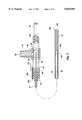
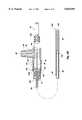
- FIG. 1is a top plan view of a needle-knife assembly where the needle-knife sheath, connecting tube and the needle-knife are disposed within a multi-lumen catheter with the needle-knife retracted in a sheathed position;
- FIG. 1Ais a top plan view of the embodiment of needle-knife assembly shown in FIG. 1, wherein the needle-knife is in a deployed position so that it extends from the distal end of the catheter and needle-knife sheath;
- FIG. 1Bis a side cross-sectional detail view of the distal end of the catheter, catheter sheath and the needle-knife in the deployed position;
- FIG. 1Cis a side cross-sectional view depicting details of the deployment mechanism of the needle-knife actuator assembly, the sheath and the connecting tube;
- FIG. 2is a cross-sectional view of an alternate embodiment of a slidable stop disposed on a needle-knife actuator assembly;
- FIG. 3is a close-up, top view of a deployment mechanism of the needle-knife actuator assembly having another embodiment of the present invention disposed thereon to affirmatively prevent forward advancement of the sliding member beyond a desired position;
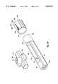
- FIG. 3Ais an exploded view of the body, sliding member and extension regulator of the needle-knife actuator shown in FIG. 3;
- FIG. 3Bis a side cross-sectional view of the embodiment of the present invention shown in FIGS. 3 and 3A, the extension regulator being disposed in a first position in which the sliding member is unable to move a sufficient distance to extend the needle-knife out of the needle-knife sheath;
- FIG. 3Cis a side cross-sectional view of the embodiment of FIGS. 3 and 3A, wherein the extension regulator is disposed in a second position in which the sliding member can slide to fully extend the needle-knife;
- FIG. 4is a top, exploded view of a needle-knife actuator assembly having a modified configuration of the embodiment shown in FIGS. 3 through 3C;
- FIG. 4Ashows a side cross-sectional view of the needle-knife actuation assembly shown in FIG. 4 with the extension regulator disposed on the body of the actuator assembly;
- FIG. 5is a top view of deployment mechanism similar to that shown in the previous figures, but having a plurality of grooves in the end portion, and an extension regulator configured to engagement with the end portion.
- FIG. 6is a top plan view of a deployment mechanism for a catheter carried injection needle, the extension of which is controlled by an extension regulator in accordance with the present invention.
- FIG. 6Ais a top plan view of the deployment mechanism of FIG. 6 with the mechanism positioned to deploy the injection needle;
- FIG. 6Bis a cross-sectional view of the deployment mechanism and catheter of FIG. 6;
- FIG. 7is a top exploded view of an alternate embodiment of the present invention wherein the extension regulator is threadedly engaged to the body of the needle-knife actuator assembly;
- FIG. 7Ais a cross-sectional view of the extension regulator of FIG. 7 being disposed about the end portion of the body of the deployment mechanism;
- FIG. 7Bis a cross-sectional view of the extension regulator of FIG. 7 being disposed about the end portion of the body of the deployment mechanism and being moved in a ratchetting process;
- FIG. 7Cis a cross-sectional view of the extension regulator of FIG. 7 being disposed about the end portion of the body of the deployment mechanism and being slidably moved along the end portion;
- FIG. 7Dis an end view of the extension regulator of FIGS. 7 through 7C and the end portion of the deployment mechanism
- FIG. 8is a top plan view of yet another alternate embodiment of the present invention for use when the sliding member is moved in a plunger-like manner.
- FIG. 9is a top plan view of an alternate embodiment of the present invention for use with sliding members which move in a plunger-like manner.
- FIG. 1there is shown a top plan view of a needle-knife assembly, generally indicated at 10, which is adapted for use with a multi-lumen catheter 12.
- the multi-lumen catheter 12has a connector 14 attached to a proximal end 12a thereof, the connector including a luer lock hub 17 for attachment of the needle-knife assembly.
- a polymeric tube 20which may be used for injection of a contrast medium or some other purpose.
- the needle-knife assembly 10is principally comprised of a deployment mechanism 30 and an elongated sheath 34 having an elongated connecting tube 38 and needle-knife 42 (FIG. 1B) disposed therein.
- the deployment mechanism 30includes a body 50 having a pair of rails 54 which are configured to define a centrally disposed slot 58.
- Body 50includes a first, proximal end 50a to which a thumb ring 62 is attached, and a second, distal end 50b having an end portion 66 at which a fitting 70 (FIG. 1C) is located for receiving the sheath 34 and connecting tube 38 as described below.
- a sliding member 80is slidably connected to the body 50.
- the sliding member 80preferably includes a pair of opposed finger rings 84 which enable a user to grasp the same between two fingers--typically the forefinger and index finger. By placing a thumb through thumb ring 62, the sliding member 80 may be advanced towards the second end 50b of the body 50. As the sliding member 80 moves, it pushes the connecting tube 38 forward and thereby deploys the needle-knife 42. The sliding member 80 may also be freely moved away from the second end 50b of the body 50 until the sliding member contacts a pair of stops 88. When the sliding member 80 is disposed sufficiently toward the first end 50a of the body to contact the stops 88, the connecting tube 38 is moved a sufficient distance to withdraw the needle-knife 42 into the sheath 34 as described below.
- the sliding member 80has an internally disposed brass insert 90 (FIG. 1A) which electrically communicates with a brass binding post 92.
- the brass insert 90 and the brass binding post 92form an electrical connection for coupling a power source (not shown) to the needle-knife 42.
- the power sourceprovides a cutting/coagulating current with which the needle-knife incises tissue.
- the binding post 92is situated within a connector cap 98 integral with the sliding member 80.
- the elongated connecting tube 38is attached to and electrically communicates with the insert 90.
- the connecting tube 38is fabricated from a conductive material, such as stainless steel, and extends through the fitting 70 in the second end 50b of the body 50 and terminates in a distal end 38b.
- the connecting tube 38has a hollow bore (not shown) into which the needle-knife 42 is partially disposed near the distal end 38b.
- the connecting tube 38is crimped over or otherwise attached to the needle-knife 42 at location 100 adjacent the distal end 38b of the connecting tube and in such a manner as to avoid interference with conduction of current through the connecting tube and needle knife.
- the fitting 70tightly receives the elongated tubular sheath 34 and provides strain relief.
- the sheath 34is made from polyimide material with a Teflon coating.
- polyimide materialwith a Teflon coating.
- This combination of materialsenables fabrication of a sheath 34 with an outer diameter as small as approximately 0.035 inches, to enable advancing the same through one lumen of the multi-lumen catheter 12 used in an ERCP procedure in accordance with the present invention.
- the use of polyimide materialprovides good kink resistance, even if the sheath is fabricated with a very thin wall thickness, and the Teflon coating provides a smooth surface to enable the sheath 34 to be easily inserted and removed from the catheter 12.
- FIG. 1Bshows the orientation of the sheath 34 disposed within the catheter 12, where the distal end 34b of the sheath extends a nominal distance from the distal end 12b of the catheter 12.
- the needle-knife 42extends from the distal end 34b of the sheath 34 so that a distal end 42b of the needle-knife is available to incise tissue with the cutting/coagulating current when desired.
- the needle-knife 42has a diameter of approximately 0.006 inches, and is fabricated from a "memory" metal alloy such a Nitonil.
- a "memory" metal alloysuch as Nitonil.
- memory metalsundergo a crystalline phase change and thermoelastically deform when heated and cooled. These crystal phase changes between what are known as high temperature Austenite and low temperature Martensite, enable a component made from such material to contract when heated, and to return to its original configuration when cooled.
- the stress-strain behavior of a memory metal alloymakes the material much easier to deform when cooled (martensite) than when at an elevated temperature (austenite). In the present invention, the use of this material is susceptible to deformation during the cutting procedure.
- the memory materialhelps it return to its original orientation if deformed by stress during the cutting procedure.
- the needle-knife 42is heated by applying the cutting/coagulating current, the crystalline transformation to Austenite makes it much more difficult to deform. If a sufficient force is then applied to the needle-knife 42 during the procedure, the material can strain to relieve the applied stress as it transforms back to Martensite. Once the stress is reduced, it will unstrain and revert back to Austenite. Finally, after the applied current is removed, the resulting cooling of the needle-knife material and associated crystal phase change to Martensite makes it more flexible.
- the needle-knife 42is normally disposed so as to remain in a sheathed position within sheath 34 with respect to the distal end 34b thereof.
- the sheath 34is inserted through lumen 12c of catheter 12 so that the sheath extends to a position at or slightly distal from the distal end 12b of the catheter 12.
- the catheter assemblyis attached to the deployment mechanism 30 by threading the luer lock hub 17 (as shown in FIG. 1) of the connector 14 into the fitting 70 at the second, distal end 50b of the body 50.
- the needle-knife assembly 10is pre-loaded in the catheter 12. This facilitates the use of the needle-knife assembly in a typical ERCP procedure using a multi-lumen catheter.
- the physicianadvances the catheter 12 through an endoscope (as shown in FIG. 4) and into the patient's duodenum proximal to the entrance to the common bile duct, typically into or just above the papillary orifice.
- the physicianadvances the sliding member 80 towards the second end 50b of the body 50 to cause the needle-knife 42 to extend from the distal end 34b of the sheath 34 as shown in FIGS. 1A and 1B.
- the physicianapplies an appropriate amount of cutting/coagulating current to the needle-knife 42 through the binding post 92, and manipulates the needle-knife by using the elevator and/or positioning controls of the endoscope to incise tissue. Typically, a 3-5 millimeter across by 2-4 millimeter deep incision into the papilla is sufficient.
- the needle-knife 42is then retracted into the distal end 34b of the sheath 34 by moving the sliding member 80 rearwardly towards the first end 50a and against the stops 88 of the deployment mechanism 30. This enables the physician to insert the catheter 12 into the common bile duct with less effort.
- the physiciancan then cannulate and visualize the same in accordance with the ERCP procedure described in the foregoing.
- the sheath 34 and needle-knife 42can be left within the first lumen 12c of the catheter 12 to function as a stiffening element to enable advancing the catheter into the common bile duct, or the sheath 34 and needle-knife 42 may be withdrawn from the catheter 12, and a wire guide then inserted in its place by simply unthreading the luer lock hub 17 from deployment mechanism 30 and attaching a wire guide feeding apparatus in a manner known in the art.
- the common bile ductcan then be visualized by infusing a contrast medium through the multi-lumen catheter 12.
- the wire guidemay be advanced along the duct and the catheter 12 then repositioned by advancing the catheter over the wire guide to the appropriate location, and the infusion procedure may be repeated.
- the process of incising the tissue of the sphincter musclerequires precise control of the needle-knife 12.
- the physicianholds the endoscope (not shown) and the catheter 12, and is therefore not able to perform the actuation of the needle-knife 42.
- the physicianmust thus instruct the nurse or other medical professional as to the desired extension of the needle-knife 42 while observing the sphincter muscle through the endoscope.
- the nursemust attempt to repeat the degree of extension at each desired cut location. Such can be extremely difficult and the repeated fine movements of the deployment mechanism 30 can tire the hand of the operator.
- U.S. Pat. No. 5,599,300discloses a slidable stop, substantially the same as slidable stop 104, which is formed by a cylindrical housing disposed on the body 50 adjacent the distal end 50b.
- the slidable stop 104was added to enable the user to customize the range of motion in which the sliding member 80 is moved. Rather than sliding between a first proximal position and a second distal position, the range of motion of the sliding member is limited to movement between the first proximal position, and a third, desired position between the first and second positions.
- the sliding stop 104enables the user to select a desired extension distance V d relative to the distal end 34b of the sheath 34 prior to moving the sliding member 80 towards the second end 50b of the body 50.
- V da desired extension distance relative to the distal end 34b of the sheath 34 prior to moving the sliding member 80 towards the second end 50b of the body 50.
- the slidable stop 104is slid along the body 50 until it contacts the sliding member 80, as indicated at 104a (FIG. 1).
- the slidable stop 104aremains in place, indicating the desired forward position of the sliding member.
- the desired (third) location for stopping the sliding memberis indicated by the slidable stop 104a.
- the slidable stop 104ahas provided an advantage over the customary practice of simply guessing where to stop with each advancement of the sliding member 80, several problems have remained.
- the slidable stop 104is made out of a plastic which slides easily on the plastic body 50.
- the easy sliding of the slidable stop 104facilitates placement so as to mark the forward desired limit of the sliding member 80.
- italso allows the slidable stop to be easily removed from the desired location. Unless the user is careful to stop the sliding member 80 before contacting the slidable stop 104, the slidable stop is nudged forward.
- the needle-knife 42will extend further from the catheter than desired. If the actuation is repeated several times, the difference between actual and desired extension of the needle-knife 42 can be significant.
- slidable stop 104Another problem with the slidable stop 104 is that the the stop will not prevent accidental advancement of the needle-knife. Because the deployment mechanism is held in the user's hand, a simple twitch or other involuntary movement can cause the needle-knife 42 to be deployed to its maximum extent. Such a deployment can incise tissue in the biliary tree or adjacent structures and force emergency surgery.
- FIG. 2shows a cross-sectional view of an alternate embodiment of the present invention which alleviates some of these concerns.
- the embodiment shown in FIG. 2provides a slidable stop 108 which is configured in substantially the same manner as the slidable stop 104 in FIGS. 1, 1A and 1C.
- an under surface of the slidable stopis provided with a friction layer 112 in the form of a coating of material selected to frictionally engage the second end 50b of the body 50. While the friction layer 112 requires more force to move the slidable stop into the desired position when marking the stop point for the sliding member 80, the slidable stop 108 is much more difficult to displace than the slidable stop 104.
- the friction layercould be contoured to provide increased resistance to movement toward the second, distal end 50b of the body 50, than toward the first, proximal end 50a.
- the friction layer 112may be formed of rubber or any of a number of elastomeric materials.
- the friction layer 112may be coated on the entire inner surface of the slidable stop 108, or only on portions which remain in contact with the portion of the body 50 distal from the slot 58.
- the deployment mechanism 30includes an elongate body 50 having a first, proximal end 50a and a second, distal end 50b. Attached to the first, proximal end 50a is the thumb ring 62 which enables the user to maintain a sure grip on the deployment mechanism 30.
- the sliding member 80including the finger rings 84, the binding post 92 and the connecter cap 98, slide along the body 50 between a first, proximal position and a second, distal position.
- an extension regulatorin the form of a slidable stop 120.
- the slidable stop 120has a plurality of channels 124 formed therein.
- the channels 120are preferably disposed in an alternating, spaced relationship.
- a post 128is attached to or formed integrally with the body 50 on the distal end 50b adjacent the slot 58.
- the channels 124are preferably sloped so that when the post 128 is disposed in one of the channels, forward movement of the slidable stop 120 is prevented.
- the channels 124are provided in a staggered arrangement with each slot providing a small advancement of the slidable stop toward the proximal end 50a of the body 50.
- the slidable stop 120includes eight staggered channels which extend from a central channel.
- the movement of the post 128 to an adjacent channelwill advance or contract the maximum extension available by about 1 millimeter (the exact amount of change is dependent on the disposition of the sheath within the patient's body).
- the channels 124also include a terminal channel 124a which is disposed a sufficient distance from the proximal end 120a of the slidable stop 120 that positioning the post 128 within the terminal channel ensures that the needle-knife is retracted into the sheath 34.
- the terminal channel 124amay also include a nub 124b to ensure that the post 128 is not accidentally removed from the terminal channel.
- FIG. 3Also shown in FIG. 3 are a pair of ribs 132 which extend along the slidable stop 120.
- the ribs 132are used to rotate the slidable stop 120 slightly to facilitate movement of the post 128 between the respective channels 124 and thereby adjust the extent to which the needle-knife 42 is able to extend from the sheath 34.
- FIG. 3Athere is shown an exploded view of the body 50, the sliding member 80 and the extension regulator in the form of a slidable stop 120.
- the body 50is formed by an elongate piece of plastic having the first, proximal end 50a and the second, distal end 50b with a slot 58 defined by opposing rails 54.
- the sliding member 80is slidably mounted over the body 50. Because of the post 128, the sliding member 80 is typically slid over the proximal end 50a of the body 50.
- the thumb ring(not shown in FIG. 3A) in attached to the proximal end 50a of the body 50, the sliding member 80 is locked between the thumb ring and the post 128.
- the insert 90When the insert 90 is placed into the sliding member 80, the insert engages the stops 88 formed on the rails, and thereby limits proximal movement of the sliding member 80.
- the slidable stop 120is typically provided with an open end 124d at the base of the channels 124 to enable the slidable stop to be mounted on the body 50 by simply sliding the stop over the distal end 50b of the body while the open end is in alignment with the post 128.
- the polymeric tube 20will generally prevent the slidable stop 120 from sliding off the body.
- the channels 124could be formed without an open end, and the slidable stop 120 could be configured to deform sufficiently to slide over the post 128 for initial placement.
- FIG. 3Bis a side cross-sectional view of the embodiment of the present invention shown in FIG. 3, the slidable stop 120 regulating extension of the needle-knife 42 disposed in a first position in which the sliding member 80 is unable to move a sufficient distance to extend the needle-knife out of the needle-knife sheath 34.
- the post 128is nested in the terminal channel 124a, and thereby holds the slidable stop 120 adjacent its most proximal position. With the slidable stop 120 in such a position, the physician can freely move the needle-knife sheath 34 without risk of the needle-knife 42 damaging the duct in which the catheter is disposed.
- the present inventionprovides a simple yet effective way to ensure safety during advancement or withdrawal of the catheter/sheath.
- FIG. 3Cis a side cross-sectional view of the embodiment of FIG. 3, wherein the slidable stop 120 which regulates extension of the needle-knife 42 is disposed in a second, distal position in which the sliding member 80 can slide to fully extend the needle-knife 42.
- the post 128must be disposed adjacent to the proximal end 120a of the stop 120 so that the stop does not extend beyond the proximal end 66a of the end portion 66.
- the stop 120provides no barrier to movement of the sliding member 80 into its second, distal position, thereby achieving maximum extension of the needle-knife 42.
- the user of the deployment mechanism 30is able to more accurately determine the extent to which the needle-knife 42 will extend from the sheath 32 with each actuation.
- the slidable stop 120is easy to use and provides a much safer application of the electro-surgical instrument than the prior art method of repeatedly guessing where to stop advancement of the device. Because the desired location is determined and the slidable stop 120 is locked into place, the procedure may occur more rapidly without any increased risk to the patient.
- FIG. 4there is shown a top, exploded view of the deployment mechanism 30 of a needle-knife actuator assembly having a modified configuration of the embodiment shown in FIGS. 3 through 3C.
- the embodiment shown in FIG. 4has a plurality of grooves 134 formed in the end portion.
- a cylindrical housing forming a slidable stop 140is provided with a downwardly extending post 144 which is configured to nest within the grooves 134.
- the slidable stopis preferably made of a transparent material to enable the user to see the post 144.
- the post 114could be colored to further enhance visibility.
- the usercan control the position of the slidable stop 140 in such a manner as to regulate the distance the sliding member 80 can slide toward the distal end 50b of the body 50. Because the reversal between the position of the post 144 and the grooves 134, the grooves will typically have the opposite orientation as when they are formed in the housing of the stop 120 (FIG. 3A).
- Such control of the sliding member 80controls the extent to which the needle-knife 42 is extendable out of the sheath 34.
- the slidable stop 140When the post 144 of the slidable stop 140 is disposed in the proximal most groove 134a, the slidable stop 140 is positioned in its most proximal position. In such a position, the slidable stop 140 prevents the sliding member 80 from sliding forwardly a sufficient distance to extend the needle-knife 42 from the sheath 34.
- Each groove 134 distal from the proximal most groove 134aprovides one step in a series of controlled extension steps.
- the physician viewing the extension of the needle-knifecan instruct the user to proceed to the next step until a desired extension is obtained. Typically, this will occur in 0.5 to 1 millimeter increments.
- the useris able to simply actuate the deployment mechanism 30 to extend the needle-knife without guess work and without concern of accidental overextension.
- FIG. 4Ashows a side cross-sectional view of the deployment mechanism 30 of a needle-knife actuation assembly shown in FIG. 4.
- the slidable stop 140 forming the extension regulatoris disposed on the body 50 so that it is between a first, extreme proximal position wherein the slidable stop 140 would stop any extension of the needle-knife 42 outside the sheath 34, and a second, extreme distal position wherein the slidable stop would allow complete extension of the needle-knife.
- FIG. 5there is shown an exploded view of yet another embodiment of the present invention.
- the deployment mechanism 30is substantially the same as those discussed in preceding embodiments and is numbered accordingly.
- the primary difference between the deployment mechanism 30 of FIG. 5is that a plurality of grooves 152 are formed in the body 50 in the end portion 66.
- an extension regulator 154in the form of a generally C-shaped clip.
- the extension regulator 154has a plurality of raised ribs 158 which are configured to mate within the grooves 152 in the end portion 66 of the body 50.
- the grooves 152 and ribs 158are preferably small enough to allow relatively fine adjustments in where the extension regulator 154 is positioned.
- the extension regulator 154is formed by a generally C-shaped body having a plurality of protruding ribs 158 which are used to engage the grooves 152 on the body 50 of the deployment device 30.
- a pair of tabs 162extend outwardly from the C-shaped body of the extension regulator 154. Squeezing the tabs 162 together deflects the C-shaped body outwardly and enables the protruding ribs 158 to be removed easily from the grooves 152.
- the extension regulator 154can then be moved to a new location and the tabs 162 released, thereby locking the extension regulator in new desired position.
- FIGS. 6 and 6Athere is shown a top, plan view of an actuation assembly, generally indicated at 200, for a controlling extension of an injection needle 204 from the distal end 208b of a catheter 208 in which the injection needle is carried.
- an electro-surgical instrumentsuch as a needle-knife
- the needlemay be used, for example, to inject a chemotherapy drug into a tumor, or to apply medication to a particular location without having to subject the remainder of the patient's body to the drug.
- the physicianadvances the needle out of the catheter so that the needle-tip penetrates the desired object.
- a syringeis then used to inject a fluid through the needle. Requiring the physician to repeatedly move the injection needle by manipulation of the catheter or a sheath can be cumbersome and can slow the rate of the procedure. If a deployment device were provided, the user could deploy the injection needle whenever desired, and then retract the needle without having to move the entire needle assembly with respect to the catheter.
- the actuator assembly 200includes a deployment mechanism 220 and an elongated injection tube 224 for connecting the injection needle 204 to a syringe 228.
- the deployment mechanism 220includes an elongate body 250.
- the elongate body 250has a pair of rails 254 which are configured to define a centrally disposed slot 258.
- Body 250also includes a first, proximal end 250a with a thumb ring 262 attached thereto, and a second, distal end 250b having an end portion 266 at which a fitting 270 is located for receiving the injection tube 224.
- a sliding member 280is slidably connected to the body 250.
- the sliding member 280preferably includes a pair of opposed finger rings 284 which enable a user to grasp the same between two fingers, typically the forefinger and index finger. By placing a thumb through thumb ring 262, the sliding member 280 may be advanced towards the second end 250b of the body 250. As the sliding member 280 moves, it pushes the injection tube 224 forward and thereby deploys the injection needle 204. The sliding member 280 may also be freely moved away from the second end 250b of the body 250 until the sliding member contacts a pair of stops 288 disposed along the rails 254, thereby withdrawing the injection needle 204 into the catheter 208.
- an extension regulator 290is disposed on the deployment mechanism 220.
- the extension regulator 290is moveable between a first, extreme proximal position, in which the extension regulator prevents distal movement of the sliding member 280, and a second, extreme distal position, in which the extension regulator does not interfere with distal movement of the sliding member.
- the extension regulatoris a cylindrical housing having threads on an inner wall thereof to threadedly engage the end portion 266.
- the extension regulatoris rotated. If rotated in a first direction, the extension regulator 290 moves generally proximally and eventually reaches the first, extreme proximal position wherein the extension regulator prevents distal movement of the sliding member 280. If the extension regulator 290 is rotated in the opposite direction, the extension regulator moves toward the second, extreme distal position wherein it provides no interference to the movement of the sliding member 280. Between the two, the extension regulator defines a third position to control the amount of extension of the injection needle 204.
- FIG. 6B1there is shown a side cross-sectional view of the deployment device 220.
- the extension regulator 290has been rotated so that a proximal end 290a thereof is disposed at a third position, between the first and second positions, to thereby stop the distal movement of the sliding member 280.
- the extension regulatorlimits the extent to which the injection needle 204 may be advanced out of the catheter.
- the physicianis able to better control the injection needle 204 and obtain desired needle placement.
- FIG. 7there is shown top view of the deployment mechanism 30 and an alternate embodiment of an extension regulator 170, made in accordance with the present invention.
- the deployment mechanism 30is substantially the same as that described with respect to FIGS. 1 through 5A and is numbered accordingly.
- the only difference between the deployment mechanism 30 and those discussed with respect to FIGS. 1 through 5Ais that the end portion 66 of the body 50 has helical threads 174 which circumscribe the end portion.
- the extension regulator 170in contrast, is significantly different than those discussed above. Namely, the extension regulator 170 is configured to enable selective movement thereof by sliding, ratcheting, and/or rotation of the extension regulator into the desired position. These various mechanisms are accomplished by a C-shaped housing 178, the interior of which is unthreaded, and a ratcheting flange 182 which is pivotably connected to the housing 178 so that the housing and the flange form a substantially cylindrical body.
- the flange 182has threads 186 which engage the helical threads 174 of the end portion 66 to enable the position of the extension regulator 170 to be adjusted by rotating the housing 178 about the end portion.
- the flange 182also is spring-loaded and the threads 186 on the flange and the threads 174 on the end portion 66 will interact to permit sliding of the extension regulator 170 in one direction with relative ease, while inhibiting sliding of the extension regulator 170 in the opposite direction. Furthermore, the flange 182 may be pivoted so that the threads 186 are no longer in engagement with the threads 174 of the end portion 66 to facilitate rapid movement of the extension regulator in either direction.
- FIG. 7Athere is shown a close-up view of the extension regulator 170 disposed about the end portion 66 of the body 50 of the deployment mechanism 30, the remainder of which is not shown.
- the end portion 66is provided with a plurality of threads 174 which are disposed helically.
- the threads 174have two faces which are at significantly different slopes.
- the threads 174have a first, proximal face 174a which is disposed at a steep angle, such as 70 or 80 degrees.
- the threads 174also have a second, distal face 174b which is disposed at a much lesser angle, such as 30 degrees.
- the flange 182is the only portion of the extension regulator 170 which is threaded. Like the threads 174 on the end portion 66, one face of the threads 186 of the extension regulator 170 has a steep angle, while the opposing face has a much more gradual slope. On the flange 182, however, the gradual slope (i.e. about 30 degrees) is disposed on the first, proximal face 186a so that it engages the gradual slope of the second, distal face 174b of the threads 174 on the end portion 66. Likewise, the second, distal face 186b of the threads 186 on the flange 182 are steeply angled (i.e. 70 to 80 degrees) and engage the steeply angled proximal face 174a of the threads 174 of the end portion 66.
- first, proximal face 186a of the flange 182 and the second, distal face 174b of the end portion 66enable these two faces to slide with respect to each other.
- application of force to the extension regulator 170 in a proximal direction, as indicated by arrow 190,causes the flange 182 to be deflected upwardly a small amount.
- the deflection of the flange 182enables the extension regulator 170 to slide proximally the distance of 1 thread, as shown in FIG. 7B.
- the spring 192will force the threads 186 of the flange into a mating engagement with the threads 174 of the end portion 66, the extension regulator 170 having advanced the distance of one thread. By applying a small amount of pressure, the extension regulator can thus be ratcheted in a proximal direction and into engagement with the slide member 80.
- extension regulatorcan be ratcheted in the proximal direction, it generally cannot be ratcheted in the distal direction.
- the steeply angled distal faces 186b of the threads 186 of the flange 182engage the steeply angled proximal faces 174a of the threads 174 of the end portion 66.
- the steep facesprovide significant resistance to horizontal movement in the distal direction.
- the flange 182is disposed in the position shown in FIG. 7A, the only feasible mechanism for distal movement of the extension regulator 170 is to rotate it in the proper direction.
- FIG. 7Cthe is shown a cross-sectional view of the end portion 66 and the extension regulator 170.
- the flange 182has been pivoted so that its threads 186 are no longer engaged with the threads 174 of the end portion 66. Because the housing 178 of the extension regulator 170 is not threaded, disengaging the threads 186 of the flange 182 from the threads 174 of the end portion 66 enables the extension regulator to slide freely in either direction. Once the flange 186 is returned to a horizontal position, as shown in the end view of FIG.
- FIGS. 8 and 9there are shown two additional applications of the present invention.
- a actuator assemblyfor controllably deploying a medical instrument, such as a biopsy device 304, which is disposed adjacent the distal end 308b of a catheter 308.
- the catheter 308is attached at a proximal end 308a to a deployment mechanism 312 by a luer lock 314.
- the deployment mechanism 312includes a base 320 in the form of a generally hollow body 324 with a pair of finger rings 328.
- a sliding member 332 in the form of a plungeris slidable between a first, extended, proximal position and a second, inserted, distal position.
- the sliding member 332is attached to the biopsy device 304 by an elongate connector 336 which extends through a lumen of the catheter 308. With the sliding member 332 disposed in the proximal position, as shown in FIG. 8, the biopsy device will be withdrawn in the catheter 308. (In FIG. 8 the biopsy device is extended despite the position of the sliding member 332 simply show the extent to which it will typically extend from the catheter).
- stops 338Disposed along the sliding member 332 are a plurality of stops 338.
- the stops 338are staggered in a helical pattern about the sliding member 332 and are sufficiently small that they can slide into the base 320.
- a blocking wall 340is disposed on one side of the base 320 so that the distal movement of the plunger is stopped when one of the stops 338 contacts the wall.
- the usercan select which of the stops 338 contacts the blocking wall 340.
- the plungeris rotated so that stop 338a contacts the wall 340 when the sliding member is moved distally.
- the sliding member 332is rotated so that the stop 338c contacts the wall.
- An intermediate positionis provided by stop 338b.
- the connector 336is nested in the rotatable attachment 342 which connects the thumb ring 344 to the sliding member 332. As the sliding member rotates, the thumb ring 344 can be held stable, thereby preventing torque in the connector 336.
- the useris able to limit the distal range of motion of the sliding member to a third, desired position.
- Limiting the distal movement of the sliding member 332limits the distance which the biopsy device 304 can extend from the catheter 308, thereby providing the physician with improved control over deployment of the biopsy device. While only three stops 338 are shown in FIG. 8, numerous stops could be used to provide a greater number of stopping locations.
- FIG. 9shows an embodiment which is somewhat to that shown in FIG. 8.
- the deployment mechanism 312is used for activation of a bow-knife 384 disposed at the distal end 308'b of the catheter.
- the use of a bow-knifeis typically for purposes similar to those which use a needle-knife, namely incising tissue. In the process of incising the tissue, it is important to control the distance which the electro-surgical elements 386 extends outwardly from the catheter.
- most aspects of the deployment mechanism 312are the same as discussed with respect to FIG. 8 and are therefore numbered accordingly.
- a binding post 390 similar to those discussed with respect to the needle-knifeis provided on the sliding member 388.
- the deployment mechanism 312is used in the exact opposite manner with a bow-knife.
- the electro-surgical elementis moved proximally. This causes the distal end 308'b of the catheter to bow and thereby spaces the element from the catheter for cutting.
- the extension regulator of this embodimentactually limits withdrawal of the sliding member from the base.
- the sliding member 388 of FIG. 9does not rotate. Rather, a plurality of spring-loaded stops 348 are disposed in one of the rails 350 of the sliding member 388. Each stop 348 is attached to a control button 354. Pressing the control button 354 of a particular stop 348 releases the stop so that it extends outwardly from the sliding member 388 as indicated at stop 348a. The distance which the stop 348a extends beyond the rail 350 is sufficient to prevent the any portion of the sliding member 388 distal thereto from leaving the base 320.
- the usercan limit the ability of the sliding member 388 to advance proximally out of the base 320 and thereby control the bow-knife 384 at the distal end 308'b of the catheter 308'.
- the method usedwill enable the user to return the stop 348 to its original position. In such a manner, the accidental release of a stop 348 will not interfere with continued use of the deployment mechanism 312.
- the medical devicewhich may be so controlled can include virtually any medical instrument which can be deployed from and retracted into the distal end of the catheter.
- physicians and other medical professionalscan be relieved from the guess work which is commonly associated with deployment of medical instruments from catheters, and accidental lacerations, incisions and other damage to ducts should be reduced.
Landscapes
- Health & Medical Sciences (AREA)
- Life Sciences & Earth Sciences (AREA)
- Engineering & Computer Science (AREA)
- Veterinary Medicine (AREA)
- General Health & Medical Sciences (AREA)
- Surgery (AREA)
- Biomedical Technology (AREA)
- Heart & Thoracic Surgery (AREA)
- Public Health (AREA)
- Animal Behavior & Ethology (AREA)
- Physics & Mathematics (AREA)
- Otolaryngology (AREA)
- Biophysics (AREA)
- Cardiology (AREA)
- Pulmonology (AREA)
- Plasma & Fusion (AREA)
- Nuclear Medicine, Radiotherapy & Molecular Imaging (AREA)
- Hematology (AREA)
- Anesthesiology (AREA)
- Medical Informatics (AREA)
- Molecular Biology (AREA)
- Media Introduction/Drainage Providing Device (AREA)
- Surgical Instruments (AREA)
- Laser Surgery Devices (AREA)
Abstract
Description
Claims (48)
Priority Applications (1)
| Application Number | Priority Date | Filing Date | Title |
|---|---|---|---|
| US08/794,162US5843091A (en) | 1995-05-12 | 1997-02-03 | Extension regulator for catheter carried medical instruments |
Applications Claiming Priority (2)
| Application Number | Priority Date | Filing Date | Title |
|---|---|---|---|
| US08/440,562US5599300A (en) | 1992-05-11 | 1995-05-12 | Method for electrosurgically obtaining access to the biliary tree with an adjustably positionable needle-knife |
| US08/794,162US5843091A (en) | 1995-05-12 | 1997-02-03 | Extension regulator for catheter carried medical instruments |
Related Parent Applications (1)
| Application Number | Title | Priority Date | Filing Date |
|---|---|---|---|
| US08/440,562Continuation-In-PartUS5599300A (en) | 1992-05-11 | 1995-05-12 | Method for electrosurgically obtaining access to the biliary tree with an adjustably positionable needle-knife |
Publications (1)
| Publication Number | Publication Date |
|---|---|
| US5843091Atrue US5843091A (en) | 1998-12-01 |
Family
ID=23749254
Family Applications (2)
| Application Number | Title | Priority Date | Filing Date |
|---|---|---|---|
| US08/440,562Expired - LifetimeUS5599300A (en) | 1992-05-11 | 1995-05-12 | Method for electrosurgically obtaining access to the biliary tree with an adjustably positionable needle-knife |
| US08/794,162Expired - LifetimeUS5843091A (en) | 1995-05-12 | 1997-02-03 | Extension regulator for catheter carried medical instruments |
Family Applications Before (1)
| Application Number | Title | Priority Date | Filing Date |
|---|---|---|---|
| US08/440,562Expired - LifetimeUS5599300A (en) | 1992-05-11 | 1995-05-12 | Method for electrosurgically obtaining access to the biliary tree with an adjustably positionable needle-knife |
Country Status (6)
| Country | Link |
|---|---|
| US (2) | US5599300A (en) |
| JP (1) | JP3753738B2 (en) |
| AU (1) | AU5857696A (en) |
| BR (1) | BR9608135A (en) |
| CA (1) | CA2220683C (en) |
| WO (1) | WO1996035470A1 (en) |
Cited By (42)
| Publication number | Priority date | Publication date | Assignee | Title |
|---|---|---|---|---|
| US5993462A (en)* | 1996-07-15 | 1999-11-30 | Cardiac Pathways Corporation | Shapable catheter using exchangeable core and method of use |
| US6162209A (en)* | 1998-11-17 | 2000-12-19 | Scimed Life Systems, Inc. | Multi-function surgical instrument tool actuator assembly |
| US6210398B1 (en)* | 1998-05-28 | 2001-04-03 | Asahi Kogaku Kogyo Kabushiki Kaisha | Manipulating part of endoscopic treatment tool |
| US6533782B2 (en) | 2000-05-18 | 2003-03-18 | Wilson-Cook Medical Incorporated | Medical device with improved wire guide access |
| US6770066B1 (en) | 1992-05-11 | 2004-08-03 | Ballard Medical Products | Multi-lumen endoscopic catheter |
| US20040243023A1 (en)* | 2003-05-30 | 2004-12-02 | Grigoryants Sergey S | Transbronchial needle aspiration device |
| US20040267164A1 (en)* | 2003-06-26 | 2004-12-30 | Rhodes James M. | Surgical instrument |
| US20050228225A1 (en)* | 2001-10-12 | 2005-10-13 | Hauschild Sidney F | Method of injecting a drug and echogenic bubbles into prostate tissue |
| US20060229633A1 (en)* | 2005-04-08 | 2006-10-12 | Shepherd David J | Methods and apparatus for inserting an intraocular lens into an eye |
| US20060229634A1 (en)* | 2005-04-08 | 2006-10-12 | Shepherd David J | Methods and apparatus for inserting an intraocular lens into an eye |
| US20070088354A1 (en)* | 2005-10-19 | 2007-04-19 | Pentax Corporation | High-Frequency Incision Instrument For Endoscope |
| US20070156222A1 (en)* | 2005-12-29 | 2007-07-05 | Feller Frederick Iii | Adjustable and detached stent deployment device |
| US20080188920A1 (en)* | 2007-02-02 | 2008-08-07 | Boston Scientific Scimed, Inc. | Medical systems and related methods |
| US20080228258A1 (en)* | 2007-02-05 | 2008-09-18 | Boston Scientific Scimed, Inc. | Medical systems and related components and methods |
| US20080234662A1 (en)* | 2004-12-31 | 2008-09-25 | Artifon Everson Luiz De Almelda | Constructive Disposal Placed in Artifon Catheter Applied in Perforations Above the Papillae in Fistula-Papillotomy |
| US20090005637A1 (en)* | 2001-09-27 | 2009-01-01 | Scimed Life Systems, Inc. | Method and Apparatus for Measuring and Controlling Blade Depth of a Tissue Cutting Apparatus in an Endoscopic Catheter |
| EP1990018A3 (en)* | 2007-05-07 | 2009-01-21 | Olympus Medical Systems Corp. | Endoscopic instrument |
| US20100022837A1 (en)* | 2007-04-20 | 2010-01-28 | Tsutomu Ishiguro | Surgical instrument and endoscope surgical system having surgical instrument |
| US20110184429A1 (en)* | 2010-01-27 | 2011-07-28 | Saldinger Pierre F | Surgical device |
| US8177760B2 (en) | 2004-05-12 | 2012-05-15 | C. R. Bard, Inc. | Valved connector |
| ITTO20110309A1 (en)* | 2011-04-05 | 2012-10-06 | Igea S P A | ADJUSTABLE HANDPIECE |
| US20130296891A1 (en)* | 2012-05-04 | 2013-11-07 | Covidien Lp | Surgical clip applier with dissector |
| US8784468B2 (en) | 2010-11-17 | 2014-07-22 | Boston Scientific Scimed, Inc. | Stent delivery systems and locking members for use with stent delivery systems |
| US9084692B2 (en) | 2010-11-17 | 2015-07-21 | Boston Scientific Scimed, Inc. | Stent delivery system |
| USD746442S1 (en)* | 2012-05-03 | 2015-12-29 | Sofic | Safety syringe |
| US9220619B2 (en) | 2010-11-17 | 2015-12-29 | Boston Scientific Scimed, Inc. | Stent delivery system |
| US20160310210A1 (en)* | 2013-12-12 | 2016-10-27 | Holaira, Inc. | Catheter and handle assembly, systems, and methods |
| US20170333118A1 (en)* | 2016-05-17 | 2017-11-23 | Alan Ellman | Depth control for electrosurgical electrode |
| US9877854B2 (en) | 2014-05-21 | 2018-01-30 | Boston Scientific Scimed, Inc. | Stent delivery system |
| WO2018040061A1 (en)* | 2016-09-02 | 2018-03-08 | 杭州安杰思医学科技有限公司 | Tissue incision device for endoscope |
| WO2018112221A1 (en)* | 2016-12-16 | 2018-06-21 | Boston Scientific Scimed, Inc. | Medical device handles and related methods |
| US10058443B2 (en) | 2011-11-02 | 2018-08-28 | Boston Scientific Scimed, Inc. | Stent delivery systems and methods for use |
| US10159587B2 (en) | 2015-01-16 | 2018-12-25 | Boston Scientific Scimed, Inc. | Medical device delivery system with force reduction member |
| US10939805B2 (en) | 2017-09-25 | 2021-03-09 | Broncus Medical Inc. | Medical appliance for controlling medical device through catheter sheath based on pneumatic action |
| US11013627B2 (en) | 2018-01-10 | 2021-05-25 | Boston Scientific Scimed, Inc. | Stent delivery system with displaceable deployment mechanism |
| US11065137B2 (en) | 2016-02-26 | 2021-07-20 | Boston Scientific Scimed, Inc. | Stent delivery systems with a reduced profile |
| US11285301B2 (en) | 2016-04-17 | 2022-03-29 | Acantha Medical, LLC | Device and method for single-handed access and insertion of an article |
| US11351048B2 (en) | 2015-11-16 | 2022-06-07 | Boston Scientific Scimed, Inc. | Stent delivery systems with a reinforced deployment sheath |
| US11413433B2 (en) | 2016-04-17 | 2022-08-16 | Acantha Medical, LLC | Device and method for single-handed access and insertion of an article |
| US11602447B2 (en) | 2019-02-13 | 2023-03-14 | Boston Scientific Scimed Inc. | Stent delivery systems |
| EP4045124A4 (en)* | 2019-10-15 | 2024-01-24 | Sofregen Medical, Inc. | Delivery devices for delivering and methods of delivering compositions |
| US12048818B2 (en) | 2020-07-05 | 2024-07-30 | New Wave Endo-Surgical Corp. | Handheld elongate medical device advancer and related systems, devices and methods |
Families Citing this family (109)
| Publication number | Priority date | Publication date | Assignee | Title |
|---|---|---|---|---|
| US6743217B2 (en) | 1994-05-13 | 2004-06-01 | Scimed Life Systems, Inc. | Apparatus for performing diagnostic and therapeutic modalities in the biliary tree |
| US5547469A (en) | 1994-05-13 | 1996-08-20 | Boston Scientific Corporation | Apparatus for performing diagnostic and therapeutic modalities in the biliary tree |
| ATE440559T1 (en) | 1995-10-13 | 2009-09-15 | Medtronic Vascular Inc | DEVICE FOR INTERSTITIAL TRANSVASCULAR PROCEDURES |
| US6375615B1 (en) | 1995-10-13 | 2002-04-23 | Transvascular, Inc. | Tissue penetrating catheters having integral imaging transducers and their methods of use |
| DE69633411T2 (en) | 1995-10-13 | 2005-10-20 | Transvascular, Inc., Menlo Park | METHOD AND DEVICE FOR PREVENTING ARTERIAL ATTRACTIONS AND / OR FOR CARRYING OUT OTHER TRANSVASCULAR INTERVENTIONS |
| US6283951B1 (en)* | 1996-10-11 | 2001-09-04 | Transvascular, Inc. | Systems and methods for delivering drugs to selected locations within the body |
| US6302875B1 (en)* | 1996-10-11 | 2001-10-16 | Transvascular, Inc. | Catheters and related devices for forming passageways between blood vessels or other anatomical structures |
| US6346093B1 (en) | 1996-09-13 | 2002-02-12 | Scimed Life Systems, Inc. | Single operator exchange biliary catheter with common distal lumen |
| US6007522A (en)* | 1996-09-13 | 1999-12-28 | Boston Scientific Corporation | Single operator exchange biliary catheter |
| US6096009A (en)* | 1996-09-13 | 2000-08-01 | Boston Scientific Corporation | Guidewire and catheter locking device and method |
| US5921971A (en) | 1996-09-13 | 1999-07-13 | Boston Scientific Corporation | Single operator exchange biliary catheter |
| US6520951B1 (en) | 1996-09-13 | 2003-02-18 | Scimed Life Systems, Inc. | Rapid exchange catheter with detachable hood |
| US6582401B1 (en) | 1996-09-13 | 2003-06-24 | Scimed Life Sytems, Inc. | Multi-size convertible catheter |
| US6606515B1 (en) | 1996-09-13 | 2003-08-12 | Scimed Life Systems, Inc. | Guide wire insertion and re-insertion tools and methods of use |
| US6379319B1 (en) | 1996-10-11 | 2002-04-30 | Transvascular, Inc. | Systems and methods for directing and snaring guidewires |
| AU9681198A (en) | 1997-10-03 | 1999-04-27 | Boston Scientific Corporation | Device and method for facilitating access to a duct within the human body |
| US6669643B1 (en) | 1998-04-13 | 2003-12-30 | Theodore J. Dubinsky | Method and apparatus for sonographic examination, biopsy, and excision |
| US7214229B2 (en) | 1999-03-18 | 2007-05-08 | Fossa Medical, Inc. | Radially expanding stents |
| US6709465B2 (en) | 1999-03-18 | 2004-03-23 | Fossa Medical, Inc. | Radially expanding ureteral device |
| US6228071B1 (en)* | 1999-04-16 | 2001-05-08 | Heartport, Inc. | Devices and methods for cannulating a blood vessel |
| EP1185200B1 (en) | 1999-06-05 | 2008-01-09 | Wilson-Cook Medical Inc. | Indicia for an endoscopic medical device |
| US6602250B2 (en) | 2000-01-31 | 2003-08-05 | Wilson-Cook Medical Incorporated | Echogenic wire knife |
| US7811250B1 (en) | 2000-02-04 | 2010-10-12 | Boston Scientific Scimed, Inc. | Fluid injectable single operator exchange catheters and methods of use |
| WO2001074260A1 (en)* | 2000-03-24 | 2001-10-11 | Johns Hopkins University | Peritoneal cavity device and method |
| US7520877B2 (en)* | 2000-06-07 | 2009-04-21 | Wisconsin Alumni Research Foundation | Radiofrequency ablation system using multiple prong probes |
| ATE308935T1 (en)* | 2000-08-14 | 2005-11-15 | Boston Scient Ltd | DIRECTORABLE SPHINCTEROTOME |
| US6572629B2 (en) | 2000-08-17 | 2003-06-03 | Johns Hopkins University | Gastric reduction endoscopy |
| ATE427133T1 (en)* | 2000-11-03 | 2009-04-15 | Cleveland Clinic Foundation | CATHETER FOR REMOVING SOLIDS FROM SURGICAL DRAINS |
| US6579300B2 (en) | 2001-01-18 | 2003-06-17 | Scimed Life Systems, Inc. | Steerable sphincterotome and methods for cannulation, papillotomy and sphincterotomy |
| US20030097169A1 (en)* | 2001-02-26 | 2003-05-22 | Brucker Gregory G. | Bifurcated stent and delivery system |
| WO2002067816A1 (en)* | 2001-02-26 | 2002-09-06 | Scimed Life Systems, Inc. | Bifurcated stent and delivery system |
| US6695877B2 (en) | 2001-02-26 | 2004-02-24 | Scimed Life Systems | Bifurcated stent |
| US6764484B2 (en)* | 2001-03-30 | 2004-07-20 | Scimed Life Systems, Inc. | C-channel to o-channel converter for a single operator exchange biliary catheter |
| US6814739B2 (en)* | 2001-05-18 | 2004-11-09 | U.S. Endoscopy Group, Inc. | Retrieval device |
| US6827718B2 (en) | 2001-08-14 | 2004-12-07 | Scimed Life Systems, Inc. | Method of and apparatus for positioning and maintaining the position of endoscopic instruments |
| US7083630B2 (en)* | 2002-08-29 | 2006-08-01 | Scimed Life Systems, Inc. | Devices and methods for fastening tissue layers |
| US6893393B2 (en)* | 2003-02-19 | 2005-05-17 | Boston Scientific Scimed., Inc. | Guidewire locking device and method |
| WO2004084712A1 (en)* | 2003-03-25 | 2004-10-07 | Olympus Corporation | Guide wire |
| WO2004098654A2 (en)* | 2003-05-02 | 2004-11-18 | Metolius Biomedical, Llc | Body-space drainage-tube debris removal |
| US8211087B2 (en)* | 2003-07-31 | 2012-07-03 | Cook Medical Technologies Llc | Distal wire stop |
| US20050070821A1 (en)* | 2003-07-31 | 2005-03-31 | Deal Stephen E. | System and method for introducing a prosthesis |
| EP1682014A4 (en) | 2003-10-14 | 2010-11-17 | Pluromed Inc | Confinement of kidney-stone fragments during lithotripsy |
| US20050125050A1 (en)* | 2003-12-04 | 2005-06-09 | Wilson Cook Medical Incorporated | Biliary stent introducer system |
| EP2286863A3 (en)* | 2004-01-09 | 2011-03-23 | Corazon Technologies, Inc. | Multilumen catheters and methods for their use |
| US20050273150A1 (en)* | 2004-03-31 | 2005-12-08 | Howell Douglas D | Stent introducer system |
| WO2006015323A2 (en)* | 2004-07-29 | 2006-02-09 | Wilson-Cook Medical Inc. | Catheter with splittable wall shaft and peel tool |
| JP4901087B2 (en)* | 2004-09-24 | 2012-03-21 | オリンパス株式会社 | Stent introduction member, stent delivery catheter, and endoscope treatment system |
| US20060111704A1 (en)* | 2004-11-22 | 2006-05-25 | Rox Medical, Inc. | Devices, systems, and methods for energy assisted arterio-venous fistula creation |
| JP2008523908A (en)* | 2004-12-15 | 2008-07-10 | ウィルソン−クック・メディカル・インコーポレーテッド | Minimally invasive medical device with a spiral pattern for displaying travel distance |
| US8480629B2 (en)* | 2005-01-28 | 2013-07-09 | Boston Scientific Scimed, Inc. | Universal utility board for use with medical devices and methods of use |
| ES2529130T3 (en) | 2005-05-02 | 2015-02-17 | Genzyme Corporation | Non-lithotropic kidney stone therapy |
| JP4772386B2 (en)* | 2005-06-07 | 2011-09-14 | オリンパスメディカルシステムズ株式会社 | Submucosal layer peeling treatment tool set and submucosal layer peeling treatment tool system |
| WO2006129726A1 (en) | 2005-05-31 | 2006-12-07 | Olympus Medical Systems Corp. | Device and method for mucosal detachment |
| US20070014945A1 (en)* | 2005-07-12 | 2007-01-18 | Boston Scientific Scimed, Inc. | Guidewire with varied lubricity |
| US8435284B2 (en)* | 2005-12-14 | 2013-05-07 | Boston Scientific Scimed, Inc. | Telescoping bifurcated stent |
| US8343211B2 (en)* | 2005-12-14 | 2013-01-01 | Boston Scientific Scimed, Inc. | Connectors for bifurcated stent |
| US20070208414A1 (en)* | 2006-03-06 | 2007-09-06 | Shawn Sorenson | Tapered strength rings on a bifurcated stent petal |
| US20070233233A1 (en)* | 2006-03-31 | 2007-10-04 | Boston Scientific Scimed, Inc | Tethered expansion columns for controlled stent expansion |
| US20070265595A1 (en)* | 2006-05-09 | 2007-11-15 | Olympus Medical Systems Corp. | Treatment tool inserting/withdrawing auxiliary device and medical procedure through endoscope |
| WO2008030886A1 (en)* | 2006-09-06 | 2008-03-13 | Cardiofirst | Guidance system used in treating chronic occlusion |
| WO2008042756A2 (en)* | 2006-09-29 | 2008-04-10 | Pluromed, Inc. | Methods for preventing retropulsion of concretions and fragments during lithotripsy |
| US7766909B2 (en)* | 2006-11-08 | 2010-08-03 | Boston Scientific Scimed, Inc. | Sphincterotome with stiffening member |
| WO2008085712A1 (en) | 2007-01-03 | 2008-07-17 | Boston Scientific Limited | Method and apparatus for biliary access and stone retrieval |
| US20080167628A1 (en)* | 2007-01-05 | 2008-07-10 | Boston Scientific Scimed, Inc. | Stent delivery system |
| EP2120674B1 (en) | 2007-02-12 | 2016-06-29 | Boston Scientific Limited | Endoscope cap |
| US20090062769A1 (en)* | 2007-04-13 | 2009-03-05 | Boston Scientific Scimed, Inc. | Rapid exchange catheter converter |
| US8591521B2 (en) | 2007-06-08 | 2013-11-26 | United States Endoscopy Group, Inc. | Retrieval device |
| US8292872B2 (en)* | 2007-06-29 | 2012-10-23 | Cook Medical Technologies Llc | Distal wire stop having adjustable handle |
| US8066689B2 (en) | 2007-07-11 | 2011-11-29 | Apollo Endosurgery, Inc. | Methods and systems for submucosal implantation of a device for diagnosis and treatment with a therapeutic agent |
| US20100217151A1 (en)* | 2007-07-11 | 2010-08-26 | Zach Gostout | Methods and Systems for Performing Submucosal Medical Procedures |
| US8317771B2 (en) | 2007-07-11 | 2012-11-27 | Apollo Endosurgery, Inc. | Methods and systems for performing submucosal medical procedures |
| US8929988B2 (en)* | 2007-07-11 | 2015-01-06 | Apollo Endosurgery, Inc. | Methods and systems for submucosal implantation of a device for diagnosis and treatment of a body |
| US8128592B2 (en) | 2007-07-11 | 2012-03-06 | Apollo Endosurgery, Inc. | Methods and systems for performing submucosal medical procedures |
| WO2009120400A2 (en)* | 2008-01-25 | 2009-10-01 | Clear Catheter Systems, Llc | Methods and devices to clear obstructions from medical tubes |
| US8246752B2 (en)* | 2008-01-25 | 2012-08-21 | Clear Catheter Systems, Inc. | Methods and devices to clear obstructions from medical tubes |
| US8343041B2 (en) | 2008-05-19 | 2013-01-01 | Boston Scientific Scimed, Inc. | Integrated locking device with passive sealing |
| US8388521B2 (en)* | 2008-05-19 | 2013-03-05 | Boston Scientific Scimed, Inc. | Integrated locking device with active sealing |
| WO2009112262A2 (en)* | 2008-03-12 | 2009-09-17 | Afreeze Gmbh | Handle for an ablation device |
| JP4970335B2 (en)* | 2008-04-23 | 2012-07-04 | 株式会社東芝 | Interventional treatment system |
| US20090287045A1 (en) | 2008-05-15 | 2009-11-19 | Vladimir Mitelberg | Access Systems and Methods of Intra-Abdominal Surgery |
| US20100130835A1 (en)* | 2008-09-30 | 2010-05-27 | Rox Medical, Inc. | Methods for screening and treating patients with compromised cardiopulmonary function |
| US20100300449A1 (en)* | 2009-05-28 | 2010-12-02 | Chan Sam C | Position Indicator for Tracheostomy Tube |
| US20110208181A1 (en)* | 2010-02-05 | 2011-08-25 | Emcision Limited | Methods and systems for restoring patency |
| US10849771B2 (en) | 2011-06-27 | 2020-12-01 | Boston Scientific Scimed, Inc. | Stent delivery systems and methods for making and using stent delivery systems |
| US9855403B2 (en)* | 2012-10-19 | 2018-01-02 | Cook Medical Technologies Llc | Self-coiling stylet needle device |
| US9872700B2 (en) | 2013-09-03 | 2018-01-23 | United States Endoscopy Group, Inc. | Endoscopic snare device |
| US9572591B2 (en) | 2013-09-03 | 2017-02-21 | United States Endoscopy Group, Inc. | Endoscopic snare device |
| USD767127S1 (en)* | 2013-10-14 | 2016-09-20 | Tsk Laboratory Europe B.V. | Needle with dome shaped tip |
| EP3107617B1 (en) | 2014-02-17 | 2023-07-19 | Clearflow, Inc. | Medical tube clearance device |
| EP3102277B1 (en) | 2014-02-17 | 2021-05-12 | Clearflow, Inc. | A device for clearing obstructions from a multi-lumen medical tube |
| USD809136S1 (en)* | 2014-09-17 | 2018-01-30 | Kirwan Surgical Products Llc | Electrical connector and irrigation connector for irrigation cord assembly |
| DE102015114538A1 (en)* | 2015-08-31 | 2017-03-02 | Eberhard Karls Universität Tübingen Medizinische Fakultät | Multi-lumen catheter for performing endoscopic interventions |
| JP2018529403A (en) | 2015-09-01 | 2018-10-11 | ボストン サイエンティフィック サイムド,インコーポレイテッドBoston Scientific Scimed,Inc. | Scope-mounted INOD handle |
| US10786277B2 (en) | 2017-01-09 | 2020-09-29 | United State Endoscopy Group, Inc. | Retrieval device |
| KR102026938B1 (en)* | 2017-06-13 | 2019-09-30 | 주식회사 파인메딕스 | Hybrid knife for endoscope |
| WO2019017082A1 (en)* | 2017-07-19 | 2019-01-24 | 株式会社カネカ | High-frequency treatment tool for endoscopes |
| WO2019033006A1 (en) | 2017-08-11 | 2019-02-14 | Boston Scientific Scimed, Inc. | Biopsy cap for use with endoscope |
| US12133962B2 (en) | 2017-08-25 | 2024-11-05 | Transmural Systems Llc | Catheters and manipulators with articulable ends |
| CN109512505B (en)* | 2018-12-14 | 2023-08-29 | 南微医学科技股份有限公司 | Limiting device and using method thereof |
| JP7147079B2 (en)* | 2019-05-17 | 2022-10-04 | ボストン サイエンティフィック サイムド,インコーポレイテッド | Medical imaging device and system |
| EP4017384A1 (en) | 2019-08-22 | 2022-06-29 | Edwards Lifesciences Corporation | Puncture needles |
| JP7702389B2 (en) | 2019-10-09 | 2025-07-03 | トランスミューラル システムズ エルエルシー | Tissue ablation, cutting and removal systems and methods |
| CR20220218A (en) | 2019-11-14 | 2022-08-22 | Edwards Lifesciences Corp | Transcatheter medical implant delivery |
| US20220288357A1 (en)* | 2020-07-03 | 2022-09-15 | Telltale Llc | Tissue cutting systems and methods |
| US11337753B2 (en)* | 2020-07-03 | 2022-05-24 | Telltale Llc | Tissue cutting systems and methods |
| CN116547031B (en) | 2020-11-17 | 2025-05-13 | 科里福罗公司 | Medical tube cleaning device |
| IT202100024116A1 (en)* | 2021-09-20 | 2023-03-20 | Enki Srl | DEVICE AND METHOD OF RELEASING A WIRE FROM A PIPE |
| AU2023420320A1 (en) | 2022-12-27 | 2025-07-17 | Transmural Systems Llc | Catheter and actuator systems and methods |
| WO2025064859A1 (en)* | 2023-09-22 | 2025-03-27 | JMT Medical, Inc. | Devices and methods for bile duct surgery |
Citations (28)
| Publication number | Priority date | Publication date | Assignee | Title |
|---|---|---|---|---|
| US1978495A (en)* | 1927-10-08 | 1934-10-30 | Firm Elek Citatsgesellschaft S | Medical instrument |
| US2487502A (en)* | 1945-09-26 | 1949-11-08 | American Cystoscope Makers Inc | Instrument for electrosurgical resection |
| US2532043A (en)* | 1946-06-18 | 1950-11-28 | American Cystoscope Makers Inc | Instrument for retrograde electrosurgical resection |
| US2545865A (en)* | 1948-05-11 | 1951-03-20 | American Cystoscope Makers Inc | Electrosurgical instrument |
| US3704711A (en)* | 1971-06-30 | 1972-12-05 | Sang C Park | Catheter |
| US4444184A (en)* | 1977-11-29 | 1984-04-24 | Aktiebolaget Stille-Werner | Surgical instrument for operating on joints |
| US4473076A (en)* | 1982-04-07 | 1984-09-25 | Vxtra Development Limited 700 Division | Surgical knife |
| US4499898A (en)* | 1982-08-23 | 1985-02-19 | Koi Associates | Surgical knife with controllably extendable blade and gauge therefor |
| US4516575A (en)* | 1982-06-03 | 1985-05-14 | Coopervision, Inc. | Surgical scalpel |
| US4569133A (en)* | 1983-01-06 | 1986-02-11 | Sharpoint, Inc. | Depth limited cutter |
| US4630378A (en)* | 1985-06-13 | 1986-12-23 | Pilling Co. | Gauge for extensible-blade surgical knife |
| US4759363A (en)* | 1985-09-17 | 1988-07-26 | Jensen Ronald P | Scalpel with removable depth guard |
| US5035696A (en)* | 1990-02-02 | 1991-07-30 | Everest Medical Corporation | Electrosurgical instrument for conducting endoscopic retrograde sphincterotomy |
| US5071412A (en)* | 1991-03-01 | 1991-12-10 | Laparomed Corporation | Device and method for performing cholangiography |
| US5133359A (en)* | 1990-11-14 | 1992-07-28 | Du-Kedem Technologies Ltd. | Hard tissue biopsy instrument with rotary drive |
| US5139508A (en)* | 1991-11-20 | 1992-08-18 | L-Vad Technology, Inc. | Surgical tool |
| US5152772A (en)* | 1991-07-10 | 1992-10-06 | Sewell Jr Frank | Sphincterotomy catheter and method |
| US5201732A (en)* | 1992-04-09 | 1993-04-13 | Everest Medical Corporation | Bipolar sphincterotomy utilizing side-by-side parallel wires |
| US5201740A (en)* | 1991-11-05 | 1993-04-13 | Nakao Naomi L | Surgical retrieval assembly and related method |
| US5241970A (en)* | 1991-05-17 | 1993-09-07 | Wilson-Cook Medical, Inc. | Papillotome/sphincterotome procedures and a wire guide specially |
| US5250065A (en)* | 1990-09-11 | 1993-10-05 | Mectra Labs, Inc. | Disposable lavage tip assembly |
| US5342371A (en)* | 1993-11-24 | 1994-08-30 | Cook Incorporated | Helical surgical snare |
| US5389100A (en)* | 1991-11-06 | 1995-02-14 | Imagyn Medical, Inc. | Controller for manipulation of instruments within a catheter |
| US5431673A (en)* | 1989-02-17 | 1995-07-11 | American Biomed, Inc. | Distal atherectomy catheter |
| US5454828A (en)* | 1994-03-16 | 1995-10-03 | Schraga; Steven | Lancet unit with safety sleeve |
| US5478348A (en)* | 1993-09-03 | 1995-12-26 | Bajada; Serge | Medical sharp apparatus with means for rendering it safe after use |
| US5533988A (en)* | 1994-06-06 | 1996-07-09 | Luther Medical Products, Inc. | Over-the-needle catheter |
| US5759186A (en)* | 1991-06-14 | 1998-06-02 | Ams Medinvent S.A. | Transluminal Implantation device |
Family Cites Families (5)
| Publication number | Priority date | Publication date | Assignee | Title |
|---|---|---|---|---|
| US5224931A (en)* | 1991-04-23 | 1993-07-06 | Kumar Sarbjeet S | Method and device for performing cholangiography |
| US5167239A (en)* | 1991-05-30 | 1992-12-01 | Endomedix Corporation | Anchorable guidewire |
| US5330432A (en)* | 1991-12-06 | 1994-07-19 | Inbae Yoon | Retractable safety penetrating instrument |
| DE9290164U1 (en)* | 1992-01-21 | 1994-09-15 | Valleylab, Inc., Boulder, Col. | Electrosurgical control for a trocar |
| US5425705A (en)* | 1993-02-22 | 1995-06-20 | Stanford Surgical Technologies, Inc. | Thoracoscopic devices and methods for arresting the heart |
- 1995
- 1995-05-12USUS08/440,562patent/US5599300A/ennot_activeExpired - Lifetime
- 1996
- 1996-05-13AUAU58576/96Apatent/AU5857696A/ennot_activeAbandoned
- 1996-05-13BRBR9608135-0Apatent/BR9608135A/ennot_activeIP Right Cessation
- 1996-05-13JPJP53431896Apatent/JP3753738B2/ennot_activeExpired - Lifetime
- 1996-05-13WOPCT/US1996/006778patent/WO1996035470A1/enactiveApplication Filing
- 1996-05-13CACA002220683Apatent/CA2220683C/ennot_activeExpired - Lifetime
- 1997
- 1997-02-03USUS08/794,162patent/US5843091A/ennot_activeExpired - Lifetime
Patent Citations (28)
| Publication number | Priority date | Publication date | Assignee | Title |
|---|---|---|---|---|
| US1978495A (en)* | 1927-10-08 | 1934-10-30 | Firm Elek Citatsgesellschaft S | Medical instrument |
| US2487502A (en)* | 1945-09-26 | 1949-11-08 | American Cystoscope Makers Inc | Instrument for electrosurgical resection |
| US2532043A (en)* | 1946-06-18 | 1950-11-28 | American Cystoscope Makers Inc | Instrument for retrograde electrosurgical resection |
| US2545865A (en)* | 1948-05-11 | 1951-03-20 | American Cystoscope Makers Inc | Electrosurgical instrument |
| US3704711A (en)* | 1971-06-30 | 1972-12-05 | Sang C Park | Catheter |
| US4444184A (en)* | 1977-11-29 | 1984-04-24 | Aktiebolaget Stille-Werner | Surgical instrument for operating on joints |
| US4473076A (en)* | 1982-04-07 | 1984-09-25 | Vxtra Development Limited 700 Division | Surgical knife |
| US4516575A (en)* | 1982-06-03 | 1985-05-14 | Coopervision, Inc. | Surgical scalpel |
| US4499898A (en)* | 1982-08-23 | 1985-02-19 | Koi Associates | Surgical knife with controllably extendable blade and gauge therefor |
| US4569133A (en)* | 1983-01-06 | 1986-02-11 | Sharpoint, Inc. | Depth limited cutter |
| US4630378A (en)* | 1985-06-13 | 1986-12-23 | Pilling Co. | Gauge for extensible-blade surgical knife |
| US4759363A (en)* | 1985-09-17 | 1988-07-26 | Jensen Ronald P | Scalpel with removable depth guard |
| US5431673A (en)* | 1989-02-17 | 1995-07-11 | American Biomed, Inc. | Distal atherectomy catheter |
| US5035696A (en)* | 1990-02-02 | 1991-07-30 | Everest Medical Corporation | Electrosurgical instrument for conducting endoscopic retrograde sphincterotomy |
| US5250065A (en)* | 1990-09-11 | 1993-10-05 | Mectra Labs, Inc. | Disposable lavage tip assembly |
| US5133359A (en)* | 1990-11-14 | 1992-07-28 | Du-Kedem Technologies Ltd. | Hard tissue biopsy instrument with rotary drive |
| US5071412A (en)* | 1991-03-01 | 1991-12-10 | Laparomed Corporation | Device and method for performing cholangiography |
| US5241970A (en)* | 1991-05-17 | 1993-09-07 | Wilson-Cook Medical, Inc. | Papillotome/sphincterotome procedures and a wire guide specially |
| US5759186A (en)* | 1991-06-14 | 1998-06-02 | Ams Medinvent S.A. | Transluminal Implantation device |
| US5152772A (en)* | 1991-07-10 | 1992-10-06 | Sewell Jr Frank | Sphincterotomy catheter and method |
| US5201740A (en)* | 1991-11-05 | 1993-04-13 | Nakao Naomi L | Surgical retrieval assembly and related method |
| US5389100A (en)* | 1991-11-06 | 1995-02-14 | Imagyn Medical, Inc. | Controller for manipulation of instruments within a catheter |
| US5139508A (en)* | 1991-11-20 | 1992-08-18 | L-Vad Technology, Inc. | Surgical tool |
| US5201732A (en)* | 1992-04-09 | 1993-04-13 | Everest Medical Corporation | Bipolar sphincterotomy utilizing side-by-side parallel wires |
| US5478348A (en)* | 1993-09-03 | 1995-12-26 | Bajada; Serge | Medical sharp apparatus with means for rendering it safe after use |
| US5342371A (en)* | 1993-11-24 | 1994-08-30 | Cook Incorporated | Helical surgical snare |
| US5454828A (en)* | 1994-03-16 | 1995-10-03 | Schraga; Steven | Lancet unit with safety sleeve |
| US5533988A (en)* | 1994-06-06 | 1996-07-09 | Luther Medical Products, Inc. | Over-the-needle catheter |
Cited By (81)
| Publication number | Priority date | Publication date | Assignee | Title |
|---|---|---|---|---|
| US6770066B1 (en) | 1992-05-11 | 2004-08-03 | Ballard Medical Products | Multi-lumen endoscopic catheter |
| US5993462A (en)* | 1996-07-15 | 1999-11-30 | Cardiac Pathways Corporation | Shapable catheter using exchangeable core and method of use |
| US6210398B1 (en)* | 1998-05-28 | 2001-04-03 | Asahi Kogaku Kogyo Kabushiki Kaisha | Manipulating part of endoscopic treatment tool |
| US8764734B2 (en) | 1998-11-17 | 2014-07-01 | Boston Scientific Scimed, Inc. | Multi-function surgical instrument tool actuator assembly |
| US6162209A (en)* | 1998-11-17 | 2000-12-19 | Scimed Life Systems, Inc. | Multi-function surgical instrument tool actuator assembly |
| US7217264B2 (en) | 1998-11-17 | 2007-05-15 | Boston Scientific Scimed, Inc. | Multi-function surgical instrument tool actuator assembly |
| US20030195492A1 (en)* | 1998-11-17 | 2003-10-16 | Stephane Gobron | Multi-function surgical instrument tool actuator assembly |
| US20110046612A1 (en)* | 1998-11-17 | 2011-02-24 | Boston Scientific Scimed, Inc. | Multi-function surgical instrument tool actuator assembly |
| US7799017B2 (en) | 1998-11-17 | 2010-09-21 | Boston Scientific Scimed, Inc. | Multi-function surgical instrument tool actuator assembly |
| US20070250048A1 (en)* | 1998-11-17 | 2007-10-25 | Stephane Gobron | Multi-function surgical instrument tool actuator assembly |
| US6533782B2 (en) | 2000-05-18 | 2003-03-18 | Wilson-Cook Medical Incorporated | Medical device with improved wire guide access |
| US20090005637A1 (en)* | 2001-09-27 | 2009-01-01 | Scimed Life Systems, Inc. | Method and Apparatus for Measuring and Controlling Blade Depth of a Tissue Cutting Apparatus in an Endoscopic Catheter |
| US8632460B2 (en)* | 2001-10-12 | 2014-01-21 | Ams Research Corporation | Surgical instrument for injecting a drug into prostate tissue |
| US20050228225A1 (en)* | 2001-10-12 | 2005-10-13 | Hauschild Sidney F | Method of injecting a drug and echogenic bubbles into prostate tissue |
| US9782547B2 (en) | 2001-10-12 | 2017-10-10 | Boston Scientific Scimed, Inc. | Methods for injecting a drug into prostate tissue |
| WO2004107988A3 (en)* | 2003-05-30 | 2005-03-24 | Scimed Life Systems Inc | Transbronchial needle aspiration device |
| US8308655B2 (en)* | 2003-05-30 | 2012-11-13 | Boston Scientific Scimed, Inc. | Transbronchial needle aspiration device |
| US20040243023A1 (en)* | 2003-05-30 | 2004-12-02 | Grigoryants Sergey S | Transbronchial needle aspiration device |
| US20100280411A1 (en)* | 2003-05-30 | 2010-11-04 | Grigoryants Sergey S | Transbronchial Needle Aspiration Device |
| US7758514B2 (en) | 2003-05-30 | 2010-07-20 | Boston Scientific Scimed, Inc. | Transbronchial needle aspiration device |
| US7625346B2 (en) | 2003-05-30 | 2009-12-01 | Boston Scientific Scimed, Inc. | Transbronchial needle aspiration device |
| US20040267164A1 (en)* | 2003-06-26 | 2004-12-30 | Rhodes James M. | Surgical instrument |
| US7468041B2 (en)* | 2003-06-26 | 2008-12-23 | Depuy Products, Inc. | Modular surgical instrument with reciprocable implement |
| US8177760B2 (en) | 2004-05-12 | 2012-05-15 | C. R. Bard, Inc. | Valved connector |
| US20080234662A1 (en)* | 2004-12-31 | 2008-09-25 | Artifon Everson Luiz De Almelda | Constructive Disposal Placed in Artifon Catheter Applied in Perforations Above the Papillae in Fistula-Papillotomy |
| US20060229633A1 (en)* | 2005-04-08 | 2006-10-12 | Shepherd David J | Methods and apparatus for inserting an intraocular lens into an eye |
| US20060229634A1 (en)* | 2005-04-08 | 2006-10-12 | Shepherd David J | Methods and apparatus for inserting an intraocular lens into an eye |
| US20110152873A1 (en)* | 2005-04-08 | 2011-06-23 | Abbott Medical Optics Inc. | Methods and apparatus for inserting an intraocular lens into an eye |
| US8657876B2 (en)* | 2005-04-08 | 2014-02-25 | Abbott Medical Optics, Inc. | Methods and apparatus for inserting an intraocular lens into an eye |
| US7892283B2 (en)* | 2005-04-08 | 2011-02-22 | Abbott Medical Optics Inc. | Methods and apparatus for inserting an intraocular lens into an eye |
| US7892282B2 (en)* | 2005-04-08 | 2011-02-22 | Abbott Medical Optics Inc. | Methods and apparatus for inserting an intraocular lens into an eye |
| JP2007111148A (en)* | 2005-10-19 | 2007-05-10 | Pentax Corp | Endoscopic high-frequency incision tool |
| US8052681B2 (en)* | 2005-10-19 | 2011-11-08 | Hoya Corporation | High-frequency incision instrument for endoscope |
| US20070088354A1 (en)* | 2005-10-19 | 2007-04-19 | Pentax Corporation | High-Frequency Incision Instrument For Endoscope |
| US8167892B2 (en)* | 2005-12-29 | 2012-05-01 | Cordis Corporation | Adjustable and detached stent deployment device |
| US20070156222A1 (en)* | 2005-12-29 | 2007-07-05 | Feller Frederick Iii | Adjustable and detached stent deployment device |
| US20080188920A1 (en)* | 2007-02-02 | 2008-08-07 | Boston Scientific Scimed, Inc. | Medical systems and related methods |
| WO2008097788A1 (en)* | 2007-02-02 | 2008-08-14 | Boston Scientific Limited . | Medical systems and related methods |
| US8657869B2 (en) | 2007-02-02 | 2014-02-25 | Boston Scientific Scimed, Inc. | Medical systems and related methods |
| US10322019B2 (en) | 2007-02-02 | 2019-06-18 | Boston Scientific Scimed, Inc. | Medical systems and related methods |
| US8114057B2 (en) | 2007-02-05 | 2012-02-14 | Boston Scientific Scimed, Inc. | Medical systems including a telescoping sleeve and related components and methods |
| US20080228258A1 (en)* | 2007-02-05 | 2008-09-18 | Boston Scientific Scimed, Inc. | Medical systems and related components and methods |
| EP2140819A4 (en)* | 2007-04-20 | 2011-05-25 | Olympus Medical Systems Corp | OPERATIVE TOOL AND ENDOSCOPIC OPERATIVE SYSTEM COMPRISING SAME |
| US20100022837A1 (en)* | 2007-04-20 | 2010-01-28 | Tsutomu Ishiguro | Surgical instrument and endoscope surgical system having surgical instrument |
| US8282543B2 (en) | 2007-04-20 | 2012-10-09 | Olympus Medical Systems Corp. | Surgical instrument and endoscope surgical system having surgical instrument |
| CN101301221B (en)* | 2007-05-07 | 2010-12-01 | 奥林巴斯医疗株式会社 | Endoscope Treatment Instruments |
| EP1990018A3 (en)* | 2007-05-07 | 2009-01-21 | Olympus Medical Systems Corp. | Endoscopic instrument |
| KR100983936B1 (en) | 2007-05-07 | 2010-09-27 | 올림푸스 메디칼 시스템즈 가부시키가이샤 | Endoscopic treatment tools |
| US8048073B2 (en) | 2007-05-07 | 2011-11-01 | Olympus Medical Systems Corp. | Endoscopic instrument with stepwise adjustment of projection length |
| US20110184429A1 (en)* | 2010-01-27 | 2011-07-28 | Saldinger Pierre F | Surgical device |
| US9084692B2 (en) | 2010-11-17 | 2015-07-21 | Boston Scientific Scimed, Inc. | Stent delivery system |
| US9220619B2 (en) | 2010-11-17 | 2015-12-29 | Boston Scientific Scimed, Inc. | Stent delivery system |
| US8784468B2 (en) | 2010-11-17 | 2014-07-22 | Boston Scientific Scimed, Inc. | Stent delivery systems and locking members for use with stent delivery systems |
| US9974679B2 (en) | 2010-11-17 | 2018-05-22 | Boston Scientific Scimed, Inc. | Stent delivery system |
| ITTO20110309A1 (en)* | 2011-04-05 | 2012-10-06 | Igea S P A | ADJUSTABLE HANDPIECE |
| US10058443B2 (en) | 2011-11-02 | 2018-08-28 | Boston Scientific Scimed, Inc. | Stent delivery systems and methods for use |
| USD746442S1 (en)* | 2012-05-03 | 2015-12-29 | Sofic | Safety syringe |
| US9408610B2 (en)* | 2012-05-04 | 2016-08-09 | Covidien Lp | Surgical clip applier with dissector |
| US20130296891A1 (en)* | 2012-05-04 | 2013-11-07 | Covidien Lp | Surgical clip applier with dissector |
| US10660639B2 (en) | 2012-05-04 | 2020-05-26 | Covidien Lp | Surgical clip applier with dissector |
| US20160310210A1 (en)* | 2013-12-12 | 2016-10-27 | Holaira, Inc. | Catheter and handle assembly, systems, and methods |
| US12114916B2 (en)* | 2013-12-12 | 2024-10-15 | Nuvaira, Inc. | Catheter and handle assembly, systems, and methods |
| US9877854B2 (en) | 2014-05-21 | 2018-01-30 | Boston Scientific Scimed, Inc. | Stent delivery system |
| US10159587B2 (en) | 2015-01-16 | 2018-12-25 | Boston Scientific Scimed, Inc. | Medical device delivery system with force reduction member |
| US11351048B2 (en) | 2015-11-16 | 2022-06-07 | Boston Scientific Scimed, Inc. | Stent delivery systems with a reinforced deployment sheath |
| US11065137B2 (en) | 2016-02-26 | 2021-07-20 | Boston Scientific Scimed, Inc. | Stent delivery systems with a reduced profile |
| US12144944B2 (en) | 2016-04-17 | 2024-11-19 | Acantha Medical, LLC | Device and method for single-handed access and insertion of an article |
| US11413433B2 (en) | 2016-04-17 | 2022-08-16 | Acantha Medical, LLC | Device and method for single-handed access and insertion of an article |
| US11285301B2 (en) | 2016-04-17 | 2022-03-29 | Acantha Medical, LLC | Device and method for single-handed access and insertion of an article |
| US20170333118A1 (en)* | 2016-05-17 | 2017-11-23 | Alan Ellman | Depth control for electrosurgical electrode |
| US10667858B2 (en)* | 2016-05-17 | 2020-06-02 | Alan Ellman | Depth control for electrosurgical electrode |
| WO2018040061A1 (en)* | 2016-09-02 | 2018-03-08 | 杭州安杰思医学科技有限公司 | Tissue incision device for endoscope |
| US10792062B2 (en) | 2016-12-16 | 2020-10-06 | Boston Scientific Scimed, Inc. | Medical device handles and related methods |
| WO2018112221A1 (en)* | 2016-12-16 | 2018-06-21 | Boston Scientific Scimed, Inc. | Medical device handles and related methods |
| US10939805B2 (en) | 2017-09-25 | 2021-03-09 | Broncus Medical Inc. | Medical appliance for controlling medical device through catheter sheath based on pneumatic action |
| US11957308B2 (en) | 2017-09-25 | 2024-04-16 | Broncus Medical Inc. | Medical appliance for controlling medical device through catheter sheath based on pneumatic action |
| US11013627B2 (en) | 2018-01-10 | 2021-05-25 | Boston Scientific Scimed, Inc. | Stent delivery system with displaceable deployment mechanism |
| US11602447B2 (en) | 2019-02-13 | 2023-03-14 | Boston Scientific Scimed Inc. | Stent delivery systems |
| US12144752B2 (en) | 2019-02-13 | 2024-11-19 | Boston Scientific Scimed, Inc. | Stent delivery systems |
| EP4045124A4 (en)* | 2019-10-15 | 2024-01-24 | Sofregen Medical, Inc. | Delivery devices for delivering and methods of delivering compositions |
| US12048818B2 (en) | 2020-07-05 | 2024-07-30 | New Wave Endo-Surgical Corp. | Handheld elongate medical device advancer and related systems, devices and methods |
Also Published As
| Publication number | Publication date |
|---|---|
| AU5857696A (en) | 1996-11-29 |
| CA2220683A1 (en) | 1996-11-14 |
| JP3753738B2 (en) | 2006-03-08 |
| JPH11505141A (en) | 1999-05-18 |
| WO1996035470A1 (en) | 1996-11-14 |
| BR9608135A (en) | 1999-12-07 |
| CA2220683C (en) | 2008-09-23 |
| US5599300A (en) | 1997-02-04 |
Similar Documents
| Publication | Publication Date | Title |
|---|---|---|
| US5843091A (en) | Extension regulator for catheter carried medical instruments | |
| AU738287B2 (en) | Deflectable interstitial ablation device | |
| US5536248A (en) | Method and apparatus for electrosurgically obtaining access to the biliary tree and placing a stent therein | |
| US20210008347A1 (en) | Catheter assembly with segmented stabilization system | |
| US20240189549A1 (en) | Access device | |
| US5312422A (en) | Endoscopic suturing needle | |
| US9149607B2 (en) | Bi-directional catheter steering handle | |
| US6752800B1 (en) | Catheter handle for controlling the advancement of a guide wire | |
| US10987167B2 (en) | Biasing laser catheter: monorail design | |
| DE69417206T2 (en) | Leadable medical stylet probe | |
| DE69421543T2 (en) | ELECTROSURGICAL DEVICE | |
| US6607529B1 (en) | Electrosurgical device | |
| US9693764B2 (en) | Trans-septal sheath with splitting dilating needle and method for its use | |
| US20110208215A1 (en) | Devices, methods, and kits for forming tracts in tissue | |
| US20170224960A1 (en) | Needle and guidewire holder | |
| US20030181875A1 (en) | Safety device | |
| AU2001235020A1 (en) | Catheter handle for controlling the advancement of a guide wire | |
| EP3150243B1 (en) | Apparatus for accurately controlling needle extension | |
| US6197003B1 (en) | Catheter advancing single-handed soft passer | |
| EP1018957A1 (en) | Device and method for facilitating access to a duct within the human body | |
| NL2026982B1 (en) | Catheter Assembly | |
| US20230021353A1 (en) | Securing A Catheter Device |
Legal Events
| Date | Code | Title | Description |
|---|---|---|---|
| AS | Assignment | Owner name:BALLARD MEDICAL PRODUCTS, UTAH Free format text:ASSIGNMENT OF ASSIGNORS INTEREST;ASSIGNORS:HOLSINGER, DAMOND C.;MADSEN, EDWARD B.;REEL/FRAME:009275/0377 Effective date:19970207 | |
| STCF | Information on status: patent grant | Free format text:PATENTED CASE | |
| FPAY | Fee payment | Year of fee payment:4 | |
| REMI | Maintenance fee reminder mailed | ||
| FPAY | Fee payment | Year of fee payment:8 | |
| AS | Assignment | Owner name:KIMBERLY-CLARK WORLDWIDE, INC., WISCONSIN Free format text:ASSIGNMENT OF ASSIGNORS INTEREST;ASSIGNOR:BALLARD MEDICAL PRODUCTS, INC.;REEL/FRAME:020299/0853 Effective date:20071227 | |
| FPAY | Fee payment | Year of fee payment:12 | |
| AS | Assignment | Owner name:AVENT, INC., GEORGIA Free format text:ASSIGNMENT OF ASSIGNORS INTEREST;ASSIGNOR:KIMBERLY-CLARK WORLDWIDE, INC.;REEL/FRAME:034756/0001 Effective date:20141030 | |
| AS | Assignment | Owner name:MORGAN STANLEY SENIOR FUNDING, INC., NEW YORK Free format text:SECURITY INTEREST;ASSIGNOR:AVENT, INC.;REEL/FRAME:035375/0867 Effective date:20150227 | |
| AS | Assignment | Owner name:CITIBANK, N.A., NEW YORK Free format text:INTELLECTUAL PROPERTY SECURITY INTEREST ASSIGNMENT AGREEMENT;ASSIGNOR:MORGAN STANLEY SENIOR FUNDING, INC.;REEL/FRAME:048173/0137 Effective date:20181029 | |
| AS | Assignment | Owner name:AVANOS MEDICAL SALES, LLC, GEORGIA Free format text:RELEASE BY SECURED PARTY;ASSIGNOR:CITIBANK, N.A.;REEL/FRAME:060557/0062 Effective date:20220624 Owner name:AVENT, INC., GEORGIA Free format text:RELEASE BY SECURED PARTY;ASSIGNOR:CITIBANK, N.A.;REEL/FRAME:060557/0062 Effective date:20220624 |