US5843087A - Suture anchor installation tool - Google Patents
Suture anchor installation toolDownload PDFInfo
- Publication number
- US5843087A US5843087AUS08/791,000US79100097AUS5843087AUS 5843087 AUS5843087 AUS 5843087AUS 79100097 AUS79100097 AUS 79100097AUS 5843087 AUS5843087 AUS 5843087A
- Authority
- US
- United States
- Prior art keywords
- shaft
- suture
- sleeve
- distal end
- handle
- Prior art date
- Legal status (The legal status is an assumption and is not a legal conclusion. Google has not performed a legal analysis and makes no representation as to the accuracy of the status listed.)
- Expired - Lifetime
Links
- 238000009434installationMethods0.000titleclaimsabstractdescription112
- 210000000988bone and boneAnatomy0.000claimsabstractdescription100
- 229920001971elastomerPolymers0.000claimsdescription30
- 210000003811fingerAnatomy0.000claimsdescription22
- 230000002093peripheral effectEffects0.000claimsdescription16
- 239000000806elastomerSubstances0.000claimsdescription15
- 230000000717retained effectEffects0.000claimsdescription6
- 238000000034methodMethods0.000claimsdescription5
- 230000003993interactionEffects0.000claimsdescription4
- 210000003813thumbAnatomy0.000claimsdescription2
- 238000000926separation methodMethods0.000claims1
- 238000010276constructionMethods0.000description4
- 238000004519manufacturing processMethods0.000description2
- 238000012986modificationMethods0.000description2
- 230000004048modificationEffects0.000description2
- 238000003825pressingMethods0.000description2
- 210000004872soft tissueAnatomy0.000description2
- 230000009286beneficial effectEffects0.000description1
- 238000004140cleaningMethods0.000description1
- 238000003466weldingMethods0.000description1
- 238000004804windingMethods0.000description1
Images


Classifications
- A—HUMAN NECESSITIES
- A61—MEDICAL OR VETERINARY SCIENCE; HYGIENE
- A61B—DIAGNOSIS; SURGERY; IDENTIFICATION
- A61B17/00—Surgical instruments, devices or methods
- A61B17/04—Surgical instruments, devices or methods for suturing wounds; Holders or packages for needles or suture materials
- A61B17/0401—Suture anchors, buttons or pledgets, i.e. means for attaching sutures to bone, cartilage or soft tissue; Instruments for applying or removing suture anchors
- A61B2017/0409—Instruments for applying suture anchors
- A—HUMAN NECESSITIES
- A61—MEDICAL OR VETERINARY SCIENCE; HYGIENE
- A61B—DIAGNOSIS; SURGERY; IDENTIFICATION
- A61B17/00—Surgical instruments, devices or methods
- A61B17/04—Surgical instruments, devices or methods for suturing wounds; Holders or packages for needles or suture materials
- A61B2017/0496—Surgical instruments, devices or methods for suturing wounds; Holders or packages for needles or suture materials for tensioning sutures
- Y—GENERAL TAGGING OF NEW TECHNOLOGICAL DEVELOPMENTS; GENERAL TAGGING OF CROSS-SECTIONAL TECHNOLOGIES SPANNING OVER SEVERAL SECTIONS OF THE IPC; TECHNICAL SUBJECTS COVERED BY FORMER USPC CROSS-REFERENCE ART COLLECTIONS [XRACs] AND DIGESTS
- Y10—TECHNICAL SUBJECTS COVERED BY FORMER USPC
- Y10S—TECHNICAL SUBJECTS COVERED BY FORMER USPC CROSS-REFERENCE ART COLLECTIONS [XRACs] AND DIGESTS
- Y10S606/00—Surgery
- Y10S606/916—Tool for installing or removing orthopedic fastener
Definitions
- This inventionrelates to surgical devices in general, and more particularly to devices for attaching suture, bone and/or soft tissue to bone.
- Bone anchors for attaching suture, bone and/or soft tissue to boneare well known in the art. See, for example, U.S. Pat. Nos. 4,898,156; 5,046,513; 5,192,303; 4,899,743; 4,968,315; 4,946,468; 5,002,550; 5,207,679; and 5,217,486; and U.S. patent applications Ser. Nos. 07/981,011; 08/075,168; 08/030,657; 08/197,927; 08/098,599; and 08/180,425.
- the portion of the tool which carries the anchor(i) is wider than the body of the anchor itself, and (ii) must be positioned within the bone during anchor deployment.
- the bone holemust be formed larger than the body of the anchor in order to permit anchor deployment. This can be a disadvantage in certain situations where it may be necessary to form the smallest possible hole in the bone.
- the portion of the tool which carries the anchordoes not need to be received by the bone during anchor deployment. Instead, only a relatively thin drive pin enters the bone during anchor deployment.
- the drive pinis formed so that it has a diameter less than the diameter of the anchor body.
- the bone holecan be formed so that it has substantially the same width as the anchor body.
- the drive pinmust be so thin that it may bend or otherwise deform in certain circumstances. When this occurs, it may affect anchor deployment and/or render the installation tool unusable for subsequent anchor deployments.
- suture management meansfor controlling the disposition of the one or more free suture ends.
- suture management meansare provided.
- suture management meanswork well enough for most applications, it has been found that alternative suture management means could be helpful in some situations.
- one object of the present inventionis to provide an improved bone anchor installation tool.
- Another object of the present inventionis to provide an improved bone anchor installation tool, wherein the installation tool is adapted to deploy bone anchors of the type adapted to anchor suture to bone.
- a further object of the present inventionis to provide an improved bone anchor installation tool, wherein the installation tool is adapted to provide improved suture management means for managing the free end or ends of a suture or sutures attached to the bone anchor.
- Yet another object of the present inventionis to provide an improved bone anchor installation tool, wherein the installation tool is relatively easy to manufacture and relatively inexpensive to produce.
- Still another object of the present inventionis to provide a novel method for deploying a bone anchor in bone.
- the installation toolcomprises a shaft, a shaft housing adapted to slidingly receive the shaft, the shaft housing having a proximal generally cylindrical portion including an annular rib positioned a predetermined distance from a proximal end thereof, a finger grip, and a stem extending distally from the finger grip, the stem including a threaded portion and terminating in a nose.
- the toolfurther comprises a shaft handle fixed to a proximal end of the shaft, the shaft handle comprising a slotted cylindrical portion having an inwardly facing lip disposed proximate a distal end thereof, the slotted cylindrical portion further including a plurality of slots circumferentially positioned in spaced-apart relation, thereby defining a plurality of fingers adapted for gripping the annular rib of the shaft housing, a slotted flange disposed at a proximal end of the slotted cylindrical portion, the slotted flange having a plurality of slots circumferentially disposed in spaced-apart relation, and a headed post extending from a proximal surface of the slotted flange and adapted for retaining a suture free end, the headed post comprising a central column having a hole in which is retained the proximal end of the shaft and a flange disposed at a proximal end of the central column, the central column extending distally from a flat inner surface of the
- the toolstill further comprises an elastomeric grommet disposed around the central column and adapted to releasably hold a length of suture attached to the suture anchor, a sleeve comprising a slotted distal end, the sleeve adapted for slidingly receiving the shaft, and a sleeve handle comprising a proximal portion terminating in a flat proximal end, a distal portion terminating in a rounded distal end, and a bore extending between the proximal end and the distal end, the proximal portion of the sleeve handle further including a threaded counterbore adapted for releasably fastening the threaded portion of the stem, the sleeve handle further including finger grip depressions disposed in opposing circumferential relation thereon and adapted to receive a thumb and finger of a user during installation of the suture anchor.
- the sleeve housingis provided with an inwardly-directed protrusion there
- a system for deploying a suture anchor in a hole formed in a bonecomprises (i) a suture anchor comprising a generally cylindrical housing, a pair of flexible barbs extending laterally from the housing, and suture attachment means for attaching a length of suture to the housing; and (ii) an installation tool for deploying the suture anchor in bone, the installation tool comprising a body comprising a sleeve, a sleeve handle fixed to the sleeve, and a shaft housing connectable to the sleeve handle, the body having a distal portion and a proximal portion, the distal portion terminating in a distal end surface of the sleeve and the proximal portion terminating in a proximal end surface of the shaft housing, and further wherein an axial passageway extends between the distal end surface and the proximal end surface, with the distal end of the axial passageway being sized to receive at least a portion of
- the toolfurther comprises a shaft slidably disposed in the axial passageway, the shaft terminating in a distal end surface and being adapted to move between (i) a first retracted position wherein the shaft's distal end surface is withdrawn sufficiently far into the interior of the axial passageway so as to allow at least a portion of the suture anchor to be received within the distal end of the axial passageway, and (ii) a second extended position wherein the shaft's distal end surface projects out of the distal end of the axial passageway.
- a peripheral ribis formed on the exterior surface of the shaft housing, and rib engaging means is disposed on a shaft handle connected to the shaft, for yieldably engaging the peripheral rib as the shaft moves from the first retracted position to the second extended position, whereby when the shaft is in the first retracted position, the interaction of the peripheral rib and the rib engaging means prevents the shaft from moving into the second extended position until a sufficient distally-directed force is applied to the shaft to cause the rib engaging means to override the peripheral rib.
- the toolstill further comprises suture management means for managing a free end of a suture attached to the suture anchor when the suture anchor is disposed in the distal end of the axial passageway, the suture management means comprising a recess defining a first surface and an elastomer disposed in the recess so as to yieldably engage the first surface, whereby a free end of a suture may be forced between the first surface and the elastomer and retained there until thereafter forcibly withdrawn.
- the sleeve housingis provided with an inwardly-directed protrusion therein engageable with notch and slide surfaces of the shaft to determine mobility of the shaft handle axially and rotatively on the shaft housing.
- a method for deploying a bone anchor in bonecomprises the steps of:
- a suture anchorcomprising a generally cylindrical housing, a pair of flexible barbs extending laterally from the housing, and suture attachment means for attaching a length of suture to the housing;
- an installation tool for deploying the suture anchor in the bonecomprising:
- a bodycomprising a sleeve, a sleeve handle fixed to the sleeve, and a shaft housing connectable to the sleeve handle, the body having a distal portion and a proximal portion, the distal portion terminating in a distal end surface of the sleeve and the proximal portion terminating in a proximal end surface of the shaft housing, and further wherein an axial passageway extends between the distal end surface and the proximal end surface, with the distal end of the axial passageway being sized to receive at least a portion of the suture anchor therein, and having therein an annular shoulder for seating a proximal end of the suture anchor;
- a shaftslidably disposed in the axial passageway, the shaft terminating in a distal end surface and being adapted to move between (i) a first retracted position wherein the shaft's distal end surface is withdrawn sufficiently far into the interior of the axial passageway so as to allow at least a portion of the suture anchor to be received within the distal end of the axial passageway, and (ii) a second extended position wherein the shaft's distal end surface projects out of the distal end of the axial passageway;
- rib engaging meansdisposed on a shaft handle connected to the shaft for yieldably engaging the peripheral rib as the shaft moves from the first retracted position to the second extended position, whereby when the shaft is in the first retracted position, the interaction of the peripheral rib and the rib engaging means prevents the shaft from moving into the second extended position until a sufficient distally-directed force is applied to the shaft to cause the rib engaging means to override the peripheral rib;
- suture management meansfor managing a free end of a suture attached to the suture anchor when the suture anchor is disposed in the distal end of the axial passageway, the suture management means comprising a recess defining a first surface and an elastomer disposed in the recess so as to yieldably engage the first surface, whereby a free end of a suture may be forced between the first surface and the elastomer and retained there until thereafter forcibly withdrawn;
- said sleeve housinghaving an inwardly-directed protrusion therein engageable with notch and slide surfaces of the shaft to determine mobility of the shaft handle axially and rotatively on the shaft housing;
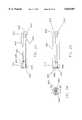
- FIG. 1is a side elevational view of a fully assembled installation tool, wherein the installation tool's shaft is in its first retracted position;
- FIG. 2is a side elevational view of the same fully assembled installation tool, wherein the installation tool's shaft is in its second extended position;
- FIG. 3is a side elevational view, in partial section, of the installation tool's shaft subassembly
- FIG. 4is a side elevational view of a sleeve which constitutes part of the installation tool
- FIG. 5is an end view showing the distal end of the sleeve
- FIG. 6is a side elevational view of a sleeve handle which constitutes part of the installation tool
- FIG. 7is an end view showing the proximal end of the sleeve handle
- FIG. 8is a side elevational view of a shaft which constitutes part of the installation tool's shaft subassembly;
- FIG. 9is an end view showing the proximal end of the shaft.
- FIG. 10is a side elevational view of a shaft housing which constitutes part of the installation tool's shaft subassembly;
- FIG. 11is a cross-sectional view taken along line 11--11 of FIG. 10;
- FIG. 12is an end view showing the proximal end of the shaft housing
- FIG. 13is a side view in section of a shaft handle which constitutes part of the installation tool's shaft subassembly;
- FIG. 14is an end view showing the proximal end of the shaft handle
- FIG. 15is a side view partially in section showing a bone anchor installed in the distal end of the bone anchor installation tool of the present invention.
- FIG. 16is a side view partially in section showing the bone anchor and bone anchor installation tool of FIG. 15, wherein the distal end of the installation tool is in engagement with the outer surface of a bone and the bone anchor is about to be deployed in that bone;
- FIG. 17is a view like that of FIG. 16, except that the bone anchor has been deployed in the bone;
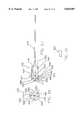
- FIG. 18is a side elevational view of an alternative embodiment of installation tool, wherein the installation tool shaft is in a retracted position;
- FIG. 19is similar to FIG. 18, but showing the installation tool shaft in an extended position
- FIG. 20is an interrupted side elevational view, in part broken away, and in part in section, of a sleeve portion of the tool of FIG. 18;
- FIG. 21is an interrupted side elevational view of a sleeve handle portion of the tool of FIG. 18 and the sleeve portion fixed thereto;
- FIG. 22is an end elevational view of the handle and sleeve portions of FIG. 21;
- FIG. 23is a side elevational view of the sleeve handle of FIG. 18;
- FIG. 24is an end elevational view of the sleeve handle of FIG. 23;
- FIG. 25is a sectional view taken along line 25--25 of FIG. 24;
- FIG. 26is an interrupted side elevational view, in part broken away and in part in section, of the installation tool of FIG. 18;
- FIG. 27is a centerline sectional view of a shaft handle portion of the tool of FIG. 18;
- FIG. 28is an end view of the shaft handle portion of FIG. 27;
- FIG. 29is an enlarged view of a portion of the shaft handle of FIG. 27;
- FIG. 30is a side elevational view of a shaft housing portion of the tool of FIG. 18;
- FIG. 31is an enlarged elevational view of a portion of the shaft housing of FIG. 30;
- FIG. 32is an end elevational view of the shaft housing of FIG. 30;
- FIG. 33is a sectional view taken along line 33--33 of FIG. 30;
- FIG. 34is a side elevational view of a shaft portion of the tool of FIG. 18;
- FIG. 35is a top plan view of the shaft of FIG. 34;
- FIG. 36is an end view of the shaft of FIG. 35;
- FIG. 37is a side elevational view of the shaft of FIG. 35.
- FIG. 38is a sectional view taken along line 38--38 of FIG. 37.
- Installation tool 5generally comprises a shaft subassembly 10 (FIGS. 1-3), a sleeve 15 (FIGS. 1, 2, 4 and 5) and a sleeve handle 20 (FIGS. 1, 2, 6 and 7).
- shaft subassembly 10generally comprises a shaft 25, a shaft housing 30, a shaft handle 35 and a rubber grommet 37.
- Shaft 25is shown in greater detail in FIGS. 8 and 9.
- Shaft 25comprises a first cylindrical portion 40 and a second cylindrical portion 45.
- Second cylindrical portion 45has a smaller diameter than first cylindrical portion 40.
- First cylindrical portion 40 and second cylindrical portion 45together define an annular shoulder 50.
- First cylindrical portion 40terminates in a distal end surface 55.
- Second cylindrical portion 45terminates in a proximal end surface 60.
- Shaft housing 30is shown in greater detail in FIGS. 10-12.
- Shaft housing 30comprises a fluted finger grip 65 having a flat distal surface 67.
- a stem 70extends distally away from the fluted finger grip's flat distal surface 67.
- Stem 70includes a threaded portion 75 and terminates in a chamfered distal nose 80.
- Shaft housing 30also comprises a cylindrical portion 85 extending proximally away from fluted finger grip 65. Cylindrical portion 85 includes an annular rib 90 and terminates in a flat proximal end surface 95.
- a central passageway 100extends through shaft housing 30, from chamfered distal nose 80 of stem 70 to flat proximal end surface 95 of cylindrical portion 85.
- Shaft handle 35is shown in greater detail in FIGS. 13 and 14.
- Shaft handle 35comprises a slotted cylindrical portion 105, a slotted flange 110 and a T-shaped post 115. More particularly, slotted cylindrical portion 105 comprises an inwardly facing lip 125 and four slots 130. Slots 130 are disposed in equally-circumferentially-spaced relation about the circumference of slotted cylindrical portion 105. In essence, slots 130 divide slotted cylindrical portion 105 into four longitudinally-extending fingers. Slotted flange 110 comprises four slots 135. Slots 135 are disposed in equally-circumferentially-spaced relation about the circumference of slotted flange 110. Slots 135 of slotted flange 110 are aligned with slots 130 of slotted cylindrical portion 105.
- Slotted flange 110terminates in a flat distal surface 137 and in a proximal surface 140.
- the flange's proximal surface 140is preferably rounded somewhat at its circumferential edge 142, adjacent to where proximal surface 140 meets flat distal surface 137.
- T-shaped post 115comprises a cylindrical central column 145 and an annular flange 150.
- Flange 150terminates in a rounded proximal surface 155 and in a flat distal surface 160.
- a rounded circumferential edge 165is defined by the intersection of rounded proximal surface 155 and flat distal surface 160.
- a hole 170extends axially through slotted flange 110 and into T-shaped post 115, and communicates with the interior of slotted cylindrical portion 105. Hole 170 is coaxial with, and communicates with, another hole 171 which opens on rounded proximal surface 155.
- Rubber grommet 37(FIGS. 1-3) comprises a toroidal shaped piece of elastomer adapted to be positioned on shaft handle 35. More particularly, rubber grommet 37 is adapted to be fit over the shaft handle's cylindrical central column 145 so as to be compressed between flat proximal surface 140 of slotted flange 110 and flat distal surface 160 of annular flange 150.
- Shaft subassembly 10is assembled as follows. First, the shaft's second portion 45 is passed through the shaft housing's central passageway 100 until the shaft housing's chamfered distal nose 80 engages the shaft's annular shoulder 50. Then shaft handle 35 is passed over the proximal end of shaft housing 30 until the proximal end of shaft 25 enters the shaft handle's hole 170. The proximal end of shaft 25 is then made fast in hole 170 by welding, using access hole 171. On account of the foregoing construction, shaft 25 and shaft handle 35 thereafter operate as a single unit, with shaft housing 30 being slidably captured on shaft 25 between the shaft's annular shoulder 50 and the shaft handle's distal surface 137, as will hereinafter be described in further detail. Once this has been accomplished, rubber grommet 37 is then mounted onto the shaft handle's cylindrical central column 145.
- sleeve 15comprises a distal portion 175 and a proximal portion 180.
- Distal portion 175comprises four slots 185.
- Slots 185are equally-circumferentially-spaced about the circumference of sleeve 15. Slots 185 open on the sleeve's distal end surface 190.
- the proximal portion of sleeve 15is flared outwardly at 195 and terminates in a proximal end surface 200.
- a central passageway 203extends between distal end surface 190 and proximal end surface 200.
- sleeve handle 20comprises a distal portion 205 and a proximal portion 210.
- Distal portion 205terminates in a rounded distal end surface 215 and proximal portion 210 terminates in a flat proximal end surface 220.
- Sleeve handle 20also includes a bore 225 and a counterbore 230. Bore 225 opens on the sleeve handle's rounded distal end surface 215 and counterbore 230 opens on the sleeve handle's flat proximal end surface 220. Bore 225 and counterbore 230 meet at an internal angled shoulder 235. The proximal portion of counterbore 230 is threaded at 240.
- a plurality of finger grip depressions 245are formed in the outer surface of sleeve handle 20.
- the complete bone anchor installation tool 5is assembled as follows. First, sleeve 15 is passed distal end first through counterbore 230 and bore 225 of sleeve handle 20, until the sleeve's flared portion 195 engages the sleeve handle's internal angled shoulder 235. Then the assembled shaft subassembly 10 is passed distal end first through counterbore 230 of sleeve handle 20 and central passageway 203 of sleeve 15, until chamfered distal nose 80 of shaft subassembly 10 enters counterbore 230 of sleeve handle 20.
- Shaft subassembly 10is then rotated so that the shaft housing's threaded portion 75 engages threads 240 of sleeve handle 20.
- Shaft subassembly 10is turned until the shaft housing's flat distal surface 67 engages the sleeve handle's proximal end surface 220.
- chamfered distal nose 80 of shaft subassembly 10will make a close fit with proximal end surface 200 of sleeve 15, so as to maintain the longitudinal position of sleeve 15 relative to the remainder of the installation tool.
- sleeve 15is free to rotate relative to the remainder of the installation tool.
- Bone anchor installation tool 5is preferably used to deploy a suture anchor of the sort disclosed in the aforementioned U.S. Pat. No. 5,217,486 and/or a suture anchor of the sort disclosed in the aforementioned U.S. patent application Ser. No. 08/197,927, i.e., bone anchor installation tool 5 is preferably used to deploy a suture anchor of the sort comprising (i) a generally cylindrical body, (ii) a pair of flexible barbs extending laterally out of the side of the body, and (iii) suture attachment means for attaching a length of suture to the body.
- bone anchor installation tool 5may also be used to deploy other types of bone anchors in bone or other types of fasteners in a workpiece, so long as such bone anchor or fastener is compatible with the present invention.
- Bone anchor installation tool 5is intended to be used as follows. First, installation tool 5 is positioned so that its shaft 25 is in its aforementioned first retracted position, wherein the shaft's annular shoulder 50 is substantially in engagement with the shaft housing's chamfered distal nose 80, and the shaft handle's inwardly facing lip 125 is on the proximal side of, and substantially in engagement with, the shaft housing's annular rib 90, and the shaft's distal end surface 55 is withdrawn into the interior of sleeve 15 (FIG. 1).
- bone anchor installation tool 5will be inclined to remain in its aforementioned first retracted position until it is thereafter forced to assume another position, inasmuch as the shaft housing's annular rib 90 will tend to inhibit passage of the shaft handle's inwardly facing lip 125.
- a suture anchor 300is loaded into the distal end of sleeve 15 so that the suture anchor's proximal end 305 rests against the shaft's distal end surface 55, with the suture anchor's two barbs 310 extending out through two of the sleeve's slots 185 and the suture anchor's two lengths of suture 315 extending out through the other two of the sleeve's slots 185.
- the two lengths of suture 315are then extended tautly back along the length of the installation tool and threaded through one or more of the shaft handle's slots 135 before being wound tightly around the shaft handle's cylindrical central column 145, in the space between rubber grommet 37 and the shaft handle's surface 140.
- the resilient engagement of rubber grommet 37 with the shaft's surface 140thereafter serves to keep the two lengths of suture 315 securely in place at the proximal end of the installation tool, yet allow a surgeon to easily pull the two lengths of suture free from the installation tool when needed.
- the two lengths of suture 315will serve to ensure that suture anchor 300 cannot become prematurely disengaged from the distal end of the installation tool.
- the installation toolis manipulated so as to position the distal portion of suture anchor 300 within the top of a hole 320 formed in a bone 325, with the distal end of sleeve 15 engaging the top surface 330 of the bone.
- Suture anchor 300can then be deployed in bone 325 by pressing on the shaft handle's proximal surface 155 so as to urge the installation tool's shaft 25 into its aforementioned second extended position. As this occurs, the shaft handle's inwardly facing lip 125 will be forced over the shaft housing's annular rib 90 as the shaft handle's flat distal end surface 137 moves into engagement with the shaft housing's flat proximal end surface 95 and the shaft's distal end surface 55 moves out of the sleeve's distal end.
- suture anchor 300will be driven out of the distal end of sleeve 15 and into bone 325, with the suture anchor's barbs 310 securing the anchor in place and with the two lengths of suture 315 extending back out of the bone hole to the installation tool.
- the two lengths of suture 315may then be unwound from the installation tool before the installation tool is removed from the surgical site.
- bone anchor installation tool 405which comprises a shaft subassembly 410, and a sleeve 415 fixed to, or integral with, a sleeve handle 420.
- shaft subassembly 410generally comprises a shaft 425, a shaft housing 430, a shaft handle 435 and a rubber grommet 437.
- Shaft housing 430is shown in greater detail in FIGS. 30-33.
- Shaft housing 430comprises a hexagonal nut finger grip 465 having a flat distal surface 467.
- a stem 470extends distally away from the finger grip's flat distal surface 467.
- Stem 470includes a threaded portion 475 and terminates in a chamfered distal nose 480.
- Shaft housing 430also comprises a cylindrical portion 485 extending proximally away from finger grip 465.
- Cylindrical portion 485includes an annular rib 490 and terminates in a flat proximal end surface 495.
- Cylindrical portion 485further includes elongated axially-extending recesses 497 which are aligned with slots 530 (FIGS. 18 and 19).
- a central passageway 500(FIGS. 30, 32, 33) extends through shaft housing 430, from chamfered distal nose 480 of stem 470 to flat proximal end surface 495 of cylindrical
- Shaft handle 435is shown in greater detail in FIGS. 26-29.
- Shaft handle 435comprises a slotted cylindrical portion 505, a slotted flange 510 and a headed post 515.
- slotted cylindrical portion 505comprises an inwardly facing lip 525 and two relatively wide slots 530.
- Slots 530are disposed in opposed relation about the circumference of slotted cylindrical portion 505. In essence, slots 530 divide slotted cylindrical portion 505 into two longitudinally-extending fingers.
- the wide slots 530preferably occupying at least 40% of the circumference of the cylindrical portion 505, facilitate easier cleaning of the tool 405 than is the case with cylindrical portion 105 of tool 5.
- Slotted flange 510comprises a plurality of slots 535 disposed in equally circumferentially spaced relation about the circumference of slotted flange 510. Slotted flange 510 terminates in a flat distal surface 537 and in a proximal surface 540.
- the flange's proximal surface 540is preferably rounded somewhat at its circumferential edge 542, adjacent to where proximal surface 540 meets flat distal surface 537.
- Headed post 515comprises a cylindrical central column 545 and an annular flange 550.
- Flange 550terminates in a rounded proximal surface 555 and in a flat distal surface 560.
- a rounded circumferential edge 565is defined by the intersection of rounded proximal surface 555 and flat distal surface 560.
- a hole 570(FIG. 27) extends axially through slotted flange 510 and into headed post 515, and communicates with the interior of slotted cylindrical portion 505. Hole 570 is coaxial with, and communicates with, another hole 571 which opens on rounded proximal surface 555.
- Rubber grommet 437(FIGS. 26 and 27) comprises a toroidal shaped piece of elastomer adapted to be positioned on shaft handle 435. More particularly, rubber grommet 437 is adapted to be fit over the shaft handle's cylindrical central column 545 so as to be compressed between flat proximal surface 540 of slotted flange 510 and flat distal surface 560 of annular flange 550.
- the shaft 425is passed through the shaft housing's central passageway 500.
- shaft handle 435with shaft 425 fixed thereto, is passed over the proximal end of shaft housing 430 with the shaft handle slots 530 aligned, respectively, with the shaft housing elongated recesses 497, and the shaft 425 extending through shaft housing 430.
- the shaft 425 and shaft handle 435fixed together, operate as a single unit, with shaft housing 430 being slidably disposed on shaft 425.
- Elastomer grommet 437is then mounted onto the shaft handle's cylindrical central column 545.
- sleeve 415comprises a distal portion 575 and a proximal portion 580.
- Distal portion 575comprises at least two slots 585. Slots 585 are equally circumferentially spaced about the circumference of sleeve 415. Slots 585 open on the sleeve's distal end surface 590.
- the sleeve distal portion 575is further provided with an internal annular shoulder 577 (FIG. 20), for receiving the proximal end 305 of suture anchor 300.
- the proximal portion 580 of sleeve 415is joined to, or integral with, sleeve handle 420.
- a central passageway 603extends between distal and proximal ends of sleeve 415.
- sleeve handle 420comprises a distal portion 605 and a proximal portion 610.
- Distal portion 605terminates in a rounded distal end surface 615 and proximal portion 610 terminates in a flat proximal end surface 620.
- Sleeve handle 420also includes a bore 625 and a counterbore 630.
- Bore 625opens on the sleeve handle's rounded distal end surface 615 and counterbore 630 opens on the sleeve handle's flat proximal end surface 620.
- Bore 625 and counterbore 630meet at an internal angled shoulder 635.
- the proximal portion of counterbore 630is threaded at 640.
- a plurality of finger grip depressions 645are formed in the outer surface of sleeve handle 420.
- the complete bone anchor installation tool 405is assembled as follows.
- the assembled shaft subassembly 410is passed distal end first through counterbore 630 of sleeve handle 420 and central passageway 603 of sleeve 415, until chamfered distal nose 480 of shaft subassembly 410 enters counterbore 630 of sleeve handle 420.
- Shaft subassembly 410is then rotated so that the shaft housing's threaded portion 475 engages threads 640 of sleeve handle 420.
- Shaft subassembly 410is turned until the shaft housing's flat distal surface 467 engages the sleeve handle's proximal end surface 620.
- Bone anchor installation tool 405preferably is used to deploy a suture anchor of the sort disclosed in the aforementioned U.S. Pat. No. 5,217,486 and/or a suture anchor of the sort disclosed in the aforementioned U.S. patent application Ser. No. 08/197,927, i.e., bone anchor installation tool 405 preferably is used to deploy a suture anchor of the sort comprising (i) a generally cylindrical body, (ii) a pair of flexible barbs extending laterally out of the side of the body, and (iii) suture attachment means for attaching a length of suture to the body.
- bone anchor installation tool 405may also be used to deploy other types of bone anchors in bone or other types of fasteners in a workpiece, so long as such bone anchor or fastener is compatible with the present invention.
- Bone anchor installation tool 405is intended to be used as follows. First, installation tool 405 is positioned so that its shaft 425 is in its aforementioned first retracted position, wherein the shaft handle's inwardly facing lip 525 is on the proximal side of, and substantially in engagement with, the shaft housing's annular rib 490, and the shaft's distal end is withdrawn into the interior of sleeve 415 (FIG. 18). It is to be appreciated that bone anchor installation tool 405 will be inclined to remain in its aforementioned first retracted position until it is thereafter forced to assume another position, inasmuch as the shaft housing's annular rib 490 will tend to inhibit passage of the shaft handle's inwardly facing lip 525.
- suture anchor 300is loaded into the distal end of sleeve 415 so that the suture anchor's proximal end rests against the sleeve shoulder 577, with the suture anchor's two barbs 310 and two lengths of suture 315 extending out through the sleeve's slots 585.
- the two lengths of suture 315are then extended tautly back along the length of the installation tool and threaded through one or more of the shaft handle's slots 535 before being wound tightly around the shaft handle's cylindrical central column 545, in the space between rubber grommet 437 and the shaft handle's surface 540.
- the resilient engagement of rubber grommet 437 with the shaft's surface 540thereafter serves to keep the two lengths of suture 315 securely in place at the proximal end of the installation tool, yet allow a surgeon to easily pull the two lengths of suture free from the installation tool when needed.
- the two lengths of suture 315will serve to ensure that suture anchor 300 cannot become prematurely disengaged from the distal end of the installation tool.
- the installation tool 405is manipulated so as to position the distal portion of suture anchor 300 within the top of the hole 320 formed in the bone 325, with the distal end of sleeve 415 engaging the top surface 330 of the bone, as depicted in FIG. 16 with respect to installation tool 5.
- Suture anchor 300can then be deployed in bone 325 by pressing on the shaft handle's proximal surface 555 so as to urge the installation tool's shaft 425 into its aforementioned second extended position. As this occurs, the shaft handle's inwardly facing lip 525 is forced over the shaft housing's annular rib 490 as the shaft handle's flat distal end surface 537 moves into engagement with the shaft housing's flat proximal end surface 495 and the shaft's distal end moves out of the sleeve's distal end.
- suture anchor 300is driven out of the distal end of sleeve 415 and into bone 325, with the suture anchor's barbs 310 securing the anchor in place and with the two lengths of suture 315 extending back out of the bone hole to the installation tool.
- the two lengths of suture 315may then be unwound from the installation tool before the installation tool is removed from the surgical site.
- shaft housing 430is provided with a cross-pin 498, or similar inwardly-directed protrusion, which extends slightly into central passageway 500.
- shaft 425is provided with a notch 426 which receives the protrusion 498.
- the shaft handle 435is mounted on the shaft housing 430 such that the shaft handle slots 530 are in alignment with the shaft housing elongated recesses 497.
- the protrusion 498is received by a slide surface 427 on shaft 425.
- shaft handle 435is pushed distally, to cause shaft handle lip 525 to override rib 490, protrusion 498 engages a shoulder 428 to stop axial movement of shaft 425, with the distal end of shaft 425 still within sleeve 415.
- the shaft handle 435is then rotated 180° to bring slide wall 429 into alignment with protrusion 498, allowing shaft 425 to move distally so as to extend the distal end of shaft 425 out of the distal end 590 of sleeve 415.
- shaft handle 435is prevented from rotating on shaft housing 430.
- shaft handle 435will not rotate, but remains stationery to facilitate the winding of suture 315 thereon.
- shaft handle 435is urged in a clockwise turning direction while being moved distally along shaft housing 430.
- notch 426receives protrusion 498 and permits turning of shaft handle 435 on shaft housing 430 180°, and withdrawal of shaft handle 435 and shaft 425 from shaft housing 430.
- Shaft housing 430may then be unscrewed from sleeve handle 420.
- the shaft housing protrusion 498cooperates with the notch and slide surfaces 426, 427, and 429 of the shaft 425 to determine axial and rotative mobility of the shaft handle 435 on the shaft housing 430. Such cooperation prevents unwanted movement but permits beneficial movement.
- the above described alternative embodimentprovides advantages over the above first-described embodiment.
- suture 315may be more easily wound between grommet 437 and surface 540.
- the alternative embodimentis easier to clean because of (1) the wide slots 530 in the shaft handle 435 and (2) the separability of the tool into three sections: (1) the shaft handle 435 and shaft 425, (2) the shaft housing 430, and (3) the sleeve handle 420 and sleeve 415.
- an improved bone anchor installation toolis provided.
- an improved bone anchor installation toolis provided, wherein the installation tool is adapted to deploy bone anchors of the type adapted to anchor suture to bone.
- an improved bone anchor installation toolis provided, wherein the installation tool is adapted to provide improved suture management means for managing the free end or ends of a suture or sutures attached to the bone anchor.
- an improved bone anchor installation toolis provided, wherein the installation tool is relatively easy to manufacture and relatively inexpensive to produce.
- an improved methodis provided for deploying a bone anchor in bone.
- the number of slots provided in the distal end of sleeve 415may be varied.
- the number of slots provided in slotted cylindrical portion 105, 505 and/or the number of slots provided in slotted flange 110, 510may be varied.
- finger grip 65can be formed with an exterior surface which is knurled rather than fluted or hexagonal, or finger grip 65 can be formed with a relatively smooth surface, if desired.
- suture 315can be held to the proximal end of the installation tool by wrapping it around cylindrical central column 145, 545 between rubber grommet 37, 437 and the shaft handle's flat surface 160, 560 rather than between rubber grommet 37, 437 and the shaft handle's surface 140, 540.
Landscapes
- Health & Medical Sciences (AREA)
- Surgery (AREA)
- Life Sciences & Earth Sciences (AREA)
- Biomedical Technology (AREA)
- Nuclear Medicine, Radiotherapy & Molecular Imaging (AREA)
- Engineering & Computer Science (AREA)
- Rheumatology (AREA)
- Heart & Thoracic Surgery (AREA)
- Medical Informatics (AREA)
- Molecular Biology (AREA)
- Animal Behavior & Ethology (AREA)
- General Health & Medical Sciences (AREA)
- Public Health (AREA)
- Veterinary Medicine (AREA)
- Surgical Instruments (AREA)
Abstract
Description
Claims (8)
Priority Applications (3)
| Application Number | Priority Date | Filing Date | Title |
|---|---|---|---|
| US08/791,000US5843087A (en) | 1997-01-30 | 1997-01-30 | Suture anchor installation tool |
| PCT/US1998/001713WO1998033440A1 (en) | 1997-01-30 | 1998-01-29 | Suture anchor installation tool |
| AU62551/98AAU6255198A (en) | 1997-01-30 | 1998-01-29 | Suture anchor installation tool |
Applications Claiming Priority (1)
| Application Number | Priority Date | Filing Date | Title |
|---|---|---|---|
| US08/791,000US5843087A (en) | 1997-01-30 | 1997-01-30 | Suture anchor installation tool |
Publications (1)
| Publication Number | Publication Date |
|---|---|
| US5843087Atrue US5843087A (en) | 1998-12-01 |
Family
ID=25152364
Family Applications (1)
| Application Number | Title | Priority Date | Filing Date |
|---|---|---|---|
| US08/791,000Expired - LifetimeUS5843087A (en) | 1997-01-30 | 1997-01-30 | Suture anchor installation tool |
Country Status (3)
| Country | Link |
|---|---|
| US (1) | US5843087A (en) |
| AU (1) | AU6255198A (en) |
| WO (1) | WO1998033440A1 (en) |
Cited By (78)
| Publication number | Priority date | Publication date | Assignee | Title |
|---|---|---|---|---|
| US5954747A (en)* | 1997-11-20 | 1999-09-21 | Clark; Ron | Meniscus repair anchor system |
| US6557426B2 (en) | 2000-02-01 | 2003-05-06 | Richard L. Reinemann, Jr. | Method and apparatus for testing suture anchors |
| US20030204193A1 (en)* | 2002-04-25 | 2003-10-30 | Stefan Gabriel | Suture anchor insertion tool |
| US6656183B2 (en) | 2001-11-08 | 2003-12-02 | Smith & Nephew, Inc. | Tissue repair system |
| US6692516B2 (en)* | 2000-11-28 | 2004-02-17 | Linvatec Corporation | Knotless suture anchor and method for knotlessly securing tissue |
| US20060106422A1 (en)* | 2004-11-16 | 2006-05-18 | Del Rio Eddy W | Anchor/suture used for medical procedures |
| US7651509B2 (en) | 1999-12-02 | 2010-01-26 | Smith & Nephew, Inc. | Methods and devices for tissue repair |
| US7867251B2 (en) | 2001-11-08 | 2011-01-11 | Smith & Nephew, Inc. | Reattachment of tissue to base tissue |
| US20110106154A1 (en)* | 2009-10-30 | 2011-05-05 | DePuy Mikek, Inc. | Partial thickness rotator cuff repair system and method |
| US20110106013A1 (en)* | 2009-10-30 | 2011-05-05 | DePuy Mikek, Inc. | Dual cannula system and method for partial thickness rotator cuff repair |
| US7996967B2 (en) | 2001-08-31 | 2011-08-16 | Quill Medical, Inc. | System for variable-angle cutting of a suture to create tissue retainers of a desired shape and size |
| US8032996B2 (en) | 2003-05-13 | 2011-10-11 | Quill Medical, Inc. | Apparatus for forming barbs on a suture |
| US8083770B2 (en) | 2002-08-09 | 2011-12-27 | Quill Medical, Inc. | Suture anchor and method |
| US8118834B1 (en) | 2007-12-20 | 2012-02-21 | Angiotech Pharmaceuticals, Inc. | Composite self-retaining sutures and method |
| US8216273B1 (en) | 2008-02-25 | 2012-07-10 | Ethicon, Inc. | Self-retainers with supporting structures on a suture |
| US8246652B2 (en) | 1993-05-03 | 2012-08-21 | Ethicon, Inc. | Suture with a pointed end and an anchor end and with equally spaced yieldable tissue grasping barbs located at successive axial locations |
| US8323315B2 (en) | 1998-12-30 | 2012-12-04 | Depuy Mitek, Inc. | Suture locking device |
| US8512375B2 (en) | 1999-12-02 | 2013-08-20 | Smith & Nephew, Inc. | Closure device and method for tissue repair |
| US8545535B2 (en) | 2009-05-12 | 2013-10-01 | Foundry Newco Xi, Inc. | Suture anchors with one-way cinching mechanisms |
| US8615856B1 (en) | 2008-01-30 | 2013-12-31 | Ethicon, Inc. | Apparatus and method for forming self-retaining sutures |
| US8623051B2 (en) | 2005-06-24 | 2014-01-07 | Smith & Nephew, Inc. | Tissue repair device |
| US8641732B1 (en) | 2008-02-26 | 2014-02-04 | Ethicon, Inc. | Self-retaining suture with variable dimension filament and method |
| US8721681B2 (en) | 2002-09-30 | 2014-05-13 | Ethicon, Inc. | Barbed suture in combination with surgical needle |
| US8721664B2 (en) | 2004-05-14 | 2014-05-13 | Ethicon, Inc. | Suture methods and devices |
| US8734485B2 (en) | 2002-09-30 | 2014-05-27 | Ethicon, Inc. | Sutures with barbs that overlap and cover projections |
| US8747437B2 (en) | 2001-06-29 | 2014-06-10 | Ethicon, Inc. | Continuous stitch wound closure utilizing one-way suture |
| US8771313B2 (en) | 2007-12-19 | 2014-07-08 | Ethicon, Inc. | Self-retaining sutures with heat-contact mediated retainers |
| US8777987B2 (en) | 2007-09-27 | 2014-07-15 | Ethicon, Inc. | Self-retaining sutures including tissue retainers having improved strength |
| US8793863B2 (en) | 2007-04-13 | 2014-08-05 | Ethicon, Inc. | Method and apparatus for forming retainers on a suture |
| US8801755B2 (en) | 2004-04-06 | 2014-08-12 | Arthrex, Inc. | Suture anchor |
| US8821541B2 (en) | 1999-02-02 | 2014-09-02 | Arthrex, Inc. | Suture anchor with insert-molded rigid member |
| US8875607B2 (en) | 2008-01-30 | 2014-11-04 | Ethicon, Inc. | Apparatus and method for forming self-retaining sutures |
| US8876865B2 (en) | 2008-04-15 | 2014-11-04 | Ethicon, Inc. | Self-retaining sutures with bi-directional retainers or uni-directional retainers |
| US8916077B1 (en) | 2007-12-19 | 2014-12-23 | Ethicon, Inc. | Self-retaining sutures with retainers formed from molten material |
| US8932328B2 (en) | 2008-11-03 | 2015-01-13 | Ethicon, Inc. | Length of self-retaining suture and method and device for using the same |
| US8951268B2 (en)* | 2010-05-17 | 2015-02-10 | I.B.I. Israel Biomedical Innovations Ltd. | Surgical fastening device with mesh retaining means |
| US8961560B2 (en) | 2008-05-16 | 2015-02-24 | Ethicon, Inc. | Bidirectional self-retaining sutures with laser-marked and/or non-laser marked indicia and methods |
| USRE45426E1 (en) | 1997-05-21 | 2015-03-17 | Ethicon, Inc. | Surgical methods using one-way suture |
| US9125647B2 (en) | 2008-02-21 | 2015-09-08 | Ethicon, Inc. | Method and apparatus for elevating retainers on self-retaining sutures |
| US9179907B2 (en) | 2000-06-22 | 2015-11-10 | Arthrex, Inc. | Knotless graft fixation assembly |
| US9248580B2 (en) | 2002-09-30 | 2016-02-02 | Ethicon, Inc. | Barb configurations for barbed sutures |
| US9314237B2 (en) | 2008-05-20 | 2016-04-19 | DePuy Synthes Products, Inc. | Knotless suture anchor and receptacle combination |
| US9314235B2 (en) | 2003-02-05 | 2016-04-19 | Smith & Nephew, Inc. | Tissue anchor and insertion tool |
| US9351728B2 (en) | 2013-06-28 | 2016-05-31 | Covidien Lp | Articulating apparatus for endoscopic procedures |
| US9351733B2 (en) | 2013-01-18 | 2016-05-31 | Covidien Lp | Surgical fastener applier |
| US9358004B2 (en) | 2013-06-28 | 2016-06-07 | Covidien Lp | Articulating apparatus for endoscopic procedures |
| US9358010B2 (en) | 2013-03-12 | 2016-06-07 | Covidien Lp | Flex cable and spring-loaded tube for tacking device |
| US9364274B2 (en) | 2003-06-13 | 2016-06-14 | Covidien Lp | Multiple member interconnect for surgical instrument and absorbable screw fastener |
| US9463010B2 (en) | 2009-05-12 | 2016-10-11 | The Foundry, Llc | Methods and devices to treat diseased or injured musculoskeletal tissue |
| US9521999B2 (en) | 2005-09-13 | 2016-12-20 | Arthrex, Inc. | Fully-threaded bioabsorbable suture anchor |
| US9526498B2 (en) | 2013-09-17 | 2016-12-27 | Covidien Lp | Surgical device with a trigger lockout mechanism device |
| US9538999B2 (en) | 2013-03-13 | 2017-01-10 | Medos International Sàrl | Suture storage devices, systems, and methods |
| US9655621B2 (en) | 2013-03-15 | 2017-05-23 | Covidien Lp | Surgical instrument for dispensing tacks and solution |
| US9668730B2 (en) | 2013-06-28 | 2017-06-06 | Covidien Lp | Articulating apparatus for endoscopic procedures with timing system |
| US9675341B2 (en) | 2010-11-09 | 2017-06-13 | Ethicon Inc. | Emergency self-retaining sutures and packaging |
| US9867620B2 (en) | 2013-03-14 | 2018-01-16 | Covidien Lp | Articulation joint for apparatus for endoscopic procedures |
| US9955962B2 (en) | 2010-06-11 | 2018-05-01 | Ethicon, Inc. | Suture delivery tools for endoscopic and robot-assisted surgery and methods |
| US10085746B2 (en) | 2013-06-28 | 2018-10-02 | Covidien Lp | Surgical instrument including rotating end effector and rotation-limiting structure |
| US10098634B2 (en) | 2004-04-27 | 2018-10-16 | Covidien Lp | Absorbable fastener for hernia mesh fixation |
| US10188384B2 (en) | 2011-06-06 | 2019-01-29 | Ethicon, Inc. | Methods and devices for soft palate tissue elevation procedures |
| US10335146B2 (en) | 2014-04-02 | 2019-07-02 | Coviden Lp | Surgical fastener applying apparatus, kits and methods for endoscopic procedures |
| US10383624B2 (en) | 2008-10-24 | 2019-08-20 | The Foundry, Llc | Methods and devices for suture anchor delivery |
| US10420546B2 (en) | 2010-05-04 | 2019-09-24 | Ethicon, Inc. | Self-retaining systems having laser-cut retainers |
| US10492780B2 (en) | 2011-03-23 | 2019-12-03 | Ethicon, Inc. | Self-retaining variable loop sutures |
| US10617409B2 (en) | 2016-10-21 | 2020-04-14 | Covidien Lp | Surgical end effectors |
| US10653507B2 (en) | 2013-07-24 | 2020-05-19 | Covidien Lp | Expanding absorbable tack |
| US10743859B2 (en) | 2016-10-21 | 2020-08-18 | Covidien Lp | Surgical end effectors |
| US10888309B2 (en) | 2017-01-31 | 2021-01-12 | Covidien Lp | Surgical fastener devices with geometric tubes |
| US11007296B2 (en) | 2010-11-03 | 2021-05-18 | Ethicon, Inc. | Drug-eluting self-retaining sutures and methods relating thereto |
| US11090097B2 (en) | 2015-03-17 | 2021-08-17 | Covidien Lp | Connecting end effectors to surgical devices |
| US11116500B2 (en) | 2018-06-28 | 2021-09-14 | Covidien Lp | Surgical fastener applying device, kits and methods for endoscopic procedures |
| US11197675B2 (en) | 2019-12-19 | 2021-12-14 | Covidien Lp | Positioning guide for surgical instruments and surgical instrument systems |
| USD944984S1 (en) | 2019-12-19 | 2022-03-01 | Covidien Lp | Tubular positioning guide |
| USD944985S1 (en) | 2019-12-19 | 2022-03-01 | Covidien Lp | Positioning guide cuff |
| US11298126B2 (en) | 2018-05-02 | 2022-04-12 | Covidien Lp | Shipping wedge for end effector installation onto surgical devices |
| US11298123B2 (en) | 2016-10-21 | 2022-04-12 | Covidien Lp | Surgical end effectors |
| US20220287702A1 (en)* | 2019-08-26 | 2022-09-15 | Janssen Biotech, Inc. | Tissue anchor and related methods |
| US11523817B2 (en) | 2019-06-27 | 2022-12-13 | Covidien Lp | Endoluminal pursestring device |
Citations (3)
| Publication number | Priority date | Publication date | Assignee | Title |
|---|---|---|---|---|
| US4898156A (en)* | 1987-05-18 | 1990-02-06 | Mitek Surgical Products, Inc. | Suture anchor |
| US5002550A (en)* | 1989-06-06 | 1991-03-26 | Mitek Surgical Products, Inc. | Suture anchor installation tool |
| US5520696A (en)* | 1994-09-27 | 1996-05-28 | Mitek Surgical Products, Inc. | Bone anchor installation tool |
Family Cites Families (2)
| Publication number | Priority date | Publication date | Assignee | Title |
|---|---|---|---|---|
| US5690677A (en)* | 1994-02-17 | 1997-11-25 | Arthrex, Inc. | Method for installing a suture anchor through a cannulated tissue-shifting guide |
| US5720751A (en)* | 1996-11-27 | 1998-02-24 | Jackson; Roger P. | Tools for use in seating spinal rods in open ended implants |
- 1997
- 1997-01-30USUS08/791,000patent/US5843087A/ennot_activeExpired - Lifetime
- 1998
- 1998-01-29AUAU62551/98Apatent/AU6255198A/ennot_activeAbandoned
- 1998-01-29WOPCT/US1998/001713patent/WO1998033440A1/enactiveApplication Filing
Patent Citations (4)
| Publication number | Priority date | Publication date | Assignee | Title |
|---|---|---|---|---|
| US4898156A (en)* | 1987-05-18 | 1990-02-06 | Mitek Surgical Products, Inc. | Suture anchor |
| US5192303A (en)* | 1987-05-18 | 1993-03-09 | Mitek Surgical Products, Inc. | Suture anchor |
| US5002550A (en)* | 1989-06-06 | 1991-03-26 | Mitek Surgical Products, Inc. | Suture anchor installation tool |
| US5520696A (en)* | 1994-09-27 | 1996-05-28 | Mitek Surgical Products, Inc. | Bone anchor installation tool |
Cited By (161)
| Publication number | Priority date | Publication date | Assignee | Title |
|---|---|---|---|---|
| US8246652B2 (en) | 1993-05-03 | 2012-08-21 | Ethicon, Inc. | Suture with a pointed end and an anchor end and with equally spaced yieldable tissue grasping barbs located at successive axial locations |
| USRE45426E1 (en) | 1997-05-21 | 2015-03-17 | Ethicon, Inc. | Surgical methods using one-way suture |
| US6306156B1 (en) | 1997-11-20 | 2001-10-23 | Ron Clark | Meniscus repair anchor system |
| US5954747A (en)* | 1997-11-20 | 1999-09-21 | Clark; Ron | Meniscus repair anchor system |
| US8323315B2 (en) | 1998-12-30 | 2012-12-04 | Depuy Mitek, Inc. | Suture locking device |
| US8512374B2 (en) | 1998-12-30 | 2013-08-20 | Depuy Mitek, Llc | Soft tissue locking device |
| US9526493B2 (en) | 1999-02-02 | 2016-12-27 | Arthrex, Inc. | Suture anchor with insert-molded rigid member |
| US8821541B2 (en) | 1999-02-02 | 2014-09-02 | Arthrex, Inc. | Suture anchor with insert-molded rigid member |
| US9549726B2 (en) | 1999-02-02 | 2017-01-24 | Arthrex, Inc. | Suture anchor with insert-molded rigid member |
| US9220494B2 (en) | 1999-12-02 | 2015-12-29 | Smith & Nephew, Inc. | Methods for tissue repair |
| US8366744B2 (en) | 1999-12-02 | 2013-02-05 | Smith & Nephew, Inc. | Apparatus for tissue repair |
| US7651509B2 (en) | 1999-12-02 | 2010-01-26 | Smith & Nephew, Inc. | Methods and devices for tissue repair |
| US9492160B2 (en) | 1999-12-02 | 2016-11-15 | Smith & Nephew, Inc. | Closure device and method for tissue repair |
| US8512375B2 (en) | 1999-12-02 | 2013-08-20 | Smith & Nephew, Inc. | Closure device and method for tissue repair |
| US9545251B2 (en) | 1999-12-02 | 2017-01-17 | Smith & Nephew, Inc. | Apparatus for tissue repair |
| US7887551B2 (en) | 1999-12-02 | 2011-02-15 | Smith & Nephew, Inc. | Soft tissue attachment and repair |
| US9295461B2 (en) | 1999-12-02 | 2016-03-29 | Smith & Nephew, Inc. | Methods for tissue repair |
| US9833231B2 (en) | 1999-12-02 | 2017-12-05 | Smith & Nephew, Inc. | Apparatus for tissue repair |
| US6557426B2 (en) | 2000-02-01 | 2003-05-06 | Richard L. Reinemann, Jr. | Method and apparatus for testing suture anchors |
| US9775599B2 (en) | 2000-06-22 | 2017-10-03 | Arthrex, Inc. | Knotless tissue fixation assembly |
| US9179907B2 (en) | 2000-06-22 | 2015-11-10 | Arthrex, Inc. | Knotless graft fixation assembly |
| US10709436B2 (en) | 2000-06-22 | 2020-07-14 | Arthrex, Inc. | Graft fixation using a plug against suture |
| US10716556B2 (en) | 2000-06-22 | 2020-07-21 | Arthtrex, Inc. | Knotless tissue fixation assembly |
| US10052091B2 (en) | 2000-06-22 | 2018-08-21 | Arthrex, Inc. | Knotless suture or tissue fixation using an implant having a pointed tip |
| US9706986B2 (en) | 2000-06-22 | 2017-07-18 | Arthrex, Inc. | Knotless suture and tissue securing method |
| US20100100129A1 (en)* | 2000-11-28 | 2010-04-22 | Linvatec Corporation | Knotless suture anchor and method for knotlessly securing tissues |
| US20100100126A1 (en)* | 2000-11-28 | 2010-04-22 | Linvatec Corporation | Knotless suture anchor and method for knotlessly securing tissues |
| US8029537B2 (en) | 2000-11-28 | 2011-10-04 | Linvatec Corporation | Knotless suture anchor and method for knotlessly securing tissues |
| US6692516B2 (en)* | 2000-11-28 | 2004-02-17 | Linvatec Corporation | Knotless suture anchor and method for knotlessly securing tissue |
| US8764796B2 (en) | 2001-06-29 | 2014-07-01 | Ethicon, Inc. | Suture method |
| US8764776B2 (en) | 2001-06-29 | 2014-07-01 | Ethicon, Inc. | Anastomosis method using self-retaining sutures |
| US8777989B2 (en) | 2001-06-29 | 2014-07-15 | Ethicon, Inc. | Subcutaneous sinusoidal wound closure utilizing one-way suture |
| US8777988B2 (en) | 2001-06-29 | 2014-07-15 | Ethicon, Inc. | Methods for using self-retaining sutures in endoscopic procedures |
| US8747437B2 (en) | 2001-06-29 | 2014-06-10 | Ethicon, Inc. | Continuous stitch wound closure utilizing one-way suture |
| US8011072B2 (en) | 2001-08-31 | 2011-09-06 | Quill Medical, Inc. | Method for variable-angle cutting of a suture to create tissue retainers of a desired shape and size |
| US8926659B2 (en) | 2001-08-31 | 2015-01-06 | Ethicon, Inc. | Barbed suture created having barbs defined by variable-angle cut |
| US7996967B2 (en) | 2001-08-31 | 2011-08-16 | Quill Medical, Inc. | System for variable-angle cutting of a suture to create tissue retainers of a desired shape and size |
| US8028387B2 (en) | 2001-08-31 | 2011-10-04 | Quill Medical, Inc. | System for supporting and cutting suture thread to create tissue retainers thereon |
| US8028388B2 (en) | 2001-08-31 | 2011-10-04 | Quill Medical, Inc. | System for cutting a suture to create tissue retainers of a desired shape and size |
| US8020263B2 (en) | 2001-08-31 | 2011-09-20 | Quill Medical, Inc. | Automated system for cutting tissue retainers on a suture |
| US7996968B2 (en) | 2001-08-31 | 2011-08-16 | Quill Medical, Inc. | Automated method for cutting tissue retainers on a suture |
| US8015678B2 (en) | 2001-08-31 | 2011-09-13 | Quill Medical, Inc. | Method for cutting a suture to create tissue retainers of a desired shape and size |
| US9060762B2 (en) | 2001-11-08 | 2015-06-23 | Smith & Nephew, Inc. | Reattachment of tissue to base tissue |
| US6656183B2 (en) | 2001-11-08 | 2003-12-02 | Smith & Nephew, Inc. | Tissue repair system |
| US6986781B2 (en) | 2001-11-08 | 2006-01-17 | Smith & Nephew, Inc. | Tissue repair system |
| US7867251B2 (en) | 2001-11-08 | 2011-01-11 | Smith & Nephew, Inc. | Reattachment of tissue to base tissue |
| US7309337B2 (en) | 2001-11-08 | 2007-12-18 | Smith & Nephew, Inc. | Tissue repair system |
| US20030204193A1 (en)* | 2002-04-25 | 2003-10-30 | Stefan Gabriel | Suture anchor insertion tool |
| US8734486B2 (en) | 2002-08-09 | 2014-05-27 | Ethicon, Inc. | Multiple suture thread configuration with an intermediate connector |
| US8083770B2 (en) | 2002-08-09 | 2011-12-27 | Quill Medical, Inc. | Suture anchor and method |
| US8652170B2 (en) | 2002-08-09 | 2014-02-18 | Ethicon, Inc. | Double ended barbed suture with an intermediate body |
| US8679158B2 (en) | 2002-08-09 | 2014-03-25 | Ethicon, Inc. | Multiple suture thread configuration with an intermediate connector |
| US8690914B2 (en) | 2002-08-09 | 2014-04-08 | Ethicon, Inc. | Suture with an intermediate barbed body |
| US8852232B2 (en) | 2002-09-30 | 2014-10-07 | Ethicon, Inc. | Self-retaining sutures having effective holding strength and tensile strength |
| US8734485B2 (en) | 2002-09-30 | 2014-05-27 | Ethicon, Inc. | Sutures with barbs that overlap and cover projections |
| US8721681B2 (en) | 2002-09-30 | 2014-05-13 | Ethicon, Inc. | Barbed suture in combination with surgical needle |
| US9248580B2 (en) | 2002-09-30 | 2016-02-02 | Ethicon, Inc. | Barb configurations for barbed sutures |
| US8795332B2 (en) | 2002-09-30 | 2014-08-05 | Ethicon, Inc. | Barbed sutures |
| US8821540B2 (en) | 2002-09-30 | 2014-09-02 | Ethicon, Inc. | Self-retaining sutures having effective holding strength and tensile strength |
| US9314235B2 (en) | 2003-02-05 | 2016-04-19 | Smith & Nephew, Inc. | Tissue anchor and insertion tool |
| US8032996B2 (en) | 2003-05-13 | 2011-10-11 | Quill Medical, Inc. | Apparatus for forming barbs on a suture |
| US9364274B2 (en) | 2003-06-13 | 2016-06-14 | Covidien Lp | Multiple member interconnect for surgical instrument and absorbable screw fastener |
| US9662106B2 (en) | 2003-06-13 | 2017-05-30 | Covidien Lp | Surgical fastener with predetermined resorption rate |
| US9622739B2 (en) | 2004-04-06 | 2017-04-18 | Arthrex, Inc. | Suture anchor |
| US10537319B2 (en) | 2004-04-06 | 2020-01-21 | Arthrex, Inc. | Suture anchor |
| US8801755B2 (en) | 2004-04-06 | 2014-08-12 | Arthrex, Inc. | Suture anchor |
| US10098634B2 (en) | 2004-04-27 | 2018-10-16 | Covidien Lp | Absorbable fastener for hernia mesh fixation |
| US11723654B2 (en) | 2004-05-14 | 2023-08-15 | Ethicon, Inc. | Suture methods and devices |
| US10548592B2 (en) | 2004-05-14 | 2020-02-04 | Ethicon, Inc. | Suture methods and devices |
| US10779815B2 (en) | 2004-05-14 | 2020-09-22 | Ethicon, Inc. | Suture methods and devices |
| US8721664B2 (en) | 2004-05-14 | 2014-05-13 | Ethicon, Inc. | Suture methods and devices |
| US8696703B2 (en) | 2004-11-16 | 2014-04-15 | DePuy Synthes Products, LLC | Anchor/suture used for medical procedures |
| US20070032793A1 (en)* | 2004-11-16 | 2007-02-08 | Del Rio Eddy W | Anchor/suture used for medical procedures |
| US7144415B2 (en) | 2004-11-16 | 2006-12-05 | The Anspach Effort, Inc. | Anchor/suture used for medical procedures |
| US20060106422A1 (en)* | 2004-11-16 | 2006-05-18 | Del Rio Eddy W | Anchor/suture used for medical procedures |
| US9566058B2 (en) | 2004-11-16 | 2017-02-14 | DePuy Synthes Products, Inc. | Anchor/suture used for medical procedures |
| US8623051B2 (en) | 2005-06-24 | 2014-01-07 | Smith & Nephew, Inc. | Tissue repair device |
| US9173653B2 (en) | 2005-06-24 | 2015-11-03 | Smith & Nephew, Inc. | Tissue repair device |
| US12064104B2 (en) | 2005-09-13 | 2024-08-20 | Arthrex, Inc. | Fully-threaded bioabsorbable suture anchor |
| US11324493B2 (en) | 2005-09-13 | 2022-05-10 | Arthrex, Inc. | Fully-threaded bioabsorbable suture anchor |
| US9521999B2 (en) | 2005-09-13 | 2016-12-20 | Arthrex, Inc. | Fully-threaded bioabsorbable suture anchor |
| US10595847B2 (en) | 2005-09-13 | 2020-03-24 | Arthrex, Inc. | Fully-threaded bioabsorbable suture anchor |
| US8793863B2 (en) | 2007-04-13 | 2014-08-05 | Ethicon, Inc. | Method and apparatus for forming retainers on a suture |
| US8915943B2 (en) | 2007-04-13 | 2014-12-23 | Ethicon, Inc. | Self-retaining systems for surgical procedures |
| US8777987B2 (en) | 2007-09-27 | 2014-07-15 | Ethicon, Inc. | Self-retaining sutures including tissue retainers having improved strength |
| US9498893B2 (en) | 2007-09-27 | 2016-11-22 | Ethicon, Inc. | Self-retaining sutures including tissue retainers having improved strength |
| US8771313B2 (en) | 2007-12-19 | 2014-07-08 | Ethicon, Inc. | Self-retaining sutures with heat-contact mediated retainers |
| US8916077B1 (en) | 2007-12-19 | 2014-12-23 | Ethicon, Inc. | Self-retaining sutures with retainers formed from molten material |
| US8118834B1 (en) | 2007-12-20 | 2012-02-21 | Angiotech Pharmaceuticals, Inc. | Composite self-retaining sutures and method |
| US9044225B1 (en) | 2007-12-20 | 2015-06-02 | Ethicon, Inc. | Composite self-retaining sutures and method |
| US8615856B1 (en) | 2008-01-30 | 2013-12-31 | Ethicon, Inc. | Apparatus and method for forming self-retaining sutures |
| US8875607B2 (en) | 2008-01-30 | 2014-11-04 | Ethicon, Inc. | Apparatus and method for forming self-retaining sutures |
| US9125647B2 (en) | 2008-02-21 | 2015-09-08 | Ethicon, Inc. | Method and apparatus for elevating retainers on self-retaining sutures |
| US8460338B2 (en) | 2008-02-25 | 2013-06-11 | Ethicon, Inc. | Self-retainers with supporting structures on a suture |
| US8216273B1 (en) | 2008-02-25 | 2012-07-10 | Ethicon, Inc. | Self-retainers with supporting structures on a suture |
| US8641732B1 (en) | 2008-02-26 | 2014-02-04 | Ethicon, Inc. | Self-retaining suture with variable dimension filament and method |
| US8876865B2 (en) | 2008-04-15 | 2014-11-04 | Ethicon, Inc. | Self-retaining sutures with bi-directional retainers or uni-directional retainers |
| US8961560B2 (en) | 2008-05-16 | 2015-02-24 | Ethicon, Inc. | Bidirectional self-retaining sutures with laser-marked and/or non-laser marked indicia and methods |
| US9314237B2 (en) | 2008-05-20 | 2016-04-19 | DePuy Synthes Products, Inc. | Knotless suture anchor and receptacle combination |
| US11272925B2 (en) | 2008-10-24 | 2022-03-15 | The Foundry, Llc | Methods and devices for suture anchor delivery |
| US10383624B2 (en) | 2008-10-24 | 2019-08-20 | The Foundry, Llc | Methods and devices for suture anchor delivery |
| US10441270B2 (en) | 2008-11-03 | 2019-10-15 | Ethicon, Inc. | Length of self-retaining suture and method and device for using the same |
| US8932328B2 (en) | 2008-11-03 | 2015-01-13 | Ethicon, Inc. | Length of self-retaining suture and method and device for using the same |
| US11234689B2 (en) | 2008-11-03 | 2022-02-01 | Ethicon, Inc. | Length of self-retaining suture and method and device for using the same |
| US9539000B2 (en) | 2009-05-12 | 2017-01-10 | The Foundry, Llc | Knotless suture anchor and methods of use |
| US8545535B2 (en) | 2009-05-12 | 2013-10-01 | Foundry Newco Xi, Inc. | Suture anchors with one-way cinching mechanisms |
| US11000267B2 (en) | 2009-05-12 | 2021-05-11 | The Foundry, Llc | Knotless suture anchor and methods of use |
| US9463010B2 (en) | 2009-05-12 | 2016-10-11 | The Foundry, Llc | Methods and devices to treat diseased or injured musculoskeletal tissue |
| US10588614B2 (en) | 2009-05-12 | 2020-03-17 | The Foundry, Llc | Methods and devices to treat diseased or injured musculoskeletal tissue |
| US10582919B2 (en) | 2009-05-12 | 2020-03-10 | The Foundry, Llc | Suture anchors with one-way cinching mechanisms |
| US8672967B2 (en) | 2009-10-30 | 2014-03-18 | Depuy Mitek, Llc | Partial thickness rotator cuff repair system and method |
| US20110106013A1 (en)* | 2009-10-30 | 2011-05-05 | DePuy Mikek, Inc. | Dual cannula system and method for partial thickness rotator cuff repair |
| US20110106154A1 (en)* | 2009-10-30 | 2011-05-05 | DePuy Mikek, Inc. | Partial thickness rotator cuff repair system and method |
| US11234692B2 (en) | 2010-05-04 | 2022-02-01 | Cilag Gmbh International | Self-retaining system having laser-cut retainers |
| US10952721B2 (en) | 2010-05-04 | 2021-03-23 | Ethicon, Inc. | Laser cutting system and methods for creating self-retaining sutures |
| US10420546B2 (en) | 2010-05-04 | 2019-09-24 | Ethicon, Inc. | Self-retaining systems having laser-cut retainers |
| US8951268B2 (en)* | 2010-05-17 | 2015-02-10 | I.B.I. Israel Biomedical Innovations Ltd. | Surgical fastening device with mesh retaining means |
| US9955962B2 (en) | 2010-06-11 | 2018-05-01 | Ethicon, Inc. | Suture delivery tools for endoscopic and robot-assisted surgery and methods |
| US11007296B2 (en) | 2010-11-03 | 2021-05-18 | Ethicon, Inc. | Drug-eluting self-retaining sutures and methods relating thereto |
| US9675341B2 (en) | 2010-11-09 | 2017-06-13 | Ethicon Inc. | Emergency self-retaining sutures and packaging |
| US10492780B2 (en) | 2011-03-23 | 2019-12-03 | Ethicon, Inc. | Self-retaining variable loop sutures |
| US11690614B2 (en) | 2011-03-23 | 2023-07-04 | Ethicon, Inc. | Self-retaining variable loop sutures |
| US10188384B2 (en) | 2011-06-06 | 2019-01-29 | Ethicon, Inc. | Methods and devices for soft palate tissue elevation procedures |
| US10226248B2 (en) | 2013-01-18 | 2019-03-12 | Covidien Lp | Surgical fastener applier |
| US9351733B2 (en) | 2013-01-18 | 2016-05-31 | Covidien Lp | Surgical fastener applier |
| US10105135B2 (en) | 2013-03-12 | 2018-10-23 | Covidien Lp | Flex cable and spring-loaded tube for tacking device |
| US9358010B2 (en) | 2013-03-12 | 2016-06-07 | Covidien Lp | Flex cable and spring-loaded tube for tacking device |
| US10292699B2 (en) | 2013-03-13 | 2019-05-21 | Medos International Sàrl | Suture storage devices, systems, and methods |
| US9538999B2 (en) | 2013-03-13 | 2017-01-10 | Medos International Sàrl | Suture storage devices, systems, and methods |
| US10869671B2 (en) | 2013-03-14 | 2020-12-22 | Covidien Lp | Articulation joint for apparatus for endoscopic procedures |
| US9867620B2 (en) | 2013-03-14 | 2018-01-16 | Covidien Lp | Articulation joint for apparatus for endoscopic procedures |
| US9655621B2 (en) | 2013-03-15 | 2017-05-23 | Covidien Lp | Surgical instrument for dispensing tacks and solution |
| US10806455B2 (en) | 2013-03-15 | 2020-10-20 | Covidien Lp | Surgical instrument for dispensing tacks and solution |
| US9668730B2 (en) | 2013-06-28 | 2017-06-06 | Covidien Lp | Articulating apparatus for endoscopic procedures with timing system |
| US9351728B2 (en) | 2013-06-28 | 2016-05-31 | Covidien Lp | Articulating apparatus for endoscopic procedures |
| US10786250B2 (en) | 2013-06-28 | 2020-09-29 | Covidien Lp | Surgical instrument including rotating end effector and rotation-limiting structure |
| US10588627B2 (en) | 2013-06-28 | 2020-03-17 | Covidien Lp | Articulating apparatus for endoscopic procedures with timing system |
| US10085746B2 (en) | 2013-06-28 | 2018-10-02 | Covidien Lp | Surgical instrument including rotating end effector and rotation-limiting structure |
| US10188387B2 (en) | 2013-06-28 | 2019-01-29 | Covidien Lp | Articulating apparatus for endoscopic procedures |
| US9358004B2 (en) | 2013-06-28 | 2016-06-07 | Covidien Lp | Articulating apparatus for endoscopic procedures |
| US9783329B2 (en) | 2013-06-28 | 2017-10-10 | Covidien Lp | Articulating apparatus with shipping wedge |
| US11266401B2 (en) | 2013-06-28 | 2022-03-08 | Covidien Lp | Articulating apparatus for endoscopic procedures with timing system |
| US10653507B2 (en) | 2013-07-24 | 2020-05-19 | Covidien Lp | Expanding absorbable tack |
| US9526498B2 (en) | 2013-09-17 | 2016-12-27 | Covidien Lp | Surgical device with a trigger lockout mechanism device |
| US10335146B2 (en) | 2014-04-02 | 2019-07-02 | Coviden Lp | Surgical fastener applying apparatus, kits and methods for endoscopic procedures |
| US11871976B2 (en) | 2015-03-17 | 2024-01-16 | Covidien Lp | Connecting end effectors to surgical devices |
| US11090097B2 (en) | 2015-03-17 | 2021-08-17 | Covidien Lp | Connecting end effectors to surgical devices |
| US11382614B2 (en) | 2016-10-21 | 2022-07-12 | Covidien Lp | Surgical end effectors |
| US10617409B2 (en) | 2016-10-21 | 2020-04-14 | Covidien Lp | Surgical end effectors |
| US10743859B2 (en) | 2016-10-21 | 2020-08-18 | Covidien Lp | Surgical end effectors |
| US11298123B2 (en) | 2016-10-21 | 2022-04-12 | Covidien Lp | Surgical end effectors |
| US11596396B2 (en) | 2016-10-21 | 2023-03-07 | Covidien Lp | Surgical end effectors |
| US10888309B2 (en) | 2017-01-31 | 2021-01-12 | Covidien Lp | Surgical fastener devices with geometric tubes |
| US11298126B2 (en) | 2018-05-02 | 2022-04-12 | Covidien Lp | Shipping wedge for end effector installation onto surgical devices |
| US11779328B2 (en) | 2018-05-02 | 2023-10-10 | Covidien Lp | Shipping wedge for end effector installation onto surgical devices |
| US11116500B2 (en) | 2018-06-28 | 2021-09-14 | Covidien Lp | Surgical fastener applying device, kits and methods for endoscopic procedures |
| US11523817B2 (en) | 2019-06-27 | 2022-12-13 | Covidien Lp | Endoluminal pursestring device |
| US20220287702A1 (en)* | 2019-08-26 | 2022-09-15 | Janssen Biotech, Inc. | Tissue anchor and related methods |
| US11197675B2 (en) | 2019-12-19 | 2021-12-14 | Covidien Lp | Positioning guide for surgical instruments and surgical instrument systems |
| USD944985S1 (en) | 2019-12-19 | 2022-03-01 | Covidien Lp | Positioning guide cuff |
| USD944984S1 (en) | 2019-12-19 | 2022-03-01 | Covidien Lp | Tubular positioning guide |
Also Published As
| Publication number | Publication date |
|---|---|
| WO1998033440A1 (en) | 1998-08-06 |
| AU6255198A (en) | 1998-08-25 |
Similar Documents
| Publication | Publication Date | Title |
|---|---|---|
| US5843087A (en) | Suture anchor installation tool | |
| US5520696A (en) | Bone anchor installation tool | |
| US5522845A (en) | Bone anchor and bone anchor installation | |
| US5217486A (en) | Suture anchor and installation tool | |
| US5843127A (en) | Fixation device and method for installing same | |
| US5207679A (en) | Suture anchor and installation tool | |
| EP2298179B1 (en) | System for attaching soft tissue to bone | |
| EP1292231B1 (en) | Graft fixation using a screw or plug against suture or tissue | |
| US20050216027A1 (en) | Extraction screwdriver | |
| US5500001A (en) | Suture anchor for soft tissue fixation | |
| US7766920B2 (en) | Cannulated fastener system | |
| US6286401B1 (en) | Screwdriver with holding feature for socket head screws | |
| US4077299A (en) | Fastener with removable pintail and locking collet | |
| US4118849A (en) | Fastener with removable pintail and locking collet |
Legal Events
| Date | Code | Title | Description |
|---|---|---|---|
| AS | Assignment | Owner name:ETHICON, INC., NEW JERSEY Free format text:ASSIGNMENT OF ASSIGNORS INTEREST;ASSIGNORS:JENSEN, KENNETH L.;ROBERTS, MIKAEL;REEL/FRAME:009024/0449 Effective date:19980302 | |
| STCF | Information on status: patent grant | Free format text:PATENTED CASE | |
| FPAY | Fee payment | Year of fee payment:4 | |
| FPAY | Fee payment | Year of fee payment:8 | |
| FPAY | Fee payment | Year of fee payment:12 | |
| AS | Assignment | Owner name:DEPUY MITEK, INC., MASSACHUSETTS Free format text:ASSIGNMENT OF ASSIGNORS INTEREST;ASSIGNOR:ETHICON, INC.;REEL/FRAME:025217/0837 Effective date:20101101 | |
| AS | Assignment | Owner name:DEPUY MITEK, LLC, MASSACHUSETTS Free format text:CHANGE OF NAME;ASSIGNOR:DEPUY MITEK, INC.;REEL/FRAME:035197/0480 Effective date:20120613 | |
| AS | Assignment | Owner name:DEPUY MITEK HOLDING CORPORATION, MASSACHUSETTS Free format text:ASSIGNMENT OF ASSIGNORS INTEREST;ASSIGNOR:DEPUY MITEK, LLC;REEL/FRAME:048207/0462 Effective date:20141229 Owner name:DEPUY SPINE, LLC, MASSACHUSETTS Free format text:ASSIGNMENT OF ASSIGNORS INTEREST;ASSIGNOR:SYNTHES USA, LLC;REEL/FRAME:048207/0164 Effective date:20141229 Owner name:DEPUY SYNTHES SALES, INC., MASSACHUSETTS Free format text:ASSIGNMENT OF ASSIGNORS INTEREST;ASSIGNOR:DEPUY MITEK, LLC;REEL/FRAME:048207/0097 Effective date:20141229 Owner name:DEPUY SYNTHES PRODUCTS, LLC, MASSACHUSETTS Free format text:ASSIGNMENT OF ASSIGNORS INTEREST;ASSIGNOR:DEPUY SPINE, LLC;REEL/FRAME:048207/0212 Effective date:20141229 Owner name:DEPUY SYNTHES PRODUCTS, INC., MASSACHUSETTS Free format text:ASSIGNMENT OF ASSIGNORS INTEREST;ASSIGNOR:DEPUY SYNTHES SALES, INC.;REEL/FRAME:048207/0044 Effective date:20141229 Owner name:SYNTHES USA, LLC, PENNSYLVANIA Free format text:ASSIGNMENT OF ASSIGNORS INTEREST;ASSIGNOR:DEPUY MITEK HOLDING CORPORATION;REEL/FRAME:048215/0536 Effective date:20141229 Owner name:DEPUY SYNTHES PRODUCTS, INC., MASSACHUSETTS Free format text:CHANGE OF NAME;ASSIGNOR:DEPUY SYNTHES PRODUCTS, LLC;REEL/FRAME:048226/0858 Effective date:20141229 |