US5842641A - Device for moistening fluid-dispensing nozzles of a dispensing machine - Google Patents
Device for moistening fluid-dispensing nozzles of a dispensing machineDownload PDFInfo
- Publication number
- US5842641A US5842641AUS08/805,056US80505697AUS5842641AUS 5842641 AUS5842641 AUS 5842641AUS 80505697 AUS80505697 AUS 80505697AUS 5842641 AUS5842641 AUS 5842641A
- Authority
- US
- United States
- Prior art keywords
- nozzles
- isolation element
- hollow member
- moistening
- base
- Prior art date
- Legal status (The legal status is an assumption and is not a legal conclusion. Google has not performed a legal analysis and makes no representation as to the accuracy of the status listed.)
- Expired - Lifetime
Links
Images


Classifications
- B—PERFORMING OPERATIONS; TRANSPORTING
- B08—CLEANING
- B08B—CLEANING IN GENERAL; PREVENTION OF FOULING IN GENERAL
- B08B3/00—Cleaning by methods involving the use or presence of liquid or steam
- B—PERFORMING OPERATIONS; TRANSPORTING
- B01—PHYSICAL OR CHEMICAL PROCESSES OR APPARATUS IN GENERAL
- B01F—MIXING, e.g. DISSOLVING, EMULSIFYING OR DISPERSING
- B01F33/00—Other mixers; Mixing plants; Combinations of mixers
- B01F33/80—Mixing plants; Combinations of mixers
- B01F33/84—Mixing plants with mixing receptacles receiving material dispensed from several component receptacles, e.g. paint tins
- B—PERFORMING OPERATIONS; TRANSPORTING
- B05—SPRAYING OR ATOMISING IN GENERAL; APPLYING FLUENT MATERIALS TO SURFACES, IN GENERAL
- B05B—SPRAYING APPARATUS; ATOMISING APPARATUS; NOZZLES
- B05B15/00—Details of spraying plant or spraying apparatus not otherwise provided for; Accessories
- B05B15/50—Arrangements for cleaning; Arrangements for preventing deposits, drying-out or blockage; Arrangements for detecting improper discharge caused by the presence of foreign matter
Definitions
- the present inventionrelates to a device for moistening fluid-dispensing nozzles of a dispensing machine, of the type comprising means for supporting the nozzles and a hollow member movable along a predetermined path from a first position in which a set of nozzles is covered to a second, uncovering position.
- a moistening device of the type indicated above which is particularly suitable for use on a dye dispensing machineis the subject of the Applicant's Italian patent application BO95A000591.
- the term "moistening”will mean, in general terms, the ability to maintain a high degree of vapor saturation of the air contained in a closed space into which the dispensing ends of the nozzles emerge.
- the vapor, of which a high degree of saturation is to be maintainedis water vapor but, naturally, the invention may also be used when it is necessary or preferable to use vapors of other kinds on account of the physical/chemical characteristics of the fluids which can be dispensed by the dispensing machine.
- An object of the inventionis to produce a closed space of small dimensions when the moistening device is in the covering position so as to reduce the quantity of vapor required to saturate the air contained therein.
- a further object of the inventionis to provide a reliable, low-cost device which is easy and cheap to produce and which requires little or almost no maintenance.
- the subject of the present inventionis a moistening device of the type indicated in the introduction to the present description, characterized in that it comprises an isolation element coupled to the hollow member and movable relative thereto from a retracted position, in which the isolation element is at least partially housed in the cavity of the hollow member, to an extracted position in which the isolation element cooperates with the support means of the nozzles to define a closed space.
- Another object of the inventionis to provide a device the operation of which is reliable and accurate and can easily be automated.
- FIG. 1is a perspective view of a dispensing machine
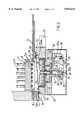
- FIG. 2is a side view of a moistening device mounted on the dispensing machine of FIG. 1, shown in a position in which the dispensing nozzles are isolated, most of the device being shown in longitudinal section for greater clarity,
- FIG. 3is a side view similar to that of FIG. 2, in which the moistening device is shown in a position in which the nozzles are partially uncovered, and
- FIG. 4is a sectioned view of a variant of a detail of the device of the present invention.
- an automatic dispensing machine 1comprises a space 2 defined at the bottom by a shelf 3 for the positioning of a container R, into which predefined quantities of fluid products, particularly dyes, bases, inks, pigments and the like are to be dispensed.
- a container Rfor the positioning of a container R, into which predefined quantities of fluid products, particularly dyes, bases, inks, pigments and the like are to be dispensed.
- an automatic dispensing machineis referred to herein, the invention may also be used on semi-automatic or manual machines. The invention is applicable, in general, to any dispensing machine of known type, regardless of its configuration and its specific dimensions.
- the upper portion of the space 2is closed by a horizontal plate 4 (see FIGS. 2 and 3) from which the ends 5a of dispensing pipes 5 project, the pipes extending through the base 6 of a nozzle-center body 7 which preferably, but in non-limiting manner, is shaped as an inverted cup.
- the ends 5aconstitute the dispensing nozzles of the dispensing machine but, naturally, the manner in which these nozzles are formed may vary widely according to the characteristics of the dispensing machine on which they are mounted and they may thus adopt any form known to experts in the art.
- the height of a peripheral wall 8 of the nozzle center-body 7is a little greater than the distance by which nozzles 5a project from the base 6.
- the height of the peripheral wall 8could be reduced to a minimum or it may not even be present.
- peripheral wall 8may also be entirely missing.
- annular body 9Fixed to the lower portion of the plate 4 is an annular body 9, the lower wall 10 of which is inclined to the horizontal and has a recess in which an annular seal 11 is mounted.
- the slide 13is moved by means of a linear actuator (not shown in the drawings) or by means of any other movement device of known type. In the simplest cases, the slide may even be moved manually.
- Engagement devicesmay also be provided for locking the slide in the position in which the nozzles are covered and/or in the position in which they are uncovered.
- the movement of the slidemay be assisted or opposed by the provision of resilient reaction means, in a known configuration.
- the slide 13supports a dish-like body 14 comprising a cavity 14a, the base of which has a hole through which a rod 15 can extend to drive a perforated plate 16 to which a disc 17, preferably of absorbent material such as felt, sponge, natural or synthetic fibers or the like, is fixed in turn.
- a seal 23allows the rod 15 to slide in a leaktight manner.
- the absorbent elementmay be cup-shaped and its upper edge, indicated 34, may be made of resilient or flexible material so as to form a ring for sealing the closed chamber, indicated 36, against the base 35 of the body 32. Moreover, this upper edge may not be made of resilient or flexible material.
- the nozzle-center bodyhas no peripheral walls, it is possible to form in the upper surface of the absorbent element notches, recesses, or generic shapings to be located in the region of the nozzles so as to form a plurality of small chambers when the absorbent element is in contact with the nozzle-center body 7.
- a tube 18 for guiding the rod 15is fixed below the dish-like body 14 in the region of the central hole.
- Two diametrally-opposed vertical slots 19are formed in the side walls of the tube 18 and a transverse pin 20 inserted therein extends through a corresponding transverse hole in the rod 15 and projects from both sides of the tube 18.
- An annular plate 21 mounted for sliding on the tube 18has transverse holes through which the pin 20 can extend, the pin 20 thus being fixed to the rod 15 and to the plate 21 and being movable vertically relative to the tube 18 within the range defined by the extent of the slots 19.
- a helical spring 22is interposed between the base of the dish-like body 14 and the annular plate 21.
- transverse pin 20The ends of the transverse pin 20 are inserted in two further slots 24 disposed at the ends 25a of two L-shaped levers 25 (only one of which is shown in FIGS. 2 and 3) which are articulated in their central regions to an appendage 26 projecting downwards from the dish-like body 14.
- a transverse bar 27 with a circular cross-sectionis mounted on the levers 25 so as to join their two ends 25b opposite the ends 25a with the slots 24.
- the axis of the bar 27is preferably arranged eccentrically relative to the point 28 at which the bar is fixed to the levers.
- a check block 29is mounted on an appendage 30 disposed in a predetermined fixed position relative to the guides 12 and hence to the plate 4 and to the nozzles 5a.
- the check block 29has a circular cross-section and is mounted so that its horizontal axis is eccentric relative to the point at which it is fixed to the appendage 30.
- the cavity 14a of the dish-like body 14is filled with a moistening liquid such as water.
- a moistening liquidsuch as water.
- the liquid held in the cavity 14amay be a known solvent other than water.
- the absorbent disc 17, impregnated with moistening liquid as described further belowcloses the opening of the nozzle-center body 7 so as to define a closed chamber 31 in which the nozzles 5a are disposed.
- the volume of air imprisoned inside the closed chamber 31is quickly saturated by the vapors of the liquid with which the absorbent disc 17 is impregnated, thus preventing the fluid in the nozzles 5a from drying.
- the fact that the upper surface of the disc 17 is spaced, albeit slightly, from the nozzles 5aprevents any residues or drops of fluid coming out of one of the nozzles 5a and spreading out by capillarity on the absorbent disc 17 from reaching one or more of the other nozzles and being mixed with the fluid therein, contaminating it.
- a similar resultcan be achieved by means of the small chambers described above.
- the absorbent disc 17is kept pressed against the opening of the nozzle-center body 7 by virtue of the thrust exerted by the perforated plate 16 and by the rod 15 by means of the pin 20 which is held in the position shown by the L-shaped levers 25.
- the position of the slide 13is in fact such that the bar 27 is in abutment with the block 29 and keeps the levers 25 pivoted, in opposition to the resilient force exerted by the spring 22.
- the pressure of the absorbent disc 17 on the opening of the nozzle-center body 7can be regulated by adjustment of the eccentric positions of the bar 28 and of the block 29 so as to take up any play due to the continued use over a period of time of the same absorbent disc 17 which, by its nature, tends to become squashed and in which an ever more marked annular imprint is progressively formed.
- the slide 13When fluids are to be dispensed into the container R, the slide 13 is moved, automatically or manually, in the direction of the arrow A of FIG. 2 so as to move apart the surfaces 10, 13a of the annular body 9 and of the slide 13, respectively.
- the movement of the slide 13allows the levers 25 to pivot anticlockwise under the thrust exerted by the spring 22 which presses against the plate 21 which entrains the pin 20 downwards.
- the rod 15is thus urged downwards, entraining with it the perforated plate 16 and the absorbent disc 17.
- the perforated plate 16is plunged into the cavity 14a and the liquid therein can impregnate the absorbent disc 17, passing through the holes in the perforated plate 16.
- the spring 22could be replaced by any resilient element of known type and could also be eliminated with the provision, in its place, of a spring acting directly on the levers 25, for example, a torsion spring wound around the articulation axis of the levers on the appendage 26.
- the number, arrangement and configuration of the levers 25 and of all of the members for transmitting the movement to the perforated plate 16 in generalmay also be modified on the basis of normal design criteria within the capability of any expert in the art.
- the actuator means which drive the absorbent elementmay be hydraulic, pneumatic, electromechanical, etc., and may even be manual.
- the diameter of the absorbent disc 17could be larger than that of the opening, or could substantially correspond thereto, so that it could be fitted inside the opening with minimal interference.
- a variant of the device of the present inventionprovides for the elimination of the moistening liquid or solvent and possibly of the perforated plate 16 and for the replacement of the absorbent disc 17 with a hermetic, rigid, resilient or generally flexible plug.
- an important characteristic of the device according to the present inventionis the presence of a double seal; the first seal 11 isolates the dish-like body 14 from the outside atmosphere to prevent evaporation of the liquid in the cavity 14a or of the liquid absorbed by the disc 17 through the perforated plate 16, whilst the second seal is formed by the abutment of the disc 17 against the nozzle-center body 7 in order to maintain the saturation of the volume of air, even though it is small, in the chamber in which the ends 5a of the nozzles 5 emerge.
Landscapes
- Chemical & Material Sciences (AREA)
- Chemical Kinetics & Catalysis (AREA)
- Coating Apparatus (AREA)
- Nozzles (AREA)
Abstract
Description
Claims (14)
Applications Claiming Priority (2)
| Application Number | Priority Date | Filing Date | Title |
|---|---|---|---|
| IT96MI000601AIT1283307B1 (en) | 1996-03-27 | 1996-03-27 | HUMIDIFIER DEVICE FOR FLUID DISPENSING NOZZLES OF A DISPENSING MACHINE. |
| ITMI96A0601 | 1996-03-27 |
Publications (1)
| Publication Number | Publication Date |
|---|---|
| US5842641Atrue US5842641A (en) | 1998-12-01 |
Family
ID=11373785
Family Applications (1)
| Application Number | Title | Priority Date | Filing Date |
|---|---|---|---|
| US08/805,056Expired - LifetimeUS5842641A (en) | 1996-03-27 | 1997-02-24 | Device for moistening fluid-dispensing nozzles of a dispensing machine |
Country Status (2)
| Country | Link |
|---|---|
| US (1) | US5842641A (en) |
| IT (1) | IT1283307B1 (en) |
Cited By (31)
| Publication number | Priority date | Publication date | Assignee | Title |
|---|---|---|---|---|
| US6116518A (en)* | 1997-10-27 | 2000-09-12 | G.D S.P.A. | Spray gumming unit |
| US20020002934A1 (en)* | 2000-02-18 | 2002-01-10 | Nungesser Edwin Hugh | Stable mixtures containing opacifying pigments |
| US20030110101A1 (en)* | 2000-02-18 | 2003-06-12 | Friel John Michael | Distributed paint manufacturing system |
| US6622064B2 (en)* | 2000-03-31 | 2003-09-16 | Imx Labs, Inc. | Nail polish selection method |
| WO2003082728A1 (en) | 2002-03-28 | 2003-10-09 | Cps Color Equipment S.P.A. | Conditioning equipment for a dispensing head in a colouring agent dispensing machine |
| US6689824B2 (en) | 2000-02-18 | 2004-02-10 | Rohm And Haas Company | Prepaints and method of preparing road-marking paints from prepaints |
| US20040059041A1 (en)* | 1998-12-23 | 2004-03-25 | Mcclain C. Daniel | Method and apparatus for producing an aqueous paint composition from a plurality of premixed compositions |
| US20040056111A1 (en)* | 2000-09-04 | 2004-03-25 | Pentti Airaksinen | Apparatus for preventing drying of nozzle in fluid dispensing device |
| US20050205154A1 (en)* | 2004-03-16 | 2005-09-22 | Cleveland James R | Articulated nozzle closure for fluid dispensers |
| FR2867768A1 (en)* | 2004-03-22 | 2005-09-23 | Claude Olmos | Colorant filling head for use in paint preparing machine, has body movably assembled inside cutting tool to cause cutting of paint container that is filled, by body displacement, inside tool towards container |
| US20050252934A1 (en)* | 2004-05-12 | 2005-11-17 | Miller William A | Apparatus for dispensing paint and stain samples and methods of dispensing paint and stain samples |
| US7082970B2 (en) | 2001-09-24 | 2006-08-01 | Bartholomew Julie R | Apparatus and method for custom cosmetic dispensing |
| US20070012376A1 (en)* | 2005-07-15 | 2007-01-18 | Fluid Management Operations Llc | Multiple fluid dispenser |
| WO2006106102A3 (en)* | 2005-04-05 | 2007-11-15 | Cps Color Equipment Spa Con Un | Device and method for preventing the drying of fluid products in a dispensing machine for such products |
| WO2008109514A1 (en)* | 2007-03-02 | 2008-09-12 | Ultrablend, Llc | Apparatus and method for humidifying a nozzle of a colorant dispenser |
| US20080223480A1 (en)* | 2007-03-14 | 2008-09-18 | Fluid Management, Inc. | Manually Operable Manifold/Nozzle Closure for Fluid Dispenser |
| US20090099695A1 (en)* | 1998-12-23 | 2009-04-16 | Microblend Technologies, Inc. | Color integrated and mobile paint systems for producing paint from a plurality of prepaint components |
| US20090099694A1 (en)* | 1998-12-23 | 2009-04-16 | Microblend Technologies, Inc. | Color integrated and mobile paint systems for producing paint from a plurality of prepaint components |
| US20090112371A1 (en)* | 2007-06-01 | 2009-04-30 | Hughes Randall L | Method and apparatus for producing paint |
| US7624769B2 (en) | 2004-11-08 | 2009-12-01 | Cosmetic Technologies, L.L.C. | Automated customized cosmetic dispenser |
| US7698021B2 (en) | 2007-06-01 | 2010-04-13 | Microblend Technologies, Inc. | Method and apparatus for producing paint |
| US8014885B2 (en) | 1998-12-23 | 2011-09-06 | Microblend Technologies, Inc. | Mobile paint system utilizing slider attribute prompts and reflectance memory storage |
| US8017137B2 (en) | 2004-07-19 | 2011-09-13 | Bartholomew Julie R | Customized retail point of sale dispensing methods |
| US20130158704A1 (en)* | 2011-12-16 | 2013-06-20 | Randall L. Hughes | Method and apparatus for producing paint |
| US8573263B2 (en) | 2001-09-24 | 2013-11-05 | Cosmetic Technologies, Llc | Apparatus and method for custom cosmetic dispensing |
| US20130313134A1 (en)* | 2010-06-24 | 2013-11-28 | Cps Color Equipment Spa Con Unico Socio | Anti-drying device |
| WO2014013315A1 (en) | 2012-07-20 | 2014-01-23 | Cps Color Equipment Spa Con Unico Socio | Device to prevent the drying of nozzles of a machine for the preparation of fluid coloring products |
| US8636173B2 (en) | 2001-06-01 | 2014-01-28 | Cosmetic Technologies, L.L.C. | Point-of-sale body powder dispensing system |
| IT201900022872A1 (en)* | 2019-12-03 | 2021-06-03 | Dromont S P A | AUTOMATIC HUMIDIFICATION SYSTEM OF A DISPENSING HEAD OF A FLUID PRODUCT DOSING MACHINE |
| US11412835B2 (en) | 2015-06-08 | 2022-08-16 | Cosmetic Technologies, L.L.C. | Automated delivery system of a cosmetic sample |
| US20230024076A1 (en)* | 2021-07-21 | 2023-01-26 | Yotta Innovation Co., Ltd. | Snowboard fixing frame |
Citations (1)
| Publication number | Priority date | Publication date | Assignee | Title |
|---|---|---|---|---|
| JPH06226147A (en)* | 1993-02-02 | 1994-08-16 | Seikosha Co Ltd | Fluid discharge device |
- 1996
- 1996-03-27ITIT96MI000601Apatent/IT1283307B1/enactiveIP Right Grant
- 1997
- 1997-02-24USUS08/805,056patent/US5842641A/ennot_activeExpired - Lifetime
Patent Citations (1)
| Publication number | Priority date | Publication date | Assignee | Title |
|---|---|---|---|---|
| JPH06226147A (en)* | 1993-02-02 | 1994-08-16 | Seikosha Co Ltd | Fluid discharge device |
Cited By (76)
| Publication number | Priority date | Publication date | Assignee | Title |
|---|---|---|---|---|
| US6116518A (en)* | 1997-10-27 | 2000-09-12 | G.D S.P.A. | Spray gumming unit |
| US20060148967A1 (en)* | 1998-12-23 | 2006-07-06 | Mcclain C D | Method and apparatus for producing an aqueous paint composition from a plurality of premixed compositions |
| US7132470B2 (en) | 1998-12-23 | 2006-11-07 | Coatings Management Systems, Inc. | Method and apparatus for producing an aqueous paint composition from a plurality of premixed compositions |
| US20080146699A1 (en)* | 1998-12-23 | 2008-06-19 | Coatings Management Systems Inc. | Method and apparatus for producing an aqueous paint composition from a plurality of premixed compositions |
| US20080257220A1 (en)* | 1998-12-23 | 2008-10-23 | Coatings Management Systems Inc. | Method and apparatus for producing an aqueous paint composition from a plurality of premixed compositions |
| US8014885B2 (en) | 1998-12-23 | 2011-09-06 | Microblend Technologies, Inc. | Mobile paint system utilizing slider attribute prompts and reflectance memory storage |
| US7951855B2 (en) | 1998-12-23 | 2011-05-31 | Microblend Technologies, Inc. | Color integrated and mobile paint systems for producing paint from a plurality of prepaint components |
| US7654727B2 (en) | 1998-12-23 | 2010-02-02 | Coatings Management Systems, Inc. | Method and apparatus for producing an aqueous paint composition from a plurality of premixed compositions |
| US6969190B1 (en) | 1998-12-23 | 2005-11-29 | Coatings Management Systems, Inc. | Method and apparatus for producing an aqueous paint composition from a plurality of premixed compositions |
| US20040059041A1 (en)* | 1998-12-23 | 2004-03-25 | Mcclain C. Daniel | Method and apparatus for producing an aqueous paint composition from a plurality of premixed compositions |
| US7695185B1 (en) | 1998-12-23 | 2010-04-13 | Coatings Management Systems, Inc. | Method and apparatus for producing an aqueous paint composition from a plurality of premixed compositions |
| US20090099695A1 (en)* | 1998-12-23 | 2009-04-16 | Microblend Technologies, Inc. | Color integrated and mobile paint systems for producing paint from a plurality of prepaint components |
| US7339000B1 (en) | 1998-12-23 | 2008-03-04 | Coatings Management Systems Inc. | Method and apparatus for producing an aqueous paint composition from a plurality of premixed compositions |
| US7065429B1 (en) | 1998-12-23 | 2006-06-20 | Microblend Technologies, Inc. | Method and apparatus for producing an aqueous paint composition from a plurality of premixed compositions |
| US7619023B2 (en) | 1998-12-23 | 2009-11-17 | Coatings Management Systems, Inc. | Method and apparatus for producing an aqueous paint composition from a plurality of premixed compositions |
| US20090099694A1 (en)* | 1998-12-23 | 2009-04-16 | Microblend Technologies, Inc. | Color integrated and mobile paint systems for producing paint from a plurality of prepaint components |
| US6919400B2 (en) | 2000-02-18 | 2005-07-19 | Rohm And Haas Company | Stable mixtures containing opacifying pigments |
| US7612129B2 (en) | 2000-02-18 | 2009-11-03 | Rohm And Haas Company | Distributed paint manufacturing system |
| US6689824B2 (en) | 2000-02-18 | 2004-02-10 | Rohm And Haas Company | Prepaints and method of preparing road-marking paints from prepaints |
| US6531537B2 (en) | 2000-02-18 | 2003-03-11 | John Michael Friel | Prepaints and methods of preparing paints from the prepaints |
| US20020002934A1 (en)* | 2000-02-18 | 2002-01-10 | Nungesser Edwin Hugh | Stable mixtures containing opacifying pigments |
| US20040030035A1 (en)* | 2000-02-18 | 2004-02-12 | Friel John Michael | Premixes and method of preparing adhesives ad caulks from premixes |
| US6613832B2 (en) | 2000-02-18 | 2003-09-02 | Rohm And Haas Company | Premixes and method of preparing adhesives and caulks from premixes |
| US20030110101A1 (en)* | 2000-02-18 | 2003-06-12 | Friel John Michael | Distributed paint manufacturing system |
| US7250464B2 (en) | 2000-02-18 | 2007-07-31 | Rohm And Haas Company | Distributed paint manufacturing system |
| US7099740B2 (en) | 2000-03-31 | 2006-08-29 | Bartholomew Julie R | Nail polish color selection system |
| US6622064B2 (en)* | 2000-03-31 | 2003-09-16 | Imx Labs, Inc. | Nail polish selection method |
| US8880218B2 (en) | 2000-03-31 | 2014-11-04 | Cosmetic Technologies, L.L.C. | Nail polish color selection system |
| US7395134B2 (en) | 2000-03-31 | 2008-07-01 | Cosmetic Technologies, L.L.C. | Nail polish color selection system |
| US7822504B2 (en) | 2000-03-31 | 2010-10-26 | Cosmetic Technologies, L.L.C. | Nail polish color selection system |
| US8352070B2 (en) | 2000-03-31 | 2013-01-08 | Cosmetic Technologies, Llc | Nail polish color selection system |
| EP2000089A1 (en) | 2000-03-31 | 2008-12-10 | Cosmetic Technologies LLC | Nail polish color selection system and method |
| US6843431B2 (en) | 2000-09-04 | 2005-01-18 | Cps Color Group Oy | Apparatus for preventing drying of nozzle in fluid dispensing device |
| US20040056111A1 (en)* | 2000-09-04 | 2004-03-25 | Pentti Airaksinen | Apparatus for preventing drying of nozzle in fluid dispensing device |
| US8636173B2 (en) | 2001-06-01 | 2014-01-28 | Cosmetic Technologies, L.L.C. | Point-of-sale body powder dispensing system |
| US8141596B2 (en) | 2001-09-24 | 2012-03-27 | Cosmetic Technologies Llc | Apparatus and method for custom cosmetic dispensing |
| US7475710B2 (en) | 2001-09-24 | 2009-01-13 | Bartholomew Julie R | Apparatus and method for custom cosmetic dispensing |
| US7082970B2 (en) | 2001-09-24 | 2006-08-01 | Bartholomew Julie R | Apparatus and method for custom cosmetic dispensing |
| US8573263B2 (en) | 2001-09-24 | 2013-11-05 | Cosmetic Technologies, Llc | Apparatus and method for custom cosmetic dispensing |
| WO2003082728A1 (en) | 2002-03-28 | 2003-10-09 | Cps Color Equipment S.P.A. | Conditioning equipment for a dispensing head in a colouring agent dispensing machine |
| US20050205154A1 (en)* | 2004-03-16 | 2005-09-22 | Cleveland James R | Articulated nozzle closure for fluid dispensers |
| US7261131B2 (en) | 2004-03-16 | 2007-08-28 | Fluid Management, Inc. | Articulated nozzle closure for fluid dispensers |
| FR2867768A1 (en)* | 2004-03-22 | 2005-09-23 | Claude Olmos | Colorant filling head for use in paint preparing machine, has body movably assembled inside cutting tool to cause cutting of paint container that is filled, by body displacement, inside tool towards container |
| US20050252934A1 (en)* | 2004-05-12 | 2005-11-17 | Miller William A | Apparatus for dispensing paint and stain samples and methods of dispensing paint and stain samples |
| US7228879B2 (en) | 2004-05-12 | 2007-06-12 | Fluid Management, Inc. | Apparatus for dispensing paint and stain samples and methods of dispensing paint and stain samples |
| US8017137B2 (en) | 2004-07-19 | 2011-09-13 | Bartholomew Julie R | Customized retail point of sale dispensing methods |
| US7624769B2 (en) | 2004-11-08 | 2009-12-01 | Cosmetic Technologies, L.L.C. | Automated customized cosmetic dispenser |
| US9984526B2 (en) | 2004-11-08 | 2018-05-29 | Cosmetic Technologies, L.L.C. | Automated customized cosmetic dispenser |
| US9691213B2 (en) | 2004-11-08 | 2017-06-27 | Cosmetic Technologies, L.L.C. | Automated customized cosmetic dispenser |
| US8608371B2 (en) | 2004-11-08 | 2013-12-17 | Cosmetic Technologies, Llc | Automated customized cosmetic dispenser |
| US8186872B2 (en) | 2004-11-08 | 2012-05-29 | Cosmetic Technologies | Automated customized cosmetic dispenser |
| US20080264452A1 (en)* | 2005-04-05 | 2008-10-30 | Cps Color Equipment Spa Con Unico Socio | Device and Method for Preventing the Drying of Fluid Products in a Dispensing Machine for Such Products |
| WO2006106102A3 (en)* | 2005-04-05 | 2007-11-15 | Cps Color Equipment Spa Con Un | Device and method for preventing the drying of fluid products in a dispensing machine for such products |
| US7905240B2 (en) | 2005-04-05 | 2011-03-15 | Cps Color Equipment Spa Con Unico Socio | Device and method for preventing the drying of fluid products in a dispensing machine for such products |
| JP2008538530A (en)* | 2005-04-05 | 2008-10-30 | シーピーエス・カラー・イクウィップメント・ソシエタ・ペル・アチオニ・コン・ユニコ・ソシオ | Apparatus and method for preventing drying of fluid products in a distributor for fluid products |
| US20070012376A1 (en)* | 2005-07-15 | 2007-01-18 | Fluid Management Operations Llc | Multiple fluid dispenser |
| US7562680B2 (en)* | 2005-07-15 | 2009-07-21 | Fluid Management Operations, Llc | Multiple fluid dispenser |
| WO2008109514A1 (en)* | 2007-03-02 | 2008-09-12 | Ultrablend, Llc | Apparatus and method for humidifying a nozzle of a colorant dispenser |
| US7581571B2 (en)* | 2007-03-14 | 2009-09-01 | Fluid Managment Operations, Llc | Manually operable manifold/nozzle closure for fluid dispenser |
| US20080223480A1 (en)* | 2007-03-14 | 2008-09-18 | Fluid Management, Inc. | Manually Operable Manifold/Nozzle Closure for Fluid Dispenser |
| US7865264B2 (en) | 2007-06-01 | 2011-01-04 | Microblend Techologies, Inc. | Method and apparatus for matching amount and type of paint component in a paint manufacturing system |
| US20090112371A1 (en)* | 2007-06-01 | 2009-04-30 | Hughes Randall L | Method and apparatus for producing paint |
| US7698021B2 (en) | 2007-06-01 | 2010-04-13 | Microblend Technologies, Inc. | Method and apparatus for producing paint |
| US20130313134A1 (en)* | 2010-06-24 | 2013-11-28 | Cps Color Equipment Spa Con Unico Socio | Anti-drying device |
| US8936390B2 (en)* | 2011-12-16 | 2015-01-20 | Microblend Technologies, Inc. | Method and apparatus for producing paint |
| US20150124553A1 (en)* | 2011-12-16 | 2015-05-07 | Microblend Technologies, Inc. | Method and apparatus for producing paint |
| US9211514B2 (en)* | 2011-12-16 | 2015-12-15 | Microblend Technologies, Inc. | Method and apparatus for producing paint |
| US20130158704A1 (en)* | 2011-12-16 | 2013-06-20 | Randall L. Hughes | Method and apparatus for producing paint |
| WO2014013315A1 (en) | 2012-07-20 | 2014-01-23 | Cps Color Equipment Spa Con Unico Socio | Device to prevent the drying of nozzles of a machine for the preparation of fluid coloring products |
| US9925551B2 (en) | 2012-07-20 | 2018-03-27 | Corob S.P.A. Con Socio Unico | Device to prevent the drying of nozzles of a machine for the preparation of fluid coloring products |
| EP3685926A1 (en) | 2012-07-20 | 2020-07-29 | Corob S.P.A. | Machine for the preparation of fluid coloring products |
| US11412835B2 (en) | 2015-06-08 | 2022-08-16 | Cosmetic Technologies, L.L.C. | Automated delivery system of a cosmetic sample |
| IT201900022872A1 (en)* | 2019-12-03 | 2021-06-03 | Dromont S P A | AUTOMATIC HUMIDIFICATION SYSTEM OF A DISPENSING HEAD OF A FLUID PRODUCT DOSING MACHINE |
| EP3838430A1 (en)* | 2019-12-03 | 2021-06-23 | Dromont S.p.A. | An automatic humidification system for a dispensing head of a dosing machine of fluid products |
| US11951503B2 (en) | 2019-12-03 | 2024-04-09 | Dromont S.P.A. | Automatic humidification system for a dispensing head of a dosing machine of fluid products |
| US20230024076A1 (en)* | 2021-07-21 | 2023-01-26 | Yotta Innovation Co., Ltd. | Snowboard fixing frame |
Also Published As
| Publication number | Publication date |
|---|---|
| ITMI960601A1 (en) | 1997-09-27 |
| IT1283307B1 (en) | 1998-04-16 |
| ITMI960601A0 (en) | 1996-03-27 |
Similar Documents
| Publication | Publication Date | Title |
|---|---|---|
| US5842641A (en) | Device for moistening fluid-dispensing nozzles of a dispensing machine | |
| EP1242295B1 (en) | Dispensing apparatus | |
| US5085347A (en) | Pressurized dispenser package | |
| US4061247A (en) | Method of and apparatus for controlling of travel of the plunger in a dispensing pump chamber | |
| US5598954A (en) | Door actuated device for dispensing fluid from a container | |
| CA1036557A (en) | Product dispensing device | |
| JPH0375228B2 (en) | ||
| CA1303569C (en) | Pump dispenser | |
| GB2437510A (en) | Dispenser mechanism | |
| KR100462967B1 (en) | Dispenser for liquid or pasty materials | |
| KR20030093189A (en) | Dosing pump for liquid dispensers | |
| CZ153199A3 (en) | Pumping dosing apparatus | |
| JPH0784227B2 (en) | Metering valve for aerosol dispensing | |
| WO2007037597A1 (en) | Dispensing apparatus and liquid dispensing container having the same | |
| US4886186A (en) | Paste dispenser | |
| AU2694092A (en) | Actuator and hood for dispensing device | |
| EP0691161B1 (en) | A device for dispensing pastes or liquids from bottles or the like | |
| US3664548A (en) | Aerosol containers and valves thereof | |
| US3520450A (en) | Fluids dispensing valve | |
| DE3460256D1 (en) | Room spray dispenser | |
| EP0197281B1 (en) | Liquid applicator device | |
| US5788123A (en) | Dispenser for the controlled discharge of a fluid medium | |
| CN1055157A (en) | Measure the foam actuator of aerosol product | |
| KR102611185B1 (en) | Dispenser device without air intake for applicator tips for various types of flexible packaging | |
| US5248212A (en) | Dispenser with valve actuated by a deformable wall thereof |
Legal Events
| Date | Code | Title | Description |
|---|---|---|---|
| AS | Assignment | Owner name:COROB S.P.A., ITALY Free format text:ASSIGNMENT OF ASSIGNORS INTEREST;ASSIGNOR:MAZZALVERI, LEOPOLDO;REEL/FRAME:008483/0217 Effective date:19970116 | |
| STCF | Information on status: patent grant | Free format text:PATENTED CASE | |
| FEPP | Fee payment procedure | Free format text:PAYOR NUMBER ASSIGNED (ORIGINAL EVENT CODE: ASPN); ENTITY STATUS OF PATENT OWNER: LARGE ENTITY | |
| FEPP | Fee payment procedure | Free format text:PAT HOLDER NO LONGER CLAIMS SMALL ENTITY STATUS, ENTITY STATUS SET TO UNDISCOUNTED (ORIGINAL EVENT CODE: STOL); ENTITY STATUS OF PATENT OWNER: LARGE ENTITY | |
| REFU | Refund | Free format text:REFUND - PAYMENT OF MAINTENANCE FEE, 4TH YR, SMALL ENTITY (ORIGINAL EVENT CODE: R283); ENTITY STATUS OF PATENT OWNER: LARGE ENTITY | |
| FPAY | Fee payment | Year of fee payment:4 | |
| FEPP | Fee payment procedure | Free format text:PAYER NUMBER DE-ASSIGNED (ORIGINAL EVENT CODE: RMPN); ENTITY STATUS OF PATENT OWNER: LARGE ENTITY Free format text:PAYOR NUMBER ASSIGNED (ORIGINAL EVENT CODE: ASPN); ENTITY STATUS OF PATENT OWNER: LARGE ENTITY | |
| FEPP | Fee payment procedure | Free format text:PAYER NUMBER DE-ASSIGNED (ORIGINAL EVENT CODE: RMPN); ENTITY STATUS OF PATENT OWNER: LARGE ENTITY Free format text:PAYOR NUMBER ASSIGNED (ORIGINAL EVENT CODE: ASPN); ENTITY STATUS OF PATENT OWNER: LARGE ENTITY | |
| FEPP | Fee payment procedure | Free format text:PAYER NUMBER DE-ASSIGNED (ORIGINAL EVENT CODE: RMPN); ENTITY STATUS OF PATENT OWNER: LARGE ENTITY Free format text:PAYOR NUMBER ASSIGNED (ORIGINAL EVENT CODE: ASPN); ENTITY STATUS OF PATENT OWNER: LARGE ENTITY | |
| FPAY | Fee payment | Year of fee payment:8 | |
| FPAY | Fee payment | Year of fee payment:12 |