US5842479A - Method of restoring reduced or absent blood flow capacity - Google Patents
Method of restoring reduced or absent blood flow capacityDownload PDFInfo
- Publication number
- US5842479A US5842479AUS08/730,421US73042196AUS5842479AUS 5842479 AUS5842479 AUS 5842479AUS 73042196 AUS73042196 AUS 73042196AUS 5842479 AUS5842479 AUS 5842479A
- Authority
- US
- United States
- Prior art keywords
- artery
- vascular graft
- segment
- graft
- arteriotomy
- Prior art date
- Legal status (The legal status is an assumption and is not a legal conclusion. Google has not performed a legal analysis and makes no representation as to the accuracy of the status listed.)
- Expired - Fee Related
Links
- 238000000034methodMethods0.000titleclaimsabstractdescription41
- 230000017531blood circulationEffects0.000titledescription12
- 210000001367arteryAnatomy0.000claimsabstractdescription176
- 230000002792vascularEffects0.000claimsdescription154
- 239000000463materialSubstances0.000claimsdescription44
- 238000003780insertionMethods0.000claimsdescription17
- 230000037431insertionEffects0.000claimsdescription17
- 238000002399angioplastyMethods0.000claimsdescription9
- 230000000149penetrating effectEffects0.000claims8
- 230000006835compressionEffects0.000claims5
- 238000007906compressionMethods0.000claims5
- 206010003210ArteriosclerosisDiseases0.000abstractdescription48
- 208000037260Atherosclerotic PlaqueDiseases0.000abstractdescription48
- 208000037803restenosisDiseases0.000abstractdescription6
- 230000002401inhibitory effectEffects0.000abstract1
- 210000001519tissueAnatomy0.000description17
- 238000013171endarterectomyMethods0.000description16
- 210000002808connective tissueAnatomy0.000description15
- 210000001105femoral arteryAnatomy0.000description12
- 238000002604ultrasonographyMethods0.000description12
- 239000010410layerSubstances0.000description10
- 238000000576coating methodMethods0.000description9
- 239000011248coating agentSubstances0.000description8
- 230000002787reinforcementEffects0.000description8
- 238000011282treatmentMethods0.000description8
- 208000031481Pathologic ConstrictionDiseases0.000description6
- 210000004231tunica mediaAnatomy0.000description6
- 238000011144upstream manufacturingMethods0.000description6
- 230000008901benefitEffects0.000description5
- 210000003127kneeAnatomy0.000description5
- 208000037804stenosisDiseases0.000description5
- 230000002966stenotic effectEffects0.000description5
- 230000004872arterial blood pressureEffects0.000description4
- 238000006073displacement reactionMethods0.000description4
- 230000000694effectsEffects0.000description4
- 230000036262stenosisEffects0.000description4
- 210000004026tunica intimaAnatomy0.000description4
- 201000010099diseaseDiseases0.000description3
- 208000037265diseases, disorders, signs and symptomsDiseases0.000description3
- 239000004810polytetrafluoroethyleneSubstances0.000description3
- 229920001343polytetrafluoroethylenePolymers0.000description3
- 230000000717retained effectEffects0.000description3
- 210000003462veinAnatomy0.000description3
- 102000008186CollagenHuman genes0.000description2
- 108010035532CollagenProteins0.000description2
- 229920004934Dacron®Polymers0.000description2
- 239000008280bloodSubstances0.000description2
- 210000004369bloodAnatomy0.000description2
- 229920001436collagenPolymers0.000description2
- 238000010276constructionMethods0.000description2
- -1e.g.Substances0.000description2
- 239000004744fabricSubstances0.000description2
- 230000008595infiltrationEffects0.000description2
- 238000001764infiltrationMethods0.000description2
- 210000000629knee jointAnatomy0.000description2
- 230000003902lesionEffects0.000description2
- 239000007788liquidSubstances0.000description2
- 239000005020polyethylene terephthalateSubstances0.000description2
- 238000011084recoveryMethods0.000description2
- 230000003014reinforcing effectEffects0.000description2
- 206010002091AnaesthesiaDiseases0.000description1
- 206010002329AneurysmDiseases0.000description1
- 206010060965Arterial stenosisDiseases0.000description1
- 229920000544Gore-TexPolymers0.000description1
- 241001465754MetazoaSpecies0.000description1
- 239000004677NylonSubstances0.000description1
- 239000004743PolypropyleneSubstances0.000description1
- 230000004913activationEffects0.000description1
- 230000037005anaesthesiaEffects0.000description1
- 210000003484anatomyAnatomy0.000description1
- 230000008321arterial blood flowEffects0.000description1
- 230000004888barrier functionEffects0.000description1
- 210000000746body regionAnatomy0.000description1
- 238000013276bronchoscopyMethods0.000description1
- 230000015556catabolic processEffects0.000description1
- 230000000916dilatatory effectEffects0.000description1
- 230000002526effect on cardiovascular systemEffects0.000description1
- 210000003038endotheliumAnatomy0.000description1
- 238000005516engineering processMethods0.000description1
- 238000000605extractionMethods0.000description1
- 238000011010flushing procedureMethods0.000description1
- 238000000227grindingMethods0.000description1
- 210000004013groinAnatomy0.000description1
- 230000035876healingEffects0.000description1
- 238000007373indentationMethods0.000description1
- 229940127554medical productDrugs0.000description1
- 230000005012migrationEffects0.000description1
- 238000013508migrationMethods0.000description1
- 238000002324minimally invasive surgeryMethods0.000description1
- 229920001778nylonPolymers0.000description1
- 239000013307optical fiberSubstances0.000description1
- 230000007170pathologyEffects0.000description1
- 229920001155polypropylenePolymers0.000description1
- 230000008569processEffects0.000description1
- 230000000306recurrent effectEffects0.000description1
- 230000009467reductionEffects0.000description1
- 230000037390scarringEffects0.000description1
- 238000000926separation methodMethods0.000description1
- 239000002356single layerSubstances0.000description1
- 239000007787solidSubstances0.000description1
- 239000007921spraySubstances0.000description1
- 238000005507sprayingMethods0.000description1
- 230000003068static effectEffects0.000description1
- 229920002994synthetic fiberPolymers0.000description1
- 230000009885systemic effectEffects0.000description1
- 239000012815thermoplastic materialSubstances0.000description1
Images


Classifications
- A—HUMAN NECESSITIES
- A61—MEDICAL OR VETERINARY SCIENCE; HYGIENE
- A61F—FILTERS IMPLANTABLE INTO BLOOD VESSELS; PROSTHESES; DEVICES PROVIDING PATENCY TO, OR PREVENTING COLLAPSING OF, TUBULAR STRUCTURES OF THE BODY, e.g. STENTS; ORTHOPAEDIC, NURSING OR CONTRACEPTIVE DEVICES; FOMENTATION; TREATMENT OR PROTECTION OF EYES OR EARS; BANDAGES, DRESSINGS OR ABSORBENT PADS; FIRST-AID KITS
- A61F2/00—Filters implantable into blood vessels; Prostheses, i.e. artificial substitutes or replacements for parts of the body; Appliances for connecting them with the body; Devices providing patency to, or preventing collapsing of, tubular structures of the body, e.g. stents
- A61F2/02—Prostheses implantable into the body
- A61F2/04—Hollow or tubular parts of organs, e.g. bladders, tracheae, bronchi or bile ducts
- A61F2/06—Blood vessels
- A61F2/07—Stent-grafts
- A—HUMAN NECESSITIES
- A61—MEDICAL OR VETERINARY SCIENCE; HYGIENE
- A61B—DIAGNOSIS; SURGERY; IDENTIFICATION
- A61B17/00—Surgical instruments, devices or methods
- A61B17/32—Surgical cutting instruments
- A61B17/3205—Excision instruments
- A61B17/3207—Atherectomy devices working by cutting or abrading; Similar devices specially adapted for non-vascular obstructions
- A61B17/320725—Atherectomy devices working by cutting or abrading; Similar devices specially adapted for non-vascular obstructions with radially expandable cutting or abrading elements
- A—HUMAN NECESSITIES
- A61—MEDICAL OR VETERINARY SCIENCE; HYGIENE
- A61B—DIAGNOSIS; SURGERY; IDENTIFICATION
- A61B17/00—Surgical instruments, devices or methods
- A61B17/32—Surgical cutting instruments
- A61B17/3205—Excision instruments
- A61B17/3207—Atherectomy devices working by cutting or abrading; Similar devices specially adapted for non-vascular obstructions
- A61B17/320758—Atherectomy devices working by cutting or abrading; Similar devices specially adapted for non-vascular obstructions with a rotating cutting instrument, e.g. motor driven
- A—HUMAN NECESSITIES
- A61—MEDICAL OR VETERINARY SCIENCE; HYGIENE
- A61F—FILTERS IMPLANTABLE INTO BLOOD VESSELS; PROSTHESES; DEVICES PROVIDING PATENCY TO, OR PREVENTING COLLAPSING OF, TUBULAR STRUCTURES OF THE BODY, e.g. STENTS; ORTHOPAEDIC, NURSING OR CONTRACEPTIVE DEVICES; FOMENTATION; TREATMENT OR PROTECTION OF EYES OR EARS; BANDAGES, DRESSINGS OR ABSORBENT PADS; FIRST-AID KITS
- A61F2/00—Filters implantable into blood vessels; Prostheses, i.e. artificial substitutes or replacements for parts of the body; Appliances for connecting them with the body; Devices providing patency to, or preventing collapsing of, tubular structures of the body, e.g. stents
- A61F2/02—Prostheses implantable into the body
- A61F2/04—Hollow or tubular parts of organs, e.g. bladders, tracheae, bronchi or bile ducts
- A61F2/06—Blood vessels
- A—HUMAN NECESSITIES
- A61—MEDICAL OR VETERINARY SCIENCE; HYGIENE
- A61F—FILTERS IMPLANTABLE INTO BLOOD VESSELS; PROSTHESES; DEVICES PROVIDING PATENCY TO, OR PREVENTING COLLAPSING OF, TUBULAR STRUCTURES OF THE BODY, e.g. STENTS; ORTHOPAEDIC, NURSING OR CONTRACEPTIVE DEVICES; FOMENTATION; TREATMENT OR PROTECTION OF EYES OR EARS; BANDAGES, DRESSINGS OR ABSORBENT PADS; FIRST-AID KITS
- A61F2/00—Filters implantable into blood vessels; Prostheses, i.e. artificial substitutes or replacements for parts of the body; Appliances for connecting them with the body; Devices providing patency to, or preventing collapsing of, tubular structures of the body, e.g. stents
- A61F2/95—Instruments specially adapted for placement or removal of stents or stent-grafts
- A61F2/954—Instruments specially adapted for placement or removal of stents or stent-grafts for placing stents or stent-grafts in a bifurcation
- A—HUMAN NECESSITIES
- A61—MEDICAL OR VETERINARY SCIENCE; HYGIENE
- A61B—DIAGNOSIS; SURGERY; IDENTIFICATION
- A61B17/00—Surgical instruments, devices or methods
- A61B17/00008—Vein tendon strippers
- A—HUMAN NECESSITIES
- A61—MEDICAL OR VETERINARY SCIENCE; HYGIENE
- A61B—DIAGNOSIS; SURGERY; IDENTIFICATION
- A61B17/00—Surgical instruments, devices or methods
- A61B17/064—Surgical staples, i.e. penetrating the tissue
- A—HUMAN NECESSITIES
- A61—MEDICAL OR VETERINARY SCIENCE; HYGIENE
- A61B—DIAGNOSIS; SURGERY; IDENTIFICATION
- A61B17/00—Surgical instruments, devices or methods
- A61B17/32—Surgical cutting instruments
- A61B17/3205—Excision instruments
- A61B17/3207—Atherectomy devices working by cutting or abrading; Similar devices specially adapted for non-vascular obstructions
- A61B17/32075—Pullback cutting; combined forward and pullback cutting, e.g. with cutters at both sides of the plaque
- A—HUMAN NECESSITIES
- A61—MEDICAL OR VETERINARY SCIENCE; HYGIENE
- A61B—DIAGNOSIS; SURGERY; IDENTIFICATION
- A61B17/00—Surgical instruments, devices or methods
- A61B17/22—Implements for squeezing-off ulcers or the like on inner organs of the body; Implements for scraping-out cavities of body organs, e.g. bones; for invasive removal or destruction of calculus using mechanical vibrations; for removing obstructions in blood vessels, not otherwise provided for
- A61B2017/22051—Implements for squeezing-off ulcers or the like on inner organs of the body; Implements for scraping-out cavities of body organs, e.g. bones; for invasive removal or destruction of calculus using mechanical vibrations; for removing obstructions in blood vessels, not otherwise provided for with an inflatable part, e.g. balloon, for positioning, blocking, or immobilisation
- A—HUMAN NECESSITIES
- A61—MEDICAL OR VETERINARY SCIENCE; HYGIENE
- A61B—DIAGNOSIS; SURGERY; IDENTIFICATION
- A61B17/00—Surgical instruments, devices or methods
- A61B17/32—Surgical cutting instruments
- A61B17/3205—Excision instruments
- A61B17/3207—Atherectomy devices working by cutting or abrading; Similar devices specially adapted for non-vascular obstructions
- A61B2017/320741—Atherectomy devices working by cutting or abrading; Similar devices specially adapted for non-vascular obstructions for stripping the intima or the internal plaque from a blood vessel, e.g. for endarterectomy
- A—HUMAN NECESSITIES
- A61—MEDICAL OR VETERINARY SCIENCE; HYGIENE
- A61B—DIAGNOSIS; SURGERY; IDENTIFICATION
- A61B90/00—Instruments, implements or accessories specially adapted for surgery or diagnosis and not covered by any of the groups A61B1/00 - A61B50/00, e.g. for luxation treatment or for protecting wound edges
- A61B90/06—Measuring instruments not otherwise provided for
- A61B2090/062—Measuring instruments not otherwise provided for penetration depth
- A—HUMAN NECESSITIES
- A61—MEDICAL OR VETERINARY SCIENCE; HYGIENE
- A61F—FILTERS IMPLANTABLE INTO BLOOD VESSELS; PROSTHESES; DEVICES PROVIDING PATENCY TO, OR PREVENTING COLLAPSING OF, TUBULAR STRUCTURES OF THE BODY, e.g. STENTS; ORTHOPAEDIC, NURSING OR CONTRACEPTIVE DEVICES; FOMENTATION; TREATMENT OR PROTECTION OF EYES OR EARS; BANDAGES, DRESSINGS OR ABSORBENT PADS; FIRST-AID KITS
- A61F2/00—Filters implantable into blood vessels; Prostheses, i.e. artificial substitutes or replacements for parts of the body; Appliances for connecting them with the body; Devices providing patency to, or preventing collapsing of, tubular structures of the body, e.g. stents
- A61F2/82—Devices providing patency to, or preventing collapsing of, tubular structures of the body, e.g. stents
- A61F2/848—Devices providing patency to, or preventing collapsing of, tubular structures of the body, e.g. stents having means for fixation to the vessel wall, e.g. barbs
- A—HUMAN NECESSITIES
- A61—MEDICAL OR VETERINARY SCIENCE; HYGIENE
- A61F—FILTERS IMPLANTABLE INTO BLOOD VESSELS; PROSTHESES; DEVICES PROVIDING PATENCY TO, OR PREVENTING COLLAPSING OF, TUBULAR STRUCTURES OF THE BODY, e.g. STENTS; ORTHOPAEDIC, NURSING OR CONTRACEPTIVE DEVICES; FOMENTATION; TREATMENT OR PROTECTION OF EYES OR EARS; BANDAGES, DRESSINGS OR ABSORBENT PADS; FIRST-AID KITS
- A61F2/00—Filters implantable into blood vessels; Prostheses, i.e. artificial substitutes or replacements for parts of the body; Appliances for connecting them with the body; Devices providing patency to, or preventing collapsing of, tubular structures of the body, e.g. stents
- A61F2/82—Devices providing patency to, or preventing collapsing of, tubular structures of the body, e.g. stents
- A61F2/86—Stents in a form characterised by the wire-like elements; Stents in the form characterised by a net-like or mesh-like structure
- A—HUMAN NECESSITIES
- A61—MEDICAL OR VETERINARY SCIENCE; HYGIENE
- A61F—FILTERS IMPLANTABLE INTO BLOOD VESSELS; PROSTHESES; DEVICES PROVIDING PATENCY TO, OR PREVENTING COLLAPSING OF, TUBULAR STRUCTURES OF THE BODY, e.g. STENTS; ORTHOPAEDIC, NURSING OR CONTRACEPTIVE DEVICES; FOMENTATION; TREATMENT OR PROTECTION OF EYES OR EARS; BANDAGES, DRESSINGS OR ABSORBENT PADS; FIRST-AID KITS
- A61F2/00—Filters implantable into blood vessels; Prostheses, i.e. artificial substitutes or replacements for parts of the body; Appliances for connecting them with the body; Devices providing patency to, or preventing collapsing of, tubular structures of the body, e.g. stents
- A61F2/95—Instruments specially adapted for placement or removal of stents or stent-grafts
- A61F2/958—Inflatable balloons for placing stents or stent-grafts
- A—HUMAN NECESSITIES
- A61—MEDICAL OR VETERINARY SCIENCE; HYGIENE
- A61F—FILTERS IMPLANTABLE INTO BLOOD VESSELS; PROSTHESES; DEVICES PROVIDING PATENCY TO, OR PREVENTING COLLAPSING OF, TUBULAR STRUCTURES OF THE BODY, e.g. STENTS; ORTHOPAEDIC, NURSING OR CONTRACEPTIVE DEVICES; FOMENTATION; TREATMENT OR PROTECTION OF EYES OR EARS; BANDAGES, DRESSINGS OR ABSORBENT PADS; FIRST-AID KITS
- A61F2/00—Filters implantable into blood vessels; Prostheses, i.e. artificial substitutes or replacements for parts of the body; Appliances for connecting them with the body; Devices providing patency to, or preventing collapsing of, tubular structures of the body, e.g. stents
- A61F2/02—Prostheses implantable into the body
- A61F2/04—Hollow or tubular parts of organs, e.g. bladders, tracheae, bronchi or bile ducts
- A61F2/06—Blood vessels
- A61F2002/065—Y-shaped blood vessels
- A—HUMAN NECESSITIES
- A61—MEDICAL OR VETERINARY SCIENCE; HYGIENE
- A61F—FILTERS IMPLANTABLE INTO BLOOD VESSELS; PROSTHESES; DEVICES PROVIDING PATENCY TO, OR PREVENTING COLLAPSING OF, TUBULAR STRUCTURES OF THE BODY, e.g. STENTS; ORTHOPAEDIC, NURSING OR CONTRACEPTIVE DEVICES; FOMENTATION; TREATMENT OR PROTECTION OF EYES OR EARS; BANDAGES, DRESSINGS OR ABSORBENT PADS; FIRST-AID KITS
- A61F2/00—Filters implantable into blood vessels; Prostheses, i.e. artificial substitutes or replacements for parts of the body; Appliances for connecting them with the body; Devices providing patency to, or preventing collapsing of, tubular structures of the body, e.g. stents
- A61F2/02—Prostheses implantable into the body
- A61F2/04—Hollow or tubular parts of organs, e.g. bladders, tracheae, bronchi or bile ducts
- A61F2/06—Blood vessels
- A61F2/07—Stent-grafts
- A61F2002/075—Stent-grafts the stent being loosely attached to the graft material, e.g. by stitching
- Y—GENERAL TAGGING OF NEW TECHNOLOGICAL DEVELOPMENTS; GENERAL TAGGING OF CROSS-SECTIONAL TECHNOLOGIES SPANNING OVER SEVERAL SECTIONS OF THE IPC; TECHNICAL SUBJECTS COVERED BY FORMER USPC CROSS-REFERENCE ART COLLECTIONS [XRACs] AND DIGESTS
- Y10—TECHNICAL SUBJECTS COVERED BY FORMER USPC
- Y10S—TECHNICAL SUBJECTS COVERED BY FORMER USPC CROSS-REFERENCE ART COLLECTIONS [XRACs] AND DIGESTS
- Y10S623/00—Prosthesis, i.e. artificial body members, parts thereof, or aids and accessories therefor
- Y10S623/902—Method of implanting
- Y10S623/903—Blood vessel
Definitions
- the present inventionrelates generally to restoration of flow capacity to occluded and partially occluded vessels, including arteries, and more particularly to a procedure by which at least an interior lining is in the form of a vascular graft placed in an artery as an anti-stenotic measure.
- balloon catheter angioplasty of patients with focal stenosishas demonstrated benefit primarily because of its minimal invasiveness, thereby reducing cost and recovery time. It is, however, limited to short focal stenoses through which the balloon can be positioned. It has a significant rate of restenosis in longer or diffuse lesions, where its use is not indicated.
- catheter based laser and mechanical atherectomy deviceshave recently been developed and studied. The hope has been to obtain the benefits of reducing costs, morbidity, and recovery time available from using less-invasive, catheter-based methods while still obtaining the overall good patient results comparable to by-pass grafting.
- the present inventionovercomes or substantially alleviates the limitations of previous catheter-based techniques for treating SFA disease, while obtaining the benefits of proven by-pass grafting techniques.
- the present inventionovercomes or substantially alleviates the above-mentioned pre-existing problems.
- the present inventionprovides for removal of all or nearly all atheroma from within an arterial segment of any length and then placement of a vascular graft, which may be of any suitable material, with only one point of entry.
- the atheroma alonecan be removed or the atheroma and the tunica intima alone or together with the tunica media of the arterial segment can be removed.
- Other vesselscan also be treated and vascularly lined without departing from the scope of the invention.
- the present inventionprovides the benefits of minimally invasive surgery, overcomes or substantially alleviates the limitation of recurrent stenosis, and allows treatment of any occlusive lesion regardless of length.
- Another object of importanceis the provision of a method and product by which an atheroma is removed from an artery and provision is made to prevent or alleviate the likelihood of a later redevelopment of another atheroma at the removal site.
- a further significant objectis to provide a method and product by which substantially full blood flow is surgically restored to a stenotic artery.
- Another dominant objectis the provision of a method and product which substantially eliminates an atheroma from an artery and eliminates or significantly reduces the likelihood of restenosis at the prior atheroma site.
- An additional object of substantive importanceis the provision for removal of stenotic deposits from an artery with or without removal of an interior portion of the artery followed by insertion of a vascular graft along the length of the removal site as an anti-stenosis measure.
- One more object of valueis the provision of a method of and product for substantially removing stenotic deposits in an artery and substantially preventing or alleviating recurrence thereof independent of the arterial length of the deposits.
- An additional paramount objectis the provision of a novel method and product by which a vessel of a medical patient is lined for the purpose of establishing and/or maintaining full blood flow.
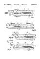
- FIG. 1is a line drawing diagrammatically illustrating in cross-section a single arteriotomy in an occluded superficial femoral artery of a medical patient;
- FIG. 2Ais a line drawing schematically illustrating in cross-section a double arteriotomy in an occluded superficial femoral artery of a medical patent;
- FIG. 2Bis a line drawing schematically illustrating in cross-section access using a hollow needle to a site upstream of an atheroma in a superficial femoral artery of a patient;
- FIG. 3is a line drawing diagrammatically illustrating in cross-section the atheroma of FIG. 1 with a guide wire extending through the atheroma;
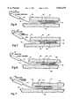
- FIG. 4is a line drawing diagrammatically illustrating in cross-section placement of a dynamic wire guide through the arteriotomy sufficient for the distal region of the dynamic wire guide to extend completely through the atheroma accommodating passage of a guide wire through a lumen in the dynamic wire guide before the dynamic wire guide is withdrawn;
- FIG. 5is a line drawing diagrammatically illustrating in cross-section the advancement of a dynamic disrupter, over a guide wire for traversing the stenotic obstruction site in the superficial femoral artery;
- FIG. 6is a line drawing diagrammatically illustrating in cross-section the advancement of a coring catheter along a guide wire spanning the atheroma obstruction in the artery to enlarge the lumen by removal of plaque;
- FIG. 7is a line drawing diagrammatically illustrating in cross-section the artery showing an expandable cutting catheter or atherotome displaceable along the guide wire and expansion of blades of the cutter so as to cut plaque from the atheroma, using as many passes as appropriate with or without flushing or irrigating of the lumen;
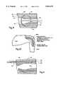
- FIG. 8is a line drawing diagrammatically illustrating in cross-section removal of the tunica horr endothelium and tunica media collectively from an artery at a natural interface of weakness existing between the tunica media and the tunica adventitia;
- FIG. 9is a line drawing diagrammatically illustrating in cross-section separation of a length of the tunica intima endothelium together with the tunica media from the tunica adventitia along a natural interface of weakness using a Hall loop;
- FIG. 10is a line drawing diagrammatically illustrating in cross-section a vascular graft according to the present invention having collapse resistant characteristics placed in the knee of a patient;
- FIG. 11is a line drawing diagrammatically illustrating in fragmentary cross-section use of a Scanlan Endarsector to separate conjointly a length of the tunica intima endothelium and tunica media from the tunica adventitia along a natural interface of weakness;
- FIG. 12is a line drawing diagrammatically in cross-section a Simpson Atherocath performing an atherectomy
- FIG. 13is a line drawing diagrammatically illustrating in cross-section performance of a balloon angioplasty
- FIG. 14is a line drawing diagrammatically illustrating in cross-section the performance of an atherectomy using a laser
- FIG. 15is a line drawing diagrammatically illustrating in cross-section performance in an artery of ultrasound angioplasty
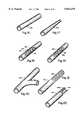
- FIG. 16is a line drawing diagrammatically illustrating in perspective one suitable pre-formed cylindrical or sleeve-shaped vascular graft for lining arteries in accordance with the present invention
- FIG. 17is a line drawing diagrammatically illustrating in perspective a tapered, pre-formed vascular graft for carrying out the present invention.
- FIG. 18is a line drawing diagrammatically illustrating in perspective, with parts broken away for clarity, the utilization of a vascular graft, pre-formed and cylindrical or sleeve-shaped in configuration, having internal ring reinforcements;
- FIG. 19is a line drawing diagrammatically illustrating in perspective, with parts broken away for clarity, a vascular graft, pre-formed and cylindrical or sleeve-shaped in configuration, having internal helically-shaped reinforcement, for carrying out the present invention
- FIG. 20is a line drawing diagrammatically illustrating in perspective a bifurcated vascular graft for carrying out the present invention
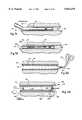
- FIG. 21is a line drawing diagrammatically illustrating in perspective a vascular graft, pre-formed and cylindrical or sleeve-shaped in configuration, having tissue in-growth material along a portion of the exterior surface thereof;
- FIG. 22is a line drawing diagrammatically illustrating in perspective, with a portion broken away for clarity, a vascular graft, pre-formed and cylindrical or sleeve-shaped in configuration, having an expandable stent internally sutured at the distal end thereof in the contracted state, for carrying out the present invention
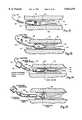
- FIG. 23is a line drawing diagrammatically illustrating in cross-section placement of a dilator/sheath along a guide wire into the artery for placement of a vascular graft;
- FIG. 24is a line drawing diagrammatically illustrating in cross-section the sheath of FIG. 23 with the distal portion thereof in the artery after the dilator has been removed;
- FIG. 25is a line drawing diagrammatically illustrating in elevation a vascular graft placement mandrel having a vascular graft attached to the mandrel shaft for placement in an artery;
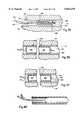
- FIG. 26is a line drawing diagrammatically illustrating in cross-section of the vascular graft and the distal end of the mandrel of FIG. 25 being advanced into the artery through the sheath of FIG. 24;
- FIG. 26Ais a cross-section taken along line 26A--26A of FIG. 26;
- FIG. 27is a line drawing diagrammatically illustrating in cross-section partial removal of the sheath of FIG. 25 after the distal end of the mandrel shaft and the vascular graft has been placed in the desired position in,the artery through the sheath, with the graft being held by the mandrel while the sheath is withdrawn;
- FIG. 28is a line drawing diagrammatically illustrating in cross-section the existence of the vascular graft in the artery after both the sheath and the mandrel have been removed therefrom;
- FIG. 29is a line drawing diagrammatically illustrating in cross-section a balloon catheter disposed in the vascular graft after the graft has been positioned as illustrated in FIG. 28;
- FIG. 30is a line drawing diagrammatically illustrating in cross-section the vascular graft firmly contiguous with the inside surface of the artery after the vascular graft has been expanded by use of the balloon catheter illustrated in FIG. 29 and the balloon catheter but not the guide wire has been removed;
- FIG. 31is a line drawing diagrammatically illustrating in cross-section the disposition of the vascular graft in the artery after all other paraphernalia has been removed;
- FIG. 32is a line drawing diagrammatically illustrating in cross-section the vascular graft of FIG. 32 linearly disposed within and sutured proximally near the wall of the superficial femoral artery;
- FIG. 33is a line drawing diagrammatically illustrating in cross-section grasping of the distal end of a vascular graft in the treated artery using forceps;
- FIG. 34is a line drawing diagrammatically illustrating in cross-section a vascular graft, sutured at the distal end thereof to the distal end of a mandrel both disposed in a treated artery;
- FIG. 35is a line drawing diagrammatically illustrating in cross-section placement of the distal end of a vascular graft in an artery by use of a placer/suturer;
- FIG. 36is a line drawing diagrammatically illustrating in fragmentary cross-section the securing of both ends of a vascular graft in an artery using one or more sutures at each end;
- FIG. 37is a line drawing diagrammatically illustrating in fragmentary cross-section securing of a vascular graft in a treated artery using staples at both the distal and proximal ends of the vascular graft;
- FIG. 38is a line drawing diagrammatically illustrating in cross-section a vascular graft secured at its distal end in an artery using an expanded stent;
- FIG. 39is a line drawing diagrammatically illustrating in cross-section placement of a coating on the treated interior surface of an artery to form in place a vascular graft.
- FIG. 40is a line drawing diagrammatically in cross-section a balloon catheter having the balloon thereof partially inflated within a vascular graft prior to joint insertion into a treated artery;
- FIG. 41is a line drawing diagrammatically in cross-section the partially inflated balloon catheter and vascular graft after placement in a treated artery.
- the illustrated embodimentsdemonstrate and are representative of methods by which a partially or totally occluded artery or other vessel of a patient is recanalized and the risk of restenosis is substantially reduced or eliminated by use of a vascular graft within the treated artery.
- While the present inventionmay be used in a vessel other than an artery, the primary benefit lies in application to an artery.
- Artery flowis either conduit or branch flow.
- the iliac, femoral, and more distal arteriesare most likely to occlude, either totally or partially. All arteries are strong, durable, three-layer vessels while veins are thin, single layer conduits.
- the arterial wall layersare, inside out, the tunica intima endothelium (intima), the tunica media (media), and the tunica adventitia (adventitia). It has been found that in diseased arteries typically the interface between the adventitia layer and the media layer becomes a region of naturally occurring weakness. In fact, it has been found that plaque not only accumulates within the lumen of the artery but infiltrates both the intima and media causing a tissue breakdown there.
- plaque depositsmay form in some arteries and not at all or slightly in other arteries of the same person.
- a plaque deposit in a specific area or region of an arteryis sometimes called an atheroma.
- the arteryUnder appropriate anesthesia the artery is exposed, clamped, and at least a single arteriotomy is performed distal to the clamp and proximal to the occlusion. Under some circumstances two arteriotomies are performed, one upstream and the other downstream of the atheroma although a single arteriotomy is preferred. In some situations access to the artery can be by use of percutaneously placed hollow needle, instead of by use of an arteriotomy.
- a guide wireis advanced through an upstream arteriotomy until the guide wire extends beyond the atheroma.
- a guide wirecan be advanced through a clogged artery, but not always.
- a dynamic wire guide or a dynamic disrupteris preferably used to centrally loosen and/or displace the centrally disposed plaque followed by central insertion of the guide wire through the hollow interior in the dynamic wire guide or disrupter. Thereafter, the dynamic wire guide or disrupter is removed.
- plaqueis severed from the inner wall of the intima.
- plaquemay be so severed by a coring catheter or by using an atherotome having one or more expandable blades to accommodate insertion and one or more passes through the atheroma, each pass at an increased blade diameter.
- Atherectomy devicessuch as a Simpson Atherocath, an Auth Rotablator, a Kensey-device, or an Interventional Technologies Transluminal Extraction Catheter (TEC device) may be used.
- TEC deviceInterventional Technologies Transluminal Extraction Catheter
- an endarterectomyis the preferred medical choice.
- an endarterectomyis often best when the disease of the artery is substantially advanced, causing a natural interface of weakness between the media and the adventitia.
- a cutting atherotomemay be used to initially cut through the diseased intima and media to the adventitia at the distal end of the site of the endarterectomy creating a taper at that location followed by advancement in a proximal direction until the entire undesired length of intima and media have been excavated.
- the intima and mediamay be cut radially or on a bevel adjacent both a first and second arteriotomy located above and below the atheroma.
- a taperis used at both ends of the endarterectomy where the enlarged lumen produced connects across a beveled tapered to the normal lumen of the artery, both distally and proximally the dispensed material is loosened from the wall using any suitable instrument, such as a surgical spatula. Forceps may be used to grasp and pull upon a loosened part of the intima and media to be removed causing the intima and media between the two cuts together with the atheroma contained therein to be removed from the artery as a cylindrical unit.
- a Hall loopmay be advanced from one arteriotomy to the other after the two above-mentioned cuts have been made.
- the loopin the nature of a piano wire loop held on the end of a staff is positioned at the above-mentioned natural interface of weakness.
- the loopis positioned at and displaced along the interface by pushing on the staff until the intima, the media, and the atheroma to be removed have been unitarily severed following which the cylindrical unit may be grasped and removed from the artery using forceps, for example.
- an instrument of expansionis used to enlarge or open and enlarge the blood flow accommodating lumen at the atheroma.
- Mechanical instruments, equipment for performing balloon angioplasty, laser instruments, and instrumentation for ultrasound angioplastymay be used to achieve the angioplasty.
- Vascular graftis intended to mean any of the following: 1. conventional and novel artificial grafts made of any material, including but not limited to fabrics such as dacron, or expanded PTFE GortexTM thin wall sleeve material, in any density from very soft and low density to very stiff and high-density, constructed in any shape including straight, tapered, or bifurcated, and which may or may not be reinforced with rings and spirals or other reinforcement, and which may or may not have one or more expandable stents incorporated into the graft at one or both ends or along its length, 2.
- fabricssuch as dacron, or expanded PTFE GortexTM thin wall sleeve material, in any density from very soft and low density to very stiff and high-density, constructed in any shape including straight, tapered, or bifurcated, and which may or may not be reinforced with rings and spirals or other reinforcement, and which may or may not have one or more expandable stents incorporated into the graft at one or both ends or along its length, 2.
- vascular graftany combination of the foregoing vascular graft options.
- the exterior of the vascular graft or part of itmay and preferably does comprise tissue in-growth material.
- tissue in-growth materialWhere a pre-formed tubular vascular graft of synthetic material is used, the material thereof may be and preferably is dimensionally stable. However, if desired, it may be radially expandable material.
- the vascular graft of choicemay be introduced into the treated artery or other vessel in any suitable way including but not limited to use of a dilator/sheath, placement of the vascular graft upon a mandrel shaft and/or use of long-nose forceps.
- the distal ends of the tubular graft and the mandrel shaftmay be temporarily sutured together or the distal end of the vascular graft sutured together over the mandrel to accommodate unitary displacement into the vessel, for example through a sheath after the dilator has been removed.
- the diametral size of the graftmay be enlarged in contiguous relationship with the inside arterial surface using a balloon catheter.
- a balloon cathetermay also be used to bring a folded or partially collapsed vascular graft which is dimensionally stable into contiguous relation with the interior surface of the remaining artery wall.
- the tubular graftmay also comprise a biologically inert or biologically active anti-stenotic coating applied directly to the treated area of the remaining arterial inner surface to define a lumen of acceptable blood flow capacity.
- the graftonce correctly positioned and contiguous with the interior vascular wall, is usually inherently secure against inadvertent migration within the artery or other vessel due to friction and infiltration of weeping liquid accumulating on the inside artery wall. It is preferred that the length of the vascular graft be selected to span beyond all of the treated region of the artery.
- One or both ends of the vascular graftmay be sutured or surgically stapled in position on the treated wall to prevent undesired displacement or partial or complete collapse under cardiovascular pressure.
- the upstream end of a graft placed in an arterymust be secure to prevent a flap of the graft from being pushed, by arterial blood flow, into a position where it occludes, in whole or in part, the vessel.
- One or both endsmay be held open by one or more stents disposed within the tubular graft. Forceps may be used to hold a free end of the vascular graft while the other end is secured to the vascular wall.
- the proximal end of the tubular vascular graftto the treated vascular wall and to bias dilate the distal end of the tubular vascular graft by use of a balloon catheter and/or arterial pressure.
- the distal exterior of the sleeve-shaped vascular graftcomprises tissue in-growth material, as is preferred as in-growth occurs it becomes immaterial how the initial dilating bias was achieved.
- FIG. 1illustrates the juncture between the common femoral artery and the superficial femoral artery and profunda femoris artery, respectively located at a site near the groin of a medical patient.
- FIG. 1further illustrates the existence of a surgically created arteriotomy 50 providing access to the superficial femoral artery 52 at a location proximal of an atheroma, generally designated 54.
- the atheroma 54comprises a centrally located, relatively soft central plaque portion 56 surrounded by a calcified plaque portion 58.
- FIG. 2Ais similar to FIG. 1 and further illustrates a second arteriotomy 50' located distal of the atheroma 54, providing a second access site to the artery 52, as explained herein in greater detail.
- FIGS. 1, 2A, and 2Billustrate an atheroma which completely occludes the artery 52
- the present inventionapplies to both partial and complete occlusion due to plaque.
- the overall objectiveis to restore substantially full blood flow to the artery and prevent restenosis.
- the artery receiving treatmentis temporarily deprived of blood flow altogether, using known methods of temporary occlusion. Prior to temporary occlusion, systemic or regional heparinization may be effected.
- a guide wire 62is advanced distally through the arteriotomy 50 and through the atheroma 54 along the softer plaque portion 56 thereof.
- the guide wire 62alone cannot be manually caused to traverse the atheroma 54, as illustrated in FIG. 3, other medical instruments may be used to create a passageway through the atheroma 54 following which the guide wire 62 may be appropriately inserted so as to traverse the atheroma 54.
- a dynamic wire guide 64may be advanced and operated so as to create a lumen through the softer plaque 56 of the atheroma 54 as diagrammatically illustrated in FIG. 4.
- the guide wire 62is advanced through the lumen within the dynamic wire guide 64, following which the dynamic wire guide is withdrawn leaving the guide wire 62 in position, as a guide for instruments by which the soft and hard plaque 56 and 58 are removed.
- a dynamic disrupter 66having a rotating enlarged rounded tip 67, may be used in lieu of the dynamic wire guide described above to penetrate the softer plaque region 56 sufficient to accommodate concentric insertion of the guide wire 62 through the dynamic disrupter 66, with the dynamic disrupter 66 after being removed along the guide wire while the guide wire is retained in its inserted position.
- the preferred dynamic disrupteris the one disclosed in pending U.S. patent application Ser. No. 07/973,514, filed Nov. 9, 1992, assigned to EndoVascular Instruments, the assignee of the present application, although other dynamic disrupters could be used.
- FIG. 6illustrates diagrammatically utilization of a coring catheter 70, advanced along the guide wire 62 through the arteriotomy 50 so as to cut the plaque 58 from the artery 52 using as many passes along the atheroma 54 as necessary.
- the coring catheterhas a cutting head 72 which is caused to be rotated by the surgeon. It is currently preferred that the coring catheter 70 be that which is disclosed in the assignee's co-pending U.S. patent application Ser. No. 07/973,514, which was filed Nov. 9, 1992, although any suitable coring catheter may be utilized.
- the lumen across the atheroma 54can be enlarged using an expandable cutter, having diametrally expandable cutting blades as illustrated in FIG. 7.
- the expandable cutter 74is initially advanced along the guide wire 62 in an unexpanded state.
- Expandable cutter 74has a diametrally adjustable cutting head 76 which, when expanded and pulled forward atherectomy 50 will cut or shave the plaque at deposits 58.
- the expandable cuttermay be utilized in a fashion in which the expandable cutting blades, when expanded, engage and grab hold of a section of the plaque.
- FIG. 8illustrates, in part, one way in which the intima 100 and the media 102 are collectively separated from the adventitia 104 along a natural interface of weakness 106, which typically exists in diseased arteries.
- a first and second arteriotomy 50 and 50'may be made proximal and distal of the atheroma and a radial or tapered cut at or near each arteriotomy made through the intima and media layers to the interface 106.
- the loosened partis available for grasping, using a suitable instrument such as forceps 108 illustrated in FIG. 8.
- a suitable instrumentsuch as forceps 108 illustrated in FIG. 8.
- the cut length of intima and mediais severed along interface 106 and pulled from the artery through arteriotomy 50.
- all arteriescomprise three layers, the intima, the media, and the adventitia.
- Atherectomy and endarterectomyare somewhat arbitrary, as it depends upon whether the material being removed consists exclusively of atheroma only, or of a combination of atheroma and material characteristic of the inner lining of the vessel. Pathology analysis of such removed material frequently indicates the presence of cells and other material characteristic of both plaque and the media and intima, so it is probably most correct to refer to this procedure as an endarterectomy.
- the expandable cutteris employed to remove the material that has been loosened. With the blades unexpanded, the expandable cutter is advanced a suitable distance into the atheromatous region, and then the blades expanded. When the expandable cutter is withdrawn, it engages the plaque and arterial lining, and exerts force upon the natural interface of weakness.
- the plaque and arterial liningare withdrawn by the expandable cutter in the form of a cylindrical plug of material, which may be short or long depending upon how far into the plaque the cutter is advanced before it is expanded.
- the bladesAfter removing the plug of material from the cutter, the blades are returned to the unexpanded position and re-advanced into the artery, this time to a position further than the previous advancement, so that a new length of atheromatous material can be engaged.
- the bladesare once again expanded, and a new plug of material is engaged and withdrawn.
- any desired length of arterymay be excavated of its plaque and inner lining.
- the distal tapered shape that the blades assume when expandedleaves behind the desired tapered shape as it cuts and removes the final plug of material from the artery. This eliminates any need to make the second arteriotomy 50', for the purpose of making the distal radial cut, when the expandable cutter is employed.
- an endarterectomymay be performed using a Hall loop, as diagrammatically illustrated in FIG. 9.
- the artery containing the atheroma 54is accessed, as illustrated in FIG. 2A, by first and second arteriotomies 50 and 50'.
- the first radial or beveled cut through the intima and mediais made, as described above, and the media is severed along interface 106 at one end or the other (usually the upstream, proximal end) for a short distance to allow the loop 110 to be placed at the interface, with the flexible shaft 112 extending in the direction of the pull and through the more remote arteriotomy.
- the loopWhen power is applied, the loop is caused to oscillate as the Hall loop is advanced along the interface 106 until complete severance has occurred, following which forceps may be used to pull the removed intima and media layers from the artery through the proximal arteriotomy after the second radial or beveled cut through the intima and media is made, attempting to leave a tapered contour to the remaining material at the distal end of the endarterectomy.
- the Hall loopis more fully described in U.S. Pat. No. 3,730,185.
- the endarterectomymay similarly be performed using a Scanlan Endarsector, as generally illustrated in FIG. 11.
- the Scanlan Endarsector 114is a commercially available instrument, sold by Scanlan International, Inc., 1 Scanlan Plaza, St. Paul, Minn. 55107, and may be used alone or in conjunction with other instruments to perform the endarterectomy.
- the Scanlan Endarsector 114comprises a handle (not shown) from which an elongated U-shaped shaft extends.
- FIGS. 12 through 15illustrate various ways in which an atherectomy may be performed when that procedure is the treatment of choice, in whole or in part, for enlarging the blood flow lumen of artery 52 at atheroma site 54.
- the atherocathcomprises an outside, hollow shaft 118 through which extends a rotatable inner shaft 120 to which a rotating cutter head 122 is non-rotatably attached.
- the rotating cutting head 122cuts plaque 58 from the interior of the artery 52 as the atherocath is advanced.
- a balloon 124is inflated on the side opposite the cutting head 122 to thereby bring pressure to bear against the artery and urge the cutting head firmly against the plaque.
- a chamber 126At the distal end of the atherocath is located a chamber 126, which functions to collect plaque shavings removed by the cutting head 122.
- the atherocath 116is inserted and removed along guide wire 62.
- the Simpson Atherocathis commercially available from Devices for Vascular Intervention, division of Eli Lilly, 26201 YNEZ Road, Temecula, Calif. 92591.
- FIG. 13diagrammatically represents the use of balloon angioplasty to enlarge the lumen of an atheroma-ridden artery.
- a balloon 302 of a balloon catheter 300is advanced along guide wire 62 until it is disposed within the atheroma 54.
- the balloon 302is expanded, which radially expands the plaque 58. This process ordinarily creates cracks in the plaque, but nevertheless results in an enlarged lumen through the plaque 58 although, typically, the plaque 58 is not intentionally removed.
- FIG. 14diagrammatically illustrates use of a laser instrument, generally designated 130 to remove plaque 58 from artery 52.
- the laser instrument 50comprises a source 132 of laser energy. The laser energy is processed along a bundle of optical fibers disposed within a catheter 134. Laser beams 136 are emitted from the instrument 130 through a plurality of laser emitters 138. The laser beams 136 cut plaque from deposits 58 as the distal end of the catheter 134 is advanced distally into the plaque 58.
- the laser instrument 130is illustrated as being concentrically disposed upon guide wire 62 for insertion, advancement, and ultimate removal. Thus, an atherectomy may be performed in accordance with the principles of the present invention by use of one or more laser beams.
- a suitable laser instrumentis the Laserprobe PLR or Lasercath-PRL, used with the Optilase Laser Source System, all of which are available from Trimedyne, Inc., 1815 East Carnegie Avenue, Santa Ana, Calif. 92705.
- FIG. 15illustrates diagrammatically an ultrasound instrument, generally designated 140.
- Instrument 140comprises a source of ultrasound energy, i.e., ultrasound transducer 142.
- Transducer 142connects via an ultrasound shaft 144 to an ultrasound head 146.
- the ultrasound shaft 144is substantially concentrically disposed within an ultrasound catheter 148.
- a guide wireis not used. Release of ultrasound energy from head 146 is caused to impinge upon plaque 58 fracturing the same progressively, thereby enlarging the blood flow lumen of the artery 52.
- a suitable ultrasound instrument for removal of plaqueis the Sonocath, available from Angiosonics, Wayne, N.J. (201) 305-1770.
- the materialmay be dimensionally stable or capable of being expanded, for example, using a balloon catheter and/or one or more stents.
- vascular graft 200(FIG. 16) may be used.
- Vascular graft 200is illustrated as having blunt ends, is cut to a length commensurate with the treated artery and comprises exterior and interior surfaces respectively comprising a uniform diameter along the entire length of the vascular graft 200.
- the wall thicknessis also illustrated as being uniform.
- tapered vascular graft 202may be preferable, the degree of taper being selected so as to match the taper of the artery subjected to one or more of the treatments described above.
- vascular graft 204may be used, the configuration thereof being adapted to conform specifically to the nature of the shape, size, and disposition of the branched artery subjected to treatment.
- vascular graft 204may be straight or tapered or straight in part and tapered in part.
- the vascular graftmay be reinforced, particularly when no expansion thereof is required during placement.
- Two typical forms of reinforcementare illustrated in FIGS. 18 and 19, respectively, which depict vascular graft 206 and vascular graft 208, respectively.
- Vascular graft 206comprises reinforcement in the form of a plurality of rings 210. While illustrated as being embedded within the material 212 from which the vascular graft 206 is formed, the reinforcing rings could be placed either internally or externally in respect to the graft 206 itself.
- vascular graft 208is illustrated in FIG. 19 as comprising a continuous, helical reinforcement 214 embedded in the material 216 from which the vascular graft 208 is formed.
- the reinforcement 214could be placed as well either internally or externally of the vascular graft 208 itself.
- the reinforcemente.g., rings 210 and helix 24 can be of any suitable biologically inert material such as an implantable grade of thermoplastic material, e.g., polypropylene or nylon.
- tissue in-growth materialat the exterior of all or part of the vascular graft may be desirable.
- FIG. 21diagrammatically illustrates the existence of tissue in-growth material 220 disposed along approximately the distal one-half of the hollow cylindrically-shaped vascular graft 222.
- the value of the tissue in-growth materialis that it becomes, in due course of time, the primary connector between the treated arterial surface and the vascular graft.
- FIG. 22there is diagrammatically illustrated a hollow cylindrical vascular graft 224 to which an expandable stent 226 has been connected interiorly at the proximal end thereof using sutures 228.
- the stent 226is conventionally expanded to bias the proximal end of the vascular graft 224 contiguously against the treated arterial surface to retain the position of placement. This condition is illustrated in FIG. 38. While illustrated as being placed internally inside of graft 224, the stent could also be placed externally or it could be embedded within the material from which the vascular graft 224 is formed.
- Utilization of a vascular graft within the context of the present inventionsignificantly tends to provide a barrier between the bloodstream and the vessel wall which is believed to reduce restenosis, provides a conduit through which the blood can flow which is known to be well-tolerated by the bloodstream, preserves the area available for blood flow, prevents an aneurysm, promotes rapid healing without excessive weeping or adhesion of blood at the lining site between the vascular graft and the adventitia layer, and provokes minimal scarring. Plaque, it has been determined, does not form on and adhere to the vascular graft.
- the treated arterial walle.g., at interface 106
- the treated arterial wallmay be lined using a liquid coating of suitable material applied as a spray or otherwise and allowed to cure until a hollow lumen is defined within the cured coating and the treated arterial surface is concealed by toe coating, or allowed to remain in place long enough to cause the artery to form a stable, hollow lumen.
- FIG. 39illustrates the presence of a manually controlled nozzle 230 forming a part of a surgical spraying instrument by which a coating 232 is applied to the treated arterial surface at interface 106.
- Suitable coatingsfor example, having the requisite biologically inert characteristics and wall adherence characteristics would include pharmaceutical-grade collagen available from Collagen Corp., 1850 Embariadero Road, Palo Alto, Calif. 94303.
- vascular graft of choicehas been selected, other than an in-place coating, insertion of the vascular graft into the treated artery must be achieved. It is currently preferred to use a commercially available dilator/peel-away sheath generally designated 250 (FIGS. 23, 24, 26, and 27). However, a solid (non-peel-away) sheath may also be utilized or the graft may be inserted directly into the vessel without use of a sheath. As is well known in the art, the dilator/sheath 250, in assembled condition, is passed concentrically along the guide wire 62 through the access opening to the artery 52.
- the access openingmay be an arteriotomy 50 or a percutaneous venipuncture caused by insertion of needle 60 (FIG. 2B) followed by advancement of the guide wire through the needle 60 and subsequent removal of the needle.
- the dilator 252 at the tapered distal tip 254enlarges the radial size of the puncture as does the sheath 256 (slightly) as the dilator-sheath 250 is advanced through the puncture concentrically around the guide wire 62 until the dilator-sheath 250 is positioned as illustrated in FIG. 23.
- the medical attendantsimply manually retracts the dilator along the guide wire 62 until it is fully removed, leaving the sheath 256 in place with the proximal end thereof exposed, as diagrammatically illustrated in FIG. 24.
- stepsare taken to insert the vascular graft through the sheath and locate the graft in the treated artery so as to be, preferably, at least co-extensive with the treated artery surface, with the guide wire inside the graft.
- the treated artery surface shown in FIGS. 23-24 and 26-27is interface 106.
- One way in which insertion may be consummatedis by use of a graft placement long-nose forceps, generally designated 260 (FIG. 25) which comprises a control handle 262 from which a mandrel shaft 264 distally extends.
- Activation of the control 262causes bifurcated tips 266 located at the distal end of the mandrel shaft 264 to open and close, to grasp or clamp and release, respectively, the distal end 268 of a hollow tubular vascular graft 270.
- tips 266located at the distal end of the mandrel shaft 264 to open and close, to grasp or clamp and release, respectively, the distal end 268 of a hollow tubular vascular graft 270.
- the vascular graftfollows the mandrel shaft 264 as it is advanced over the guide wire 62 and through the sheath 256 as illustrated in FIGS. 26 and 27.
- the forceps 260 and graft 270are held in a stationary position, the forceps grasping the graft, as the sheath is withdrawn.
- peel-away sheath 256as the sheath is withdrawn it is manually split into two pieces, as illustrated in FIG. 27, following which each piece is discarded.
- the sheathmay be placed correctly in the artery 52 using a hollow mandrel, generally designated 280 (FIG. 34).
- the sheath 270is concentrically disposed around the hollow mandrel 280 with the distal ends of each being sutured together using apertures 282 located in the distal end of the mandrel 280.
- a suture 284helically through the apertures 282 and through the adjacent thickness of the vascular graft 270, the vascular graft and the mandrel are secured together.
- the suture 284may be extended through the hollow of the mandrel 280 and through the arteriotomy 50 for access by the medical attendant.
- one end of the suture 284is pulled by the medical attendant, causing the suture to helically unwind at the distal end of the vascular graft 270 for complete removal of the suture 284, following which the mandrel 280 is fully retracted leaving the vascular graft 270 correctly disposed in the artery 52, with the guide wire 62 inside the graft.
- an elongated, long-nose forceps 290may be used as well for correct placement of the vascular graft 270.
- Long-nose forceps 290may be of any suitable type, such as commercially available pediatric bronchoscopy forceps or retrieval forceps, such as Storz's. More specifically, the forceps 290 comprise exposed jaws 292 which are controlled at the proximal end of the forceps 290 accommodating opening and closing of the jaws 292.
- the vascular graft 270is now correctly located in the artery 52, with the guide wire 62 passing through the center of the vascular graft 270, as illustrated in FIG. 28.
- Insertion of a tubular graft of choice into the treated arteryoften involves folding or other forms of reduction in the diametral size occupied by the vascular graft during insertion, for example, to accommodate a size which will allow displacement through the sheath 256.
- the sheath handlemay accept a graft folded shown in FIG. 26A. This folded configuration may continue the length of the sheath, to allow the easier passage of the graft through the sheath, by de-forming the inside diameter to the shape, or by laying a conventional catheter or wire alongside the graft during insertion to create an indentation in the graft.
- the vascular graftif left alone, tends to be and remain non-contiguous with the treated surface at the interior of the artery, e.g., surface 106, e.g., retaining the crimped or folded shape it assumes during insertion.
- a balloon catheter 300 of conventional, commercially available designbe advanced concentrically around the guide wire 62 until the balloon 302 thereof is positioned within the sheath 270 just inside the distal edge 268' of the sheath 270. See FIG. 29.
- the vascular graft 270is caused to become contiguous with and adhered to the adjacent arterial wall surface, following which the balloon 302 is deflated and the balloon catheter 300 retracted along the guide wire and discarded, leaving the vascular graft 270 postured as illustrated in FIG. 30.
- one very long balloon cathetercan be employed to perform this step in a single balloon expansion, and/or the balloon can be sized to exactly match the graft, e.g., tapered balloon used with tapered graft, etc.
- tubular vascular graft 270positioned as essentially illustrated in FIG. 31. It has been found that once the tubular vascular graft is firmly contiguous with the adjacent arterial wall surface, a measure of friction exists which both prevents radial collapse and axial displacement of the vascular graft within the artery. In addition, the treated arterial surface tends to weep slightly which weeping adheres to the exterior surface of the tubular graft and tends to infiltrate the material from which the tubular graft is formed at least to a limited extent further causing the graft to be retained in its expanded stationary position, fully dilated within the artery.
- proximal end 269 of the vascular graft 270be physically connected to the adjacent arterial wall, in this case adventitia layer 104, and that the distal end 268 be left to natural adherence, with the arterial blood pressure holding the distal end 268 in its fully dilated position together with friction at the surface 106 and tissue infiltration into the material from which the graft 270 is fabricated.
- the utilization of one or more sutures 304is illustrated as the structure by which the proximal end 269 of the vascular graft 270 is physically secured to the arterial wall.
- the graftOver the longer term, the graft will be held open and contiguous with the remaining original wall of the artery throughout its length by arterial blood pressure and, in grafts so constructed, by tissue in-growth into the tissue in-growth material.
- This particular feature of intra-luminal graft placementsolves a specific problem of by-pass graft placement where by-pass grafts have previously been placed in tissue tunnels constructed to by-pass the original duct or vessel lumen. Many such grafts are placed in body regions where, under normal activities, the body tends to compress grafts and thereby cut off flow through such grafts when they are placed in tissue tunnels which by-pass the original lumen.
- the example of the human knee jointis illustrated in FIG. 10.
- FIG. 10An improved result is obtained using the intra-luminal graft placement described herein is illustrated in FIG. 10.
- the original artery lumenremains open and patent in the knee even when the knee is bent. More generally, ducts and vessels naturally remain open and patent during the normal range of activities.
- the lumen of the graftwhich is adhering to the remaining original wall of the artery by tissue in-growth and/or due to the arterial pressure inside the graft, is illustrated as remaining open and patent even while the knee is bent. More generally, intra-luminal grafts held in place in vessels or ducts by tissue in-growth will remain open and patent during the normal range of activities, including activities that tend to obstruct by-pass grafts placed in tissue tunnels.
- FIG. 36illustrates utilization of one or more sutures 304 to secure both the proximal and distal ends 269 and 268, respectively, of the vascular graft 270 to the arterial wall 104. Placement of sutures 304 at the distal end 268 of the vascular graft 270 would ordinarily require a second, downstream arteriotomy.
- vascular graft 270may be secured to the arterial wall 104 using medical grade staples 306, as illustrated in FIG. 37.
- either or both ends of the vascular graft 270can be expanded and held in contiguous relationship with arterial surface 106 using one or more stents 226, as explained above and as illustrated in FIG. 38.
- the distal end 268 of the vascular graft 270may be grasped using suitable forceps 310 for both positioning the vascular graft 270 and for holding it in position while, for example, the proximal end of the graft is suitably fastened to the arterial wall as explained above. See FIG. 33.
Landscapes
- Health & Medical Sciences (AREA)
- Life Sciences & Earth Sciences (AREA)
- Engineering & Computer Science (AREA)
- Biomedical Technology (AREA)
- Public Health (AREA)
- Veterinary Medicine (AREA)
- Heart & Thoracic Surgery (AREA)
- Vascular Medicine (AREA)
- Animal Behavior & Ethology (AREA)
- General Health & Medical Sciences (AREA)
- Surgery (AREA)
- Transplantation (AREA)
- Oral & Maxillofacial Surgery (AREA)
- Cardiology (AREA)
- Nuclear Medicine, Radiotherapy & Molecular Imaging (AREA)
- Medical Informatics (AREA)
- Molecular Biology (AREA)
- Gastroenterology & Hepatology (AREA)
- Pulmonology (AREA)
- Surgical Instruments (AREA)
- Media Introduction/Drainage Providing Device (AREA)
Abstract
Description
Claims (12)
Priority Applications (1)
| Application Number | Priority Date | Filing Date | Title |
|---|---|---|---|
| US08/730,421US5842479A (en) | 1993-06-07 | 1996-10-15 | Method of restoring reduced or absent blood flow capacity |
Applications Claiming Priority (3)
| Application Number | Priority Date | Filing Date | Title |
|---|---|---|---|
| US08/073,002US5571169A (en) | 1993-06-07 | 1993-06-07 | Anti-stenotic method and product for occluded and partially occluded arteries |
| US08/402,795US5622188A (en) | 1989-08-18 | 1995-03-13 | Method of restoring reduced or absent blood flow capacity in an artery |
| US08/730,421US5842479A (en) | 1993-06-07 | 1996-10-15 | Method of restoring reduced or absent blood flow capacity |
Related Parent Applications (1)
| Application Number | Title | Priority Date | Filing Date |
|---|---|---|---|
| US08/402,795ContinuationUS5622188A (en) | 1989-08-18 | 1995-03-13 | Method of restoring reduced or absent blood flow capacity in an artery |
Publications (1)
| Publication Number | Publication Date |
|---|---|
| US5842479Atrue US5842479A (en) | 1998-12-01 |
Family
ID=22111093
Family Applications (12)
| Application Number | Title | Priority Date | Filing Date |
|---|---|---|---|
| US08/073,002Expired - LifetimeUS5571169A (en) | 1989-08-18 | 1993-06-07 | Anti-stenotic method and product for occluded and partially occluded arteries |
| US08/698,981Expired - Fee RelatedUS5782847A (en) | 1993-06-07 | 1996-08-16 | Anti-stenotic method for occluded and partially occluded arteries |
| US08/730,420Expired - Fee RelatedUS5836316A (en) | 1993-06-07 | 1996-10-15 | Method of restoring reduced or absent blood flow capacity |
| US08/730,421Expired - Fee RelatedUS5842479A (en) | 1993-06-07 | 1996-10-15 | Method of restoring reduced or absent blood flow capacity |
| US08/731,786Expired - Fee RelatedUS5843165A (en) | 1993-06-07 | 1996-10-18 | Method for increasing blood flow in vessels |
| US08/857,223Expired - Fee RelatedUS5873905A (en) | 1993-06-07 | 1997-05-16 | Anti-stenotic method and product for occluded and partially occluded arteries |
| US08/857,224Expired - Fee RelatedUS5824057A (en) | 1993-06-07 | 1997-05-16 | Anti-stenotic method and product for occluded and partially occluded arteries |
| US09/098,912Expired - Fee RelatedUS5904146A (en) | 1993-06-07 | 1998-03-05 | Anti-stenotic method and product for occluded and partially occluded arteries |
| US09/183,896Expired - Fee RelatedUS6090135A (en) | 1993-06-07 | 1998-10-30 | Anti-stenotic method and product for occluded and partially occluded arteries |
| US09/938,882AbandonedUS20020004680A1 (en) | 1993-06-07 | 2001-08-24 | Anti-stenotic method and product for occluded and partially occluded arteries |
| US11/247,571AbandonedUS20060089706A1 (en) | 1993-06-07 | 2005-10-11 | Anti-stenotic method and product for occluded and partially occluded arteries |
| US11/818,715AbandonedUS20070260215A1 (en) | 1993-06-07 | 2007-06-14 | Anti-stenotic method and product for occluded and partially occluded arteries |
Family Applications Before (3)
| Application Number | Title | Priority Date | Filing Date |
|---|---|---|---|
| US08/073,002Expired - LifetimeUS5571169A (en) | 1989-08-18 | 1993-06-07 | Anti-stenotic method and product for occluded and partially occluded arteries |
| US08/698,981Expired - Fee RelatedUS5782847A (en) | 1993-06-07 | 1996-08-16 | Anti-stenotic method for occluded and partially occluded arteries |
| US08/730,420Expired - Fee RelatedUS5836316A (en) | 1993-06-07 | 1996-10-15 | Method of restoring reduced or absent blood flow capacity |
Family Applications After (8)
| Application Number | Title | Priority Date | Filing Date |
|---|---|---|---|
| US08/731,786Expired - Fee RelatedUS5843165A (en) | 1993-06-07 | 1996-10-18 | Method for increasing blood flow in vessels |
| US08/857,223Expired - Fee RelatedUS5873905A (en) | 1993-06-07 | 1997-05-16 | Anti-stenotic method and product for occluded and partially occluded arteries |
| US08/857,224Expired - Fee RelatedUS5824057A (en) | 1993-06-07 | 1997-05-16 | Anti-stenotic method and product for occluded and partially occluded arteries |
| US09/098,912Expired - Fee RelatedUS5904146A (en) | 1993-06-07 | 1998-03-05 | Anti-stenotic method and product for occluded and partially occluded arteries |
| US09/183,896Expired - Fee RelatedUS6090135A (en) | 1993-06-07 | 1998-10-30 | Anti-stenotic method and product for occluded and partially occluded arteries |
| US09/938,882AbandonedUS20020004680A1 (en) | 1993-06-07 | 2001-08-24 | Anti-stenotic method and product for occluded and partially occluded arteries |
| US11/247,571AbandonedUS20060089706A1 (en) | 1993-06-07 | 2005-10-11 | Anti-stenotic method and product for occluded and partially occluded arteries |
| US11/818,715AbandonedUS20070260215A1 (en) | 1993-06-07 | 2007-06-14 | Anti-stenotic method and product for occluded and partially occluded arteries |
Country Status (1)
| Country | Link |
|---|---|
| US (12) | US5571169A (en) |
Cited By (9)
| Publication number | Priority date | Publication date | Assignee | Title |
|---|---|---|---|---|
| US6090135A (en) | 1993-06-07 | 2000-07-18 | Endovascular Instruments, Inc. | Anti-stenotic method and product for occluded and partially occluded arteries |
| US6096054A (en)* | 1998-03-05 | 2000-08-01 | Scimed Life Systems, Inc. | Expandable atherectomy burr and method of ablating an occlusion from a patient's blood vessel |
| US6183487B1 (en) | 1997-03-06 | 2001-02-06 | Scimed Life Systems, Inc. | Ablation device for reducing damage to vessels and/or in-vivo stents |
| US6451037B1 (en) | 2000-11-22 | 2002-09-17 | Scimed Life Systems, Inc. | Expandable atherectomy burr with metal reinforcement |
| US6500186B2 (en) | 2001-04-17 | 2002-12-31 | Scimed Life Systems, Inc. | In-stent ablative tool |
| US6800083B2 (en) | 2001-04-09 | 2004-10-05 | Scimed Life Systems, Inc. | Compressible atherectomy burr |
| US7179269B2 (en) | 2002-05-20 | 2007-02-20 | Scimed Life Systems, Inc. | Apparatus and system for removing an obstruction from a lumen |
| US20110230818A1 (en)* | 2004-06-23 | 2011-09-22 | Boston Scientific Scimed, Inc. | Cutting balloon and process |
| US11839398B2 (en) | 2016-09-09 | 2023-12-12 | Endovascular Instruments, Inc. | Adjustable ring stripper for more efficiently and effectively removing plaque from arteries |
Families Citing this family (154)
| Publication number | Priority date | Publication date | Assignee | Title |
|---|---|---|---|---|
| US5622188A (en) | 1989-08-18 | 1997-04-22 | Endovascular Instruments, Inc. | Method of restoring reduced or absent blood flow capacity in an artery |
| US6179824B1 (en) | 1993-05-10 | 2001-01-30 | Arthrocare Corporation | System and methods for electrosurgical restenosis of body lumens |
| US5683366A (en) | 1992-01-07 | 1997-11-04 | Arthrocare Corporation | System and method for electrosurgical tissue canalization |
| US6915806B2 (en) | 1993-05-10 | 2005-07-12 | Arthrocare Corporation | Method for harvesting graft vessel |
| US6331188B1 (en) | 1994-08-31 | 2001-12-18 | Gore Enterprise Holdings, Inc. | Exterior supported self-expanding stent-graft |
| US6015429A (en) | 1994-09-08 | 2000-01-18 | Gore Enterprise Holdings, Inc. | Procedures for introducing stents and stent-grafts |
| US5755770A (en)* | 1995-01-31 | 1998-05-26 | Boston Scientific Corporatiion | Endovascular aortic graft |
| EP0950385A3 (en) | 1995-12-14 | 1999-10-27 | Prograft Medical, Inc. | Stent-graft deployment apparatus and method |
| US6042605A (en) | 1995-12-14 | 2000-03-28 | Gore Enterprose Holdings, Inc. | Kink resistant stent-graft |
| CA2245897C (en)* | 1996-02-28 | 2004-12-14 | Impra, Inc. | Flanged graft for end-to-side anastomosis |
| US6273912B1 (en)* | 1996-02-28 | 2001-08-14 | Impra, Inc. | Flanged graft for end-to-side anastomosis |
| US6544276B1 (en) | 1996-05-20 | 2003-04-08 | Medtronic Ave. Inc. | Exchange method for emboli containment |
| US6022336A (en)* | 1996-05-20 | 2000-02-08 | Percusurge, Inc. | Catheter system for emboli containment |
| EP0952795B1 (en) | 1996-11-15 | 2007-01-03 | Cook Incorporated | Splittable sleeve, stent deployment device |
| US6010529A (en)* | 1996-12-03 | 2000-01-04 | Atrium Medical Corporation | Expandable shielded vessel support |
| US5925074A (en)* | 1996-12-03 | 1999-07-20 | Atrium Medical Corporation | Vascular endoprosthesis and method |
| US6551350B1 (en) | 1996-12-23 | 2003-04-22 | Gore Enterprise Holdings, Inc. | Kink resistant bifurcated prosthesis |
| US6352561B1 (en) | 1996-12-23 | 2002-03-05 | W. L. Gore & Associates | Implant deployment apparatus |
| US5827310A (en)* | 1997-01-14 | 1998-10-27 | Endovascular Systems, Inc. | Apparatus for forming custom length grafts after endoluminal insertion |
| GB9709967D0 (en)* | 1997-05-17 | 1997-07-09 | Harris Peter L | Prosthetic grafts |
| JP3391466B2 (en) | 1997-06-13 | 2003-03-31 | アースロケア コーポレイション | Electrosurgical catheter system and catheter for recanalization of occluded body lumen |
| US6855143B2 (en) | 1997-06-13 | 2005-02-15 | Arthrocare Corporation | Electrosurgical systems and methods for recanalization of occluded body lumens |
| JP2002508209A (en)* | 1997-12-15 | 2002-03-19 | プロリフィックス メディカル, インコーポレイテッド | Vascular stent for reduction of restenosis |
| US6651670B2 (en) | 1998-02-13 | 2003-11-25 | Ventrica, Inc. | Delivering a conduit into a heart wall to place a coronary vessel in communication with a heart chamber and removing tissue from the vessel or heart wall to facilitate such communication |
| US20020144696A1 (en) | 1998-02-13 | 2002-10-10 | A. Adam Sharkawy | Conduits for use in placing a target vessel in fluid communication with a source of blood |
| US6808498B2 (en) | 1998-02-13 | 2004-10-26 | Ventrica, Inc. | Placing a guide member into a heart chamber through a coronary vessel and delivering devices for placing the coronary vessel in communication with the heart chamber |
| WO1999040868A1 (en)* | 1998-02-13 | 1999-08-19 | Ventrica, Inc. | Methods and devices providing transmyocardial blood flow to the arterial vascular system of the heart |
| US6139543A (en) | 1998-07-22 | 2000-10-31 | Endovasix, Inc. | Flow apparatus for the disruption of occlusions |
| US6440124B1 (en) | 1998-07-22 | 2002-08-27 | Endovasix, Inc. | Flexible flow apparatus and method for the disruption of occlusions |
| US6210400B1 (en)* | 1998-07-22 | 2001-04-03 | Endovasix, Inc. | Flexible flow apparatus and method for the disruption of occlusions |
| US6093194A (en)* | 1998-09-14 | 2000-07-25 | Endocare, Inc. | Insertion device for stents and methods for use |
| US20050171594A1 (en)* | 1998-12-31 | 2005-08-04 | Angiotech International Ag | Stent grafts with bioactive coatings |
| US7578828B2 (en) | 1999-01-15 | 2009-08-25 | Medtronic, Inc. | Methods and devices for placing a conduit in fluid communication with a target vessel |
| US7025773B2 (en) | 1999-01-15 | 2006-04-11 | Medtronic, Inc. | Methods and devices for placing a conduit in fluid communication with a target vessel |
| CA2360587A1 (en) | 1999-01-15 | 2000-07-20 | Darin C. Gittings | Methods and devices for forming vascular anastomoses |
| US8034100B2 (en) | 1999-03-11 | 2011-10-11 | Endologix, Inc. | Graft deployment system |
| US6261316B1 (en) | 1999-03-11 | 2001-07-17 | Endologix, Inc. | Single puncture bifurcation graft deployment system |
| US7778688B2 (en)* | 1999-05-18 | 2010-08-17 | MediGuide, Ltd. | System and method for delivering a stent to a selected position within a lumen |
| US9572519B2 (en) | 1999-05-18 | 2017-02-21 | Mediguide Ltd. | Method and apparatus for invasive device tracking using organ timing signal generated from MPS sensors |
| US9833167B2 (en)* | 1999-05-18 | 2017-12-05 | Mediguide Ltd. | Method and system for superimposing virtual anatomical landmarks on an image |
| US7285235B2 (en)* | 1999-05-19 | 2007-10-23 | Medtronic, Inc. | Manufacturing conduits for use in placing a target vessel in fluid communication with a source of blood |
| US6635214B2 (en) | 1999-09-10 | 2003-10-21 | Ventrica, Inc. | Manufacturing conduits for use in placing a target vessel in fluid communication with a source of blood |
| US6241745B1 (en) | 1999-09-16 | 2001-06-05 | David Rosenthal | Apparatus and method for performing an endarterectomy |
| WO2001026562A1 (en)* | 1999-10-08 | 2001-04-19 | The General Hospital Corporation D/B/A Massachusetts General Hospital | Percutaneous stent graft and method for vascular bypass |
| US6383171B1 (en) | 1999-10-12 | 2002-05-07 | Allan Will | Methods and devices for protecting a passageway in a body when advancing devices through the passageway |
| US6579299B2 (en)* | 2000-01-31 | 2003-06-17 | Rex Medical, L.P. | Atherectomy device |
| US6572630B1 (en)* | 2000-01-31 | 2003-06-03 | Rex Medical, L.P | Atherectomy device |
| US6419659B1 (en)* | 2000-02-10 | 2002-07-16 | Medventure Technology Corp | Lipid pool aspiration arrangement for the treatment of vulnerable atherosclerosis plaque |
| US6676698B2 (en)* | 2000-06-26 | 2004-01-13 | Rex Medicol, L.P. | Vascular device with valve for approximating vessel wall |
| US6808533B1 (en) | 2000-07-28 | 2004-10-26 | Atrium Medical Corporation | Covered stent and method of covering a stent |
| US6589273B1 (en)* | 2000-10-02 | 2003-07-08 | Impra, Inc. | Apparatus and method for relining a blood vessel |
| US6506178B1 (en)* | 2000-11-10 | 2003-01-14 | Vascular Architects, Inc. | Apparatus and method for crossing a position along a tubular body structure |
| US6682542B2 (en)* | 2000-12-12 | 2004-01-27 | William W. Harkrider | Endoluminal knife |
| US6641607B1 (en) | 2000-12-29 | 2003-11-04 | Advanced Cardiovascular Systems, Inc. | Double tube stent |
| US20080109030A1 (en) | 2001-04-24 | 2008-05-08 | Houser Russell A | Arteriotomy closure devices and techniques |
| US8992567B1 (en) | 2001-04-24 | 2015-03-31 | Cardiovascular Technologies Inc. | Compressible, deformable, or deflectable tissue closure devices and method of manufacture |
| US6695804B2 (en) | 2001-04-24 | 2004-02-24 | Charles Dennis Rugenstein | Device for removal of fatty debris from blood |
| US8961541B2 (en) | 2007-12-03 | 2015-02-24 | Cardio Vascular Technologies Inc. | Vascular closure devices, systems, and methods of use |
| US20020173838A1 (en)* | 2001-05-18 | 2002-11-21 | Frazier O. Howard | Method and apparatus for surgically restoring coronary blood vessels |
| US7201940B1 (en) | 2001-06-12 | 2007-04-10 | Advanced Cardiovascular Systems, Inc. | Method and apparatus for thermal spray processing of medical devices |
| US7144381B2 (en)* | 2001-06-20 | 2006-12-05 | The Regents Of The University Of California | Hemodialysis system and method |
| US6632231B2 (en)* | 2001-08-23 | 2003-10-14 | Scimed Life Systems, Inc. | Segmented balloon catheter blade |
| US20030055486A1 (en)* | 2001-09-19 | 2003-03-20 | Adams John M. | Vascular reinforcement device and method |
| US20030077310A1 (en) | 2001-10-22 | 2003-04-24 | Chandrashekhar Pathak | Stent coatings containing HMG-CoA reductase inhibitors |
| US6979319B2 (en)* | 2001-12-31 | 2005-12-27 | Cardiac Pacemakers, Inc. | Telescoping guide catheter with peel-away outer sheath |
| US6669624B2 (en) | 2002-03-26 | 2003-12-30 | O. Howard Frazier | Temporary heart-assist system |
| US20030225439A1 (en)* | 2002-05-31 | 2003-12-04 | Cook Alonzo D. | Implantable product with improved aqueous interface characteristics and method for making and using same |
| US20030236565A1 (en)* | 2002-06-21 | 2003-12-25 | Dimatteo Kristian | Implantable prosthesis |
| US20040015224A1 (en)* | 2002-07-22 | 2004-01-22 | Armstrong Joseph R. | Endoluminal expansion system |
| US7037319B2 (en)* | 2002-10-15 | 2006-05-02 | Scimed Life Systems, Inc. | Nanotube paper-based medical device |
| US20040220604A1 (en)* | 2003-04-30 | 2004-11-04 | Fogarty Thomas J. | Tissue separation apparatus and method |
| US9861346B2 (en) | 2003-07-14 | 2018-01-09 | W. L. Gore & Associates, Inc. | Patent foramen ovale (PFO) closure device with linearly elongating petals |
| US7799043B2 (en)* | 2003-12-01 | 2010-09-21 | Boston Scientific Scimed, Inc. | Cutting balloon having sheathed incising elements |
| US7338463B2 (en)* | 2003-12-19 | 2008-03-04 | Boston Scientific Scimed, Inc. | Balloon blade sheath |
| US7413558B2 (en)* | 2003-12-19 | 2008-08-19 | Boston Scientific Scimed, Inc. | Elastically distensible folding member |
| US20050182387A1 (en)* | 2004-02-13 | 2005-08-18 | Cardiac Pacemakers, Inc. | Peel-away catheter shaft |
| US20050267520A1 (en) | 2004-05-12 | 2005-12-01 | Modesitt D B | Access and closure device and method |
| US7678133B2 (en) | 2004-07-10 | 2010-03-16 | Arstasis, Inc. | Biological tissue closure device and method |
| US8048144B2 (en)* | 2004-11-30 | 2011-11-01 | Scimed Life Systems, Inc. | Prosthesis fixation device and method |
| CN103190942A (en) | 2005-05-12 | 2013-07-10 | 阿尔斯塔西斯公司 | Access and closure device and method |
| US8709069B2 (en) | 2005-07-01 | 2014-04-29 | C. R. Bard, Inc. | Flanged graft with trim lines |
| WO2007022050A1 (en)* | 2005-08-12 | 2007-02-22 | Vance Products Incorporated, D/B/A/ Cook Urological Incorporated | Drainage catheter with extended inflation lumen |
| US7918870B2 (en) | 2005-09-12 | 2011-04-05 | Bridgepoint Medical, Inc. | Endovascular devices and methods |
| US8025655B2 (en) | 2005-09-12 | 2011-09-27 | Bridgepoint Medical, Inc. | Endovascular devices and methods |
| WO2007033052A2 (en) | 2005-09-12 | 2007-03-22 | Bridgepoint Medical, Inc. | Endovascular devices and methods for exploiting intramural space |
| US8083727B2 (en) | 2005-09-12 | 2011-12-27 | Bridgepoint Medical, Inc. | Endovascular devices and methods for exploiting intramural space |
| US11020141B2 (en) | 2005-09-12 | 2021-06-01 | Bridgepoint Medical, Inc. | Endovascular devices and methods |
| US8361094B2 (en)* | 2006-06-30 | 2013-01-29 | Atheromed, Inc. | Atherectomy devices and methods |
| US9492192B2 (en)* | 2006-06-30 | 2016-11-15 | Atheromed, Inc. | Atherectomy devices, systems, and methods |
| US9314263B2 (en)* | 2006-06-30 | 2016-04-19 | Atheromed, Inc. | Atherectomy devices, systems, and methods |
| US8007506B2 (en) | 2006-06-30 | 2011-08-30 | Atheromed, Inc. | Atherectomy devices and methods |
| US20090018566A1 (en)* | 2006-06-30 | 2009-01-15 | Artheromed, Inc. | Atherectomy devices, systems, and methods |
| US20080045986A1 (en) | 2006-06-30 | 2008-02-21 | Atheromed, Inc. | Atherectomy devices and methods |
| US20110112563A1 (en)* | 2006-06-30 | 2011-05-12 | Atheromed, Inc. | Atherectomy devices and methods |
| US8628549B2 (en)* | 2006-06-30 | 2014-01-14 | Atheromed, Inc. | Atherectomy devices, systems, and methods |
| US7981128B2 (en) | 2006-06-30 | 2011-07-19 | Atheromed, Inc. | Atherectomy devices and methods |
| AU2007269274A1 (en) | 2006-06-30 | 2008-01-10 | Atheromed, Inc. | Atherectomy devices and methods |
| US20080269774A1 (en) | 2006-10-26 | 2008-10-30 | Chestnut Medical Technologies, Inc. | Intracorporeal Grasping Device |
| US10888354B2 (en) | 2006-11-21 | 2021-01-12 | Bridgepoint Medical, Inc. | Endovascular devices and methods for exploiting intramural space |
| US9060802B2 (en) | 2006-11-21 | 2015-06-23 | Bridgepoint Medical, Inc. | Endovascular devices and methods for exploiting intramural space |
| US11298511B2 (en) | 2006-11-21 | 2022-04-12 | Bridgepoint Medical, Inc. | Endovascular devices and methods for exploiting intramural space |
| US9005242B2 (en) | 2007-04-05 | 2015-04-14 | W.L. Gore & Associates, Inc. | Septal closure device with centering mechanism |
| US8852223B2 (en)* | 2007-04-06 | 2014-10-07 | Cordis Corporation | Fixed wire dilatation catheter with an elongateable distal end |
| US8070762B2 (en) | 2007-10-22 | 2011-12-06 | Atheromed Inc. | Atherectomy devices and methods |
| US8632556B2 (en) | 2007-10-22 | 2014-01-21 | Bridgepoint Medical, Inc. | Methods and devices for crossing chronic total occlusions |
| US10022250B2 (en) | 2007-12-12 | 2018-07-17 | Intact Vascular, Inc. | Deployment device for placement of multiple intraluminal surgical staples |
| US10166127B2 (en) | 2007-12-12 | 2019-01-01 | Intact Vascular, Inc. | Endoluminal device and method |
| US7896911B2 (en) | 2007-12-12 | 2011-03-01 | Innovasc Llc | Device and method for tacking plaque to blood vessel wall |
| US9603730B2 (en) | 2007-12-12 | 2017-03-28 | Intact Vascular, Inc. | Endoluminal device and method |
| US9375327B2 (en) | 2007-12-12 | 2016-06-28 | Intact Vascular, Inc. | Endovascular implant |
| US8128677B2 (en) | 2007-12-12 | 2012-03-06 | Intact Vascular LLC | Device and method for tacking plaque to a blood vessel wall |
| US11992238B2 (en) | 2008-02-05 | 2024-05-28 | Boston Scientific Scimed, Inc. | Endovascular device with a tissue piercing distal probe and associated methods |
| EP3785756B1 (en) | 2008-02-05 | 2025-03-26 | Boston Scientific Scimed, Inc. | Crossing occlusions in blood vessels |
| US8337425B2 (en) | 2008-02-05 | 2012-12-25 | Bridgepoint Medical, Inc. | Endovascular device with a tissue piercing distal probe and associated methods |
| WO2009105699A1 (en) | 2008-02-22 | 2009-08-27 | Endologix, Inc. | Design and method of placement of a graft or graft system |
| US20130165967A1 (en) | 2008-03-07 | 2013-06-27 | W.L. Gore & Associates, Inc. | Heart occlusion devices |
| US8236040B2 (en) | 2008-04-11 | 2012-08-07 | Endologix, Inc. | Bifurcated graft deployment systems and methods |
| WO2009134346A2 (en) | 2008-04-28 | 2009-11-05 | David Bryan Robinson | Methods and apparatus for crossing occlusions in blood vessels |
| EP2520320B1 (en) | 2008-07-01 | 2016-11-02 | Endologix, Inc. | Catheter system |
| JP2011528605A (en) | 2008-07-21 | 2011-11-24 | アルスタシス,インコーポレイテッド | Device, method, and kit for forming a tube in tissue |
| US8690900B2 (en)* | 2008-07-21 | 2014-04-08 | The Cleveland Clinic Foundation | Apparatus and method for connecting two elongate body tissues |
| US8470013B2 (en)* | 2008-10-20 | 2013-06-25 | Imds Corporation | Systems and methods for aneurysm treatment and vessel occlusion |
| EP2416711A4 (en) | 2009-04-09 | 2017-06-07 | Cardiovascular Technologies, Inc. | Tissue closure devices, device and systems for delivery, kits and methods therefor |
| US20110054587A1 (en) | 2009-04-28 | 2011-03-03 | Endologix, Inc. | Apparatus and method of placement of a graft or graft system |
| US20120029556A1 (en) | 2009-06-22 | 2012-02-02 | Masters Steven J | Sealing device and delivery system |
| US9636094B2 (en) | 2009-06-22 | 2017-05-02 | W. L. Gore & Associates, Inc. | Sealing device and delivery system |
| US20120109279A1 (en) | 2010-11-02 | 2012-05-03 | Endologix, Inc. | Apparatus and method of placement of a graft or graft system |
| US8808350B2 (en) | 2011-03-01 | 2014-08-19 | Endologix, Inc. | Catheter system and methods of using same |
| US10285831B2 (en) | 2011-06-03 | 2019-05-14 | Intact Vascular, Inc. | Endovascular implant |
| US9770232B2 (en) | 2011-08-12 | 2017-09-26 | W. L. Gore & Associates, Inc. | Heart occlusion devices |
| WO2013056262A1 (en) | 2011-10-13 | 2013-04-18 | Atheromed, Inc. | Atherectomy apparatus, systems and methods |
| US9504552B2 (en) | 2011-11-30 | 2016-11-29 | Cook Medical Technologies Llc | Hemodialysis graft |
| CN110464520A (en) | 2012-01-25 | 2019-11-19 | 因特脉管有限公司 | Intracavitary unit and method |
| US20130317438A1 (en) | 2012-05-25 | 2013-11-28 | Arstasis, Inc. | Vascular access configuration |
| US20130317481A1 (en) | 2012-05-25 | 2013-11-28 | Arstasis, Inc. | Vascular access configuration |
| US10828019B2 (en) | 2013-01-18 | 2020-11-10 | W.L. Gore & Associates, Inc. | Sealing device and delivery system |
| EP3035876B1 (en) | 2013-09-18 | 2018-11-14 | Xablecath Inc. | Device and system for crossing and treating an occlusion |
| US9808230B2 (en) | 2014-06-06 | 2017-11-07 | W. L. Gore & Associates, Inc. | Sealing device and delivery system |
| KR102262657B1 (en)* | 2014-10-13 | 2021-06-08 | 삼성전자주식회사 | Plasma processing device |
| US9433520B2 (en) | 2015-01-29 | 2016-09-06 | Intact Vascular, Inc. | Delivery device and method of delivery |
| US9375336B1 (en) | 2015-01-29 | 2016-06-28 | Intact Vascular, Inc. | Delivery device and method of delivery |
| WO2017004265A1 (en) | 2015-06-30 | 2017-01-05 | Endologix, Inc. | Locking assembly for coupling guidewire to delivery system |
| CN105105822B (en)* | 2015-07-24 | 2018-01-16 | 中国人民解放军第二军医大学 | A kind of Occlusive arterial Endarterectomy cutter device |
| US10993824B2 (en) | 2016-01-01 | 2021-05-04 | Intact Vascular, Inc. | Delivery device and method of delivery |
| US11690645B2 (en) | 2017-05-03 | 2023-07-04 | Medtronic Vascular, Inc. | Tissue-removing catheter |
| EP4018946A1 (en) | 2017-05-03 | 2022-06-29 | Medtronic Vascular, Inc. | Tissue-removing catheter |
| US11660218B2 (en) | 2017-07-26 | 2023-05-30 | Intact Vascular, Inc. | Delivery device and method of delivery |
| US10702673B2 (en)* | 2018-01-19 | 2020-07-07 | Medtronic Vascular, Inc. | Expandable balloon sheaths |
| US11819236B2 (en) | 2019-05-17 | 2023-11-21 | Medtronic Vascular, Inc. | Tissue-removing catheter |
| US11376034B2 (en) | 2019-09-19 | 2022-07-05 | Stryker Corporation | Devices for removing obstructing materials from blood vessels |
| US11304723B1 (en) | 2020-12-17 | 2022-04-19 | Avantec Vascular Corporation | Atherectomy devices that are self-driving with controlled deflection |
| JP2024518961A (en) | 2021-06-07 | 2024-05-08 | アバンテック バスキュラー コーポレイション | Hybrid Atherectomy Device |
| US12220140B1 (en) | 2023-08-16 | 2025-02-11 | Avantec Vascular Corporation | Thrombectomy devices with lateral and vertical bias |
| US12414785B1 (en) | 2025-03-17 | 2025-09-16 | Avantec Vascular Corporation | Cutters with pulsating vacuum control |
Citations (126)
| Publication number | Priority date | Publication date | Assignee | Title |
|---|---|---|---|---|
| US207932A (en)* | 1878-09-10 | Improvement in surgical dilators | ||
| US1693545A (en)* | 1927-03-23 | 1928-11-27 | Broersma Charles | Teat dilator |
| US2085368A (en)* | 1935-09-27 | 1937-06-29 | Kendall Charles Marvin | Surgical appliance |
| US3635223A (en)* | 1969-12-02 | 1972-01-18 | Us Catheter & Instr Corp | Embolectomy catheter |
| US3730185A (en)* | 1971-10-29 | 1973-05-01 | Cook Inc | Endarterectomy apparatus |
| US3788318A (en)* | 1972-06-12 | 1974-01-29 | S Kim | Expandable cannular, especially for medical purposes |
| US3868956A (en)* | 1972-06-05 | 1975-03-04 | Ralph J Alfidi | Vessel implantable appliance and method of implanting it |
| US4140126A (en)* | 1977-02-18 | 1979-02-20 | Choudhury M Hasan | Method for performing aneurysm repair |
| US4281658A (en)* | 1979-07-09 | 1981-08-04 | Child Laboratories, Inc. | Dilator |
| US4503569A (en)* | 1983-03-03 | 1985-03-12 | Dotter Charles T | Transluminally placed expandable graft prosthesis |
| US4512338A (en)* | 1983-01-25 | 1985-04-23 | Balko Alexander B | Process for restoring patency to body vessels |
| US4531512A (en)* | 1981-06-15 | 1985-07-30 | Datascope Corporation | Wrapping system for intra-aortic balloon utilizing a wrapping envelope |
| US4553545A (en)* | 1981-09-16 | 1985-11-19 | Medinvent S.A. | Device for application in blood vessels or other difficultly accessible locations and its use |
| US4577631A (en)* | 1984-11-16 | 1986-03-25 | Kreamer Jeffry W | Aneurysm repair apparatus and method |
| US4580568A (en)* | 1984-10-01 | 1986-04-08 | Cook, Incorporated | Percutaneous endovascular stent and method for insertion thereof |
| US4641653A (en)* | 1978-06-02 | 1987-02-10 | Rockey Arthur G | Medical sleeve |
| US4650466A (en)* | 1985-11-01 | 1987-03-17 | Angiobrade Partners | Angioplasty device |
| US4655771A (en)* | 1982-04-30 | 1987-04-07 | Shepherd Patents S.A. | Prosthesis comprising an expansible or contractile tubular body |
| US4681110A (en)* | 1985-12-02 | 1987-07-21 | Wiktor Dominik M | Catheter arrangement having a blood vessel liner, and method of using it |
| US4699611A (en)* | 1985-04-19 | 1987-10-13 | C. R. Bard, Inc. | Biliary stent introducer |
| US4705517A (en)* | 1985-09-03 | 1987-11-10 | Becton, Dickinson And Company | Percutaneously deliverable intravascular occlusion prosthesis |
| US4732152A (en)* | 1984-12-05 | 1988-03-22 | Medinvent S.A. | Device for implantation and a method of implantation in a vessel using such device |
| US4733665A (en)* | 1985-11-07 | 1988-03-29 | Expandable Grafts Partnership | Expandable intraluminal graft, and method and apparatus for implanting an expandable intraluminal graft |
| US4745919A (en)* | 1985-02-01 | 1988-05-24 | Bundy Mark A | Transluminal lysing system |
| US4760849A (en)* | 1985-04-10 | 1988-08-02 | Medinvent S.A. | Planar blank and a coil spring manufactured therefrom |
| US4763653A (en)* | 1985-02-19 | 1988-08-16 | Rockey Arthur G | Medical sleeve |
| US4772264A (en)* | 1986-06-23 | 1988-09-20 | Regents Of The University Of Minnesota | Catheter introduction set |
| US4787899A (en)* | 1983-12-09 | 1988-11-29 | Lazarus Harrison M | Intraluminal graft device, system and method |
| US4790310A (en)* | 1987-02-04 | 1988-12-13 | Robert Ginsburg | Laser catheter having wide angle sweep |
| US4792330A (en)* | 1987-07-13 | 1988-12-20 | Lazarus Medical Innovations, Inc. | Combination catheter and duct clamp apparatus and method |
| US4793348A (en)* | 1986-11-15 | 1988-12-27 | Palmaz Julio C | Balloon expandable vena cava filter to prevent migration of lower extremity venous clots into the pulmonary circulation |
| US4795458A (en)* | 1987-07-02 | 1989-01-03 | Regan Barrie F | Stent for use following balloon angioplasty |
| US4799479A (en)* | 1984-10-24 | 1989-01-24 | The Beth Israel Hospital Association | Method and apparatus for angioplasty |
| US4800882A (en)* | 1987-03-13 | 1989-01-31 | Cook Incorporated | Endovascular stent and delivery system |
| US4820298A (en)* | 1987-11-20 | 1989-04-11 | Leveen Eric G | Internal vascular prosthesis |
| US4830003A (en)* | 1988-06-17 | 1989-05-16 | Wolff Rodney G | Compressive stent and delivery system |
| US4842579A (en)* | 1984-05-14 | 1989-06-27 | Surgical Systems & Instruments, Inc. | Atherectomy device |
| US4848343A (en)* | 1986-10-31 | 1989-07-18 | Medinvent S.A. | Device for transluminal implantation |
| US4856516A (en)* | 1989-01-09 | 1989-08-15 | Cordis Corporation | Endovascular stent apparatus and method |
| US4877030A (en)* | 1988-02-02 | 1989-10-31 | Andreas Beck | Device for the widening of blood vessels |
| US4886062A (en)* | 1987-10-19 | 1989-12-12 | Medtronic, Inc. | Intravascular radially expandable stent and method of implant |
| US4886500A (en)* | 1988-11-07 | 1989-12-12 | Lazarus Harrison M | External guide wire |
| US4889137A (en)* | 1988-05-05 | 1989-12-26 | The United States Of America As Reprsented By The Department Of Health And Human Services | Method for improved use of heart/lung machine |
| US4899729A (en)* | 1985-05-30 | 1990-02-13 | Gill Steven S | Expansible cannula |
| US4913141A (en)* | 1988-10-25 | 1990-04-03 | Cordis Corporation | Apparatus and method for placement of a stent within a subject vessel |
| US4922905A (en)* | 1985-11-30 | 1990-05-08 | Strecker Ernst P | Dilatation catheter |
| US4923464A (en)* | 1985-09-03 | 1990-05-08 | Becton, Dickinson And Company | Percutaneously deliverable intravascular reconstruction prosthesis |
| US4969458A (en)* | 1987-07-06 | 1990-11-13 | Medtronic, Inc. | Intracoronary stent and method of simultaneous angioplasty and stent implant |
| US4990155A (en)* | 1989-05-19 | 1991-02-05 | Wilkoff Howard M | Surgical stent method and apparatus |
| US4990151A (en)* | 1988-09-28 | 1991-02-05 | Medinvent S.A. | Device for transluminal implantation or extraction |
| US4994066A (en)* | 1988-10-07 | 1991-02-19 | Voss Gene A | Prostatic stent |
| US4994069A (en)* | 1988-11-02 | 1991-02-19 | Target Therapeutics | Vaso-occlusion coil and method |
| US4994071A (en)* | 1989-05-22 | 1991-02-19 | Cordis Corporation | Bifurcating stent apparatus and method |
| US5002560A (en)* | 1989-09-08 | 1991-03-26 | Advanced Cardiovascular Systems, Inc. | Expandable cage catheter with a rotatable guide |
| US5007926A (en)* | 1989-02-24 | 1991-04-16 | The Trustees Of The University Of Pennsylvania | Expandable transluminally implantable tubular prosthesis |
| US5019090A (en)* | 1988-09-01 | 1991-05-28 | Corvita Corporation | Radially expandable endoprosthesis and the like |
| US5019075A (en)* | 1984-10-24 | 1991-05-28 | The Beth Israel Hospital | Method and apparatus for angioplasty |
| US5034001A (en)* | 1989-09-08 | 1991-07-23 | Advanced Cardiovascular Systems, Inc. | Method of repairing a damaged blood vessel with an expandable cage catheter |
| US5035706A (en)* | 1989-10-17 | 1991-07-30 | Cook Incorporated | Percutaneous stent and method for retrieval thereof |
| US5037427A (en)* | 1987-03-25 | 1991-08-06 | Terumo Kabushiki Kaisha | Method of implanting a stent within a tubular organ of a living body and of removing same |
| US5037392A (en)* | 1989-06-06 | 1991-08-06 | Cordis Corporation | Stent-implanting balloon assembly |
| US5041126A (en)* | 1987-03-13 | 1991-08-20 | Cook Incorporated | Endovascular stent and delivery system |
| US5059211A (en)* | 1987-06-25 | 1991-10-22 | Duke University | Absorbable vascular stent |
| US5064435A (en)* | 1990-06-28 | 1991-11-12 | Schneider (Usa) Inc. | Self-expanding prosthesis having stable axial length |
| US5071407A (en)* | 1990-04-12 | 1991-12-10 | Schneider (U.S.A.) Inc. | Radially expandable fixation member |
| US5071424A (en)* | 1989-08-18 | 1991-12-10 | Evi Corporation | Catheter atherotome |
| US5074841A (en)* | 1990-01-30 | 1991-12-24 | Microcision, Inc. | Atherectomy device with helical cutter |
| US5078720A (en)* | 1990-05-02 | 1992-01-07 | American Medical Systems, Inc. | Stent placement instrument and method |
| US5078726A (en)* | 1989-02-01 | 1992-01-07 | Kreamer Jeffry W | Graft stent and method of repairing blood vessels |
| US5084010A (en)* | 1990-02-20 | 1992-01-28 | Devices For Vascular Intervention, Inc. | System and method for catheter construction |
| US5085635A (en)* | 1990-05-18 | 1992-02-04 | Cragg Andrew H | Valved-tip angiographic catheter |
| US5089006A (en)* | 1989-11-29 | 1992-02-18 | Stiles Frank B | Biological duct liner and installation catheter |
| US5089005A (en)* | 1987-08-13 | 1992-02-18 | Terumo Kabushiki Kaisha | Catheter for the introduction of an expandable member |
| US5092841A (en)* | 1990-05-17 | 1992-03-03 | Wayne State University | Method for treating an arterial wall injured during angioplasty |
| US5100429A (en)* | 1989-04-28 | 1992-03-31 | C. R. Bard, Inc. | Endovascular stent and delivery system |
| US5102417A (en)* | 1985-11-07 | 1992-04-07 | Expandable Grafts Partnership | Expandable intraluminal graft, and method and apparatus for implanting an expandable intraluminal graft |
| US5104399A (en)* | 1986-12-10 | 1992-04-14 | Endovascular Technologies, Inc. | Artificial graft and implantation method |
| US5108366A (en)* | 1990-09-28 | 1992-04-28 | Ovamed Corporation | Delivery catheter |
| US5108417A (en)* | 1990-09-14 | 1992-04-28 | Interface Biomedical Laboratories Corp. | Anti-turbulent, anti-thrombogenic intravascular stent |
| US5116318A (en)* | 1989-06-06 | 1992-05-26 | Cordis Corporation | Dilatation balloon within an elastic sleeve |
| US5122154A (en)* | 1990-08-15 | 1992-06-16 | Rhodes Valentine J | Endovascular bypass graft |
| US5123917A (en)* | 1990-04-27 | 1992-06-23 | Lee Peter Y | Expandable intraluminal vascular graft |
| US5133732A (en)* | 1987-10-19 | 1992-07-28 | Medtronic, Inc. | Intravascular stent |
| US5135536A (en)* | 1991-02-05 | 1992-08-04 | Cordis Corporation | Endovascular stent and method |
| US5139480A (en)* | 1990-08-22 | 1992-08-18 | Biotech Laboratories, Inc. | Necking stents |
| US5147370A (en)* | 1991-06-12 | 1992-09-15 | Mcnamara Thomas O | Nitinol stent for hollow body conduits |
| US5147385A (en)* | 1989-11-01 | 1992-09-15 | Schneider (Europe) A.G. | Stent and catheter for the introduction of the stent |
| US5151105A (en)* | 1991-10-07 | 1992-09-29 | Kwan Gett Clifford | Collapsible vessel sleeve implant |
| US5156619A (en)* | 1990-06-15 | 1992-10-20 | Ehrenfeld William K | Flanged end-to-side vascular graft |
| US5156620A (en)* | 1991-02-04 | 1992-10-20 | Pigott John P | Intraluminal graft/stent and balloon catheter for insertion thereof |
| US5158543A (en)* | 1990-10-30 | 1992-10-27 | Lazarus Harrison M | Laparoscopic surgical system and method |
| US5158545A (en)* | 1991-05-02 | 1992-10-27 | Brigham And Women's Hospital | Diameter expansion cannula |
| US5160341A (en)* | 1990-11-08 | 1992-11-03 | Advanced Surgical Intervention, Inc. | Resorbable urethral stent and apparatus for its insertion |
| US5161547A (en)* | 1990-11-28 | 1992-11-10 | Numed, Inc. | Method of forming an intravascular radially expandable stent |
| US5163958A (en)* | 1989-02-02 | 1992-11-17 | Cordis Corporation | Carbon coated tubular endoprosthesis |
| US5178618A (en)* | 1991-01-16 | 1993-01-12 | Brigham And Womens Hospital | Method and device for recanalization of a body passageway |
| US5180368A (en)* | 1989-09-08 | 1993-01-19 | Advanced Cardiovascular Systems, Inc. | Rapidly exchangeable and expandable cage catheter for repairing damaged blood vessels |
| US5181911A (en) | 1991-04-22 | 1993-01-26 | Shturman Technologies, Inc. | Helical balloon perfusion angioplasty catheter |
| US5190058A (en) | 1991-05-22 | 1993-03-02 | Medtronic, Inc. | Method of using a temporary stent catheter |
| US5192295A (en) | 1990-06-20 | 1993-03-09 | Danforth Biomedical, Inc. | Angioplasty dilatation balloon catheter/guidewire system |
| US5192297A (en) | 1991-12-31 | 1993-03-09 | Medtronic, Inc. | Apparatus and method for placement and implantation of a stent |
| US5195984A (en) | 1988-10-04 | 1993-03-23 | Expandable Grafts Partnership | Expandable intraluminal graft |
| US5196024A (en) | 1990-07-03 | 1993-03-23 | Cedars-Sinai Medical Center | Balloon catheter with cutting edge |
| US5197977A (en) | 1984-01-30 | 1993-03-30 | Meadox Medicals, Inc. | Drug delivery collagen-impregnated synthetic vascular graft |
| US5197978A (en) | 1991-04-26 | 1993-03-30 | Advanced Coronary Technology, Inc. | Removable heat-recoverable tissue supporting device |
| US5199951A (en) | 1990-05-17 | 1993-04-06 | Wayne State University | Method of drug application in a transporting medium to an arterial wall injured during angioplasty |
| US5201756A (en) | 1990-06-20 | 1993-04-13 | Danforth Biomedical, Inc. | Radially-expandable tubular elements for use in the construction of medical devices |
| US5201901A (en) | 1987-10-08 | 1993-04-13 | Terumo Kabushiki Kaisha | Expansion unit and apparatus for expanding tubular organ lumen |
| US5201757A (en) | 1992-04-03 | 1993-04-13 | Schneider (Usa) Inc. | Medial region deployment of radially self-expanding stents |
| US5207695A (en) | 1989-06-19 | 1993-05-04 | Trout Iii Hugh H | Aortic graft, implantation device, and method for repairing aortic aneurysm |
| US5211654A (en) | 1990-06-09 | 1993-05-18 | Martin Kaltenbach | Catheter with expansible distal end |
| US5211658A (en) | 1991-11-05 | 1993-05-18 | New England Deaconess Hospital Corporation | Method and device for performing endovascular repair of aneurysms |
| US5213580A (en) | 1988-08-24 | 1993-05-25 | Endoluminal Therapeutics, Inc. | Biodegradable polymeric endoluminal sealing process |
| US5224945A (en) | 1992-01-13 | 1993-07-06 | Interventional Technologies, Inc. | Compressible/expandable atherectomy cutter |
| US5226909A (en) | 1989-09-12 | 1993-07-13 | Devices For Vascular Intervention, Inc. | Atherectomy device having helical blade and blade guide |
| US5234451A (en) | 1990-11-16 | 1993-08-10 | Peter Osypka | Apparatus for eliminating occlusions and stenoses in body cavities |
| US5267954A (en) | 1991-01-11 | 1993-12-07 | Baxter International Inc. | Ultra-sound catheter for removing obstructions from tubular anatomical structures such as blood vessels |
| US5282824A (en) | 1990-10-09 | 1994-02-01 | Cook, Incorporated | Percutaneous stent assembly |
| US5342348A (en) | 1992-12-04 | 1994-08-30 | Kaplan Aaron V | Method and device for treating and enlarging body lumens |
| US5358507A (en) | 1991-07-26 | 1994-10-25 | Pat O. Daily | Thromboendarterectomy suction dissector |
| US5360443A (en) | 1990-06-11 | 1994-11-01 | Barone Hector D | Aortic graft for repairing an abdominal aortic aneurysm |
| US5387235A (en) | 1991-10-25 | 1995-02-07 | Cook Incorporated | Expandable transluminal graft prosthesis for repair of aneurysm |
| US5419760A (en) | 1993-01-08 | 1995-05-30 | Pdt Systems, Inc. | Medicament dispensing stent for prevention of restenosis of a blood vessel |
| US5439445A (en) | 1992-08-07 | 1995-08-08 | Boston Scientific Corporation | Support catheter assembly |
| US5571169A (en) | 1993-06-07 | 1996-11-05 | Endovascular Instruments, Inc. | Anti-stenotic method and product for occluded and partially occluded arteries |
| US5622188A (en) | 1989-08-18 | 1997-04-22 | Endovascular Instruments, Inc. | Method of restoring reduced or absent blood flow capacity in an artery |
Family Cites Families (25)
| Publication number | Priority date | Publication date | Assignee | Title |
|---|---|---|---|---|
| US469961A (en)* | 1892-03-01 | Tms nmris | ||
| US2944552A (en)* | 1958-12-29 | 1960-07-12 | Richard B Wilk | Surgical instrument |
| US4038985A (en)* | 1975-10-07 | 1977-08-02 | Medico Developments, Inc. | Device for repairing arteries |
| US4030503A (en)* | 1975-11-05 | 1977-06-21 | Clark Iii William T | Embolectomy catheter |
| JPS5899490A (en)* | 1981-10-19 | 1983-06-13 | Eisai Co Ltd | Phosphoric acid amide derivative, its preparation and pharmaceutical containing the same |
| US4674506A (en)* | 1984-11-29 | 1987-06-23 | Kirk Alcond | Surgical anastomosis stent |
| SU1482714A2 (en) | 1986-10-15 | 1989-05-30 | Харьковский научно-исследовательский институт общей и неотложной хирургии | Device for setting prosthesis into blood vessel |
| US4776533A (en)* | 1987-03-20 | 1988-10-11 | The Jepson Burns Corporation | Aircraft seat track fitting assembly |
| US4794928A (en)* | 1987-06-10 | 1989-01-03 | Kletschka Harold D | Angioplasty device and method of using the same |
| US4773665A (en) | 1987-09-14 | 1988-09-27 | Hindle Langley F | Motorcycle stand |
| US5782903A (en) | 1987-10-19 | 1998-07-21 | Medtronic, Inc. | Intravascular stent and method |
| US4886061A (en)* | 1988-02-09 | 1989-12-12 | Medinnovations, Inc. | Expandable pullback atherectomy catheter system |
| DE68922734T2 (en) | 1988-03-16 | 1995-09-14 | Toshiba Kawasaki Kk | METHOD FOR PRODUCING A THIN-LAYER OXIDE SUPER LADDER. |
| US4921484A (en)* | 1988-07-25 | 1990-05-01 | Cordis Corporation | Mesh balloon catheter device |
| US4966604A (en)* | 1989-01-23 | 1990-10-30 | Interventional Technologies Inc. | Expandable atherectomy cutter with flexibly bowed blades |
| US5282484A (en) | 1989-08-18 | 1994-02-01 | Endovascular Instruments, Inc. | Method for performing a partial atherectomy |
| GB2245495A (en) | 1990-05-11 | 1992-01-08 | John Stanley Webber | Artery support insertion instrument |
| US5147185A (en)* | 1990-05-14 | 1992-09-15 | Qed Environmental Systems, Inc. | Pump apparatus for fluid sampling and collection, and the like |
| US5395311A (en)* | 1990-05-14 | 1995-03-07 | Andrews; Winston A. | Atherectomy catheter |
| US5584803A (en) | 1991-07-16 | 1996-12-17 | Heartport, Inc. | System for cardiac procedures |
| US5302168A (en)* | 1991-09-05 | 1994-04-12 | Hess Robert L | Method and apparatus for restenosis treatment |
| US5693084A (en) | 1991-10-25 | 1997-12-02 | Cook Incorporated | Expandable transluminal graft prosthesis for repair of aneurysm |
| US5167614A (en)* | 1991-10-29 | 1992-12-01 | Medical Engineering Corporation | Prostatic stent |
| US5222969A (en)* | 1992-03-16 | 1993-06-29 | Rolando Gillis | Intravascular stent for cardiovascular intervention |
| US5824055A (en) | 1997-03-25 | 1998-10-20 | Endotex Interventional Systems, Inc. | Stent graft delivery system and methods of use |
- 1993
- 1993-06-07USUS08/073,002patent/US5571169A/ennot_activeExpired - Lifetime
- 1996
- 1996-08-16USUS08/698,981patent/US5782847A/ennot_activeExpired - Fee Related
- 1996-10-15USUS08/730,420patent/US5836316A/ennot_activeExpired - Fee Related
- 1996-10-15USUS08/730,421patent/US5842479A/ennot_activeExpired - Fee Related
- 1996-10-18USUS08/731,786patent/US5843165A/ennot_activeExpired - Fee Related
- 1997
- 1997-05-16USUS08/857,223patent/US5873905A/ennot_activeExpired - Fee Related
- 1997-05-16USUS08/857,224patent/US5824057A/ennot_activeExpired - Fee Related
- 1998
- 1998-03-05USUS09/098,912patent/US5904146A/ennot_activeExpired - Fee Related
- 1998-10-30USUS09/183,896patent/US6090135A/ennot_activeExpired - Fee Related
- 2001
- 2001-08-24USUS09/938,882patent/US20020004680A1/ennot_activeAbandoned
- 2005
- 2005-10-11USUS11/247,571patent/US20060089706A1/ennot_activeAbandoned
- 2007
- 2007-06-14USUS11/818,715patent/US20070260215A1/ennot_activeAbandoned
Patent Citations (138)
| Publication number | Priority date | Publication date | Assignee | Title |
|---|---|---|---|---|
| US207932A (en)* | 1878-09-10 | Improvement in surgical dilators | ||
| US1693545A (en)* | 1927-03-23 | 1928-11-27 | Broersma Charles | Teat dilator |
| US2085368A (en)* | 1935-09-27 | 1937-06-29 | Kendall Charles Marvin | Surgical appliance |
| US3635223A (en)* | 1969-12-02 | 1972-01-18 | Us Catheter & Instr Corp | Embolectomy catheter |
| US3730185A (en)* | 1971-10-29 | 1973-05-01 | Cook Inc | Endarterectomy apparatus |
| US3868956A (en)* | 1972-06-05 | 1975-03-04 | Ralph J Alfidi | Vessel implantable appliance and method of implanting it |
| US3788318A (en)* | 1972-06-12 | 1974-01-29 | S Kim | Expandable cannular, especially for medical purposes |
| US4140126A (en)* | 1977-02-18 | 1979-02-20 | Choudhury M Hasan | Method for performing aneurysm repair |
| US4641653A (en)* | 1978-06-02 | 1987-02-10 | Rockey Arthur G | Medical sleeve |
| US4281658A (en)* | 1979-07-09 | 1981-08-04 | Child Laboratories, Inc. | Dilator |
| US4531512A (en)* | 1981-06-15 | 1985-07-30 | Datascope Corporation | Wrapping system for intra-aortic balloon utilizing a wrapping envelope |
| US4553545A (en)* | 1981-09-16 | 1985-11-19 | Medinvent S.A. | Device for application in blood vessels or other difficultly accessible locations and its use |
| US4954126A (en)* | 1982-04-30 | 1990-09-04 | Shepherd Patents S.A. | Prosthesis comprising an expansible or contractile tubular body |
| US4655771B1 (en)* | 1982-04-30 | 1996-09-10 | Medinvent Ams Sa | Prosthesis comprising an expansible or contractile tubular body |
| US4655771A (en)* | 1982-04-30 | 1987-04-07 | Shepherd Patents S.A. | Prosthesis comprising an expansible or contractile tubular body |
| US4954126B1 (en)* | 1982-04-30 | 1996-05-28 | Ams Med Invent S A | Prosthesis comprising an expansible or contractile tubular body |
| US4512338A (en)* | 1983-01-25 | 1985-04-23 | Balko Alexander B | Process for restoring patency to body vessels |
| US4503569A (en)* | 1983-03-03 | 1985-03-12 | Dotter Charles T | Transluminally placed expandable graft prosthesis |
| US5397345A (en) | 1983-12-09 | 1995-03-14 | Endovascular Technologies, Inc. | Artificial graft and implantation method |
| US4787899A (en)* | 1983-12-09 | 1988-11-29 | Lazarus Harrison M | Intraluminal graft device, system and method |
| US5197977A (en) | 1984-01-30 | 1993-03-30 | Meadox Medicals, Inc. | Drug delivery collagen-impregnated synthetic vascular graft |
| US4842579A (en)* | 1984-05-14 | 1989-06-27 | Surgical Systems & Instruments, Inc. | Atherectomy device |
| US4842579B1 (en)* | 1984-05-14 | 1995-10-31 | Surgical Systems & Instr Inc | Atherectomy device |
| US4580568A (en)* | 1984-10-01 | 1986-04-08 | Cook, Incorporated | Percutaneous endovascular stent and method for insertion thereof |
| US4799479A (en)* | 1984-10-24 | 1989-01-24 | The Beth Israel Hospital Association | Method and apparatus for angioplasty |
| US5019075A (en)* | 1984-10-24 | 1991-05-28 | The Beth Israel Hospital | Method and apparatus for angioplasty |
| US4577631A (en)* | 1984-11-16 | 1986-03-25 | Kreamer Jeffry W | Aneurysm repair apparatus and method |
| US4732152A (en)* | 1984-12-05 | 1988-03-22 | Medinvent S.A. | Device for implantation and a method of implantation in a vessel using such device |
| US4745919A (en)* | 1985-02-01 | 1988-05-24 | Bundy Mark A | Transluminal lysing system |
| US4763653A (en)* | 1985-02-19 | 1988-08-16 | Rockey Arthur G | Medical sleeve |
| US4760849A (en)* | 1985-04-10 | 1988-08-02 | Medinvent S.A. | Planar blank and a coil spring manufactured therefrom |
| US4699611A (en)* | 1985-04-19 | 1987-10-13 | C. R. Bard, Inc. | Biliary stent introducer |
| US4899729A (en)* | 1985-05-30 | 1990-02-13 | Gill Steven S | Expansible cannula |
| US4705517A (en)* | 1985-09-03 | 1987-11-10 | Becton, Dickinson And Company | Percutaneously deliverable intravascular occlusion prosthesis |
| US4923464A (en)* | 1985-09-03 | 1990-05-08 | Becton, Dickinson And Company | Percutaneously deliverable intravascular reconstruction prosthesis |
| US4650466A (en)* | 1985-11-01 | 1987-03-17 | Angiobrade Partners | Angioplasty device |
| US4739762B1 (en)* | 1985-11-07 | 1998-10-27 | Expandable Grafts Partnership | Expandable intraluminal graft and method and apparatus for implanting an expandable intraluminal graft |
| US4776337A (en)* | 1985-11-07 | 1988-10-11 | Expandable Grafts Partnership | Expandable intraluminal graft, and method and apparatus for implanting an expandable intraluminal graft |
| US4776337B1 (en)* | 1985-11-07 | 2000-12-05 | Cordis Corp | Expandable intraluminal graft and method and apparatus for implanting an expandable intraluminal graft |
| US4733665C2 (en)* | 1985-11-07 | 2002-01-29 | Expandable Grafts Partnership | Expandable intraluminal graft and method and apparatus for implanting an expandable intraluminal graft |
| US4733665B1 (en)* | 1985-11-07 | 1994-01-11 | Expandable Grafts Partnership | Expandable intraluminal graft,and method and apparatus for implanting an expandable intraluminal graft |
| US4733665A (en)* | 1985-11-07 | 1988-03-29 | Expandable Grafts Partnership | Expandable intraluminal graft, and method and apparatus for implanting an expandable intraluminal graft |
| US4739762A (en)* | 1985-11-07 | 1988-04-26 | Expandable Grafts Partnership | Expandable intraluminal graft, and method and apparatus for implanting an expandable intraluminal graft |
| US5102417A (en)* | 1985-11-07 | 1992-04-07 | Expandable Grafts Partnership | Expandable intraluminal graft, and method and apparatus for implanting an expandable intraluminal graft |
| US4922905A (en)* | 1985-11-30 | 1990-05-08 | Strecker Ernst P | Dilatation catheter |
| US4681110A (en)* | 1985-12-02 | 1987-07-21 | Wiktor Dominik M | Catheter arrangement having a blood vessel liner, and method of using it |
| US4772264A (en)* | 1986-06-23 | 1988-09-20 | Regents Of The University Of Minnesota | Catheter introduction set |
| US4848343A (en)* | 1986-10-31 | 1989-07-18 | Medinvent S.A. | Device for transluminal implantation |
| US4793348A (en)* | 1986-11-15 | 1988-12-27 | Palmaz Julio C | Balloon expandable vena cava filter to prevent migration of lower extremity venous clots into the pulmonary circulation |
| US5104399A (en)* | 1986-12-10 | 1992-04-14 | Endovascular Technologies, Inc. | Artificial graft and implantation method |
| US4790310A (en)* | 1987-02-04 | 1988-12-13 | Robert Ginsburg | Laser catheter having wide angle sweep |
| US5041126A (en)* | 1987-03-13 | 1991-08-20 | Cook Incorporated | Endovascular stent and delivery system |
| US4800882A (en)* | 1987-03-13 | 1989-01-31 | Cook Incorporated | Endovascular stent and delivery system |
| US5037427A (en)* | 1987-03-25 | 1991-08-06 | Terumo Kabushiki Kaisha | Method of implanting a stent within a tubular organ of a living body and of removing same |
| US5059211A (en)* | 1987-06-25 | 1991-10-22 | Duke University | Absorbable vascular stent |
| US4795458A (en)* | 1987-07-02 | 1989-01-03 | Regan Barrie F | Stent for use following balloon angioplasty |
| US4969458A (en)* | 1987-07-06 | 1990-11-13 | Medtronic, Inc. | Intracoronary stent and method of simultaneous angioplasty and stent implant |
| US4792330A (en)* | 1987-07-13 | 1988-12-20 | Lazarus Medical Innovations, Inc. | Combination catheter and duct clamp apparatus and method |
| US5089005A (en)* | 1987-08-13 | 1992-02-18 | Terumo Kabushiki Kaisha | Catheter for the introduction of an expandable member |
| US5201901A (en) | 1987-10-08 | 1993-04-13 | Terumo Kabushiki Kaisha | Expansion unit and apparatus for expanding tubular organ lumen |
| US5133732A (en)* | 1987-10-19 | 1992-07-28 | Medtronic, Inc. | Intravascular stent |
| US4886062A (en)* | 1987-10-19 | 1989-12-12 | Medtronic, Inc. | Intravascular radially expandable stent and method of implant |
| US4820298A (en)* | 1987-11-20 | 1989-04-11 | Leveen Eric G | Internal vascular prosthesis |
| US4877030A (en)* | 1988-02-02 | 1989-10-31 | Andreas Beck | Device for the widening of blood vessels |
| US4889137A (en)* | 1988-05-05 | 1989-12-26 | The United States Of America As Reprsented By The Department Of Health And Human Services | Method for improved use of heart/lung machine |
| US4830003A (en)* | 1988-06-17 | 1989-05-16 | Wolff Rodney G | Compressive stent and delivery system |
| US5213580A (en) | 1988-08-24 | 1993-05-25 | Endoluminal Therapeutics, Inc. | Biodegradable polymeric endoluminal sealing process |
| US5019090A (en)* | 1988-09-01 | 1991-05-28 | Corvita Corporation | Radially expandable endoprosthesis and the like |
| US4990151A (en)* | 1988-09-28 | 1991-02-05 | Medinvent S.A. | Device for transluminal implantation or extraction |
| US5195984A (en) | 1988-10-04 | 1993-03-23 | Expandable Grafts Partnership | Expandable intraluminal graft |
| US4994066A (en)* | 1988-10-07 | 1991-02-19 | Voss Gene A | Prostatic stent |
| US4913141A (en)* | 1988-10-25 | 1990-04-03 | Cordis Corporation | Apparatus and method for placement of a stent within a subject vessel |
| US4994069A (en)* | 1988-11-02 | 1991-02-19 | Target Therapeutics | Vaso-occlusion coil and method |
| US4886500A (en)* | 1988-11-07 | 1989-12-12 | Lazarus Harrison M | External guide wire |
| US4856516A (en)* | 1989-01-09 | 1989-08-15 | Cordis Corporation | Endovascular stent apparatus and method |
| US5078726A (en)* | 1989-02-01 | 1992-01-07 | Kreamer Jeffry W | Graft stent and method of repairing blood vessels |
| US5163958A (en)* | 1989-02-02 | 1992-11-17 | Cordis Corporation | Carbon coated tubular endoprosthesis |
| US5007926A (en)* | 1989-02-24 | 1991-04-16 | The Trustees Of The University Of Pennsylvania | Expandable transluminally implantable tubular prosthesis |
| US5100429A (en)* | 1989-04-28 | 1992-03-31 | C. R. Bard, Inc. | Endovascular stent and delivery system |
| US4990155A (en)* | 1989-05-19 | 1991-02-05 | Wilkoff Howard M | Surgical stent method and apparatus |
| US4994071A (en)* | 1989-05-22 | 1991-02-19 | Cordis Corporation | Bifurcating stent apparatus and method |
| US5116318A (en)* | 1989-06-06 | 1992-05-26 | Cordis Corporation | Dilatation balloon within an elastic sleeve |
| US5037392A (en)* | 1989-06-06 | 1991-08-06 | Cordis Corporation | Stent-implanting balloon assembly |
| US5207695A (en) | 1989-06-19 | 1993-05-04 | Trout Iii Hugh H | Aortic graft, implantation device, and method for repairing aortic aneurysm |
| US5622188A (en) | 1989-08-18 | 1997-04-22 | Endovascular Instruments, Inc. | Method of restoring reduced or absent blood flow capacity in an artery |
| US5071424A (en)* | 1989-08-18 | 1991-12-10 | Evi Corporation | Catheter atherotome |
| US5034001A (en)* | 1989-09-08 | 1991-07-23 | Advanced Cardiovascular Systems, Inc. | Method of repairing a damaged blood vessel with an expandable cage catheter |
| US5002560A (en)* | 1989-09-08 | 1991-03-26 | Advanced Cardiovascular Systems, Inc. | Expandable cage catheter with a rotatable guide |
| US5180368A (en)* | 1989-09-08 | 1993-01-19 | Advanced Cardiovascular Systems, Inc. | Rapidly exchangeable and expandable cage catheter for repairing damaged blood vessels |
| US5226909A (en) | 1989-09-12 | 1993-07-13 | Devices For Vascular Intervention, Inc. | Atherectomy device having helical blade and blade guide |
| US5035706A (en)* | 1989-10-17 | 1991-07-30 | Cook Incorporated | Percutaneous stent and method for retrieval thereof |
| US5147385A (en)* | 1989-11-01 | 1992-09-15 | Schneider (Europe) A.G. | Stent and catheter for the introduction of the stent |
| US5089006A (en)* | 1989-11-29 | 1992-02-18 | Stiles Frank B | Biological duct liner and installation catheter |
| US5074841A (en)* | 1990-01-30 | 1991-12-24 | Microcision, Inc. | Atherectomy device with helical cutter |
| US5084010A (en)* | 1990-02-20 | 1992-01-28 | Devices For Vascular Intervention, Inc. | System and method for catheter construction |
| US5071407A (en)* | 1990-04-12 | 1991-12-10 | Schneider (U.S.A.) Inc. | Radially expandable fixation member |
| US5123917A (en)* | 1990-04-27 | 1992-06-23 | Lee Peter Y | Expandable intraluminal vascular graft |
| US5078720A (en)* | 1990-05-02 | 1992-01-07 | American Medical Systems, Inc. | Stent placement instrument and method |
| US5092841A (en)* | 1990-05-17 | 1992-03-03 | Wayne State University | Method for treating an arterial wall injured during angioplasty |
| US5199951A (en) | 1990-05-17 | 1993-04-06 | Wayne State University | Method of drug application in a transporting medium to an arterial wall injured during angioplasty |
| US5085635A (en)* | 1990-05-18 | 1992-02-04 | Cragg Andrew H | Valved-tip angiographic catheter |
| US5211654A (en) | 1990-06-09 | 1993-05-18 | Martin Kaltenbach | Catheter with expansible distal end |
| US5360443A (en) | 1990-06-11 | 1994-11-01 | Barone Hector D | Aortic graft for repairing an abdominal aortic aneurysm |
| US5156619A (en)* | 1990-06-15 | 1992-10-20 | Ehrenfeld William K | Flanged end-to-side vascular graft |
| US5192295A (en) | 1990-06-20 | 1993-03-09 | Danforth Biomedical, Inc. | Angioplasty dilatation balloon catheter/guidewire system |
| US5201756A (en) | 1990-06-20 | 1993-04-13 | Danforth Biomedical, Inc. | Radially-expandable tubular elements for use in the construction of medical devices |
| US5064435A (en)* | 1990-06-28 | 1991-11-12 | Schneider (Usa) Inc. | Self-expanding prosthesis having stable axial length |
| US5196024A (en) | 1990-07-03 | 1993-03-23 | Cedars-Sinai Medical Center | Balloon catheter with cutting edge |
| US5122154A (en)* | 1990-08-15 | 1992-06-16 | Rhodes Valentine J | Endovascular bypass graft |
| US5139480A (en)* | 1990-08-22 | 1992-08-18 | Biotech Laboratories, Inc. | Necking stents |
| US5108417A (en)* | 1990-09-14 | 1992-04-28 | Interface Biomedical Laboratories Corp. | Anti-turbulent, anti-thrombogenic intravascular stent |
| US5108366A (en)* | 1990-09-28 | 1992-04-28 | Ovamed Corporation | Delivery catheter |
| US5282824A (en) | 1990-10-09 | 1994-02-01 | Cook, Incorporated | Percutaneous stent assembly |
| US5158543A (en)* | 1990-10-30 | 1992-10-27 | Lazarus Harrison M | Laparoscopic surgical system and method |
| US5160341A (en)* | 1990-11-08 | 1992-11-03 | Advanced Surgical Intervention, Inc. | Resorbable urethral stent and apparatus for its insertion |
| US5234451A (en) | 1990-11-16 | 1993-08-10 | Peter Osypka | Apparatus for eliminating occlusions and stenoses in body cavities |
| US5161547A (en)* | 1990-11-28 | 1992-11-10 | Numed, Inc. | Method of forming an intravascular radially expandable stent |
| US5267954A (en) | 1991-01-11 | 1993-12-07 | Baxter International Inc. | Ultra-sound catheter for removing obstructions from tubular anatomical structures such as blood vessels |
| US5178618A (en)* | 1991-01-16 | 1993-01-12 | Brigham And Womens Hospital | Method and device for recanalization of a body passageway |
| US5156620A (en)* | 1991-02-04 | 1992-10-20 | Pigott John P | Intraluminal graft/stent and balloon catheter for insertion thereof |
| US5135536A (en)* | 1991-02-05 | 1992-08-04 | Cordis Corporation | Endovascular stent and method |
| US5181911A (en) | 1991-04-22 | 1993-01-26 | Shturman Technologies, Inc. | Helical balloon perfusion angioplasty catheter |
| US5197978A (en) | 1991-04-26 | 1993-03-30 | Advanced Coronary Technology, Inc. | Removable heat-recoverable tissue supporting device |
| US5197978B1 (en) | 1991-04-26 | 1996-05-28 | Advanced Coronary Tech | Removable heat-recoverable tissue supporting device |
| US5158545A (en)* | 1991-05-02 | 1992-10-27 | Brigham And Women's Hospital | Diameter expansion cannula |
| US5190058A (en) | 1991-05-22 | 1993-03-02 | Medtronic, Inc. | Method of using a temporary stent catheter |
| US5147370A (en)* | 1991-06-12 | 1992-09-15 | Mcnamara Thomas O | Nitinol stent for hollow body conduits |
| US5358507A (en) | 1991-07-26 | 1994-10-25 | Pat O. Daily | Thromboendarterectomy suction dissector |
| US5151105A (en)* | 1991-10-07 | 1992-09-29 | Kwan Gett Clifford | Collapsible vessel sleeve implant |
| US5387235A (en) | 1991-10-25 | 1995-02-07 | Cook Incorporated | Expandable transluminal graft prosthesis for repair of aneurysm |
| US5211658A (en) | 1991-11-05 | 1993-05-18 | New England Deaconess Hospital Corporation | Method and device for performing endovascular repair of aneurysms |
| US5192297A (en) | 1991-12-31 | 1993-03-09 | Medtronic, Inc. | Apparatus and method for placement and implantation of a stent |
| US5224945A (en) | 1992-01-13 | 1993-07-06 | Interventional Technologies, Inc. | Compressible/expandable atherectomy cutter |
| US5201757A (en) | 1992-04-03 | 1993-04-13 | Schneider (Usa) Inc. | Medial region deployment of radially self-expanding stents |
| US5439445A (en) | 1992-08-07 | 1995-08-08 | Boston Scientific Corporation | Support catheter assembly |
| US5342348A (en) | 1992-12-04 | 1994-08-30 | Kaplan Aaron V | Method and device for treating and enlarging body lumens |
| US5419760A (en) | 1993-01-08 | 1995-05-30 | Pdt Systems, Inc. | Medicament dispensing stent for prevention of restenosis of a blood vessel |
| US5571169A (en) | 1993-06-07 | 1996-11-05 | Endovascular Instruments, Inc. | Anti-stenotic method and product for occluded and partially occluded arteries |
Non-Patent Citations (21)
| Title |
|---|
| "Improved Instrumentation for Endarterectomy" 1980 article entitled The Hall Arterial Oscillator Instruction Manual. |
| Advertisement introducing Scanlan Endarsector, 1984.* |
| Article entitled "Compliant Vascular Graft". |
| Article entitled "Femoropopliteal Reconstruction With Knitted, Nonvelour Darcon versus Expanded Polytetrafluoroethylene". |
| Article entitled "Gortex Vascular Graft". |
| Article entitled "Introducing the Hall Arterial Oscillator". |
| Article entitled "Papers of the Society for Clinical Vascular Surgery", the American Journal of Surgery, vol. 162, Aug. 1991. |
| Article entitled Compliant Vascular Graft .* |
| Article entitled Femoropopliteal Reconstruction With Knitted, Nonvelour Darcon versus Expanded Polytetrafluoroethylene .* |
| Article entitled Gortex Vascular Graft .* |
| Article entitled Introducing the Hall Arterial Oscillator .* |
| Article entitled Papers of the Society for Clinical Vascular Surgery , the American Journal of Surgery, vol. 162, Aug. 1991.* |
| Article entitled The Anatomy of a Vascular Graft.* |
| Improved Instrumentation for Endarterectomy 1980 article entitled The Hall Arterial Oscillator Instruction Manual.* |
| Patents, Teresa Riordan, The New York Times , Jun. 14, 1994.* |
| Patents, Teresa Riordan, The New York Times, Jun. 14, 1994. |
| Percutaneous Femoropopliteal Graft Placement, Andrew H. Cragg, M.D, Michael D. Dake, MD, Radiology 1993 ; 187:643 648. Jan. 18, 1993.* |
| Percutaneous Femoropopliteal Graft Placement, Andrew H. Cragg, M.D, Michael D. Dake, MD, Radiology 1993; 187:643-648. Jan. 18, 1993. |
| Physical Properties and Test Methods for Expanded Polytetrafluoroethylene (PTFE) Grafts.* |
| Techniques on Rise for Unblocking Arteries, Salt Lake Tribune , Science and Medicine section, Thursday, Jun. 17, 1993.* |
| Techniques on Rise for Unblocking Arteries, Salt Lake Tribune, Science and Medicine section, Thursday, Jun. 17, 1993. |
Cited By (18)
| Publication number | Priority date | Publication date | Assignee | Title |
|---|---|---|---|---|
| US6090135A (en) | 1993-06-07 | 2000-07-18 | Endovascular Instruments, Inc. | Anti-stenotic method and product for occluded and partially occluded arteries |
| US6482216B1 (en) | 1997-03-06 | 2002-11-19 | Scimed Life Systems, Inc. | Ablation device including guidewire with abrasive tip |
| US6183487B1 (en) | 1997-03-06 | 2001-02-06 | Scimed Life Systems, Inc. | Ablation device for reducing damage to vessels and/or in-vivo stents |
| US6258109B1 (en) | 1997-03-06 | 2001-07-10 | Scimed Life Systems, Inc. | Guidewire bearing to prevent darting |
| US6270509B1 (en) | 1997-03-06 | 2001-08-07 | Scimed Life Systems, Inc. | Cancave atherectomy burr with smooth rims |
| US6328750B1 (en) | 1997-03-06 | 2001-12-11 | Scimed Life Systems, Inc. | Trifilar atherectomy driveshaft |
| US6685718B1 (en) | 1998-03-05 | 2004-02-03 | Scimed Life Systems, Inc. | Expandable ablation burr |
| US6096054A (en)* | 1998-03-05 | 2000-08-01 | Scimed Life Systems, Inc. | Expandable atherectomy burr and method of ablating an occlusion from a patient's blood vessel |
| US6416526B1 (en) | 1998-03-05 | 2002-07-09 | Scimed Life Systems, Inc. | Expandable atherectomy burr |
| US6451037B1 (en) | 2000-11-22 | 2002-09-17 | Scimed Life Systems, Inc. | Expandable atherectomy burr with metal reinforcement |
| US6800083B2 (en) | 2001-04-09 | 2004-10-05 | Scimed Life Systems, Inc. | Compressible atherectomy burr |
| US6500186B2 (en) | 2001-04-17 | 2002-12-31 | Scimed Life Systems, Inc. | In-stent ablative tool |
| US6808531B2 (en) | 2001-04-17 | 2004-10-26 | Scimed Life Systems, Inc. | In-stent ablative tool |
| USRE46581E1 (en) | 2001-04-17 | 2017-10-24 | Boston Scientific Scimed, Inc. | Cutting balloon catheter |
| US7179269B2 (en) | 2002-05-20 | 2007-02-20 | Scimed Life Systems, Inc. | Apparatus and system for removing an obstruction from a lumen |
| US20110230818A1 (en)* | 2004-06-23 | 2011-09-22 | Boston Scientific Scimed, Inc. | Cutting balloon and process |
| US8986248B2 (en) | 2004-06-23 | 2015-03-24 | Boston Scientific Scimed, Inc. | Cutting balloon and process |
| US11839398B2 (en) | 2016-09-09 | 2023-12-12 | Endovascular Instruments, Inc. | Adjustable ring stripper for more efficiently and effectively removing plaque from arteries |
Also Published As
| Publication number | Publication date |
|---|---|
| US5824057A (en) | 1998-10-20 |
| US5836316A (en) | 1998-11-17 |
| US5904146A (en) | 1999-05-18 |
| US5571169A (en) | 1996-11-05 |
| US5843165A (en) | 1998-12-01 |
| US5873905A (en) | 1999-02-23 |
| US20060089706A1 (en) | 2006-04-27 |
| US20070260215A1 (en) | 2007-11-08 |
| US6090135A (en) | 2000-07-18 |
| US5782847A (en) | 1998-07-21 |
| US20020004680A1 (en) | 2002-01-10 |
Similar Documents
| Publication | Publication Date | Title |
|---|---|---|
| US5842479A (en) | Method of restoring reduced or absent blood flow capacity | |
| US5622188A (en) | Method of restoring reduced or absent blood flow capacity in an artery | |
| US7357807B2 (en) | Integrated anastomosis tool with graft vessel attachment device and cutting device | |
| US6719769B2 (en) | Integrated anastomosis tool with graft vessel attachment device and cutting device | |
| US6306151B1 (en) | Balloon with reciprocating stent incisor | |
| US8109947B2 (en) | Medical grafting methods and apparatus | |
| US6165187A (en) | Method of enlarging a lumen of an artery | |
| US20100049305A1 (en) | Convertible delivery systems for medical devices | |
| US6887251B1 (en) | Method and apparatus for vessel harvesting | |
| JPH07409A (en) | Device and method for cutting arterial stenosis | |
| EP0356507A1 (en) | Expandable pullback atherectomy catheter system | |
| US20250099128A1 (en) | Adjustable ring stripper for more efficiently and effectively removing plaque from arteries | |
| US8142457B2 (en) | Percutaneous transluminal endarterectomy | |
| JP2003507122A (en) | Implant connector, device for introducing the same, and method of manufacturing branch connection | |
| US20180070970A1 (en) | Stent/Graft for more efficiently and effective treatment of plaque in arteries | |
| CA2187009A1 (en) | Anti-stenotic method and product for occluded arteries | |
| US20180070965A1 (en) | More Efficiently and Effectively Removing Stenotic And Restenotic Plaque From Arteries | |
| US20180070978A1 (en) | More efficiently and effectively removing plaque from arteries | |
| WO2019168491A1 (en) | Improvements in treatment of stenosis and restenosis |
Legal Events
| Date | Code | Title | Description |
|---|---|---|---|
| FPAY | Fee payment | Year of fee payment:4 | |
| AS | Assignment | Owner name:SYNECTIC VENTURES I, LLC, OREGON Free format text:SECURITY AGREEMENT;ASSIGNOR:ENDOVASCULAR INSTRUMENTS, INC.;REEL/FRAME:017034/0378 Effective date:20030313 Owner name:SYNECTIC VENTURES II, LLC, OREGON Free format text:SECURITY AGREEMENT;ASSIGNOR:ENDOVASCULAR INSTRUMENTS, INC.;REEL/FRAME:017034/0378 Effective date:20030313 Owner name:SYNECTIC VENTURES III, LLC, OREGON Free format text:SECURITY AGREEMENT;ASSIGNOR:ENDOVASCULAR INSTRUMENTS, INC.;REEL/FRAME:017034/0378 Effective date:20030313 | |
| FPAY | Fee payment | Year of fee payment:8 | |
| AS | Assignment | Owner name:SYNECTIC VENTURES III LLC, OREGON Free format text:NOTICE OF FORECLOSURE ACTION ON LISTED PATENTS;ASSIGNOR:ENDOVASCULAR INSTRUMENTS, INC.;REEL/FRAME:017527/0726 Effective date:20060421 Owner name:SYNECTIC VENTURES II LLC, OREGON Free format text:NOTICE OF FORECLOSURE ACTION ON LISTED PATENTS;ASSIGNOR:ENDOVASCULAR INSTRUMENTS, INC.;REEL/FRAME:017527/0726 Effective date:20060421 Owner name:SYNECTIC VENTURES I LLC, OREGON Free format text:NOTICE OF FORECLOSURE ACTION ON LISTED PATENTS;ASSIGNOR:ENDOVASCULAR INSTRUMENTS, INC.;REEL/FRAME:017527/0726 Effective date:20060421 | |
| REMI | Maintenance fee reminder mailed | ||
| LAPS | Lapse for failure to pay maintenance fees | ||
| STCH | Information on status: patent discontinuation | Free format text:PATENT EXPIRED DUE TO NONPAYMENT OF MAINTENANCE FEES UNDER 37 CFR 1.362 | |
| FP | Lapsed due to failure to pay maintenance fee | Effective date:20101201 |