US5842297A - Luminant sign - Google Patents
Luminant signDownload PDFInfo
- Publication number
- US5842297A US5842297AUS08/795,304US79530497AUS5842297AUS 5842297 AUS5842297 AUS 5842297AUS 79530497 AUS79530497 AUS 79530497AUS 5842297 AUS5842297 AUS 5842297A
- Authority
- US
- United States
- Prior art keywords
- luminant
- pair
- sign
- casings
- image plate
- Prior art date
- Legal status (The legal status is an assumption and is not a legal conclusion. Google has not performed a legal analysis and makes no representation as to the accuracy of the status listed.)
- Expired - Fee Related
Links
Images


Classifications
- G—PHYSICS
- G02—OPTICS
- G02B—OPTICAL ELEMENTS, SYSTEMS OR APPARATUS
- G02B6/00—Light guides; Structural details of arrangements comprising light guides and other optical elements, e.g. couplings
- G02B6/0001—Light guides; Structural details of arrangements comprising light guides and other optical elements, e.g. couplings specially adapted for lighting devices or systems
- G02B6/0011—Light guides; Structural details of arrangements comprising light guides and other optical elements, e.g. couplings specially adapted for lighting devices or systems the light guides being planar or of plate-like form
- G02B6/0033—Means for improving the coupling-out of light from the light guide
- G02B6/0035—Means for improving the coupling-out of light from the light guide provided on the surface of the light guide or in the bulk of it
- G02B6/0038—Linear indentations or grooves, e.g. arc-shaped grooves or meandering grooves, extending over the full length or width of the light guide
- G—PHYSICS
- G02—OPTICS
- G02B—OPTICAL ELEMENTS, SYSTEMS OR APPARATUS
- G02B6/00—Light guides; Structural details of arrangements comprising light guides and other optical elements, e.g. couplings
- G02B6/0001—Light guides; Structural details of arrangements comprising light guides and other optical elements, e.g. couplings specially adapted for lighting devices or systems
- G02B6/0011—Light guides; Structural details of arrangements comprising light guides and other optical elements, e.g. couplings specially adapted for lighting devices or systems the light guides being planar or of plate-like form
- G02B6/0033—Means for improving the coupling-out of light from the light guide
- G02B6/0058—Means for improving the coupling-out of light from the light guide varying in density, size, shape or depth along the light guide
- G02B6/006—Means for improving the coupling-out of light from the light guide varying in density, size, shape or depth along the light guide to produce indicia, symbols, texts or the like
- G—PHYSICS
- G02—OPTICS
- G02B—OPTICAL ELEMENTS, SYSTEMS OR APPARATUS
- G02B6/00—Light guides; Structural details of arrangements comprising light guides and other optical elements, e.g. couplings
- G02B6/0001—Light guides; Structural details of arrangements comprising light guides and other optical elements, e.g. couplings specially adapted for lighting devices or systems
- G02B6/0011—Light guides; Structural details of arrangements comprising light guides and other optical elements, e.g. couplings specially adapted for lighting devices or systems the light guides being planar or of plate-like form
- G02B6/0081—Mechanical or electrical aspects of the light guide and light source in the lighting device peculiar to the adaptation to planar light guides, e.g. concerning packaging
- G02B6/0086—Positioning aspects
- G02B6/0091—Positioning aspects of the light source relative to the light guide
- G—PHYSICS
- G09—EDUCATION; CRYPTOGRAPHY; DISPLAY; ADVERTISING; SEALS
- G09F—DISPLAYING; ADVERTISING; SIGNS; LABELS OR NAME-PLATES; SEALS
- G09F13/00—Illuminated signs; Luminous advertising
- G09F13/04—Signs, boards or panels, illuminated from behind the insignia
- G09F13/14—Arrangements of reflectors therein
- G—PHYSICS
- G02—OPTICS
- G02B—OPTICAL ELEMENTS, SYSTEMS OR APPARATUS
- G02B6/00—Light guides; Structural details of arrangements comprising light guides and other optical elements, e.g. couplings
- G02B6/0001—Light guides; Structural details of arrangements comprising light guides and other optical elements, e.g. couplings specially adapted for lighting devices or systems
- G02B6/0011—Light guides; Structural details of arrangements comprising light guides and other optical elements, e.g. couplings specially adapted for lighting devices or systems the light guides being planar or of plate-like form
- G02B6/0081—Mechanical or electrical aspects of the light guide and light source in the lighting device peculiar to the adaptation to planar light guides, e.g. concerning packaging
- G02B6/0083—Details of electrical connections of light sources to drivers, circuit boards, or the like
- G—PHYSICS
- G09—EDUCATION; CRYPTOGRAPHY; DISPLAY; ADVERTISING; SEALS
- G09F—DISPLAYING; ADVERTISING; SIGNS; LABELS OR NAME-PLATES; SEALS
- G09F13/00—Illuminated signs; Luminous advertising
- G09F13/04—Signs, boards or panels, illuminated from behind the insignia
- G09F13/0418—Constructional details
- G09F13/0422—Reflectors
- G—PHYSICS
- G09—EDUCATION; CRYPTOGRAPHY; DISPLAY; ADVERTISING; SEALS
- G09F—DISPLAYING; ADVERTISING; SIGNS; LABELS OR NAME-PLATES; SEALS
- G09F13/00—Illuminated signs; Luminous advertising
- G09F13/04—Signs, boards or panels, illuminated from behind the insignia
- G09F13/14—Arrangements of reflectors therein
- G09F2013/145—Arrangements of reflectors therein curved reflectors
- Y—GENERAL TAGGING OF NEW TECHNOLOGICAL DEVELOPMENTS; GENERAL TAGGING OF CROSS-SECTIONAL TECHNOLOGIES SPANNING OVER SEVERAL SECTIONS OF THE IPC; TECHNICAL SUBJECTS COVERED BY FORMER USPC CROSS-REFERENCE ART COLLECTIONS [XRACs] AND DIGESTS
- Y10—TECHNICAL SUBJECTS COVERED BY FORMER USPC
- Y10S—TECHNICAL SUBJECTS COVERED BY FORMER USPC CROSS-REFERENCE ART COLLECTIONS [XRACs] AND DIGESTS
- Y10S362/00—Illumination
- Y10S362/812—Signs
Definitions
- the present inventionrelates to a luminant sign, and more particularly to a luminant sign whose display areas have a uniform intensity of light which shows clearly the message disposed therein.
- Signsare used popularly in many places to draw the consumers' or users' attention. For example, signs are commonly used for indicating a telephone booth, a washroom, an exit or an entrance, and so on. Alternatively, signs, particularly luminant signs are used for advertisement purposes.
- a kind of conventional luminant signhas a structure as shown in FIG. 6.
- the luminant signhas a base 50 includes a combined front and a rear casing (not numbered). One side of the base 50 defines a hole 52 such that the base 50 can be mounted to a wall.
- the base 50has a fluorescent lamp 51 equipped with a stabilizer disposed therein.
- the luminant signfurther has an image plate 60 made of transparent acrylic material. One side of the image plate 60 is gripped between the front and the rear casing.
- the image plate 60has a number of display areas 62 defined thereon by peripheral grooves 61 of some pictures or words which are to be indicated. When the fluorescent lamp 51 illuminates the image plate 60, each display area 62 will become clear because of reflection of light.
- the display areacan not represent a uniform intensity of light such that the advertisement effect will be decreased and furthermore, the display area with lower intensity of light may be misunderstood by the users.
- the reasonis that the fluorescent lamp 51 is located at one side of the image plate 60 such that the display areas 62 near the light source will be brighter (as the "A" area shown in FIG. 6) and the display areas 62 far from the light source will be relatively fainter (as the "B" area shown in FIG. 6).
- the present inventionprovides an improved luminant sign to mitigate and/or obviate the aforementioned problems.
- One object of the present inventionis to provide a luminant sign whose display areas have a uniform intensity of reflective light.
- a luminant signcomprises a base combined with a pair of opposed casings and a image plate engaged with the base.
- the basehas a circuit board with a plurality of illuminators mounted thereon.
- the image plateis made of transparent material, such as acrylic resin.
- a front face and a rear face of the image plateeach has a number of display areas thereon defined by peripheral grooves of pictures or words.
- Each display areahas a plurality of reflective surfaces defined therein in directions non-parallel to the beam directions of the illuminators.
- the pair of opposed casingsare "U" shaped and each has two parallel ridges integrally extending from an inner face thereof. Each pair of the ridges defines a channel therebetween to receive the circuit board.
- each of the pair of opposed casingsfurther has two ledges integrally extending from a top and a bottom inner face thereof.
- Each of the ledgesis formed as a hook such that a pair of enclosure covers can be engaged with two ends of the pair of opposed casings in a manner that two pairs of bosses integrally formed on the enclosure covers are respectively received in the corresponding ledges.
- one of the pair of opposed casingsfurther has two protrusions integrally formed at an appropriate position of the inner face thereof.
- Each protrusiondefines a screw hole therein, and wherein said image plate defines two holes respectively aligned with the screw holes of the protrusions such that the image plate can be engaged with the casing by means of two screws respectively extending through the hole and the screw holes.
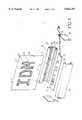
- FIG. 1is an exploded view showing a luminant sign in accordance with the present invention
- FIG. 2is a cross-sectional side view showing a combined structure of the luminant sign in accordance with the present invention
- FIG. 3is a cross-sectional side view along line 3--3 of FIG. 1, showing display areas of the luminant sign in accordance with the present invention
- FIG. 4is a schematic view showing the reflecting effect of the display areas cooperated with an illuminator of the luminant sign in accordance with the present invention
- FIG. 5is a diagram showing a circuit of the luminant sign in accordance with the present invention.
- FIG. 6is a front view showing a conventional luminant sign.
- a luminant sign in accordance with the present inventionincludes a base 100 consisting of a combined pair of opposed casings 10 and an image plate 40 engaged with the base 100.
- the pair of opposed casings 10are "U" shaped and each has two parallel ridges 121 integrally extending from an inner face thereof to define a channel 12 therebetween, whereby, a circuit board 21 with a plurality of illuminators 20 can be received within respective channels 12 defined in the pair of opposed casings 10.
- the circuit board 21is connected to a charger 23, and a regulator 25 via a power supply 27 as shown in FIG. 5 to enable the illuminators 20 to emit light.
- the amount of the illuminators 20can be adjusted according to requirements, in FIG. 1, for example, there may be fewer illuminators 20 below the word "I" than below the word “B” in order to improve the usage of illuminators 20. If the image plate 40 is wide and long, laser diodes with high intensity of light can be used as the illuminators 20.
- each casing 10further has two ledges 13 respectively extending from a top and a bottom of the inner face thereof.
- a cross section of each ledge 13is shaped as a hook such that a pair of enclosure covers 30 can be engaged with two ends of the base 100 in a manner that two pairs of bosses 31 formed on each enclosure cover 30 are respectively received by the corresponding hooks defined by the ledges 13.
- One of the pair of enclosure covers 30defines a plurality of through holes 32 at appropriate positions therein through which a group of wires (not numbered) connected with the circuit board 21 can extend.
- one of the pair of opposed casings 10has a pair of protrusions 11 with screw holes (not numbered) therein integrally formed at an appropriate position on the inner face thereof and the image plate 40 defines a pair of holes 41 aligned with the screw holes of the casing 10, therefore, the image plate 40 can be secured with the casing 10 by a pair of screws (not numbered) extending through the screw holes and the holes 41, as shown in FIG. 2.
- one or both of the opposed casings 100has a cutout defined in a top edge thereof to accommodate the image plate 40.
- the image plate 40is made of transparent materials, such as acrylic resin.
- a front face and a rear face of the image plate 40have a number of display areas 42 thereon defined by peripheral grooves 43 of some pictures or words which are to be represented.
- Each display area 42has a plurality of reflective surfaces 44 formed therein in directions non-parallel to the beam directions of the illuminators 20 on the circuit board 21.
- the reflective surfaces 44are defined by recesses 45 which are parallel to each other.
- the peripheral grooves 43have groove portions which extend in a direction parallel to said recesses and other groove portions which extend in a direction which is nonparallel to the recesses 45. It is to be noted that a depth and an inclination of each reflective surface 44 can be varied during manufacture, depending on the requirements of constructions, for example, a side view of the display area 42 in FIG. 3 is prismatic-like.
- the image plate 40is firstly engaged with one of the casings 10 in the above manner. Then the other casing 10 is abutted to the casing 10 with the image plate 40 and the circuit board 21 is inserted into the channels 12 defined by the pair of casings 10. Finally, the pair of enclosure covers 30 is engaged with both of the two ends of the casings 10 and secures together the two casings 10 by means of the bosses 31 received by the hooks of the casings 10.
Landscapes
- Physics & Mathematics (AREA)
- General Physics & Mathematics (AREA)
- Optics & Photonics (AREA)
- Engineering & Computer Science (AREA)
- Theoretical Computer Science (AREA)
- Illuminated Signs And Luminous Advertising (AREA)
- Display Devices Of Pinball Game Machines (AREA)
- Pinball Game Machines (AREA)
Abstract
Description
1. Field of the Invention
The present invention relates to a luminant sign, and more particularly to a luminant sign whose display areas have a uniform intensity of light which shows clearly the message disposed therein.
2. Description of Related Art
Signs are used popularly in many places to draw the consumers' or users' attention. For example, signs are commonly used for indicating a telephone booth, a washroom, an exit or an entrance, and so on. Alternatively, signs, particularly luminant signs are used for advertisement purposes.
A kind of conventional luminant sign has a structure as shown in FIG. 6. The luminant sign has abase 50 includes a combined front and a rear casing (not numbered). One side of thebase 50 defines ahole 52 such that thebase 50 can be mounted to a wall. Thebase 50 has afluorescent lamp 51 equipped with a stabilizer disposed therein. The luminant sign further has animage plate 60 made of transparent acrylic material. One side of theimage plate 60 is gripped between the front and the rear casing. Theimage plate 60 has a number ofdisplay areas 62 defined thereon byperipheral grooves 61 of some pictures or words which are to be indicated. When thefluorescent lamp 51 illuminates theimage plate 60, eachdisplay area 62 will become clear because of reflection of light. Though this kind of image plate has a luminant effect, it still has a disadvantage that the display area can not represent a uniform intensity of light such that the advertisement effect will be decreased and furthermore, the display area with lower intensity of light may be misunderstood by the users. The reason is that thefluorescent lamp 51 is located at one side of theimage plate 60 such that thedisplay areas 62 near the light source will be brighter (as the "A" area shown in FIG. 6) and thedisplay areas 62 far from the light source will be relatively fainter (as the "B" area shown in FIG. 6).
The present invention provides an improved luminant sign to mitigate and/or obviate the aforementioned problems.
One object of the present invention is to provide a luminant sign whose display areas have a uniform intensity of reflective light.
In accordance with one aspect of the present invention, a luminant sign comprises a base combined with a pair of opposed casings and a image plate engaged with the base. The base has a circuit board with a plurality of illuminators mounted thereon. The image plate is made of transparent material, such as acrylic resin. A front face and a rear face of the image plate each has a number of display areas thereon defined by peripheral grooves of pictures or words. Each display area has a plurality of reflective surfaces defined therein in directions non-parallel to the beam directions of the illuminators.
In accordance with another aspect of the present invention, the pair of opposed casings are "U" shaped and each has two parallel ridges integrally extending from an inner face thereof. Each pair of the ridges defines a channel therebetween to receive the circuit board.
In accordance with a further aspect of the present invention, each of the pair of opposed casings further has two ledges integrally extending from a top and a bottom inner face thereof. Each of the ledges is formed as a hook such that a pair of enclosure covers can be engaged with two ends of the pair of opposed casings in a manner that two pairs of bosses integrally formed on the enclosure covers are respectively received in the corresponding ledges.
In accordance with still a further aspect of the present invention, one of the pair of opposed casings further has two protrusions integrally formed at an appropriate position of the inner face thereof. Each protrusion defines a screw hole therein, and wherein said image plate defines two holes respectively aligned with the screw holes of the protrusions such that the image plate can be engaged with the casing by means of two screws respectively extending through the hole and the screw holes.
Other objects, advantages and novel features of the invention will become more apparent from the following detailed description when taken in conjunction with the accompanying drawings.
FIG. 1 is an exploded view showing a luminant sign in accordance with the present invention;
FIG. 2 is a cross-sectional side view showing a combined structure of the luminant sign in accordance with the present invention;
FIG. 3 is a cross-sectional side view alongline 3--3 of FIG. 1, showing display areas of the luminant sign in accordance with the present invention;
FIG. 4 is a schematic view showing the reflecting effect of the display areas cooperated with an illuminator of the luminant sign in accordance with the present invention;
FIG. 5 is a diagram showing a circuit of the luminant sign in accordance with the present invention; and
FIG. 6 is a front view showing a conventional luminant sign.
Referring to the Figures and especially to FIG. 1 and FIG. 2, a luminant sign in accordance with the present invention includes abase 100 consisting of a combined pair ofopposed casings 10 and animage plate 40 engaged with thebase 100.
The pair ofopposed casings 10 are "U" shaped and each has twoparallel ridges 121 integrally extending from an inner face thereof to define achannel 12 therebetween, whereby, acircuit board 21 with a plurality ofilluminators 20 can be received withinrespective channels 12 defined in the pair ofopposed casings 10.
Thecircuit board 21 is connected to a charger 23, and a regulator 25 via a power supply 27 as shown in FIG. 5 to enable theilluminators 20 to emit light. The amount of theilluminators 20 can be adjusted according to requirements, in FIG. 1, for example, there may befewer illuminators 20 below the word "I" than below the word "B" in order to improve the usage ofilluminators 20. If theimage plate 40 is wide and long, laser diodes with high intensity of light can be used as theilluminators 20.
Still referring to FIG. 1 and FIG. 2, eachcasing 10 further has twoledges 13 respectively extending from a top and a bottom of the inner face thereof. A cross section of eachledge 13 is shaped as a hook such that a pair of enclosure covers 30 can be engaged with two ends of thebase 100 in a manner that two pairs ofbosses 31 formed on eachenclosure cover 30 are respectively received by the corresponding hooks defined by theledges 13. One of the pair of enclosure covers 30 defines a plurality of throughholes 32 at appropriate positions therein through which a group of wires (not numbered) connected with thecircuit board 21 can extend.
Also, one of the pair ofopposed casings 10 has a pair of protrusions 11 with screw holes (not numbered) therein integrally formed at an appropriate position on the inner face thereof and theimage plate 40 defines a pair ofholes 41 aligned with the screw holes of thecasing 10, therefore, theimage plate 40 can be secured with thecasing 10 by a pair of screws (not numbered) extending through the screw holes and theholes 41, as shown in FIG. 2. It is to be noted that one or both of theopposed casings 100 has a cutout defined in a top edge thereof to accommodate theimage plate 40.
Theimage plate 40 is made of transparent materials, such as acrylic resin. With a reference to FIG. 3, a front face and a rear face of theimage plate 40 have a number ofdisplay areas 42 thereon defined byperipheral grooves 43 of some pictures or words which are to be represented. Eachdisplay area 42 has a plurality ofreflective surfaces 44 formed therein in directions non-parallel to the beam directions of theilluminators 20 on thecircuit board 21. Thereflective surfaces 44 are defined byrecesses 45 which are parallel to each other. Theperipheral grooves 43 have groove portions which extend in a direction parallel to said recesses and other groove portions which extend in a direction which is nonparallel to therecesses 45. It is to be noted that a depth and an inclination of eachreflective surface 44 can be varied during manufacture, depending on the requirements of constructions, for example, a side view of thedisplay area 42 in FIG. 3 is prismatic-like.
Referring to FIG. 4, with the prismatic-likereflective surfaces 44, when theilluminator 20 illuminates thedisplay area 42, a part of the light from theilluminator 20 is reflected, by somereflective surfaces 44 and directly sent to outside, other parts of the light from theilluminator 20 are continuously and repeatedly reflected by some otherreflective surfaces 44 such that almost any position (including the peripheral grooves 43) in thedisplay area 42 has the same probability to receive the light from theilluminator 20, thereby achieving a uniform brilliance.
In assembly, theimage plate 40 is firstly engaged with one of thecasings 10 in the above manner. Then theother casing 10 is abutted to thecasing 10 with theimage plate 40 and thecircuit board 21 is inserted into thechannels 12 defined by the pair ofcasings 10. Finally, the pair of enclosure covers 30 is engaged with both of the two ends of thecasings 10 and secures together the twocasings 10 by means of thebosses 31 received by the hooks of thecasings 10.
It is to be understood, however, that even though numerous characteristics and advantages of the present invention have been set forth in the foregoing description, together with details of the structure and function of the invention, the disclosure is illustrative only, and changes may be made in detail, especially in matters of shape, size, and arrangement of parts within the principles of the invention to the full extent indicated by the broad-general meaning of the terms in which the appended claims are expressed.
Claims (12)
1. A luminant sign comprising:
a base having a pair of U-shaped opposed casings;
an image plate made of transparent material and engaged with said base;
said base having a circuit board with at least one illuminator mounted thereon, each said illuminator projecting light in a first direction, and each of said casings having a cutout defined in a top edge thereof to receive said image plate and board retaining means integrally extending from an inner face of at least one of said casings for receiving and retaining said circuit board;
a front face and a rear face of said image plate having a plurality of display areas defined by peripheral grooves having the shape of pictures or words, each said display area having a plurality of reflective surfaces defined therein, said reflective surfaces being formed by a plurality of parallel recesses, said peripheral grooves having groove portions which extend in a direction parallel to said recesses and other groove portions which extend in a direction which is nonparallel to said recesses, said surfaces being disposed on said plate to project in directions non-parallel to said light direction of said at least one illuminator.
2. The luminant sign as claimed in claim 1, wherein said board retaining means includes each casing having two ridges integrally extending from an inner face thereof, said two ridges defining a channel therebetween to receive the circuit board.
3. The luminant sign as claimed in claim 2, wherein said illuminators are light-emitting diodes (LED).
4. The luminant sign as claimed in claim 1, wherein each of said pair of opposed casings further has two ledges integrally extending from a top and a bottom inner face thereof, each of said ledges being hook-like and a pair of enclosure covers respectively engageable with two ends of said pair of opposed casings by means of two pairs of bosses integrally formed on said enclosure covers being respectively received in said ledges.
5. The luminant sign as claimed in claim 4, wherein at least one of said enclosure covers defines at least one through hole therein for wires electrically connected with said circuit board to be extended therethrough.
6. The luminant sign as claimed in claim 1, wherein one of said pair of opposed casings further has an inner face, and two protrusions integrally formed at an appropriate position of said inner face, each protrusion defining a screw hole therein, and wherein said image plate defines two holes respectively aligned with the screw holes of the protrusions such that the image plate can be engaged with the casing by means of fasteners extending through the holes and screw holes.
7. The luminant sign as claimed in claim 1, wherein a depth of the reflective surfaces is smaller than that of the peripheral grooves.
8. The luminant sign as claimed in claim 1, wherein a depth of the reflective surfaces is larger than that of the peripheral grooves.
9. The luminant sign as claimed in claim 1, wherein a depth of the reflective surfaces is equal to that of the peripheral grooves.
10. The luminant sign as claimed in claim 1, wherein said transparent material is acrylic resin.
11. A luminant sign comprising:
a base having a pair of U-shaped opposed casings, said base having a circuit board with a plurality of illuminators and each of said casings having a cutout defined in a top edge thereof;
an image plate made of transparent material and engaged with said base in which a front face and a rear face of the image plate having a number of display areas thereon defined by peripheral grooves of pictures or words, each display area having a plurality of reflective surfaces formed therein in directions non-parallel to beam directions of the illuminators;
each of said pair of opposed casings further has two ledges integrally extending from a top and a bottom inner face thereof, each of said ledges being hook-like, and a pair of enclosure covers respectively engaged with two ends of said pair of opposed casings by means of two pairs of bosses integrally formed on said enclosure covers being respectively received in said ledges.
12. A luminant sign comprising:
a base having a pair of U-shaped opposed casings, each said casing having two ridges internally extending from an inner face thereof, said two ridges defining a channel therebetween to receive the circuit board, each of said pair of opposed casings further having two ledges integrally extending from a top and a bottom inner face thereof, each of said ledges being hook-like, and a pair of enclosure covers respectively engageable with two ends of said pair of opposed casings by means of two pairs of bosses integrally formed on said enclosure covers being respectively received in said ledges;
an image plate made of transparent material and engaged with said base;
said base having a circuit board with at least one illuminator mounted thereon, each said illuminator projecting light in a first direction, and each of said casings having a cutout defined in a top edge thereof to receive said image plate and board retaining means integrally extending from an inner face of at least one of said casings for receiving and retaining said circuit board;
a front face and a rear face of said image plate having a plurality of display areas defined by peripheral grooves having the shape of pictures or words, each said display area having a plurality of reflective surfaces defined therein, said reflective surfaces being formed by a plurality of parallel recesses, said peripheral grooves having groove portions which extend in a direction parallel to said recesses and other groove portions which extend in a direction which is nonparallel to said recesses, said surfaces being disposed on said plate to project in directions non-parallel to said light direction of said at least one illuminator.
Priority Applications (4)
| Application Number | Priority Date | Filing Date | Title |
|---|---|---|---|
| US08/795,304US5842297A (en) | 1997-02-04 | 1997-02-04 | Luminant sign |
| AU12525/97AAU684700B3 (en) | 1997-02-04 | 1997-02-04 | Luminant sign |
| GB9702197AGB2321992B (en) | 1997-02-04 | 1997-02-04 | Luminant sign |
| DE29702428UDE29702428U1 (en) | 1997-02-04 | 1997-02-14 | Illuminated sign |
Applications Claiming Priority (4)
| Application Number | Priority Date | Filing Date | Title |
|---|---|---|---|
| US08/795,304US5842297A (en) | 1997-02-04 | 1997-02-04 | Luminant sign |
| AU12525/97AAU684700B3 (en) | 1997-02-04 | 1997-02-04 | Luminant sign |
| GB9702197AGB2321992B (en) | 1997-02-04 | 1997-02-04 | Luminant sign |
| DE29702428UDE29702428U1 (en) | 1997-02-04 | 1997-02-14 | Illuminated sign |
Publications (1)
| Publication Number | Publication Date |
|---|---|
| US5842297Atrue US5842297A (en) | 1998-12-01 |
Family
ID=27422503
Family Applications (1)
| Application Number | Title | Priority Date | Filing Date |
|---|---|---|---|
| US08/795,304Expired - Fee RelatedUS5842297A (en) | 1997-02-04 | 1997-02-04 | Luminant sign |
Country Status (4)
| Country | Link |
|---|---|
| US (1) | US5842297A (en) |
| AU (1) | AU684700B3 (en) |
| DE (1) | DE29702428U1 (en) |
| GB (1) | GB2321992B (en) |
Cited By (65)
| Publication number | Priority date | Publication date | Assignee | Title |
|---|---|---|---|---|
| US5950340A (en)* | 1999-02-02 | 1999-09-14 | Woo; Fay Kan-Kyone | Sign box |
| US6023869A (en)* | 1998-11-10 | 2000-02-15 | Lumenids, Ltd. | Illuminated sign |
| US6048075A (en)* | 1998-12-09 | 2000-04-11 | Lai; Ten-Ta | Sign box frame having cover board parallel rails, and plurality of transparent lamp holders and lamps for mounting on a wall |
| WO2001050444A1 (en)* | 2000-01-06 | 2001-07-12 | Koninklijke Philips Electronics N.V. | Luminaire and light-emitting panel |
| US6305109B1 (en)* | 1999-12-09 | 2001-10-23 | Chi-Huang Lee | Structure of signboard |
| US6481131B2 (en)* | 2000-10-03 | 2002-11-19 | Amanda Gianotti | LED illuminated plaque |
| US6481130B1 (en)* | 2000-08-11 | 2002-11-19 | Leotek Electronics Corporation | Light emitting diode linear array with lens stripe for illuminated signs |
| US6481870B2 (en)* | 2000-02-12 | 2002-11-19 | Jae-Sul Son | Emergency lighting fixture |
| US6530164B2 (en)* | 2000-05-12 | 2003-03-11 | Giorgio Gai | Luminous diffused light panel with low energy consumption and limited thickness |
| US20030049007A1 (en)* | 2001-09-13 | 2003-03-13 | Matthew Sommers | Optical wave guide |
| KR20030026657A (en)* | 2001-09-26 | 2003-04-03 | 박성진 | Carved Illumination Signboard Using Light-passing Resin and Method for Fabricating Same |
| WO2003036598A1 (en)* | 2001-10-23 | 2003-05-01 | World Lit Corporation | Sign panel using ambient or artificial light |
| US6557282B1 (en) | 2001-02-02 | 2003-05-06 | Ilight Technologies, Inc. | Portable illuminated outdoor advertising display |
| US6592238B2 (en) | 2001-01-31 | 2003-07-15 | Light Technologies, Inc. | Illumination device for simulation of neon lighting |
| US20030235055A1 (en)* | 2002-06-21 | 2003-12-25 | Pervaiz Lodhie | LED light bulb for use in an illuminated aircraft sign |
| KR20040011325A (en)* | 2002-07-29 | 2004-02-05 | 백정호 | Door having Illumination effect |
| US6691443B1 (en)* | 2002-09-20 | 2004-02-17 | Lektron, Inc. | Alpha-numeric/graphic display board illuminator |
| US20040196636A1 (en)* | 2003-04-03 | 2004-10-07 | Atto Co., Ltd. | Light emitting diode assembly for an illuminated sign |
| US20040226202A1 (en)* | 2003-05-15 | 2004-11-18 | Hillstrom Brian J. | Light panel |
| KR100460152B1 (en)* | 2002-07-29 | 2004-12-04 | 김대룡 | Advertisement panel frame of lighting way |
| EP1484547A2 (en) | 2003-06-02 | 2004-12-08 | Pervaiz Lodhie | LED light bulb for use in an illuminated aircraft sign |
| EP1489584A1 (en)* | 2003-06-19 | 2004-12-22 | Alrec Sign & Display B.V. | Illuminable sign |
| US6874924B1 (en) | 2002-03-14 | 2005-04-05 | Ilight Technologies, Inc. | Illumination device for simulation of neon lighting |
| KR100498165B1 (en)* | 2002-07-26 | 2005-07-01 | 김대룡 | Advertisement panel frame of lighting way |
| US20050219860A1 (en)* | 2004-03-31 | 2005-10-06 | Schexnaider Craig J | Light panel illuminated by light emitting diodes |
| US20050255296A1 (en)* | 2004-05-11 | 2005-11-17 | Robbins Edward S Iii | Desk pad |
| US7008097B1 (en) | 2003-02-25 | 2006-03-07 | Ilight Technologies, Inc. | Illumination device for simulating neon or fluorescent lighting including a waveguide and a scattering cap |
| US7118251B1 (en) | 2003-05-23 | 2006-10-10 | Ilight Technologies, Inc. | Illumination device for simulating channel letters |
| WO2006079319A3 (en)* | 2005-01-27 | 2006-10-19 | Iistone Gmbh | Decorative element |
| US20060232980A1 (en)* | 2005-04-19 | 2006-10-19 | Wen-Shou Wang | Structure of a light and sign assembly for showing the direction of an emergency exit |
| US20060289054A1 (en)* | 2005-06-22 | 2006-12-28 | Carmanah Technologies Corp. | Solar powered light emitting diode illuminated display panel assembly |
| US20060291241A1 (en)* | 2005-06-22 | 2006-12-28 | Carmanah Technologies Corp. | Light emitting diode illuminated display panel assembly |
| US20070030693A1 (en)* | 2003-04-02 | 2007-02-08 | Dennis Karlsson | Convex luminant sign |
| US20070062085A1 (en)* | 2005-09-01 | 2007-03-22 | Frank Pan | Sign panel arrangement with three-dimensional illumination effect |
| USD539851S1 (en)* | 2005-11-14 | 2007-04-03 | Rufus Dixon | Emergency sign for vehicles |
| US20070103902A1 (en)* | 2005-11-08 | 2007-05-10 | Yu-Hsiang Hsiao | Lighting fixture |
| US20070147034A1 (en)* | 2005-12-28 | 2007-06-28 | Xuliang Li | Transparent Plate with Color-Changeable Lighting Image |
| US20070283604A1 (en)* | 2006-05-22 | 2007-12-13 | Kaoh Andy K F | Method and apparatus for simulating the appearance of a neon sign |
| US20070298751A1 (en)* | 2006-06-21 | 2007-12-27 | Thomas Wulff | System and method for monitoring a mobile device |
| US20080019121A1 (en)* | 2006-07-24 | 2008-01-24 | Mesa Design Llc | Illuminated tile and method of producing the same |
| USD573499S1 (en)* | 2007-07-31 | 2008-07-22 | Gary Dale King | Help sign |
| USD580580S1 (en) | 2008-01-11 | 2008-11-11 | Pervaiz Lodhie | Circular light structure |
| USD613885S1 (en) | 2008-06-10 | 2010-04-13 | Pervaiz Lodhie | Two-stage LED light module |
| USD613886S1 (en) | 2008-06-10 | 2010-04-13 | Pervaiz Lodhie | LED light module with cutouts |
| USD614318S1 (en) | 2008-06-10 | 2010-04-20 | Pervaiz Lodhie | LED light module |
| US20100100623A1 (en)* | 2004-04-06 | 2010-04-22 | Thomas Wulff | System and method for monitoring a mobile computing product/arrangement |
| USD620189S1 (en)* | 2009-05-22 | 2010-07-20 | Coleman Hill | Protective casing for exterior lighting fixtures |
| US20100188601A1 (en)* | 2009-01-29 | 2010-07-29 | Tomohisa Onishi | Light emitting diode backlight unit and liquid crystal display device having the same |
| US20100199533A1 (en)* | 2009-02-09 | 2010-08-12 | Robert Tsai | Display box with LEDs |
| US7784967B2 (en) | 2007-10-30 | 2010-08-31 | Pervaiz Lodhie | Loop LED light |
| US7862204B2 (en) | 2007-10-25 | 2011-01-04 | Pervaiz Lodhie | LED light |
| USD631567S1 (en) | 2008-01-11 | 2011-01-25 | Pervaiz Lodhie | LED bulb |
| US7942542B1 (en) | 2008-06-20 | 2011-05-17 | Gary Dunn | Back lighted replaceable image sheet display apparatus |
| CN102271475A (en)* | 2010-06-04 | 2011-12-07 | 深圳富泰宏精密工业有限公司 | Electronic device |
| US20120188755A1 (en)* | 2009-09-16 | 2012-07-26 | Tridonic Jennersdorf Gmbh | LED Luminous Element for Illuminating a Light Box Having Homogeneous Light Distribution |
| US8234804B1 (en)* | 2005-05-31 | 2012-08-07 | Janet Rush | Laser etched article with illuminable housing |
| US8322883B2 (en) | 2003-02-04 | 2012-12-04 | Ilight Technologies, Inc. | Flexible illumination device for simulating neon lighting |
| US20140022822A1 (en)* | 2012-07-17 | 2014-01-23 | Samsung Display Co., Ltd. | Backlight assembly and display device having the same |
| US20150062867A1 (en)* | 2013-09-04 | 2015-03-05 | Hon Hai Precision Industry Co., Ltd. | Electronic device with reflection member |
| US9128222B1 (en)* | 2013-07-18 | 2015-09-08 | Automated Assembly Corporation | LED lighting apparatus |
| US20180360119A1 (en)* | 2017-06-19 | 2018-12-20 | Tma Labs Llc | Portable Aerosol Devices and Methods Thereof |
| US10163377B2 (en)* | 2016-10-13 | 2018-12-25 | Laser's Edge, LLC | Programmable base to hold and illuminate a panel assembly |
| US10317614B1 (en) | 2017-03-14 | 2019-06-11 | Automatad Assembly Corporation | SSL lighting apparatus |
| US10655823B1 (en) | 2019-02-04 | 2020-05-19 | Automated Assembly Corporation | SSL lighting apparatus |
| US10995931B1 (en) | 2020-08-06 | 2021-05-04 | Automated Assembly Corporation | SSL lighting apparatus |
Families Citing this family (2)
| Publication number | Priority date | Publication date | Assignee | Title |
|---|---|---|---|---|
| AT411635B (en)* | 1999-10-06 | 2004-03-25 | Schnurrer Anton | ILLUMINATED POSTER SETUP |
| GB0018132D0 (en)* | 2000-07-24 | 2000-09-13 | Gradus Ltd | Lighting system |
Citations (9)
| Publication number | Priority date | Publication date | Assignee | Title |
|---|---|---|---|---|
| AU81431A (en)* | 1931-02-19 | 1931-07-02 | Thegeneral Electric Company Limited | Improvements in luminous signs comprising electric luminous discharge tubes |
| US3399476A (en)* | 1965-02-01 | 1968-09-03 | James F. Davis | Animated sign |
| US3605303A (en)* | 1969-01-27 | 1971-09-20 | Cornelius Co | Sign construction |
| US3748769A (en)* | 1971-10-01 | 1973-07-31 | A Nolles | Animated display device |
| GB2030750A (en)* | 1978-10-04 | 1980-04-10 | Pierre Lo International Ltd | Illuminated signs |
| US4697365A (en)* | 1985-09-25 | 1987-10-06 | Xebron Corporation | Edge-illuminated sign |
| US5215285A (en)* | 1991-12-13 | 1993-06-01 | Lewis Richard G | Display card holder |
| US5433024A (en)* | 1993-10-04 | 1995-07-18 | Displayonix Corp. | Edge-lighted display |
| US5640792A (en)* | 1995-06-07 | 1997-06-24 | National Service Industries, Inc. | Lighting fixtures |
Family Cites Families (2)
| Publication number | Priority date | Publication date | Assignee | Title |
|---|---|---|---|---|
| US4948242A (en)* | 1988-03-22 | 1990-08-14 | Donnelly Mirrors Limited | Vehicle rearview mirror assembly |
| AU662813B2 (en)* | 1992-03-26 | 1995-09-14 | Sir Harry Flashman & Associates | Identification plate and method of manufacture |
- 1997
- 1997-02-04AUAU12525/97Apatent/AU684700B3/ennot_activeCeased
- 1997-02-04USUS08/795,304patent/US5842297A/ennot_activeExpired - Fee Related
- 1997-02-04GBGB9702197Apatent/GB2321992B/ennot_activeExpired - Fee Related
- 1997-02-14DEDE29702428Upatent/DE29702428U1/ennot_activeExpired - Lifetime
Patent Citations (9)
| Publication number | Priority date | Publication date | Assignee | Title |
|---|---|---|---|---|
| AU81431A (en)* | 1931-02-19 | 1931-07-02 | Thegeneral Electric Company Limited | Improvements in luminous signs comprising electric luminous discharge tubes |
| US3399476A (en)* | 1965-02-01 | 1968-09-03 | James F. Davis | Animated sign |
| US3605303A (en)* | 1969-01-27 | 1971-09-20 | Cornelius Co | Sign construction |
| US3748769A (en)* | 1971-10-01 | 1973-07-31 | A Nolles | Animated display device |
| GB2030750A (en)* | 1978-10-04 | 1980-04-10 | Pierre Lo International Ltd | Illuminated signs |
| US4697365A (en)* | 1985-09-25 | 1987-10-06 | Xebron Corporation | Edge-illuminated sign |
| US5215285A (en)* | 1991-12-13 | 1993-06-01 | Lewis Richard G | Display card holder |
| US5433024A (en)* | 1993-10-04 | 1995-07-18 | Displayonix Corp. | Edge-lighted display |
| US5640792A (en)* | 1995-06-07 | 1997-06-24 | National Service Industries, Inc. | Lighting fixtures |
Cited By (97)
| Publication number | Priority date | Publication date | Assignee | Title |
|---|---|---|---|---|
| US6023869A (en)* | 1998-11-10 | 2000-02-15 | Lumenids, Ltd. | Illuminated sign |
| US6076294A (en)* | 1998-11-10 | 2000-06-20 | Lumenids, Ltd. | Illuminated sign |
| WO2000028509A3 (en)* | 1998-11-10 | 2000-07-27 | Lumenids Ltd | Illuminated sign |
| GB2349499A (en)* | 1998-11-10 | 2000-11-01 | Lumenids Limited | Illuminated sign |
| AU738258B2 (en)* | 1998-11-10 | 2001-09-13 | Lumenids, Ltd. | Illuminated sign |
| US6048075A (en)* | 1998-12-09 | 2000-04-11 | Lai; Ten-Ta | Sign box frame having cover board parallel rails, and plurality of transparent lamp holders and lamps for mounting on a wall |
| US5950340A (en)* | 1999-02-02 | 1999-09-14 | Woo; Fay Kan-Kyone | Sign box |
| US6305109B1 (en)* | 1999-12-09 | 2001-10-23 | Chi-Huang Lee | Structure of signboard |
| US6539656B2 (en) | 2000-01-06 | 2003-04-01 | Koninklijke Philips Electronics N.V. | Luminaire and light-emitting panel |
| US6745506B2 (en)* | 2000-01-06 | 2004-06-08 | Koninklijke Philips Electronics N.V. | Luminaire and light-emitting panel |
| WO2001050444A1 (en)* | 2000-01-06 | 2001-07-12 | Koninklijke Philips Electronics N.V. | Luminaire and light-emitting panel |
| US6481870B2 (en)* | 2000-02-12 | 2002-11-19 | Jae-Sul Son | Emergency lighting fixture |
| US6530164B2 (en)* | 2000-05-12 | 2003-03-11 | Giorgio Gai | Luminous diffused light panel with low energy consumption and limited thickness |
| AU775548B2 (en)* | 2000-05-12 | 2004-08-05 | Ing. Giorgio Gai | Luminous diffused light panel with low energy consumption and limited thickness |
| US6481130B1 (en)* | 2000-08-11 | 2002-11-19 | Leotek Electronics Corporation | Light emitting diode linear array with lens stripe for illuminated signs |
| US6481131B2 (en)* | 2000-10-03 | 2002-11-19 | Amanda Gianotti | LED illuminated plaque |
| US6592238B2 (en) | 2001-01-31 | 2003-07-15 | Light Technologies, Inc. | Illumination device for simulation of neon lighting |
| US6557282B1 (en) | 2001-02-02 | 2003-05-06 | Ilight Technologies, Inc. | Portable illuminated outdoor advertising display |
| US20030049007A1 (en)* | 2001-09-13 | 2003-03-13 | Matthew Sommers | Optical wave guide |
| US6966684B2 (en)* | 2001-09-13 | 2005-11-22 | Gelcore, Llc | Optical wave guide |
| KR20030026657A (en)* | 2001-09-26 | 2003-04-03 | 박성진 | Carved Illumination Signboard Using Light-passing Resin and Method for Fabricating Same |
| US6612055B2 (en)* | 2001-10-23 | 2003-09-02 | World Lit Corporaion | Sign panel using ambient or artificial light |
| WO2003036598A1 (en)* | 2001-10-23 | 2003-05-01 | World Lit Corporation | Sign panel using ambient or artificial light |
| US6874924B1 (en) | 2002-03-14 | 2005-04-05 | Ilight Technologies, Inc. | Illumination device for simulation of neon lighting |
| US20030235055A1 (en)* | 2002-06-21 | 2003-12-25 | Pervaiz Lodhie | LED light bulb for use in an illuminated aircraft sign |
| US6886963B2 (en) | 2002-06-21 | 2005-05-03 | Pervaiz Lodhie | LED light bulb for use in an illuminated aircraft sign |
| KR100498165B1 (en)* | 2002-07-26 | 2005-07-01 | 김대룡 | Advertisement panel frame of lighting way |
| KR20040011325A (en)* | 2002-07-29 | 2004-02-05 | 백정호 | Door having Illumination effect |
| KR100460152B1 (en)* | 2002-07-29 | 2004-12-04 | 김대룡 | Advertisement panel frame of lighting way |
| US6691443B1 (en)* | 2002-09-20 | 2004-02-17 | Lektron, Inc. | Alpha-numeric/graphic display board illuminator |
| US8322883B2 (en) | 2003-02-04 | 2012-12-04 | Ilight Technologies, Inc. | Flexible illumination device for simulating neon lighting |
| US7008097B1 (en) | 2003-02-25 | 2006-03-07 | Ilight Technologies, Inc. | Illumination device for simulating neon or fluorescent lighting including a waveguide and a scattering cap |
| US20070030693A1 (en)* | 2003-04-02 | 2007-02-08 | Dennis Karlsson | Convex luminant sign |
| US6924973B2 (en)* | 2003-04-03 | 2005-08-02 | Atto Display Co., Ltd. | Light emitting diode assembly for an illuminated sign |
| US20040196636A1 (en)* | 2003-04-03 | 2004-10-07 | Atto Co., Ltd. | Light emitting diode assembly for an illuminated sign |
| US20040226202A1 (en)* | 2003-05-15 | 2004-11-18 | Hillstrom Brian J. | Light panel |
| US6895705B2 (en) | 2003-05-15 | 2005-05-24 | Marketing Display, Inc. | Light panel |
| US7118251B1 (en) | 2003-05-23 | 2006-10-10 | Ilight Technologies, Inc. | Illumination device for simulating channel letters |
| EP1484547A2 (en) | 2003-06-02 | 2004-12-08 | Pervaiz Lodhie | LED light bulb for use in an illuminated aircraft sign |
| WO2004111979A1 (en)* | 2003-06-19 | 2004-12-23 | Alrec Sign & Display B.V. | Illuminable sign |
| US20070199218A1 (en)* | 2003-06-19 | 2007-08-30 | Peijun Jiang | Illuminable Signs |
| EP1489584A1 (en)* | 2003-06-19 | 2004-12-22 | Alrec Sign & Display B.V. | Illuminable sign |
| US7374327B2 (en) | 2004-03-31 | 2008-05-20 | Schexnaider Craig J | Light panel illuminated by light emitting diodes |
| US20050219860A1 (en)* | 2004-03-31 | 2005-10-06 | Schexnaider Craig J | Light panel illuminated by light emitting diodes |
| US20100100623A1 (en)* | 2004-04-06 | 2010-04-22 | Thomas Wulff | System and method for monitoring a mobile computing product/arrangement |
| US20110205076A1 (en)* | 2004-04-06 | 2011-08-25 | Symbol Technologies, Inc. | System and method for monitoring a mobile compputing product/arrangement |
| US8773260B2 (en) | 2004-04-06 | 2014-07-08 | Symbol Technologies, Inc. | System and method for monitoring a mobile computing product/arrangement |
| US20050255296A1 (en)* | 2004-05-11 | 2005-11-17 | Robbins Edward S Iii | Desk pad |
| WO2006079319A3 (en)* | 2005-01-27 | 2006-10-19 | Iistone Gmbh | Decorative element |
| US20060232980A1 (en)* | 2005-04-19 | 2006-10-19 | Wen-Shou Wang | Structure of a light and sign assembly for showing the direction of an emergency exit |
| US8234804B1 (en)* | 2005-05-31 | 2012-08-07 | Janet Rush | Laser etched article with illuminable housing |
| US20060291241A1 (en)* | 2005-06-22 | 2006-12-28 | Carmanah Technologies Corp. | Light emitting diode illuminated display panel assembly |
| US20060289054A1 (en)* | 2005-06-22 | 2006-12-28 | Carmanah Technologies Corp. | Solar powered light emitting diode illuminated display panel assembly |
| US20070062085A1 (en)* | 2005-09-01 | 2007-03-22 | Frank Pan | Sign panel arrangement with three-dimensional illumination effect |
| US20070103902A1 (en)* | 2005-11-08 | 2007-05-10 | Yu-Hsiang Hsiao | Lighting fixture |
| USD539851S1 (en)* | 2005-11-14 | 2007-04-03 | Rufus Dixon | Emergency sign for vehicles |
| US20070147034A1 (en)* | 2005-12-28 | 2007-06-28 | Xuliang Li | Transparent Plate with Color-Changeable Lighting Image |
| US7467486B2 (en) | 2006-05-22 | 2008-12-23 | Kaoh Andy K F | Method and apparatus for simulating the appearance of a neon sign |
| US20070283604A1 (en)* | 2006-05-22 | 2007-12-13 | Kaoh Andy K F | Method and apparatus for simulating the appearance of a neon sign |
| US20070298751A1 (en)* | 2006-06-21 | 2007-12-27 | Thomas Wulff | System and method for monitoring a mobile device |
| US8594742B2 (en) | 2006-06-21 | 2013-11-26 | Symbol Technologies, Inc. | System and method for monitoring a mobile device |
| US20080019121A1 (en)* | 2006-07-24 | 2008-01-24 | Mesa Design Llc | Illuminated tile and method of producing the same |
| USD573499S1 (en)* | 2007-07-31 | 2008-07-22 | Gary Dale King | Help sign |
| US8128258B2 (en) | 2007-10-25 | 2012-03-06 | Pervaiz Lodhie | LED light |
| US8157416B2 (en) | 2007-10-25 | 2012-04-17 | Pervaiz Lodhie | LED light |
| US7862204B2 (en) | 2007-10-25 | 2011-01-04 | Pervaiz Lodhie | LED light |
| US7784967B2 (en) | 2007-10-30 | 2010-08-31 | Pervaiz Lodhie | Loop LED light |
| USD631567S1 (en) | 2008-01-11 | 2011-01-25 | Pervaiz Lodhie | LED bulb |
| USD599496S1 (en) | 2008-01-11 | 2009-09-01 | Pervaiz Lodhie | Circular light structure |
| USD580580S1 (en) | 2008-01-11 | 2008-11-11 | Pervaiz Lodhie | Circular light structure |
| USD595886S1 (en) | 2008-01-11 | 2009-07-07 | Pervaiz Lodhie | Circular light structure |
| USD614318S1 (en) | 2008-06-10 | 2010-04-20 | Pervaiz Lodhie | LED light module |
| USD631601S1 (en) | 2008-06-10 | 2011-01-25 | Pervaiz Lodhie | LED light module with cutouts |
| USD630372S1 (en) | 2008-06-10 | 2011-01-04 | Pervaiz Lodhie | Two-stage LED light module |
| USD629957S1 (en) | 2008-06-10 | 2010-12-28 | Pervaiz Lodhie | LED light module |
| USD613886S1 (en) | 2008-06-10 | 2010-04-13 | Pervaiz Lodhie | LED light module with cutouts |
| USD613885S1 (en) | 2008-06-10 | 2010-04-13 | Pervaiz Lodhie | Two-stage LED light module |
| US7942542B1 (en) | 2008-06-20 | 2011-05-17 | Gary Dunn | Back lighted replaceable image sheet display apparatus |
| US20100188601A1 (en)* | 2009-01-29 | 2010-07-29 | Tomohisa Onishi | Light emitting diode backlight unit and liquid crystal display device having the same |
| US8269913B2 (en) | 2009-01-29 | 2012-09-18 | Samsung Electronics Co., Ltd. | Light emitting diode backlight unit and liquid crystal display device having the same |
| US20100199533A1 (en)* | 2009-02-09 | 2010-08-12 | Robert Tsai | Display box with LEDs |
| USD620189S1 (en)* | 2009-05-22 | 2010-07-20 | Coleman Hill | Protective casing for exterior lighting fixtures |
| US8833964B2 (en)* | 2009-09-16 | 2014-09-16 | Tridonic Jennersdorf Gmbh | LED luminous element for illuminating a light box having homogeneous light distribution |
| US20120188755A1 (en)* | 2009-09-16 | 2012-07-26 | Tridonic Jennersdorf Gmbh | LED Luminous Element for Illuminating a Light Box Having Homogeneous Light Distribution |
| US20110296724A1 (en)* | 2010-06-04 | 2011-12-08 | Fih (Hong Kong) Limited | Electronic device with pattern-displaying function |
| CN102271475A (en)* | 2010-06-04 | 2011-12-07 | 深圳富泰宏精密工业有限公司 | Electronic device |
| US9110214B2 (en)* | 2012-07-17 | 2015-08-18 | Samsung Display Co., Ltd. | Backlight assembly and display device having the same |
| US20140022822A1 (en)* | 2012-07-17 | 2014-01-23 | Samsung Display Co., Ltd. | Backlight assembly and display device having the same |
| US9128222B1 (en)* | 2013-07-18 | 2015-09-08 | Automated Assembly Corporation | LED lighting apparatus |
| US20150062867A1 (en)* | 2013-09-04 | 2015-03-05 | Hon Hai Precision Industry Co., Ltd. | Electronic device with reflection member |
| US9542869B2 (en)* | 2013-09-04 | 2017-01-10 | Hon Hai Precision Industry Co., Ltd. | Electronic device with reflection member |
| US10163377B2 (en)* | 2016-10-13 | 2018-12-25 | Laser's Edge, LLC | Programmable base to hold and illuminate a panel assembly |
| US10317614B1 (en) | 2017-03-14 | 2019-06-11 | Automatad Assembly Corporation | SSL lighting apparatus |
| US20180360119A1 (en)* | 2017-06-19 | 2018-12-20 | Tma Labs Llc | Portable Aerosol Devices and Methods Thereof |
| US10939705B2 (en)* | 2017-06-19 | 2021-03-09 | Tma Labs Llc | Portable aerosol devices and methods thereof |
| US10655823B1 (en) | 2019-02-04 | 2020-05-19 | Automated Assembly Corporation | SSL lighting apparatus |
| US10995931B1 (en) | 2020-08-06 | 2021-05-04 | Automated Assembly Corporation | SSL lighting apparatus |
Also Published As
| Publication number | Publication date |
|---|---|
| AU684700B3 (en) | 1997-12-18 |
| GB2321992B (en) | 1999-01-06 |
| GB9702197D0 (en) | 1997-03-26 |
| GB2321992A (en) | 1998-08-12 |
| DE29702428U1 (en) | 1997-04-10 |
Similar Documents
| Publication | Publication Date | Title |
|---|---|---|
| US5842297A (en) | Luminant sign | |
| US5105568A (en) | Illuminated sign having stencil panel and reflector panel | |
| US5433024A (en) | Edge-lighted display | |
| EP1477368B1 (en) | Illuminated license plate for vehicles and vehicle provided with the same | |
| US5954423A (en) | Light distribution diffuser for exit signs and the like illuminated by LED arrays | |
| US5008658A (en) | Domed light housing for back-lit LCD display | |
| US5887968A (en) | Light distribution reflector for exit signs and the illuminated by LED arrays | |
| EP1300824A2 (en) | Liquid crystal display device for use in electronic apparatus | |
| US7797866B2 (en) | Illuminated sign and light source for use with said sign | |
| US20070006493A1 (en) | Illuminated license plate for vehicles and vehicle provided with the same | |
| JP2003519810A (en) | Lighting device and light emitting panel | |
| US6231202B1 (en) | Lighting unit and liquid crystal display device using the same | |
| JP4030050B2 (en) | Surface light source device, image display device, and light guide plate assembly | |
| US7393131B2 (en) | Surface light source having light guide plate with prisms | |
| US20060221632A1 (en) | Signboard using LED light source | |
| US20020036900A1 (en) | Spread illumination apparatus | |
| US5560698A (en) | Lighting apparatus and liquid crystal display device using the same | |
| KR20130062265A (en) | Light display method and light display device | |
| JP3040473U (en) | Luminous indicator | |
| US20030184499A1 (en) | Display device for use in electronics device and light guide plate therefor | |
| US7990492B2 (en) | Liquid crystal display and display device with light source assembly | |
| KR101041976B1 (en) | Advertising signboard | |
| WO2005010853A1 (en) | Illuminated license plate for vehicle comprising such an illuminated license plate | |
| KR20090059996A (en) | Backlight unit and flat panel display device having the same | |
| JP3528261B2 (en) | Backlight for panel |
Legal Events
| Date | Code | Title | Description |
|---|---|---|---|
| AS | Assignment | Owner name:FLYING DRAGONS CO., LTD., TAIWAN Free format text:ASSIGNMENT OF ASSIGNORS INTEREST;ASSIGNOR:TUNG, CHING-YUNG;REEL/FRAME:008469/0771 Effective date:19970131 | |
| REMI | Maintenance fee reminder mailed | ||
| LAPS | Lapse for failure to pay maintenance fees | ||
| STCH | Information on status: patent discontinuation | Free format text:PATENT EXPIRED DUE TO NONPAYMENT OF MAINTENANCE FEES UNDER 37 CFR 1.362 | |
| FP | Expired due to failure to pay maintenance fee | Effective date:20021201 |