US5842130A - Method for identifying a mobile unit in a wireless communication system - Google Patents
Method for identifying a mobile unit in a wireless communication systemDownload PDFInfo
- Publication number
- US5842130A US5842130AUS08/865,319US86531997AUS5842130AUS 5842130 AUS5842130 AUS 5842130AUS 86531997 AUS86531997 AUS 86531997AUS 5842130 AUS5842130 AUS 5842130A
- Authority
- US
- United States
- Prior art keywords
- signal
- communication unit
- base station
- narrowbeam
- mobile communication
- Prior art date
- Legal status (The legal status is an assumption and is not a legal conclusion. Google has not performed a legal analysis and makes no representation as to the accuracy of the status listed.)
- Expired - Lifetime
Links
- 238000000034methodMethods0.000titleclaimsabstractdescription44
- 238000004891communicationMethods0.000titleclaimsabstractdescription39
- 238000010295mobile communicationMethods0.000claimsabstractdescription61
- 230000004913activationEffects0.000claimsdescription6
- 238000001228spectrumMethods0.000claimsdescription5
- 238000013475authorizationMethods0.000claims2
- 230000005540biological transmissionEffects0.000description21
- 238000004364calculation methodMethods0.000description8
- 238000005259measurementMethods0.000description6
- 230000001413cellular effectEffects0.000description5
- 230000006870functionEffects0.000description5
- 230000011664signalingEffects0.000description5
- 239000000969carrierSubstances0.000description1
- 230000010267cellular communicationEffects0.000description1
- 230000003247decreasing effectEffects0.000description1
- 230000001934delayEffects0.000description1
- 230000001419dependent effectEffects0.000description1
- 238000013461designMethods0.000description1
- 230000000694effectsEffects0.000description1
- 230000008030eliminationEffects0.000description1
- 238000003379elimination reactionMethods0.000description1
- 230000007613environmental effectEffects0.000description1
- 230000003993interactionEffects0.000description1
- 238000004519manufacturing processMethods0.000description1
- 238000012545processingMethods0.000description1
- 230000007704transitionEffects0.000description1
- 238000010200validation analysisMethods0.000description1
Images


Classifications
- H—ELECTRICITY
- H04—ELECTRIC COMMUNICATION TECHNIQUE
- H04W—WIRELESS COMMUNICATION NETWORKS
- H04W64/00—Locating users or terminals or network equipment for network management purposes, e.g. mobility management
- H—ELECTRICITY
- H04—ELECTRIC COMMUNICATION TECHNIQUE
- H04W—WIRELESS COMMUNICATION NETWORKS
- H04W16/00—Network planning, e.g. coverage or traffic planning tools; Network deployment, e.g. resource partitioning or cells structures
- H04W16/24—Cell structures
Definitions
- This inventionrelates generally to wireless communication systems, and, more particularly, to a method for identifying a mobile communication unit in a wireless communication system.
- a base station systemsuch as a digital radio frequency (RF) radiotelephone system
- BSSbase station system
- BTSbase station transmitters and receivers
- BSCbase station controller
- RFradio frequency
- Such systemsmay be direct sequence code division multiple access (DS-CDMA) cellular communication systems or CDMA personal communication systems (CDMA PCS), such as set forth in the Telecommunications Industry Association Interim Standard 95A (TIA IS-95A), ANSI J-STD-008 and their subsequent revisions and addenda, or TIA Telecommunications Systems Bulletin, TSB 74: Support for 14.4 kbps Data Rate and PCS Interaction for Wideband Spread Spectrum Cellular Systems", February 1996 the Bulletin!, all incorporated herein by reference. According to these standards, coded communication signals are transmitted in common 1.25 MHz carriers between base stations and mobile stations that are communicating in the service coverage areas of the base stations.
- TIA IS-95ATelecommunications Industry Association Interim Standard 95A
- TSB 74Support for 14.4 kbps Data Rate and PCS Interaction for Wideband Spread Spectrum Cellular Systems
- a mobile station antennawhich radiates in an omni-directional pattern, is capable of radiating a widebeam signal.
- a base station antennais capable of receiving the widebeam signal on an antenna such as an omni-directional antenna, or a sector antenna, sectorization determined by the wireless communication system configuration.
- the service coverage areas of base stationsare arranged to partially overlap in such a manner as to provide a substantially continuous coverage area in which a mobile station receiving service from one base station, or source base station, may be in RF contact with adjacent base station.
- a communication signal associated with the mobile communication unitmay be handed off to an adjacent base station with no interruption in service.
- Trilaterationis a well known procedure used to compute the position of a mobile communication unit relative to three other reference points, for example three base stations.
- GPSGlobal Positioning System
- a method for identifying a mobile communication unitoperates in a wireless communication system.
- the methodincludes receiving at a first base station having a first location, a widebeam signal from a first mobile communication unit having a second location; measuring, by the first base station, a characteristic of the received widebeam signal to form a first widebeam characteristic; receiving the widebeam signal at a second base station having a third location; measuring, by the second base station, the characteristic of the received widebeam signal to form a second widebeam characteristic; receiving, at the first base station, a narrowbeam signal from the first mobile communication unit; measuring, by the first base station, a characteristic of the received narrowbeam signal to form a first narrowbeam characteristic; receiving the narrowbeam signal at the second base station; measuring, by the second base station, the characteristic of the received narrowbeam signal to form a second narrowbeam characteristic; comparing the first widebeam characteristic and the first narrowbeam characteristic to form a first comparison value;
- a method for identifying a mobile communication unitoperates in a wireless communication system.
- the methodincludes establishing a line-of-sight between a first mobile communication unit and a second communication unit; determining a location of the first mobile communication unit; transmitting from the first mobile communication unit to a first base station having a first location, a widebeam signal; transmitting from the first mobile communication unit to a second base station having a second location, the widebeam signal; transmitting from the first mobile communication unit to the first base station, a narrowbeam signal; transmitting from the first mobile communication unit to the second base station, the narrowbeam signal; receiving at the first mobile communication unit from the first base station, a first comparison value; receiving at the first mobile communication unit from the second base station, a second comparison value; based on the first comparison value, and the second comparison value, calculating a region associated with the narrowbeam signal; and receiving at the first mobile communication unit, receiving by the first mobile communication unit, an identity of the second mobile communication unit within the region.
- FIG. 1illustrates a wireless communication system according to a preferred embodiment of the present invention.
- FIG. 2depicts a custom mobile station which operates in the system in FIG. 1, according to a preferred embodiment of the present invention.
- FIG. 3illustrates geographical depiction of a wireless communication system according to a preferred embodiment of the present invention.
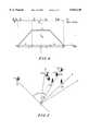
- FIG. 4illustrates an ideal power distribution of narrowbeam transmission angles shown in FIG. 2.
- FIG. 5illustrates an example of calculating region using FIGS. 3 and 4.
- FIG. 6illustrates a call flow of a method for identifying a mobile communication unit according to a preferred embodiment of the present invention.
- FIG. 1illustrates a wireless communication system 200, such as a direct sequence code division multiple access (DS-CDMA) digital radiotelephone system.
- Base stations 298, 294 and 291may communicate with mobile stations 216 and 217, operating within coverage area 220, served by base station 294.
- base stations 298, 294 and 291may communicate with a mobile station 218 operating within coverage area 224 served by base station 298.
- Coverage area 222is served by base station 291.
- Base stationshave fixed locations, such locations chosen to provide overlapping coverage areas.
- Base stations 298, 294, and 291are coupled to a base station controller (BSC) 250, which includes, among other things, a processor 262 and a memory 264 and which is in turn coupled to a mobile switching center (MSC) 260, also including, among other things, a processor 262 and a memory 264.
- BSC and MSCoperate according to well known methods and are commercially available from Motorola, Inc.
- RFradio frequency
- communication signal 213may be transmitted on an IS-95 forward-link channel such as a paging channel or a traffic channel from a "source" base station such as base station 294 to mobile station 216.
- Communication signal 215may be transmitted via an IS-95 reverse-link channel such as an access channel or a traffic channel by mobile station 216 to its source base station, base station 294.
- mobile station 218may be receiving a communication signal (not shown) on a forward-link channel from it's source base station, base station 298, and transmitting a communication signal (not shown) on a reverse-link channel to base station 298.
- mobile registrationmay be implemented.
- Mobile station 216must be powered-up to register, and be registered by, wireless communication system 200.
- Mobile station 216may periodically re-register as it moves through cellular network 200, the registration and re-registration dictated by software parameters, the parameters based on time and/or area, and selected by a system operator.
- a paging messagemay be sent to mobile station 216 as a broadcast page which broadcasts a page to coverage areas served by wireless communication system 200, in order to seek an acknowledgment of mobile station 216's presence on an Access Channel.
- a paging messagemay be sent to mobile station 216 as a zone page which broadcasts the page to a portion of wireless communication system 200, such as coverage areas 220 and 224.
- Boundaries delineating zone sizeare typically selected to encompass a chosen group of coverage areas and are defined by parameters which have been selected and programmed into database software located for example, at the base station controller (BSC) or the mobile switching center (MSC), by the system operator.
- Effective mobile station registrationis predicated on the fact that each mobile station can be uniquely identified by the serving BSC.
- the unique identity assignmentis accomplished prior to a mobile station such as mobile station 216, being released to a subscriber (not shown).
- a mobile stationsuch as mobile station 216 is assigned an electronic serial number (ESN).
- ESNelectronic serial number
- the system operatorupon distributing mobile station 216 to a subscriber, then assigns a unique identity, for example a phone number, a directory number, a mobile identification number, an international mobile identification number (IMSI), or a temporary mobile station identity (TMSI) to mobile station 216.
- the unique identityis associated with the ESN and may be used for tracking and billing activities associated with mobile station 216.
- the unique identity of a second mobile communication unitis facilitated when a region likely to contain mobile station 217 is substantially distinguished from a position likely to contain other mobile stations such as mobile stations 216 and 218.
- a first communication unitspecially customized, for example custom mobile station 319, is enlisted.
- custom mobile station 319may be a standard mobile station well known in the art, to which has been added an activation device 323, a controller 325, and an additional antenna 321.
- Antenna 321may be a directional antenna capable of transmitting a narrowbeam signal 328, manipulation of antenna 321 responsive to controller 325, controller 325 operation initiated by activation device 323.
- Controller 325may be implemented in a variety of ways, for example, using a digital signal processor (DSP).
- Activation device 323may, for example, be an externally mounted button, a switch, or a predetermined sequence entered locally, or entered remotely and then transmitted to mobile station 319.
- target mobile station 217is located at a location T within cellular network 200.
- nine base stations, 290, 291, 292, 293, 291, 294, 296, 297, 298, and 299are shown, although two base stations may be sufficient calculate geographical coordinates associated with a region likely to contain target mobile station 217.
- the positions, longitude and latitude, of base stations 290-299is known.
- the region likely to contain target mobile station 217may be estimated using line-of-sight alignment and radio frequency spread spectrum signal characteristics collected by local base stations.
- radio frequency spread spectrum signal characteristicsmay include widebeam signal strength measurements, narrowbeam signal strength measurements and signal time-of-arrival data, measured with respect to a reference axis.
- the radio frequency spread spectrum signal characteristicsare collected at local base stations such as base stations 290-299 which are positioned at locations B 0 , B 1 , B 2 , . . . B 9 respectively.
- base station 290is located at position B 0
- base station 291is located at position B 1
- base station 299is located at position B 9 .
- Substantially distinguishing a position T of target mobile 217 from the position of surrounding mobile stations such as 216 and 218may be accomplished as follows.
- An operator of custom mobile 319having first established a line-of-sight with target mobile 217, aligns custom mobile 319 such that its directional antenna 321, points toward mobile station 217. Having completed the line-of-sight alignment, the operator initiates a search sequence in custom mobile station 319 by enabling activation device 323.
- the search sequencebegins with custom mobile 319 having its position, S, determined with respect to a number of base stations such as a first base station, base station 291 a second base station, base station 294, and a third base station such as base station 298, by transmitting on its omni-directional antenna 320, a widebeam signal 326 (although widebeam signal 326 is depicted as an angle, the omni-directional antenna 320 radiates 360°).
- Widebeam signal characteristicssuch as signal strength and signal-time-of-arrival information collected at base stations 291, 294 and 298, enable calculation of the position of custom mobile 319 using location methods, such as trilateration, which are well known in the art. It is contemplated however, that custom mobile station 319 may have it's position determined in any suitable manner.
- custom mobile station 319Following transmission of widebeam signal 326 and subsequent position determination, custom mobile station 319 notifies a local base station, such as base station 291, of its readiness to select and operate its directional antenna 321 and subsequently transmit a narrowbeam signal in a line-of-sight towards target mobile 217.
- base station 291validates custom mobile station's 319 request to transmit a narrowbeam signal, validation implemented at BSC 250 and/or MSC 260, according to well-known methods.
- custom mobile 319next proceeds to transmit a narrowbeam signal 328 towards target mobile station 217 located at position T.
- Narrowbeam signal 328which may be depicted as angle M-S-N, may be assumed to have a characteristic transmission footprint a degrees wide, centered around line S-T.
- the angle created by angle M-S-T and N-S-Tmay be assumed to be ⁇ /2 degrees wide.
- angle P-S-Qmay be used to represent a central area of angle M-S-N, namely the area where the signal strength of narrow beam signal 328 will be strongest.
- areas depicted by angles M-S-P and Q-S-Nrepresent areas where the signal strength of narrowbeam signal 328 fades gradually towards zero (discussed in connection to FIG. 4).
- An arbitrary reference axis 500may be delineated by a line drawn from the known position of B 0 (base station 290) to custom mobile 319 determined by aforementioned methods to be located at position S, to form line S B 0 .
- Angles defined by B 0 -S-B 1 , B 0 -S-B 2 , to B 0 -S-B 9may be calculated by the BSC or the MSC since the locations of base stations 290-299 are known. Calculation of an unknown angle, angle ⁇ , defined by angle B 0 -S-T, formed between the reference axis 500 and the line defined by custom mobile station position S to target mobile station position T, will yield a position likely to contain target mobile station 217.
- Transmission of narrowbeam signal 328 from directional antenna 321yields narrowbeam signal characteristics such as signal strength and signal-time-of-arrival information, at base stations 290-299.
- narrowbeam signal characteristicssuch as signal strength and signal-time-of-arrival information
- differences in signal characteristics, such as signal strength, between widebeam signal 326 and narrowbeam signal 328are recorded.
- the narrowbeam signal strength received at base station 292may be negligible, while significant signal strength increases above those measured from widebeam signal 326 (shown in FIG. 1), will likely be observed at base station 295.
- geographical coordinates associated with angle ⁇are computed by the BSC or MSC.
- FIG. 4depicts an example of an ideal spatial distribution of narrowbeam signal strength, energy, at a given distance from S in narrowbeam signal 328, narrowbeam signal 328 being depicted in FIGS. 1 and 3.
- the horizontal axis, axis xrepresents the transmission angle of narrowbeam signal 328, centered with respect to line-of-sight line, ST.
- the vertical axis, axis yrepresents the signal strength of narrowbeam signal 328.
- a second horizontal axis across the top of FIG. 3depicts base station positions B 0 -B 9 relative to the transmission angle of narrowbeam signal 328.
- the average received energy of transmitted narrowbeam signal 328may be defined as P m .
- the signal strength of narrowbeam signal 328 in the area outside of angle M-S-Nis zero while the signal strength of narrowbeam signal 328 is maximum inside the area defined by angle P-S-Q.
- the areas of signal strength transition from zero to maximum signal strengthare defined by angles M-S-P and Q-S-N, each ⁇ degrees wide.
- P(Z)the power level, or received signal strength from narrowbeam transmission 328 at Z, may be referred to as P(Z), where P(Z) is the following function:
- ⁇is the known angle of transmission of the narrowbeam signal 328
- ⁇is the known angle corresponding to the areas where the signal strength of narrowbeam signal 328 fades from it's maximum level to zero
- kis a known multiplicative constant, it's value dependent on the spatial distribution of the energy in the narrowbeam signal 328.
- P mis the average power in narrowbeam signal 328 at the distance where the measurement takes place.
- base stations 290, 291, 292 and 299fall outside of the transmission path of narrowbeam signal 328 and therefore may not be useful in calculating angle ⁇ since signal strength from narrowbeam signal 328 are likely to be zero.
- base stations 291, 294, and 296may not be useful in calculating angle ⁇ , because the function P(Z) may not yield variances of the received power levels from narrowbeam transmission 328 at Z, which would correspond to unique angles associated with base station positions B 4 -B 6 , but instead, may yield a constant power level of kP m representative of the interval (- ⁇ /2)+ ⁇ , ( ⁇ /2)-, ⁇ !.
- At least two of the following base stations sets ⁇ B 3 ⁇ , ⁇ B 4 , B 5 , B 6 ⁇ and ⁇ B 7 , B 8 ⁇may be selected, and within each selected set, one base station may be selected.
- Received power levels from narrowbeam transmission 328 at two base stations, 293 at position B 3 and 291 at position B 4are selected.
- the received power level from narrowbeam transmission 328 at base station 293provides the measurement necessary to narrow down the position of target mobile 217 to two possible location angles, relatively symmetrical to the known position B 3 of base station 293.
- another power level measurement provided by base station 291 at location B 4is used.
- the higher power level detected by base station 291 coupled as well as its relative direction with respect to base station 293,indicates which of the two possible location angles yield the highest probability of the location of target mobile 217.
- optimal conditions for substantially distinguishing the position T of target mobile 217are that two base stations may be positioned such that they are both within the coverage area of the narrowbeam signal 328, that at least one may be in an area such as the area defined by angle M-S-P or angle Q-S-N, where the signal strength of narrowbeam signal 328 is decreasing, and that the two base stations may not be configured such that a meaningful. difference in the narrowbeam signal strength cannot be ascertained.
- calculation of angle ⁇may be accomplished by calculating the angle B 3 -S-T denoted as Z, and adding it to the known angle B 0 -S-B 3 .
- Calculation of angle B 3 -S-Tmay be accomplished as follows: Denote P 3m as the average received power level from narrowbeam transmission 328, received at a point located at a distance equal to the distance from custom mobile station 319 at position S to base station 293 located at position B 3 .
- the value of the average received power level from narrowbeam transmission 328depends on the transmission power, the distance traveled and the propagation model being used.
- angle Z(angle B 3 -S-T) may be found.
- angle B 3 -S-Tthe known angle from reference axis 500 is added to angle B 3 -S-T, yielding angle ⁇ (angle B 0 -S-T).
- angle B 0 -S-Tis composed of angle B 0 -S-B 3 , known, added to angle B 3 -S-T, calculated.
- local base stationssuch as base stations 293-295 may map geographical coordinates of the areas of interest such the region formed by angle P-S-Q and line S-T.
- Calculation of geographical coordinates using aforementioned methodsare based on the ability of local base stations to measure signal strength, emanating from custom mobile station's 319 omni-directional and directional antenna, as well as propagation delays.
- comparing a first comparison value to a second comparison valueis described herein, a more complex processing of measured values may be necessary to calculate angle ⁇ .
- the variation in received signal strength at base stations 290-299depends primarily on the design of antennas 320 and 321, distance from mobile station 319 to each base station 290-299, and the pointing angle of antenna 321.
- first base station and a second base stationare described herein, signal characteristics received at additional base stations such as base station 298 may be included in calculating location of mobile station 217 and the subsequent identity of the subscriber.
- BSC 250instructs base station sectors providing coverage to the highly likely area, for example the area associated with angle P-S-Q, or calculated angle B 3 -S-T, to request mobile stations within signaling range, to re-register.
- the area highly likely to contain mobile station 217may be variable depending on base station configuration, environmental conditions, line-of-sight accuracy, or other applicable factors.
- mobile station registrationmay yield the identity and position of each mobile station. If mobile stations are not aware of their positions, local base stations may determine their position using trilateration (discussed above). Local base stations may then eliminate mobile stations which are positioned outside of the region highly likely to contain mobile station 217.
- both mobile stations 216, 217 and 218may be within the signaling range of base station 294 and hence, when requested by base station 294, re-register.
- Re-registration information transmitted by mobile stations 216, 217 and 218may be used to determine that mobile station 218 falls outside of the region, defined by angle B 3 -S-T.
- the identity of mobile station 218is eliminated as a possible identity of target mobile station 217.
- the position and thus the unique identity of target mobile station 217may then be selected from the remaining group of re-registered mobile stations by the MSC, or a BSC and forwarded to custom mobile station 319 via base station 291.
- omni-sector base stations identified to have a portion of their coverage area within the chosen area, geographical coordinates associated with angle B 3 -S-Tmay request mobile stations within there signaling range, to re-register.
- mobile station 218 within signaling range of base station 298,may be requested to re-register by base station 298, base station 298 having a portion of its coverage area in the area highly likely to contain mobile station 217.
- the steps of mobile station re-registration, and subsequent elimination of mobile stations which are positioned outside of the area highly likely to contain mobile station 217may not yield one mobile station, target mobile station 217. Instead, more than one mobile station may remain.
- the aforementioned proceduremay be applied several times with the resulting mobile station identities intersected, to eliminate undesired mobile stations.
- variation of the width of the angle of narrowbeam signal 328may be employed to cover base stations in order to provide more suitable measurements in successive attempts to determine angle ⁇ .
- FIG. 6is a flowchart of a method for identifying a mobile station user, according to a preferred embodiment of the present invention begins at block 401.
- a first step at block 402includes receiving at a first base station at a first location, a widebeam signal from a first communication unit situated at a second location.
- a characteristic of the received widebeam signalis measured by the first base station to form a first widebeam characteristic.
- the widebeam signalis received by a second base station situated at a third location.
- the characteristic of the received widebeam signalis then measured by the second base station, to form a second widebeam characteristic.
- a next step at block 410includes receiving at the first base station, a narrowbeam signal from the first mobile communication unit.
- a characteristic of the received narrowbeam signalis measured by the first base station to form a first narrowbeam characteristic.
- the narrowbeam signalis received at the second base station.
- the characteristic of the received narrowbeam signalis measured by the second base station to form a second narrowbeam characteristic.
- the first widebeam characteristicis compared to the first narrowbeam characteristic to form a first comparison value.
- the second widebeam characteristicis compared to the second narrowbeam characteristic to form a second comparison value.
- a reference axisis established at block 421.
- a region associated with the narrowbeam signalis determined based on the first comparison value, the second comparison value, the first location, the second location, the third location and a reference axis.
- a second mobile communication unitis identified within the region, and at block 426 the identity of the second mobile communication unit is forwarded to the first mobile communication unit.
Landscapes
- Engineering & Computer Science (AREA)
- Computer Networks & Wireless Communication (AREA)
- Signal Processing (AREA)
- Mobile Radio Communication Systems (AREA)
Abstract
Description
P(Z)=kP.sub.m, if Z is between (-α/2)+β, (α/2)-β!;
kP.sub.m /β! -Z+(α/2)!, if Z is between (α/2)-β, (α/2)!;
kP.sub.m /β! Z+(α/2)!, if Z is between (-α/2),(-α/2)+β!;
0, if Z is outside (-α/2), (α/2)!;
k*P.sub.3m /β! Z+(α/2)!=P.sub.3n.
Z=(β*P.sub.3n /k*P.sub.3m)-(α/2).
Z=(β*P.sub.3n *α/k*360*P.sub.3w)-(α/2)
Z=(α/2) (β*r.sub.3 /180*k)-1!
Claims (20)
Priority Applications (1)
| Application Number | Priority Date | Filing Date | Title |
|---|---|---|---|
| US08/865,319US5842130A (en) | 1997-05-29 | 1997-05-29 | Method for identifying a mobile unit in a wireless communication system |
Applications Claiming Priority (1)
| Application Number | Priority Date | Filing Date | Title |
|---|---|---|---|
| US08/865,319US5842130A (en) | 1997-05-29 | 1997-05-29 | Method for identifying a mobile unit in a wireless communication system |
Publications (1)
| Publication Number | Publication Date |
|---|---|
| US5842130Atrue US5842130A (en) | 1998-11-24 |
Family
ID=25345233
Family Applications (1)
| Application Number | Title | Priority Date | Filing Date |
|---|---|---|---|
| US08/865,319Expired - LifetimeUS5842130A (en) | 1997-05-29 | 1997-05-29 | Method for identifying a mobile unit in a wireless communication system |
Country Status (1)
| Country | Link |
|---|---|
| US (1) | US5842130A (en) |
Cited By (39)
| Publication number | Priority date | Publication date | Assignee | Title |
|---|---|---|---|---|
| US6021330A (en)* | 1997-07-22 | 2000-02-01 | Lucent Technologies Inc. | Mobile location estimation in a wireless system using designated time intervals of suspended communication |
| US6185437B1 (en)* | 1997-08-20 | 2001-02-06 | Telefonaktiebolaget Lm Ericsson | System and method for reconfiguring at least a portion of a cellular telecommunications network |
| WO2001026250A1 (en)* | 1999-10-05 | 2001-04-12 | Motorola Inc. | Method and apparatus for locating a mobile unit |
| WO2001097433A3 (en)* | 2000-06-13 | 2002-07-18 | Sony Int Europe Gmbh | Wireless transmission system |
| US6483818B1 (en)* | 1998-07-30 | 2002-11-19 | Nec Corporation | Simultaneous paging signal sending system, sending method used therefor, and recording medium on which control program therefor is recorded |
| US6539200B1 (en)* | 1999-07-29 | 2003-03-25 | Qualcomm, Incorporated | Method and apparatus for paging a user terminal within the “sweet spot” of a satellite |
| US20030114195A1 (en)* | 2001-11-29 | 2003-06-19 | Interdigital Technology Corporation | System and method utilizing dynamic beam forming for wireless communication signals |
| US20030126264A1 (en)* | 2001-12-26 | 2003-07-03 | Autodesk, Inc. | Mobile device locator adapter system for location based services |
| US20030189907A1 (en)* | 2002-04-09 | 2003-10-09 | Shoichi Miyamoto | Code division multiple access communication system, and a base station control device and a base station thereof |
| WO2004008788A1 (en)* | 2002-07-16 | 2004-01-22 | Shoot & Talk Ltd. | Directional dialing cellular telephone protocol and appurtenances for use therewith |
| US6952181B2 (en) | 1996-09-09 | 2005-10-04 | Tracbeam, Llc | Locating a mobile station using a plurality of wireless networks and applications therefor |
| US7039445B1 (en)* | 1999-11-18 | 2006-05-02 | Kabushiki Kaisha Toshiba | Communication system, communication apparatus, and communication method |
| US7274332B1 (en) | 1996-09-09 | 2007-09-25 | Tracbeam Llc | Multiple evaluators for evaluation of a purality of conditions |
| US7298327B2 (en) | 1996-09-09 | 2007-11-20 | Tracbeam Llc | Geographic location using multiple location estimators |
| US20080009297A1 (en)* | 2004-11-02 | 2008-01-10 | Jukka Lotvonen | Method for Position Mobile Station, Mobile Positioning System, Base Station and Network Element |
| US20080285530A1 (en)* | 2004-05-18 | 2008-11-20 | Cisco Systems, Inc. | Wireless Node Location Mechanism Featuring Definition of Search Region to Optimize Location Computation |
| US7714778B2 (en) | 1997-08-20 | 2010-05-11 | Tracbeam Llc | Wireless location gateway and applications therefor |
| US20100123718A1 (en)* | 2008-11-18 | 2010-05-20 | Kan He | Boundary delineation system |
| US7903029B2 (en) | 1996-09-09 | 2011-03-08 | Tracbeam Llc | Wireless location routing applications and architecture therefor |
| US8082096B2 (en) | 2001-05-22 | 2011-12-20 | Tracbeam Llc | Wireless location routing applications and architecture therefor |
| US8135413B2 (en) | 1998-11-24 | 2012-03-13 | Tracbeam Llc | Platform and applications for wireless location and other complex services |
| US20120129546A1 (en)* | 2010-11-24 | 2012-05-24 | Microsoft Corporation | Path progression matching for indoor positioning systems |
| US20120309427A1 (en)* | 2003-04-03 | 2012-12-06 | Network Security Technologies, Inc. | Method and system for locating a wireless access device in a wireless network |
| US8694025B2 (en) | 1999-09-24 | 2014-04-08 | Dennis Dupray | Geographically constrained network services |
| US9134398B2 (en) | 1996-09-09 | 2015-09-15 | Tracbeam Llc | Wireless location using network centric location estimators |
| US9429657B2 (en) | 2011-12-14 | 2016-08-30 | Microsoft Technology Licensing, Llc | Power efficient activation of a device movement sensor module |
| US20160262134A1 (en)* | 2000-09-01 | 2016-09-08 | Intel Corporation | Wireless communications system that supports multiple modes of operation |
| US9464903B2 (en) | 2011-07-14 | 2016-10-11 | Microsoft Technology Licensing, Llc | Crowd sourcing based on dead reckoning |
| US9470529B2 (en) | 2011-07-14 | 2016-10-18 | Microsoft Technology Licensing, Llc | Activating and deactivating sensors for dead reckoning |
| US9538493B2 (en) | 2010-08-23 | 2017-01-03 | Finetrak, Llc | Locating a mobile station and applications therefor |
| US9817125B2 (en) | 2012-09-07 | 2017-11-14 | Microsoft Technology Licensing, Llc | Estimating and predicting structures proximate to a mobile device |
| US9832749B2 (en) | 2011-06-03 | 2017-11-28 | Microsoft Technology Licensing, Llc | Low accuracy positional data by detecting improbable samples |
| US9875492B2 (en) | 2001-05-22 | 2018-01-23 | Dennis J. Dupray | Real estate transaction system |
| US10184798B2 (en) | 2011-10-28 | 2019-01-22 | Microsoft Technology Licensing, Llc | Multi-stage dead reckoning for crowd sourcing |
| US10641861B2 (en) | 2000-06-02 | 2020-05-05 | Dennis J. Dupray | Services and applications for a communications network |
| US10684350B2 (en) | 2000-06-02 | 2020-06-16 | Tracbeam Llc | Services and applications for a communications network |
| CN112771395A (en)* | 2018-09-28 | 2021-05-07 | 华为技术有限公司 | System and method for determining line of sight (LOS) |
| US12016071B2 (en) | 2021-12-21 | 2024-06-18 | GM Global Technology Operations LLC | Intelligent vehicle systems and control logic for cellular link monitoring and failure detection |
| US12439231B2 (en) | 2023-03-21 | 2025-10-07 | GM Global Technology Operations LLC | Intelligent vehicles and control logic for enhanced vehicle-to-everything wireless mesh communications |
Citations (5)
| Publication number | Priority date | Publication date | Assignee | Title |
|---|---|---|---|---|
| US5512908A (en)* | 1994-07-08 | 1996-04-30 | Lockheed Sanders, Inc. | Apparatus and method for locating cellular telephones |
| US5552795A (en)* | 1994-05-03 | 1996-09-03 | Motorola, Inc. | Location determination method and system using multi-beam satellites |
| US5579535A (en)* | 1991-07-01 | 1996-11-26 | Motorola, Inc. | Personal communication system providing supplemental information mode |
| US5732354A (en)* | 1995-06-07 | 1998-03-24 | At&T Wireless Services, Inc. | Method and apparatus for determining the location of a mobile telephone |
| US5736964A (en)* | 1995-05-08 | 1998-04-07 | Motorola, Inc. | Method and apparatus for location finding in a CDMA system |
- 1997
- 1997-05-29USUS08/865,319patent/US5842130A/ennot_activeExpired - Lifetime
Patent Citations (5)
| Publication number | Priority date | Publication date | Assignee | Title |
|---|---|---|---|---|
| US5579535A (en)* | 1991-07-01 | 1996-11-26 | Motorola, Inc. | Personal communication system providing supplemental information mode |
| US5552795A (en)* | 1994-05-03 | 1996-09-03 | Motorola, Inc. | Location determination method and system using multi-beam satellites |
| US5512908A (en)* | 1994-07-08 | 1996-04-30 | Lockheed Sanders, Inc. | Apparatus and method for locating cellular telephones |
| US5736964A (en)* | 1995-05-08 | 1998-04-07 | Motorola, Inc. | Method and apparatus for location finding in a CDMA system |
| US5732354A (en)* | 1995-06-07 | 1998-03-24 | At&T Wireless Services, Inc. | Method and apparatus for determining the location of a mobile telephone |
Cited By (78)
| Publication number | Priority date | Publication date | Assignee | Title |
|---|---|---|---|---|
| US6952181B2 (en) | 1996-09-09 | 2005-10-04 | Tracbeam, Llc | Locating a mobile station using a plurality of wireless networks and applications therefor |
| US7903029B2 (en) | 1996-09-09 | 2011-03-08 | Tracbeam Llc | Wireless location routing applications and architecture therefor |
| US7764231B1 (en) | 1996-09-09 | 2010-07-27 | Tracbeam Llc | Wireless location using multiple mobile station location techniques |
| US9277525B2 (en) | 1996-09-09 | 2016-03-01 | Tracbeam, Llc | Wireless location using location estimators |
| US7274332B1 (en) | 1996-09-09 | 2007-09-25 | Tracbeam Llc | Multiple evaluators for evaluation of a purality of conditions |
| US7812766B2 (en) | 1996-09-09 | 2010-10-12 | Tracbeam Llc | Locating a mobile station and applications therefor |
| US9237543B2 (en) | 1996-09-09 | 2016-01-12 | Tracbeam, Llc | Wireless location using signal fingerprinting and other location estimators |
| US7525484B2 (en) | 1996-09-09 | 2009-04-28 | Tracbeam Llc | Gateway and hybrid solutions for wireless location |
| US9134398B2 (en) | 1996-09-09 | 2015-09-15 | Tracbeam Llc | Wireless location using network centric location estimators |
| US8032153B2 (en) | 1996-09-09 | 2011-10-04 | Tracbeam Llc | Multiple location estimators for wireless location |
| US9060341B2 (en) | 1996-09-09 | 2015-06-16 | Tracbeam, Llc | System and method for hybriding wireless location techniques |
| US8994591B2 (en) | 1996-09-09 | 2015-03-31 | Tracbeam Llc | Locating a mobile station and applications therefor |
| US7298327B2 (en) | 1996-09-09 | 2007-11-20 | Tracbeam Llc | Geographic location using multiple location estimators |
| US6021330A (en)* | 1997-07-22 | 2000-02-01 | Lucent Technologies Inc. | Mobile location estimation in a wireless system using designated time intervals of suspended communication |
| US7714778B2 (en) | 1997-08-20 | 2010-05-11 | Tracbeam Llc | Wireless location gateway and applications therefor |
| US6185437B1 (en)* | 1997-08-20 | 2001-02-06 | Telefonaktiebolaget Lm Ericsson | System and method for reconfiguring at least a portion of a cellular telecommunications network |
| US6483818B1 (en)* | 1998-07-30 | 2002-11-19 | Nec Corporation | Simultaneous paging signal sending system, sending method used therefor, and recording medium on which control program therefor is recorded |
| US8135413B2 (en) | 1998-11-24 | 2012-03-13 | Tracbeam Llc | Platform and applications for wireless location and other complex services |
| US6539200B1 (en)* | 1999-07-29 | 2003-03-25 | Qualcomm, Incorporated | Method and apparatus for paging a user terminal within the “sweet spot” of a satellite |
| US11765545B2 (en) | 1999-09-24 | 2023-09-19 | Dennis Dupray | Network services dependent on geographical constraints |
| US9078101B2 (en) | 1999-09-24 | 2015-07-07 | Dennis Dupray | Geographically constrained network services |
| US10455356B2 (en) | 1999-09-24 | 2019-10-22 | Dennis J. Dupray | Network services dependent upon geographical constraints |
| US8694025B2 (en) | 1999-09-24 | 2014-04-08 | Dennis Dupray | Geographically constrained network services |
| US9699609B2 (en) | 1999-09-24 | 2017-07-04 | Dennis J. Dupray | Network services dependent upon geographical constraints |
| WO2001026250A1 (en)* | 1999-10-05 | 2001-04-12 | Motorola Inc. | Method and apparatus for locating a mobile unit |
| US7039445B1 (en)* | 1999-11-18 | 2006-05-02 | Kabushiki Kaisha Toshiba | Communication system, communication apparatus, and communication method |
| US10684350B2 (en) | 2000-06-02 | 2020-06-16 | Tracbeam Llc | Services and applications for a communications network |
| US11971491B2 (en) | 2000-06-02 | 2024-04-30 | Mobile Maven Llc | Services and applications for a communications network |
| US10641861B2 (en) | 2000-06-02 | 2020-05-05 | Dennis J. Dupray | Services and applications for a communications network |
| WO2001097433A3 (en)* | 2000-06-13 | 2002-07-18 | Sony Int Europe Gmbh | Wireless transmission system |
| US7142812B1 (en)* | 2000-06-13 | 2006-11-28 | Sony Deutschland Gmbh | Wireless transmission system |
| US20160262134A1 (en)* | 2000-09-01 | 2016-09-08 | Intel Corporation | Wireless communications system that supports multiple modes of operation |
| US9736832B2 (en)* | 2000-09-01 | 2017-08-15 | Intel Corporation | Wireless communications system that supports multiple modes of operation |
| US11610241B2 (en) | 2001-05-22 | 2023-03-21 | Mobile Maven Llc | Real estate transaction system |
| US9875492B2 (en) | 2001-05-22 | 2018-01-23 | Dennis J. Dupray | Real estate transaction system |
| US8082096B2 (en) | 2001-05-22 | 2011-12-20 | Tracbeam Llc | Wireless location routing applications and architecture therefor |
| US20060111149A1 (en)* | 2001-11-29 | 2006-05-25 | Interdigital Technology Corporation | System and method utilizing dynamic beam forming for wireless communication signals |
| US20030119559A1 (en)* | 2001-11-29 | 2003-06-26 | Interdigital Technology Corporation | System and method utilizing dynamic beam forming for wireless communication signals |
| US6993361B2 (en) | 2001-11-29 | 2006-01-31 | Interdigital Technology Corporation | System and method utilizing dynamic beam forming for wireless communication signals |
| US7016702B2 (en) | 2001-11-29 | 2006-03-21 | Interdigital Technology Corporation | System and method utilizing dynamic beam forming for wireless communication signals |
| US20030114195A1 (en)* | 2001-11-29 | 2003-06-19 | Interdigital Technology Corporation | System and method utilizing dynamic beam forming for wireless communication signals |
| US20030114196A1 (en)* | 2001-11-29 | 2003-06-19 | Interdigital Technology Corporation | System and method utilizing dynamic beam forming for wireless communication signals |
| US6999795B2 (en)* | 2001-11-29 | 2006-02-14 | Interdigital Technology Corporation | System and method utilizing dynamic beam forming for wireless communication signals |
| US7657288B2 (en) | 2001-11-29 | 2010-02-02 | Interdigital Technology Corporation | System and method utilizing dynamic beam forming for wireless communication signals |
| US20030126264A1 (en)* | 2001-12-26 | 2003-07-03 | Autodesk, Inc. | Mobile device locator adapter system for location based services |
| US6963748B2 (en)* | 2001-12-26 | 2005-11-08 | Autodesk, Inc. | Mobile device locator adapter system for location based services |
| US20030189907A1 (en)* | 2002-04-09 | 2003-10-09 | Shoichi Miyamoto | Code division multiple access communication system, and a base station control device and a base station thereof |
| US7515558B2 (en)* | 2002-04-09 | 2009-04-07 | Fujitsu Limited | Code division multiple access communication system, and a base station control device and a base station thereof |
| WO2004008788A1 (en)* | 2002-07-16 | 2004-01-22 | Shoot & Talk Ltd. | Directional dialing cellular telephone protocol and appurtenances for use therewith |
| US20050233771A1 (en)* | 2002-07-16 | 2005-10-20 | Shoot & Talk Ltd. | Directional dialing cellular telephone protocol and appurtenances for use therewith |
| US9800612B2 (en)* | 2003-04-03 | 2017-10-24 | Ol Security Limited Liability Company | Spoofing detection |
| US20120309427A1 (en)* | 2003-04-03 | 2012-12-06 | Network Security Technologies, Inc. | Method and system for locating a wireless access device in a wireless network |
| US10320840B2 (en) | 2003-04-03 | 2019-06-11 | Ol Security Limited Liability Company | Spoofing detection for a wireless system |
| US10581913B2 (en) | 2003-04-03 | 2020-03-03 | Ozmo Licensing Llc | Spoofing detection |
| US20150334131A1 (en)* | 2003-04-03 | 2015-11-19 | Tekla Pehr Llc | Spoofing Detection |
| US9042914B2 (en)* | 2003-04-03 | 2015-05-26 | Tekla Pehr Llc | Method and system for locating a wireless access device in a wireless network |
| US20080285530A1 (en)* | 2004-05-18 | 2008-11-20 | Cisco Systems, Inc. | Wireless Node Location Mechanism Featuring Definition of Search Region to Optimize Location Computation |
| US8204512B2 (en)* | 2004-05-18 | 2012-06-19 | Cisco Technology | Wireless node location mechanism featuring definition of search region to optimize location computation |
| US20080009297A1 (en)* | 2004-11-02 | 2008-01-10 | Jukka Lotvonen | Method for Position Mobile Station, Mobile Positioning System, Base Station and Network Element |
| US8477151B2 (en) | 2008-11-18 | 2013-07-02 | At&T Intellectual Property I, L.P. | Boundary delineation system |
| US20100123718A1 (en)* | 2008-11-18 | 2010-05-20 | Kan He | Boundary delineation system |
| US10849089B2 (en) | 2010-08-23 | 2020-11-24 | Finetrak, Llc | Resource allocation according to geolocation of mobile communication units |
| US9538493B2 (en) | 2010-08-23 | 2017-01-03 | Finetrak, Llc | Locating a mobile station and applications therefor |
| US12156165B2 (en) | 2010-08-23 | 2024-11-26 | Finetrak, Llc | Resource allocation according to geolocation of mobile communication units related applications |
| US8565783B2 (en)* | 2010-11-24 | 2013-10-22 | Microsoft Corporation | Path progression matching for indoor positioning systems |
| US20120129546A1 (en)* | 2010-11-24 | 2012-05-24 | Microsoft Corporation | Path progression matching for indoor positioning systems |
| US9832749B2 (en) | 2011-06-03 | 2017-11-28 | Microsoft Technology Licensing, Llc | Low accuracy positional data by detecting improbable samples |
| US10082397B2 (en) | 2011-07-14 | 2018-09-25 | Microsoft Technology Licensing, Llc | Activating and deactivating sensors for dead reckoning |
| US9464903B2 (en) | 2011-07-14 | 2016-10-11 | Microsoft Technology Licensing, Llc | Crowd sourcing based on dead reckoning |
| US9470529B2 (en) | 2011-07-14 | 2016-10-18 | Microsoft Technology Licensing, Llc | Activating and deactivating sensors for dead reckoning |
| US10184798B2 (en) | 2011-10-28 | 2019-01-22 | Microsoft Technology Licensing, Llc | Multi-stage dead reckoning for crowd sourcing |
| US9429657B2 (en) | 2011-12-14 | 2016-08-30 | Microsoft Technology Licensing, Llc | Power efficient activation of a device movement sensor module |
| US9817125B2 (en) | 2012-09-07 | 2017-11-14 | Microsoft Technology Licensing, Llc | Estimating and predicting structures proximate to a mobile device |
| US20210239783A1 (en)* | 2018-09-28 | 2021-08-05 | Huawei Technologies Co., Ltd. | System and Method for Determining Line of Sight (LOS) |
| CN112771395A (en)* | 2018-09-28 | 2021-05-07 | 华为技术有限公司 | System and method for determining line of sight (LOS) |
| US12259456B2 (en)* | 2018-09-28 | 2025-03-25 | Huawei Technologies Co., Ltd. | System and method for determining line of sight (LOS) |
| US12016071B2 (en) | 2021-12-21 | 2024-06-18 | GM Global Technology Operations LLC | Intelligent vehicle systems and control logic for cellular link monitoring and failure detection |
| US12439231B2 (en) | 2023-03-21 | 2025-10-07 | GM Global Technology Operations LLC | Intelligent vehicles and control logic for enhanced vehicle-to-everything wireless mesh communications |
Similar Documents
| Publication | Publication Date | Title |
|---|---|---|
| US5842130A (en) | Method for identifying a mobile unit in a wireless communication system | |
| US7945212B2 (en) | Network overlay geo-location system with smart antennas and method of operation | |
| US6516197B2 (en) | System and method for reporting the number and/or duration of positioning requests for terminal-based location calculation | |
| US6295454B1 (en) | System and method for providing chronicled location information for terminal-based position calculation | |
| US7769380B2 (en) | Method for reducing the rate of registration in CDMA-based mobile networks | |
| US7076257B2 (en) | Telecommunications system | |
| RU2263412C2 (en) | Method for determining position of mobile station in communication system | |
| US7974633B2 (en) | System and method for single sensor geolocation | |
| US8213957B2 (en) | Network autonomous wireless location system | |
| US6671377B1 (en) | System and method for downloading network information to mobile stations for location calculation | |
| EP1062825B1 (en) | System and method for informing network of terminal-based positioning method capabilities | |
| US20040203921A1 (en) | Sub-sector timing advance positions determinations | |
| US6654362B1 (en) | Use of location in handoff in wireless communication systems | |
| US6047183A (en) | Selection of positioning handover candidates based on angle | |
| CN100359961C (en) | Location technology support determination in wireless communication networks and devices | |
| KR20040008148A (en) | Methods and apparatus for mobile station location estimation | |
| AU762123B2 (en) | Selection of positioning handover candidates based on path loss | |
| US7738880B2 (en) | Provision of location service apparatus | |
| KR20010070232A (en) | Network enhancement by utilizing geolocation information | |
| JPH10336090A (en) | System and method for retrieving position of terminal | |
| JP2000232682A (en) | Radio communication system and mobile station radio communication apparatus and base station radio communication apparatus to be used for the system |
Legal Events
| Date | Code | Title | Description |
|---|---|---|---|
| AS | Assignment | Owner name:MOTOROLA, INC., ILLINOIS Free format text:ASSIGNMENT OF ASSIGNORS INTEREST;ASSIGNORS:OPRESCU-SURCOBE, VALENTIN;CHEN, BRIAN;DROSTE, SCOTT THOMAS;REEL/FRAME:008935/0789 Effective date:19970626 | |
| STCF | Information on status: patent grant | Free format text:PATENTED CASE | |
| FEPP | Fee payment procedure | Free format text:PAYOR NUMBER ASSIGNED (ORIGINAL EVENT CODE: ASPN); ENTITY STATUS OF PATENT OWNER: LARGE ENTITY | |
| FPAY | Fee payment | Year of fee payment:4 | |
| FPAY | Fee payment | Year of fee payment:8 | |
| FPAY | Fee payment | Year of fee payment:12 | |
| AS | Assignment | Owner name:MOTOROLA MOBILITY, INC, ILLINOIS Free format text:ASSIGNMENT OF ASSIGNORS INTEREST;ASSIGNOR:MOTOROLA, INC;REEL/FRAME:025673/0558 Effective date:20100731 | |
| AS | Assignment | Owner name:MOTOROLA MOBILITY LLC, ILLINOIS Free format text:CHANGE OF NAME;ASSIGNOR:MOTOROLA MOBILITY, INC.;REEL/FRAME:029216/0282 Effective date:20120622 | |
| AS | Assignment | Owner name:GOOGLE TECHNOLOGY HOLDINGS LLC, CALIFORNIA Free format text:ASSIGNMENT OF ASSIGNORS INTEREST;ASSIGNOR:MOTOROLA MOBILITY LLC;REEL/FRAME:034304/0001 Effective date:20141028 |