US5841425A - Ambidextrous computer input device - Google Patents
Ambidextrous computer input deviceDownload PDFInfo
- Publication number
- US5841425A US5841425AUS08/688,972US68897296AUS5841425AUS 5841425 AUS5841425 AUS 5841425AUS 68897296 AUS68897296 AUS 68897296AUS 5841425 AUS5841425 AUS 5841425A
- Authority
- US
- United States
- Prior art keywords
- input device
- computer input
- sensor
- selection actuator
- computer
- Prior art date
- Legal status (The legal status is an assumption and is not a legal conclusion. Google has not performed a legal analysis and makes no representation as to the accuracy of the status listed.)
- Expired - Lifetime
Links
Images


Classifications
- G—PHYSICS
- G06—COMPUTING OR CALCULATING; COUNTING
- G06F—ELECTRIC DIGITAL DATA PROCESSING
- G06F3/00—Input arrangements for transferring data to be processed into a form capable of being handled by the computer; Output arrangements for transferring data from processing unit to output unit, e.g. interface arrangements
- G06F3/01—Input arrangements or combined input and output arrangements for interaction between user and computer
- G06F3/03—Arrangements for converting the position or the displacement of a member into a coded form
- G06F3/033—Pointing devices displaced or positioned by the user, e.g. mice, trackballs, pens or joysticks; Accessories therefor
- G06F3/038—Control and interface arrangements therefor, e.g. drivers or device-embedded control circuitry
- G—PHYSICS
- G06—COMPUTING OR CALCULATING; COUNTING
- G06F—ELECTRIC DIGITAL DATA PROCESSING
- G06F3/00—Input arrangements for transferring data to be processed into a form capable of being handled by the computer; Output arrangements for transferring data from processing unit to output unit, e.g. interface arrangements
- G06F3/01—Input arrangements or combined input and output arrangements for interaction between user and computer
- G06F3/02—Input arrangements using manually operated switches, e.g. using keyboards or dials
- G06F3/0202—Constructional details or processes of manufacture of the input device
- G06F3/021—Arrangements integrating additional peripherals in a keyboard, e.g. card or barcode reader, optical scanner
- G06F3/0213—Arrangements providing an integrated pointing device in a keyboard, e.g. trackball, mini-joystick
- G—PHYSICS
- G06—COMPUTING OR CALCULATING; COUNTING
- G06F—ELECTRIC DIGITAL DATA PROCESSING
- G06F3/00—Input arrangements for transferring data to be processed into a form capable of being handled by the computer; Output arrangements for transferring data from processing unit to output unit, e.g. interface arrangements
- G06F3/01—Input arrangements or combined input and output arrangements for interaction between user and computer
- G06F3/03—Arrangements for converting the position or the displacement of a member into a coded form
- G06F3/033—Pointing devices displaced or positioned by the user, e.g. mice, trackballs, pens or joysticks; Accessories therefor
- G06F3/0354—Pointing devices displaced or positioned by the user, e.g. mice, trackballs, pens or joysticks; Accessories therefor with detection of 2D relative movements between the device, or an operating part thereof, and a plane or surface, e.g. 2D mice, trackballs, pens or pucks
- G06F3/03543—Mice or pucks
- G—PHYSICS
- G06—COMPUTING OR CALCULATING; COUNTING
- G06F—ELECTRIC DIGITAL DATA PROCESSING
- G06F3/00—Input arrangements for transferring data to be processed into a form capable of being handled by the computer; Output arrangements for transferring data from processing unit to output unit, e.g. interface arrangements
- G06F3/01—Input arrangements or combined input and output arrangements for interaction between user and computer
- G06F3/03—Arrangements for converting the position or the displacement of a member into a coded form
- G06F3/033—Pointing devices displaced or positioned by the user, e.g. mice, trackballs, pens or joysticks; Accessories therefor
- G06F3/0354—Pointing devices displaced or positioned by the user, e.g. mice, trackballs, pens or joysticks; Accessories therefor with detection of 2D relative movements between the device, or an operating part thereof, and a plane or surface, e.g. 2D mice, trackballs, pens or pucks
- G06F3/03549—Trackballs
- G—PHYSICS
- G06—COMPUTING OR CALCULATING; COUNTING
- G06F—ELECTRIC DIGITAL DATA PROCESSING
- G06F2203/00—Indexing scheme relating to G06F3/00 - G06F3/048
- G06F2203/033—Indexing scheme relating to G06F3/033
- G06F2203/0332—Ergonomic shaped mouse adjustable to suit one of both hands
- G—PHYSICS
- G06—COMPUTING OR CALCULATING; COUNTING
- G06F—ELECTRIC DIGITAL DATA PROCESSING
- G06F2203/00—Indexing scheme relating to G06F3/00 - G06F3/048
- G06F2203/033—Indexing scheme relating to G06F3/033
- G06F2203/0333—Ergonomic shaped mouse for one hand
Definitions
- This inventionrelates generally to a computer input device, such as a mouse, trackball or a directional rod on a keyboard, for controlling displays and other operations within computer systems; and more particularly to a computer input device having at least one sensor and an electronic circuit which, depending upon the state of the sensor, automatically determines whether the device is operating in a left-handed or a right-handed mode.
- a computer input devicesuch as a mouse, trackball or a directional rod on a keyboard
- the computer mouseis well known and consists of a shell, a spherical ball on the bottom side of the shell and an output means for interface with the computer. As the mouse slides across a surface, the sphere rotates within the shell. The movement of the mouse on a surface corresponds with the movement of a cursor or other indicator on the computer display.
- a mousealso includes selection actuators such as buttons on the top surface of the shell which can be activated by pressing them. When activated, the selection actuators send a signal to the computer to perform a function. Activation of each selection actuator can result in a different function being performed.
- a typical mouse configured for a right-handed personhas two selection actuators, a left selection actuator and a right selection actuator, and sends a primary function, i.e., a function performed more frequently, signal to the computer when the left selection actuator is activated.
- the mousesends a secondary function signal to the computer.
- the reason the left selection actuator corresponds with the primary function for a right-handed useris that the left selection actuator is directly below the user's index finger.
- a person's index fingergenerally has more dexterity and strength than other fingers so it is desired that the primary function correspond with the user's index finger.
- a mouse configured so that the index finger of the hand operating the mouse is directly over the selection actuator corresponding to the primary functionis said to be configured to operate with that hand.
- the trackballconsists of a sphere on the top surface of a shell so that a user can rotate the sphere with their fingers or thumb.
- the rotating spherecan also be placed on or attached to the top surface of the keyboard.
- a directional computer input deviceis a small stick or cylindrical rod extending from the keys on the keyboard. As the user presses against the extension, it pivots and the cursor on a computer display moves according to the range of motion of the rod. Selection actuators exist on the keyboard to select software features displayed on the monitor or screen.
- the TRACKPOINT® computer input deviceis one such device and includes a small stick attached to the keyboard above the "B" key and between the "G” and “H” keys. Selection actuators below the space bar are activated when the user presses on them with a thumb.
- selection actuators which are harder or more awkward to reachshould correspond to secondary functions. Therefore, the determination of which selection actuator is the primary selection actuator depends upon which hand is operating the computer input device.
- the primary function signaltypically corresponds to the left selection actuator on a mouse.
- a left-handed personuses such a computer input device, they must reconfigure the computer input device by making changes in the system software, or they must manually flip a switch, or they must operate the computer input device in an awkward way such that the selection actuator hardest to access corresponds with the primary function.
- U.S. Pat. No. 5,287,090 to Grantdiscloses a mouse with a manual switch. To switch from right-handed use to left-handed use, the user must rotate a manual switch and then turn the mouse 180° so that the cord running to the computer is always on the non-thumb side of the user's hand.
- U.S. Pat. No. 5,432,510 to Matthewsdiscloses a single hand data management device which is capable of switching hand configuration when the user manually pushes a button or switch.
- the device disclosed in Matthewsrequires a conscious effort by the user to activate the switch by pushing it until the switch clicks. The younger or novice user may not realize that this need be done nor know how to manually change handedness.
- U.S. Pat. No. 5,382,962 to Youngdiscloses a palm-top computer which sits on the user's hand. To convert the palm-top computer from left-handed mode to right-handed mode or vice versa, a switch must be manually flipped.
- the present artrequires a conscious effort by the user to either flip a switch or to reconfigure the system software. To many computer users, these steps may not be known and, therefore, the left-handed user may be forced to operate a computer input device configured for a right-hand and a right-handed user may be forced to operate a computer input device configured for a left-hand.
- the present inventionsolves the problem of having to either manually change the handedness of a computer input device or to make changes in the system software.
- the inventionis the placement of a sensor in the computer input device, such as a mouse, which detects the presence of a finger or other human digit.
- the handedness of the deviceis determined internally within the device and automatically. Once the handedness is determined, then the configuration circuit further configures primary and secondary functions to the selection actuators.
- a computer input devicecomprising an output means for communicating with a computer, and a control circuit coupled to the output means, the control circuit wherein the control circuit further comprises at least a first sensor and additional electronics to automatically determine the handedness of the computer input device.
- the means for automatically determining handednesscauses the computer input device to be in a first-handed mode when the first sensor is activated, and causes the computer input device to be in a second-handed mode when the first sensor is not activated.
- a second sensorcan be added to the device; light and sound messages can be communicated to the user of the device to indicate either the handedness of the device or that an error condition occurs because either none or both of the sensors detect the presence of a human digit or other object.
- FIG. 1illustrates the computer environment of the present invention.
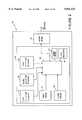
- FIG. 2is a block diagram of one embodiment of the computer input device of this invention.
- FIG. 3ais a drawing of the present system embodied in a mouse from the perspective showing a right-handed thumb location.
- FIG. 3bis a drawing of the present system embodied in a mouse from the perspective showing a left-handed thumb location.
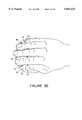
- FIG. 3cis a drawing of the present system embodied in a mouse and being operated by a user's left hand.
- FIG. 3dis an overhead view of the present system embodied in a mouse and operated by a user's right hand.
- FIG. 4ais an overhead view of the present system embodied in a trackball.
- FIG. 4bis a front view of the present system embodied in a trackball.
- FIG. 4cis a side view of the present system embodied in a trackball.
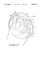
- FIG. 4dis an overhead view of the present system embodied in a trackball being operated by a user's left hand.
- FIG. 4eis an overhead view of the present system embodied in a trackball being operated by a user's right hand.
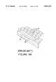
- FIG. 5ais a drawing of the computer input device embodied as extension from the keyboard without the present invention shown.
- FIG. 5bis a drawing of a left hand manipulating such an extension of FIG. 5a.
- FIG. 5cis a drawing of the present system embodied in a computer input device using the rod/stick extending from the keyboard and showing the placement of sensors.
- FIG. 5dis a drawing of the present system embodied in a computer input device of FIG. 5c with an alternate placement of the sensors.
- FIG. 5eis a drawing of a computer input device embodiment of the extending rod/stick with the outline of a user's right hand index finger shown manipulating the rod.
- FIG. 6ais a drawing of a driver/receiver and the return of a beam to the receiver when a thumb or other object is above the driver/receiver.
- FIG. 6bis a drawing of a driver/receiver and the reflection of the infrared beam when a thumb or other object is not above the driver/receiver pair.
- FIG. 7is a schematic diagram of an embodiment of the control circuit of this invention with one sensor.
- FIG. 8is a schematic diagram of an embodiment of the control circuit of this invention with two sensors.
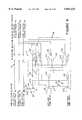
- FIG. 9is a schematic diagram of yet another embodiment of the control circuit of this invention with two sensors and circuitry to generate handedness and error signals.
- FIG. 10is a timing diagram showing the logic level of various signals in a typical control circuit at various time periods.
- FIG. 1illustrates a computer system 10 in which the present invention can be utilized.
- the present inventionis a computer input device, e.g., a mouse 30 coupled to a computer 12, wherein the computer input device 30 has an output for communicating with the computer 12.
- the computer input device 30comprises a shell or body designed with recesses for digits of the human hand on either side of an upwardly-sloping curvature for the other digits or fingers and the palm of a hand.
- the computer input device 30also a control circuit which includes one or more sensors together and a configuration circuit to automatically determine whether the user is operating the computer input device 30 with a right hand or a left hand and then to configure the selection actuators or buttons accordingly.
- the present inventionsolves the problem of having to either manually change the handedness of the input device 30 or to make handedness changes in the system software.
- the computer input device 30 of the present inventionis attached to a computer 12 via a serial port or a bus port.
- Monitor 14, hard and/or floppy disk drives 16, CD-ROM drives 18, and/or printer 11 or other peripherals, as well as other input devices, for example, a keyboard 20,are also operatively connected to the computer 12.
- the computer 12operates under the control of an operating system 24, which is represented in FIG. 1 by the display on the monitor 12.
- the operating system 24controls the actions of one or more application computer programs 26 executed by the computer 12.
- the computer input device 30is used by the operator to operate both the operating system 24 and the application computer programs 26.
- FIG. 2is a block diagram illustrating typical components of the computer input device 30.
- the computer input device 30includes an output transmitter 32 and a control circuit 34.
- the output transmitter 32may be a wire connecting the computer input device 30 to the computer, a wireless transmitter or any other means of sending a signal to the computer.
- the control circuit 34may include a left selection actuator 36, a middle selection actuator 38, and a right selection actuator 40.
- An example of a selection actuatoris a button on a mouse, a button on a trackball or a button on a keyboard computer input device such as a TRACKPOINT®.
- the control circuit 34also includes a first sensor 42 and a second sensor 44. Examples of such sensors are optical driver/receivers using infrared or visible light, piezoelectric transducers, touchplates, or a temperature or heat sensor.
- the control circuit 34also includes an electronic configuration circuit in conjunction with a sensor to automatically determine whether the user is operating the computer input device with a left hand or a right hand and then to configure the actuators to accommodate the handedness of the user.
- Configuration circuit 46receives signals from at least one of the sensors 42 and 44 and is electrically connected to the selection actuators and to the output transmitter 32.
- the control circuit 34includes a visual indicator 48 connected to the configuration circuit 46.
- the visual indicatormay be a light emitting diode typically located where it can be easily seen by the user.
- the visual indicator 48 shown in FIGS. 3a-dis located on the shell 58, substantially adjacent to the left selection actuator 36. If the computer input device 30 is not properly operated by the user's hand, then the visual indicator 48 is in one state, and if the computer input device 30 is properly operated by the user, then the visual indicator 48 is in a different state, such as "on” or "off” or blinking or variation in hue. Alternatively, the visual indicator 48 could be an indication on the computer display such as an icon, a message, or other marker.
- Control circuit 34may also include an audible indicator 50 which emits an audible sound to indicate handedness or to inform the user that the computer input device 30 is not being properly operated.
- the audible indicator 50might be a speaker coupled to the computer input device or coupled to the computer, and states of the sound means could be emitting sound, not emitting sound, different tones, verbal messages, etc.
- FIGS. 3a-dThe implementation of the invention in the form of a mouse 30 is shown in FIGS. 3a-d.
- a mouse 30includes a shell 58 and a spherical ball (not shown) between the shell and a supporting surface on which the mouse 30 can be operated.
- the mouse 30 in FIGS. 3a-dincludes a left selection actuator 36, a middle selection actuator 38, and a right selection actuator 40, although typically many mice have only a left selection actuator 36 and a right selection actuator 40.
- the invention hereinis intended to cover such a computer input device, regardless of the number of selection actuators.
- a mouse 30 or other input devicecan have any number of selection actuators.
- the selection actuators shown in FIGS. 3a-dare activated by being depressed downward into the shell 58 of the mouse.
- Each selection actuatorcorresponds to the communication of a unique signal to the computer.
- activation of left selection actuator 36could send a signal to the computer to select an icon on the display and activation of right selection actuator 40 could communicate a different signal to the computer.
- the activation of right selection actuator 40could tell the computer to display a menu.
- the mouse 30 shown in FIG. 3balso includes a wire 60, as an embodiment of output transmitter 32, connected to the computer (not shown) to relay signals from the computer input device to the computer.
- the mouse 30 shown in FIGS. 3a-dalso includes a first location 64 and a second location 62.
- the locations 62 and 64are not limited to a particular side of the mouse or to a particular digit of a hand, although mouse 30 is preferably designed so that thumbs recesses of the first and second locations 62 and 64; any finger or appendage or even a tool used to operate the mouse or computer input device 30.
- this descriptionwill treat the "first location" as the thumb location that receives the thumb of the user's left hand, and the "second thumb location” as the location that receives the thumb of the user's right hand.
- the locations 62 and 64are concavities of the shell 58 of the mouse.
- FIG. 3cshows the thumb of a user's left hand fitting into the first location 64.
- a thumb of the user's right handeasily fits into the second thumb location 62.
- the mouseis ergonomically shaped such that the user's hand naturally and comfortably holds the mouse when the user's thumb is located in the appropriate thumb location.
- the first or index, the second or middle, and third or ring fingersare situated over the selection actuators 36, 38, and 40.
- FIG. 3ashows a sensor 44 in the second location 62.
- Sensors 42 and 44are not restricted to one type of sensor used; in one embodiment, sensors 42 and 44 are infrared sensors, although sensors sensitive to other wavelengths of radiation would function as well.
- sensor 42senses the presence of the thumb.
- the presence of a thumb in the first location 64indicates that the user is operating the mouse with the left hand.
- the presence of a thumb in the second location 62indicates that the user is operating the mouse with the right hand.
- the control circuit 34deems the user to not be operating the computer input device properly. Additionally, if both sensor 42 and sensor 44 simultaneously sense the presence of an object such as a thumb or finger, then the control circuit 34 deems the user to not be operating the computer input device properly. In either case, an error signal is generated.
- the computer input device of this inventioncan also be implemented in the form of a trackball 150.
- FIGS. 4a-4eshow the computer input device as a trackball 150.
- An overhead view and a front view of an embodiment of the invention in a trackball 150is shown in FIGS. 4a and 4b respectively.
- the trackball 150has a shell 59 with a ball 132 partially extending spherically out from the shell (also see FIG. 4c). Movement of the ball 132 sends a positional signal to the computer; for example, the movement of the ball 132 moves the cursor on the computer display.
- the trackball 150 shown in the figureshas a left selection actuator 36 and a right selection actuator 40. Note, however, that the trackball 150 could have any number of selection actuators.
- the trackball 150has a right sensor 42 located in location 134 which might be a location for the right third finger, and the device has a left sensor 44 located in location 136 which might accommodate the left third finger. Note that the designation of the right and left sensors to any particular side of the trackball is for example only.
- Locations 134 and 136are concavities of the shell 59 to accommodate various fingers. Adjacent to location 134 is location 138 which might accommodate the right fourth or smallest finger. Adjacent to location 136 is yet another hollow location 140 which might accommodate the left fourth or smallest finger.
- Pad 142is that portion of this embodiment upon which the palm of the hand rests while operating the trackball.
- FIG. 4bshows a front view of the features mentioned above.
- FIG. 4dillustrates an embodiment of the trackball 150 being operated by the user's left hand.
- the user's first or index fingeris used to rotate the ball 132.
- the user's thumbis used to activate the right selection actuator 40, and the second or middle finger is used to activate the left selection actuator 36.
- the user's third fingerfits easily and naturally into location 136, thereby activating the left sensor 44.
- the user's fourth or smallest fingeris placed in location 140.
- the locations 138 and 140 illustrated hereindo not contain sensors. However, a sensor in one or both locations 138 and 140 is certainly within the coverage of the appended claims.
- FIG. 4eillustrates an embodiment of the trackball 150 being operated by the user's right hand.
- the user's first or index fingeroperates the ball 132
- the thumbactivates the left selection actuator 36
- the second or middle fingeractivates the right selection actuator 40.
- the user's third fingeris placed in location 134 where it activates the right sensor 42.
- the fourth or smallest finger of the user's right-handis positioned in location 138.
- the thumbbe used to activate the primary function and the second or middle finger to activate the secondary function. If the right sensor 42 is activated, then the user is operating the trackball 150 with the right hand and the right selection actuator 40 corresponds with the secondary function and the left selection actuator 36 corresponds with the primary function. If the left sensor 44 is activated, then the user is operating the trackball 150 with the left hand and the left selection actuator 36 corresponds with the secondary function and the right selection actuator 40 corresponds with the primary function.
- the trackball 150therefore, operates in the same way as the mouse, as described above, and can utilize the same control circuitry, as described later in this description.
- the computer input device of this inventioncan be implemented in a keyboard, an example of which is a TRACKPOINT®.
- FIG. 5ashows a portion of a keyboard including such a device without the present invention.
- a cylindrically-shaped rod 70is attached to the keyboard above the "B" key and between the "G" and “H” keys on the QWERTY layout of a keyboard.
- the usermanipulates the indicator or cursor on the computer display by applying pressure to the rod 70. For example, to move the cursor on the display, the user pushes the rod 70 away from the "B" key.
- the usertypically manipulates the rod 70 with the index finger of the right hand or the index finger of the left hand.
- FIG. 5aalso includes a right selection actuator 40 and a left selection actuator 36. These selection actuators perform the same function as selection actuators in other types of computer input devices.
- FIG. 5bshows a keyboard computer input device being operated with a user's left hand. The index finger of the user's left hand is manipulating the rod 70. The thumb of the user's left hand is on top of the right selection actuator 40. If the user operates the keyboard computer input device with a right hand, then the thumb of the right hand would be situated on top of the left selection actuator 36. Therefore, for a left-handed user of the rod 70, the right selection actuator 40 should correspond with the primary function, and the left selection actuator 36 should correspond with the secondary function. The opposite is true for a right-handed user of the rod 70.
- FIG. 5cillustrates one embodiment of the present invention in a keyboard computer input device.
- the letters “G”, “H”, “V”represent the keys on a standard QWERTY keyboard.
- the rod 70is fixed to the keyboard above the “B” key and between the “G” and “H” key.
- the "X” in FIG. 5crepresents a driver in an optical driver receiver pair, and the “O” represents a receiver.
- the first sensor 42 and the second sensor 44could be any sensor known by one skilled in the art which could sense the presence of a thumb or finger, such as a heat detector to detect body heat or other temperature greater than ambient temperature.
- FIG. 5dillustrates an alternate position for the driver and receiver of the first sensor 42 and the second sensor 44.
- FIG. 5edemonstrates how manipulation of the rod 70 with the index finger 130 of the user's right hand covers the second sensor 44 but not the first sensor 42. Likewise, if the user manipulates the rod 70 with the index finger of the left hand, then the first sensor 42 is covered but second sensor 44 is not covered.
- FIGS. 6a and 6bshow how the covering of an optical driver/receiver, by an index finger, results in detection or sensing of the finger.
- the user's finger surface 72is substantially directly above the driver 74 and the receiver 76 of the first sensor 42.
- the dotted line 71merely indicates the plane of upper surface of the keys when a key is depressed.
- a lens(not shown) might be inserted at this depth to facilitate the invention.
- the driver 74emits an infrared beam which reflects off the thumb or finger surface 72 to the receiver 76. If the thumb or finger surface is not above the driver 74 and receiver 76, as shown in FIG. 6b, then the infrared beam will not directly reflect back to the receiver 76 and the sensor is not activated.
- Control circuits of the present inventioncomprise not only at least one sensor, such as sensor 42, but also a configuration circuit 46 for automatically determining handedness, i.e., whether the user is operating the computer input device with a left hand or a right hand, either by directly sensing an object, such as a thumb or finger, or the absence of the object.
- the key feature of the control circuitis that the computer input device determines handedness independent of the computer and/or its software.
- the control circuitfurther configures the primary and secondary functions of the selection actuators for a particular handedness.
- FIG. 7is a schematic diagram of one embodiment of the control circuit 34 of this invention which, given the output of a single sensor, will configure the selection actuators to primary and secondary functions.
- the control circuitcomprises a first sensor 42 and the configuration circuit 46.
- the configuration circuit 46further comprises AND gates 78, 80, 84 and 88; OR gates 82 and 86; and an invertor 90.
- the left selection actuator input 36, middle selection actuator input 38, and right selection actuator input 40are the same as the left selection actuator output 96, middle selection actuator output 94 and the right selection actuator output 92 respectively.
- the configuration circuit 46may alter these connections depending upon whether the sensor 42 is activated.
- signal Dis high. If the thumb of the user's left hand is located in the first location 64 shown in FIG. 3c, signal D is high. If the user then activates the left selection actuator 36, then signal A is high. This means that both inputs to AND gate 78 are high and, therefore, signal J is high. Since at least one of the inputs to OR gate 82 is high, the output, signal E, is also high. Signal E is the same as the right selection actuator output 92. Therefore signal A, which was high on the left selection actuator 36, has now become a high signal E on the right selection actuator output 92. Therefore, the activation of the sensor 42 by an object causes the configuration circuit 46 to determine that the mouse is a left-handed mouse and that the right selection actuator 40 is to be associated with a primary function and the left selection actuator 36 is to be associated with a secondary function.
- the inventiondetermines that the mouse is a right-handed mouse and that the left selection actuator 36 is associated with a primary function and the right selection actuator 40 is associated with a secondary function. Note that the signal B on the middle selection actuator input 38 is the same as the middle selection actuator output 94. The middle selection actuator output 94 is not affected by the state of the left-handed thumb sensor 42.
- the schematic diagram in FIG. 8is an embodiment of the control circuit with a first sensor 42, a second sensor 44, and a configuration circuit 46.
- the inventionin this embodiment of FIG. 8, directly detects a thumb or finger, by first sensor 42 or second sensor 44, and once that thumb or finger is sensed by a particular sensor, the configuration circuit 46 operates to configure the selection actuators. So, for purposes of discussion only, first sensor 42 will be referred to as the left-handed thumb sensor 42, and the second sensor 44 will be referred to as the right-handed thumb sensor 44, but the terms "first sensor” and "second sensor” in the claims is not limited to a particular side of the computer input device.
- the signal Dis high and the signal L is low. If only the left selection actuator 36 is activated, the signal A is high. Because only one of signals D and L are high, the output of the exclusive OR gate 98, signal M, is high. Signal M and signal D, both high, are fed into AND gate 100, resulting in a high signal O. The high signal O and the high signal A are input into the AND gate 106, resulting in a high signal S and, therefore, a high signal U. The end result is that, when the operator is operating the mouse with the left hand and the left selection actuator is activated, then the high signal A from the left selection actuator 36 becomes the high signal U, which is the same as the right selection actuator output 92.
- signal Qis high, as is signal R. Accordingly, the high signal C from the activation of the right selection actuator 40 results in a high signal R which is the left selection actuator output 96. Therefore, when the computer input device 30 is operated with a left hand, the configuration circuit 46 switches the operation of the left and right selection actuators so that they are optimized to operate with the user's left hand.
- the middle selection actuator 38With regard to the middle selection actuator 38, signal M, which is high, is input to AND gate 104 along with signal B. The resulting signal V, therefore, tracks signal B. Activation of the middle selection actuator 38, therefore, creates a high signal V, which is the middle selection actuator output 94. Note, however, that if the mouse is not operated properly, i.e., neither the left-handed thumb sensor 42 nor the right-handed thumb sensor 44 are activated or both are activated at the same time, then the signal M is low, and activation of any selection actuators results in no outputs (92, 94 or 96).
- the circuit shown schematically in FIG. 8behaves as follows: signals D and L, which are both low, feed into the exclusive OR gate 98. Therefore, the output of the exclusive OR gate 98, signal M, is low. Signal M is input into AND gates 100, 102, and 104. Therefore, signals N, O and V, the outputs of these AND gates, are all low. Because the signals N and O feed into all of the remaining AND gates 106, 110, 112, 116, the signals U and R are also low. The result is that the left selection actuator output 96, the middle selection actuator output 94, and the right selection actuator output 92 are all low. In general terms, if both thumb sensors are sensing a thumb or finger, then the control circuit prevents the signals from the selection actuators from being transmitted to the computer.
- Lastis the fourth scenario in which neither the left-handed thumb sensor 42 nor the right-handed thumb sensor 44 sense a thumb or a finger. Again, because signals D and L are input into the exclusive OR gate 98, signal M is low. Therefore, the result is the same as in the case of activation of both sensors, i.e., the left, middle and right selection actuator outputs 96, 94 and 92 are low regardless of whether the selection actuators are activated.
- FIG. 9Another embodiment of the control circuit is shown schematically in FIG. 9. This embodiment is the same as the embodiment shown in FIG. 8 but with the addition of circuitry to the control circuit to support the light emitting diode or other visual indicator 48 and the sound means 50. If only one of the left-handed thumb sensor 42 and the right-handed thumb sensor 44 are activated, then the mouse is being operated properly, and the exclusive OR gate 98 has output signal M which is high. Signal M is input to inverter 118 such that signal W is low. The output of inverter 118 is connected to the light emitting diode 48. The opposite end of light emitting diode 48 is connected to resistor 120, which in turn is connected to voltage source 128. Because signal W is low, current flows from the voltage source 128 through the resistor 120 and to the visual indicator 48. Alternatively, a signal could be output to the computer to be interactive with software and either an icon or other visual message could appear on the display to indicate handedness.
- the visual indicator 48is not lit.
- the circuitcan be configured so that if the visual indicator or light emitting diode is lit, it means that the mouse is not being properly operated. In such a case, the left-handed thumb sensor 42 and the right-handed thumb sensor 44 are both activated or neither is activated, and the output of the exclusive OR gate 98, signal M, is low. The result is that signal W is high and no signal is output to the visual indicator 48.
- the sound generator 128can be either incorporated into the mouse or keyboard unit, or the signal can be output to the computer to interact with the software and emit tones or audible messages indicating handedness or that an error condition exists.
- FIG. 10is a timing diagram for the circuit shown in FIG. 9.
- signal Zis the input to the sound generator 128.
- a high on signal Zactivates the sound generator 128.
- the signal X and signal Ware both low.
- the right-handed thumb sensor 44is activated and the left-handed thumb sensor 42 is not activated. In other words, the user is using the right hand to operate the computer input device 30.
- the resultis that the control circuit does not switch the operation of the selection actuators.
- Left selection actuator 36is activated during t3, and the result is a corresponding high signal on the left selection actuator output 96.
- the middle selection actuator 38 and the right selection actuator 40are activated at different times. The result is a high signal on the middle selection actuator output 94 during the activation of the middle selection actuator 38, and a high signal on the right selection actuator output 92 during the activation of the right selection actuator 40.
- control circuitcould be implemented with different circuitry or in software.
Landscapes
- Engineering & Computer Science (AREA)
- General Engineering & Computer Science (AREA)
- Theoretical Computer Science (AREA)
- Human Computer Interaction (AREA)
- Physics & Mathematics (AREA)
- General Physics & Mathematics (AREA)
- Position Input By Displaying (AREA)
Abstract
Description
Claims (25)
Priority Applications (1)
| Application Number | Priority Date | Filing Date | Title |
|---|---|---|---|
| US08/688,972US5841425A (en) | 1996-07-31 | 1996-07-31 | Ambidextrous computer input device |
Applications Claiming Priority (1)
| Application Number | Priority Date | Filing Date | Title |
|---|---|---|---|
| US08/688,972US5841425A (en) | 1996-07-31 | 1996-07-31 | Ambidextrous computer input device |
Publications (1)
| Publication Number | Publication Date |
|---|---|
| US5841425Atrue US5841425A (en) | 1998-11-24 |
Family
ID=24766550
Family Applications (1)
| Application Number | Title | Priority Date | Filing Date |
|---|---|---|---|
| US08/688,972Expired - LifetimeUS5841425A (en) | 1996-07-31 | 1996-07-31 | Ambidextrous computer input device |
Country Status (1)
| Country | Link |
|---|---|
| US (1) | US5841425A (en) |
Cited By (79)
| Publication number | Priority date | Publication date | Assignee | Title |
|---|---|---|---|---|
| US5977952A (en)* | 1997-10-29 | 1999-11-02 | International Business Machines Corporation | Method and system for an ambidextrous mouse |
| US6005553A (en)* | 1995-08-09 | 1999-12-21 | Midas Mouse International Pty. Ltd. | Ergonomic computer mouse |
| US6034627A (en)* | 1998-02-19 | 2000-03-07 | Wei; Meng-Yu | Computer input device |
| US6072471A (en)* | 1997-09-17 | 2000-06-06 | Lo; Jack | Ambidextrous upright computer mouse |
| US6093159A (en)* | 1998-03-16 | 2000-07-25 | Racoosin; Eric A. | Freely rotational manual body massager |
| WO2000079511A1 (en)* | 1999-06-24 | 2000-12-28 | Adelbert Timothy Czapp | Ergonomic computer mouse with redundancy features |
| WO2001050449A1 (en)* | 1999-12-31 | 2001-07-12 | Ergodevices Corporation | An ergonomic dual-section computer-pointing device |
| US20010011995A1 (en)* | 1998-09-14 | 2001-08-09 | Kenneth Hinckley | Method for providing feedback responsive to sensing a physical presence proximate to a control of an electronic device |
| US20010015718A1 (en)* | 1998-09-14 | 2001-08-23 | Hinckley Kenneth P. | Method for displying information responsive to sensing a physical presence proximate to a computer input device |
| WO2001014956A3 (en)* | 1999-08-24 | 2001-08-30 | Cyclus Inc | Virtual desktop system and method |
| US6333753B1 (en) | 1998-09-14 | 2001-12-25 | Microsoft Corporation | Technique for implementing an on-demand display widget through controlled fading initiated by user contact with a touch sensitive input device |
| US6359611B2 (en)* | 1998-05-20 | 2002-03-19 | Kwan-Ho Chan | Finger controlled computer mouse |
| US20020036660A1 (en)* | 1998-09-14 | 2002-03-28 | Adan Manolito E. | Input device with forward/backward control |
| DE10049411A1 (en)* | 2000-10-05 | 2002-04-18 | Siemens Ag | Hand-held device such as a mobile phone, PDA, palmtop, hand- held PC, etc. with left or right-hand operation recognition to make use of such devices easier for left handed persons |
| US6396477B1 (en) | 1998-09-14 | 2002-05-28 | Microsoft Corp. | Method of interacting with a computer using a proximity sensor in a computer input device |
| US6417843B1 (en)* | 1998-05-11 | 2002-07-09 | Logitech Europe S.A. | Mouse with cushioning pads |
| WO2002061673A1 (en)* | 2001-02-02 | 2002-08-08 | Zygnoph Aps | A computer mouse, a method of monitoring usage of a computer mouse and a method for determining the status of a combined left- and right-handed computer mouse |
| US20020126088A1 (en)* | 2001-03-08 | 2002-09-12 | International Business Machines Corporation | User interactive cursor control in a computer controlled display system with supplemental mouse lighting to aid in cursor positioning |
| US6456275B1 (en) | 1998-09-14 | 2002-09-24 | Microsoft Corporation | Proximity sensor in a computer input device |
| WO2002093466A1 (en)* | 2001-05-15 | 2002-11-21 | Robert Bosch Gmbh | Device equipped with a sensor |
| US6486873B1 (en) | 2000-04-06 | 2002-11-26 | Microsoft Corporation | Illuminated computer input device |
| US6489947B2 (en) | 1997-08-15 | 2002-12-03 | Ergodevices Corp. | Ergonomic dual-section computer-pointing device |
| US20030006965A1 (en)* | 2001-07-06 | 2003-01-09 | Bohn David D. | Method and apparatus for indicating an operating mode of a computer-pointing device |
| US6538636B1 (en) | 1999-07-06 | 2003-03-25 | Intel Corporation | Apparatus and method for configuring a hand-held interactive device |
| US20030160764A1 (en)* | 2002-02-26 | 2003-08-28 | Yen-Liang Kuan | Power saving device |
| US6646626B1 (en)* | 1999-11-01 | 2003-11-11 | Motorola, Inc. | Method and apparatus for automatic viewing angle adjustment for liquid crystal display |
| US6664947B1 (en)* | 1999-02-24 | 2003-12-16 | Gueorgui K. Vinogradov | Safe and handy pointing device |
| US6677927B1 (en)* | 1999-08-23 | 2004-01-13 | Microsoft Corporation | X-Y navigation input device |
| US6693648B1 (en)* | 2000-11-22 | 2004-02-17 | Campus Crusade For Christ, Inc. | Pointer interactive apparatus |
| US20040035876A1 (en)* | 2002-08-23 | 2004-02-26 | Pfizer Inc | Apparatus for dispensing articles |
| WO2003077110A3 (en)* | 2002-03-13 | 2004-09-23 | Welbergen Beheer B V | System for providing an input signal, device for use in such a system and computer input device |
| NL1023173C2 (en)* | 2003-04-14 | 2004-10-18 | Cornelis Arnoldus Ma Verspagen | Ergonomic computer mouse is for exchange effects with computer and comprises housing and at least one mainly flat support side which in use supports housing on base |
| US6828958B2 (en) | 2000-02-14 | 2004-12-07 | Anthony G. Davenport | Ergonomic side grip computer mouse |
| US20040246231A1 (en)* | 2003-06-03 | 2004-12-09 | Thomas Large | Biomechanically low load computer mouse |
| US20050007345A1 (en)* | 2002-02-26 | 2005-01-13 | Yen-Liang Kuan | Power saving device |
| US20050030278A1 (en)* | 2003-08-08 | 2005-02-10 | Liang Fu | Adjustable pointing and control device with automatic handedness switch |
| US20050030285A1 (en)* | 2003-08-08 | 2005-02-10 | Liang Fu | Sensor controls for pointing and control device and such device |
| US20050057505A1 (en)* | 2002-06-03 | 2005-03-17 | Kokuyo Co., Ltd. | Mouse |
| US6937225B1 (en)* | 2000-05-15 | 2005-08-30 | Logitech Europe S.A. | Notification mechanisms on a control device |
| US20050206619A1 (en)* | 1999-04-06 | 2005-09-22 | Microsoft Corporation | Computer input device with digit support and natural position actuators |
| US20060016966A1 (en)* | 2004-07-22 | 2006-01-26 | Hughes Michael R | Input devices for control of airborne camera systems |
| US20060038774A1 (en)* | 2004-08-20 | 2006-02-23 | Mese John C | System and method for automatically establishing handedness settings of embedded input device |
| US20060038780A1 (en)* | 2004-08-20 | 2006-02-23 | Mese John C | System and method for automatically establishing handedness settings of mouse-like input device |
| US7006075B1 (en) | 1997-11-10 | 2006-02-28 | Micron Technology Inc. | Ergonomic computer mouse |
| US20060197750A1 (en)* | 2005-03-04 | 2006-09-07 | Apple Computer, Inc. | Hand held electronic device with multiple touch sensing devices |
| US7113171B2 (en) | 1997-06-10 | 2006-09-26 | Mark Vayda | Universal input device |
| US20060250364A1 (en)* | 2005-05-09 | 2006-11-09 | Alex Gorbunov | Ergonomic computer mouse |
| US20070080945A1 (en)* | 2002-05-28 | 2007-04-12 | Apple Computer, Inc. | Mouse having a button-less panning and scrolling switch |
| US20070216647A1 (en)* | 2006-03-17 | 2007-09-20 | Hon Hai Precision Industry Co., Ltd. | Left/right hand operated sensing intelligent mouse |
| US20070279381A1 (en)* | 2006-06-01 | 2007-12-06 | Microsoft Corporation Microsoft Patent Group | Ergonomic input device |
| US7358963B2 (en) | 2002-09-09 | 2008-04-15 | Apple Inc. | Mouse having an optically-based scrolling feature |
| US20080106515A1 (en)* | 2006-11-08 | 2008-05-08 | Denso Corporation | Operation apparatus |
| US7385587B1 (en)* | 1999-09-24 | 2008-06-10 | Lenovo (Singapore) Pte. Ltd. | Asymmetrical computer mouse design with extended thumb button |
| US20080143670A1 (en)* | 1997-06-10 | 2008-06-19 | Mark Vayda | Universal input device and system |
| US20080211667A1 (en)* | 2004-10-05 | 2008-09-04 | Broadcom Corporation | Wireless human interface device with integrated temperature sensor |
| EP1971117A1 (en)* | 2006-03-31 | 2008-09-17 | T & A Mobile Phones Limited | Mobile phone with sensor for detection of user's handling |
| US20080297476A1 (en)* | 2003-09-02 | 2008-12-04 | Steve Hotelling | Ambidextrous Mouse |
| US20090046064A1 (en)* | 2007-08-17 | 2009-02-19 | Microsoft Corporation | Pointing device for control of a graphical display or application |
| US20090146955A1 (en)* | 2007-12-08 | 2009-06-11 | Duc Phu Truong | Mouse with a finger triggered sensor |
| US7710397B2 (en) | 2005-06-03 | 2010-05-04 | Apple Inc. | Mouse with improved input mechanisms using touch sensors |
| US20100156791A1 (en)* | 2008-12-18 | 2010-06-24 | Silitek Electronic (Guangzhou) Co., Ltd. | Temperature controlled mouse |
| US20100199124A1 (en)* | 2009-01-30 | 2010-08-05 | Honeywell International Inc. | Systems and methods for reconfiguring input devices |
| USD622405S1 (en)* | 2010-03-17 | 2010-08-24 | Sanjeev Tuli | Foot sole massager |
| US8013840B1 (en)* | 2000-04-06 | 2011-09-06 | Microsoft Corporation | User notification system with an illuminated computer input device |
| US8077147B2 (en) | 2005-12-30 | 2011-12-13 | Apple Inc. | Mouse with optical sensing surface |
| US20110310017A1 (en)* | 2010-06-18 | 2011-12-22 | Hon Hai Precision Industry Co., Ltd. | Computer system, mouse, and automatically shifting method thereof |
| US20120086639A1 (en)* | 2010-10-07 | 2012-04-12 | Hon Hai Precision Industry Co., Ltd. | Computer mouse and method thereof |
| US20130027334A1 (en)* | 2011-07-28 | 2013-01-31 | Kabushiki Kaisha Toshiba | Information input device, information input device control method, and computer readable medium |
| KR101250961B1 (en)* | 2011-03-07 | 2013-04-04 | (주) 더블유글로벌 | Ergonomic mouse for selecting left or right hand automatically |
| US8654524B2 (en) | 2009-08-17 | 2014-02-18 | Apple Inc. | Housing as an I/O device |
| CN103809777A (en)* | 2012-11-15 | 2014-05-21 | 和硕联合科技股份有限公司 | Multifunctional input device |
| US9047009B2 (en) | 2005-03-04 | 2015-06-02 | Apple Inc. | Electronic device having display and surrounding touch sensitive bezel for user interface and control |
| US20150370362A1 (en)* | 2010-11-10 | 2015-12-24 | Lenovo (Singapore) Pte. Ltd. | Sensor control |
| US9268390B2 (en) | 2010-12-14 | 2016-02-23 | Microsoft Technology Licensing, Llc | Human presence detection |
| US9851883B2 (en)* | 2014-02-17 | 2017-12-26 | Xerox Corporation | Method and apparatus for adjusting and moving a user interface for single handed use on an endpoint device |
| CN110462259A (en)* | 2016-11-29 | 2019-11-15 | 虚拟切割有限公司 | User controller with user presence detection and related systems and methods |
| US10599233B1 (en)* | 2019-03-01 | 2020-03-24 | Alfaisal University | Computer mouse device with modified design and functionality |
| US11275405B2 (en) | 2005-03-04 | 2022-03-15 | Apple Inc. | Multi-functional hand-held device |
| US11442557B2 (en)* | 2009-06-12 | 2022-09-13 | Steelseries Aps | Navigation device and methods thereof |
Citations (10)
| Publication number | Priority date | Publication date | Assignee | Title |
|---|---|---|---|---|
| US4939508A (en)* | 1988-10-31 | 1990-07-03 | Emtek Health Care Systems, Inc. | Point and select device |
| US5006836A (en)* | 1988-06-14 | 1991-04-09 | Wang Laboratories, Inc. | Squeezable computer control device |
| US5122785A (en)* | 1988-11-14 | 1992-06-16 | Wang Laboratories, Inc. | Squeezable control device for computer display system |
| US5186629A (en)* | 1991-08-22 | 1993-02-16 | International Business Machines Corporation | Virtual graphics display capable of presenting icons and windows to the blind computer user and method |
| US5287090A (en)* | 1992-09-30 | 1994-02-15 | Grant Alan H | Combination mouse and track ball unit |
| US5298919A (en)* | 1991-08-02 | 1994-03-29 | Multipoint Technology Corporation | Multi-dimensional input device |
| US5301222A (en)* | 1990-01-24 | 1994-04-05 | Nec Corporation | Portable radio telephone set for generating pattern signals representative of alphanumeric letters indicative of a telephone number |
| US5382962A (en)* | 1993-01-11 | 1995-01-17 | Young; Edgar D. | Dual purpose handle and controller for handheld computer |
| US5432510A (en)* | 1993-03-22 | 1995-07-11 | Matthews; Walter S. | Ambidextrous single hand chordic data management device |
| US5648798A (en)* | 1995-02-13 | 1997-07-15 | Hamling; Daniel T. | Universal ergonomic computer mouse/trackball |
- 1996
- 1996-07-31USUS08/688,972patent/US5841425A/ennot_activeExpired - Lifetime
Patent Citations (10)
| Publication number | Priority date | Publication date | Assignee | Title |
|---|---|---|---|---|
| US5006836A (en)* | 1988-06-14 | 1991-04-09 | Wang Laboratories, Inc. | Squeezable computer control device |
| US4939508A (en)* | 1988-10-31 | 1990-07-03 | Emtek Health Care Systems, Inc. | Point and select device |
| US5122785A (en)* | 1988-11-14 | 1992-06-16 | Wang Laboratories, Inc. | Squeezable control device for computer display system |
| US5301222A (en)* | 1990-01-24 | 1994-04-05 | Nec Corporation | Portable radio telephone set for generating pattern signals representative of alphanumeric letters indicative of a telephone number |
| US5298919A (en)* | 1991-08-02 | 1994-03-29 | Multipoint Technology Corporation | Multi-dimensional input device |
| US5186629A (en)* | 1991-08-22 | 1993-02-16 | International Business Machines Corporation | Virtual graphics display capable of presenting icons and windows to the blind computer user and method |
| US5287090A (en)* | 1992-09-30 | 1994-02-15 | Grant Alan H | Combination mouse and track ball unit |
| US5382962A (en)* | 1993-01-11 | 1995-01-17 | Young; Edgar D. | Dual purpose handle and controller for handheld computer |
| US5432510A (en)* | 1993-03-22 | 1995-07-11 | Matthews; Walter S. | Ambidextrous single hand chordic data management device |
| US5648798A (en)* | 1995-02-13 | 1997-07-15 | Hamling; Daniel T. | Universal ergonomic computer mouse/trackball |
Cited By (150)
| Publication number | Priority date | Publication date | Assignee | Title |
|---|---|---|---|---|
| US6005553A (en)* | 1995-08-09 | 1999-12-21 | Midas Mouse International Pty. Ltd. | Ergonomic computer mouse |
| US6124846A (en)* | 1995-08-09 | 2000-09-26 | Midas Mouse International Pty. Ltd. | Pointing device with ergonomic features |
| US7965279B2 (en)* | 1997-06-10 | 2011-06-21 | Mark Vayda | Universal input device and system |
| US20070165000A1 (en)* | 1997-06-10 | 2007-07-19 | Mark Vayda | Universal Input Device and System |
| US20080143670A1 (en)* | 1997-06-10 | 2008-06-19 | Mark Vayda | Universal input device and system |
| US7113171B2 (en) | 1997-06-10 | 2006-09-26 | Mark Vayda | Universal input device |
| US8279169B2 (en)* | 1997-06-10 | 2012-10-02 | Mark Vayda | Universal input device and system |
| US6489947B2 (en) | 1997-08-15 | 2002-12-03 | Ergodevices Corp. | Ergonomic dual-section computer-pointing device |
| US6072471A (en)* | 1997-09-17 | 2000-06-06 | Lo; Jack | Ambidextrous upright computer mouse |
| US5977952A (en)* | 1997-10-29 | 1999-11-02 | International Business Machines Corporation | Method and system for an ambidextrous mouse |
| US7701443B2 (en) | 1997-11-10 | 2010-04-20 | Micron Technology, Inc. | Ergonomic computer mouse |
| US7006075B1 (en) | 1997-11-10 | 2006-02-28 | Micron Technology Inc. | Ergonomic computer mouse |
| US20060139331A1 (en)* | 1997-11-10 | 2006-06-29 | Joshua Olson | Ergonomic computer mouse |
| US6034627A (en)* | 1998-02-19 | 2000-03-07 | Wei; Meng-Yu | Computer input device |
| US6093159A (en)* | 1998-03-16 | 2000-07-25 | Racoosin; Eric A. | Freely rotational manual body massager |
| US6417843B1 (en)* | 1998-05-11 | 2002-07-09 | Logitech Europe S.A. | Mouse with cushioning pads |
| US6359611B2 (en)* | 1998-05-20 | 2002-03-19 | Kwan-Ho Chan | Finger controlled computer mouse |
| US7256770B2 (en) | 1998-09-14 | 2007-08-14 | Microsoft Corporation | Method for displaying information responsive to sensing a physical presence proximate to a computer input device |
| US6559830B1 (en) | 1998-09-14 | 2003-05-06 | Microsoft Corporation | Method of interacting with a computer using a proximity sensor in a computer input device |
| US6396477B1 (en) | 1998-09-14 | 2002-05-28 | Microsoft Corp. | Method of interacting with a computer using a proximity sensor in a computer input device |
| US6456275B1 (en) | 1998-09-14 | 2002-09-24 | Microsoft Corporation | Proximity sensor in a computer input device |
| US7283121B2 (en) | 1998-09-14 | 2007-10-16 | Microsoft Corporation | Input device with forward/backward control |
| US20060050057A1 (en)* | 1998-09-14 | 2006-03-09 | Microsoft Corporation | Input device with forward/backward control |
| US20020054023A1 (en)* | 1998-09-14 | 2002-05-09 | Adan Manolito E. | Input device with forward/backward control |
| US7358956B2 (en) | 1998-09-14 | 2008-04-15 | Microsoft Corporation | Method for providing feedback responsive to sensing a physical presence proximate to a control of an electronic device |
| US20010011995A1 (en)* | 1998-09-14 | 2001-08-09 | Kenneth Hinckley | Method for providing feedback responsive to sensing a physical presence proximate to a control of an electronic device |
| US7602382B2 (en) | 1998-09-14 | 2009-10-13 | Microsoft Corporation | Method for displaying information responsive to sensing a physical presence proximate to a computer input device |
| US20060038786A1 (en)* | 1998-09-14 | 2006-02-23 | Microsoft Corporation | Input device with forward/backward control |
| US20010015718A1 (en)* | 1998-09-14 | 2001-08-23 | Hinckley Kenneth P. | Method for displying information responsive to sensing a physical presence proximate to a computer input device |
| US9069395B2 (en) | 1998-09-14 | 2015-06-30 | Microsoft Technology Licensing, Llc | Input device with forward/backward control |
| US20050088414A1 (en)* | 1998-09-14 | 2005-04-28 | Microsoft Corporation | Input device with forward/backward control |
| US20020036660A1 (en)* | 1998-09-14 | 2002-03-28 | Adan Manolito E. | Input device with forward/backward control |
| US7656389B2 (en) | 1998-09-14 | 2010-02-02 | Microsoft Corporation | Input device with forward/backward control |
| US7639235B2 (en) | 1998-09-14 | 2009-12-29 | Microsoft Corporation | Input device with forward/backward control |
| US6333753B1 (en) | 1998-09-14 | 2001-12-25 | Microsoft Corporation | Technique for implementing an on-demand display widget through controlled fading initiated by user contact with a touch sensitive input device |
| US6664947B1 (en)* | 1999-02-24 | 2003-12-16 | Gueorgui K. Vinogradov | Safe and handy pointing device |
| US20050206619A1 (en)* | 1999-04-06 | 2005-09-22 | Microsoft Corporation | Computer input device with digit support and natural position actuators |
| US7002552B1 (en)* | 1999-04-06 | 2006-02-21 | Microsoft Corporation | Computer input device with digit support and natural position actuators |
| US7345674B2 (en) | 1999-04-06 | 2008-03-18 | Microsoft Corporation | Computer input device with digit support and natural position actuators |
| WO2000079511A1 (en)* | 1999-06-24 | 2000-12-28 | Adelbert Timothy Czapp | Ergonomic computer mouse with redundancy features |
| US6538636B1 (en) | 1999-07-06 | 2003-03-25 | Intel Corporation | Apparatus and method for configuring a hand-held interactive device |
| US6677927B1 (en)* | 1999-08-23 | 2004-01-13 | Microsoft Corporation | X-Y navigation input device |
| WO2001014956A3 (en)* | 1999-08-24 | 2001-08-30 | Cyclus Inc | Virtual desktop system and method |
| US7385587B1 (en)* | 1999-09-24 | 2008-06-10 | Lenovo (Singapore) Pte. Ltd. | Asymmetrical computer mouse design with extended thumb button |
| US6646626B1 (en)* | 1999-11-01 | 2003-11-11 | Motorola, Inc. | Method and apparatus for automatic viewing angle adjustment for liquid crystal display |
| WO2001050449A1 (en)* | 1999-12-31 | 2001-07-12 | Ergodevices Corporation | An ergonomic dual-section computer-pointing device |
| US6828958B2 (en) | 2000-02-14 | 2004-12-07 | Anthony G. Davenport | Ergonomic side grip computer mouse |
| US8279177B2 (en) | 2000-04-06 | 2012-10-02 | Microsoft Corporation | User notification system with an illuminated computer input device |
| US8013840B1 (en)* | 2000-04-06 | 2011-09-06 | Microsoft Corporation | User notification system with an illuminated computer input device |
| US8629838B2 (en) | 2000-04-06 | 2014-01-14 | Microsoft Corporation | User notification system with an illuminated computer input device |
| US6486873B1 (en) | 2000-04-06 | 2002-11-26 | Microsoft Corporation | Illuminated computer input device |
| US6937225B1 (en)* | 2000-05-15 | 2005-08-30 | Logitech Europe S.A. | Notification mechanisms on a control device |
| DE10049411A1 (en)* | 2000-10-05 | 2002-04-18 | Siemens Ag | Hand-held device such as a mobile phone, PDA, palmtop, hand- held PC, etc. with left or right-hand operation recognition to make use of such devices easier for left handed persons |
| US6693648B1 (en)* | 2000-11-22 | 2004-02-17 | Campus Crusade For Christ, Inc. | Pointer interactive apparatus |
| WO2002061673A1 (en)* | 2001-02-02 | 2002-08-08 | Zygnoph Aps | A computer mouse, a method of monitoring usage of a computer mouse and a method for determining the status of a combined left- and right-handed computer mouse |
| US20020126088A1 (en)* | 2001-03-08 | 2002-09-12 | International Business Machines Corporation | User interactive cursor control in a computer controlled display system with supplemental mouse lighting to aid in cursor positioning |
| US6819313B2 (en)* | 2001-03-08 | 2004-11-16 | International Business Machines Corporation | User interactive cursor control in a computer controlled display system with supplemental mouse lighting to aid in cursor positioning |
| US20040021634A1 (en)* | 2001-05-15 | 2004-02-05 | Steffen Leutz | Device equipped with a sensor |
| WO2002093466A1 (en)* | 2001-05-15 | 2002-11-21 | Robert Bosch Gmbh | Device equipped with a sensor |
| US7024784B2 (en) | 2001-05-15 | 2006-04-11 | Robert Bosch Gmbh | Device equipped with a sensor |
| US7071920B2 (en)* | 2001-07-06 | 2006-07-04 | Hewlett-Packard Development Company, L.P. | Method and apparatus for indicating an operating mode of a computer-pointing device |
| US20030006965A1 (en)* | 2001-07-06 | 2003-01-09 | Bohn David D. | Method and apparatus for indicating an operating mode of a computer-pointing device |
| WO2003010633A3 (en)* | 2001-07-26 | 2009-06-11 | Good Work Systems | Ergonomic side grip computer mouse |
| US20030160764A1 (en)* | 2002-02-26 | 2003-08-28 | Yen-Liang Kuan | Power saving device |
| US20050007345A1 (en)* | 2002-02-26 | 2005-01-13 | Yen-Liang Kuan | Power saving device |
| RU2325687C2 (en)* | 2002-03-13 | 2008-05-27 | Ховерстоп Холдинг Б.В. | System for creating input signal, device for application in such system, and computer input device |
| WO2003077110A3 (en)* | 2002-03-13 | 2004-09-23 | Welbergen Beheer B V | System for providing an input signal, device for use in such a system and computer input device |
| CN100371868C (en)* | 2002-03-13 | 2008-02-27 | 后沃斯道·后丁公司 | System for providing an input signal, device for use in such a system and computer input device |
| US20070080945A1 (en)* | 2002-05-28 | 2007-04-12 | Apple Computer, Inc. | Mouse having a button-less panning and scrolling switch |
| US20050057505A1 (en)* | 2002-06-03 | 2005-03-17 | Kokuyo Co., Ltd. | Mouse |
| US9983742B2 (en) | 2002-07-01 | 2018-05-29 | Apple Inc. | Electronic device having display and surrounding touch sensitive bezel for user interface and control |
| US20040035876A1 (en)* | 2002-08-23 | 2004-02-26 | Pfizer Inc | Apparatus for dispensing articles |
| US7358963B2 (en) | 2002-09-09 | 2008-04-15 | Apple Inc. | Mouse having an optically-based scrolling feature |
| US8314773B2 (en) | 2002-09-09 | 2012-11-20 | Apple Inc. | Mouse having an optically-based scrolling feature |
| NL1023173C2 (en)* | 2003-04-14 | 2004-10-18 | Cornelis Arnoldus Ma Verspagen | Ergonomic computer mouse is for exchange effects with computer and comprises housing and at least one mainly flat support side which in use supports housing on base |
| WO2005001746A3 (en)* | 2003-06-03 | 2005-12-29 | Large Thomas | Biomechanically low load computer mouse |
| US7145548B2 (en)* | 2003-06-03 | 2006-12-05 | Torbay Holdings | Biomechanically low load computer mouse |
| EP1642259A4 (en)* | 2003-06-03 | 2006-08-23 | Thomas Large | Biomechanically low load computer mouse |
| US20040246231A1 (en)* | 2003-06-03 | 2004-12-09 | Thomas Large | Biomechanically low load computer mouse |
| US7109972B2 (en) | 2003-08-08 | 2006-09-19 | Liang Fu | Adjustable pointing and control device with automatic handedness switch |
| US20050030285A1 (en)* | 2003-08-08 | 2005-02-10 | Liang Fu | Sensor controls for pointing and control device and such device |
| US7212190B2 (en) | 2003-08-08 | 2007-05-01 | Liang Fu | Sensor controls for pointing and control device and such device |
| US20050030278A1 (en)* | 2003-08-08 | 2005-02-10 | Liang Fu | Adjustable pointing and control device with automatic handedness switch |
| US8537115B2 (en) | 2003-09-02 | 2013-09-17 | Apple Inc. | Ambidextrous mouse |
| US9785258B2 (en)* | 2003-09-02 | 2017-10-10 | Apple Inc. | Ambidextrous mouse |
| US8704770B2 (en)* | 2003-09-02 | 2014-04-22 | Apple Inc. | Ambidextrous mouse |
| US7808479B1 (en)* | 2003-09-02 | 2010-10-05 | Apple Inc. | Ambidextrous mouse |
| US8704769B2 (en)* | 2003-09-02 | 2014-04-22 | Apple Inc. | Ambidextrous mouse |
| US20080297476A1 (en)* | 2003-09-02 | 2008-12-04 | Steve Hotelling | Ambidextrous Mouse |
| US10156914B2 (en)* | 2003-09-02 | 2018-12-18 | Apple Inc. | Ambidextrous mouse |
| US10474251B2 (en) | 2003-09-02 | 2019-11-12 | Apple Inc. | Ambidextrous mouse |
| US7253398B2 (en) | 2004-07-22 | 2007-08-07 | Flir Systems Inc. | Sensor system with improved operator input devices |
| US20060016966A1 (en)* | 2004-07-22 | 2006-01-26 | Hughes Michael R | Input devices for control of airborne camera systems |
| US20060038774A1 (en)* | 2004-08-20 | 2006-02-23 | Mese John C | System and method for automatically establishing handedness settings of embedded input device |
| US20060038780A1 (en)* | 2004-08-20 | 2006-02-23 | Mese John C | System and method for automatically establishing handedness settings of mouse-like input device |
| US20080211667A1 (en)* | 2004-10-05 | 2008-09-04 | Broadcom Corporation | Wireless human interface device with integrated temperature sensor |
| US7532116B2 (en)* | 2004-10-05 | 2009-05-12 | Broadcom Corporation | Wireless human interface device with integrated temperature sensor |
| US9047009B2 (en) | 2005-03-04 | 2015-06-02 | Apple Inc. | Electronic device having display and surrounding touch sensitive bezel for user interface and control |
| US11360509B2 (en) | 2005-03-04 | 2022-06-14 | Apple Inc. | Electronic device having display and surrounding touch sensitive surfaces for user interface and control |
| US10386980B2 (en) | 2005-03-04 | 2019-08-20 | Apple Inc. | Electronic device having display and surrounding touch sensitive surfaces for user interface and control |
| US10921941B2 (en) | 2005-03-04 | 2021-02-16 | Apple Inc. | Electronic device having display and surrounding touch sensitive surfaces for user interface and control |
| US11275405B2 (en) | 2005-03-04 | 2022-03-15 | Apple Inc. | Multi-functional hand-held device |
| US20060197750A1 (en)* | 2005-03-04 | 2006-09-07 | Apple Computer, Inc. | Hand held electronic device with multiple touch sensing devices |
| US7800592B2 (en)* | 2005-03-04 | 2010-09-21 | Apple Inc. | Hand held electronic device with multiple touch sensing devices |
| US20060250364A1 (en)* | 2005-05-09 | 2006-11-09 | Alex Gorbunov | Ergonomic computer mouse |
| US7710397B2 (en) | 2005-06-03 | 2010-05-04 | Apple Inc. | Mouse with improved input mechanisms using touch sensors |
| US8279176B2 (en) | 2005-06-03 | 2012-10-02 | Apple Inc. | Mouse with improved input mechanisms using touch sensors |
| US8077147B2 (en) | 2005-12-30 | 2011-12-13 | Apple Inc. | Mouse with optical sensing surface |
| US7884800B2 (en)* | 2006-03-17 | 2011-02-08 | Hong Fu Jin Precision Industry (Shen Zhen) Co., Ltd. | Left/right hand operated sensing intelligent mouse |
| US20070216647A1 (en)* | 2006-03-17 | 2007-09-20 | Hon Hai Precision Industry Co., Ltd. | Left/right hand operated sensing intelligent mouse |
| EP1971117A1 (en)* | 2006-03-31 | 2008-09-17 | T & A Mobile Phones Limited | Mobile phone with sensor for detection of user's handling |
| US8022930B2 (en)* | 2006-06-01 | 2011-09-20 | Microsoft Corporation | Ergonomic input device |
| US20110298714A1 (en)* | 2006-06-01 | 2011-12-08 | Microsoft Corporation | Ergonomic input device |
| US20070279381A1 (en)* | 2006-06-01 | 2007-12-06 | Microsoft Corporation Microsoft Patent Group | Ergonomic input device |
| US8599145B2 (en)* | 2006-11-08 | 2013-12-03 | Denso Corporation | Operation system with right seat or left seat operator determination |
| US20080106515A1 (en)* | 2006-11-08 | 2008-05-08 | Denso Corporation | Operation apparatus |
| US20090046064A1 (en)* | 2007-08-17 | 2009-02-19 | Microsoft Corporation | Pointing device for control of a graphical display or application |
| US9250717B2 (en) | 2007-12-08 | 2016-02-02 | Duc Phu Truong | Mouse with a finger triggered sensor |
| US8300013B2 (en)* | 2007-12-08 | 2012-10-30 | Duc Phu Truong | Mouse with a finger triggered sensor |
| US20090146955A1 (en)* | 2007-12-08 | 2009-06-11 | Duc Phu Truong | Mouse with a finger triggered sensor |
| US20100156791A1 (en)* | 2008-12-18 | 2010-06-24 | Silitek Electronic (Guangzhou) Co., Ltd. | Temperature controlled mouse |
| US8174500B2 (en)* | 2008-12-18 | 2012-05-08 | Silitek Electronic (Guangzhou) Co., Ltd. | Temperature controlled mouse |
| US20100199124A1 (en)* | 2009-01-30 | 2010-08-05 | Honeywell International Inc. | Systems and methods for reconfiguring input devices |
| US8209566B2 (en) | 2009-01-30 | 2012-06-26 | Honeywell International Inc. | Systems and methods for reconfiguring input devices |
| US11442557B2 (en)* | 2009-06-12 | 2022-09-13 | Steelseries Aps | Navigation device and methods thereof |
| US9600037B2 (en) | 2009-08-17 | 2017-03-21 | Apple Inc. | Housing as an I/O device |
| US8654524B2 (en) | 2009-08-17 | 2014-02-18 | Apple Inc. | Housing as an I/O device |
| US11644865B2 (en) | 2009-08-17 | 2023-05-09 | Apple Inc. | Housing as an I/O device |
| US10739868B2 (en) | 2009-08-17 | 2020-08-11 | Apple Inc. | Housing as an I/O device |
| US12105557B2 (en) | 2009-08-17 | 2024-10-01 | Apple Inc. | Housing as an I/O device |
| US10248221B2 (en) | 2009-08-17 | 2019-04-02 | Apple Inc. | Housing as an I/O device |
| USD622405S1 (en)* | 2010-03-17 | 2010-08-24 | Sanjeev Tuli | Foot sole massager |
| US20110310017A1 (en)* | 2010-06-18 | 2011-12-22 | Hon Hai Precision Industry Co., Ltd. | Computer system, mouse, and automatically shifting method thereof |
| US8638298B2 (en)* | 2010-10-07 | 2014-01-28 | Hon Hai Precision Industry Co., Ltd. | Computer mouse and method thereof |
| US20120086639A1 (en)* | 2010-10-07 | 2012-04-12 | Hon Hai Precision Industry Co., Ltd. | Computer mouse and method thereof |
| US20150370362A1 (en)* | 2010-11-10 | 2015-12-24 | Lenovo (Singapore) Pte. Ltd. | Sensor control |
| US10048805B2 (en)* | 2010-11-10 | 2018-08-14 | Lenovo (Singapore) Pte. Ltd. | Sensor control |
| US9852602B2 (en) | 2010-12-14 | 2017-12-26 | Microsoft Technology Licensing, Llc | Human presence detection |
| US9652967B2 (en) | 2010-12-14 | 2017-05-16 | Microsoft Technology Licensing Llc. | Human presence detection |
| US9268390B2 (en) | 2010-12-14 | 2016-02-23 | Microsoft Technology Licensing, Llc | Human presence detection |
| KR101250961B1 (en)* | 2011-03-07 | 2013-04-04 | (주) 더블유글로벌 | Ergonomic mouse for selecting left or right hand automatically |
| US20130027334A1 (en)* | 2011-07-28 | 2013-01-31 | Kabushiki Kaisha Toshiba | Information input device, information input device control method, and computer readable medium |
| CN103809777B (en)* | 2012-11-15 | 2016-08-03 | 和硕联合科技股份有限公司 | multifunction input device |
| CN103809777A (en)* | 2012-11-15 | 2014-05-21 | 和硕联合科技股份有限公司 | Multifunctional input device |
| US9851883B2 (en)* | 2014-02-17 | 2017-12-26 | Xerox Corporation | Method and apparatus for adjusting and moving a user interface for single handed use on an endpoint device |
| CN110462259A (en)* | 2016-11-29 | 2019-11-15 | 虚拟切割有限公司 | User controller with user presence detection and related systems and methods |
| US10675110B2 (en)* | 2016-11-29 | 2020-06-09 | Virtual Incision Corporation | User controller with user presence detection and related systems and methods |
| US11284958B2 (en)* | 2016-11-29 | 2022-03-29 | Virtual Incision Corporation | User controller with user presence detection and related systems and methods |
| CN110462259B (en)* | 2016-11-29 | 2022-10-28 | 虚拟切割有限公司 | User controller with user presence detection and related systems and methods |
| US10599233B1 (en)* | 2019-03-01 | 2020-03-24 | Alfaisal University | Computer mouse device with modified design and functionality |
Similar Documents
| Publication | Publication Date | Title |
|---|---|---|
| US5841425A (en) | Ambidextrous computer input device | |
| JP4044114B2 (en) | Grasping computer interactive device | |
| US6816151B2 (en) | Hand-held trackball computer pointing device | |
| US7133026B2 (en) | Information input device for giving input instructions to a program executing machine | |
| EP0880383B1 (en) | Trigger operated electronic device | |
| US6313825B1 (en) | Virtual input device | |
| US5489922A (en) | Hand worn remote computer mouse | |
| US6075518A (en) | Rotational X-axis pointing device | |
| JP2007504559A (en) | Hand-manipulated information equipment for computers and video games | |
| US6545664B1 (en) | Head operated computer pointer | |
| US20080106523A1 (en) | Ergonomic lift-clicking method and apparatus for actuating home switches on computer input devices | |
| US6348912B1 (en) | Family mouse | |
| JP2008509488A (en) | A possible signal input device for use in a data processing system. | |
| JPH035806A (en) | Work pad and data processing system including said work pad | |
| US6567073B1 (en) | Ambidextrous computer mouse | |
| WO1998043202A1 (en) | Button wheel pointing device for notebook pcs | |
| US20090289896A1 (en) | Input arrangement for electronic devices | |
| US20020067342A1 (en) | Computer mouse | |
| US7145549B1 (en) | Ring pointing device | |
| US20070139376A1 (en) | Computer mouse | |
| US20060164392A1 (en) | Integrated mouse and the keyboard device | |
| KR200401975Y1 (en) | A controlling device for computer | |
| US20060176268A1 (en) | Device for inputting control signals to a peripheral unit and a combination including such a device | |
| KR20080017194A (en) | Wireless mouse and its driving method | |
| WO2001026089A1 (en) | Cursor positioning device with tactile output capability (the 'living mouse') |
Legal Events
| Date | Code | Title | Description |
|---|---|---|---|
| AS | Assignment | Owner name:INTERNATINAL BUSINESS MACHINES CORPORATION, NEW YO Free format text:ASSIGNMENT OF ASSIGNORS INTEREST;ASSIGNOR:ZENZ, CHARLES VERNON SR.;REEL/FRAME:008134/0276 Effective date:19960731 | |
| STCF | Information on status: patent grant | Free format text:PATENTED CASE | |
| FPAY | Fee payment | Year of fee payment:4 | |
| AS | Assignment | Owner name:LENOVO (SINGAPORE) PTE LTD.,SINGAPORE Free format text:ASSIGNMENT OF ASSIGNORS INTEREST;ASSIGNOR:INTERNATIONAL BUSINESS MACHINES CORPORATION;REEL/FRAME:016891/0507 Effective date:20050520 Owner name:LENOVO (SINGAPORE) PTE LTD., SINGAPORE Free format text:ASSIGNMENT OF ASSIGNORS INTEREST;ASSIGNOR:INTERNATIONAL BUSINESS MACHINES CORPORATION;REEL/FRAME:016891/0507 Effective date:20050520 | |
| REMI | Maintenance fee reminder mailed | ||
| FPAY | Fee payment | Year of fee payment:8 | |
| SULP | Surcharge for late payment | Year of fee payment:7 | |
| FPAY | Fee payment | Year of fee payment:12 | |
| AS | Assignment | Owner name:LENOVO PC INTERNATIONAL, HONG KONG Free format text:NUNC PRO TUNC ASSIGNMENT;ASSIGNOR:LENOVO (SINGAPORE) PTE LTD.;REEL/FRAME:037160/0001 Effective date:20130401 |