US5841360A - Distributed serial control system - Google Patents
Distributed serial control systemDownload PDFInfo
- Publication number
- US5841360A US5841360AUS08/734,921US73492196AUS5841360AUS 5841360 AUS5841360 AUS 5841360AUS 73492196 AUS73492196 AUS 73492196AUS 5841360 AUS5841360 AUS 5841360A
- Authority
- US
- United States
- Prior art keywords
- psic
- signal
- coupling
- processing means
- power
- Prior art date
- Legal status (The legal status is an assumption and is not a legal conclusion. Google has not performed a legal analysis and makes no representation as to the accuracy of the status listed.)
- Expired - Lifetime
Links
Images


Classifications
- H—ELECTRICITY
- H04—ELECTRIC COMMUNICATION TECHNIQUE
- H04L—TRANSMISSION OF DIGITAL INFORMATION, e.g. TELEGRAPHIC COMMUNICATION
- H04L61/00—Network arrangements, protocols or services for addressing or naming
- H04L61/50—Address allocation
- H04L61/5038—Address allocation for local use, e.g. in LAN or USB networks, or in a controller area network [CAN]
- H—ELECTRICITY
- H04—ELECTRIC COMMUNICATION TECHNIQUE
- H04L—TRANSMISSION OF DIGITAL INFORMATION, e.g. TELEGRAPHIC COMMUNICATION
- H04L12/00—Data switching networks
- H04L12/28—Data switching networks characterised by path configuration, e.g. LAN [Local Area Networks] or WAN [Wide Area Networks]
- H04L12/2803—Home automation networks
- H04L12/2816—Controlling appliance services of a home automation network by calling their functionalities
- H04L12/282—Controlling appliance services of a home automation network by calling their functionalities based on user interaction within the home
- H—ELECTRICITY
- H04—ELECTRIC COMMUNICATION TECHNIQUE
- H04L—TRANSMISSION OF DIGITAL INFORMATION, e.g. TELEGRAPHIC COMMUNICATION
- H04L12/00—Data switching networks
- H04L12/28—Data switching networks characterised by path configuration, e.g. LAN [Local Area Networks] or WAN [Wide Area Networks]
- H04L12/2803—Home automation networks
- H04L12/2823—Reporting information sensed by appliance or service execution status of appliance services in a home automation network
- H—ELECTRICITY
- H04—ELECTRIC COMMUNICATION TECHNIQUE
- H04L—TRANSMISSION OF DIGITAL INFORMATION, e.g. TELEGRAPHIC COMMUNICATION
- H04L12/00—Data switching networks
- H04L12/28—Data switching networks characterised by path configuration, e.g. LAN [Local Area Networks] or WAN [Wide Area Networks]
- H04L12/2803—Home automation networks
- H04L12/2838—Distribution of signals within a home automation network, e.g. involving splitting/multiplexing signals to/from different paths
- H—ELECTRICITY
- H04—ELECTRIC COMMUNICATION TECHNIQUE
- H04L—TRANSMISSION OF DIGITAL INFORMATION, e.g. TELEGRAPHIC COMMUNICATION
- H04L12/00—Data switching networks
- H04L12/28—Data switching networks characterised by path configuration, e.g. LAN [Local Area Networks] or WAN [Wide Area Networks]
- H04L12/2803—Home automation networks
- H04L2012/284—Home automation networks characterised by the type of medium used
- H04L2012/2841—Wireless
- H—ELECTRICITY
- H04—ELECTRIC COMMUNICATION TECHNIQUE
- H04L—TRANSMISSION OF DIGITAL INFORMATION, e.g. TELEGRAPHIC COMMUNICATION
- H04L12/00—Data switching networks
- H04L12/28—Data switching networks characterised by path configuration, e.g. LAN [Local Area Networks] or WAN [Wide Area Networks]
- H04L12/2803—Home automation networks
- H04L2012/284—Home automation networks characterised by the type of medium used
- H04L2012/2843—Mains power line
Definitions
- This inventionrelates to the field of wired communication and control systems, in particular to such systems which provide for simultaneous distribution of power and message information along the same wires in a network having a plurality of sensors, actuators and processing elements.
- Distributed control systemscomprising a number of intelligent "cells" to which power and data are fed and to which may be coupled external payload elements such as one or more sensors and actuators and in which the actuators operate responsive to a control signal produced by a processor which itself is responsive to the data signals as well as sensor signals produced by the sensors.
- Groups of cells within a networkare formed to perform particular functions and are addressed via their respective Ids. Some cells (announcers) are assigned the task of sensing, for example, the condition of a switch, and others (listeners) the task of controlling, such as controlling a light. Cells can perform multiple tasks and can be members of different groups within a network. For example, a cell can function as a repeater for one group and as a listener for another group.
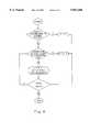
- FIG. 1shows a typical network configuration 1 such as described in U.S. Pat. No. 5,454,008 (Baumann et al.) also assigned to Echelon Corporation.
- the cellsare denoted by a plurality of nodes 2 which are interconnected by twisted pair lines 3.
- the linesform numerous branches each having a single node connected thereto and all of which receive power over the twisted pair lines from a central power supply 4.
- the power supply 4is connected to the network 1 through a source coupler 5.
- each nodeforms an effective line termination so that more nodes can be accommodated in the network simply by connecting additional branches where required and terminating each branch with a new node.
- Such a network configurationpermits relatively easy extension so as to accommodate additional nodes whilst reducing the cabling overhead as compared with known star topologies.
- the bus topology shown in FIG. 1requires complicated addressing in order to permit each cell or node to be individually addressed.
- a transmitting nodeties up the whole network thus preventing two or more nodes from transmitting data simultaneously.
- nodes or cells shown in above-mentioned U.S. Pat. No. 4,918,690 as well as in other prior art systemsgenerally employ a centralized management whereby each node operates in accordance with logic external to the nodes themselves.
- control networks of the kind describedderives from the superimposition of data on a power signal in a manner such as is described in U.S. Pat. No. 5,148,144 (Sutterlin et al.) also assigned to Echelon Corporation.
- Such topologiesare dictated by the topology of domestic and industrial wiring distribution systems which have, for the most part, employed radial or star topologies whereby each power outlet is connected in a radial fashion to a central distribution board.
- each cellis adapted for coupling to a respective power outlet, then it will necessarily form a non-distributed network having a star topology.
- addressingmust be effected by means of a unique ID burnt into the cell during manufacture or manually during installation. This renders the network inflexible because the controller must be programmed so as to know in advance the location in the network of each cell. Therefore, if cells are interchanged, added or removed then the controller must be re-programmed accordingly: there being no provision in such topologies to allocate addresses "on the fly" during processing in real time.
- each cellcan be controlled via control logic stored integrally therein instead of, or in addition to, an external control manager and which allows serial connection of cells so as thereby to reduce cabling.
- PSICsline-Powered, Serially connected Intelligent Cells
- At least one payload elementcoupled to one of the PSICs for operating in accordance with control logic embedded in or fed to said one of the PSICs.
- control datais superimposed on the power signal and is extracted within each cell from the power signal received from a preceding cell in the network and, likewise, is superimposed on the power signal fed to a succeeding cell in the network.
- powercan be fed discretely to all of the cells in the network in a bus-type of arrangement, only the data itself being fed serially in either or both directions from one cell to another.
- FIG. 1shows schematically a typical prior art distributed network
- FIG. 2shows schematically a distributed serial network according to the invention
- FIG. 3is a block diagram showing functionally the principal components in a PSIC for use with the network illustrated in FIG. 1;
- FIG. 4is a flow diagram showing the principal operating steps for effecting addressing of each individual PSIC in such a network.
- FIG. 2shows a distributed intelligent network depicted generally as 10 comprising a power source 11 for feeding power via a twisted wire pair 12 to a line-Powered, Serially connected Intelligent Cell (PSIC) 13 which is in turn serially connected to other PSICs 14, 15, 16 and 17 via respective twisted wire pairs 18, 19, 20 and 21 (constituting respective bi-directional communication channels).
- PSICLine-Powered, Serially connected Intelligent Cell
- the PSICs 13, 14, 15, 16 and 17will be referred to as first, second, third, fourth and fifth PSICs, respectively and, indeed, it is according to this order that the PSICs are individually addressed so that data which is serially transmitted in either direction along the bi-directional communication channels constituted by the twisted wire pairs will be correctly directed to or from the appropriate PSIC.
- a sensor 22is connected to an input of the first PSIC 13; a pair of sensors 23 and 24 are connected to respective inputs of the third PSIC 15 and a sensor 25 is also connected to one input of the fifth PSIC 17. Likewise, a pair of actuators 26 and 27 are connected to respective outputs of the second PSIC 14 and an actuator 28 is also connected to an output of the fifth PSIC 17.
- a Manager 29is coupled to an input of the third PSIC 15 and constitutes an external logic control and monitoring element for feeding predetermined logic to the network in order to direct the PSICs how to route control data to other PSICs in the network and how to control any actuators coupled thereto and for monitoring the status of PSICs, actuators and sensors in the network.
- the PSICs 13 to 17are not necessarily identical.
- the first PSIC 13has two outputs: one connected to an input of the second PSIC 14 and the other connected to an input of the fourth PSIC 16.
- all of the PSICsare indeed characterized by having a single power input only.
- there may be connected to the PSICoptionally a sensor or an actuator or, indeed, nothing at all as is the case with the fourth PSIC 16.
- That PSICWhen no payload element is connected to a PSIC, that PSIC functions as a repeater for amplifying the power/data signal on the communication channel in order to compensate for attenuation of the signal over long communication lines.
- Such repeaterswhich are commonly provided at intervals over long lengths of communication channels are known per se and are described, for example, in the above-referenced U.S. Pat. No. 5,454,008 to Baumann et al. the contents of which are incorporated herein by reference.
- an external logic control unit constituted by the Manager 29may, optionally, be connected to one of the PSICs in the network 10.
- the Manager 29may supplement discrete logic stored in each of the PSICs or, if desired, may obviate the need for any internal logic to be provided within the PSICs.
- the sensor 22may be a light dependent resistor and the actuator 28 might be an illumination lamp controlled by the PSIC 17 so as to control the brightness thereof as a function of the level of illumination falling on the sensor 22.
- the actuator 28would be responsive to a control signal representative of the required illumination level and this signal would be generated by the fifth PSIC 17 either in accordance with local logic contained therein, or in accordance with logic transmitted through the network 10 from the Manager 29 or, indeed, in accordance with a combination thereof.
- data representative of a sensor signal generated by the sensor 22is fed by the first PSIC 13 to the Manager 29 via the second and third PSICs 14 and 15, respectively; and is fed, via the fourth PSIC 16 to the fifth PSIC 17.
- both the Manager 29 and the fifth PSIC 17 having the actuator 28 connected theretomay respond to the illumination level on the sensor 22 so as to generate the correct control signal for controlling the actuator 28.
- the control signalis fed serially along the twisted pair lines 19 and 18 to the first PSIC 13 from which it is then fed serially along the twisted pair lines 20 and 21 to the fifth PSIC 17.
- status datais fed by each of the PSICs in the network to the Manager 29 so as to allow the Manager 29 to monitor the status of all sensors and actuators in the network 10.
- the actuator 28is responsive to a sensor signal which may itself be generated remote from the actuator 28.
- the actuatormay be responsive to a sensor connected to the same PSIC as the actuator. Indeed, multiple sensors and multiple actuators can be connected to the same PSIC providing, of course, that sufficient sensor and actuator interfaces are provided therein.
- All of the PSICs in the network 10 except the first PSIC 13 as well as the third and fifth PSICs 15 and 17, respectively,receive both power and data from a preceding PSIC and also feed power and data to a succeeding PSIC.
- the third and fifth PSICs 15 and 17, respectivelymay, of course, generally be provided with an interface to connect another PSIC thereto even though the interface is not actually used.
- the first PSIC 13is different from the other PSICs in that it receives power from the power source 11 but does not receive data therefrom. Likewise, of course, it does not feed data received from succeeding PSICs to the power source 11. For this reason, the first PSIC 13 is not completely representative of the general PSIC architecture which is better described with reference to the second PSIC 14.
- FIG. 3is a block diagram showing the functional components which may be provided in the PSIC 14 in the case where power and data are transmitted together.
- the manner in which power and data may be delivered in a data communications network over the same cable bundle to a plurality of communications nodes thereinis itself known and has long been used in telephony as described in the opening section of above-mentioned U.S. Pat. No. 5,148,144 to Sutterlin et al. the contents of which are incorporated herein by reference.
- the second PSIC 14includes a line interface 30 constituting a first port for coupling to the first PSIC 13 so as to receive therefrom a first incoming power and data signal.
- the incoming combined signalis fed to a power/data coupler/de-coupler 31 which de-couples the first incoming data signal from the incoming power signal.
- the separated first data signalis fed to a modem 32 whilst the d.c. or a.c. power signal itself is fed to a power handling unit 33 for producing therefrom a first outgoing power signal for supplying power to a power supply 34 coupled thereto and which has several output channels, as required, for powering the local circuitry in the PSIC 14.
- the first incoming data signal received by the modem 32is analog and is converted to digital form for feeding to a processing and control unit 35 which processes the first incoming data signal according to control logic stored therein or, alternatively or additionally, in accordance with external logic fed by the Manager 29 to the processing and control unit 35 via a communication port 36 coupled thereto.
- processing and control unit 35may be responsive to various sensor signals each fed thereto via a respective sensor interface 37 and, as explained above, the processing and control unit 35 may be coupled to a plurality of actuator interfaces 38 each for coupling a respective actuator to the processing and control unit 35.
- the processing and control unit 35processes the first incoming data signal and produces a first outgoing data signal which is converted to an analog signal by a modem 39 and fed to a second power/data coupler/de-coupler 40 (constituting a second data coupling/de-coupling means) which receives the a.c. or d.c. power signal from the power handling unit 33 to which it is also coupled and combines the first outgoing data signal with the first outgoing power signal so as to generate a first outgoing power and data signal which is fed to a line interface 41.
- the line interface 41constitutes a second port allowing the PSIC 14 to be connected to a corresponding successive PSIC. If desired, multiple PSICs can be coupled to the PSIC 14 via corresponding second ports each comprising a line interface 41 connected to a respective modem 39 and second power/data coupler/de-coupler 40.
- each sensor interface 37 and actuator interface 38constitutes a payload port for allowing a respective payload element to be connected to the processing and control unit 35.
- each of the sensor interfaces 37 and the actuator interfaces 38a corresponding payload power interface 42 which itself is coupled to the power handling unit 33 as well as being operatively coupled to the processing and control unit 35 for receiving a control signal therefrom and for sending a monitoring signal thereto.
- the line interface 30has been considered as the receiving interface to which the first incoming power and data signal is fed whilst the line interface 41 feeds the corresponding first outgoing power and data signal to successive PSICs connected thereto.
- the communication channels in the network 10are bi-directional and the PSIC 14 is thus equally well suited to receive a second incoming data signal from a successive PSIC.
- the power/data coupler/de-coupler 40de-couples the second incoming data signal from the first outgoing power signal and the modem 39 converts the analog second incoming data signal to a digital equivalent for feeding to the processing and control unit 35.
- the modem 32then reconverts the digital signal to an analog equivalent and the power/data coupler/de-coupler 31 superimposes the analog signal on the incoming power signal so as to feed the second outgoing data signal to the line interface 30.
- the first modem 32allows for simultaneous, full duplex, handling of a first incoming data signal and a second outgoing data signal whilst, at the same time, the second modem 39 allows for simultaneous, full duplex, handling of a first outgoing data signal and a second incoming data signal.
- the PSIC 14allows for four independent communications to be carried out simultaneously.
- the inventionis characterized by the serial connection of the PSICs so as to allow data to be fed from one PSIC to the next in either direction, it is not a requirement that the data be superimposed on the power signal.
- the powercan be fed to each of the PSICs in the network via a common power bus or can be fed radially to each PSIC using a known star topology.
- the power/data coupler/decouplers 31 and 40can then be dispensed with since the power and data signals are handled discretely. Indeed, even in the case where data and power are fed over the same twisted pair line, it will be noted that the first PSIC 13 receives only power from the power source 11 whilst data may be fed thereto only via the second PSIC 14.
- the power/data coupler/decoupler 31may be dispensed with since the power signal is fed directly to the power handling unit 33.
- the power/data coupler/decoupler 40 in the last PSICi.e. the fifth PSIC 17 in the particular example shown in FIG. 2 may be dispensed with since no succeeding PSIC is connected thereto.
- the simplified fifth PSIC 17it would then be necessary to replace the simplified fifth PSIC 17 with one having a line interface 41 connected to a power/data coupler/decoupler 40.
- each data packetcontains a header defining the source and destination addresses according to a predetermined protocol, as is known in the art.
- FIG. 4is a flow diagram showing the principal steps associated with discretely and uniquely addressing each of the PSICs shown in the network 10 according to the topology of the network.
- the network topologydictates the number of PSICs in the main branch constituted by the first, second and third PSICs 13, 14 and 15 respectively.
- Subsequent PSICsoperate according as to whether they are connected to the first output of the preceding PSIC or, in the simple case, where only two branches are provided, to the second output thereof. In this case, a PSIC which is connected to the first output of the preceding PSIC assigns itself an internal address I N equal to the index of the preceding PSIC+1, i.e. I N-1 +1.
- the index I N of the current PSICis set to one plus the number of PSICs in the main branch.
- the index of the fourth PSICwill be set to (1+3) i.e. 4.
- FIG. 4is adapted to the particular network construction shown in FIG. 2 but is amenable to simple adaptation in the case where additional branches are provided. This process can be performed independently and automatically, e.g. on powering up the system.
- Alternative methods of providing the addressing logicare to provide an encoder in each PSIC which may be manually set to a discrete address known also to the Manager 29, if provided.
- the encodercan be in the form of a DIP switch as is commonly used in network cards or can be in the form of a unique address code stored in ROM. If desired, a combination can be employed whereby some of the address codes are stored within the PSIC whilst other addresses are allocated "on the fly" based on the network topology according to the logic shown in FIG. 4.
- Such an arrangementis particularly suited where multiple branches are employed so that, for example, the first PSIC in each branch can be hardware programmed with specific addresses suitably offset to allow addition of further PSICs to the respective branches without conflicting with the respective addresses of the first PSICs in subsequent branches.
- the first PSIC 13 in the first branchcan be given an address of 1 in the normal manner whilst the first PSIC 16 in the second branch can be given an address equal to 100.
- the Manager 29In the case where an external control unit is provided in the form of the Manager 29, it is obviously necessary that the Manager 29 be pre-programmed so that it knows what action to take in respect of each of the PSICs and, to this end, is aware of the first PSIC in each branch. However, in those cases where the Manager 29 is dispensed with, it is only necessary that each PSIC knows its own address and that the data sent to each PSIC in order to operate one or more actuators connected thereto is suitably encoded with the correct PSIC address.
- the networkmay be provided with only a single payload element.
- Thismight be an actuator for responding to logic fed to a PSIC to which the actuator is connected or within which the logic is stored.
- the payload elementmay be a sensor for relaying a respective control signal to different PSICs in the network dependent on the sensor signal generated thereby.
- Such an arrangementmight be of use, for example, for coupling the network to a remote system having actuators responsive to the control signals generated by the network.
- the sensorsmay be any device which produces more than one fixed output signal according to a status of the sensor.
- the sensorcould optionally be a manual selector switch whose output is determined according to which switch position is selected.
- control signal produced by the processing and control unitmay be wholly or partially constituted by data which is ultimately input to a database connected either directly or indirectly to the network.
- the networkcan be used to feed data in only one direction, if desired.
- the term "preceding" as applied to PSICindicates a PSIC which is coupled to an adjacent PSIC and feeds power thereto.
- the term “succeeding” as applied to PSICindicates a PSIC which is coupled to an adjacent PSIC for receiving power therefrom.
- the inventionthus provides an intelligent, distributed network wherein a plurality of intelligent cells are serially connected via bi-directional communication channels permitting data (and optionally power) to be fed serially along the network from one PSIC to the other, in either direction.
Landscapes
- Engineering & Computer Science (AREA)
- Automation & Control Theory (AREA)
- Computer Networks & Wireless Communication (AREA)
- Signal Processing (AREA)
- Human Computer Interaction (AREA)
- Multimedia (AREA)
- Small-Scale Networks (AREA)
Abstract
Description
Claims (24)
Priority Applications (4)
| Application Number | Priority Date | Filing Date | Title |
|---|---|---|---|
| IL11945496AIL119454A (en) | 1996-10-21 | 1996-10-21 | Distributed serial control system |
| US08/734,921US5841360A (en) | 1996-10-21 | 1996-10-22 | Distributed serial control system |
| AU30463/97AAU3046397A (en) | 1996-10-21 | 1997-06-16 | Distributed serial control system |
| PCT/IL1997/000195WO1998018236A1 (en) | 1996-10-21 | 1997-06-16 | Distributed serial control system |
Applications Claiming Priority (3)
| Application Number | Priority Date | Filing Date | Title |
|---|---|---|---|
| IL11945496AIL119454A (en) | 1996-10-21 | 1996-10-21 | Distributed serial control system |
| US08/734,921US5841360A (en) | 1996-10-21 | 1996-10-22 | Distributed serial control system |
| PCT/IL1997/000195WO1998018236A1 (en) | 1996-10-21 | 1997-06-16 | Distributed serial control system |
Publications (1)
| Publication Number | Publication Date |
|---|---|
| US5841360Atrue US5841360A (en) | 1998-11-24 |
Family
ID=26323315
Family Applications (1)
| Application Number | Title | Priority Date | Filing Date |
|---|---|---|---|
| US08/734,921Expired - LifetimeUS5841360A (en) | 1996-10-21 | 1996-10-22 | Distributed serial control system |
Country Status (4)
| Country | Link |
|---|---|
| US (1) | US5841360A (en) |
| AU (1) | AU3046397A (en) |
| IL (1) | IL119454A (en) |
| WO (1) | WO1998018236A1 (en) |
Cited By (72)
| Publication number | Priority date | Publication date | Assignee | Title |
|---|---|---|---|---|
| US6212457B1 (en) | 1999-08-05 | 2001-04-03 | Trw Inc. | Mixed parallel and daisy chain bus architecture in a vehicle safety system |
| WO2001005092A3 (en)* | 1999-07-07 | 2001-05-17 | Serconet Ltd | Local area network for distributing data communication, sensing and control signals |
| WO2001050684A1 (en)* | 1999-12-30 | 2001-07-12 | C-Smart Llc | Method and apparatus for providing distributed control of a home automation system |
| EP1189036A1 (en)* | 2000-09-19 | 2002-03-20 | Endress + Hauser GmbH + Co. | Method for providing measuring values and method for calculation of the costs for providing these values |
| US6449348B1 (en)* | 1997-05-29 | 2002-09-10 | 3Com Corporation | Power transfer apparatus for use by network devices including telephone equipment |
| US6473660B1 (en) | 1999-12-03 | 2002-10-29 | The Foxboro Company | Process control system and method with automatic fault avoidance |
| US6501995B1 (en) | 1999-06-30 | 2002-12-31 | The Foxboro Company | Process control system and method with improved distribution, installation and validation of components |
| US6510352B1 (en) | 1999-07-29 | 2003-01-21 | The Foxboro Company | Methods and apparatus for object-based process control |
| US20030040812A1 (en)* | 1999-12-30 | 2003-02-27 | C-Smart Corporation | Method and apparatus for providing distributed control of a home automation and control system |
| US6549616B1 (en) | 2000-03-20 | 2003-04-15 | Serconet Ltd. | Telephone outlet for implementing a local area network over telephone lines and a local area network using such outlets |
| US6640308B1 (en) | 1999-04-16 | 2003-10-28 | Invensys Systems, Inc. | System and method of powering and communicating field ethernet device for an instrumentation and control using a single pair of powered ethernet wire |
| US20040015570A1 (en)* | 2002-07-18 | 2004-01-22 | Wolfgang Daum | Reconfigurable appliance control system |
| US6686831B2 (en) | 2001-01-23 | 2004-02-03 | Invensys Systems, Inc. | Variable power control for process control instruments |
| US6690677B1 (en) | 1999-07-20 | 2004-02-10 | Serconet Ltd. | Network for telephony and data communication |
| US6754885B1 (en) | 1999-05-17 | 2004-06-22 | Invensys Systems, Inc. | Methods and apparatus for controlling object appearance in a process control configuration system |
| US6788980B1 (en) | 1999-06-11 | 2004-09-07 | Invensys Systems, Inc. | Methods and apparatus for control using control devices that provide a virtual machine environment and that communicate via an IP network |
| US6823223B2 (en) | 1999-12-30 | 2004-11-23 | Microsoft Corporation | Method and apparatus for providing distributed scene programming of a home automation and control system |
| US6842459B1 (en) | 2000-04-19 | 2005-01-11 | Serconet Ltd. | Network combining wired and non-wired segments |
| US6990379B2 (en) | 1999-12-30 | 2006-01-24 | Microsoft Corporation | Method and apparatus for providing a dynamic resource role model for subscriber-requester based protocols in a home automation and control system |
| US20060028997A1 (en)* | 2004-08-09 | 2006-02-09 | Mcfarland Norman R | Wireless building control architecture |
| US7006523B2 (en) | 1998-07-28 | 2006-02-28 | Serconet Ltd. | Local area network of serial intelligent cells |
| US20060165097A1 (en)* | 2004-11-18 | 2006-07-27 | Caveney Jack E | Ethernet-to-analog controller |
| US7089530B1 (en) | 1999-05-17 | 2006-08-08 | Invensys Systems, Inc. | Process control configuration system with connection validation and configuration |
| US20060176044A1 (en)* | 2005-01-23 | 2006-08-10 | Serconet Ltd. | Device, method and system for estimating the termination to a wired transmission-line based on determination of characteristic impedance |
| US7096465B1 (en) | 1999-05-17 | 2006-08-22 | Invensys Systems, Inc. | Process control configuration system with parameterized objects |
| US7106721B1 (en) | 2000-04-18 | 2006-09-12 | Serconet, Ltd. | Telephone communication system over a single telephone line |
| US7139648B1 (en)* | 1999-11-03 | 2006-11-21 | Behr Gmbh & Co. | Apparatus for actuating a control element for a heating or air-conditioning system in a motor vehicle |
| US20070041339A1 (en)* | 2003-09-07 | 2007-02-22 | Serconet Ltd. | Modular outlet |
| US7272815B1 (en) | 1999-05-17 | 2007-09-18 | Invensys Systems, Inc. | Methods and apparatus for control configuration with versioning, security, composite blocks, edit selection, object swapping, formulaic values and other aspects |
| US7317793B2 (en) | 2003-01-30 | 2008-01-08 | Serconet Ltd | Method and system for providing DC power on local telephone lines |
| US7330695B2 (en) | 2003-12-12 | 2008-02-12 | Rosemount, Inc. | Bus powered wireless transmitter |
| EP1905192A2 (en)* | 2005-07-19 | 2008-04-02 | Rosemount, Inc. | Interface module with power over ethernet function |
| US20080129331A1 (en)* | 2000-09-17 | 2008-06-05 | Serconet, Ltd. | System for transmission line termination by signal cancellation |
| US7436842B2 (en) | 2001-10-11 | 2008-10-14 | Serconet Ltd. | Outlet with analog signal adapter, a method for use thereof and a network using said outlet |
| US7447144B2 (en) | 2000-09-21 | 2008-11-04 | Serconet, Ltd. | Telephone communication system and method over local area network wiring |
| US20080273475A1 (en)* | 2007-05-03 | 2008-11-06 | Microsoft Corporation | Reconfigurable computer bus |
| US7502656B2 (en) | 1996-08-20 | 2009-03-10 | Invensys Systems, Inc. | Methods and apparatus for remote process control |
| US7522615B2 (en) | 2002-11-13 | 2009-04-21 | Serconet, Ltd. | Addressable outlet, and a network using same |
| US7542554B2 (en) | 2001-07-05 | 2009-06-02 | Serconet, Ltd | Telephone outlet with packet telephony adapter, and a network using same |
| US20090153487A1 (en)* | 2007-12-12 | 2009-06-18 | Gunther Adam M | Data input device having a plurality of key stick devices for fast typing and method thereof |
| US7579548B2 (en) | 2001-09-25 | 2009-08-25 | Mosaid Technologies Incorporated | Adapter for mounting a faceplate of a first style to an electrical outlet cavity of a second style |
| US7587001B2 (en) | 2006-01-11 | 2009-09-08 | Serconet Ltd. | Apparatus and method for frequency shifting of a wireless signal and systems using frequency shifting |
| US7656904B2 (en) | 2003-03-13 | 2010-02-02 | Mosaid Technologies Incorporated | Telephone system having multiple distinct sources and accessories therefor |
| US7756268B2 (en) | 2004-02-16 | 2010-07-13 | Mosaid Technologies Incorporated | Outlet add-on module |
| US7761923B2 (en) | 2004-03-01 | 2010-07-20 | Invensys Systems, Inc. | Process control methods and apparatus for intrusion detection, protection and network hardening |
| US20100186234A1 (en)* | 2009-01-28 | 2010-07-29 | Yehuda Binder | Electric shaver with imaging capability |
| US7778717B2 (en) | 2002-04-15 | 2010-08-17 | Invensys Systems, Inc. | Component object model communication method for a control system |
| US7860857B2 (en) | 2006-03-30 | 2010-12-28 | Invensys Systems, Inc. | Digital data processing apparatus and methods for improving plant performance |
| US7873058B2 (en) | 2004-11-08 | 2011-01-18 | Mosaid Technologies Incorporated | Outlet with analog signal adapter, a method for use thereof and a network using said outlet |
| WO2011006558A1 (en)* | 2009-07-17 | 2011-01-20 | Festo Ag & Co. Kg | Device for transmitting data between a serial data bus and working modules, such as actuator modules and/or i/o modules |
| WO2011007349A1 (en) | 2009-07-15 | 2011-01-20 | Yehuda Binder | Sequentially operated modules |
| US7890927B2 (en) | 1999-05-17 | 2011-02-15 | Invensys Systems, Inc. | Apparatus and method for configuring and editing a control system with live data |
| WO2011151773A1 (en)* | 2010-06-04 | 2011-12-08 | Koninklijke Philips Electronics N.V. | Cascaded power-over-ethernet system |
| US8127060B2 (en) | 2009-05-29 | 2012-02-28 | Invensys Systems, Inc | Methods and apparatus for control configuration with control objects that are fieldbus protocol-aware |
| US8155012B2 (en) | 1998-04-10 | 2012-04-10 | Chrimar Systems, Inc. | System and method for adapting a piece of terminal equipment |
| US8175649B2 (en) | 2008-06-20 | 2012-05-08 | Corning Mobileaccess Ltd | Method and system for real time control of an active antenna over a distributed antenna system |
| ITPD20110006A1 (en)* | 2011-01-13 | 2012-07-14 | Vimar Spa | DOMOTIC SYSTEM |
| US8325759B2 (en) | 2004-05-06 | 2012-12-04 | Corning Mobileaccess Ltd | System and method for carrying a wireless based signal over wiring |
| US8463964B2 (en) | 2009-05-29 | 2013-06-11 | Invensys Systems, Inc. | Methods and apparatus for control configuration with enhanced change-tracking |
| US8594814B2 (en) | 2008-06-20 | 2013-11-26 | Invensys Systems, Inc. | Systems and methods for immersive interaction with actual and/or simulated facilities for process, environmental and industrial control |
| US8594133B2 (en) | 2007-10-22 | 2013-11-26 | Corning Mobileaccess Ltd. | Communication system using low bandwidth wires |
| US8602833B2 (en) | 2009-08-06 | 2013-12-10 | May Patents Ltd. | Puzzle with conductive path |
| US8614673B2 (en) | 2009-05-21 | 2013-12-24 | May Patents Ltd. | System and method for control based on face or hand gesture detection |
| US8897215B2 (en) | 2009-02-08 | 2014-11-25 | Corning Optical Communications Wireless Ltd | Communication system using cables carrying ethernet signals |
| US9184960B1 (en) | 2014-09-25 | 2015-11-10 | Corning Optical Communications Wireless Ltd | Frequency shifting a communications signal(s) in a multi-frequency distributed antenna system (DAS) to avoid or reduce frequency interference |
| US9338823B2 (en) | 2012-03-23 | 2016-05-10 | Corning Optical Communications Wireless Ltd | Radio-frequency integrated circuit (RFIC) chip(s) for providing distributed antenna system functionalities, and related components, systems, and methods |
| US9419378B2 (en) | 2011-08-26 | 2016-08-16 | Littlebits Electronics Inc. | Modular electronic building systems with magnetic interconnections and methods of using the same |
| US9597607B2 (en) | 2011-08-26 | 2017-03-21 | Littlebits Electronics Inc. | Modular electronic building systems with magnetic interconnections and methods of using the same |
| CN110839091A (en)* | 2019-11-18 | 2020-02-25 | 派诺西智能科技(苏州)有限公司 | Bus type communication control system and online addressing method |
| US10986164B2 (en) | 2004-01-13 | 2021-04-20 | May Patents Ltd. | Information device |
| US11330714B2 (en) | 2011-08-26 | 2022-05-10 | Sphero, Inc. | Modular electronic building systems with magnetic interconnections and methods of using the same |
| US11616844B2 (en) | 2019-03-14 | 2023-03-28 | Sphero, Inc. | Modular electronic and digital building systems and methods of using the same |
Families Citing this family (2)
| Publication number | Priority date | Publication date | Assignee | Title |
|---|---|---|---|---|
| DE19922467B4 (en)* | 1999-05-18 | 2006-12-07 | Jochen Bihl | Method and device for separation of voltage source and data decoupling in AS-Interface |
| JP2001267975A (en)* | 2000-03-21 | 2001-09-28 | Fukushima Industries Corp | Connection structure of communication line of refrigeration and cooling system |
Citations (5)
| Publication number | Priority date | Publication date | Assignee | Title |
|---|---|---|---|---|
| EP0468194A2 (en)* | 1990-07-26 | 1992-01-29 | Hewlett-Packard Company | Method and system for daisy chained communication |
| US5095417A (en)* | 1988-05-17 | 1992-03-10 | Kabushiki Kaisha Komatsu Seisakusho | Apparatus for carrying out serial control |
| US5454008A (en)* | 1993-04-20 | 1995-09-26 | Echelon Corporation | Method and apparatus for interfacing between a twisted pair and an intelligent cell |
| US5475687A (en)* | 1987-11-10 | 1995-12-12 | Echelon Corporation | Network and intelligent cell for providing sensing, bidirectional communications and control |
| US5535336A (en)* | 1990-09-19 | 1996-07-09 | Intel Corporation | Apparatus and method for enabling a network interface to dynamically assign an address to a connected computer and to establish a virtual circuit with another network interface |
Family Cites Families (1)
| Publication number | Priority date | Publication date | Assignee | Title |
|---|---|---|---|---|
| DE3818601A1 (en)* | 1988-06-01 | 1989-12-14 | Merten Gmbh & Co Kg Geb | DIGITAL SIGNAL TRANSFER SYSTEM FOR HOUSE CONTROL TECHNOLOGY |
- 1996
- 1996-10-21ILIL11945496Apatent/IL119454A/ennot_activeIP Right Cessation
- 1996-10-22USUS08/734,921patent/US5841360A/ennot_activeExpired - Lifetime
- 1997
- 1997-06-16AUAU30463/97Apatent/AU3046397A/ennot_activeAbandoned
- 1997-06-16WOPCT/IL1997/000195patent/WO1998018236A1/enactiveIP Right Grant
Patent Citations (5)
| Publication number | Priority date | Publication date | Assignee | Title |
|---|---|---|---|---|
| US5475687A (en)* | 1987-11-10 | 1995-12-12 | Echelon Corporation | Network and intelligent cell for providing sensing, bidirectional communications and control |
| US5095417A (en)* | 1988-05-17 | 1992-03-10 | Kabushiki Kaisha Komatsu Seisakusho | Apparatus for carrying out serial control |
| EP0468194A2 (en)* | 1990-07-26 | 1992-01-29 | Hewlett-Packard Company | Method and system for daisy chained communication |
| US5535336A (en)* | 1990-09-19 | 1996-07-09 | Intel Corporation | Apparatus and method for enabling a network interface to dynamically assign an address to a connected computer and to establish a virtual circuit with another network interface |
| US5454008A (en)* | 1993-04-20 | 1995-09-26 | Echelon Corporation | Method and apparatus for interfacing between a twisted pair and an intelligent cell |
Cited By (320)
| Publication number | Priority date | Publication date | Assignee | Title |
|---|---|---|---|---|
| US7502656B2 (en) | 1996-08-20 | 2009-03-10 | Invensys Systems, Inc. | Methods and apparatus for remote process control |
| US7979488B2 (en) | 1996-08-20 | 2011-07-12 | Invensys Systems, Inc. | Control system methods using value-based transfers |
| US8023500B2 (en) | 1996-08-20 | 2011-09-20 | Invensys Systems, Inc. | Methods for process control with change updates |
| US7899070B2 (en) | 1996-08-20 | 2011-03-01 | Invensys Systems, Inc. | Control system apparatus with change updates |
| US7882197B2 (en) | 1996-08-20 | 2011-02-01 | Invensys Systems, Inc. | Control system methods that transfer control apparatus information over IP networks in web page-less transfers |
| US8081584B2 (en) | 1996-08-20 | 2011-12-20 | Invensys Systems, Inc. | Control system apparatus and systems using value-based transfers |
| US7739361B2 (en) | 1996-08-20 | 2010-06-15 | Thibault Richard L | Methods for remote process control with networked digital data processors and a virtual machine environment |
| US7720944B2 (en) | 1996-08-20 | 2010-05-18 | Invensys Systems, Inc. | Process control system with networked digital data processors and a virtual machine environment |
| US6658098B2 (en)* | 1997-05-29 | 2003-12-02 | 3Com Corporation | Power transfer apparatus for use by network devices including telephone equipment |
| US6449348B1 (en)* | 1997-05-29 | 2002-09-10 | 3Com Corporation | Power transfer apparatus for use by network devices including telephone equipment |
| US8902760B2 (en) | 1998-04-10 | 2014-12-02 | Chrimar Systems, Inc. | Network system and optional tethers |
| US8155012B2 (en) | 1998-04-10 | 2012-04-10 | Chrimar Systems, Inc. | System and method for adapting a piece of terminal equipment |
| US9812825B2 (en) | 1998-04-10 | 2017-11-07 | Chrimar Systems, Inc. | Ethernet device |
| US9049019B2 (en) | 1998-04-10 | 2015-06-02 | Chrimar Systems, Inc. | Network equipment and optional tether |
| US9019838B2 (en) | 1998-04-10 | 2015-04-28 | Chrimar Systems, Inc. | Central piece of network equipment |
| US8942107B2 (en) | 1998-04-10 | 2015-01-27 | Chrimar Systems, Inc. | Piece of ethernet terminal equipment |
| US8325636B2 (en) | 1998-07-28 | 2012-12-04 | Mosaid Technologies Incorporated | Local area network of serial intelligent cells |
| US7016368B2 (en) | 1998-07-28 | 2006-03-21 | Serconet, Ltd. | Local area network of serial intelligent cells |
| US7292600B2 (en) | 1998-07-28 | 2007-11-06 | Serconet Ltd. | Local area network of serial intellegent cells |
| US8270430B2 (en) | 1998-07-28 | 2012-09-18 | Mosaid Technologies Incorporated | Local area network of serial intelligent cells |
| US7653015B2 (en) | 1998-07-28 | 2010-01-26 | Mosaid Technologies Incorporated | Local area network of serial intelligent cells |
| US7221679B2 (en) | 1998-07-28 | 2007-05-22 | Serconet Ltd. | Local area network of serial intelligent cells |
| US7830858B2 (en) | 1998-07-28 | 2010-11-09 | Mosaid Technologies Incorporated | Local area network of serial intelligent cells |
| US7424031B2 (en) | 1998-07-28 | 2008-09-09 | Serconet, Ltd. | Local area network of serial intelligent cells |
| US7187695B2 (en) | 1998-07-28 | 2007-03-06 | Serconet Ltd. | Local area network of serial intelligent cells |
| US7852874B2 (en) | 1998-07-28 | 2010-12-14 | Mosaid Technologies Incorporated | Local area network of serial intelligent cells |
| US8908673B2 (en) | 1998-07-28 | 2014-12-09 | Conversant Intellectual Property Management Incorporated | Local area network of serial intelligent cells |
| US8885659B2 (en) | 1998-07-28 | 2014-11-11 | Conversant Intellectual Property Management Incorporated | Local area network of serial intelligent cells |
| US8885660B2 (en) | 1998-07-28 | 2014-11-11 | Conversant Intellectual Property Management Incorporated | Local area network of serial intelligent cells |
| US7095756B2 (en) | 1998-07-28 | 2006-08-22 | Serconet, Ltd. | Local area network of serial intelligent cells |
| US7965735B2 (en) | 1998-07-28 | 2011-06-21 | Mosaid Technologies Incorporated | Local area network of serial intelligent cells |
| US7969917B2 (en) | 1998-07-28 | 2011-06-28 | Mosaid Technologies Incorporated | Local area network of serial intelligent cells |
| US7006523B2 (en) | 1998-07-28 | 2006-02-28 | Serconet Ltd. | Local area network of serial intelligent cells |
| US7986708B2 (en) | 1998-07-28 | 2011-07-26 | Mosaid Technologies Incorporated | Local area network of serial intelligent cells |
| US7035280B2 (en) | 1998-07-28 | 2006-04-25 | Serconet Ltd. | Local area network of serial intelligent cells |
| US8867523B2 (en) | 1998-07-28 | 2014-10-21 | Conversant Intellectual Property Management Incorporated | Local area network of serial intelligent cells |
| US7978726B2 (en) | 1998-07-28 | 2011-07-12 | Mosaid Technologies Incorporated | Local area network of serial intelligent cells |
| US6640308B1 (en) | 1999-04-16 | 2003-10-28 | Invensys Systems, Inc. | System and method of powering and communicating field ethernet device for an instrumentation and control using a single pair of powered ethernet wire |
| US8368640B2 (en) | 1999-05-17 | 2013-02-05 | Invensys Systems, Inc. | Process control configuration system with connection validation and configuration |
| US7272815B1 (en) | 1999-05-17 | 2007-09-18 | Invensys Systems, Inc. | Methods and apparatus for control configuration with versioning, security, composite blocks, edit selection, object swapping, formulaic values and other aspects |
| US7984420B2 (en) | 1999-05-17 | 2011-07-19 | Invensys Systems, Inc. | Control systems and methods with composite blocks |
| US6754885B1 (en) | 1999-05-17 | 2004-06-22 | Invensys Systems, Inc. | Methods and apparatus for controlling object appearance in a process control configuration system |
| US7089530B1 (en) | 1999-05-17 | 2006-08-08 | Invensys Systems, Inc. | Process control configuration system with connection validation and configuration |
| US8229579B2 (en) | 1999-05-17 | 2012-07-24 | Invensys Systems, Inc. | Control systems and methods with versioning |
| US7096465B1 (en) | 1999-05-17 | 2006-08-22 | Invensys Systems, Inc. | Process control configuration system with parameterized objects |
| US8028272B2 (en) | 1999-05-17 | 2011-09-27 | Invensys Systems, Inc. | Control system configurator and methods with edit selection |
| US8028275B2 (en) | 1999-05-17 | 2011-09-27 | Invensys Systems, Inc. | Control systems and methods with smart blocks |
| US7890927B2 (en) | 1999-05-17 | 2011-02-15 | Invensys Systems, Inc. | Apparatus and method for configuring and editing a control system with live data |
| US8060222B2 (en) | 1999-05-17 | 2011-11-15 | Invensys Systems, Inc. | Control system configurator and methods with object characteristic swapping |
| US8225271B2 (en) | 1999-05-17 | 2012-07-17 | Invensys Systems, Inc. | Apparatus for control systems with objects that are associated with live data |
| US8090452B2 (en) | 1999-06-11 | 2012-01-03 | Invensys Systems, Inc. | Methods and apparatus for control using control devices that provide a virtual machine environment and that communicate via an IP network |
| US6788980B1 (en) | 1999-06-11 | 2004-09-07 | Invensys Systems, Inc. | Methods and apparatus for control using control devices that provide a virtual machine environment and that communicate via an IP network |
| US7020532B2 (en) | 1999-06-11 | 2006-03-28 | Invensys Systems, Inc. | Methods and apparatus for control using control devices that provide a virtual machine environment and that communicate via an IP network |
| US6501995B1 (en) | 1999-06-30 | 2002-12-31 | The Foxboro Company | Process control system and method with improved distribution, installation and validation of components |
| US6956826B1 (en) | 1999-07-07 | 2005-10-18 | Serconet Ltd. | Local area network for distributing data communication, sensing and control signals |
| EP1783960A2 (en) | 1999-07-07 | 2007-05-09 | Serconet Ltd. | Local area network for distributing data communication, sensing and control signals |
| EP2264948A1 (en) | 1999-07-07 | 2010-12-22 | Mosaid Technologies Incorporated | Local area network for distributing data communication, sensing and control signals |
| US7200152B2 (en) | 1999-07-07 | 2007-04-03 | Serconet, Ltd. | Local area network for distributing data communication, sensing and control signals |
| US7835386B2 (en) | 1999-07-07 | 2010-11-16 | Mosaid Technologies Incorporated | Local area network for distributing data communication, sensing and control signals |
| US20050259602A1 (en)* | 1999-07-07 | 2005-11-24 | Serconet, Ltd. | Local area network for distributing data communication, sensing and control signals |
| US20070274336A1 (en)* | 1999-07-07 | 2007-11-29 | Serconet, Ltd. | Local area network for distributing data communication, sensing and control signals |
| US20140050228A1 (en)* | 1999-07-07 | 2014-02-20 | Mosaid Technologies Incorporated | Local area network for distributing data communication, sensing and control signals |
| EP1783960A3 (en)* | 1999-07-07 | 2010-05-12 | MOSAID Technologies Incorporated | Local area network for distributing data communication, sensing and control signals |
| US8121132B2 (en) | 1999-07-07 | 2012-02-21 | Mosaid Technologies Incorporated | Local area network for distributing data communication, sensing and control signals |
| WO2001005092A3 (en)* | 1999-07-07 | 2001-05-17 | Serconet Ltd | Local area network for distributing data communication, sensing and control signals |
| US7492875B2 (en) | 1999-07-20 | 2009-02-17 | Serconet, Ltd. | Network for telephony and data communication |
| US7522713B2 (en) | 1999-07-20 | 2009-04-21 | Serconet, Ltd. | Network for telephony and data communication |
| US6690677B1 (en) | 1999-07-20 | 2004-02-10 | Serconet Ltd. | Network for telephony and data communication |
| US20040165616A1 (en)* | 1999-07-20 | 2004-08-26 | Serconet Ltd. | Networks for telephony and data communication |
| EP1973322A2 (en) | 1999-07-20 | 2008-09-24 | Serconet Ltd. | Device for telephony |
| US8929523B2 (en) | 1999-07-20 | 2015-01-06 | Conversant Intellectual Property Management Inc. | Network for telephony and data communication |
| EP2276229A1 (en) | 1999-07-20 | 2011-01-19 | Mosaid Technologies Incorporated | Device for telephony and data communication |
| JP2013229942A (en)* | 1999-07-20 | 2013-11-07 | Mosaid Technologies Inc | Network for telephony and data communication |
| JP2009213163A (en)* | 1999-07-20 | 2009-09-17 | Serconet Ltd | Telephone communication and data communication network |
| US20050105477A1 (en)* | 1999-07-20 | 2005-05-19 | Serconet, Ltd. | Network for telephony and data communication |
| US20050226226A1 (en)* | 1999-07-20 | 2005-10-13 | Serconet, Ltd. | Network for telephony and data communication |
| US6970538B2 (en) | 1999-07-20 | 2005-11-29 | Serconet Ltd. | Networks for telephony and data communication |
| US8351582B2 (en) | 1999-07-20 | 2013-01-08 | Mosaid Technologies Incorporated | Network for telephony and data communication |
| US7483524B2 (en) | 1999-07-20 | 2009-01-27 | Serconet, Ltd | Network for telephony and data communication |
| US6510352B1 (en) | 1999-07-29 | 2003-01-21 | The Foxboro Company | Methods and apparatus for object-based process control |
| US6212457B1 (en) | 1999-08-05 | 2001-04-03 | Trw Inc. | Mixed parallel and daisy chain bus architecture in a vehicle safety system |
| US7139648B1 (en)* | 1999-11-03 | 2006-11-21 | Behr Gmbh & Co. | Apparatus for actuating a control element for a heating or air-conditioning system in a motor vehicle |
| US6473660B1 (en) | 1999-12-03 | 2002-10-29 | The Foxboro Company | Process control system and method with automatic fault avoidance |
| US6970751B2 (en) | 1999-12-30 | 2005-11-29 | Microsoft Corporation | Method and apparatus for providing distributed scene programming of a home automation and control system |
| US20050055108A1 (en)* | 1999-12-30 | 2005-03-10 | C-Smart Corporation | Method and apparatus for providing distributed control of a home automation and control system |
| US20030040812A1 (en)* | 1999-12-30 | 2003-02-27 | C-Smart Corporation | Method and apparatus for providing distributed control of a home automation and control system |
| US7099723B2 (en) | 1999-12-30 | 2006-08-29 | Microsoft Corporation | Providing distributed scene programming of a home automation and control system |
| WO2001050684A1 (en)* | 1999-12-30 | 2001-07-12 | C-Smart Llc | Method and apparatus for providing distributed control of a home automation system |
| US6990379B2 (en) | 1999-12-30 | 2006-01-24 | Microsoft Corporation | Method and apparatus for providing a dynamic resource role model for subscriber-requester based protocols in a home automation and control system |
| US20030040813A1 (en)* | 1999-12-30 | 2003-02-27 | C-Smart Corporation | Method and apparatus for providing distributed control of a home automation system |
| US6834208B2 (en) | 1999-12-30 | 2004-12-21 | Microsoft Corporation | Method and apparatus for providing distributed control of a home automation and control system |
| US20050085930A1 (en)* | 1999-12-30 | 2005-04-21 | C-Smart Corporation | Method and apparatus for providing distributed scene programming of a home automation and control system |
| US6865428B2 (en) | 1999-12-30 | 2005-03-08 | Microsoft Corporation | Method and apparatus for providing distributed control of a home automation system |
| US20060020353A1 (en)* | 1999-12-30 | 2006-01-26 | Microsoft Corporation | Providing distributed scene programming of a home automation and control system |
| US6823223B2 (en) | 1999-12-30 | 2004-11-23 | Microsoft Corporation | Method and apparatus for providing distributed scene programming of a home automation and control system |
| US7123701B2 (en) | 2000-03-20 | 2006-10-17 | Serconet, Ltd. | Telephone outlet for implementing a local area network over telephone lines and a local area network using such outlets |
| US6549616B1 (en) | 2000-03-20 | 2003-04-15 | Serconet Ltd. | Telephone outlet for implementing a local area network over telephone lines and a local area network using such outlets |
| US20040196835A1 (en)* | 2000-03-20 | 2004-10-07 | Serconet Ltd. | Telephone outlet for implementing a local area network over telephone lines and a local area network using such outlets |
| US8855277B2 (en) | 2000-03-20 | 2014-10-07 | Conversant Intellectual Property Managment Incorporated | Telephone outlet for implementing a local area network over telephone lines and a local area network using such outlets |
| US7522714B2 (en) | 2000-03-20 | 2009-04-21 | Serconet Ltd. | Telephone outlet for implementing a local area network over telephone lines and a local area network using such outlets |
| US8363797B2 (en) | 2000-03-20 | 2013-01-29 | Mosaid Technologies Incorporated | Telephone outlet for implementing a local area network over telephone lines and a local area network using such outlets |
| US7593394B2 (en) | 2000-04-18 | 2009-09-22 | Mosaid Technologies Incorporated | Telephone communication system over a single telephone line |
| CN1826017B (en)* | 2000-04-18 | 2012-09-05 | 莫塞德技术公司 | Telephone communication system over a single telephone line |
| US7106721B1 (en) | 2000-04-18 | 2006-09-12 | Serconet, Ltd. | Telephone communication system over a single telephone line |
| US7397791B2 (en) | 2000-04-18 | 2008-07-08 | Serconet, Ltd. | Telephone communication system over a single telephone line |
| EP2117256A1 (en) | 2000-04-18 | 2009-11-11 | Mosaid Technologies Incorporated | Telephone communication network |
| US8223800B2 (en) | 2000-04-18 | 2012-07-17 | Mosaid Technologies Incorporated | Telephone communication system over a single telephone line |
| US7197028B2 (en) | 2000-04-18 | 2007-03-27 | Serconet Ltd. | Telephone communication system over a single telephone line |
| US8000349B2 (en) | 2000-04-18 | 2011-08-16 | Mosaid Technologies Incorporated | Telephone communication system over a single telephone line |
| US7274688B2 (en) | 2000-04-18 | 2007-09-25 | Serconet Ltd. | Telephone communication system over a single telephone line |
| US7466722B2 (en) | 2000-04-18 | 2008-12-16 | Serconet Ltd | Telephone communication system over a single telephone line |
| US8559422B2 (en) | 2000-04-18 | 2013-10-15 | Mosaid Technologies Incorporated | Telephone communication system over a single telephone line |
| EP2214351A1 (en) | 2000-04-19 | 2010-08-04 | Mosaid Technologies Incorporated | Network combining wired and non-wired segments |
| US8982904B2 (en) | 2000-04-19 | 2015-03-17 | Conversant Intellectual Property Management Inc. | Network combining wired and non-wired segments |
| US8982903B2 (en) | 2000-04-19 | 2015-03-17 | Conversant Intellectual Property Management Inc. | Network combining wired and non-wired segments |
| US8873575B2 (en) | 2000-04-19 | 2014-10-28 | Conversant Intellectual Property Management Incorporated | Network combining wired and non-wired segments |
| US7876767B2 (en) | 2000-04-19 | 2011-01-25 | Mosaid Technologies Incorporated | Network combining wired and non-wired segments |
| EP2214393A1 (en) | 2000-04-19 | 2010-08-04 | Mosaid Technologies Incorporated | Network combining wired and non-wired segments |
| US7715441B2 (en) | 2000-04-19 | 2010-05-11 | Mosaid Technologies Incorporated | Network combining wired and non-wired segments |
| US7933297B2 (en) | 2000-04-19 | 2011-04-26 | Mosaid Technologies Incorporated | Network combining wired and non-wired segments |
| US20070091915A1 (en)* | 2000-04-19 | 2007-04-26 | Serconet Ltd. | Network combining wired and non wired segments |
| US7633966B2 (en) | 2000-04-19 | 2009-12-15 | Mosaid Technologies Incorporated | Network combining wired and non-wired segments |
| US6842459B1 (en) | 2000-04-19 | 2005-01-11 | Serconet Ltd. | Network combining wired and non-wired segments |
| US7636373B2 (en) | 2000-04-19 | 2009-12-22 | Mosaid Technologies Incorporated | Network combining wired and non-wired segments |
| US8848725B2 (en) | 2000-04-19 | 2014-09-30 | Conversant Intellectual Property Management Incorporated | Network combining wired and non-wired segments |
| US8867506B2 (en) | 2000-04-19 | 2014-10-21 | Conversant Intellectual Property Management Incorporated | Network combining wired and non-wired segments |
| US8873586B2 (en) | 2000-04-19 | 2014-10-28 | Conversant Intellectual Property Management Incorporated | Network combining wired and non-wired segments |
| US8058904B2 (en) | 2000-09-17 | 2011-11-15 | Mosaid Technologies Incorporated | System for transmission line termination by signal cancellation |
| US8558573B2 (en) | 2000-09-17 | 2013-10-15 | Mosaid Technologies Incorporated | System for transmission line termination by signal cancellation |
| US20080129331A1 (en)* | 2000-09-17 | 2008-06-05 | Serconet, Ltd. | System for transmission line termination by signal cancellation |
| US7453284B2 (en) | 2000-09-17 | 2008-11-18 | Serconet, Ltd. | System for transmission line termination by signal cancellation |
| US20100171521A1 (en)* | 2000-09-17 | 2010-07-08 | Mosaid Technologies Incorporated | System for transmission line termination by signal cancellation |
| US7696777B2 (en) | 2000-09-17 | 2010-04-13 | Mosaid Technologies Incorporated | System for transmission line termination by signal cancellation |
| WO2002025221A1 (en)* | 2000-09-19 | 2002-03-28 | Endress + Hauser Gmbh + Co. Kg | Method for providing measured values for end users |
| US20020040348A1 (en)* | 2000-09-19 | 2002-04-04 | Endressgmbh+Co. | Method for providing measured values for end customers |
| US7689511B2 (en) | 2000-09-19 | 2010-03-30 | Endress + Hauser Gmbh + Co. | Method for providing measured values for end customers |
| EP1189036A1 (en)* | 2000-09-19 | 2002-03-20 | Endress + Hauser GmbH + Co. | Method for providing measuring values and method for calculation of the costs for providing these values |
| US8817779B2 (en) | 2000-09-21 | 2014-08-26 | Conversant Intellectual Property Management Incorporated | Telephone communication system and method over local area network wiring |
| US7447144B2 (en) | 2000-09-21 | 2008-11-04 | Serconet, Ltd. | Telephone communication system and method over local area network wiring |
| US8619538B2 (en) | 2000-09-21 | 2013-12-31 | Mosaid Technologies Incorporated | Communication system and method over local area network wiring |
| US7480233B2 (en) | 2000-09-21 | 2009-01-20 | Serconet Ltd. | Telephone communication system and method over local area network wiring |
| US7489709B2 (en) | 2000-09-21 | 2009-02-10 | Serconet Ltd. | Telephone communication system and method over local area network wiring |
| US7843799B2 (en) | 2000-09-21 | 2010-11-30 | Mosaid Technologies Incorporated | Telephone communication system and method over local area network wiring |
| US6686831B2 (en) | 2001-01-23 | 2004-02-03 | Invensys Systems, Inc. | Variable power control for process control instruments |
| US7680255B2 (en) | 2001-07-05 | 2010-03-16 | Mosaid Technologies Incorporated | Telephone outlet with packet telephony adaptor, and a network using same |
| US8761186B2 (en) | 2001-07-05 | 2014-06-24 | Conversant Intellectual Property Management Incorporated | Telephone outlet with packet telephony adapter, and a network using same |
| US8472593B2 (en) | 2001-07-05 | 2013-06-25 | Mosaid Technologies Incorporated | Telephone outlet with packet telephony adaptor, and a network using same |
| US7542554B2 (en) | 2001-07-05 | 2009-06-02 | Serconet, Ltd | Telephone outlet with packet telephony adapter, and a network using same |
| US7769030B2 (en) | 2001-07-05 | 2010-08-03 | Mosaid Technologies Incorporated | Telephone outlet with packet telephony adapter, and a network using same |
| US7829788B2 (en) | 2001-09-25 | 2010-11-09 | Mosaid Technologies Incorporated | Adapter for mounting a faceplate of a first style to an electrical outlet cavity of a second style |
| US7579548B2 (en) | 2001-09-25 | 2009-08-25 | Mosaid Technologies Incorporated | Adapter for mounting a faceplate of a first style to an electrical outlet cavity of a second style |
| US7436842B2 (en) | 2001-10-11 | 2008-10-14 | Serconet Ltd. | Outlet with analog signal adapter, a method for use thereof and a network using said outlet |
| US7889720B2 (en) | 2001-10-11 | 2011-02-15 | Mosaid Technologies Incorporated | Outlet with analog signal adapter, a method for use thereof and a network using said outlet |
| US7860084B2 (en) | 2001-10-11 | 2010-12-28 | Mosaid Technologies Incorporated | Outlet with analog signal adapter, a method for use thereof and a network using said outlet |
| US7953071B2 (en) | 2001-10-11 | 2011-05-31 | Mosaid Technologies Incorporated | Outlet with analog signal adapter, a method for use thereof and a network using said outlet |
| US7453895B2 (en) | 2001-10-11 | 2008-11-18 | Serconet Ltd | Outlet with analog signal adapter, a method for use thereof and a network using said outlet |
| US7778717B2 (en) | 2002-04-15 | 2010-08-17 | Invensys Systems, Inc. | Component object model communication method for a control system |
| US20040015570A1 (en)* | 2002-07-18 | 2004-01-22 | Wolfgang Daum | Reconfigurable appliance control system |
| US7340509B2 (en)* | 2002-07-18 | 2008-03-04 | General Electric Company | Reconfigurable appliance control system |
| US7522615B2 (en) | 2002-11-13 | 2009-04-21 | Serconet, Ltd. | Addressable outlet, and a network using same |
| US7990908B2 (en) | 2002-11-13 | 2011-08-02 | Mosaid Technologies Incorporated | Addressable outlet, and a network using the same |
| US8295185B2 (en) | 2002-11-13 | 2012-10-23 | Mosaid Technologies Inc. | Addressable outlet for use in wired local area network |
| US7911992B2 (en) | 2002-11-13 | 2011-03-22 | Mosaid Technologies Incorporated | Addressable outlet, and a network using the same |
| US8787562B2 (en) | 2003-01-30 | 2014-07-22 | Conversant Intellectual Property Management Inc. | Method and system for providing DC power on local telephone lines |
| US8107618B2 (en) | 2003-01-30 | 2012-01-31 | Mosaid Technologies Incorporated | Method and system for providing DC power on local telephone lines |
| US7317793B2 (en) | 2003-01-30 | 2008-01-08 | Serconet Ltd | Method and system for providing DC power on local telephone lines |
| US7702095B2 (en) | 2003-01-30 | 2010-04-20 | Mosaid Technologies Incorporated | Method and system for providing DC power on local telephone lines |
| US7656904B2 (en) | 2003-03-13 | 2010-02-02 | Mosaid Technologies Incorporated | Telephone system having multiple distinct sources and accessories therefor |
| US8238328B2 (en) | 2003-03-13 | 2012-08-07 | Mosaid Technologies Incorporated | Telephone system having multiple distinct sources and accessories therefor |
| US7738453B2 (en) | 2003-03-13 | 2010-06-15 | Mosaid Technologies Incorporated | Telephone system having multiple sources and accessories therefor |
| US7746905B2 (en) | 2003-03-13 | 2010-06-29 | Mosaid Technologies Incorporated | Private telephone network connected to more than one public network |
| US7688841B2 (en) | 2003-07-09 | 2010-03-30 | Mosaid Technologies Incorporated | Modular outlet |
| US7873062B2 (en) | 2003-07-09 | 2011-01-18 | Mosaid Technologies Incorporated | Modular outlet |
| US7867035B2 (en) | 2003-07-09 | 2011-01-11 | Mosaid Technologies Incorporated | Modular outlet |
| US8591264B2 (en) | 2003-09-07 | 2013-11-26 | Mosaid Technologies Incorporated | Modular outlet |
| US8092258B2 (en) | 2003-09-07 | 2012-01-10 | Mosaid Technologies Incorporated | Modular outlet |
| US20070041339A1 (en)* | 2003-09-07 | 2007-02-22 | Serconet Ltd. | Modular outlet |
| US7690949B2 (en) | 2003-09-07 | 2010-04-06 | Mosaid Technologies Incorporated | Modular outlet |
| US8235755B2 (en) | 2003-09-07 | 2012-08-07 | Mosaid Technologies Incorporated | Modular outlet |
| US8360810B2 (en) | 2003-09-07 | 2013-01-29 | Mosaid Technologies Incorporated | Modular outlet |
| US7686653B2 (en) | 2003-09-07 | 2010-03-30 | Mosaid Technologies Incorporated | Modular outlet |
| US7330695B2 (en) | 2003-12-12 | 2008-02-12 | Rosemount, Inc. | Bus powered wireless transmitter |
| US11095708B2 (en) | 2004-01-13 | 2021-08-17 | May Patents Ltd. | Information device |
| US11032353B2 (en) | 2004-01-13 | 2021-06-08 | May Patents Ltd. | Information device |
| US10986165B2 (en) | 2004-01-13 | 2021-04-20 | May Patents Ltd. | Information device |
| US10986164B2 (en) | 2004-01-13 | 2021-04-20 | May Patents Ltd. | Information device |
| US7881462B2 (en) | 2004-02-16 | 2011-02-01 | Mosaid Technologies Incorporated | Outlet add-on module |
| US8611528B2 (en) | 2004-02-16 | 2013-12-17 | Mosaid Technologies Incorporated | Outlet add-on module |
| US8542819B2 (en) | 2004-02-16 | 2013-09-24 | Mosaid Technologies Incorporated | Outlet add-on module |
| US7756268B2 (en) | 2004-02-16 | 2010-07-13 | Mosaid Technologies Incorporated | Outlet add-on module |
| US8565417B2 (en) | 2004-02-16 | 2013-10-22 | Mosaid Technologies Incorporated | Outlet add-on module |
| US8243918B2 (en) | 2004-02-16 | 2012-08-14 | Mosaid Technologies Incorporated | Outlet add-on module |
| US7761923B2 (en) | 2004-03-01 | 2010-07-20 | Invensys Systems, Inc. | Process control methods and apparatus for intrusion detection, protection and network hardening |
| US8325759B2 (en) | 2004-05-06 | 2012-12-04 | Corning Mobileaccess Ltd | System and method for carrying a wireless based signal over wiring |
| US7860495B2 (en)* | 2004-08-09 | 2010-12-28 | Siemens Industry Inc. | Wireless building control architecture |
| US8200273B2 (en) | 2004-08-09 | 2012-06-12 | Siemens Industry, Inc. | Binding wireless devices in a building automation system |
| US20110070904A1 (en)* | 2004-08-09 | 2011-03-24 | Mcfarland Norman R | Binding Wireless Devices In a Building Automation System |
| US20060028997A1 (en)* | 2004-08-09 | 2006-02-09 | Mcfarland Norman R | Wireless building control architecture |
| US7873058B2 (en) | 2004-11-08 | 2011-01-18 | Mosaid Technologies Incorporated | Outlet with analog signal adapter, a method for use thereof and a network using said outlet |
| US20060165097A1 (en)* | 2004-11-18 | 2006-07-27 | Caveney Jack E | Ethernet-to-analog controller |
| US7565211B2 (en) | 2004-11-18 | 2009-07-21 | Panduit Corp. | Ethernet-to-analog controller |
| US7919970B2 (en) | 2005-01-23 | 2011-04-05 | Mosaid Technologies Incorporated | Device, method and system for estimating the termination to a wired transmission-line based on determination of characteristic impedance |
| US20080144546A1 (en)* | 2005-01-23 | 2008-06-19 | Serconet Ltd. | Device, method and system for estimating the termination to a wired transmission-line based on determination of characteristic impedance |
| US20060176044A1 (en)* | 2005-01-23 | 2006-08-10 | Serconet Ltd. | Device, method and system for estimating the termination to a wired transmission-line based on determination of characteristic impedance |
| US8391470B2 (en) | 2005-01-23 | 2013-03-05 | Mosaid Technologies Incorporated | Device, method and system for estimating the termination to a wired transmission-line based on determination of characteristic impedance |
| US7521943B2 (en) | 2005-01-23 | 2009-04-21 | Serconet, Ltd. | Device, method and system for estimating the termination to a wired transmission-line based on determination of characteristic impedance |
| US20080284451A1 (en)* | 2005-01-23 | 2008-11-20 | Serconet Ltd. | Device, method and system for estimating the termination to a wired transmission-line based on determination of characteristic impedance |
| EP1905192A2 (en)* | 2005-07-19 | 2008-04-02 | Rosemount, Inc. | Interface module with power over ethernet function |
| US8184681B2 (en) | 2006-01-11 | 2012-05-22 | Corning Mobileaccess Ltd | Apparatus and method for frequency shifting of a wireless signal and systems using frequency shifting |
| US7587001B2 (en) | 2006-01-11 | 2009-09-08 | Serconet Ltd. | Apparatus and method for frequency shifting of a wireless signal and systems using frequency shifting |
| US7813451B2 (en) | 2006-01-11 | 2010-10-12 | Mobileaccess Networks Ltd. | Apparatus and method for frequency shifting of a wireless signal and systems using frequency shifting |
| US7860857B2 (en) | 2006-03-30 | 2010-12-28 | Invensys Systems, Inc. | Digital data processing apparatus and methods for improving plant performance |
| US20080273475A1 (en)* | 2007-05-03 | 2008-11-06 | Microsoft Corporation | Reconfigurable computer bus |
| US9813229B2 (en) | 2007-10-22 | 2017-11-07 | Corning Optical Communications Wireless Ltd | Communication system using low bandwidth wires |
| US8594133B2 (en) | 2007-10-22 | 2013-11-26 | Corning Mobileaccess Ltd. | Communication system using low bandwidth wires |
| US20090153487A1 (en)* | 2007-12-12 | 2009-06-18 | Gunther Adam M | Data input device having a plurality of key stick devices for fast typing and method thereof |
| US9549301B2 (en) | 2007-12-17 | 2017-01-17 | Corning Optical Communications Wireless Ltd | Method and system for real time control of an active antenna over a distributed antenna system |
| US8175649B2 (en) | 2008-06-20 | 2012-05-08 | Corning Mobileaccess Ltd | Method and system for real time control of an active antenna over a distributed antenna system |
| US8594814B2 (en) | 2008-06-20 | 2013-11-26 | Invensys Systems, Inc. | Systems and methods for immersive interaction with actual and/or simulated facilities for process, environmental and industrial control |
| US11206342B2 (en) | 2008-12-30 | 2021-12-21 | May Patents Ltd. | Electric shaver with imaging capability |
| US11356588B2 (en) | 2008-12-30 | 2022-06-07 | May Patents Ltd. | Electric shaver with imaging capability |
| US12389092B1 (en) | 2008-12-30 | 2025-08-12 | May Patents Ltd. | Electric shaver with imaging capability |
| US12309468B2 (en) | 2008-12-30 | 2025-05-20 | May Patents Ltd. | Electric shaver with imaging capability |
| US12284428B2 (en) | 2008-12-30 | 2025-04-22 | May Patents Ltd. | Electric shaver with imaging capability |
| US12081847B2 (en) | 2008-12-30 | 2024-09-03 | May Patents Ltd. | Electric shaver with imaging capability |
| US12075139B2 (en) | 2008-12-30 | 2024-08-27 | May Patents Ltd. | Electric shaver with imaging capability |
| US9174351B2 (en) | 2008-12-30 | 2015-11-03 | May Patents Ltd. | Electric shaver with imaging capability |
| US11985397B2 (en) | 2008-12-30 | 2024-05-14 | May Patents Ltd. | Electric shaver with imaging capability |
| US11838607B2 (en) | 2008-12-30 | 2023-12-05 | May Patents Ltd. | Electric shaver with imaging capability |
| US11800207B2 (en) | 2008-12-30 | 2023-10-24 | May Patents Ltd. | Electric shaver with imaging capability |
| US11778290B2 (en) | 2008-12-30 | 2023-10-03 | May Patents Ltd. | Electric shaver with imaging capability |
| US11758249B2 (en) | 2008-12-30 | 2023-09-12 | May Patents Ltd. | Electric shaver with imaging capability |
| US11716523B2 (en) | 2008-12-30 | 2023-08-01 | Volteon Llc | Electric shaver with imaging capability |
| US11616898B2 (en) | 2008-12-30 | 2023-03-28 | May Patents Ltd. | Oral hygiene device with wireless connectivity |
| US11575817B2 (en) | 2008-12-30 | 2023-02-07 | May Patents Ltd. | Electric shaver with imaging capability |
| US11575818B2 (en) | 2008-12-30 | 2023-02-07 | May Patents Ltd. | Electric shaver with imaging capability |
| US11570347B2 (en) | 2008-12-30 | 2023-01-31 | May Patents Ltd. | Non-visible spectrum line-powered camera |
| US11563878B2 (en) | 2008-12-30 | 2023-01-24 | May Patents Ltd. | Method for non-visible spectrum images capturing and manipulating thereof |
| US11509808B2 (en) | 2008-12-30 | 2022-11-22 | May Patents Ltd. | Electric shaver with imaging capability |
| US11445100B2 (en) | 2008-12-30 | 2022-09-13 | May Patents Ltd. | Electric shaver with imaging capability |
| US11438495B2 (en) | 2008-12-30 | 2022-09-06 | May Patents Ltd. | Electric shaver with imaging capability |
| US11336809B2 (en) | 2008-12-30 | 2022-05-17 | May Patents Ltd. | Electric shaver with imaging capability |
| US11303792B2 (en) | 2008-12-30 | 2022-04-12 | May Patents Ltd. | Electric shaver with imaging capability |
| US9848174B2 (en) | 2008-12-30 | 2017-12-19 | May Patents Ltd. | Electric shaver with imaging capability |
| US11303791B2 (en) | 2008-12-30 | 2022-04-12 | May Patents Ltd. | Electric shaver with imaging capability |
| US11297216B2 (en) | 2008-12-30 | 2022-04-05 | May Patents Ltd. | Electric shaver with imaging capabtility |
| US9950435B2 (en) | 2008-12-30 | 2018-04-24 | May Patents Ltd. | Electric shaver with imaging capability |
| US9950434B2 (en) | 2008-12-30 | 2018-04-24 | May Patents Ltd. | Electric shaver with imaging capability |
| US11206343B2 (en) | 2008-12-30 | 2021-12-21 | May Patents Ltd. | Electric shaver with imaging capability |
| US11006029B2 (en) | 2008-12-30 | 2021-05-11 | May Patents Ltd. | Electric shaver with imaging capability |
| US10999484B2 (en) | 2008-12-30 | 2021-05-04 | May Patents Ltd. | Electric shaver with imaging capability |
| US10986259B2 (en) | 2008-12-30 | 2021-04-20 | May Patents Ltd. | Electric shaver with imaging capability |
| US10220529B2 (en) | 2008-12-30 | 2019-03-05 | May Patents Ltd. | Electric hygiene device with imaging capability |
| US10958819B2 (en) | 2008-12-30 | 2021-03-23 | May Patents Ltd. | Electric shaver with imaging capability |
| US10868948B2 (en) | 2008-12-30 | 2020-12-15 | May Patents Ltd. | Electric shaver with imaging capability |
| US10863071B2 (en) | 2008-12-30 | 2020-12-08 | May Patents Ltd. | Electric shaver with imaging capability |
| US10730196B2 (en) | 2008-12-30 | 2020-08-04 | May Patents Ltd. | Electric shaver with imaging capability |
| US10695922B2 (en) | 2008-12-30 | 2020-06-30 | May Patents Ltd. | Electric shaver with imaging capability |
| US10661458B2 (en) | 2008-12-30 | 2020-05-26 | May Patents Ltd. | Electric shaver with imaging capability |
| US10449681B2 (en) | 2008-12-30 | 2019-10-22 | May Patents Ltd. | Electric shaver with imaging capability |
| US10456933B2 (en) | 2008-12-30 | 2019-10-29 | May Patents Ltd. | Electric shaver with imaging capability |
| US10456934B2 (en) | 2008-12-30 | 2019-10-29 | May Patents Ltd. | Electric hygiene device with imaging capability |
| US10500741B2 (en) | 2008-12-30 | 2019-12-10 | May Patents Ltd. | Electric shaver with imaging capability |
| US20100186234A1 (en)* | 2009-01-28 | 2010-07-29 | Yehuda Binder | Electric shaver with imaging capability |
| US8897215B2 (en) | 2009-02-08 | 2014-11-25 | Corning Optical Communications Wireless Ltd | Communication system using cables carrying ethernet signals |
| US10582144B2 (en) | 2009-05-21 | 2020-03-03 | May Patents Ltd. | System and method for control based on face or hand gesture detection |
| US8614673B2 (en) | 2009-05-21 | 2013-12-24 | May Patents Ltd. | System and method for control based on face or hand gesture detection |
| US8614674B2 (en) | 2009-05-21 | 2013-12-24 | May Patents Ltd. | System and method for control based on face or hand gesture detection |
| US8127060B2 (en) | 2009-05-29 | 2012-02-28 | Invensys Systems, Inc | Methods and apparatus for control configuration with control objects that are fieldbus protocol-aware |
| US8463964B2 (en) | 2009-05-29 | 2013-06-11 | Invensys Systems, Inc. | Methods and apparatus for control configuration with enhanced change-tracking |
| US11014013B2 (en) | 2009-07-15 | 2021-05-25 | May Patents Ltd. | Sequentially operated modules |
| US10158227B2 (en) | 2009-07-15 | 2018-12-18 | Yehuda Binder | Sequentially operated modules |
| US10355476B2 (en) | 2009-07-15 | 2019-07-16 | Yehuda Binder | Sequentially operated modules |
| US10864450B2 (en) | 2009-07-15 | 2020-12-15 | May Patents Ltd. | Sequentially operated modules |
| US10396552B2 (en) | 2009-07-15 | 2019-08-27 | Yehuda Binder | Sequentially operated modules |
| US10230237B2 (en) | 2009-07-15 | 2019-03-12 | Yehuda Binder | Sequentially operated modules |
| US9559519B2 (en) | 2009-07-15 | 2017-01-31 | Yehuda Binder | Sequentially operated modules |
| US10981074B2 (en) | 2009-07-15 | 2021-04-20 | May Patents Ltd. | Sequentially operated modules |
| US10177568B2 (en) | 2009-07-15 | 2019-01-08 | Yehuda Binder | Sequentially operated modules |
| US10447034B2 (en) | 2009-07-15 | 2019-10-15 | Yehuda Binder | Sequentially operated modules |
| US9583940B2 (en) | 2009-07-15 | 2017-02-28 | Yehuda Binder | Sequentially operated modules |
| US10164427B2 (en) | 2009-07-15 | 2018-12-25 | Yehuda Binder | Sequentially operated modules |
| US9590420B2 (en) | 2009-07-15 | 2017-03-07 | Yehuda Binder | Sequentially operated modules |
| US9293916B2 (en) | 2009-07-15 | 2016-03-22 | Yehuda Binder | Sequentially operated modules |
| US10617964B2 (en) | 2009-07-15 | 2020-04-14 | May Patents Ltd. | Sequentially operated modules |
| US11027211B2 (en) | 2009-07-15 | 2021-06-08 | May Patents Ltd. | Sequentially operated modules |
| US10589183B2 (en) | 2009-07-15 | 2020-03-17 | May Patents Ltd. | Sequentially operated modules |
| US10758832B2 (en) | 2009-07-15 | 2020-09-01 | May Patents Ltd. | Sequentially operated modules |
| US9595828B2 (en) | 2009-07-15 | 2017-03-14 | Yehuda Binder | Sequentially operated modules |
| US11207607B2 (en) | 2009-07-15 | 2021-12-28 | May Patents Ltd. | Sequentially operated modules |
| US12257518B2 (en) | 2009-07-15 | 2025-03-25 | May Patents Ltd. | Sequentially operated modules |
| US9673623B2 (en) | 2009-07-15 | 2017-06-06 | Yehuda Binder | Sequentially operated modules |
| US10569181B2 (en) | 2009-07-15 | 2020-02-25 | May Patents Ltd. | Sequentially operated modules |
| WO2011007349A1 (en) | 2009-07-15 | 2011-01-20 | Yehuda Binder | Sequentially operated modules |
| US8742814B2 (en) | 2009-07-15 | 2014-06-03 | Yehuda Binder | Sequentially operated modules |
| US11383177B2 (en) | 2009-07-15 | 2022-07-12 | May Patents Ltd. | Sequentially operated modules |
| WO2011006558A1 (en)* | 2009-07-17 | 2011-01-20 | Festo Ag & Co. Kg | Device for transmitting data between a serial data bus and working modules, such as actuator modules and/or i/o modules |
| US8713226B2 (en) | 2009-07-17 | 2014-04-29 | Festo Ag & Co. Kg | Device for transmitting data between a serial data bus and working modules such as actuator modules and/or I/O modules |
| US8602833B2 (en) | 2009-08-06 | 2013-12-10 | May Patents Ltd. | Puzzle with conductive path |
| US10155153B2 (en) | 2009-08-06 | 2018-12-18 | Littlebits Electronics, Inc. | Puzzle with conductive path |
| US10987571B2 (en) | 2009-08-06 | 2021-04-27 | Sphero, Inc. | Puzzle with conductive path |
| US8951088B2 (en) | 2009-08-06 | 2015-02-10 | May Patents Ltd. | Puzzle with conductive path |
| US11896915B2 (en) | 2009-08-06 | 2024-02-13 | Sphero, Inc. | Puzzle with conductive path |
| US9880598B2 (en) | 2010-06-04 | 2018-01-30 | Philips Lighting Holding B.V. | Cascaded power-over-ethernet system |
| WO2011151773A1 (en)* | 2010-06-04 | 2011-12-08 | Koninklijke Philips Electronics N.V. | Cascaded power-over-ethernet system |
| ITPD20110006A1 (en)* | 2011-01-13 | 2012-07-14 | Vimar Spa | DOMOTIC SYSTEM |
| US9831599B2 (en) | 2011-08-26 | 2017-11-28 | Littlebits Electronics Inc. | Modular electronic building systems with magnetic interconnections and methods of using the same |
| US10244630B2 (en) | 2011-08-26 | 2019-03-26 | Littlebits Electronics Inc. | Modular electronic building systems with magnetic interconnections and methods of using the same |
| US12349275B2 (en) | 2011-08-26 | 2025-07-01 | Sphero, Inc. | Modular electronic building systems with magnetic interconnections and methods of using the same |
| US10256568B2 (en) | 2011-08-26 | 2019-04-09 | Littlebits Electronics Inc. | Modular electronic building systems with magnetic interconnections and methods of using the same |
| US9419378B2 (en) | 2011-08-26 | 2016-08-16 | Littlebits Electronics Inc. | Modular electronic building systems with magnetic interconnections and methods of using the same |
| US11330714B2 (en) | 2011-08-26 | 2022-05-10 | Sphero, Inc. | Modular electronic building systems with magnetic interconnections and methods of using the same |
| US9597607B2 (en) | 2011-08-26 | 2017-03-21 | Littlebits Electronics Inc. | Modular electronic building systems with magnetic interconnections and methods of using the same |
| US9948329B2 (en) | 2012-03-23 | 2018-04-17 | Corning Optical Communications Wireless, LTD | Radio-frequency integrated circuit (RFIC) chip(s) for providing distributed antenna system functionalities, and related components, systems, and methods |
| US9338823B2 (en) | 2012-03-23 | 2016-05-10 | Corning Optical Communications Wireless Ltd | Radio-frequency integrated circuit (RFIC) chip(s) for providing distributed antenna system functionalities, and related components, systems, and methods |
| US9184960B1 (en) | 2014-09-25 | 2015-11-10 | Corning Optical Communications Wireless Ltd | Frequency shifting a communications signal(s) in a multi-frequency distributed antenna system (DAS) to avoid or reduce frequency interference |
| US9253003B1 (en) | 2014-09-25 | 2016-02-02 | Corning Optical Communications Wireless Ltd | Frequency shifting a communications signal(S) in a multi-frequency distributed antenna system (DAS) to avoid or reduce frequency interference |
| US9515855B2 (en) | 2014-09-25 | 2016-12-06 | Corning Optical Communications Wireless Ltd | Frequency shifting a communications signal(s) in a multi-frequency distributed antenna system (DAS) to avoid or reduce frequency interference |
| US11616844B2 (en) | 2019-03-14 | 2023-03-28 | Sphero, Inc. | Modular electronic and digital building systems and methods of using the same |
| CN110839091A (en)* | 2019-11-18 | 2020-02-25 | 派诺西智能科技(苏州)有限公司 | Bus type communication control system and online addressing method |
Also Published As
| Publication number | Publication date |
|---|---|
| WO1998018236A1 (en) | 1998-04-30 |
| IL119454A (en) | 2002-07-25 |
| AU3046397A (en) | 1998-05-15 |
| IL119454A0 (en) | 1997-01-10 |
Similar Documents
| Publication | Publication Date | Title |
|---|---|---|
| US5841360A (en) | Distributed serial control system | |
| EP1198927B1 (en) | Local area network for distributing data communication, sensing and control signals | |
| KR100646591B1 (en) | Local area network of serial intelligent cell | |
| US5327426A (en) | Method and apparatus for preventing unnecessary retransmission of messages in a networked messaging system | |
| CA1339154C (en) | Dialogue system | |
| EP0299749B1 (en) | Multi-slot access system | |
| CN102970335B (en) | Communication system | |
| JP5607122B2 (en) | Distributed serial control system | |
| US8761165B2 (en) | Network system | |
| EP2074757A1 (en) | Routing facility for a subsea electronics module | |
| CN109327365A (en) | Data transferring method between rotary angle transmitter and engine control system or analytical unit | |
| US6490272B1 (en) | Radio link network and a method for transferring additional services in a radio link network | |
| JP4449396B2 (en) | Load control system | |
| EP0932278A1 (en) | Network system | |
| US7154908B1 (en) | Method and arrangement for coupling messages in a central control device with decentralized communications devices | |
| US20250156352A1 (en) | Bus system and method for allocating addresses of bus nodes in a bus system | |
| EP1968206A1 (en) | Control signal transmission | |
| AU592946B1 (en) | Network topology control method and apparatus | |
| US20030031213A1 (en) | Device and method for setting up standby paths in a transport network for dual homing | |
| DK155400B (en) | PROCEDURE FOR MONITORING WIRES CONNECTING MORE STATIONS IN THE REMOTE CONTROL MACHINE | |
| JPH0220192B2 (en) | ||
| SE514990C2 (en) | network architecture |
Legal Events
| Date | Code | Title | Description |
|---|---|---|---|
| STCF | Information on status: patent grant | Free format text:PATENTED CASE | |
| AS | Assignment | Owner name:SERCONET LTD., IRAN, ISLAMIC REPUBLIC OF Free format text:ASSIGNMENT OF ASSIGNORS INTEREST;ASSIGNOR:BINDER, YEHUDA;REEL/FRAME:010618/0140 Effective date:20000116 | |
| FEPP | Fee payment procedure | Free format text:PAYER NUMBER DE-ASSIGNED (ORIGINAL EVENT CODE: RMPN); ENTITY STATUS OF PATENT OWNER: LARGE ENTITY Free format text:PAYOR NUMBER ASSIGNED (ORIGINAL EVENT CODE: ASPN); ENTITY STATUS OF PATENT OWNER: LARGE ENTITY | |
| AS | Assignment | Owner name:SERCONET LTD., ISRAEL Free format text:CHANGE OF ADDRESS;ASSIGNOR:SERCONET LTD.;REEL/FRAME:012581/0218 Effective date:20011230 | |
| FPAY | Fee payment | Year of fee payment:4 | |
| REMI | Maintenance fee reminder mailed | ||
| FPAY | Fee payment | Year of fee payment:8 | |
| FEPP | Fee payment procedure | Free format text:PAYER NUMBER DE-ASSIGNED (ORIGINAL EVENT CODE: RMPN); ENTITY STATUS OF PATENT OWNER: LARGE ENTITY Free format text:PAYOR NUMBER ASSIGNED (ORIGINAL EVENT CODE: ASPN); ENTITY STATUS OF PATENT OWNER: LARGE ENTITY | |
| AS | Assignment | Owner name:SERCONET LTD., ISRAEL Free format text:CHANGE OF ADDRESS;ASSIGNOR:SERCONET LTD.;REEL/FRAME:022024/0324 Effective date:20081223 | |
| AS | Assignment | Owner name:MOSIAD TECHNOLOGIES INCORPORATED, CANADA Free format text:ASSIGNMENT OF ASSIGNORS INTEREST;ASSIGNOR:SERCONET LTD.;REEL/FRAME:022449/0101 Effective date:20090224 Owner name:MOSIAD TECHNOLOGIES INCORPORATED,CANADA Free format text:ASSIGNMENT OF ASSIGNORS INTEREST;ASSIGNOR:SERCONET LTD.;REEL/FRAME:022449/0101 Effective date:20090224 | |
| AS | Assignment | Owner name:MOSAID TECHNOLOGIES INCORPORATED, CANADA Free format text:CORRECTIVE ASSIGNMENT TO CORRECT THE ASSIGNEE NAME FROM MOSIAD TECHNOLOGIES INCORPORATED TO MOSAID TECHNOLOGIES INCORPORATED PREVIOUSLY RECORDED ON REEL 022449 FRAME 0101;ASSIGNOR:SERCONET LTD.;REEL/FRAME:023594/0721 Effective date:20090224 Owner name:MOSAID TECHNOLOGIES INCORPORATED, CANADA Free format text:CORRECTIVE ASSIGNMENT TO CORRECT THE ASSIGNEE NAME;ASSIGNOR:SERCONET LTD.;REEL/FRAME:023594/0721 Effective date:20090224 Owner name:MOSAID TECHNOLOGIES INCORPORATED, CANADA Free format text:CORRECTIVE ASSIGNMENT TO CORRECT THE ASSIGNEE NAME PREVIOUSLY RECORDED AT REEL 022449 FRAME 0101. THE ASSIGNOR HEREBY CONFIRMS THE ASSIGNMENT;ASSIGNOR:SERCONET LTD.;REEL/FRAME:023594/0721 Effective date:20090224 Owner name:MOSAID TECHNOLOGIES INCORPORATED,CANADA Free format text:CORRECTIVE ASSIGNMENT TO CORRECT THE ASSIGNEE NAME FROM MOSIAD TECHNOLOGIES INCORPORATED TO MOSAID TECHNOLOGIES INCORPORATED PREVIOUSLY RECORDED ON REEL 022449 FRAME 0101. ASSIGNOR HEREBY CONFIRMS THE CORRECTIVE ASSIGNMENT TO CORRECT THE ASSIGNEE'S NAME PREVIOUSLY RECORDED ON REEL/FRAME 022449/0101;ASSIGNOR:SERCONET LTD.;REEL/FRAME:023594/0721 Effective date:20090224 | |
| FEPP | Fee payment procedure | Free format text:PAT HOLDER NO LONGER CLAIMS SMALL ENTITY STATUS, ENTITY STATUS SET TO UNDISCOUNTED (ORIGINAL EVENT CODE: STOL); ENTITY STATUS OF PATENT OWNER: LARGE ENTITY | |
| REFU | Refund | Free format text:REFUND - PAYMENT OF MAINTENANCE FEE, 12TH YR, SMALL ENTITY (ORIGINAL EVENT CODE: R2553); ENTITY STATUS OF PATENT OWNER: LARGE ENTITY | |
| FPAY | Fee payment | Year of fee payment:12 | |
| SULP | Surcharge for late payment | Year of fee payment:11 | |
| AS | Assignment | Owner name:ROYAL BANK OF CANADA, CANADA Free format text:U.S. INTELLECTUAL PROPERTY SECURITY AGREEMENT (FOR NON-U.S. GRANTORS) - SHORT FORM;ASSIGNORS:658276 N.B. LTD.;658868 N.B. INC.;MOSAID TECHNOLOGIES INCORPORATED;REEL/FRAME:027512/0196 Effective date:20111223 | |
| AS | Assignment | Owner name:CONVERSANT INTELLECTUAL PROPERTY MANAGEMENT INC., Free format text:CHANGE OF NAME;ASSIGNOR:MOSAID TECHNOLOGIES INCORPORATED;REEL/FRAME:032439/0638 Effective date:20140101 | |
| AS | Assignment | Owner name:MOSAID TECHNOLOGIES INCORPORATED, CANADA Free format text:CORRECTIVE ASSIGNMENT TO CORRECT THE INCORRECT PATENT NUMBER 7,480,709 AND SERIAL NUMBER 10/998,565 PREVIOUSLY RECORDED ON REEL 022449 FRAME 0101. ASSIGNOR(S) HEREBY CONFIRMS THE ASSIGNMENT OF ASSIGNOR'S INTEREST;ASSIGNOR:SERCONET LTD.;REEL/FRAME:032621/0650 Effective date:20090224 | |
| AS | Assignment | Owner name:CONVERSANT IP N.B. 276 INC., CANADA Free format text:RELEASE OF SECURITY INTEREST;ASSIGNOR:ROYAL BANK OF CANADA;REEL/FRAME:033484/0344 Effective date:20140611 Owner name:CONVERSANT INTELLECTUAL PROPERTY MANAGEMENT INC., Free format text:RELEASE OF SECURITY INTEREST;ASSIGNOR:ROYAL BANK OF CANADA;REEL/FRAME:033484/0344 Effective date:20140611 Owner name:CONVERSANT IP N.B. 868 INC., CANADA Free format text:RELEASE OF SECURITY INTEREST;ASSIGNOR:ROYAL BANK OF CANADA;REEL/FRAME:033484/0344 Effective date:20140611 | |
| AS | Assignment | Owner name:CONVERSANT INTELLECTUAL PROPERTY MANAGEMENT INC., CANADA Free format text:CHANGE OF ADDRESS;ASSIGNOR:CONVERSANT INTELLECTUAL PROPERTY MANAGEMENT INC.;REEL/FRAME:033678/0096 Effective date:20140820 Owner name:CONVERSANT INTELLECTUAL PROPERTY MANAGEMENT INC., Free format text:CHANGE OF ADDRESS;ASSIGNOR:CONVERSANT INTELLECTUAL PROPERTY MANAGEMENT INC.;REEL/FRAME:033678/0096 Effective date:20140820 | |
| AS | Assignment | Owner name:ROYAL BANK OF CANADA, AS LENDER, CANADA Free format text:U.S. PATENT SECURITY AGREEMENT (FOR NON-U.S. GRANTORS);ASSIGNOR:CONVERSANT INTELLECTUAL PROPERTY MANAGEMENT INC.;REEL/FRAME:033706/0367 Effective date:20140611 Owner name:CPPIB CREDIT INVESTMENTS INC., AS LENDER, CANADA Free format text:U.S. PATENT SECURITY AGREEMENT (FOR NON-U.S. GRANTORS);ASSIGNOR:CONVERSANT INTELLECTUAL PROPERTY MANAGEMENT INC.;REEL/FRAME:033706/0367 Effective date:20140611 | |
| AS | Assignment | Owner name:CONVERSANT INTELLECTUAL PROPERTY MANAGEMENT INC., CANADA Free format text:RELEASE OF U.S. PATENT AGREEMENT (FOR NON-U.S. GRANTORS);ASSIGNOR:ROYAL BANK OF CANADA, AS LENDER;REEL/FRAME:047645/0424 Effective date:20180731 Owner name:CONVERSANT INTELLECTUAL PROPERTY MANAGEMENT INC., Free format text:RELEASE OF U.S. PATENT AGREEMENT (FOR NON-U.S. GRANTORS);ASSIGNOR:ROYAL BANK OF CANADA, AS LENDER;REEL/FRAME:047645/0424 Effective date:20180731 |