US5840070A - Sealless rotary blood pump - Google Patents
Sealless rotary blood pumpDownload PDFInfo
- Publication number
- US5840070A US5840070AUS08/910,375US91037597AUS5840070AUS 5840070 AUS5840070 AUS 5840070AUS 91037597 AUS91037597 AUS 91037597AUS 5840070 AUS5840070 AUS 5840070A
- Authority
- US
- United States
- Prior art keywords
- impeller
- housing
- casing
- rotor
- blood pump
- Prior art date
- Legal status (The legal status is an assumption and is not a legal conclusion. Google has not performed a legal analysis and makes no representation as to the accuracy of the status listed.)
- Expired - Lifetime
Links
- 239000008280bloodSubstances0.000titleclaimsabstractdescription91
- 210000004369bloodAnatomy0.000titleclaimsabstractdescription91
- XEEYBQQBJWHFJM-UHFFFAOYSA-NIronChemical compound[Fe]XEEYBQQBJWHFJM-UHFFFAOYSA-N0.000claimsabstractdescription92
- 230000005291magnetic effectEffects0.000claimsabstractdescription57
- 229910052742ironInorganic materials0.000claimsabstractdescription44
- 230000004907fluxEffects0.000claimsabstractdescription14
- 239000012530fluidSubstances0.000claimsdescription9
- 230000004323axial lengthEffects0.000claimsdescription6
- 230000007935neutral effectEffects0.000claimsdescription2
- 230000002787reinforcementEffects0.000claimsdescription2
- 206010018910HaemolysisDiseases0.000abstractdescription5
- 230000008588hemolysisEffects0.000abstractdescription5
- 238000004804windingMethods0.000description18
- 230000009471actionEffects0.000description9
- 230000017531blood circulationEffects0.000description9
- 230000001965increasing effectEffects0.000description7
- 239000007788liquidSubstances0.000description7
- 230000010287polarizationEffects0.000description7
- 208000007536ThrombosisDiseases0.000description6
- 230000033001locomotionEffects0.000description6
- 238000005086pumpingMethods0.000description6
- 230000000747cardiac effectEffects0.000description5
- 125000004122cyclic groupChemical group0.000description5
- 230000008901benefitEffects0.000description4
- 230000003993interactionEffects0.000description4
- 238000011144upstream manufacturingMethods0.000description4
- 241000239290AraneaeSpecies0.000description3
- 238000000576coating methodMethods0.000description3
- 238000010276constructionMethods0.000description3
- 230000000694effectsEffects0.000description3
- 238000002513implantationMethods0.000description3
- 210000005240left ventricleAnatomy0.000description3
- 239000000463materialSubstances0.000description3
- 230000004048modificationEffects0.000description3
- 238000012986modificationMethods0.000description3
- 230000002861ventricularEffects0.000description3
- 239000000853adhesiveSubstances0.000description2
- 230000001070adhesive effectEffects0.000description2
- 210000000709aortaAnatomy0.000description2
- 230000009286beneficial effectEffects0.000description2
- 230000005465channelingEffects0.000description2
- 238000006243chemical reactionMethods0.000description2
- 230000001684chronic effectEffects0.000description2
- 239000011248coating agentSubstances0.000description2
- 230000003247decreasing effectEffects0.000description2
- 230000005672electromagnetic fieldEffects0.000description2
- 230000005294ferromagnetic effectEffects0.000description2
- 230000005484gravityEffects0.000description2
- 230000037081physical activityEffects0.000description2
- 230000000541pulsatile effectEffects0.000description2
- 230000002792vascularEffects0.000description2
- 208000005189EmbolismDiseases0.000description1
- 206010019280Heart failuresDiseases0.000description1
- 241000282412HomoSpecies0.000description1
- XEEYBQQBJWHFJM-NJFSPNSNSA-NIron-58Chemical compound[58Fe]XEEYBQQBJWHFJM-NJFSPNSNSA-N0.000description1
- NRTOMJZYCJJWKI-UHFFFAOYSA-NTitanium nitrideChemical compound[Ti]#NNRTOMJZYCJJWKI-UHFFFAOYSA-N0.000description1
- PNEYBMLMFCGWSK-UHFFFAOYSA-Naluminium oxideInorganic materials[O-2].[O-2].[O-2].[Al+3].[Al+3]PNEYBMLMFCGWSK-UHFFFAOYSA-N0.000description1
- 230000003872anastomosisEffects0.000description1
- 230000005540biological transmissionEffects0.000description1
- 206010007625cardiogenic shockDiseases0.000description1
- 210000000748cardiovascular systemAnatomy0.000description1
- 239000000919ceramicSubstances0.000description1
- 238000005524ceramic coatingMethods0.000description1
- 230000004087circulationEffects0.000description1
- 238000004891communicationMethods0.000description1
- 229910003460diamondInorganic materials0.000description1
- 239000010432diamondSubstances0.000description1
- 230000009977dual effectEffects0.000description1
- 230000001939inductive effectEffects0.000description1
- 230000010354integrationEffects0.000description1
- 230000002452interceptive effectEffects0.000description1
- 238000005339levitationMethods0.000description1
- 210000000056organAnatomy0.000description1
- 239000006223plastic coatingSubstances0.000description1
- 230000002028prematureEffects0.000description1
- 230000002035prolonged effectEffects0.000description1
- 230000004044responseEffects0.000description1
- 230000035939shockEffects0.000description1
- 238000004904shorteningMethods0.000description1
- 238000006467substitution reactionMethods0.000description1
- 239000000725suspensionSubstances0.000description1
- 238000002054transplantationMethods0.000description1
Images


Classifications
- H—ELECTRICITY
- H02—GENERATION; CONVERSION OR DISTRIBUTION OF ELECTRIC POWER
- H02K—DYNAMO-ELECTRIC MACHINES
- H02K5/00—Casings; Enclosures; Supports
- H02K5/04—Casings or enclosures characterised by the shape, form or construction thereof
- H02K5/12—Casings or enclosures characterised by the shape, form or construction thereof specially adapted for operating in liquid or gas
- H02K5/128—Casings or enclosures characterised by the shape, form or construction thereof specially adapted for operating in liquid or gas using air-gap sleeves or air-gap discs
- H02K5/1285—Casings or enclosures characterised by the shape, form or construction thereof specially adapted for operating in liquid or gas using air-gap sleeves or air-gap discs of the submersible type
- A—HUMAN NECESSITIES
- A61—MEDICAL OR VETERINARY SCIENCE; HYGIENE
- A61M—DEVICES FOR INTRODUCING MEDIA INTO, OR ONTO, THE BODY; DEVICES FOR TRANSDUCING BODY MEDIA OR FOR TAKING MEDIA FROM THE BODY; DEVICES FOR PRODUCING OR ENDING SLEEP OR STUPOR
- A61M1/00—Suction or pumping devices for medical purposes; Devices for carrying-off, for treatment of, or for carrying-over, body-liquids; Drainage systems
- A—HUMAN NECESSITIES
- A61—MEDICAL OR VETERINARY SCIENCE; HYGIENE
- A61M—DEVICES FOR INTRODUCING MEDIA INTO, OR ONTO, THE BODY; DEVICES FOR TRANSDUCING BODY MEDIA OR FOR TAKING MEDIA FROM THE BODY; DEVICES FOR PRODUCING OR ENDING SLEEP OR STUPOR
- A61M60/00—Blood pumps; Devices for mechanical circulatory actuation; Balloon pumps for circulatory assistance
- A61M60/10—Location thereof with respect to the patient's body
- A61M60/122—Implantable pumps or pumping devices, i.e. the blood being pumped inside the patient's body
- A61M60/165—Implantable pumps or pumping devices, i.e. the blood being pumped inside the patient's body implantable in, on, or around the heart
- A61M60/178—Implantable pumps or pumping devices, i.e. the blood being pumped inside the patient's body implantable in, on, or around the heart drawing blood from a ventricle and returning the blood to the arterial system via a cannula external to the ventricle, e.g. left or right ventricular assist devices
- A—HUMAN NECESSITIES
- A61—MEDICAL OR VETERINARY SCIENCE; HYGIENE
- A61M—DEVICES FOR INTRODUCING MEDIA INTO, OR ONTO, THE BODY; DEVICES FOR TRANSDUCING BODY MEDIA OR FOR TAKING MEDIA FROM THE BODY; DEVICES FOR PRODUCING OR ENDING SLEEP OR STUPOR
- A61M60/00—Blood pumps; Devices for mechanical circulatory actuation; Balloon pumps for circulatory assistance
- A61M60/20—Type thereof
- A61M60/205—Non-positive displacement blood pumps
- A61M60/216—Non-positive displacement blood pumps including a rotating member acting on the blood, e.g. impeller
- A61M60/226—Non-positive displacement blood pumps including a rotating member acting on the blood, e.g. impeller the blood flow through the rotating member having mainly radial components
- A61M60/232—Centrifugal pumps
- A—HUMAN NECESSITIES
- A61—MEDICAL OR VETERINARY SCIENCE; HYGIENE
- A61M—DEVICES FOR INTRODUCING MEDIA INTO, OR ONTO, THE BODY; DEVICES FOR TRANSDUCING BODY MEDIA OR FOR TAKING MEDIA FROM THE BODY; DEVICES FOR PRODUCING OR ENDING SLEEP OR STUPOR
- A61M60/00—Blood pumps; Devices for mechanical circulatory actuation; Balloon pumps for circulatory assistance
- A61M60/40—Details relating to driving
- A61M60/403—Details relating to driving for non-positive displacement blood pumps
- A61M60/422—Details relating to driving for non-positive displacement blood pumps the force acting on the blood contacting member being electromagnetic, e.g. using canned motor pumps
- A—HUMAN NECESSITIES
- A61—MEDICAL OR VETERINARY SCIENCE; HYGIENE
- A61M—DEVICES FOR INTRODUCING MEDIA INTO, OR ONTO, THE BODY; DEVICES FOR TRANSDUCING BODY MEDIA OR FOR TAKING MEDIA FROM THE BODY; DEVICES FOR PRODUCING OR ENDING SLEEP OR STUPOR
- A61M60/00—Blood pumps; Devices for mechanical circulatory actuation; Balloon pumps for circulatory assistance
- A61M60/50—Details relating to control
- A61M60/508—Electronic control means, e.g. for feedback regulation
- A61M60/515—Regulation using real-time patient data
- A—HUMAN NECESSITIES
- A61—MEDICAL OR VETERINARY SCIENCE; HYGIENE
- A61M—DEVICES FOR INTRODUCING MEDIA INTO, OR ONTO, THE BODY; DEVICES FOR TRANSDUCING BODY MEDIA OR FOR TAKING MEDIA FROM THE BODY; DEVICES FOR PRODUCING OR ENDING SLEEP OR STUPOR
- A61M60/00—Blood pumps; Devices for mechanical circulatory actuation; Balloon pumps for circulatory assistance
- A61M60/50—Details relating to control
- A61M60/508—Electronic control means, e.g. for feedback regulation
- A61M60/538—Regulation using real-time blood pump operational parameter data, e.g. motor current
- A—HUMAN NECESSITIES
- A61—MEDICAL OR VETERINARY SCIENCE; HYGIENE
- A61M—DEVICES FOR INTRODUCING MEDIA INTO, OR ONTO, THE BODY; DEVICES FOR TRANSDUCING BODY MEDIA OR FOR TAKING MEDIA FROM THE BODY; DEVICES FOR PRODUCING OR ENDING SLEEP OR STUPOR
- A61M60/00—Blood pumps; Devices for mechanical circulatory actuation; Balloon pumps for circulatory assistance
- A61M60/80—Constructional details other than related to driving
- A61M60/802—Constructional details other than related to driving of non-positive displacement blood pumps
- A61M60/818—Bearings
- A61M60/824—Hydrodynamic or fluid film bearings
- F—MECHANICAL ENGINEERING; LIGHTING; HEATING; WEAPONS; BLASTING
- F16—ENGINEERING ELEMENTS AND UNITS; GENERAL MEASURES FOR PRODUCING AND MAINTAINING EFFECTIVE FUNCTIONING OF MACHINES OR INSTALLATIONS; THERMAL INSULATION IN GENERAL
- F16C—SHAFTS; FLEXIBLE SHAFTS; ELEMENTS OR CRANKSHAFT MECHANISMS; ROTARY BODIES OTHER THAN GEARING ELEMENTS; BEARINGS
- F16C39/00—Relieving load on bearings
- F16C39/06—Relieving load on bearings using magnetic means
- F16C39/063—Permanent magnets
- H—ELECTRICITY
- H02—GENERATION; CONVERSION OR DISTRIBUTION OF ELECTRIC POWER
- H02K—DYNAMO-ELECTRIC MACHINES
- H02K41/00—Propulsion systems in which a rigid body is moved along a path due to dynamo-electric interaction between the body and a magnetic field travelling along the path
- H02K41/02—Linear motors; Sectional motors
- H02K41/03—Synchronous motors; Motors moving step by step; Reluctance motors
- H—ELECTRICITY
- H02—GENERATION; CONVERSION OR DISTRIBUTION OF ELECTRIC POWER
- H02K—DYNAMO-ELECTRIC MACHINES
- H02K7/00—Arrangements for handling mechanical energy structurally associated with dynamo-electric machines, e.g. structural association with mechanical driving motors or auxiliary dynamo-electric machines
- H02K7/08—Structural association with bearings
- H02K7/09—Structural association with bearings with magnetic bearings
- H—ELECTRICITY
- H02—GENERATION; CONVERSION OR DISTRIBUTION OF ELECTRIC POWER
- H02K—DYNAMO-ELECTRIC MACHINES
- H02K7/00—Arrangements for handling mechanical energy structurally associated with dynamo-electric machines, e.g. structural association with mechanical driving motors or auxiliary dynamo-electric machines
- H02K7/14—Structural association with mechanical loads, e.g. with hand-held machine tools or fans
- A—HUMAN NECESSITIES
- A61—MEDICAL OR VETERINARY SCIENCE; HYGIENE
- A61M—DEVICES FOR INTRODUCING MEDIA INTO, OR ONTO, THE BODY; DEVICES FOR TRANSDUCING BODY MEDIA OR FOR TAKING MEDIA FROM THE BODY; DEVICES FOR PRODUCING OR ENDING SLEEP OR STUPOR
- A61M60/00—Blood pumps; Devices for mechanical circulatory actuation; Balloon pumps for circulatory assistance
- A61M60/10—Location thereof with respect to the patient's body
- A61M60/122—Implantable pumps or pumping devices, i.e. the blood being pumped inside the patient's body
- A61M60/126—Implantable pumps or pumping devices, i.e. the blood being pumped inside the patient's body implantable via, into, inside, in line, branching on, or around a blood vessel
- A61M60/148—Implantable pumps or pumping devices, i.e. the blood being pumped inside the patient's body implantable via, into, inside, in line, branching on, or around a blood vessel in line with a blood vessel using resection or like techniques, e.g. permanent endovascular heart assist devices
- A—HUMAN NECESSITIES
- A61—MEDICAL OR VETERINARY SCIENCE; HYGIENE
- A61M—DEVICES FOR INTRODUCING MEDIA INTO, OR ONTO, THE BODY; DEVICES FOR TRANSDUCING BODY MEDIA OR FOR TAKING MEDIA FROM THE BODY; DEVICES FOR PRODUCING OR ENDING SLEEP OR STUPOR
- A61M60/00—Blood pumps; Devices for mechanical circulatory actuation; Balloon pumps for circulatory assistance
- A61M60/80—Constructional details other than related to driving
- A61M60/802—Constructional details other than related to driving of non-positive displacement blood pumps
- A61M60/818—Bearings
- A61M60/82—Magnetic bearings
- F—MECHANICAL ENGINEERING; LIGHTING; HEATING; WEAPONS; BLASTING
- F16—ENGINEERING ELEMENTS AND UNITS; GENERAL MEASURES FOR PRODUCING AND MAINTAINING EFFECTIVE FUNCTIONING OF MACHINES OR INSTALLATIONS; THERMAL INSULATION IN GENERAL
- F16C—SHAFTS; FLEXIBLE SHAFTS; ELEMENTS OR CRANKSHAFT MECHANISMS; ROTARY BODIES OTHER THAN GEARING ELEMENTS; BEARINGS
- F16C17/00—Sliding-contact bearings for exclusively rotary movement
- F16C17/04—Sliding-contact bearings for exclusively rotary movement for axial load only
- F16C17/08—Sliding-contact bearings for exclusively rotary movement for axial load only for supporting the end face of a shaft or other member, e.g. footstep bearings
- F—MECHANICAL ENGINEERING; LIGHTING; HEATING; WEAPONS; BLASTING
- F16—ENGINEERING ELEMENTS AND UNITS; GENERAL MEASURES FOR PRODUCING AND MAINTAINING EFFECTIVE FUNCTIONING OF MACHINES OR INSTALLATIONS; THERMAL INSULATION IN GENERAL
- F16C—SHAFTS; FLEXIBLE SHAFTS; ELEMENTS OR CRANKSHAFT MECHANISMS; ROTARY BODIES OTHER THAN GEARING ELEMENTS; BEARINGS
- F16C2316/00—Apparatus in health or amusement
- F16C2316/10—Apparatus in health or amusement in medical appliances, e.g. in diagnosis, dentistry, instruments, prostheses, medical imaging appliances
- F16C2316/18—Pumps for pumping blood
- Y—GENERAL TAGGING OF NEW TECHNOLOGICAL DEVELOPMENTS; GENERAL TAGGING OF CROSS-SECTIONAL TECHNOLOGIES SPANNING OVER SEVERAL SECTIONS OF THE IPC; TECHNICAL SUBJECTS COVERED BY FORMER USPC CROSS-REFERENCE ART COLLECTIONS [XRACs] AND DIGESTS
- Y10—TECHNICAL SUBJECTS COVERED BY FORMER USPC
- Y10S—TECHNICAL SUBJECTS COVERED BY FORMER USPC CROSS-REFERENCE ART COLLECTIONS [XRACs] AND DIGESTS
- Y10S415/00—Rotary kinetic fluid motors or pumps
- Y10S415/90—Rotary blood pump
Definitions
- the inventionrelates generally to the field of blood pumps. More specifically, the invention pertains to continuous flow pumps of rotary design, suitable for permanent implantation in humans, for use as chronic ventricular assist devices.
- LVADleft ventricular assist device
- Rotary pumpswhether of centrifugal or axial flow design, provide substantially continuous liquid flow, and potentially enjoy a number of the listed advantages over cyclic delivery systems.
- the prior arthas not developed a durable rotary blood pump, owing to unique problems with the rotary pump's driveshaft seal. In a blood environment, such driveshaft seals have a short life, and contribute to a premature failure of the pump. Prior art driveshaft seals may also cause embolisms, resulting in a stroke or even death for the patient.
- a rotary blood pumpincludes a housing and a pump rotor.
- a centrifugal pump impelleris attached to an impeller support shaft, or spindle, to form the pump rotor.
- the pump housingincludes an elongated inlet tube surrounding the shaft, and a scroll-shaped casing, or volute, with a discharge outlet, enclosing the impeller.
- the shaft and the impellerare specially suspended within the housing.
- Radial magnetic bearings of passive designmaintain the support shaft and the impeller about a rotational axis.
- the magnetic bearing which levitates the shaftincludes a plurality of permanent ring magnets and pole pieces arranged along surrounding portions of the inlet tube, and a plurality of permanent disc magnets and pole pieces within the shaft itself. Radially adjacent pairs of these magnets are of like polarity.
- One part of the magnetic bearing, which maintains the impeller about a rotational axisincludes a plurality of permanent rod or arcuate magnets disposed in spaced, circular relation around blade sectors of the impeller; another part of the bearing includes a pair of permanent ring magnets outside the casing, on either side of the impeller. Adjacent portions of the rod and ring magnets are of opposite polarity.
- the shaft and impellerare axially restrained by a magnetic and hydrodynamic forces in combination with mechanical thrust bearings, or touchdowns.
- the magnets of the magnetic bearing in the inlet tube and shaftmay be arranged in slightly offset axial relation, to produce a translational loading force, or bias, along the longitudinal axis of the rotor. This bias substantially counteracts the axial force resulting from the hydraulic thrust of the rotating impeller.
- the hydraulic thrustwill vary as a function of the cardiac cycle and additional restraints are desirable to ensure that pump operation is stable and controlled.
- a pair of blood immersed thrust bearingsis provided. These thrust bearings may be located at either end of the rotor, although other arrangements are feasible.
- One thrust bearingis included at the upstream end of the support shaft, and the other thrust bearing is located on the bottom, or downstream side of the impeller.
- a spider within the inlet tubeincludes a touchdown, or thrust surface, against which the end of the shaft periodically touches. Another touchdown is provided on an inner surface of the casing base, adjacent a downstream terminus of the impeller. A predetermined amount of spacing is included between the two touchdowns, so as to allow the shaft/impeller assembly axially to shuttle back and forth, in response to the user's cardiac cycle.
- This shuttling motionwill produce a pumping action, frequently exchanging blood in the touchdown area with fresh blood from the circulation. This pumping action minimizes the likelihood of blood thrombosis in the thrust region, by maintaining the blood at an acceptable temperature and by shortening its residence time in the thrust bearing gap.
- the impelleris of unique configuration and characteristics, owing to the special requirements of the present application. Contrary to conventional centrifugal pump design, the present invention uses relatively few impeller blades, generally resembling pie-shaped sectors. Moreover, the blades are made quite thick in an axial direction, having deep and narrow, arcuate channels between adjacent blades for the passage of blood through the impeller. The substantial height of the blades provides a relatively large blade working surface, ensuring efficient pump operation. These structural features decrease hemolysis of the blood, while maintaining useful efficiency in a pump using so few impeller blades.
- Sealed, hollow chambersare provided within the thick impeller blades to reduce the density of the impeller. These chambers reduce gravity induced loads on the thrust bearings, which in turn reduces the likelihood of thrombosis of the blood used to lubricate the bearings.
- the thick impeller bladesare also used advantageously to house magnets used in the pump drive system.
- Torque driveis imparted to the impeller by magnetic interaction between arcuate, permanent magnetic segments imbedded within each impeller blade sector, and a circular electromagnetic stator, affixed to the casing.
- Back-EMF sensingis used to commutate the brushless motor stator, providing attractive and repulsive forces upon the magnetic segments.
- the motorincludes a plurality of permanent magnets carried by the impeller and a motor stator including an electrically conductive coil located within the housing.
- a ring of back ironis fixed to the casing to aid in completing a flux return path for the permanent magnets and to decrease the axial thrust which results from the attraction of the motor rotor magnets toward the motor rotor stator.
- the impellerhas a forward side facing the inlet tube and a rear side downstream of the forward side.
- the conductive coil of the motor statoris located adjacent the rear side of the impeller, and a stator back iron ring is located outside of the conductive coil, within the housing and fixed to the housing.
- a second ring of back ironis located on the forward side of the impeller and outside of the casing but inside of the housing, with the second ring of back iron being fixed to the casing.
- a second motor stator having an electrically conductive coilis located on the forward side of the impeller outside of the casing but inside of the housing.
- the second ring of back ironis located forward of the second motor stator.
- a plurality of hydrodynamic thrust bearingsare located outside of the axis of rotation of the rotor.
- the hydrodynamic bearingsare wedge-shaped and, during rotation of the rotor and impeller, the hydrodynamic bearings are separated from the casing by a fluid film and are not in direct mechanical contact with the casing.
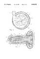
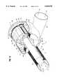
- FIG. 1is a left front perspective of the blood pump of the present invention
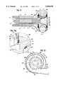
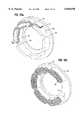
- FIG. 2is a fragmentary, cross-sectional view of the pump of FIG. 1, showing a plurality of ring magnets comprising part of the magnetic bearing assembly;
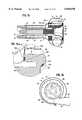
- FIG. 3is a fragmentary, cross-sectional view of the pump of FIG. 1, showing the shaft and an impeller;
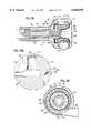
- FIG. 4is a view as in FIG. 1, but with the shaft and impeller shown removed from the housing;
- FIG. 5is a simplified, fragmentary, representation of a human heart, showing the pump implanted within the left ventricle of the heart;
- FIG. 6is a transverse, cross-sectional view of the housing, impeller, and impeller chamber, taken along the line 6--6, shown in FIG. 1;
- FIG. 7is a longitudinal, cross-sectional view of the pump, taken along the line 7--7, shown in FIG. 1;
- FIG. 8is a longitudinal, cross-sectional view of a simplified, schematic representation of the pump, showing respective polarities of the magnets and the pole pieces of the passive radial magnetic bearings, and the elements of the pump motor, including rotor magnets and a motor stator;
- FIG. 8ais a schematic view, similar to FIG. 8, but showing another embodiment of the present invention.
- FIG. 8bis a schematic view, similar to FIG. 8a, but showing another embodiment of the present invention.
- FIG. 9is a longitudinal, cross-sectional view of an impeller constructed in accordance with the principles of the present invention.
- FIG. 10is an end view thereof, taken from the right side of FIG. 9;
- FIG. 11is a longitudinal, cross-sectional view of a simplified, schematic representation of another embodiment of the pump.
- FIG. 11ais an enlarged view of the circled portion 11a from FIG. 11;
- FIG. 12is a cross-sectional end view of the FIG. 11 pump with the end of the housing and casing removed for clarity;
- FIG. 13is a perspective view, partially broken for clarity, of the blood pump of FIG. 11;
- FIG. 13ais a perspective view of a portion of FIG. 13, showing the slotted motor stator
- FIG. 13bis a perspective view, similar to FIG. 13a but showing a slotless motor stator.
- FIG. 14is another perspective view, partially broken for clarity, of the blood pump of FIG. 11;
- FIG. 15is a longitudinal, cross-sectional view of another embodiment of the pump.
- FIG. 15ais an enlarged view of the circled portion 15a from FIG. 15;
- FIG. 16is a cross-sectional end view of the FIG. 15 pump, with the end of the housing and casing removed for clarity;
- FIG. 17is a longitudinal, cross-sectional view of another embodiment of a blood pump.
- FIG. 17ais an enlarged view of the circled portion 17a from FIG. 17;
- FIG. 18is a cross-sectional end view of the FIG. 17 pump, with the end of the housing and casing removed for clarity;
- FIG. 19is a longitudinal, cross-sectional view of another embodiment of the present invention.
- FIG. 19ais an enlarged view of the circled portion 19a from FIG. 19;
- FIG. 20is a cross-sectional end view of the FIG. 19 pump, with the end of the housing and casing removed for clarity.
- a sealless rotary blood pump 11includes a housing 12, having an elongated inlet tube 13 and an impeller casing or volute 14.
- a discharge tube 16extends through the housing to communicate with the interior periphery of casing 14.
- Tube 16has a tangential orientation with respect to a radius of the casing, for effectively channeling the blood output from the pump.
- a pump rotor 17is located within housing 12, within casing 14, and includes an elongated, right-circular cylindrical support shaft or spindle 18, attached to a disc-shaped impeller 19. Rotor 17 is mounted for rotation about a longitudinal axis which extends both through shaft 18 and impeller 19. It should be noted that the preferred embodiment disclosed herein includes an impeller and a casing of centrifugal design. However, many of the structural features and aspects of operation of the present invention may also be adapted advantageously to rotary blood pumps of axial flow design.
- the pump 11 of the present inventionincludes a forward magnetic bearing 21 and a rearward magnetic bearing 22 to levitate rotor 17 and maintain it in proper radial alignment with respect to its longitudinal axis.
- a radial magnetic bearing constructionis shown in U.S. Pat. No. 4,072,370, issued to Wasson.
- the '370 Patentis hereby expressly incorporated by reference.
- the forward magnetic bearing 21 hereinmay be constructed entirely in accordance with the teachings of the '370 Patent. However, several simplifications and improvements to the construction shown in the '370 Patent are disclosed herein. For example, it has been determined that the radially polarized ring magnets (numerals 44 and 46) of the '370 device, are not necessary for successful practice of the invention herein.
- the axially magnetized ring magnets (numeral 22) of the '370 devicemay advantageously be replaced with axially magnetized disc magnets for purposes of the present invention.
- the forward magnetic bearing 21includes a plurality of rings, comprising ferromagnetic pole pieces 23 and axially polarized permanent magnets 24.
- pole pieces 23 and magnets 24are arranged in contingent, alternating fashion, and are located between outer sidewall 26 and inner sidewall 27 of inlet tube 13.
- the polarization of opposing magnetsis the same, inducing an identical polarization into a respective pole piece therebetween.
- a combination of high strength adhesive and surrounding tube sidewallsmaintains the arrangement of magnets and pole pieces in contingent relation, despite strong magnet forces attempting to urge the rings apart.
- Forward magnetic bearing 21also includes a plurality of discs, comprising ferromagnetic pole pieces 28 and axially polarized permanent magnets 29. Pole pieces 28 and magnets 29 are also arranged in contingent, alternating fashion, so as to form a magnetic structure which mirrors the polarity and axial position of respective pieces and magnets of the surrounding rings. This magnetic structure is first assembled and secured together using high strength adhesive, and is then installed within the hollow volume of shaft or spindle 17. The magnetic polarizations and repulsive forces produced by the magnets and the pole pieces of forward magnetic bearing 21 are such that magnetic levitation of support shaft 18 results.
- Bearing 22includes a first ring magnet 31 mounted on an outer wall of casing 14, and a second ring magnet 32 imbedded within a circular casing base 33. The bottom portion of casing 14 is attached and sealed to base 33, to form a fluid impervious enclosure for impeller 19 (see FIG. 7). Both magnets 31 and 32 are axially polarized, but each has a different polarization facing impeller 19.
- Bearing 22also includes a plurality of rod magnets 34, transversely extending from an upper face portion 36 to a lower face portion 37 of impeller 19. Rod magnets 34 are arranged in spaced, circular fashion, adjacent an outer periphery 38 of impeller 19.
- the polarizations between the ends of magnets 34 and the adjacent surfaces of magnets 31 and 32are respectively opposite, creating attractive, but equal and opposite magnetic forces acting on the impeller. It can be seen that radial movement of the impeller (deflection from the axis of rotation) will result in a restoring force due to the attraction between the magnets 34 towards magnets 31 and 32. The magnetic force in the axial direction will largely be counterbalanced to the opposing magnetic attraction of magnets 34 to magnet 31 and magnets 34 to magnet 32. However, the action of the magnetic force in the axial direction would not be restoring.
- magnets 34may be arcuate segments, rather than rods.
- the polarizations of the magnets 31, 32, and 34may be arranged to effect respective repulsive forces, rather than the attractive forces specifically disclosed herein. In this manner, referring to FIGS. 8a and 8b, the south pole of magnets 34 would be adjacent the south pole of magnet 31 and the north pole of magnets 34 would be adjacent the north pole of magnet 32. For the magnets to be restoring in the radial direction, the magnets would have to be offset. To this end, in the FIG.
- magnets 34would be more outward radially than magnets 31 and 32.
- magnets 34are radially inside the radial dimension of magnets 31 and 32. If a repulsive configuration is used, as illustrated in FIGS. 8a and 8b, the action of the magnetic force would be restoring in both the radial and axial direction.
- First thrust bearing 39includes a threaded plug 42, installed within casing base 33.
- Plug 42is screw adjustable along the longitudinal axis of rotor 17, and includes a recessed bearing surface 43.
- Surface 43is contoured to accommodate a corresponding bearing tip 44, in the lower face portion of impeller 19. It should be noted that the particular configuration of bearing 39 is not critical, and planar bearing surfaces may alternatively be used in this application.
- Second thrust bearing 41is secured within the blood entry end of inlet tube 13, and includes a spider 46, adjustment knob 47, and ball 48. Rotation of knob 47 will translate ball 48 along the longitudinal axis of rotor 17.
- second thrust bearing 41could be provided on the inner wall of casing 14, adjacent the upper face portion 36 of impeller 19. In this arrangement, portion 36 would slidably contact the annular thrust bearing surface.
- thrust bearings 39 and 41are effective not only to provide limit stops to axial movement of rotor 17, but also to adjust certain operational aspects of the pump.
- the upstream end of support shaft 18is shown in contact with ball 48.
- ball 48this will not always be the case during the course of operating the pump.
- the present inventiondoes not use a journal bearing to restrain the rotor.
- a journal bearingradially encases at least a portion of the rotor's support shaft or spindle. It is within this thin, annular volume between the shaft and the bearing surface, where thrombosis can occur in prior art devices as a consequence of heat and excessive residence time within the bearing.
- the bi-stable operation of the pump and rotor of the present inventioncontinuously flushes the blood around each thrust bearing, avoiding thrombosis effects of prior art journal bearings.
- second thrust bearing 41is effective to shift, or offset the rotor downstream a sufficient amount so the resultant, repulsive magnetic forces substantially counterbalance the hydrodynamic axial force produced by the rotating pump impeller.
- impeller 19includes a plurality of large blade sectors 49. Owing to its relatively high viscosity and susceptibility to damage from heat and mechanical action, blood is a uniquely difficult liquid to pump.
- one of the design considerations of the present inventionis to reduce such hemolysis, by minimizing the number of impeller blades and leading edges.
- blade sectors 49are made relatively wide or expansive through a rotational aspect (see FIG. 6). In other words, the outer periphery of each blade sector 49 assumes approximately 80 to 85 degrees of rotation. It should be noted that an alternative design contemplated herein includes only two blade sectors, each of which assumes approximately 175 degrees of rotation. In either case, the width of the impeller blade sectors of the present invention differ significantly from known prior art blades.
- the second modificationpertains to the thickness or height of the blade sectors.
- blade sectors 49are relatively thick in an axial direction.
- a narrow and deep impeller blood flow path or passageway 51is defined between adjacent edges of blade sectors 49.
- the size and configuration of the impeller bladesalso allows the structural integration of a number of features directly within the impeller 19.
- the previously discussed rearward magnetic bearing 22includes a plurality of rod magnets 34 of considerable length. Owing to the thickness of the blade sectors, these magnets are readily accommodated within the sectors.
- the sectorsmay also be provided with respective hollow chambers 52, to reduce the mass of the impeller and the gravity induced loads on the thrust bearings (see, FIG. 6).
- a brushless rotor motor 53includes arcuate magnetic segments 54, imbedded within the upper face portion 36 of blade sectors 49. As discussed above, the portions of segments 54 which would otherwise be in fluid communication with the pumped blood, are encased in a jacket or a coating (not shown) to prevent any chemical reaction between the blood and the magnetic segments.
- segments 54have alternating orientations in their polarities, and are directed toward an adjacent motor stator 56. Included within stator 56 are windings 57 and a circular pole piece or back iron 58, mounted on the outer surface of impeller casing 14. Windings 57 are interconnected by means of percutaneous wires to a controller 59 and a power supply 61, as shown in FIG. 5. Alternative to using wires, transcutaneous power transmission could be used. It is contemplated that controller 59 and power supply 61 may be worn externally by the user, or alternatively, they may be completely implanted in the user.
- Controller 59may include circuitry as simple as a variable voltage or current control, manually adjusted or programmed to determine the running rate of pump. However, controller 59 may also have interactive and automatic capabilities. For example, controller 59 may be interconnected to sensors on various organs of the user, automatically and instantaneously to tailor operation of the pump to the user's physical activity and condition.
- the windings 57are energized by the electrical output of controller 59 to produce an electromagnetic field.
- This fieldis concentrated by pole piece 58, and is effective to drive magnets 54 and the rotor 17, in rotary fashion.
- the back EMF resulting from the magnets 54 passing by the windingsis detected by the controller.
- the controlleruses this back EMF voltage to continue generation of the electromagnetic field in synchronism with further rotation of the rotor.
- Brushless operation of the motor 53is effected, then, by electromagnetic interaction between the stator and magnets imbedded within the pump's impeller blades.
- Motor 53with windings 57 and pole piece 58, together with magnets 54, function not only to transmit torque but also provide a restoring radial magnetic force that acts as a radial bearing.
- magnets 54are carried by blade sectors 49 and are positioned in radial alignment with pole piece 58.
- the magnets 54have attraction with the iron pole piece 58 of the stator. Any attempt to deflect the impeller radially produces an increasing restoring force between the pole piece 58 and the magnets 54 which would cause the impeller to return to a neutral position.
- Rotation of the rotor 17, including shaft 18 and impeller 19,causes blood to flow through inlet tube 13 in the direction of arrows 62.
- the bloodcontinues its path from the upper edge of passage 51 to the interior of casing 14.
- Discharge tube 16allows the blood to be expelled from the casing an into the user's cardiovascular system.
- FIG. 5Anatomical placement of the pump 11 is shown in FIG. 5.
- the simplified representation of a human heart 63includes a left ventricle 64 and an aorta 67.
- the inlet tube 16serves as the inflow cannula and is placed into the apex of the left ventricle 64.
- An arterial vascular graft 66is connected on one end to tube 16 and on the other end to the aorta 67 through an end to side anastomosis.
- the centrifugal design of the pumpallows a considerable amount of flexibility during implantation. Owing to the axial inflow and radial outflow of the pump, a 90 degree redirection of the blood is effected without the necessity of a flow-restrictive elbow fitting. Moreover, the pump can be rotated on its longitudinal axis to adjust the orientation of the discharge tube and minimize kinking and hydraulic losses in the vascular graft. Good anatomic compatibility is possible since the pump casing is compact and disc-shaped, fitting well between the apex of the heart and the adjacent diaphragm.
- blood flow path 62ais 0.06 inch to 0.1 inch in thickness.
- the fluid gap 70comprising the clearance between the impeller and the housing is 0.005 inch to 0.02 inch.
- the impeller diameteris 1.0 inch to 1.5 inch.
- the rotor diameteris 0.025 inch to 0.4 inch.
- the outside diameter of the flow annulusis 0.35 inch to 0.55 inch.
- the outer diameter of the housing adjacent the forward end of the pumpis 0.85 inch to 1.25 inch.
- the axial length of the entire pumpis 1.75 inch to 3.0 inch.
- the axial length of the rotor spindleis 1.0 inch to 1.5 inch and the axial length of the impeller is 0.2 inch to 0.5 inch.
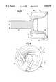
- FIGS. 9 and 10Enlarged views of an impeller used in the pump of the present invention are set forth in FIGS. 9 and 10.
- an impeller 74is shown therein having a number of blade sectors 76, 78 and 80.
- Blade sectors 76 and 78are separated by slot 82; blade sectors 78 and 80 are separated by slot 84; and blade sectors 80 and 76 are separated by slot 86.
- blade sectors 76, 78 and 80that are relatively thick in the axial direction, narrow and deep impeller blood flow paths are formed by slots 82, 84 and 86 between the adjacent edges of the blade sectors.
- the ratio between the area of working surface of the blades and the volume of the passagewayis increased.
- the average distance of the liquid in the passageway from the working surface of the bladesis decreased. Both of these beneficial results allow a small pump for blood which has less blades for potentially damaging blood, yet the small pump maintains acceptable efficiency.
- the diameter of the impelleris 1 inch to 1.5 inch
- the blade depth bd (FIG. 9)is 0.2 inch to 0.5 inch
- the magnet width mw (FIG. 9)is 0.15 inch to 0.3 inch
- the spindle diameter sd (FIG. 9)is 0.25 inch to 0.5 inch
- the inner diameter id (FIG. 9) of the impeller inletis 0.45 inch to 0.6 inch.
- the width w of the slotsis approximately 0.075 inch and preferably ranges from 0.05 inch to 0.2 inch.
- the outlet angle a (FIG. 10)preferably ranges between 30° and 90°.
- the blood pump 11' shown thereinis similar in many respects to blood pump 11 illustrated in FIGS. 1-8, and includes housing 12 having an elongated inlet tube 13 and a scroll-shaped impeller casing or volute 14.
- a discharge tube 16extends through the housing to communicate with the interior periphery of casing 14. Tube 16 has a tangential orientation with respect to a radius of the casing, for effectively channeling the blood output from the pump.
- Pump rotor 17is located within housing 12, within casing 14, and includes an elongated, right-circular cylindrical support shaft or spindle 18, attached to impeller 74. Rotor 17 is mounted for rotation about an longitudinal axis which extends both through shaft 18 and impeller 74.
- the magnetic bearings for levitating rotor 17 and maintaining it in proper radial alignment with respect to its longitudinal axisare not specifically shown but may be identical to those illustrated in the pump embodiment of FIGS. 1-8 and described above.
- a first motor stator 90comprising conductive coils or motor windings 91, is located at the rear of impeller 74.
- a ring of back iron 92is located behind windings 91 and, as illustrated in FIG. 9, first motor stator 90 and back iron 92 are fixed between housing 12 and casing 14.
- a second motor stator 94comprising windings 95, is positioned on the forward side of impeller 74.
- windings 95are fixed to casing 14 and a ring of back iron 96 is positioned forward of windings 95.
- back iron 92 and back iron 96have teeth 98 which extend into the stator windings to form the stator iron.
- the windings 95wrap around the teeth 98 in the intervening slots 99 (See FIG. 13a).
- a slotless motor statoris illustrated.
- the windings 91are fixed to the back iron 96 and there are no teeth extending into the stator windings.
- the motor stators 90 and 94are placed on opposite sides of casing 14 such that each is adjacent to the pole faces of the motor rotor magnets 98.
- Back iron 92 and back iron 96serve to complete a magnetic circuit.
- the windings 91 and 95 of the stators 90, 94can be in series or each stator 90, 94 can be commutated independent of the other.
- the radial restoring force which results from the attractive force of the motor rotor magnets to the motor statorswill be nearly twice as large as the restoring force with only one stator.
- the total volume and weight of the motorwill be smaller than a single stator design.
- the dual stator designis adapted to provide system redundancy for a fail safe mode, since each stator can be made to operate independently of the other in the case of a system failure.
- hydrodynamic bearingscan be located on the surface of the impeller to constrain axial motion and to provide radial support in the case of eccentric motion or shock on the device.
- hydrodynamic bearings in the form of raised pads 100, 101 and contact surfaces 102 and 103are illustrated.
- Such hydrodynamic bearingsare symmetrically located about the impeller as illustrated in FIG. 13, in which raised pads 100 are shown.
- the raised padscould be rectangularly-shaped or wedge-shaped and are preferably formed of hardened or wear resistant materials such as ceramics, diamond coatings or titanium nitride. Alternatively, the raised pads may be formed of a different material having an alumina or other ceramic coating or insert.
- the raised padsare carried by either the impeller or the casing, or an attachment to the casing.
- the raised pads 100are carried by the impeller and the raised pads 101 are carried by a cup-shaped member 104 that is fastened to the casing.
- Cup-shaped member 104is utilized as a reinforcement for the casing which would not be structurally stable enough to carry the raised pads itself.
- the hydrodynamic bearingsare formed by a raised pad spaced from a contact surface by the blood gap. Although at rest there may be contact between the impeller and the casing, once rotation begins each hydrodynamic bearing is structured so that during relative movement between the raised pad and the contact surface the hydrodynamic action of the fluid film produces increased pressure within the bearing gap which forces the raised pad and the contact surface apart.
- the hydrodynamic bearingscan aid in axial support, radial support or both axial and radial support.
- the bearingsare perpendicular to the rotational axis, they aid primarily in axial support but if they are at an angle with respect to the rotational axis, they aid in both radial and axial support.
- the hydrodynamic bearingsare positioned outside the axis of rotation, as illustrated.
- stator 90there is a single axial motor and the stator 90 is located at the rear end of impeller 74.
- Stator 90comprises windings 91, and a ring of back iron 92 is located downstream of windings 91.
- the motor stator 90 and back ironare fixed between casing 14 and housing 12.
- a ring of back iron 106is placed in the impeller, in axial alignment with the magnets, such that it completes the flux return path for the motor rotor magnets in the impeller.
- motor stator 90 and back iron 92are located downstream of the impeller and outside of casing 12, back iron 106 is located within the impeller and within the casing 12. Using back iron to complete the magnetic circuit in this manner increases the overall efficiency of the motor.
- a motor stator 90 and back iron 92are provided at the rear end of impeller 74 as with the FIGS. 9-14 embodiments, but another ring of back iron 108 is placed outside pump casing 12 on the front side of the impeller and is fixed to the casing.
- Back iron ring 108serves two purposes. First, it serves to help complete the flux return path for the motor rotor magnets. Second, the attractive force between the motor rotor magnets and the ring of back iron 108 substantially reduces the net axial force produced by the attraction of the motor rotor magnets for the stator iron. Third, the ring of back iron significantly increases the radial restoring force compared to just the interaction between the motor rotor magnets and the stator iron.
- FIGS. 1-18 embodimentsutilize an axial flux gap motor
- a radial flux gap motoris utilized.
- a ring-shaped structureis placed on either side of the impeller to house a series of motor rotor magnets (an even number) oriented such that the magnetic poles of the motor rotor magnets are radially, and alternately, aligned.
- the inner diameter of the magnetsis located on the surface of a ring of back iron to provide a flux return path.
- passive radial magnetic bearingsare used on the opposite end of the impeller.
- the motor rotor magnets 110are radially aligned. Radially within the motor rotor magnets 110 is a ring of back iron 112. The inner diameter of magnets 110 are located on the surface of back iron ring 112 (see FIG. 20) to provide a flux return path. The motor rotor magnets 110 and ring of back iron 112 are carried by the impeller, within the casing 14. Outside of the casing 14 there is radially positioned a ring-shaped stator 114 with motor windings 116.
- a number of axial permanent magnets 120are carried by the impeller, at its rear end.
- a number of axial permanent magnets 122are fixed to the casing 14 and housing 12, downstream of and partially offset from, magnets 120. Magnets 120 and 122 serve as passive magnetic bearings for the impeller.
- FIGS. 11-20 embodimentsVarious elements from the FIGS. 1-8 embodiment can be used in the FIGS. 11-20 embodiments.
- magnets 34 illustrated in FIGS. 3 and 4could be used in impeller 74 of the FIGS. 11-20 embodiments.
- rotor 18 of the FIGS. 11-20 embodimentscould be supported using front thrust bearings such as thrust bearing 41 of the FIGS. 1-8 embodiment.
- FIGS. 11-20 embodiments from the FIGS. 1-8 embodimentVarious other elements may be employed in the FIGS. 11-20 embodiments from the FIGS. 1-8 embodiment.
Landscapes
- Health & Medical Sciences (AREA)
- Engineering & Computer Science (AREA)
- Heart & Thoracic Surgery (AREA)
- Cardiology (AREA)
- Mechanical Engineering (AREA)
- Veterinary Medicine (AREA)
- Life Sciences & Earth Sciences (AREA)
- Public Health (AREA)
- General Health & Medical Sciences (AREA)
- Animal Behavior & Ethology (AREA)
- Anesthesiology (AREA)
- Biomedical Technology (AREA)
- Hematology (AREA)
- Power Engineering (AREA)
- Physics & Mathematics (AREA)
- General Engineering & Computer Science (AREA)
- Medical Informatics (AREA)
- Fluid Mechanics (AREA)
- Chemical & Material Sciences (AREA)
- Combustion & Propulsion (AREA)
- Electromagnetism (AREA)
- Vascular Medicine (AREA)
- External Artificial Organs (AREA)
- Structures Of Non-Positive Displacement Pumps (AREA)
Abstract
Description
Claims (34)
Priority Applications (14)
| Application Number | Priority Date | Filing Date | Title |
|---|---|---|---|
| US08/910,375US5840070A (en) | 1996-02-20 | 1997-08-13 | Sealless rotary blood pump |
| IL12487698AIL124876A (en) | 1997-08-13 | 1998-06-11 | Sealless rotary blood pump |
| CA002240555ACA2240555A1 (en) | 1997-08-13 | 1998-06-12 | Sealless rotary blood pump |
| US09/108,434US6080133A (en) | 1996-02-20 | 1998-07-01 | Sealless rotary blood pump |
| DE69828926TDE69828926T2 (en) | 1997-08-13 | 1998-07-13 | Sealless rotary blood pump |
| EP98113010AEP0901797B1 (en) | 1997-08-13 | 1998-07-13 | Sealless rotary blood pump |
| AT98113010TATE288770T1 (en) | 1997-08-13 | 1998-07-13 | SEALLESS ROTARY BLOOD PUMP |
| JP20598598AJP4248626B2 (en) | 1997-08-13 | 1998-07-22 | No seal blood pump |
| AU79936/98AAU730235C (en) | 1996-02-20 | 1998-08-12 | Sealless rotary blood pump |
| KR1019980032825AKR19990023563A (en) | 1997-08-13 | 1998-08-13 | Non-sealed rotating blood pump |
| US09/420,997US6234998B1 (en) | 1996-02-20 | 1999-10-20 | Sealless rotary blood pump |
| US09/689,251US6368083B1 (en) | 1996-02-20 | 2000-10-13 | Sealless rotary blood pump |
| US10/034,873US6688861B2 (en) | 1996-02-20 | 2001-12-26 | Sealless rotary blood pump |
| US10/887,116US7575423B2 (en) | 1996-02-20 | 2004-02-02 | Sealless rotary blood pump |
Applications Claiming Priority (2)
| Application Number | Priority Date | Filing Date | Title |
|---|---|---|---|
| US08/603,536US5695471A (en) | 1996-02-20 | 1996-02-20 | Sealless rotary blood pump with passive magnetic radial bearings and blood immersed axial bearings |
| US08/910,375US5840070A (en) | 1996-02-20 | 1997-08-13 | Sealless rotary blood pump |
Related Parent Applications (1)
| Application Number | Title | Priority Date | Filing Date |
|---|---|---|---|
| US08/603,536Continuation-In-PartUS5695471A (en) | 1996-02-20 | 1996-02-20 | Sealless rotary blood pump with passive magnetic radial bearings and blood immersed axial bearings |
Related Child Applications (2)
| Application Number | Title | Priority Date | Filing Date |
|---|---|---|---|
| US08/603,536DivisionUS5695471A (en) | 1996-02-20 | 1996-02-20 | Sealless rotary blood pump with passive magnetic radial bearings and blood immersed axial bearings |
| US09/108,434DivisionUS6080133A (en) | 1996-02-20 | 1998-07-01 | Sealless rotary blood pump |
Publications (1)
| Publication Number | Publication Date |
|---|---|
| US5840070Atrue US5840070A (en) | 1998-11-24 |
Family
ID=25428690
Family Applications (6)
| Application Number | Title | Priority Date | Filing Date |
|---|---|---|---|
| US08/910,375Expired - LifetimeUS5840070A (en) | 1996-02-20 | 1997-08-13 | Sealless rotary blood pump |
| US09/108,434Expired - LifetimeUS6080133A (en) | 1996-02-20 | 1998-07-01 | Sealless rotary blood pump |
| US09/420,997Expired - LifetimeUS6234998B1 (en) | 1996-02-20 | 1999-10-20 | Sealless rotary blood pump |
| US09/689,251Expired - LifetimeUS6368083B1 (en) | 1996-02-20 | 2000-10-13 | Sealless rotary blood pump |
| US10/034,873Expired - LifetimeUS6688861B2 (en) | 1996-02-20 | 2001-12-26 | Sealless rotary blood pump |
| US10/887,116Expired - Fee RelatedUS7575423B2 (en) | 1996-02-20 | 2004-02-02 | Sealless rotary blood pump |
Family Applications After (5)
| Application Number | Title | Priority Date | Filing Date |
|---|---|---|---|
| US09/108,434Expired - LifetimeUS6080133A (en) | 1996-02-20 | 1998-07-01 | Sealless rotary blood pump |
| US09/420,997Expired - LifetimeUS6234998B1 (en) | 1996-02-20 | 1999-10-20 | Sealless rotary blood pump |
| US09/689,251Expired - LifetimeUS6368083B1 (en) | 1996-02-20 | 2000-10-13 | Sealless rotary blood pump |
| US10/034,873Expired - LifetimeUS6688861B2 (en) | 1996-02-20 | 2001-12-26 | Sealless rotary blood pump |
| US10/887,116Expired - Fee RelatedUS7575423B2 (en) | 1996-02-20 | 2004-02-02 | Sealless rotary blood pump |
Country Status (8)
| Country | Link |
|---|---|
| US (6) | US5840070A (en) |
| EP (1) | EP0901797B1 (en) |
| JP (1) | JP4248626B2 (en) |
| KR (1) | KR19990023563A (en) |
| AT (1) | ATE288770T1 (en) |
| CA (1) | CA2240555A1 (en) |
| DE (1) | DE69828926T2 (en) |
| IL (1) | IL124876A (en) |
Cited By (135)
| Publication number | Priority date | Publication date | Assignee | Title |
|---|---|---|---|---|
| US6071093A (en)* | 1996-10-18 | 2000-06-06 | Abiomed, Inc. | Bearingless blood pump and electronic drive system |
| WO2000032257A1 (en)* | 1998-12-03 | 2000-06-08 | Kriton Medical, Inc. | Active magnetic bearing system for blood pump |
| US6074180A (en)* | 1996-05-03 | 2000-06-13 | Medquest Products, Inc. | Hybrid magnetically suspended and rotated centrifugal pumping apparatus and method |
| WO2000038757A1 (en) | 1998-12-28 | 2000-07-06 | Kriton Medical, Inc. | Rotary blood pump with ceramic members |
| FR2789316A1 (en)* | 1999-02-09 | 2000-08-11 | Vascor Inc | IMPLANTABLE BLOOD PUMP |
| US6116862A (en)* | 1996-06-25 | 2000-09-12 | Medos Medizintechnik Gmbh | Blood pump |
| WO2000064508A1 (en) | 1999-04-28 | 2000-11-02 | Kriton Medical, Inc. | Rotary blood pump |
| US6201329B1 (en)* | 1997-10-27 | 2001-03-13 | Mohawk Innovative Technology, Inc. | Pump having magnetic bearing for pumping blood and the like |
| US6227817B1 (en)* | 1999-09-03 | 2001-05-08 | Magnetic Moments, Llc | Magnetically-suspended centrifugal blood pump |
| US6234998B1 (en)* | 1996-02-20 | 2001-05-22 | Kriton Medical, Inc. | Sealless rotary blood pump |
| US6244835B1 (en)* | 1996-06-26 | 2001-06-12 | James F. Antaki | Blood pump having a magnetically suspended rotor |
| US6245007B1 (en) | 1999-01-28 | 2001-06-12 | Terumo Cardiovascular Systems Corporation | Blood pump |
| WO2001054749A3 (en)* | 2000-01-27 | 2001-12-13 | A Med Systems Inc | Cannulation system and related methods |
| GB2365346A (en)* | 1999-02-09 | 2002-02-20 | Vascor Inc | Magnetically suspended blood pump |
| US6394769B1 (en) | 1996-05-03 | 2002-05-28 | Medquest Products, Inc. | Pump having a magnetically suspended rotor with one active control axis |
| US6499881B2 (en)* | 1999-01-15 | 2002-12-31 | Zine Eddine Boutaghou | Hydrodynamic bearings and boundary lubricated system with DLC bumps |
| US20030023131A1 (en)* | 2001-06-06 | 2003-01-30 | Antaki James F. | Apparatus and method for reducing heart pump backflow |
| US20030023255A1 (en)* | 2001-06-29 | 2003-01-30 | Miles Scott D. | Cannulation apparatus and method |
| WO2003016718A1 (en)* | 2001-08-21 | 2003-02-27 | Advanced Rotary Systems, Llc | Integrated motorized pump |
| US6530876B1 (en) | 2000-04-25 | 2003-03-11 | Paul A. Spence | Supplemental heart pump methods and systems for supplementing blood through the heart |
| US20030091450A1 (en)* | 2001-11-13 | 2003-05-15 | Davis William D. | Pump with electrodynamically supported impeller |
| US20030130668A1 (en)* | 2001-06-29 | 2003-07-10 | Nieman Timothy R. | Endoscopic cannulation apparatus and method |
| US6613008B2 (en) | 2000-06-13 | 2003-09-02 | A-Med Systems, Inc. | Integrated system for cardiopulmonary bypass and related methods |
| US20030205233A1 (en)* | 1999-12-02 | 2003-11-06 | A-Med Systems, Inc. | Surgical drape and panel assembly |
| US20030233144A1 (en)* | 2002-06-13 | 2003-12-18 | Antaki James F. | Low profile inlet for an implantable blood pump |
| US20040028525A1 (en)* | 1997-09-05 | 2004-02-12 | Woodard John C. | Rotary pump with exclusively hydrodynamically suspended impeller |
| US20040030216A1 (en)* | 1997-09-05 | 2004-02-12 | Woodard John Campbell | Rotary pump with hydrodynamically suspended impeller |
| US20040046467A1 (en)* | 2000-11-10 | 2004-03-11 | Delta Electronics Inc. | Magnetic bearing assembly |
| US6746474B2 (en) | 2002-05-31 | 2004-06-08 | Vahid Saadat | Apparatus and methods for cooling a region within the body |
| US6808508B1 (en)* | 2000-09-13 | 2004-10-26 | Cardiacassist, Inc. | Method and system for closed chest blood flow support |
| US20040228724A1 (en)* | 2001-03-14 | 2004-11-18 | Capone Christopher D. | Touch down of blood pump impellers |
| US20050025630A1 (en)* | 1999-04-23 | 2005-02-03 | Ayre Peter Joseph | Rotary blood pump and control system therefor |
| US6879126B2 (en) | 2001-06-29 | 2005-04-12 | Medquest Products, Inc | Method and system for positioning a movable body in a magnetic bearing system |
| US20050084399A1 (en)* | 2003-09-18 | 2005-04-21 | Wampler Richard K. | Rotary blood pump |
| US20050096496A1 (en)* | 2003-10-31 | 2005-05-05 | Spence Paul A. | Methods, devices and systems for counterpulsation of blood flow to and from the circulatory system |
| US20050147512A1 (en)* | 2003-10-03 | 2005-07-07 | Foster-Miller, Inc. | Rotary pump with electromagnetic LCR bearing |
| US20050184609A1 (en)* | 2004-02-20 | 2005-08-25 | Delta Electronics, Inc. | Motor and magnetic bearing assembly thereof |
| US20050234287A1 (en)* | 2004-04-15 | 2005-10-20 | Paul Weatherbee | Pulsatile blood pumping system |
| US20060024182A1 (en)* | 2004-03-18 | 2006-02-02 | Mustafa Akdis | Pump |
| US20060122456A1 (en)* | 2004-12-03 | 2006-06-08 | Larose Jeffrey A | Wide blade, axial flow pump |
| US20060245959A1 (en)* | 2005-04-29 | 2006-11-02 | Larose Jeffrey A | Multiple rotor, wide blade, axial flow pump |
| US20070053781A1 (en)* | 2003-05-15 | 2007-03-08 | Davis William D | Pump with electrodynamically supported impeller |
| US20070078293A1 (en)* | 2005-10-05 | 2007-04-05 | Shambaugh Charles R Jr | Impeller for a rotary ventricular assist device |
| US20070106274A1 (en)* | 2005-10-19 | 2007-05-10 | Ayre Peter J | Control systems for implantable medical devices |
| US20070142696A1 (en)* | 2005-12-08 | 2007-06-21 | Ventrassist Pty Ltd | Implantable medical devices |
| US20070156006A1 (en)* | 2005-06-06 | 2007-07-05 | The Cleveland Clinic Foundation And Foster-Miller, Inc. | Blood pump |
| US20070161847A1 (en)* | 2001-05-21 | 2007-07-12 | Woodard John C | Staged implantation of ventricular assist devices |
| US20070161845A1 (en)* | 2006-01-09 | 2007-07-12 | Cardiacassist, Inc. | Percutaneous right ventricular assist apparatus and method |
| US20070197854A1 (en)* | 2006-01-27 | 2007-08-23 | Circulite, Inc. | Heart assist system |
| US20070252542A1 (en)* | 1999-07-08 | 2007-11-01 | Heartware, Inc. | Method and apparatus for controlling brushless DC motors in implantable medical devices |
| US20070276480A1 (en)* | 2003-10-09 | 2007-11-29 | Tansley Geoffrey D | Impeller |
| US20080008609A1 (en)* | 2006-07-06 | 2008-01-10 | Pate Thomas D | Positive displacement pump system and method |
| US20080021394A1 (en)* | 2006-01-13 | 2008-01-24 | Larose Jeffrey A | Stabilizing drive for contactless rotary blood pump impeller |
| US20080076960A1 (en)* | 2006-08-30 | 2008-03-27 | Circulite, Inc. | Cannula insertion devices, systems, and methods including a compressible member |
| US20080076959A1 (en)* | 2006-08-30 | 2008-03-27 | Circulite, Inc. | Devices, methods and systems for establishing supplemental blood flow in the circulatory system |
| WO2008017289A3 (en)* | 2006-08-06 | 2008-04-03 | Mustafa Akdis | Blood pump |
| US20080200750A1 (en)* | 2006-11-17 | 2008-08-21 | Natalie James | Polymer encapsulation for medical device |
| US20080234623A1 (en)* | 2005-08-18 | 2008-09-25 | Ilias-Medical Gmbh | Device For Enriching And/Or Depleting Materials In A Liquid |
| US20080240947A1 (en)* | 1996-05-03 | 2008-10-02 | World Heart, Inc. | Implantable centrifugal blood pump with hybrid magnetic bearings |
| US20090023975A1 (en)* | 2007-07-19 | 2009-01-22 | Circulite, Inc. | Cannula for heart chamber implantation and related systems and methods |
| JP2009018192A (en)* | 2008-10-01 | 2009-01-29 | Heartware Inc | Sealless blood pump with thrombosis prevention means |
| CZ300147B6 (en)* | 2007-08-10 | 2009-02-25 | Vysoké ucení technické v Brne | Glandless centrifugal pump with integrated disk-type motor |
| US20090112050A1 (en)* | 2007-10-24 | 2009-04-30 | Circulite, Inc. | Transseptal cannula, tip, delivery system, and method |
| US20090171137A1 (en)* | 2006-09-14 | 2009-07-02 | Circulite, Inc. | Intravascular blood pump and catheter |
| US20090182188A1 (en)* | 2006-08-30 | 2009-07-16 | Circulite, Inc. | Devices, methods and systems for establishing supplemental blood flow in the circulatory system |
| US20090203957A1 (en)* | 2008-02-08 | 2009-08-13 | Larose Jeffrey A | Ventricular assist device for intraventricular placement |
| US20090306492A1 (en)* | 2005-07-12 | 2009-12-10 | Nicholas Andrew Earl | Restraining device for a percutaneous lead assembly |
| US20100036487A1 (en)* | 2006-10-27 | 2010-02-11 | Ventrassist Pty. Ltd. | Blood Pump With An Ultrasound Transducer |
| US7699588B2 (en) | 2003-07-04 | 2010-04-20 | Jostra Ag | Centrifugal pump |
| US20100106225A1 (en)* | 2003-08-01 | 2010-04-29 | Ventracor Limited | Transcutaneous Power And/Or Data Transceiver |
| US20100174231A1 (en)* | 2009-01-07 | 2010-07-08 | Cleveland Clinic Foundation | Method for physiologic control of a continuous flow total artificial heart |
| US20100249491A1 (en)* | 2009-03-27 | 2010-09-30 | Circulite, Inc. | Two-piece transseptal cannula, delivery system, and method of delivery |
| US20100249490A1 (en)* | 2009-03-27 | 2010-09-30 | Circulite, Inc. | Transseptal cannula device, coaxial balloon delivery device, and methods of using the same |
| US20100268333A1 (en)* | 2009-04-16 | 2010-10-21 | Gohean Jeffrey R | System and method for controlling pump |
| US20100266423A1 (en)* | 2009-04-16 | 2010-10-21 | Gohean Jeffrey R | System and Method for Pump with Deformable Bearing Surface |
| US20100268334A1 (en)* | 2009-04-16 | 2010-10-21 | Pate Thomas D | System and Method for Pump Variable Stroke |
| US20100266422A1 (en)* | 2009-04-16 | 2010-10-21 | Pate Thomas D | Positive Displacement Pump System and Method with Rotating Valve |
| US20110112353A1 (en)* | 2009-11-09 | 2011-05-12 | Circulite, Inc. | Bifurcated outflow cannulae |
| US20110160517A1 (en)* | 2009-12-31 | 2011-06-30 | Cardiacassist, Inc. | System for heart assist, cannula and method |
| US7993260B2 (en) | 1997-10-09 | 2011-08-09 | Thoratec Corporation | Implantable heart assist system and method of applying same |
| US20110237863A1 (en)* | 2008-09-26 | 2011-09-29 | WorldHeart, Inc. | Magnetically-levitated blood pump with optimization method enabling miniaturization |
| US8353686B2 (en) | 2004-10-18 | 2013-01-15 | Thoratec Corporation | Rotor stability of a rotary pump |
| US8672611B2 (en) | 2006-01-13 | 2014-03-18 | Heartware, Inc. | Stabilizing drive for contactless rotary blood pump impeller |
| WO2014140282A1 (en)* | 2013-03-15 | 2014-09-18 | Milux Holding S.A. | Operable implant comprising an electrical motor and a gear system |
| US8905910B2 (en) | 2010-06-22 | 2014-12-09 | Thoratec Corporation | Fluid delivery system and method for monitoring fluid delivery system |
| US20150023803A1 (en)* | 2013-03-14 | 2015-01-22 | Circulite, Inc. | Magnetically levitated and driven blood pump and method for using the same |
| US9089635B2 (en) | 2010-06-22 | 2015-07-28 | Thoratec Corporation | Apparatus and method for modifying pressure-flow characteristics of a pump |
| US9107992B2 (en) | 2011-11-28 | 2015-08-18 | MI-VAD, Inc. | Ventricular assist device and method |
| CN105797226A (en)* | 2016-03-14 | 2016-07-27 | 正仁(北京)医疗仪器有限公司 | Magnetic suspension roller type heart pump |
| US9463268B2 (en) | 2010-09-07 | 2016-10-11 | Paul A. Spence | Cannula systems and methods |
| US9512852B2 (en) | 2006-03-31 | 2016-12-06 | Thoratec Corporation | Rotary blood pump |
| DE112005001144B4 (en)* | 2004-03-18 | 2017-02-02 | Medos Medizintechnik Ag | pump |
| US9585991B2 (en) | 2012-10-16 | 2017-03-07 | Heartware, Inc. | Devices, systems, and methods for facilitating flow from the heart to a blood pump |
| US20170102001A1 (en)* | 2014-03-24 | 2017-04-13 | Heraeus Deutschland GmbH & Co. KG | Pump housing made from at least three different sinterable materials |
| US20170281842A1 (en)* | 2016-04-01 | 2017-10-05 | Heartware, Inc. | Axial flow blood pump with radially offset rotor |
| US9808283B2 (en) | 2013-12-04 | 2017-11-07 | Heartware, Inc. | Apparatus and methods for cutting an atrial wall |
| WO2017120449A3 (en)* | 2016-01-06 | 2017-11-16 | Bivacor Inc. | Heart pump |
| US9845829B2 (en)* | 2013-10-17 | 2017-12-19 | Skf Magnetic Mechatronics | Radial magnetic bearing and method of manufacture |
| US9872976B2 (en) | 2010-08-20 | 2018-01-23 | Thoratec Corporation | Assembly and method for stabilizing a percutaneous cable |
| US20180245596A1 (en)* | 2016-07-26 | 2018-08-30 | RELIAX MOTORES SA de CV | Integrated electric motor and pump assembly |
| US20180252228A1 (en)* | 2015-08-25 | 2018-09-06 | Reinheart Gmbh | Active magnetic bearing |
| US10077777B2 (en) | 2014-05-09 | 2018-09-18 | The Cleveland Clinic Foundation | Artificial heart system implementing suction recognition and avoidance methods |
| US10377097B2 (en)* | 2016-06-20 | 2019-08-13 | Terumo Cardiovascular Systems Corporation | Centrifugal pumps for medical uses |
| US10426880B2 (en) | 2014-02-25 | 2019-10-01 | MI-VAD, Inc. | Ventricular assist device and method |
| US10514044B2 (en) | 2013-06-21 | 2019-12-24 | Heraeus Deutschland GmbH & Co. KG | Pump housing of two different sinterable materials |
| US10539140B2 (en) | 2013-06-21 | 2020-01-21 | Heraeus Deutschland GmbH & Co. KG | Pump housing of a magnetic and a non-magnetic material |
| EP3633217A1 (en)* | 2018-10-02 | 2020-04-08 | Berlin Heart GmbH | Bearing assembly and rotation fluid pump |
| US10660996B2 (en) | 2014-06-10 | 2020-05-26 | Calon Cardio-Technology Ltd. | Cardiac pump |
| US10905807B2 (en) | 2017-07-13 | 2021-02-02 | CORVION, Inc. | High efficiency blood pump |
| US10947986B2 (en)* | 2018-07-11 | 2021-03-16 | Ch Biomedical (Usa) Inc. | Compact centrifugal pump with magnetically suspended impeller |
| US20210268262A1 (en)* | 2018-06-11 | 2021-09-02 | Universität Zürich | Blood pump for mechanical circulatory support for fontan patients |
| US11191946B2 (en)* | 2020-03-06 | 2021-12-07 | CorWave SA | Implantable blood pumps comprising a linear bearing |
| US20220072296A1 (en)* | 2019-06-19 | 2022-03-10 | Terumo Kabushiki Kaisha | Pump device for pumping blood |
| US11292014B2 (en) | 2015-04-05 | 2022-04-05 | Arteriocyte Medical Systems, Inc. | Centrifuge counterbalance with adjustable center of gravity and methods for using the same |
| US11298522B2 (en) | 2016-04-11 | 2022-04-12 | CorWave SA | Implantable pump system having an undulating membrane |
| US11415150B2 (en)* | 2018-05-28 | 2022-08-16 | Berlin Heart Gmbh | Fluid pump |
| US11471664B2 (en)* | 2017-08-29 | 2022-10-18 | Rocketheart Technology Co. Ltd | Blood pump device |
| US11512689B2 (en) | 2017-11-10 | 2022-11-29 | CorWave SA | Undulating-membrane fluid circulator |
| CN115531716A (en)* | 2022-10-21 | 2022-12-30 | 重庆凯磁智能科技研究院有限公司 | Mixed magnetic blood pump |
| US11654274B2 (en) | 2017-04-05 | 2023-05-23 | Bivacor Inc. | Heart pump drive and bearing |
| US11672968B2 (en)* | 2017-08-11 | 2023-06-13 | Carnegie Mellon University | Blood-immersed bearing system for a blood pump |
| US11712501B2 (en) | 2019-11-12 | 2023-08-01 | Fresenius Medical Care Deutschland Gmbh | Blood treatment systems |
| US11712554B2 (en) | 2016-04-11 | 2023-08-01 | CorWave SA | Implantable pump system having a coaxial ventricular cannula |
| US11730871B2 (en) | 2019-11-12 | 2023-08-22 | Fresenius Medical Care Deutschland Gmbh | Blood treatment systems |
| US11752247B2 (en) | 2019-11-12 | 2023-09-12 | Fresenius Medical Care Deutschland Gmbh | Blood treatment systems |
| US20230302271A1 (en)* | 2012-02-16 | 2023-09-28 | Abiomed Europe Gmbh | Intravascular blood pump |
| US11786719B2 (en)* | 2018-07-24 | 2023-10-17 | Cardiacassist, Inc. | Rotary blood pump |
| US11925736B2 (en) | 2019-11-12 | 2024-03-12 | Fresenius Medical Care Deutschland Gmbh | Blood treatment systems |
| US12017059B2 (en) | 2022-11-15 | 2024-06-25 | CorWave SA | Implantable heart pump systems including an improved apical connector and/or graft connector |
| US12104600B2 (en) | 2007-02-27 | 2024-10-01 | Miracor Medical Sa | Device to assist the performance of a heart |
| US12214182B2 (en) | 2017-11-29 | 2025-02-04 | CorWave SA | Implantable pump system having an undulating membrane with improved hydraulic performance |
| US12251550B2 (en) | 2022-04-26 | 2025-03-18 | CorWave SA | Blood pumps having an encapsulated actuator |
| US12257427B2 (en) | 2022-11-15 | 2025-03-25 | CorWave SA | Implantable heart pump systems including an improved apical connector and/or graft connector |
| US12285553B2 (en) | 2019-11-12 | 2025-04-29 | Fresenius Medical Care Deutschland Gmbh | Blood treatment systems |
| US12329890B2 (en) | 2019-11-12 | 2025-06-17 | Fresenius Medical Care Deutschland Gmbh | Blood treatment systems |
Families Citing this family (176)
| Publication number | Priority date | Publication date | Assignee | Title |
|---|---|---|---|---|
| US5957672A (en)* | 1993-11-10 | 1999-09-28 | The United States Of America As Represented By The Administrator Of The National Aeronautics And Space Administration | Blood pump bearing system |
| DE29821565U1 (en)* | 1998-12-02 | 2000-06-15 | Impella Cardiotechnik AG, 52074 Aachen | Bearingless blood pump |
| US6506025B1 (en)* | 1999-06-23 | 2003-01-14 | California Institute Of Technology | Bladeless pump |
| US6227820B1 (en)* | 1999-10-05 | 2001-05-08 | Robert Jarvik | Axial force null position magnetic bearing and rotary blood pumps which use them |
| AT412065B (en)* | 2000-03-24 | 2004-09-27 | Schima Heinrich Dr | ROTATIONAL PUMP WITH HYDRAULICALLY BEARED ROTOR |
| DE10108810A1 (en)* | 2001-02-16 | 2002-08-29 | Berlin Heart Ag | Device for the axial conveyance of liquids |
| DE10123138B4 (en)* | 2001-04-30 | 2007-09-27 | Berlin Heart Ag | Method for position control of a permanently magnetically mounted rotating component |
| US6595752B2 (en)* | 2001-07-09 | 2003-07-22 | Mcginn John | Radial impeller for a centrifugal pump |
| US20030144574A1 (en)* | 2001-12-19 | 2003-07-31 | Heilman Marlin S. | Method and apparatus for providing limited back-flow in a blood pump during a non-pumping state |
| US7238151B2 (en)* | 2002-02-26 | 2007-07-03 | Frazier O Howard | Permanent heart assist system |
| CA2374989A1 (en)* | 2002-03-08 | 2003-09-08 | Andre Garon | Ventricular assist device comprising a dual inlet hybrid flow blood pump |
| US6991595B2 (en)* | 2002-04-19 | 2006-01-31 | Thoratec Corporation | Adaptive speed control for blood pump |
| US6949066B2 (en) | 2002-08-21 | 2005-09-27 | World Heart Corporation | Rotary blood pump diagnostics and cardiac output controller |
| US20040118686A1 (en)* | 2002-10-02 | 2004-06-24 | Jan Ma | Piezoelectric tubes |
| US7118356B2 (en)* | 2002-10-02 | 2006-10-10 | Nanyang Technological University | Fluid pump with a tubular driver body capable of selective axial expansion and contraction |
| US7250091B2 (en)* | 2003-02-13 | 2007-07-31 | Dow Global Technologies Inc | Method of forming a seating system |
| US20050004419A1 (en)* | 2003-07-03 | 2005-01-06 | Jacob Lavee | Hydraulic assist method and system |
| US7070398B2 (en)* | 2003-09-25 | 2006-07-04 | Medforte Research Foundation | Axial-flow blood pump with magnetically suspended, radially and axially stabilized impeller |
| US7229258B2 (en)* | 2003-09-25 | 2007-06-12 | Medforte Research Foundation | Streamlined unobstructed one-pass axial-flow pump |
| US7131825B2 (en)* | 2004-01-30 | 2006-11-07 | Isothermal Systems Research, Inc. | Spindle-motor driven pump system |
| US20050261543A1 (en)* | 2004-05-18 | 2005-11-24 | Yusuke Abe | Implantable artificial ventricular assist device |
| US7591777B2 (en) | 2004-05-25 | 2009-09-22 | Heartware Inc. | Sensorless flow estimation for implanted ventricle assist device |
| US7119465B2 (en)* | 2004-10-08 | 2006-10-10 | Chun-Nan Chio | Magnetic suspension bearing |
| KR100599986B1 (en)* | 2004-10-23 | 2006-07-13 | 고려대학교 산학협력단 | Blood pump driver and blood pump system having same |
| WO2006071929A2 (en)* | 2004-12-29 | 2006-07-06 | Aspen Compressor, Llc. | Miniature rotary compressor, and methods related thereto |
| US20060275155A1 (en)* | 2005-01-28 | 2006-12-07 | Robert Thibodeau | Rotational apparatus |
| PL1719916T3 (en)* | 2005-05-07 | 2009-01-30 | Grundfos Management As | Pump unit |
| US20070177995A1 (en)* | 2006-02-01 | 2007-08-02 | Yoshio Yano | Pump device |
| US20070183908A1 (en)* | 2006-02-06 | 2007-08-09 | Yoshio Yano | Contactless centrifugal pump |
| US20070299297A1 (en)* | 2006-06-26 | 2007-12-27 | Robert Jarvik | Textured conforming shell for stabilization of the interface of precision heart assist device components to tissues |
| CA2662060A1 (en)* | 2006-08-31 | 2008-03-06 | Smartin Technologies, Llc | Modular magneto mechanical device |
| US7862502B2 (en) | 2006-10-20 | 2011-01-04 | Ellipse Technologies, Inc. | Method and apparatus for adjusting a gastrointestinal restriction device |
| DE102007014224A1 (en)* | 2007-03-24 | 2008-09-25 | Abiomed Europe Gmbh | Blood pump with micromotor |
| US8152493B2 (en)* | 2007-04-30 | 2012-04-10 | Hearthware Inc. | Centrifugal rotary blood pump with impeller having a hydrodynamic thrust bearing surface |
| US20090039995A1 (en)* | 2007-07-09 | 2009-02-12 | Ronald Kipp | Permanent Magnet or Permanent Magnet Array having Uniform Flux Density |
| US8016571B2 (en)* | 2007-08-02 | 2011-09-13 | Baker Hughes Incorporated | Thrust and intake chamber for pump |
| ITFI20070230A1 (en) | 2007-10-22 | 2009-04-23 | Perini Fabio Spa | "TUBE WITH A MAGNETIC SUPPORT FOR THE WINDING SPINDLE" |
| JP5171953B2 (en) | 2008-06-23 | 2013-03-27 | テルモ株式会社 | Blood pump device |
| US8110936B2 (en)* | 2008-07-30 | 2012-02-07 | Hankuk Relay Co., Ltd. | Power transmission apparatus for wind power generation and wind power generator using the same |
| WO2010015836A1 (en)* | 2008-08-08 | 2010-02-11 | Calon Cardio Technology Ltd | Heart assist apparatus |
| US8550974B2 (en) | 2008-11-13 | 2013-10-08 | Robert Jarvik | Sub-miniature electromechanical medical implants with integrated hermetic feedthroughs |
| EP2372160B1 (en) | 2008-12-08 | 2014-07-30 | Thoratec Corporation | Centrifugal pump device |
| JP5378010B2 (en) | 2009-03-05 | 2013-12-25 | ソラテック コーポレーション | Centrifugal pump device |
| CN102341600B (en) | 2009-03-06 | 2014-12-10 | 胸腔科技有限公司 | Centrifugal pump device |
| EP2419159A4 (en) | 2009-04-16 | 2017-07-19 | Bivacor Pty Ltd | Heart pump controller |
| WO2010118476A1 (en) | 2009-04-16 | 2010-10-21 | Bivacor Pty Ltd | Heart pump controller |
| US9782527B2 (en) | 2009-05-27 | 2017-10-10 | Tc1 Llc | Monitoring of redundant conductors |
| US8821365B2 (en) | 2009-07-29 | 2014-09-02 | Thoratec Corporation | Rotation drive device and centrifugal pump apparatus using the same |
| US8690749B1 (en) | 2009-11-02 | 2014-04-08 | Anthony Nunez | Wireless compressible heart pump |
| EP2319552B1 (en)* | 2009-11-06 | 2014-01-08 | Berlin Heart GmbH | Blood pump |
| US8562508B2 (en) | 2009-12-30 | 2013-10-22 | Thoratec Corporation | Mobility-enhancing blood pump system |
| JP5443197B2 (en) | 2010-02-16 | 2014-03-19 | ソラテック コーポレーション | Centrifugal pump device |
| US9662431B2 (en) | 2010-02-17 | 2017-05-30 | Flow Forward Medical, Inc. | Blood pump systems and methods |
| KR101845213B1 (en) | 2010-02-17 | 2018-05-18 | 플로우 포워드 메디컬, 인크. | System and method to increase the overall diameter of veins |
| US9555174B2 (en) | 2010-02-17 | 2017-01-31 | Flow Forward Medical, Inc. | Blood pump systems and methods |
| JP5572832B2 (en) | 2010-03-26 | 2014-08-20 | ソーラテック コーポレイション | Centrifugal blood pump device |
| JP5681403B2 (en) | 2010-07-12 | 2015-03-11 | ソーラテック コーポレイション | Centrifugal pump device |
| WO2012012552A1 (en) | 2010-07-22 | 2012-01-26 | Thoratec Corporation | Controlling implanted blood pumps |
| EP2605809B1 (en) | 2010-08-20 | 2017-10-11 | Tc1 Llc | Implantable blood pump |
| USD669585S1 (en) | 2010-08-20 | 2012-10-23 | Thoratec Corporation | Implantable blood pump |
| JP5577506B2 (en) | 2010-09-14 | 2014-08-27 | ソーラテック コーポレイション | Centrifugal pump device |
| CA2811606C (en) | 2010-09-24 | 2018-10-23 | Thoratec Corporation | Generating artificial pulse |
| WO2012051454A2 (en) | 2010-10-13 | 2012-04-19 | Thoratec Corporation | Pumping blood |
| EP2693609B1 (en) | 2011-03-28 | 2017-05-03 | Thoratec Corporation | Rotation and drive device and centrifugal pump device using same |
| US10576227B2 (en) | 2011-04-18 | 2020-03-03 | Resmed Motor Technologies Inc | PAP system blower |
| USD671646S1 (en) | 2011-04-21 | 2012-11-27 | Thoratec Corporation | Implantable blood pump |
| CN103635210A (en) | 2011-05-05 | 2014-03-12 | 柏林心脏有限公司 | Blood pump |
| GB2490863B (en)* | 2011-05-06 | 2018-04-18 | Edwards Ltd | Magnetic bearing assembly |
| KR102062132B1 (en) | 2011-08-17 | 2020-01-03 | 플로우 포워드 메디컬, 인크. | Blood pump systems and methods |
| EP2744539B1 (en) | 2011-08-17 | 2022-11-02 | Artio Medical, Inc. | System to increase the overall diameter of a peripheral artery |
| US8864643B2 (en) | 2011-10-13 | 2014-10-21 | Thoratec Corporation | Pump and method for mixed flow blood pumping |
| JP6083929B2 (en) | 2012-01-18 | 2017-02-22 | ソーラテック コーポレイション | Centrifugal pump device |
| JP6034889B2 (en) | 2012-03-05 | 2016-11-30 | ソーラテック コーポレイション | Modular implantable medical pump |
| JP6190451B2 (en)* | 2012-05-11 | 2017-08-30 | ハートウェア, インコーポレイテッドHeartware, Inc. | Silver wire wound motor stator for implantable blood pump |
| US9371856B2 (en) | 2012-08-03 | 2016-06-21 | Stephen Kundel | Non-contact thrust bearing using permanent magnets |
| US10258730B2 (en) | 2012-08-17 | 2019-04-16 | Flow Forward Medical, Inc. | Blood pump systems and methods |
| US9579436B2 (en) | 2012-08-31 | 2017-02-28 | Thoratec Corporation | Sensor mounting in an implantable blood pump |
| US9427510B2 (en) | 2012-08-31 | 2016-08-30 | Thoratec Corporation | Start-up algorithm for an implantable blood pump |
| KR20150052215A (en) | 2012-09-05 | 2015-05-13 | 하트웨어, 인코포레이티드 | Vad integrated flow sensor |
| GB201218768D0 (en)* | 2012-10-18 | 2012-12-05 | Calon Cardio Technology Ltd | Centrifugal pumps |
| US9371826B2 (en) | 2013-01-24 | 2016-06-21 | Thoratec Corporation | Impeller position compensation using field oriented control |
| US9556873B2 (en) | 2013-02-27 | 2017-01-31 | Tc1 Llc | Startup sequence for centrifugal pump with levitated impeller |
| US20140271280A1 (en)* | 2013-03-15 | 2014-09-18 | Merkle-Korff Industries, Inc. | Pump motor |
| US9713663B2 (en) | 2013-04-30 | 2017-07-25 | Tc1 Llc | Cardiac pump with speed adapted for ventricle unloading |
| US10052420B2 (en) | 2013-04-30 | 2018-08-21 | Tc1 Llc | Heart beat identification and pump speed synchronization |
| US9526818B2 (en) | 2014-04-15 | 2016-12-27 | Thoratec Corporation | Protective cap for driveline cable connector |
| WO2015160993A1 (en) | 2014-04-15 | 2015-10-22 | Thoratec Corporation | Methods and systems for providing battery feedback to patient |
| US9849224B2 (en) | 2014-04-15 | 2017-12-26 | Tc1 Llc | Ventricular assist devices |
| WO2015160994A1 (en) | 2014-04-15 | 2015-10-22 | Thoratec Corporation | Methods and systems for upgrading ventricle assist devices |
| US9694123B2 (en) | 2014-04-15 | 2017-07-04 | Tc1 Llc | Methods and systems for controlling a blood pump |
| US9744280B2 (en) | 2014-04-15 | 2017-08-29 | Tc1 Llc | Methods for LVAD operation during communication losses |
| WO2015192076A1 (en)* | 2014-06-12 | 2015-12-17 | Heartware, Inc. | Percutaneous connector with magnetic cap and associated methods of use |
| CN104065230A (en)* | 2014-06-20 | 2014-09-24 | 冯森铭 | A high-efficiency and high-stability motor for artificial heart |
| US10243434B2 (en) | 2014-06-30 | 2019-03-26 | Nidec Motor Corporation | Stator with overmolded core and mold for producing same |
| US9623161B2 (en) | 2014-08-26 | 2017-04-18 | Tc1 Llc | Blood pump and method of suction detection |
| JP6228713B1 (en) | 2014-09-03 | 2017-11-08 | ティーシー1 エルエルシー | Triple helical driveline cable and method of assembly and use |
| WO2016086137A1 (en) | 2014-11-26 | 2016-06-02 | Thoratec Corporation | Pump and method for mixed flow blood pumping |
| US9814815B2 (en) | 2014-12-17 | 2017-11-14 | Heartware, Inc. | Implantable connector |
| EP3256183B1 (en) | 2015-02-11 | 2025-08-13 | Tc1 Llc | Heart beat identification and pump speed synchronization |
| EP3256185B1 (en) | 2015-02-12 | 2019-10-30 | Tc1 Llc | System and method for controlling the position of a levitated rotor |
| US10371152B2 (en) | 2015-02-12 | 2019-08-06 | Tc1 Llc | Alternating pump gaps |
| CN107530115B (en) | 2015-02-13 | 2020-04-14 | 心脏器械股份有限公司 | Combined tunneling tool |
| EP3256184B1 (en) | 2015-02-13 | 2020-04-08 | Tc1 Llc | Impeller suspension mechanism for heart pump |
| WO2016187057A1 (en) | 2015-05-15 | 2016-11-24 | Thoratec Corporation | Improved axial flow blood pump |
| WO2017004175A1 (en) | 2015-06-29 | 2017-01-05 | Thoratec Corporation | Ventricular assist devices having a hollow rotor and methods of use |
| US20170016449A1 (en)* | 2015-07-14 | 2017-01-19 | Hamilton Sundstrand Corporation | Axial-flux induction motor pump |
| US9901666B2 (en) | 2015-07-20 | 2018-02-27 | Tc1 Llc | Flow estimation using hall-effect sensors for measuring impeller eccentricity |
| EP3324840A4 (en) | 2015-07-20 | 2019-03-20 | Tc1 Llc | TENSIOMETER FOR FLOW ESTIMATION |
| EP3325036B1 (en) | 2015-07-21 | 2021-02-24 | Tc1 Llc | Cantilevered rotor pump for axial flow blood pumping |
| US10177627B2 (en) | 2015-08-06 | 2019-01-08 | Massachusetts Institute Of Technology | Homopolar, flux-biased hysteresis bearingless motor |
| EP3340925B1 (en) | 2015-08-28 | 2020-09-23 | Tc1 Llc | Blood pump controllers and methods of use for improved energy efficiency |
| EP3154166B1 (en)* | 2015-10-08 | 2022-11-30 | Skf Magnetic Mechatronics | Rotary machine having magnetic and mechanical bearings |
| US10117983B2 (en) | 2015-11-16 | 2018-11-06 | Tc1 Llc | Pressure/flow characteristic modification of a centrifugal pump in a ventricular assist device |
| EP3377136B1 (en) | 2015-11-20 | 2020-05-06 | Tc1 Llc | Energy management of blood pump controllers |
| WO2017087728A1 (en) | 2015-11-20 | 2017-05-26 | Tc1 Llc | Improved connectors and cables for use with ventricle assist systems |
| EP3377133B1 (en) | 2015-11-20 | 2021-07-14 | Tc1 Llc | System architecture that allows patient replacement of vad controller/interface module without disconnection of old module |
| EP3377135B1 (en) | 2015-11-20 | 2020-05-06 | Tc1 Llc | Blood pump controllers having daisy-chained batteries |
| CN105709286B (en)* | 2016-01-18 | 2018-07-31 | 暨南大学 | With the matching used stepless regulation and control device in biventricular external auxiliary circulation blood pump room |
| EP3423126B1 (en) | 2016-03-02 | 2021-02-24 | HeartWare, Inc. | Skin button with flat cable |
| WO2017172738A1 (en) | 2016-03-30 | 2017-10-05 | Heartware, Inc. | Flanged heart tissue blocker |
| EP3436104B1 (en) | 2016-03-31 | 2021-04-28 | Heartware, Inc. | Crenellated inflow cannula |
| AU2017257508B2 (en) | 2016-04-29 | 2021-10-14 | Artio Medical, Inc. | Conduit tips and systems and methods for use |
| US9985374B2 (en) | 2016-05-06 | 2018-05-29 | Tc1 Llc | Compliant implantable connector and methods of use and manufacture |
| WO2018017716A1 (en) | 2016-07-21 | 2018-01-25 | Tc1 Llc | Rotary seal for cantilevered rotor pump and methods for axial flow blood pumping |
| US10660998B2 (en) | 2016-08-12 | 2020-05-26 | Tci Llc | Devices and methods for monitoring bearing and seal performance |
| US10589013B2 (en) | 2016-08-26 | 2020-03-17 | Tci Llc | Prosthetic rib with integrated percutaneous connector for ventricular assist devices |
| WO2018057795A1 (en) | 2016-09-26 | 2018-03-29 | Tc1 Llc | Heart pump driveline power modulation |
| US10665080B2 (en) | 2016-10-20 | 2020-05-26 | Tc1 Llc | Methods and systems for bone conduction audible alarms for mechanical circulatory support systems |
| WO2018132708A1 (en) | 2017-01-12 | 2018-07-19 | Tc1 Llc | Percutaneous driveline anchor devices and methods of use |
| US10894114B2 (en) | 2017-01-12 | 2021-01-19 | Tc1 Llc | Driveline bone anchors and methods of use |
| WO2018136592A2 (en) | 2017-01-18 | 2018-07-26 | Tc1 Llc | Systems and methods for transcutaneous power transfer using microneedles |
| WO2018195301A1 (en) | 2017-04-21 | 2018-10-25 | Tc1 Llc | Aortic connectors and methods of use |
| EP3615103B1 (en) | 2017-04-25 | 2021-03-24 | Heartware, Inc. | Anti-thrombus surface potential ceramic element |
| US10737007B2 (en) | 2017-04-28 | 2020-08-11 | Tc1 Llc | Patient adapter for driveline cable and methods |
| WO2018213089A1 (en) | 2017-05-16 | 2018-11-22 | Heartware, Inc. | Intra ventricular ambulatory implantable pv loop system |
| US10543302B2 (en) | 2017-08-16 | 2020-01-28 | Heartware, Inc. | Map measurement on VAD patients with low pulsatility |
| WO2019035823A1 (en) | 2017-08-16 | 2019-02-21 | Heartware, Inc. | Map measurement on vad patients with low pulsatility |
| CN107890590B (en)* | 2017-08-17 | 2020-09-25 | 北京万峰医疗投资管理有限公司 | Dynamic magnetic balance suspension centrifugal blood pump |
| WO2019036206A1 (en) | 2017-08-18 | 2019-02-21 | Heartware, Inc. | Therapeutic uv blood treatment in a blood pump |
| CN110997032A (en) | 2017-08-18 | 2020-04-10 | 心脏器械股份有限公司 | Thrombus detection and removal using flexible electronic sensors and emitters |
| WO2019074705A1 (en) | 2017-10-13 | 2019-04-18 | Heartware, Inc. | Dynamic hq for closed loop control |
| US11110265B2 (en) | 2017-11-03 | 2021-09-07 | Heartware, Inc. | Updating a VAD system without stopping the pump |
| WO2019112825A1 (en) | 2017-12-05 | 2019-06-13 | Heartware, Inc. | Blood pump with impeller rinse operation |
| US10833570B2 (en) | 2017-12-22 | 2020-11-10 | Massachusetts Institute Of Technology | Homopolar bearingless slice motors |
| WO2019135876A1 (en) | 2018-01-02 | 2019-07-11 | Tc1 Llc | Fluid treatment system for a driveline and methods of assembly and use |
| EP3737435B1 (en) | 2018-01-10 | 2023-10-18 | Tc1 Llc | Bearingless implantable blood pump |
| US10765790B2 (en) | 2018-02-20 | 2020-09-08 | Medtronic, Inc. | Detection of pump thrombosis |
| US11529508B2 (en) | 2018-03-02 | 2022-12-20 | Tc1 Llc | Wearable accessory for ventricular assist system |
| US11872385B2 (en) | 2018-03-14 | 2024-01-16 | The Cleveland Clinic Foundation | Blood pump with magnetically loaded partial arc journal bearing |
| WO2019183126A1 (en) | 2018-03-20 | 2019-09-26 | Tc1 Llc | Mechanical gauge for estimating inductance changes in resonant power transfer systems with flexible coils for use with implanted medical devices |
| WO2019182691A1 (en) | 2018-03-21 | 2019-09-26 | Tc1 Llc | Improved driveline connectors and methods for use with heart pump controllers |
| US11389641B2 (en) | 2018-03-21 | 2022-07-19 | Tc1 Llc | Modular flying lead cable and methods for use with heart pump controllers |
| US11076944B2 (en) | 2018-03-26 | 2021-08-03 | Tc1 Llc | Methods and systems for irrigating and capturing particulates during heart pump implantation |
| EP3787707B1 (en) | 2018-04-30 | 2023-12-27 | Tc1 Llc | Improved blood pump connectors |
| WO2019232080A1 (en) | 2018-05-31 | 2019-12-05 | Tc1 Llc | Improved blood pump controllers |
| US11241570B2 (en) | 2018-07-17 | 2022-02-08 | Tc1 Llc | Systems and methods for inertial sensing for VAD diagnostics and closed loop control |
| EP3856274B1 (en) | 2018-09-25 | 2024-04-17 | Tc1 Llc | Adaptive speed control algorithms and controllers for optimizing flow in ventricular assist devices |
| KR102177140B1 (en)* | 2019-01-18 | 2020-11-10 | 효성중공업 주식회사 | Actuator |
| US11499536B2 (en) | 2019-01-25 | 2022-11-15 | Rensselaer Polytechnic Institute | Cylindrical magnetic coupling with alternating polarity |
| US11318295B2 (en) | 2019-02-28 | 2022-05-03 | Heartware, Inc. | HVAD rinse via a non-uniform thrust bearing gap |
| US11666281B2 (en) | 2019-02-28 | 2023-06-06 | Medtronic, Inc. | Detection of hypertension in LVAD patients using speed change |
| CA3143977A1 (en)* | 2019-06-28 | 2020-12-30 | Abiomed, Inc. | Intravascular blood pump having multilayer coreless coils |
| US11707617B2 (en) | 2019-11-22 | 2023-07-25 | Heartware, Inc. | Method to extract and quantify the cardiac end diastolic point/mitral valve closing point from the HVAD estimated flow waveform |
| US11534596B2 (en) | 2020-01-09 | 2022-12-27 | Heartware, Inc. | Pulsatile blood pump via contraction with smart material |
| US12156999B2 (en) | 2020-01-29 | 2024-12-03 | Medtronic, Inc. | Ventricular geometric and hemodynamic control by heart rate modulation in LVAD therapy |
| US11648393B2 (en) | 2020-03-17 | 2023-05-16 | Heartware, Inc. | Implantable blood pump with thrombus diverter |
| RU201748U1 (en)* | 2020-07-06 | 2020-12-31 | Общество с ограниченной ответственностью "АДАНТИС" | Blood pump |
| US20220331580A1 (en) | 2021-04-15 | 2022-10-20 | Tc1 Llc | Systems and methods for medical device connectors |
| DE112022002624T5 (en) | 2021-05-18 | 2024-02-29 | Heartware, Inc. | STROKE DETECTION AND STROKE RISK MANAGEMENT IN PATIENTS WITH MECHANICAL CIRCULATORY SUPPORT DEVICE |
| CN113546297B (en)* | 2021-07-14 | 2022-06-17 | 清华大学 | Implanted miniature magnetic suspension axial flow blood pump |
| EP4479124A1 (en) | 2022-02-16 | 2024-12-25 | Tc1 Llc | Real time heart rate monitoring for close loop control and/or artificial pulse synchronization of implantable ventricular assist devices |
| EP4531982A1 (en) | 2022-05-26 | 2025-04-09 | Tc1 Llc | Tri-axis accelerometers for patient physiologic monitoring and closed loop control of implantable ventricular assist devices |
| EP4531983A1 (en) | 2022-06-02 | 2025-04-09 | Tc1 Llc | Implanted connector booster sealing for implantable medical devices |
| EP4581707A1 (en) | 2022-08-29 | 2025-07-09 | Tc1 Llc | Implantable electrical connector assembly |
| US20240139498A1 (en) | 2022-11-01 | 2024-05-02 | Tc1 Llc | Assessment and Management of Adverse Event Risks in Mechanical Circulatory Support Patients |
| WO2025137296A1 (en) | 2023-12-22 | 2025-06-26 | Tc1 Llc | Utilization of a left-ventricular pressure sensor for measurement of left-atrial and aortic pressure |
Citations (64)
| Publication number | Priority date | Publication date | Assignee | Title |
|---|---|---|---|---|
| US2725266A (en)* | 1953-04-20 | 1955-11-29 | Gen Electric | Magnetic suspension |
| US3487784A (en)* | 1967-10-26 | 1970-01-06 | Edson Howard Rafferty | Pumps capable of use as heart pumps |
| US3493274A (en)* | 1967-12-18 | 1970-02-03 | Little Inc A | Magnetic support systems |
| US3957389A (en)* | 1967-10-26 | 1976-05-18 | Bio-Medicus, Inc. | Pumping apparatus and process characterized by gentle operation |
| US4057369A (en)* | 1973-07-21 | 1977-11-08 | Maschinenfabrik Augsburg-Nurnberg Ag | Vacuum pump having a rotor supported in the interior of its casing |
| US4072370A (en)* | 1976-08-24 | 1978-02-07 | Spectra-Flux, Inc. | Radial magnetic bearing |
| US4135253A (en)* | 1976-11-30 | 1979-01-23 | Medtronic, Inc. | Centrifugal blood pump for cardiac assist |
| US4253798A (en)* | 1978-08-08 | 1981-03-03 | Eiichi Sugiura | Centrifugal pump |
| US4382245A (en)* | 1978-04-25 | 1983-05-03 | Harrigan Roy Major | Levitation device |
| US4507048A (en)* | 1979-03-16 | 1985-03-26 | Jacques Belenger | Centrifugal clinical blood pump |
| US4625712A (en)* | 1983-09-28 | 1986-12-02 | Nimbus, Inc. | High-capacity intravascular blood pump utilizing percutaneous access |
| US4688998A (en)* | 1981-03-18 | 1987-08-25 | Olsen Don B | Magnetically suspended and rotated impellor pump apparatus and method |
| US4704121A (en)* | 1983-09-28 | 1987-11-03 | Nimbus, Inc. | Anti-thrombogenic blood pump |
| US4745345A (en)* | 1986-12-02 | 1988-05-17 | Camatec Corporation | D.C. motor with axially disposed working flux gap |
| US4763032A (en)* | 1983-11-29 | 1988-08-09 | Fraunhofer-Gesellschaft Zur Forderung Der Angewandten Forschung E.V. | Magnetic rotor bearing |
| US4779614A (en)* | 1987-04-09 | 1988-10-25 | Nimbus Medical, Inc. | Magnetically suspended rotor axial flow blood pump |
| US4789251A (en)* | 1986-05-19 | 1988-12-06 | Smith International, Inc. | Cooling networks for PCD bearing surfaces |
| US4806080A (en)* | 1983-07-06 | 1989-02-21 | Ebara Corporation | Pump with shaftless impeller |
| US4846152A (en)* | 1987-11-24 | 1989-07-11 | Nimbus Medical, Inc. | Single-stage axial flow blood pump |
| US4908012A (en)* | 1988-08-08 | 1990-03-13 | Nimbus Medical, Inc. | Chronic ventricular assist system |
| US4944748A (en)* | 1986-10-12 | 1990-07-31 | Bramm Gunter W | Magnetically suspended and rotated rotor |
| US4957504A (en)* | 1988-12-02 | 1990-09-18 | Chardack William M | Implantable blood pump |
| US4976729A (en)* | 1988-08-15 | 1990-12-11 | University Of Utah Research Foundation | Elliptical artificial heart |
| US4994017A (en)* | 1988-09-28 | 1991-02-19 | Toyo Boseki Kabushiki Kaisha | Circulation apparatus |
| US4994078A (en)* | 1988-02-17 | 1991-02-19 | Jarvik Robert K | Intraventricular artificial hearts and methods of their surgical implantation and use |
| US5017103A (en)* | 1989-03-06 | 1991-05-21 | St. Jude Medical, Inc. | Centrifugal blood pump and magnetic coupling |
| US5049134A (en)* | 1989-05-08 | 1991-09-17 | The Cleveland Clinic Foundation | Sealless heart pump |
| US5055005A (en)* | 1990-10-05 | 1991-10-08 | Kletschka Harold D | Fluid pump with levitated impeller |
| US5078741A (en)* | 1986-10-12 | 1992-01-07 | Life Extenders Corporation | Magnetically suspended and rotated rotor |
| US5092879A (en)* | 1988-02-17 | 1992-03-03 | Jarvik Robert K | Intraventricular artificial hearts and methods of their surgical implantation and use |
| US5106263A (en)* | 1989-09-22 | 1992-04-21 | Jidosha Denki Kogyo K.K. | Centrifugal pump with high efficiency impeller |
| US5112202A (en)* | 1990-01-31 | 1992-05-12 | Ntn Corporation | Turbo pump with magnetically supported impeller |
| US5112200A (en)* | 1990-05-29 | 1992-05-12 | Nu-Tech Industries, Inc. | Hydrodynamically suspended rotor axial flow blood pump |
| US5147388A (en)* | 1990-03-08 | 1992-09-15 | Kenji Yamazaki | Auxiliary artificial heart of the embedded-in-body type |
| US5149253A (en)* | 1989-06-05 | 1992-09-22 | Ebara Corporation | Magnet pumps |
| US5160246A (en)* | 1989-11-08 | 1992-11-03 | Sanwa Koki Co., Ltd. | Magnetically driven cyntrifical pump |
| US5182533A (en)* | 1991-10-11 | 1993-01-26 | Csd, Inc. | Magnetically levitated spinning axel display apparatus |
| US5195877A (en)* | 1990-10-05 | 1993-03-23 | Kletschka Harold D | Fluid pump with magnetically levitated impeller |
| US5201642A (en)* | 1991-11-27 | 1993-04-13 | Warren Pumps, Inc. | Magnetic drive pump |
| US5211546A (en)* | 1990-05-29 | 1993-05-18 | Nu-Tech Industries, Inc. | Axial flow blood pump with hydrodynamically suspended rotor |
| US5282849A (en)* | 1991-12-19 | 1994-02-01 | University Of Utah Research Foundation | Ventricle assist device with volume displacement chamber |
| US5290236A (en)* | 1991-09-25 | 1994-03-01 | Baxter International Inc. | Low priming volume centrifugal blood pump |
| US5302091A (en)* | 1992-03-24 | 1994-04-12 | Sanwa Hydrotech Corp. | Magnetically driven centrifugal pump |
| US5306295A (en)* | 1992-04-30 | 1994-04-26 | University Of Utah Research Foundation | Electrohydraulic heart with septum mounted pump |
| US5316440A (en)* | 1991-05-10 | 1994-05-31 | Terumo Kabushiki Kaisha | Blood pump apparatus |
| US5324177A (en)* | 1989-05-08 | 1994-06-28 | The Cleveland Clinic Foundation | Sealless rotodynamic pump with radially offset rotor |
| US5342825A (en)* | 1993-07-16 | 1994-08-30 | The United States Of America As Represented By The Secretary Of The Air Force | Passive superconducting bearing system |
| US5392881A (en)* | 1993-10-06 | 1995-02-28 | The United States Of America As Represented By The Secretary Of The Navy | Device for dampening vibratory motion |
| US5397349A (en)* | 1992-07-30 | 1995-03-14 | University Of Utah Research Foundation | Muscle and air powered LVAD |
| US5397953A (en)* | 1993-11-17 | 1995-03-14 | The United States Of America As Represented By The Secretary Of The Navy | Stator for disc type electric motor |
| US5399074A (en)* | 1992-09-04 | 1995-03-21 | Kyocera Corporation | Motor driven sealless blood pump |
| US5441535A (en)* | 1992-11-27 | 1995-08-15 | Urawa Kohgyo Co., Ltd. | Blood pump |
| US5443503A (en)* | 1993-02-18 | 1995-08-22 | Agency Of Industrial Science & Technology | Artificial heart pump |
| US5470208A (en)* | 1990-10-05 | 1995-11-28 | Kletschka; Harold D. | Fluid pump with magnetically levitated impeller |
| US5507629A (en)* | 1994-06-17 | 1996-04-16 | Jarvik; Robert | Artificial hearts with permanent magnet bearings |
| US5527159A (en)* | 1993-11-10 | 1996-06-18 | The United States Of America As Represented By The Administrator Of The National Aeronautics And Space Administration | Rotary blood pump |
| US5569111A (en)* | 1994-10-11 | 1996-10-29 | The United States Of America As Represented By The Secretary Of The Navy | Permanent magnet torque/force transfer apparatus |
| US5575630A (en)* | 1995-08-08 | 1996-11-19 | Kyocera Corporation | Blood pump having magnetic attraction |
| US5588812A (en)* | 1995-04-19 | 1996-12-31 | Nimbus, Inc. | Implantable electric axial-flow blood pump |
| US5601418A (en)* | 1993-04-28 | 1997-02-11 | Kyocera Corporation | Blood pump |
| US5607329A (en)* | 1995-12-21 | 1997-03-04 | The United States Of America As Represented By The Secretary Of The Navy | Integrated motor/marine propulsor with permanent magnet blades |
| US5613935A (en)* | 1994-12-16 | 1997-03-25 | Jarvik; Robert | High reliability cardiac assist system |
| US5649811A (en)* | 1996-03-06 | 1997-07-22 | The United States Of America As Represented By The Secretary Of The Navy | Combination motor and pump assembly |
| US5695471A (en)* | 1996-02-20 | 1997-12-09 | Kriton Medical, Inc. | Sealless rotary blood pump with passive magnetic radial bearings and blood immersed axial bearings |
Family Cites Families (21)
| Publication number | Priority date | Publication date | Assignee | Title |
|---|---|---|---|---|
| US4966001A (en)* | 1987-10-23 | 1990-10-30 | General Electric Company | Multiple venturi tube gas fuel injector for catalytic combustor |
| US4845952A (en)* | 1987-10-23 | 1989-07-11 | General Electric Company | Multiple venturi tube gas fuel injector for catalytic combustor |
| US5205721A (en)* | 1991-02-13 | 1993-04-27 | Nu-Tech Industries, Inc. | Split stator for motor/blood pump |
| US5209650A (en)* | 1991-02-28 | 1993-05-11 | Lemieux Guy B | Integral motor and pump |
| US5360445A (en)* | 1991-11-06 | 1994-11-01 | International Business Machines Corporation | Blood pump actuator |
| US5405251A (en)* | 1992-09-11 | 1995-04-11 | Sipin; Anatole J. | Oscillating centrifugal pump |
| US5334897A (en)* | 1993-05-24 | 1994-08-02 | North American Philips Corporation | Electric motor with encased housing |
| DE4321260C1 (en)* | 1993-06-25 | 1995-03-09 | Westphal Dieter Dipl Ing Dipl | Blood pump as a centrifugal pump |
| US5503615A (en)* | 1994-08-26 | 1996-04-02 | Goldstein; Bernard | Implantable cardiac ventricular assist device and controller thereof |
| CA2210762C (en)* | 1995-04-03 | 2008-06-17 | Sulzer Electronics Ag | Rotary machine with an electromagnetic rotary drive |
| US5924975A (en)* | 1995-08-30 | 1999-07-20 | International Business Machines Corporation | Linear pump |
| US5840070A (en)* | 1996-02-20 | 1998-11-24 | Kriton Medical, Inc. | Sealless rotary blood pump |
| US5626470A (en)* | 1996-04-10 | 1997-05-06 | Ingersoll-Rand Company | Method for providing lubricant to thrust bearing |
| US6302661B1 (en)* | 1996-05-03 | 2001-10-16 | Pratap S. Khanwilkar | Electromagnetically suspended and rotated centrifugal pumping apparatus and method |
| US6074180A (en) | 1996-05-03 | 2000-06-13 | Medquest Products, Inc. | Hybrid magnetically suspended and rotated centrifugal pumping apparatus and method |
| US6015272A (en)* | 1996-06-26 | 2000-01-18 | University Of Pittsburgh | Magnetically suspended miniature fluid pump and method of designing the same |
| US6071093A (en) | 1996-10-18 | 2000-06-06 | Abiomed, Inc. | Bearingless blood pump and electronic drive system |
| AUPO902797A0 (en)* | 1997-09-05 | 1997-10-02 | Cortronix Pty Ltd | A rotary blood pump with hydrodynamically suspended impeller |
| US6250880B1 (en)* | 1997-09-05 | 2001-06-26 | Ventrassist Pty. Ltd | Rotary pump with exclusively hydrodynamically suspended impeller |
| US6227817B1 (en)* | 1999-09-03 | 2001-05-08 | Magnetic Moments, Llc | Magnetically-suspended centrifugal blood pump |
| US6227820B1 (en)* | 1999-10-05 | 2001-05-08 | Robert Jarvik | Axial force null position magnetic bearing and rotary blood pumps which use them |
- 1997
- 1997-08-13USUS08/910,375patent/US5840070A/ennot_activeExpired - Lifetime
- 1998
- 1998-06-11ILIL12487698Apatent/IL124876A/ennot_activeIP Right Cessation
- 1998-06-12CACA002240555Apatent/CA2240555A1/ennot_activeAbandoned
- 1998-07-01USUS09/108,434patent/US6080133A/ennot_activeExpired - Lifetime
- 1998-07-13DEDE69828926Tpatent/DE69828926T2/ennot_activeExpired - Lifetime
- 1998-07-13ATAT98113010Tpatent/ATE288770T1/ennot_activeIP Right Cessation
- 1998-07-13EPEP98113010Apatent/EP0901797B1/ennot_activeExpired - Lifetime
- 1998-07-22JPJP20598598Apatent/JP4248626B2/ennot_activeExpired - Lifetime
- 1998-08-13KRKR1019980032825Apatent/KR19990023563A/ennot_activeCeased
- 1999
- 1999-10-20USUS09/420,997patent/US6234998B1/ennot_activeExpired - Lifetime
- 2000
- 2000-10-13USUS09/689,251patent/US6368083B1/ennot_activeExpired - Lifetime
- 2001
- 2001-12-26USUS10/034,873patent/US6688861B2/ennot_activeExpired - Lifetime
- 2004
- 2004-02-02USUS10/887,116patent/US7575423B2/ennot_activeExpired - Fee Related
Patent Citations (66)
| Publication number | Priority date | Publication date | Assignee | Title |
|---|---|---|---|---|
| US2725266A (en)* | 1953-04-20 | 1955-11-29 | Gen Electric | Magnetic suspension |
| US3487784A (en)* | 1967-10-26 | 1970-01-06 | Edson Howard Rafferty | Pumps capable of use as heart pumps |
| US3957389A (en)* | 1967-10-26 | 1976-05-18 | Bio-Medicus, Inc. | Pumping apparatus and process characterized by gentle operation |
| US3493274A (en)* | 1967-12-18 | 1970-02-03 | Little Inc A | Magnetic support systems |
| US4057369A (en)* | 1973-07-21 | 1977-11-08 | Maschinenfabrik Augsburg-Nurnberg Ag | Vacuum pump having a rotor supported in the interior of its casing |
| US4072370A (en)* | 1976-08-24 | 1978-02-07 | Spectra-Flux, Inc. | Radial magnetic bearing |
| US4135253A (en)* | 1976-11-30 | 1979-01-23 | Medtronic, Inc. | Centrifugal blood pump for cardiac assist |
| US4382245A (en)* | 1978-04-25 | 1983-05-03 | Harrigan Roy Major | Levitation device |
| US4253798A (en)* | 1978-08-08 | 1981-03-03 | Eiichi Sugiura | Centrifugal pump |
| US4507048A (en)* | 1979-03-16 | 1985-03-26 | Jacques Belenger | Centrifugal clinical blood pump |
| US4688998A (en)* | 1981-03-18 | 1987-08-25 | Olsen Don B | Magnetically suspended and rotated impellor pump apparatus and method |
| US5385581A (en)* | 1982-04-04 | 1995-01-31 | Life Extenders Corporation | Magnetically suspended and rotated rotor |
| US4806080A (en)* | 1983-07-06 | 1989-02-21 | Ebara Corporation | Pump with shaftless impeller |
| US4625712A (en)* | 1983-09-28 | 1986-12-02 | Nimbus, Inc. | High-capacity intravascular blood pump utilizing percutaneous access |
| US4704121A (en)* | 1983-09-28 | 1987-11-03 | Nimbus, Inc. | Anti-thrombogenic blood pump |
| US4763032A (en)* | 1983-11-29 | 1988-08-09 | Fraunhofer-Gesellschaft Zur Forderung Der Angewandten Forschung E.V. | Magnetic rotor bearing |
| US4789251A (en)* | 1986-05-19 | 1988-12-06 | Smith International, Inc. | Cooling networks for PCD bearing surfaces |
| US4944748A (en)* | 1986-10-12 | 1990-07-31 | Bramm Gunter W | Magnetically suspended and rotated rotor |
| US5078741A (en)* | 1986-10-12 | 1992-01-07 | Life Extenders Corporation | Magnetically suspended and rotated rotor |
| US4745345A (en)* | 1986-12-02 | 1988-05-17 | Camatec Corporation | D.C. motor with axially disposed working flux gap |
| US4779614A (en)* | 1987-04-09 | 1988-10-25 | Nimbus Medical, Inc. | Magnetically suspended rotor axial flow blood pump |
| US4846152A (en)* | 1987-11-24 | 1989-07-11 | Nimbus Medical, Inc. | Single-stage axial flow blood pump |
| US5092879A (en)* | 1988-02-17 | 1992-03-03 | Jarvik Robert K | Intraventricular artificial hearts and methods of their surgical implantation and use |
| US4994078A (en)* | 1988-02-17 | 1991-02-19 | Jarvik Robert K | Intraventricular artificial hearts and methods of their surgical implantation and use |
| US4908012A (en)* | 1988-08-08 | 1990-03-13 | Nimbus Medical, Inc. | Chronic ventricular assist system |
| US4976729A (en)* | 1988-08-15 | 1990-12-11 | University Of Utah Research Foundation | Elliptical artificial heart |
| US4994017A (en)* | 1988-09-28 | 1991-02-19 | Toyo Boseki Kabushiki Kaisha | Circulation apparatus |
| US4957504A (en)* | 1988-12-02 | 1990-09-18 | Chardack William M | Implantable blood pump |
| US5017103A (en)* | 1989-03-06 | 1991-05-21 | St. Jude Medical, Inc. | Centrifugal blood pump and magnetic coupling |
| US5370509A (en)* | 1989-05-08 | 1994-12-06 | The Cleveland Clinic Foundation | Sealless rotodynamic pump with fluid bearing |
| US5049134A (en)* | 1989-05-08 | 1991-09-17 | The Cleveland Clinic Foundation | Sealless heart pump |
| US5324177A (en)* | 1989-05-08 | 1994-06-28 | The Cleveland Clinic Foundation | Sealless rotodynamic pump with radially offset rotor |
| US5149253A (en)* | 1989-06-05 | 1992-09-22 | Ebara Corporation | Magnet pumps |
| US5106263A (en)* | 1989-09-22 | 1992-04-21 | Jidosha Denki Kogyo K.K. | Centrifugal pump with high efficiency impeller |
| US5160246A (en)* | 1989-11-08 | 1992-11-03 | Sanwa Koki Co., Ltd. | Magnetically driven cyntrifical pump |
| US5112202A (en)* | 1990-01-31 | 1992-05-12 | Ntn Corporation | Turbo pump with magnetically supported impeller |
| US5147388A (en)* | 1990-03-08 | 1992-09-15 | Kenji Yamazaki | Auxiliary artificial heart of the embedded-in-body type |
| US5211546A (en)* | 1990-05-29 | 1993-05-18 | Nu-Tech Industries, Inc. | Axial flow blood pump with hydrodynamically suspended rotor |
| US5112200A (en)* | 1990-05-29 | 1992-05-12 | Nu-Tech Industries, Inc. | Hydrodynamically suspended rotor axial flow blood pump |
| US5195877A (en)* | 1990-10-05 | 1993-03-23 | Kletschka Harold D | Fluid pump with magnetically levitated impeller |
| US5470208A (en)* | 1990-10-05 | 1995-11-28 | Kletschka; Harold D. | Fluid pump with magnetically levitated impeller |
| US5055005A (en)* | 1990-10-05 | 1991-10-08 | Kletschka Harold D | Fluid pump with levitated impeller |
| US5316440A (en)* | 1991-05-10 | 1994-05-31 | Terumo Kabushiki Kaisha | Blood pump apparatus |
| US5290236A (en)* | 1991-09-25 | 1994-03-01 | Baxter International Inc. | Low priming volume centrifugal blood pump |
| US5182533A (en)* | 1991-10-11 | 1993-01-26 | Csd, Inc. | Magnetically levitated spinning axel display apparatus |
| US5201642A (en)* | 1991-11-27 | 1993-04-13 | Warren Pumps, Inc. | Magnetic drive pump |
| US5282849A (en)* | 1991-12-19 | 1994-02-01 | University Of Utah Research Foundation | Ventricle assist device with volume displacement chamber |
| US5302091A (en)* | 1992-03-24 | 1994-04-12 | Sanwa Hydrotech Corp. | Magnetically driven centrifugal pump |
| US5306295A (en)* | 1992-04-30 | 1994-04-26 | University Of Utah Research Foundation | Electrohydraulic heart with septum mounted pump |
| US5397349A (en)* | 1992-07-30 | 1995-03-14 | University Of Utah Research Foundation | Muscle and air powered LVAD |
| US5399074A (en)* | 1992-09-04 | 1995-03-21 | Kyocera Corporation | Motor driven sealless blood pump |
| US5441535A (en)* | 1992-11-27 | 1995-08-15 | Urawa Kohgyo Co., Ltd. | Blood pump |
| US5443503A (en)* | 1993-02-18 | 1995-08-22 | Agency Of Industrial Science & Technology | Artificial heart pump |
| US5601418A (en)* | 1993-04-28 | 1997-02-11 | Kyocera Corporation | Blood pump |
| US5342825A (en)* | 1993-07-16 | 1994-08-30 | The United States Of America As Represented By The Secretary Of The Air Force | Passive superconducting bearing system |
| US5392881A (en)* | 1993-10-06 | 1995-02-28 | The United States Of America As Represented By The Secretary Of The Navy | Device for dampening vibratory motion |
| US5527159A (en)* | 1993-11-10 | 1996-06-18 | The United States Of America As Represented By The Administrator Of The National Aeronautics And Space Administration | Rotary blood pump |
| US5397953A (en)* | 1993-11-17 | 1995-03-14 | The United States Of America As Represented By The Secretary Of The Navy | Stator for disc type electric motor |
| US5507629A (en)* | 1994-06-17 | 1996-04-16 | Jarvik; Robert | Artificial hearts with permanent magnet bearings |
| US5569111A (en)* | 1994-10-11 | 1996-10-29 | The United States Of America As Represented By The Secretary Of The Navy | Permanent magnet torque/force transfer apparatus |
| US5613935A (en)* | 1994-12-16 | 1997-03-25 | Jarvik; Robert | High reliability cardiac assist system |
| US5588812A (en)* | 1995-04-19 | 1996-12-31 | Nimbus, Inc. | Implantable electric axial-flow blood pump |
| US5575630A (en)* | 1995-08-08 | 1996-11-19 | Kyocera Corporation | Blood pump having magnetic attraction |
| US5607329A (en)* | 1995-12-21 | 1997-03-04 | The United States Of America As Represented By The Secretary Of The Navy | Integrated motor/marine propulsor with permanent magnet blades |
| US5695471A (en)* | 1996-02-20 | 1997-12-09 | Kriton Medical, Inc. | Sealless rotary blood pump with passive magnetic radial bearings and blood immersed axial bearings |
| US5649811A (en)* | 1996-03-06 | 1997-07-22 | The United States Of America As Represented By The Secretary Of The Navy | Combination motor and pump assembly |
Non-Patent Citations (20)
| Title |
|---|
| "Implantable Artifical Cardiac Blood Pump Prototype Developed", Medical Equipment Journal of Japan, (May 1994). |
| Akamatsu et al., "recent Studies of the Centrifugal Blood Pump with a Magnetically Suspended Impeller", Artificial Organs, 19(7), pp. 631-634, (1995). |
| Akamatsu et al., recent Studies of the Centrifugal Blood Pump with a Magnetically Suspended Impeller , Artificial Organs , 19(7), pp. 631 634, (1995).* |
| Implantable Artifical Cardiac Blood Pump Prototype Developed , Medical Equipment Journal of Japan, (May 1994).* |
| Kijima et al., "A Straight Path Centrifugal Blood Pump Concept in the Capiox Centrifugal Pump", pp. 32-37, (1993). |
| Kijima et al., "The Margin of Safety in the Use of a Straight Path Centrifugal Blood Pump", Artifical Organs, 18(9), pp. 680-686, (1994). |
| Kijima et al., A Straight Path Centrifugal Blood Pump Concept in the Capiox Centrifugal Pump , pp. 32 37, (1993).* |
| Kijima et al., The Margin of Safety in the Use of a Straight Path Centrifugal Blood Pump , Artifical Organs , 18(9), pp. 680 686, (1994).* |
| Nishida et al., "Development of the Terumo Capiox Centrifugal Pump and its Clinical Application to Open Heart Surgery: A Comparative Study with the Roller Pump", pp. 24-28, (1992). |
| Nishida et al., Development of the Terumo Capiox Centrifugal Pump and its Clinical Application to Open Heart Surgery: A Comparative Study with the Roller Pump , pp. 24 28, (1992).* |
| Tamaka et al., "A New Seal-Less Centrifugal Blood Pump", Japan Journal of Artifical Organs, 14 (3), pp. 1126-1129 (1985). |
| Tamaka et al., A New Seal Less Centrifugal Blood Pump , Japan Journal of Artifical Organs, 14 (3), pp. 1126 1129 (1985).* |
| Yamane "Performance Improvements of a Centrifugal Blood Pump with Mono-Pivot Magnetic-Suspension", pp. 538-539, (1996). |
| Yamane et al. "Fundamental Characteristics of Magnetically Suspended Centrifugal Blood Pump", pp. 130-131 (1994. |
| Yamane et al. Fundamental Characteristics of Magnetically Suspended Centrifugal Blood Pump , pp. 130 131 (1994.* |
| Yamane et al., "Design of a Centrifugal Blood Pump with Magnetic Suspension", 1 page, Abstract, (Sep. 1994). |
| Yamane et al., "Design of a Centrifugal Blood Pump with Magnetic Suspension", Artifical Organs, 19(7) pp. 625-630, (1995). |
| Yamane et al., Design of a Centrifugal Blood Pump with Magnetic Suspension , 1 page, Abstract, (Sep. 1994).* |
| Yamane et al., Design of a Centrifugal Blood Pump with Magnetic Suspension , Artifical Organs , 19(7) pp. 625 630, (1995).* |
| Yamane Performance Improvements of a Centrifugal Blood Pump with Mono Pivot Magnetic Suspension , pp. 538 539, (1996).* |
Cited By (328)
| Publication number | Priority date | Publication date | Assignee | Title |
|---|---|---|---|---|
| US6234998B1 (en)* | 1996-02-20 | 2001-05-22 | Kriton Medical, Inc. | Sealless rotary blood pump |
| US20040234397A1 (en)* | 1996-02-20 | 2004-11-25 | Heartware, Inc. (A Delaware Corporation) | Sealless rotary blood pump |
| US7575423B2 (en) | 1996-02-20 | 2009-08-18 | Heartware, Inc. | Sealless rotary blood pump |
| US20080240947A1 (en)* | 1996-05-03 | 2008-10-02 | World Heart, Inc. | Implantable centrifugal blood pump with hybrid magnetic bearings |
| US6074180A (en)* | 1996-05-03 | 2000-06-13 | Medquest Products, Inc. | Hybrid magnetically suspended and rotated centrifugal pumping apparatus and method |
| US6595762B2 (en) | 1996-05-03 | 2003-07-22 | Medquest Products, Inc. | Hybrid magnetically suspended and rotated centrifugal pumping apparatus and method |
| US6394769B1 (en) | 1996-05-03 | 2002-05-28 | Medquest Products, Inc. | Pump having a magnetically suspended rotor with one active control axis |
| US6116862A (en)* | 1996-06-25 | 2000-09-12 | Medos Medizintechnik Gmbh | Blood pump |
| US6447266B2 (en)* | 1996-06-26 | 2002-09-10 | University Of Pittsburgh | Blood pump having a magnetically suspended rotor |
| US6244835B1 (en)* | 1996-06-26 | 2001-06-12 | James F. Antaki | Blood pump having a magnetically suspended rotor |
| US6071093A (en)* | 1996-10-18 | 2000-06-06 | Abiomed, Inc. | Bearingless blood pump and electronic drive system |
| US7156802B2 (en) | 1997-09-05 | 2007-01-02 | Ventrassist Pty Ltd. And University Of Technology, Sydney | Rotary pump with hydrodynamically suspended impeller |
| US20060030748A1 (en)* | 1997-09-05 | 2006-02-09 | Ventrassist Pty Ltd | Rotary pump with hydrodynamically suspended impeller |
| US7476077B2 (en) | 1997-09-05 | 2009-01-13 | Ventrassist Pty Ltd. | Rotary pump with exclusively hydrodynamically suspended impeller |
| US20040030216A1 (en)* | 1997-09-05 | 2004-02-12 | Woodard John Campbell | Rotary pump with hydrodynamically suspended impeller |
| US20040028525A1 (en)* | 1997-09-05 | 2004-02-12 | Woodard John C. | Rotary pump with exclusively hydrodynamically suspended impeller |
| US20050281685A1 (en)* | 1997-09-05 | 2005-12-22 | Woodard John C | Rotary pump with exclusively hydrodynamically suspended impeller |
| US6966748B2 (en) | 1997-09-05 | 2005-11-22 | Ventrassist PTY Ltd. and University of Technology at Sydney | Rotary pump with exclusively hydrodynamically suspended impeller |
| US8002518B2 (en) | 1997-09-05 | 2011-08-23 | Thoratec Corporation | Rotary pump with hydrodynamically suspended impeller |
| US8900115B2 (en) | 1997-10-09 | 2014-12-02 | Thoratec Corporation | Implantable heart assist system and method of applying same |
| US7993260B2 (en) | 1997-10-09 | 2011-08-09 | Thoratec Corporation | Implantable heart assist system and method of applying same |
| US6201329B1 (en)* | 1997-10-27 | 2001-03-13 | Mohawk Innovative Technology, Inc. | Pump having magnetic bearing for pumping blood and the like |
| US7462019B1 (en) | 1998-04-22 | 2008-12-09 | Allarie Paul E | Implantable centrifugal blood pump with hybrid magnetic bearings |
| US6264635B1 (en) | 1998-12-03 | 2001-07-24 | Kriton Medical, Inc. | Active magnetic bearing system for blood pump |
| WO2000032257A1 (en)* | 1998-12-03 | 2000-06-08 | Kriton Medical, Inc. | Active magnetic bearing system for blood pump |
| AU765716B2 (en)* | 1998-12-03 | 2003-09-25 | Heartware, Inc. | Active magnetic bearing system for blood pump |
| AU765033B2 (en)* | 1998-12-28 | 2003-09-04 | Heartware, Inc. | Rotary blood pump with ceramic members |
| WO2000038757A1 (en) | 1998-12-28 | 2000-07-06 | Kriton Medical, Inc. | Rotary blood pump with ceramic members |
| US6158984A (en)* | 1998-12-28 | 2000-12-12 | Kriton Medical, Inc. | Rotary blood pump with ceramic members |
| EP1958652A1 (en) | 1998-12-28 | 2008-08-20 | HeartWare, Inc. | Rotary blood pump with ceramic members |
| US6499881B2 (en)* | 1999-01-15 | 2002-12-31 | Zine Eddine Boutaghou | Hydrodynamic bearings and boundary lubricated system with DLC bumps |
| US6245007B1 (en) | 1999-01-28 | 2001-06-12 | Terumo Cardiovascular Systems Corporation | Blood pump |
| GB2365346A (en)* | 1999-02-09 | 2002-02-20 | Vascor Inc | Magnetically suspended blood pump |
| FR2789316A1 (en)* | 1999-02-09 | 2000-08-11 | Vascor Inc | IMPLANTABLE BLOOD PUMP |
| GB2365346B (en)* | 1999-02-09 | 2003-03-12 | Vascor Inc | Magnetically suspended fluid pump |
| GB2365347B (en)* | 1999-02-09 | 2003-01-15 | Vascor Inc | Magnetically suspended fluid pump and control system |
| GB2347085B (en)* | 1999-02-09 | 2002-09-25 | Vascor Inc | Magnetically suspended fluid pump and control system |
| GB2365347A (en)* | 1999-02-09 | 2002-02-20 | Vascor Inc | Blood pump and control system |
| US6866625B1 (en) | 1999-04-23 | 2005-03-15 | Ventrassist Pty Ltd | Rotary blood pump and control system therefor |
| US8282359B2 (en) | 1999-04-23 | 2012-10-09 | Thoratec Corporation | Rotary blood pump and control system therefor |
| US8870552B2 (en) | 1999-04-23 | 2014-10-28 | Thoratec Corporation | Rotary blood pump and control system therefor |
| US20050025630A1 (en)* | 1999-04-23 | 2005-02-03 | Ayre Peter Joseph | Rotary blood pump and control system therefor |
| US20100185280A1 (en)* | 1999-04-23 | 2010-07-22 | Ventrassist Pty. Ltd | Rotary blood pump and control system therefor |
| US6234772B1 (en)* | 1999-04-28 | 2001-05-22 | Kriton Medical, Inc. | Rotary blood pump |
| WO2000064508A1 (en) | 1999-04-28 | 2000-11-02 | Kriton Medical, Inc. | Rotary blood pump |
| US7436145B2 (en)* | 1999-07-08 | 2008-10-14 | Heartware, Inc. | Method and apparatus for controlling brushless DC motors in implantable medical devices |
| US20070252542A1 (en)* | 1999-07-08 | 2007-11-01 | Heartware, Inc. | Method and apparatus for controlling brushless DC motors in implantable medical devices |
| US6227817B1 (en)* | 1999-09-03 | 2001-05-08 | Magnetic Moments, Llc | Magnetically-suspended centrifugal blood pump |
| US7458376B2 (en) | 1999-12-02 | 2008-12-02 | Marquet Cardiovascular, Llc. | Surgical drape and panel assembly |
| US20050145254A1 (en)* | 1999-12-02 | 2005-07-07 | A-Med Systems, Inc. | Surgical drape and panel assembly |
| US20030205233A1 (en)* | 1999-12-02 | 2003-11-06 | A-Med Systems, Inc. | Surgical drape and panel assembly |
| WO2001054749A3 (en)* | 2000-01-27 | 2001-12-13 | A Med Systems Inc | Cannulation system and related methods |
| US6530876B1 (en) | 2000-04-25 | 2003-03-11 | Paul A. Spence | Supplemental heart pump methods and systems for supplementing blood through the heart |
| US6613008B2 (en) | 2000-06-13 | 2003-09-02 | A-Med Systems, Inc. | Integrated system for cardiopulmonary bypass and related methods |
| US6808508B1 (en)* | 2000-09-13 | 2004-10-26 | Cardiacassist, Inc. | Method and system for closed chest blood flow support |
| US7896832B2 (en) | 2000-09-13 | 2011-03-01 | Cardiacassist, Inc. | Method and system for closed chest blood flow support |
| US20110160518A1 (en)* | 2000-09-13 | 2011-06-30 | Cardiacassist, Inc. | Method and System for Closed Chest Blood Flow Support |
| US20050085772A1 (en)* | 2000-09-13 | 2005-04-21 | Zafirelis Zafiris G. | Method and system for closed chest blood flow support |
| AU2001292637B2 (en)* | 2000-09-13 | 2006-09-28 | Cardiac Assist Technologies, Inc | Method and system for closed chest blood flow support |
| EP1317305A4 (en)* | 2000-09-13 | 2009-03-04 | Cardiac Assist Technologies | Method and system for closed chest blood flow support |
| US8454549B2 (en) | 2000-09-13 | 2013-06-04 | Cardiacassist, Inc. | Method and system for closed chest blood flow support |
| US8622949B2 (en) | 2000-09-13 | 2014-01-07 | Cardiacassist, Inc. | Method and system for closed chest blood flow support |
| US20040046467A1 (en)* | 2000-11-10 | 2004-03-11 | Delta Electronics Inc. | Magnetic bearing assembly |
| US7105967B2 (en) | 2000-11-10 | 2006-09-12 | Delta Electronics Inc. | Heat dissipating device with a combination bearing assembly having magnetic bearing rings and a sleeve bearing |
| US20040228724A1 (en)* | 2001-03-14 | 2004-11-18 | Capone Christopher D. | Touch down of blood pump impellers |
| US20070161847A1 (en)* | 2001-05-21 | 2007-07-12 | Woodard John C | Staged implantation of ventricular assist devices |
| US8388649B2 (en) | 2001-05-21 | 2013-03-05 | Thoratec Corporation | Staged implantation of ventricular assist devices |
| US20030023131A1 (en)* | 2001-06-06 | 2003-01-30 | Antaki James F. | Apparatus and method for reducing heart pump backflow |
| US6879126B2 (en) | 2001-06-29 | 2005-04-12 | Medquest Products, Inc | Method and system for positioning a movable body in a magnetic bearing system |
| US20030023255A1 (en)* | 2001-06-29 | 2003-01-30 | Miles Scott D. | Cannulation apparatus and method |
| US20030130668A1 (en)* | 2001-06-29 | 2003-07-10 | Nieman Timothy R. | Endoscopic cannulation apparatus and method |
| US8241309B2 (en) | 2001-06-29 | 2012-08-14 | World Heart Corporation | Cannulation apparatus and method |
| US20040234399A1 (en)* | 2001-08-21 | 2004-11-25 | Lopatinsky Edward L. | Integrated motorized pump |
| US7232292B2 (en) | 2001-08-21 | 2007-06-19 | Rotys Inc. | Integrated motorized pump |
| WO2003016718A1 (en)* | 2001-08-21 | 2003-02-27 | Advanced Rotary Systems, Llc | Integrated motorized pump |
| US20030091450A1 (en)* | 2001-11-13 | 2003-05-15 | Davis William D. | Pump with electrodynamically supported impeller |
| US20040141861A1 (en)* | 2001-11-13 | 2004-07-22 | Davis William D. | Pump with electrodynamically supported impeller |
| US6641378B2 (en)* | 2001-11-13 | 2003-11-04 | William D. Davis | Pump with electrodynamically supported impeller |
| US6846168B2 (en)* | 2001-11-13 | 2005-01-25 | William D. Davis | Pump with an electrodynamically supported impeller and a hydrodynamic bearing between the impeller and the stator |
| US20090138063A1 (en)* | 2002-05-31 | 2009-05-28 | Nidus Medical, Llc | Apparatus and methods for cooling a region within the body |
| US7500985B2 (en) | 2002-05-31 | 2009-03-10 | Nidus Medical, Llc | Apparatus and methods for cooling a region within the body |
| US7232458B2 (en) | 2002-05-31 | 2007-06-19 | Nidus Medical, Llc | Apparatus and methods for cooling a region within the body |
| US20040210286A1 (en)* | 2002-05-31 | 2004-10-21 | Vahid Saadat | Apparatus and methods for cooling a region within the body |
| US6746474B2 (en) | 2002-05-31 | 2004-06-08 | Vahid Saadat | Apparatus and methods for cooling a region within the body |
| US20050171585A1 (en)* | 2002-05-31 | 2005-08-04 | Vahid Saadat | Apparatus and methods for cooling a region within the body |
| US7338521B2 (en) | 2002-06-13 | 2008-03-04 | World Heart, Inc. | Low profile inlet for an implantable blood pump |
| US20030233144A1 (en)* | 2002-06-13 | 2003-12-18 | Antaki James F. | Low profile inlet for an implantable blood pump |
| US20070053781A1 (en)* | 2003-05-15 | 2007-03-08 | Davis William D | Pump with electrodynamically supported impeller |
| US7598643B2 (en) | 2003-05-15 | 2009-10-06 | Davis William D | Motor with electrodynamically and hydrodynamically supported rotor |
| US7699588B2 (en) | 2003-07-04 | 2010-04-20 | Jostra Ag | Centrifugal pump |
| US20100106225A1 (en)* | 2003-08-01 | 2010-04-29 | Ventracor Limited | Transcutaneous Power And/Or Data Transceiver |
| US8834342B2 (en)* | 2003-09-18 | 2014-09-16 | Thoratec Corporation | Rotary blood pump |
| US20050095151A1 (en)* | 2003-09-18 | 2005-05-05 | Wampler Richard K. | Rotary blood pump |
| US9545467B2 (en) | 2003-09-18 | 2017-01-17 | Thoratec Corporation | Rotary blood pump with opposing spindle magnets, bore and drive windings |
| US9533083B2 (en) | 2003-09-18 | 2017-01-03 | Thoratec Corporation | Methods of operating a rotary blood pump |
| US20050084399A1 (en)* | 2003-09-18 | 2005-04-21 | Wampler Richard K. | Rotary blood pump |
| US20080080983A1 (en)* | 2003-09-18 | 2008-04-03 | Wampler Richard K | Rotary Blood Pump With Opposing Spindle Magnets, Bore And Drive Windings |
| US20080085184A1 (en)* | 2003-09-18 | 2008-04-10 | Wampler Richard K | Rotary Blood Pump With Opposing Spindle Magnets And Contoured Housing |
| US20080089779A1 (en)* | 2003-09-18 | 2008-04-17 | Wampler Richard K | Rotary Blood Pump |
| US20170082114A1 (en)* | 2003-09-18 | 2017-03-23 | Thoratec Corporation | Methods Of Operating A Rotary Blood Pump |
| US7682301B2 (en) | 2003-09-18 | 2010-03-23 | Thoratec Corporation | Rotary blood pump |
| US7416525B2 (en) | 2003-09-18 | 2008-08-26 | Myrakelle, Llc | Rotary blood pump |
| US20050084398A1 (en)* | 2003-09-18 | 2005-04-21 | Wampler Richard K. | Rotary blood pump |
| US8118724B2 (en) | 2003-09-18 | 2012-02-21 | Thoratec Corporation | Rotary blood pump |
| US7431688B2 (en) | 2003-09-18 | 2008-10-07 | Myrakelle, Llc | Rotary blood pump |
| US7753645B2 (en) | 2003-09-18 | 2010-07-13 | Thoratec Corporation | Rotary blood pump with opposing spindle magnets and contoured housing |
| US8579607B2 (en) | 2003-09-18 | 2013-11-12 | Thoratec Corporation | Rotary blood pump with opposing spindle magnets, bore and drive windings |
| US8684902B2 (en) | 2003-09-18 | 2014-04-01 | Thoratec Corporation | Rotary blood pump |
| US20080310963A1 (en)* | 2003-09-18 | 2008-12-18 | Wampler Richard K | Rotary blood pump |
| US9844617B2 (en) | 2003-09-18 | 2017-12-19 | Tc1 Llc | Rotary blood pump with opposing spindle magnets, bore and drive windings |
| US8807968B2 (en) | 2003-09-18 | 2014-08-19 | Thoratec Corporation | Rotary blood pump with opposing spindle magnets, bore and drive windings |
| US10034972B2 (en) | 2003-09-18 | 2018-07-31 | Tc1 Llc | Rotary blood pump with opposing spindle magnets, bore and drive windings |
| US7802966B2 (en) | 2003-09-18 | 2010-09-28 | Thoratec Corporation | Rotary blood pump |
| US10391215B2 (en) | 2003-09-18 | 2019-08-27 | Tc1 Llc | Rotary blood pump with opposing spindle magnets, bore and drive windings |
| US10751454B2 (en) | 2003-09-18 | 2020-08-25 | Tc1 Llc | Rotary blood pump with opposing spindle magnets, bore and drive windings |
| US20050147512A1 (en)* | 2003-10-03 | 2005-07-07 | Foster-Miller, Inc. | Rotary pump with electromagnetic LCR bearing |
| US8366599B2 (en) | 2003-10-09 | 2013-02-05 | Thoratec Corporation | Axial flow blood pump |
| US7798952B2 (en)* | 2003-10-09 | 2010-09-21 | Thoratec Corporation | Axial flow blood pump |
| US20070276480A1 (en)* | 2003-10-09 | 2007-11-29 | Tansley Geoffrey D | Impeller |
| US20110065978A1 (en)* | 2003-10-09 | 2011-03-17 | Thoratec Corporation | Axial flow blood pump |
| US7766813B2 (en) | 2003-10-31 | 2010-08-03 | Spence Paul A | Methods, devices and systems for counterpulsation of blood flow to and from the circulatory system |
| US9095649B2 (en) | 2003-10-31 | 2015-08-04 | Paul A. Spence | Methods, devices and systems for counterpulsation of blood flow to and from the circulatory system |
| US7273446B2 (en) | 2003-10-31 | 2007-09-25 | Spence Paul A | Methods, devices and systems for counterpulsation of blood flow to and from the circulatory system |
| US20070282158A1 (en)* | 2003-10-31 | 2007-12-06 | Spence Paul A | Methods, devices and systems for counterpulsation of blood flow to and from the circulatory system |
| US8388511B2 (en) | 2003-10-31 | 2013-03-05 | Paul A. Spence | Methods, devices and systems for counterpulsation of blood flow to and from the circulatory system |
| US8663085B2 (en) | 2003-10-31 | 2014-03-04 | Paul A. Spence | Methods, devices and systems for counterpulsation of blood flow to and from the circulatory system |
| US20050096496A1 (en)* | 2003-10-31 | 2005-05-05 | Spence Paul A. | Methods, devices and systems for counterpulsation of blood flow to and from the circulatory system |
| US9504773B2 (en) | 2003-10-31 | 2016-11-29 | Paul A. Spence | Methods and systems for counterpulsation of blood flow to and from the circulatory system |
| US7315100B2 (en) | 2004-02-20 | 2008-01-01 | Delta Electronics, Inc. | Motor and magnetic bearing assembly thereof |
| US20050184609A1 (en)* | 2004-02-20 | 2005-08-25 | Delta Electronics, Inc. | Motor and magnetic bearing assembly thereof |
| US20070262669A1 (en)* | 2004-02-20 | 2007-11-15 | Lee-Long Chen | Motor and magnetic bearing assembly thereof |
| US8512012B2 (en) | 2004-03-18 | 2013-08-20 | Circulite, Inc. | Pump |
| DE112005000636B4 (en)* | 2004-03-18 | 2020-11-05 | Circulite Inc. | pump |
| US20060024182A1 (en)* | 2004-03-18 | 2006-02-02 | Mustafa Akdis | Pump |
| DE112005001144B4 (en)* | 2004-03-18 | 2017-02-02 | Medos Medizintechnik Ag | pump |
| US20060129024A1 (en)* | 2004-04-15 | 2006-06-15 | Paul Weatherbee | Pulsatile blood pumping systems |
| US20050234287A1 (en)* | 2004-04-15 | 2005-10-20 | Paul Weatherbee | Pulsatile blood pumping system |
| US7758492B2 (en) | 2004-04-15 | 2010-07-20 | Paul Weatherbee | Pulsatile blood pumping systems |
| US7014605B2 (en) | 2004-04-15 | 2006-03-21 | Paul Weatherbee | Pulsatile blood pumping system |
| US20060129023A1 (en)* | 2004-04-15 | 2006-06-15 | Paul Weatherbee | Pulsatile blood pumping systems |
| US8827663B2 (en) | 2004-10-18 | 2014-09-09 | Thoratec Corporation | Rotary stability of a rotary pump |
| US8353686B2 (en) | 2004-10-18 | 2013-01-15 | Thoratec Corporation | Rotor stability of a rotary pump |
| US20060122456A1 (en)* | 2004-12-03 | 2006-06-08 | Larose Jeffrey A | Wide blade, axial flow pump |
| US9956332B2 (en) | 2004-12-03 | 2018-05-01 | Heartware, Inc. | Axial flow pump with multi-grooved rotor |
| US8007254B2 (en) | 2004-12-03 | 2011-08-30 | Heartware, Inc. | Axial flow pump with multi-grooved rotor |
| US20070100196A1 (en)* | 2004-12-03 | 2007-05-03 | Larose Jeffrey A | Axial flow pump with mult-grooved rotor |
| US8668473B2 (en) | 2004-12-03 | 2014-03-11 | Heartware, Inc. | Axial flow pump with multi-grooved rotor |
| US7699586B2 (en) | 2004-12-03 | 2010-04-20 | Heartware, Inc. | Wide blade, axial flow pump |
| US20060245959A1 (en)* | 2005-04-29 | 2006-11-02 | Larose Jeffrey A | Multiple rotor, wide blade, axial flow pump |
| US7972122B2 (en) | 2005-04-29 | 2011-07-05 | Heartware, Inc. | Multiple rotor, wide blade, axial flow pump |
| US8177703B2 (en) | 2005-06-06 | 2012-05-15 | The Cleveland Clinic Foundation | Blood pump |
| US8992407B2 (en) | 2005-06-06 | 2015-03-31 | The Cleveland Clinic Foundation | Blood pump |
| US11185678B2 (en) | 2005-06-06 | 2021-11-30 | The Cleveland Clinic Foundation | Blood pump |
| US10369260B2 (en) | 2005-06-06 | 2019-08-06 | The Cleveland Clinic Foundation | Blood pump |
| US9950101B2 (en) | 2005-06-06 | 2018-04-24 | The Cleveland Clinic Foundation | Blood pump |
| US20070156006A1 (en)* | 2005-06-06 | 2007-07-05 | The Cleveland Clinic Foundation And Foster-Miller, Inc. | Blood pump |
| US8152035B2 (en) | 2005-07-12 | 2012-04-10 | Thoratec Corporation | Restraining device for a percutaneous lead assembly |
| US20090306492A1 (en)* | 2005-07-12 | 2009-12-10 | Nicholas Andrew Earl | Restraining device for a percutaneous lead assembly |
| US7871566B2 (en) | 2005-08-18 | 2011-01-18 | Ilias-Medical Gmbh | Device for enriching and/or depleting materials in a liquid |
| US20080234623A1 (en)* | 2005-08-18 | 2008-09-25 | Ilias-Medical Gmbh | Device For Enriching And/Or Depleting Materials In A Liquid |
| US10251985B2 (en) | 2005-10-05 | 2019-04-09 | Heartware, Inc. | Axial flow pump with multi-grooved rotor |
| US9737652B2 (en) | 2005-10-05 | 2017-08-22 | Heartware, Inc. | Axial flow pump with multi-grooved rotor |
| US20070078293A1 (en)* | 2005-10-05 | 2007-04-05 | Shambaugh Charles R Jr | Impeller for a rotary ventricular assist device |
| US8790236B2 (en) | 2005-10-05 | 2014-07-29 | Heartware, Inc. | Axial flow-pump with multi-grooved rotor |
| US8419609B2 (en) | 2005-10-05 | 2013-04-16 | Heartware Inc. | Impeller for a rotary ventricular assist device |
| US9339598B2 (en) | 2005-10-05 | 2016-05-17 | Heartware, Inc. | Axial flow pump with multi-grooved rotor |
| US20100069847A1 (en)* | 2005-10-05 | 2010-03-18 | Larose Jeffrey A | Axial Flow-Pump With Multi-Grooved Rotor |
| US20070106274A1 (en)* | 2005-10-19 | 2007-05-10 | Ayre Peter J | Control systems for implantable medical devices |
| US10471193B2 (en) | 2005-12-08 | 2019-11-12 | Tc1 Llc | Implantable medical devices |
| US20070142696A1 (en)* | 2005-12-08 | 2007-06-21 | Ventrassist Pty Ltd | Implantable medical devices |
| US8858416B2 (en) | 2005-12-08 | 2014-10-14 | Thoratec Corporation | Implantable medical devices |
| US20070161845A1 (en)* | 2006-01-09 | 2007-07-12 | Cardiacassist, Inc. | Percutaneous right ventricular assist apparatus and method |
| US8550973B2 (en) | 2006-01-09 | 2013-10-08 | Cardiacassist, Inc. | Percutaneous right ventricular assist apparatus and method |
| US8992408B2 (en) | 2006-01-09 | 2015-03-31 | Cardiacassist, Inc. | Percutaneous right ventricular assist apparatus and method |
| US10731652B2 (en) | 2006-01-13 | 2020-08-04 | Heartware, Inc. | Hydrodynamic thrust bearings for rotary blood pump |
| US7997854B2 (en)* | 2006-01-13 | 2011-08-16 | Heartware, Inc. | Shrouded thrust bearings |
| US7976271B2 (en) | 2006-01-13 | 2011-07-12 | Heartware, Inc. | Stabilizing drive for contactless rotary blood pump impeller |
| US8932006B2 (en) | 2006-01-13 | 2015-01-13 | Heartware, Inc. | Rotary pump with thrust bearings |
| US8512013B2 (en) | 2006-01-13 | 2013-08-20 | Heartware, Inc. | Hydrodynamic thrust bearings for rotary blood pumps |
| US9777732B2 (en) | 2006-01-13 | 2017-10-03 | Heartware, Inc. | Hydrodynamic thrust bearings for rotary blood pump |
| US8540477B2 (en) | 2006-01-13 | 2013-09-24 | Heartware, Inc. | Rotary pump with thrust bearings |
| US9242032B2 (en) | 2006-01-13 | 2016-01-26 | Heartware, Inc. | Rotary pump with thrust bearings |
| US9050405B2 (en) | 2006-01-13 | 2015-06-09 | Heartware, Inc. | Stabilizing drive for contactless rotary blood pump impeller |
| US20080021394A1 (en)* | 2006-01-13 | 2008-01-24 | Larose Jeffrey A | Stabilizing drive for contactless rotary blood pump impeller |
| US8672611B2 (en) | 2006-01-13 | 2014-03-18 | Heartware, Inc. | Stabilizing drive for contactless rotary blood pump impeller |
| US8157720B2 (en) | 2006-01-27 | 2012-04-17 | Circulite, Inc. | Heart assist system |
| US20070197854A1 (en)* | 2006-01-27 | 2007-08-23 | Circulite, Inc. | Heart assist system |
| US9512852B2 (en) | 2006-03-31 | 2016-12-06 | Thoratec Corporation | Rotary blood pump |
| US8568113B2 (en) | 2006-07-06 | 2013-10-29 | The Board Of Regents Of The University Of Texas Systems | Positive displacement pump system and method |
| US20110160788A1 (en)* | 2006-07-06 | 2011-06-30 | The Board Of Regents Of The University Of Texas System | Positive displacement pump system and method |
| US20080008609A1 (en)* | 2006-07-06 | 2008-01-10 | Pate Thomas D | Positive displacement pump system and method |
| WO2008017289A3 (en)* | 2006-08-06 | 2008-04-03 | Mustafa Akdis | Blood pump |
| US20110238172A1 (en)* | 2006-08-06 | 2011-09-29 | Mustafa Akdis | Blood pump |
| US9616157B2 (en) | 2006-08-06 | 2017-04-11 | Mustafa Akdis | Blood pump |
| US8333686B2 (en) | 2006-08-30 | 2012-12-18 | Circulite, Inc. | Cannula insertion devices, systems, and methods including a compressible member |
| US20090182188A1 (en)* | 2006-08-30 | 2009-07-16 | Circulite, Inc. | Devices, methods and systems for establishing supplemental blood flow in the circulatory system |
| US9572917B2 (en) | 2006-08-30 | 2017-02-21 | Circulite, Inc. | Devices, methods and systems for establishing supplemental blood flow in the circulatory system |
| US7905823B2 (en) | 2006-08-30 | 2011-03-15 | Circulite, Inc. | Devices, methods and systems for establishing supplemental blood flow in the circulatory system |
| US10639410B2 (en) | 2006-08-30 | 2020-05-05 | Circulite, Inc. | Devices, methods and systems for establishing supplemental blood flow in the circulatory system |
| US20080076959A1 (en)* | 2006-08-30 | 2008-03-27 | Circulite, Inc. | Devices, methods and systems for establishing supplemental blood flow in the circulatory system |
| US20080076960A1 (en)* | 2006-08-30 | 2008-03-27 | Circulite, Inc. | Cannula insertion devices, systems, and methods including a compressible member |
| US8545380B2 (en) | 2006-09-14 | 2013-10-01 | Circulite, Inc. | Intravascular blood pump and catheter |
| US20090171137A1 (en)* | 2006-09-14 | 2009-07-02 | Circulite, Inc. | Intravascular blood pump and catheter |
| US8876685B2 (en) | 2006-10-27 | 2014-11-04 | Thoratec Corporation | Blood pump with an ultrasound transducer |
| US20100036487A1 (en)* | 2006-10-27 | 2010-02-11 | Ventrassist Pty. Ltd. | Blood Pump With An Ultrasound Transducer |
| US20080200750A1 (en)* | 2006-11-17 | 2008-08-21 | Natalie James | Polymer encapsulation for medical device |
| US12104600B2 (en) | 2007-02-27 | 2024-10-01 | Miracor Medical Sa | Device to assist the performance of a heart |
| US12270400B2 (en) | 2007-02-27 | 2025-04-08 | Miracor Medical Sa | Device to assist the performance of a heart |
| US12117007B1 (en) | 2007-02-27 | 2024-10-15 | Miracor Medical Sa | Device to assist the performance of a heart |
| US12264677B2 (en) | 2007-02-27 | 2025-04-01 | Miracor Medical Sa | Device to assist the performance of a heart |
| US12270401B2 (en) | 2007-02-27 | 2025-04-08 | Miracor Medical Sa | Device to assist the performance of a heart |
| US20090023975A1 (en)* | 2007-07-19 | 2009-01-22 | Circulite, Inc. | Cannula for heart chamber implantation and related systems and methods |
| US8545379B2 (en) | 2007-07-19 | 2013-10-01 | Circulite, Inc. | Cannula for heart chamber implantation and related systems and methods |
| CZ300147B6 (en)* | 2007-08-10 | 2009-02-25 | Vysoké ucení technické v Brne | Glandless centrifugal pump with integrated disk-type motor |
| US20090112050A1 (en)* | 2007-10-24 | 2009-04-30 | Circulite, Inc. | Transseptal cannula, tip, delivery system, and method |
| US8343029B2 (en) | 2007-10-24 | 2013-01-01 | Circulite, Inc. | Transseptal cannula, tip, delivery system, and method |
| US9173984B2 (en) | 2008-02-08 | 2015-11-03 | Heartware, Inc. | Ventricular assist device for intraventricular placement |
| US9579437B2 (en) | 2008-02-08 | 2017-02-28 | Medtronic HeartWare, Inc. | Ventricular assist device for intraventricular placement |
| US8852072B2 (en) | 2008-02-08 | 2014-10-07 | Heartware, Inc. | Ventricular assist device for intraventricular placement |
| US20090203957A1 (en)* | 2008-02-08 | 2009-08-13 | Larose Jeffrey A | Ventricular assist device for intraventricular placement |
| US9956333B2 (en) | 2008-02-08 | 2018-05-01 | Heartware, Inc. | Ventricular assist device for intraventricular placement |
| US10835652B2 (en) | 2008-09-26 | 2020-11-17 | Worldheart Corporation | Magnetically-levitated blood pump with optimization method enabling miniaturization |
| US9314557B2 (en) | 2008-09-26 | 2016-04-19 | Worldheart Corporation | Magnetically-levitated blood pump with optimization method enabling miniaturization |
| US20110237863A1 (en)* | 2008-09-26 | 2011-09-29 | WorldHeart, Inc. | Magnetically-levitated blood pump with optimization method enabling miniaturization |
| JP2009018192A (en)* | 2008-10-01 | 2009-01-29 | Heartware Inc | Sealless blood pump with thrombosis prevention means |
| WO2010080783A3 (en)* | 2009-01-07 | 2010-10-21 | Cleveland Clinic Foundation | Method for physiologic control of a continuous flow total artificial heart |
| US8657874B2 (en) | 2009-01-07 | 2014-02-25 | Cleveland Clinic Foundation | Method for physiologic control of a continuous flow total artificial heart |
| US9821098B2 (en) | 2009-01-07 | 2017-11-21 | Cleveland Clinic Foundation | Method for physiologic control of a continuous flow total artificial heart |
| US20100174231A1 (en)* | 2009-01-07 | 2010-07-08 | Cleveland Clinic Foundation | Method for physiologic control of a continuous flow total artificial heart |
| WO2010080783A2 (en) | 2009-01-07 | 2010-07-15 | Cleveland Clinic Foundation | Method for physiologic control of a continuous flow total artificial heart |
| US20100249490A1 (en)* | 2009-03-27 | 2010-09-30 | Circulite, Inc. | Transseptal cannula device, coaxial balloon delivery device, and methods of using the same |
| US8460168B2 (en) | 2009-03-27 | 2013-06-11 | Circulite, Inc. | Transseptal cannula device, coaxial balloon delivery device, and methods of using the same |
| US20100249491A1 (en)* | 2009-03-27 | 2010-09-30 | Circulite, Inc. | Two-piece transseptal cannula, delivery system, and method of delivery |
| US8366401B2 (en) | 2009-04-16 | 2013-02-05 | The Board Of Regents Of The University Of Texas Systems | Positive displacement pump system and method with rotating valve |
| US8386040B2 (en) | 2009-04-16 | 2013-02-26 | The Board Of Regents Of The University Of Texas Systems | System and method for pump variable stroke |
| US20100268333A1 (en)* | 2009-04-16 | 2010-10-21 | Gohean Jeffrey R | System and method for controlling pump |
| US20100266423A1 (en)* | 2009-04-16 | 2010-10-21 | Gohean Jeffrey R | System and Method for Pump with Deformable Bearing Surface |
| US20100268334A1 (en)* | 2009-04-16 | 2010-10-21 | Pate Thomas D | System and Method for Pump Variable Stroke |
| US8167593B2 (en) | 2009-04-16 | 2012-05-01 | The Board Of Regents Of The University Of Texas System | System and method for pump with deformable bearing surface |
| US20100266422A1 (en)* | 2009-04-16 | 2010-10-21 | Pate Thomas D | Positive Displacement Pump System and Method with Rotating Valve |
| US20110112353A1 (en)* | 2009-11-09 | 2011-05-12 | Circulite, Inc. | Bifurcated outflow cannulae |
| US9446183B2 (en) | 2009-12-31 | 2016-09-20 | Cardiacassist, Inc. | Pumping system and method for assisting a patient's heart |
| US8562519B2 (en) | 2009-12-31 | 2013-10-22 | Cardiacassist, Inc. | Pumping system and method for assisting a patient's heart |
| US8979742B2 (en) | 2009-12-31 | 2015-03-17 | Cardiacassist, Inc. | Pumping system and method for assisting a patient's heart |
| US9168334B2 (en) | 2009-12-31 | 2015-10-27 | Cardiac Assist, Inc. | Pumping system and method for assisting a patient's heart |
| US20110160517A1 (en)* | 2009-12-31 | 2011-06-30 | Cardiacassist, Inc. | System for heart assist, cannula and method |
| US9839733B2 (en) | 2010-06-22 | 2017-12-12 | Tc1 Llc | Apparatus and method for modifying pressure-flow characteristics of a pump |
| US8905910B2 (en) | 2010-06-22 | 2014-12-09 | Thoratec Corporation | Fluid delivery system and method for monitoring fluid delivery system |
| US9089635B2 (en) | 2010-06-22 | 2015-07-28 | Thoratec Corporation | Apparatus and method for modifying pressure-flow characteristics of a pump |
| US9872976B2 (en) | 2010-08-20 | 2018-01-23 | Thoratec Corporation | Assembly and method for stabilizing a percutaneous cable |
| US9463268B2 (en) | 2010-09-07 | 2016-10-11 | Paul A. Spence | Cannula systems and methods |
| US10398822B2 (en) | 2011-11-28 | 2019-09-03 | MI-VAD, Inc. | Ventricular assist device and method |
| US9107992B2 (en) | 2011-11-28 | 2015-08-18 | MI-VAD, Inc. | Ventricular assist device and method |
| US11458295B2 (en) | 2011-11-28 | 2022-10-04 | MI-VAD, Inc. | Ventricular assist device and method |
| US20230302271A1 (en)* | 2012-02-16 | 2023-09-28 | Abiomed Europe Gmbh | Intravascular blood pump |
| US12064616B2 (en)* | 2012-02-16 | 2024-08-20 | Abiomed Europe Gmbh | Intravascular blood pump |
| US10322217B2 (en) | 2012-10-16 | 2019-06-18 | Heartware, Inc. | Devices, systems, and methods for facilitating flow from the heart to a blood pump |
| US9585991B2 (en) | 2012-10-16 | 2017-03-07 | Heartware, Inc. | Devices, systems, and methods for facilitating flow from the heart to a blood pump |
| US20170370365A1 (en)* | 2013-03-14 | 2017-12-28 | Circulite, Inc. | Method of operating a rotor of a blood pump |
| US20150023803A1 (en)* | 2013-03-14 | 2015-01-22 | Circulite, Inc. | Magnetically levitated and driven blood pump and method for using the same |
| US9784278B2 (en)* | 2013-03-14 | 2017-10-10 | Circulite, Inc. | Magnetically levitated and driven blood pump and method for using the same |
| US10149936B2 (en) | 2013-03-15 | 2018-12-11 | Milux Holding S.A. | Operable implant |
| EP4252793A3 (en)* | 2013-03-15 | 2023-12-20 | Implantica Patent Ltd. | Operable implant comprising an electrical motor and a gear system |
| AU2014230252B2 (en)* | 2013-03-15 | 2018-11-29 | Implantica Patent Ltd. | Operable implant comprising an electrical motor and a gear system |
| EP4233929A3 (en)* | 2013-03-15 | 2023-10-18 | Implantica Patent Ltd. | Operable implant comprising an electrical motor and a gear system |
| WO2014140282A1 (en)* | 2013-03-15 | 2014-09-18 | Milux Holding S.A. | Operable implant comprising an electrical motor and a gear system |
| US10514044B2 (en) | 2013-06-21 | 2019-12-24 | Heraeus Deutschland GmbH & Co. KG | Pump housing of two different sinterable materials |
| US10539140B2 (en) | 2013-06-21 | 2020-01-21 | Heraeus Deutschland GmbH & Co. KG | Pump housing of a magnetic and a non-magnetic material |
| US9845829B2 (en)* | 2013-10-17 | 2017-12-19 | Skf Magnetic Mechatronics | Radial magnetic bearing and method of manufacture |
| US10660669B2 (en) | 2013-12-04 | 2020-05-26 | Heartware, Inc. | Apparatus and methods for cutting an atrial wall |
| US9808283B2 (en) | 2013-12-04 | 2017-11-07 | Heartware, Inc. | Apparatus and methods for cutting an atrial wall |
| US11154700B2 (en) | 2014-02-25 | 2021-10-26 | MI-VAD, Inc. | Ventricular assist device and method |
| US10426880B2 (en) | 2014-02-25 | 2019-10-01 | MI-VAD, Inc. | Ventricular assist device and method |
| US10655631B2 (en)* | 2014-03-24 | 2020-05-19 | Heraeus Deutschland GmbH & Co. KG | Pump housing made from at least three different sinterable materials |
| US20170102001A1 (en)* | 2014-03-24 | 2017-04-13 | Heraeus Deutschland GmbH & Co. KG | Pump housing made from at least three different sinterable materials |
| US10077777B2 (en) | 2014-05-09 | 2018-09-18 | The Cleveland Clinic Foundation | Artificial heart system implementing suction recognition and avoidance methods |
| US10660996B2 (en) | 2014-06-10 | 2020-05-26 | Calon Cardio-Technology Ltd. | Cardiac pump |
| US11292014B2 (en) | 2015-04-05 | 2022-04-05 | Arteriocyte Medical Systems, Inc. | Centrifuge counterbalance with adjustable center of gravity and methods for using the same |
| US20180252228A1 (en)* | 2015-08-25 | 2018-09-06 | Reinheart Gmbh | Active magnetic bearing |
| US10989214B2 (en)* | 2015-08-25 | 2021-04-27 | Reinheart Gmbh | Active magnetic rotor-bearing assembly having an even number of electromagnetic units with a salient connected to inter-yoke portions separated from each other by a permanent magnet structure spacer of defined magnetic permeability |
| US11826558B2 (en) | 2016-01-06 | 2023-11-28 | Bivacor Inc. | Heart pump with impeller rotational speed control |
| US10543301B2 (en)* | 2016-01-06 | 2020-01-28 | Bivacor Inc. | Heart pump |
| US11833341B2 (en) | 2016-01-06 | 2023-12-05 | Bivacor Inc. | Heart pump |
| US11154703B2 (en) | 2016-01-06 | 2021-10-26 | Bivacor Inc. | Heart pump |
| WO2017120449A3 (en)* | 2016-01-06 | 2017-11-16 | Bivacor Inc. | Heart pump |
| AU2017205172B2 (en)* | 2016-01-06 | 2022-02-10 | Bivacor Inc. | Heart pump |
| US10960200B2 (en) | 2016-01-06 | 2021-03-30 | Bivacor Inc. | Heart pump with impeller axial position control |
| US11278712B2 (en) | 2016-01-06 | 2022-03-22 | Bivacor Inc. | Heart pump with impeller rotational speed control |
| CN105797226A (en)* | 2016-03-14 | 2016-07-27 | 正仁(北京)医疗仪器有限公司 | Magnetic suspension roller type heart pump |
| CN108883218A (en)* | 2016-04-01 | 2018-11-23 | 心脏器械股份有限公司 | Axial blood pump with radially offset rotors |
| US10441693B2 (en)* | 2016-04-01 | 2019-10-15 | Heartware, Inc. | Axial flow blood pump with radially offset rotor |
| US20170281842A1 (en)* | 2016-04-01 | 2017-10-05 | Heartware, Inc. | Axial flow blood pump with radially offset rotor |
| US11298522B2 (en) | 2016-04-11 | 2022-04-12 | CorWave SA | Implantable pump system having an undulating membrane |
| US11712554B2 (en) | 2016-04-11 | 2023-08-01 | CorWave SA | Implantable pump system having a coaxial ventricular cannula |
| US12005245B2 (en) | 2016-04-11 | 2024-06-11 | CorWave SA | Implantable pump system having an undulating membrane |
| US10377097B2 (en)* | 2016-06-20 | 2019-08-13 | Terumo Cardiovascular Systems Corporation | Centrifugal pumps for medical uses |
| US20180245596A1 (en)* | 2016-07-26 | 2018-08-30 | RELIAX MOTORES SA de CV | Integrated electric motor and pump assembly |
| US11654274B2 (en) | 2017-04-05 | 2023-05-23 | Bivacor Inc. | Heart pump drive and bearing |
| US12090316B2 (en) | 2017-07-13 | 2024-09-17 | CORVION, Inc. | High efficiency blood pump |
| US10905807B2 (en) | 2017-07-13 | 2021-02-02 | CORVION, Inc. | High efficiency blood pump |
| US11672968B2 (en)* | 2017-08-11 | 2023-06-13 | Carnegie Mellon University | Blood-immersed bearing system for a blood pump |
| US11471664B2 (en)* | 2017-08-29 | 2022-10-18 | Rocketheart Technology Co. Ltd | Blood pump device |
| US11512689B2 (en) | 2017-11-10 | 2022-11-29 | CorWave SA | Undulating-membrane fluid circulator |
| US12214182B2 (en) | 2017-11-29 | 2025-02-04 | CorWave SA | Implantable pump system having an undulating membrane with improved hydraulic performance |
| US11668321B2 (en)* | 2018-05-28 | 2023-06-06 | Berlin Heart Gmbh | Blood pump |
| US11415150B2 (en)* | 2018-05-28 | 2022-08-16 | Berlin Heart Gmbh | Fluid pump |
| US20210268262A1 (en)* | 2018-06-11 | 2021-09-02 | Universität Zürich | Blood pump for mechanical circulatory support for fontan patients |
| US12109404B2 (en)* | 2018-06-11 | 2024-10-08 | Universität Zürich | Blood pump for mechanical circulatory support for Fontan patients |
| US11378090B2 (en)* | 2018-07-11 | 2022-07-05 | Ch Biomedical (Usa) Inc. | Compact centrifugal pump with magnetically suspended impeller |
| US10947986B2 (en)* | 2018-07-11 | 2021-03-16 | Ch Biomedical (Usa) Inc. | Compact centrifugal pump with magnetically suspended impeller |
| US12226623B2 (en)* | 2018-07-24 | 2025-02-18 | Cardiacassist, Inc. | Rotary blood pump |
| US11786719B2 (en)* | 2018-07-24 | 2023-10-17 | Cardiacassist, Inc. | Rotary blood pump |
| US20230414924A1 (en)* | 2018-07-24 | 2023-12-28 | Cardiacassist, Inc. | Rotary blood pump |
| WO2020069965A1 (en)* | 2018-10-02 | 2020-04-09 | Berlin Heart Gmbh | Bearing assembly and rotary fluid pump |
| EP3633217A1 (en)* | 2018-10-02 | 2020-04-08 | Berlin Heart GmbH | Bearing assembly and rotation fluid pump |
| US12104620B2 (en) | 2018-10-02 | 2024-10-01 | Berlin Heart Gmbh | Bearing assembly and rotary fluid pump |
| US20220072296A1 (en)* | 2019-06-19 | 2022-03-10 | Terumo Kabushiki Kaisha | Pump device for pumping blood |
| US11752247B2 (en) | 2019-11-12 | 2023-09-12 | Fresenius Medical Care Deutschland Gmbh | Blood treatment systems |
| US11712501B2 (en) | 2019-11-12 | 2023-08-01 | Fresenius Medical Care Deutschland Gmbh | Blood treatment systems |
| US11925736B2 (en) | 2019-11-12 | 2024-03-12 | Fresenius Medical Care Deutschland Gmbh | Blood treatment systems |
| US11730871B2 (en) | 2019-11-12 | 2023-08-22 | Fresenius Medical Care Deutschland Gmbh | Blood treatment systems |
| US12285553B2 (en) | 2019-11-12 | 2025-04-29 | Fresenius Medical Care Deutschland Gmbh | Blood treatment systems |
| US12329890B2 (en) | 2019-11-12 | 2025-06-17 | Fresenius Medical Care Deutschland Gmbh | Blood treatment systems |
| US11191946B2 (en)* | 2020-03-06 | 2021-12-07 | CorWave SA | Implantable blood pumps comprising a linear bearing |
| US12251550B2 (en) | 2022-04-26 | 2025-03-18 | CorWave SA | Blood pumps having an encapsulated actuator |
| CN115531716A (en)* | 2022-10-21 | 2022-12-30 | 重庆凯磁智能科技研究院有限公司 | Mixed magnetic blood pump |
| US12017059B2 (en) | 2022-11-15 | 2024-06-25 | CorWave SA | Implantable heart pump systems including an improved apical connector and/or graft connector |
| US12257427B2 (en) | 2022-11-15 | 2025-03-25 | CorWave SA | Implantable heart pump systems including an improved apical connector and/or graft connector |
Also Published As
| Publication number | Publication date |
|---|---|
| CA2240555A1 (en) | 1999-02-13 |
| EP0901797B1 (en) | 2005-02-09 |
| US20020102169A1 (en) | 2002-08-01 |
| IL124876A (en) | 2004-01-04 |
| IL124876A0 (en) | 1999-01-26 |
| DE69828926D1 (en) | 2005-03-17 |
| JPH11123239A (en) | 1999-05-11 |
| US6368083B1 (en) | 2002-04-09 |
| US6688861B2 (en) | 2004-02-10 |
| EP0901797A3 (en) | 1999-03-24 |
| DE69828926T2 (en) | 2006-04-06 |
| US6080133A (en) | 2000-06-27 |
| EP0901797A2 (en) | 1999-03-17 |
| US20040234397A1 (en) | 2004-11-25 |
| US7575423B2 (en) | 2009-08-18 |
| KR19990023563A (en) | 1999-03-25 |
| JP4248626B2 (en) | 2009-04-02 |
| ATE288770T1 (en) | 2005-02-15 |
| US6234998B1 (en) | 2001-05-22 |
Similar Documents
| Publication | Publication Date | Title |
|---|---|---|
| US5840070A (en) | Sealless rotary blood pump | |
| AU708476B2 (en) | Sealless rotary blood pump with passive magnetic radial bearings and blood immersed axial bearings | |
| US6120537A (en) | Sealless blood pump with means for avoiding thrombus formation | |
| AU768864B2 (en) | Sealless blood pump with means for avoiding thrombus formation | |
| JP4964854B2 (en) | Sealless blood pump with thrombus formation prevention means | |
| US6234772B1 (en) | Rotary blood pump | |
| JP3834610B2 (en) | Artificial heart pump with hydrodynamic bearing | |
| AU730235B2 (en) | Sealless rotary blood pump | |
| AU742536B2 (en) | Sealless rotary blood pump | |
| AU734310B2 (en) | Sealless rotary blood pump with passive magnetic radial bearings and blood immersed axial bearings |
Legal Events
| Date | Code | Title | Description |
|---|---|---|---|
| AS | Assignment | Owner name:KRITON MEDICAL, INC., ILLINOIS Free format text:ASSIGNMENT OF ASSIGNORS INTEREST;ASSIGNOR:WAMPLER, RICHARD K.;REEL/FRAME:008703/0865 Effective date:19970811 | |
| STCF | Information on status: patent grant | Free format text:PATENTED CASE | |
| FPAY | Fee payment | Year of fee payment:4 | |
| AS | Assignment | Owner name:HEARTWARE, INC., FLORIDA Free format text:ASSIGNMENT OF ASSIGNORS INTEREST;ASSIGNOR:KRITON MEDICAL, INC.;REEL/FRAME:014301/0838 Effective date:20030710 | |
| AS | Assignment | Owner name:APPLE TREE PARTNERS I, L.P., AS CA, NEW YORK Free format text:SECURITY AGREEMENT;ASSIGNOR:HEARTWARE, INC.;REEL/FRAME:014662/0678 Effective date:20021011 | |
| FPAY | Fee payment | Year of fee payment:8 | |
| FPAY | Fee payment | Year of fee payment:12 | |
| AS | Assignment | Owner name:THORATEC CORPORATION, CALIFORNIA Free format text:AGREEMENT CONTAINING CONVENANT NOT TO SUE;ASSIGNORS:HEARTWARE, LTD.;HEARTWARE, INC.;REEL/FRAME:025741/0857 Effective date:20051109 | |
| FEPP | Fee payment procedure | Free format text:PAYOR NUMBER ASSIGNED (ORIGINAL EVENT CODE: ASPN); ENTITY STATUS OF PATENT OWNER: LARGE ENTITY Free format text:PAT HOLDER NO LONGER CLAIMS SMALL ENTITY STATUS, ENTITY STATUS SET TO UNDISCOUNTED (ORIGINAL EVENT CODE: STOL); ENTITY STATUS OF PATENT OWNER: LARGE ENTITY |